US6040805A - Low profile ceramic choke - Google Patents
Low profile ceramic chokeDownload PDFInfo
- Publication number
- US6040805A US6040805AUS09/075,009US7500998AUS6040805AUS 6040805 AUS6040805 AUS 6040805AUS 7500998 AUS7500998 AUS 7500998AUS 6040805 AUS6040805 AUS 6040805A
- Authority
- US
- United States
- Prior art keywords
- ring
- low profile
- choke
- high dielectric
- ceramic
- Prior art date
- Legal status (The legal status is an assumption and is not a legal conclusion. Google has not performed a legal analysis and makes no representation as to the accuracy of the status listed.)
- Expired - Fee Related
Links
- 239000000919ceramicSubstances0.000titleclaimsabstractdescription32
- 239000002184metalSubstances0.000claimsabstractdescription20
- 229910052751metalInorganic materials0.000claimsabstractdescription20
- 239000000463materialSubstances0.000claimsabstractdescription10
- 238000004519manufacturing processMethods0.000claimsabstractdescription6
- 238000010276constructionMethods0.000claimsdescription5
- 230000015572biosynthetic processEffects0.000claimsdescription4
- 229910010293ceramic materialInorganic materials0.000claimsdescription4
- 230000002093peripheral effectEffects0.000claims2
- 230000003247decreasing effectEffects0.000claims1
- 238000007567mass-production techniqueMethods0.000abstractdescription3
- 238000000465mouldingMethods0.000abstractdescription2
- 230000008030eliminationEffects0.000abstract1
- 238000003379elimination reactionMethods0.000abstract1
- 238000007747platingMethods0.000description5
- RYGMFSIKBFXOCR-UHFFFAOYSA-NCopperChemical compound[Cu]RYGMFSIKBFXOCR-UHFFFAOYSA-N0.000description3
- 229910052802copperInorganic materials0.000description3
- 239000010949copperSubstances0.000description3
- 238000003780insertionMethods0.000description3
- 230000037431insertionEffects0.000description3
- 238000003754machiningMethods0.000description3
- 230000002411adverseEffects0.000description2
- 230000004888barrier functionEffects0.000description2
- 239000003989dielectric materialSubstances0.000description2
- 230000017525heat dissipationEffects0.000description2
- 238000000034methodMethods0.000description2
- 238000012986modificationMethods0.000description2
- 230000004048modificationEffects0.000description2
- 239000011248coating agentSubstances0.000description1
- 238000000576coating methodMethods0.000description1
- 230000001627detrimental effectEffects0.000description1
- 230000008520organizationEffects0.000description1
- 238000005192partitionMethods0.000description1
- 230000009467reductionEffects0.000description1
- 238000007789sealingMethods0.000description1
- 239000007787solidSubstances0.000description1
- 125000006850spacer groupChemical group0.000description1
- XLYOFNOQVPJJNP-UHFFFAOYSA-NwaterSubstancesOXLYOFNOQVPJJNP-UHFFFAOYSA-N0.000description1
Images

Classifications
- H—ELECTRICITY
- H01—ELECTRIC ELEMENTS
- H01Q—ANTENNAS, i.e. RADIO AERIALS
- H01Q15/00—Devices for reflection, refraction, diffraction or polarisation of waves radiated from an antenna, e.g. quasi-optical devices
- H01Q15/14—Reflecting surfaces; Equivalent structures
- H—ELECTRICITY
- H01—ELECTRIC ELEMENTS
- H01Q—ANTENNAS, i.e. RADIO AERIALS
- H01Q13/00—Waveguide horns or mouths; Slot antennas; Leaky-waveguide antennas; Equivalent structures causing radiation along the transmission path of a guided wave
- H01Q13/06—Waveguide mouths
- H01Q13/065—Waveguide mouths provided with a flange or a choke
- H—ELECTRICITY
- H01—ELECTRIC ELEMENTS
- H01Q—ANTENNAS, i.e. RADIO AERIALS
- H01Q15/00—Devices for reflection, refraction, diffraction or polarisation of waves radiated from an antenna, e.g. quasi-optical devices
- H01Q15/0006—Devices acting selectively as reflecting surface, as diffracting or as refracting device, e.g. frequency filtering or angular spatial filtering devices
- H01Q15/006—Selective devices having photonic band gap materials or materials of which the material properties are frequency dependent, e.g. perforated substrates, high-impedance surfaces
- H01Q15/0073—Selective devices having photonic band gap materials or materials of which the material properties are frequency dependent, e.g. perforated substrates, high-impedance surfaces said selective devices having corrugations
Definitions
- the present inventionrelates to the field of antenna receiving systems, and more particularly to a novel low profile ceramic choke for global positioning system antennas which is small in size, economical and may be readily mass produced.
- a filter reactorsuch as a coil or choke serving as an inductance in antenna systems.
- a global positioning antennais employed to receive signals which determine the location in longitude and latitude of the receiving system.
- the receiving antennaincludes a choke slot ground plane incorporated with the receiving antenna in order to reduce phase error.
- the choke slot ground planeprovides a highly capacitive surface that cannot support surface currents. This reduces re-radiation of these currents which in turn adds to the reduction of multi-path errors.
- the choke slot ground planeallows the antenna to receive a cleaner signal and thus increase location accuracy.
- a circular block of metalis machined so as to provide a plurality of concentric walls or ring-like partitions that are integral with a bottom support plate.
- the opposite side of the constructionis open so that a plurality of alternate open spaces are defined between a plurality of different sized concentric thin cylindrical walls.
- the airprovides the dielectric between opposing surfaces of the concentric walls and an antenna is supported in the central area having the concentric walls of the choke surrounding the antenna.
- a plurality of holesis placed in the support plate so that drainage may be accommodated.
- Each circular gap or space between adjacent circular wallsincludes at least one, and preferably, multiple openings in the support plate to provide drainage.
- the conventional chokemay further include a housing which is open in the center in order to expose the antenna while covering the circular choke.
- the ground platemay include holes for drainage in conventional chokes; however, these may clog and prevent drainage.
- the present inventionprovides a novel low profile ceramic choke for global positioning system antenna applications comprising a circular ring of ceramic material having a central opening for placement of an antenna intended to receive frequencies in the megahertz range.
- the ceramic ringis provided with a plurality of concentric slots of different diameters which are occupied by a metal such as copper or the like.
- the metal in the slotsis integrally joined together on a plated backing which is composed of copper and the backing takes the form of a metallic choke ring at the bottom of the ceramic ring.
- the top of the ceramic ringis continuous and the plurality of different sized slots terminates short of the top of the ceramic ring so that each of the respective sections of ceramic between adjacent slots is joined along the top of the ceramic ring.
- a housingmay be provided for supporting the antenna and the ceramic choke in coaxial relationship and the housing and choke may include a tapered or sloping top side which promotes moisture runoff collected by rain, humidity or the like.
- Another object of the present inventionis to provide a low profile ceramic choke which is small in size as compared to conventional antenna chokes and which may be manufactured at a low cost employing mass-production techniques and fabrication methods.
- Still a further object of the present inventionis to provide a low profile ceramic choke which incorporates means for eliminating moisture collection due to rain or humidity conditions such that the detrimental effects of humidity and moisture are avoided and good heat dissipation is provided.
- An objectresides in forming a circular choke with a plurality of concentric spaced-apart slots that may insertably receive a metal insert into each slot or each slot may receive a metal plated coating or layer whereby the choke may be mass produced at a low cost.
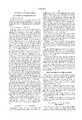
- FIG. 1is a reduced perspective view of the novel low profile ceramic choke incorporating the present invention
- FIG. 2is an enlarged transverse cross-sectional view of the choke and antenna illustrated in FIG. 1 as taken in the direction of arrows 2--2 thereof;
- FIG. 3is a longitudinal cross-sectional view of the choke and antenna shown in FIG. 2 as taken in the direction of arrows 3--3 thereof;
- FIGS. 4 and 5are enlarged fragmentary views of alternate insertion and plating techniques used in producing the inventive choke.
- the novel low profile ceramic choke for use in connection with a global positioning system antennais illustrated in the general direction of arrow 10 which includes a housing 11 having a tapered upper surface 12 and a central opening 13 which exposes a conventional antenna 14. A portion of the top surface 12 has been broken away to expose the ceramic choke, broadly indicated by numeral 15. A suitable connector 16 couples the antenna to suitable receiving circuits.
- the choke 15comprises a ring composed substantially of a dielectric material such as ceramic and the ceramic dielectric is indicated by numeral 17.
- the ceramic ring 15may be produced in a mold as a one-piece or unitary configuration having a plurality of segments such as inner segment 20, segment 21, segment 22, segment 23, and outer segment 24. The respective segments are separated by a circular slot which may provide an air gap but is preferably occupied by a spacer or a wall such as a metal barrier 25 disposed between adjacent segements 21 and 22.
- a plurality of ceramic rings of different diametersis provided which are coaxially disposed with respect to one another and in coaxial relationship with respect to the antenna 14 and the housing 11.
- the ceramic choke 15is of one-piece construction whereby the various segments 20-24 inclusive are joined together by a top edge marginal region, represented by numeral 26.
- a copper plating ring 27is attached to the underside of the ceramic ring 15.
- FIG. 3illustrates that the various ceramic segments are coaxially disposed with respect to one another and that the various segments are separated by the air gap or barrier, indicated by numeral 25.
- the ceramic ring as well as the antenna 14may be housed within the enclosure or housing 11 and that the upper surface 12 is downwardly tapering from the opening 13 towards the outside edge of the housing. This construction permits ready draining of any water that collects or gathers on the surface 12.
- the entire choke 10is composed of a dielectric taking the form of a ceramic composition or any high dielectric constant materials.
- the high dielectric materialselectrically and mechanically reduce the overall size of the choke as compared to conventional chokes.
- the underside of the chokemay be metallized to simulate the metallic cylindrical shell which is commonly used.
- the chokecan be produced in large quantities using molding, plating and other mass-production techniques. Since no machining is required, as in the case of prior art chokes employing solid metal construction, and since ceramic materials are inexpensive, the choke ground planes can be mass-produced at a low cost.
- a preformed metal insert 30, shown in FIG. 4may be made in one-piece and subsequently introduced to the ceramic ring 17 by aligning the metal walls 31 with slots 32 formed in the ceramic ring 17 followed by insertion of the metal walls into the slots.
- the metal formation or layersmay be plated over the exposed surface of the slots and such plating layer is indicated by numeral 33.
- the ring 27may be plated onto the choke after either insertion of the walls or plating of the layers.
Landscapes
- Physics & Mathematics (AREA)
- Electromagnetism (AREA)
- Optics & Photonics (AREA)
- Waveguide Aerials (AREA)
Abstract
Description
1. Field of the Invention
The present invention relates to the field of antenna receiving systems, and more particularly to a novel low profile ceramic choke for global positioning system antennas which is small in size, economical and may be readily mass produced.
2. Brief Description of the Prior Art
In the past, it has been the conventional practice to provide a filter reactor such as a coil or choke serving as an inductance in antenna systems. For example, a global positioning antenna is employed to receive signals which determine the location in longitude and latitude of the receiving system. In such highly precision navigational and surveying applications, the receiving antenna includes a choke slot ground plane incorporated with the receiving antenna in order to reduce phase error. The choke slot ground plane provides a highly capacitive surface that cannot support surface currents. This reduces re-radiation of these currents which in turn adds to the reduction of multi-path errors. Also, the choke slot ground plane allows the antenna to receive a cleaner signal and thus increase location accuracy.
Problems and difficulties have been encountered with conventional antenna chokes since the chokes are composed of metal and are bulky, large in size and, therefore, expensive to fabricate. Fabrication also includes or requires machining. A circular block of metal is machined so as to provide a plurality of concentric walls or ring-like partitions that are integral with a bottom support plate. The opposite side of the construction is open so that a plurality of alternate open spaces are defined between a plurality of different sized concentric thin cylindrical walls. In this manner, the air provides the dielectric between opposing surfaces of the concentric walls and an antenna is supported in the central area having the concentric walls of the choke surrounding the antenna. In order to provide for moisture or humidity protection, a plurality of holes is placed in the support plate so that drainage may be accommodated. Each circular gap or space between adjacent circular walls includes at least one, and preferably, multiple openings in the support plate to provide drainage. Furthermore, the conventional choke may further include a housing which is open in the center in order to expose the antenna while covering the circular choke.
Not only does the aforementioned conventional choke represent a bulky and expensive device to manufacture, but the collection and disposal of moisture within the air gaps of the choke adversely affects the efficiency and performance of the antenna. Also, the collection of moisture on the concentric and spaced-apart walls adversely affects heat dissipation and sometimes requires the expensive and costly necessity of hermetically sealing the metal housing. The ground plate may include holes for drainage in conventional chokes; however, these may clog and prevent drainage.
Therefore, a long-standing need has existed to provide a low profile ceramic choke for global positioning antenna application which is smaller in size than conventional chokes and which is lower cost and may readily be mass-produced without requiring machining and expensive materials.
Accordingly, the above problems and difficulties are avoided by the present invention which provides a novel low profile ceramic choke for global positioning system antenna applications comprising a circular ring of ceramic material having a central opening for placement of an antenna intended to receive frequencies in the megahertz range. The ceramic ring is provided with a plurality of concentric slots of different diameters which are occupied by a metal such as copper or the like. The metal in the slots is integrally joined together on a plated backing which is composed of copper and the backing takes the form of a metallic choke ring at the bottom of the ceramic ring. The top of the ceramic ring is continuous and the plurality of different sized slots terminates short of the top of the ceramic ring so that each of the respective sections of ceramic between adjacent slots is joined along the top of the ceramic ring.
In one form of the invention, a housing may be provided for supporting the antenna and the ceramic choke in coaxial relationship and the housing and choke may include a tapered or sloping top side which promotes moisture runoff collected by rain, humidity or the like.
Therefore, it is among the primary objects of the present invention to provide a novel choke for global positioning system antennas which may be manufactured in a mass-produced manner at an economical and low cost relationship.
Another object of the present invention is to provide a low profile ceramic choke which is small in size as compared to conventional antenna chokes and which may be manufactured at a low cost employing mass-production techniques and fabrication methods.
Still a further object of the present invention is to provide a low profile ceramic choke which incorporates means for eliminating moisture collection due to rain or humidity conditions such that the detrimental effects of humidity and moisture are avoided and good heat dissipation is provided.
An object resides in forming a circular choke with a plurality of concentric spaced-apart slots that may insertably receive a metal insert into each slot or each slot may receive a metal plated coating or layer whereby the choke may be mass produced at a low cost.
The features of the present invention which are believed to be novel are set forth with particularity in the appended claims. The present invention, both as to its organization and manner of operation, together with further objects and advantages thereof, may best be understood with reference to the following description, taken in connection with the accompanying drawings in which:
FIG. 1 is a reduced perspective view of the novel low profile ceramic choke incorporating the present invention;
FIG. 2 is an enlarged transverse cross-sectional view of the choke and antenna illustrated in FIG. 1 as taken in the direction ofarrows 2--2 thereof;
FIG. 3 is a longitudinal cross-sectional view of the choke and antenna shown in FIG. 2 as taken in the direction ofarrows 3--3 thereof;
FIGS. 4 and 5 are enlarged fragmentary views of alternate insertion and plating techniques used in producing the inventive choke.
Referring to FIG. 1, the novel low profile ceramic choke for use in connection with a global positioning system antenna is illustrated in the general direction ofarrow 10 which includes ahousing 11 having a taperedupper surface 12 and acentral opening 13 which exposes aconventional antenna 14. A portion of thetop surface 12 has been broken away to expose the ceramic choke, broadly indicated bynumeral 15. Asuitable connector 16 couples the antenna to suitable receiving circuits.
Referring now in detail to FIG. 2, it can be seen that thechoke 15 comprises a ring composed substantially of a dielectric material such as ceramic and the ceramic dielectric is indicated bynumeral 17. During manufacturing, theceramic ring 15 may be produced in a mold as a one-piece or unitary configuration having a plurality of segments such asinner segment 20,segment 21,segment 22,segment 23, andouter segment 24. The respective segments are separated by a circular slot which may provide an air gap but is preferably occupied by a spacer or a wall such as ametal barrier 25 disposed betweenadjacent segements antenna 14 and thehousing 11. Preferably, theceramic choke 15 is of one-piece construction whereby the various segments 20-24 inclusive are joined together by a top edge marginal region, represented bynumeral 26. Acopper plating ring 27 is attached to the underside of theceramic ring 15.
FIG. 3 illustrates that the various ceramic segments are coaxially disposed with respect to one another and that the various segments are separated by the air gap or barrier, indicated bynumeral 25.
In FIGS. 2 and 3, it can be seen that the ceramic ring as well as theantenna 14 may be housed within the enclosure orhousing 11 and that theupper surface 12 is downwardly tapering from the opening 13 towards the outside edge of the housing. This construction permits ready draining of any water that collects or gathers on thesurface 12.
In view of the foregoing, it can be seen that theentire choke 10 is composed of a dielectric taking the form of a ceramic composition or any high dielectric constant materials. The high dielectric materials electrically and mechanically reduce the overall size of the choke as compared to conventional chokes. The underside of the choke may be metallized to simulate the metallic cylindrical shell which is commonly used. The choke can be produced in large quantities using molding, plating and other mass-production techniques. Since no machining is required, as in the case of prior art chokes employing solid metal construction, and since ceramic materials are inexpensive, the choke ground planes can be mass-produced at a low cost.
As an example, apreformed metal insert 30, shown in FIG. 4, may be made in one-piece and subsequently introduced to theceramic ring 17 by aligning themetal walls 31 withslots 32 formed in theceramic ring 17 followed by insertion of the metal walls into the slots. Alternately, as shown in FIG. 5, the metal formation or layers may be plated over the exposed surface of the slots and such plating layer is indicated bynumeral 33. Also, thering 27 may be plated onto the choke after either insertion of the walls or plating of the layers.
While particular embodiments of the present invention have been shown and described, it will be obvious to those skilled in the art that changes and modifications may be made without departing from this invention in its broader aspects and, therefore, the aim in the appended claims is to cover all such changes and modifications as fall within the true spirit and scope of this invention.
Claims (10)
1. A low profile choke for a global positioning antenna system comprising:
a ring of high dielectric constant material having an open center and a circular peripheral edge;
a plurality of concentric segments forming said ring of high dielectric constant material providing a highly capacitive surface;
a metallized undersurface backing carried on said ring;
an antenna disposed in said open center of said ring; and
an upper surface of said ring being tapered to provide moisture runoff.
2. The low profile choke defined in claim 1 wherein:
said concentric segments of different diameters and are arranged in coaxial relationship.
3. The low profile choke defined in claim 2 wherein:
said concentric segments are integrally formed and connected together by a top edge marginal region to provide a unitary construction.
4. The low profile choke defined in claim 3 including:
a metal housing surrounding said ring of high dielectric constant material and said housing having a top tapered surface.
5. The low profile choke defined in claim 4 wherein:
said high dielectric constant material is of ceramic composition having fabrication characteristics adapted to be formed in a mold.
6. A low profile choke for global positioning antenna systems comprising:
a ring of ceramic material constituting a high idelectric constant material;
an antenna located in the center of said ring so as to be flush with said ring;
said ring being integrally formed with a plurality of concentric segments in fixed spaced-apart relationship;
a bottom carried on said ring of metallized composition; and
a top of said ring being of frustro-conical configuration to avoid collection of moisture.
7. The low profile choke defined in claim 6 wherein:
said ceramic material ring is of high dielectric density providing reduced thickness, low profile and decreased overall diameter.
8. A low profile choke for a global positioning antenna system comprising:
a ring of high dielectric constant material having an open center and a circular peripheral edge;
a plurality of concentric segments forming said ring of high dielectric constant material providing a highly capacitive surface;
a metallized undersurface backing carried on said ring;
said plurality of concentric segments are arranged in fixed spaced-apart relationship so as to define a slot or gap therebetween; and
a metal formation occupying said slot or gap.
9. The low profile choke defined in claim 8 wherein:
said metal formation is a plated layer of metal composition.
10. The low profile choke defined in claim 8 wherein:
said metal formation is an insert of metal composition;
said insert includes a plurality of spaced-apart walls insertable into said slots or gaps.
Priority Applications (1)
| Application Number | Priority Date | Filing Date | Title |
|---|---|---|---|
| US09/075,009US6040805A (en) | 1998-05-08 | 1998-05-08 | Low profile ceramic choke |
Applications Claiming Priority (1)
| Application Number | Priority Date | Filing Date | Title |
|---|---|---|---|
| US09/075,009US6040805A (en) | 1998-05-08 | 1998-05-08 | Low profile ceramic choke |
Publications (1)
| Publication Number | Publication Date |
|---|---|
| US6040805Atrue US6040805A (en) | 2000-03-21 |
Family
ID=22122969
Family Applications (1)
| Application Number | Title | Priority Date | Filing Date |
|---|---|---|---|
| US09/075,009Expired - Fee RelatedUS6040805A (en) | 1998-05-08 | 1998-05-08 | Low profile ceramic choke |
Country Status (1)
| Country | Link |
|---|---|
| US (1) | US6040805A (en) |
Cited By (58)
| Publication number | Priority date | Publication date | Assignee | Title |
|---|---|---|---|---|
| USD444144S1 (en) | 2000-07-12 | 2001-06-26 | Trimble Navigation Limited | Antenna housing |
| US6278407B1 (en)* | 1998-02-24 | 2001-08-21 | Topcon Positioning Systems, Inc. | Dual-frequency choke-ring ground planes |
| US6597323B2 (en)* | 2000-03-03 | 2003-07-22 | Anritsu Corporation | Dielectric leaky wave antenna having mono-layer structure |
| US20030184479A1 (en)* | 2002-03-27 | 2003-10-02 | Her Majesty The Queen In Right Of Canada | Non-planar ringed antenna system |
| US20040227685A1 (en)* | 2003-05-12 | 2004-11-18 | Mccandless Jay | Method and apparatus for forming symmetrical energy patterns in beam forming antennas |
| US20050225474A1 (en)* | 2004-03-17 | 2005-10-13 | Deutsches Zentrum Fur Luft-Und Raumfahrt E.V. | Aircraft antenna assembly for wireless signal reception |
| US20060092079A1 (en)* | 2004-10-01 | 2006-05-04 | De Rochemont L P | Ceramic antenna module and methods of manufacture thereof |
| US20060238427A1 (en)* | 2005-04-22 | 2006-10-26 | Ferguson Stanley D | Phased array antenna choke plate method and apparatus |
| US20070139976A1 (en)* | 2005-06-30 | 2007-06-21 | Derochemont L P | Power management module and method of manufacture |
| US7375688B1 (en) | 2006-12-08 | 2008-05-20 | The Boeing Company | Electromagnetic compatability with window-choke rings |
| US20090096704A1 (en)* | 2007-09-17 | 2009-04-16 | Physical Sciences, Inc. | Non-Cutoff Frequency Selective Surface Ground Plane Antenna Assembly |
| RU2446522C2 (en)* | 2010-04-14 | 2012-03-27 | Дмитрий Витальевич Татарников | Screen for inhibiting multibeam signal reception and antenna system having said screen |
| US20120139808A1 (en)* | 2010-12-01 | 2012-06-07 | Samsung Electronics Co. Ltd. | Antenna for global positioning system |
| US20120154241A1 (en)* | 2010-01-22 | 2012-06-21 | Topcon Positioning Systems, Inc. | Flat Semi-Transparent Ground Plane for Reducing Multipath |
| US8354294B2 (en) | 2006-01-24 | 2013-01-15 | De Rochemont L Pierre | Liquid chemical deposition apparatus and process and products therefrom |
| CN103280625A (en)* | 2013-04-26 | 2013-09-04 | 湖南航天环宇通信科技有限责任公司 | GNSS (Global Navigation Satellite System) high-precision measuring antenna |
| US8552708B2 (en) | 2010-06-02 | 2013-10-08 | L. Pierre de Rochemont | Monolithic DC/DC power management module with surface FET |
| US8715839B2 (en) | 2005-06-30 | 2014-05-06 | L. Pierre de Rochemont | Electrical components and method of manufacture |
| RU2517390C2 (en)* | 2012-05-31 | 2014-05-27 | Открытое акционерное общество "Научно-исследовательский институт космического приборостроения" (ОАО "НИИ КП") | Superlight antimultipath device |
| US8749054B2 (en) | 2010-06-24 | 2014-06-10 | L. Pierre de Rochemont | Semiconductor carrier with vertical power FET module |
| US8779489B2 (en) | 2010-08-23 | 2014-07-15 | L. Pierre de Rochemont | Power FET with a resonant transistor gate |
| JP2014154960A (en)* | 2013-02-06 | 2014-08-25 | Mitsubishi Electric Corp | Primary radiator for antenna device, and antenna device |
| US8922347B1 (en) | 2009-06-17 | 2014-12-30 | L. Pierre de Rochemont | R.F. energy collection circuit for wireless devices |
| US8952858B2 (en) | 2009-06-17 | 2015-02-10 | L. Pierre de Rochemont | Frequency-selective dipole antennas |
| US9023493B2 (en) | 2010-07-13 | 2015-05-05 | L. Pierre de Rochemont | Chemically complex ablative max-phase material and method of manufacture |
| US9123768B2 (en) | 2010-11-03 | 2015-09-01 | L. Pierre de Rochemont | Semiconductor chip carriers with monolithically integrated quantum dot devices and method of manufacture thereof |
| RU2570844C1 (en)* | 2014-07-01 | 2015-12-10 | Открытое акционерное общество "Объединенная ракетно-космическая корпорация" (ОАО "ОРКК") | Geodetic antenna |
| US9407006B1 (en)* | 2013-03-15 | 2016-08-02 | Neptune Technology Group Inc. | Choke for antenna |
| US9481777B2 (en) | 2012-03-30 | 2016-11-01 | The Procter & Gamble Company | Method of dewatering in a continuous high internal phase emulsion foam forming process |
| RU2602772C2 (en)* | 2013-04-11 | 2016-11-20 | Общество с ограниченной ответственностью "Топкон Позишионинг Системс" | Screens to reduce effect of multipath reception |
| US10455350B2 (en) | 2016-07-10 | 2019-10-22 | ZaiNar, Inc. | Method and system for radiolocation asset tracking via a mesh network |
| CN113131175A (en)* | 2019-12-31 | 2021-07-16 | 中国科学院国家空间科学中心 | Multi-band circularly polarized GNSS positioning antenna |
| USD940149S1 (en) | 2017-06-08 | 2022-01-04 | Insulet Corporation | Display screen with a graphical user interface |
| US11271709B1 (en) | 2018-09-28 | 2022-03-08 | ZaiNar, Inc. | Frequency and gain calibration for time synchronization in a network |
| US11271713B2 (en) | 2018-05-07 | 2022-03-08 | ZaiNar, Inc. | Methods for nanosecond-scale time synchronization over a network |
| US11552398B2 (en) | 2014-11-18 | 2023-01-10 | Commscope Technologies Llc | Cloaked low band elements for multiband radiating arrays |
| USD977502S1 (en) | 2020-06-09 | 2023-02-07 | Insulet Corporation | Display screen with graphical user interface |
| US11658798B1 (en) | 2018-05-07 | 2023-05-23 | ZaiNar, Inc. | Methods for time synchronization and localization in a mesh network |
| US11686805B1 (en) | 2016-07-10 | 2023-06-27 | ZaiNar, Inc. | Method and system for radiofrequency localization of transmitting devices via a mesh network |
| US20230253702A1 (en)* | 2022-02-10 | 2023-08-10 | Swiftlink Technologies Co., Ltd. | Periodic Mode-Selective Structure for Surface Wave Scattering Mitigation in Millimeter Wave Antenna Arrays |
| US11857763B2 (en) | 2016-01-14 | 2024-01-02 | Insulet Corporation | Adjusting insulin delivery rates |
| US11865299B2 (en) | 2008-08-20 | 2024-01-09 | Insulet Corporation | Infusion pump systems and methods |
| US11929158B2 (en) | 2016-01-13 | 2024-03-12 | Insulet Corporation | User interface for diabetes management system |
| USD1020794S1 (en) | 2018-04-02 | 2024-04-02 | Bigfoot Biomedical, Inc. | Medication delivery device with icons |
| USD1024090S1 (en) | 2019-01-09 | 2024-04-23 | Bigfoot Biomedical, Inc. | Display screen or portion thereof with graphical user interface associated with insulin delivery |
| US11968601B2 (en) | 2022-04-20 | 2024-04-23 | ZaiNar, Inc. | System and methods for asset tracking, asset grouping, and error recovery |
| US11969579B2 (en) | 2017-01-13 | 2024-04-30 | Insulet Corporation | Insulin delivery methods, systems and devices |
| WO2024134016A1 (en) | 2022-12-19 | 2024-06-27 | Koherent Oy | A tx/rx antenna structure enabling accurate terrestrial positioning |
| US12042630B2 (en) | 2017-01-13 | 2024-07-23 | Insulet Corporation | System and method for adjusting insulin delivery |
| US12064591B2 (en) | 2013-07-19 | 2024-08-20 | Insulet Corporation | Infusion pump system and method |
| US12076160B2 (en) | 2016-12-12 | 2024-09-03 | Insulet Corporation | Alarms and alerts for medication delivery devices and systems |
| US12097355B2 (en) | 2023-01-06 | 2024-09-24 | Insulet Corporation | Automatically or manually initiated meal bolus delivery with subsequent automatic safety constraint relaxation |
| US12106837B2 (en) | 2016-01-14 | 2024-10-01 | Insulet Corporation | Occlusion resolution in medication delivery devices, systems, and methods |
| US12318594B2 (en) | 2016-05-26 | 2025-06-03 | Insulet Corporation | On-body interlock for drug delivery device |
| US12318577B2 (en) | 2017-01-13 | 2025-06-03 | Insulet Corporation | System and method for adjusting insulin delivery |
| US12343502B2 (en) | 2017-01-13 | 2025-07-01 | Insulet Corporation | System and method for adjusting insulin delivery |
| US12383166B2 (en) | 2016-05-23 | 2025-08-12 | Insulet Corporation | Insulin delivery system and methods with risk-based set points |
| DE102024109227B3 (en)* | 2024-04-02 | 2025-09-18 | Deutsches Zentrum für Luft- und Raumfahrt e.V. | Antenna with height-adjustable adjustment elements |
Citations (4)
| Publication number | Priority date | Publication date | Assignee | Title |
|---|---|---|---|---|
| US2413085A (en)* | 1945-01-29 | 1946-12-24 | Philco Corp | Antenna system |
| US3434774A (en)* | 1965-02-02 | 1969-03-25 | Bell Telephone Labor Inc | Waveguide for millimeter and optical waves |
| US4546459A (en)* | 1982-12-02 | 1985-10-08 | Magnavox Government And Industrial Electronics Company | Method and apparatus for a phased array transducer |
| US5434585A (en)* | 1992-11-20 | 1995-07-18 | Gardiner Communications, Inc. | Microwave antenna having a ground isolated feedhorn |
- 1998
- 1998-05-08USUS09/075,009patent/US6040805A/ennot_activeExpired - Fee Related
Patent Citations (4)
| Publication number | Priority date | Publication date | Assignee | Title |
|---|---|---|---|---|
| US2413085A (en)* | 1945-01-29 | 1946-12-24 | Philco Corp | Antenna system |
| US3434774A (en)* | 1965-02-02 | 1969-03-25 | Bell Telephone Labor Inc | Waveguide for millimeter and optical waves |
| US4546459A (en)* | 1982-12-02 | 1985-10-08 | Magnavox Government And Industrial Electronics Company | Method and apparatus for a phased array transducer |
| US5434585A (en)* | 1992-11-20 | 1995-07-18 | Gardiner Communications, Inc. | Microwave antenna having a ground isolated feedhorn |
Cited By (98)
| Publication number | Priority date | Publication date | Assignee | Title |
|---|---|---|---|---|
| US6278407B1 (en)* | 1998-02-24 | 2001-08-21 | Topcon Positioning Systems, Inc. | Dual-frequency choke-ring ground planes |
| US6597323B2 (en)* | 2000-03-03 | 2003-07-22 | Anritsu Corporation | Dielectric leaky wave antenna having mono-layer structure |
| USD467242S1 (en) | 2000-07-12 | 2002-12-17 | Trimble Navigation Limited | Antenna housing |
| USD444144S1 (en) | 2000-07-12 | 2001-06-26 | Trimble Navigation Limited | Antenna housing |
| US9735148B2 (en) | 2002-02-19 | 2017-08-15 | L. Pierre de Rochemont | Semiconductor carrier with vertical power FET module |
| US20030184479A1 (en)* | 2002-03-27 | 2003-10-02 | Her Majesty The Queen In Right Of Canada | Non-planar ringed antenna system |
| US6876327B2 (en) | 2002-03-27 | 2005-04-05 | Her Majesty The Queen In Right Of Canada, As Represented By The Minister Of National Defense | Non-planar ringed antenna system |
| US20040227685A1 (en)* | 2003-05-12 | 2004-11-18 | Mccandless Jay | Method and apparatus for forming symmetrical energy patterns in beam forming antennas |
| US7009571B2 (en)* | 2003-05-12 | 2006-03-07 | Bwa Technology, Inc. | Method and apparatus for forming symmetrical energy patterns in beam forming antennas |
| US20050225474A1 (en)* | 2004-03-17 | 2005-10-13 | Deutsches Zentrum Fur Luft-Und Raumfahrt E.V. | Aircraft antenna assembly for wireless signal reception |
| DE102004013358A1 (en)* | 2004-03-17 | 2005-10-20 | Deutsch Zentr Luft & Raumfahrt | Aircraft antenna arrangement for receiving radio signals |
| US20090011922A1 (en)* | 2004-10-01 | 2009-01-08 | De Rochemont L Pierre | Ceramic antenna module and methods of manufacture thereof |
| US9882274B2 (en) | 2004-10-01 | 2018-01-30 | L. Pierre de Rochemont | Ceramic antenna module and methods of manufacture thereof |
| US10673130B2 (en) | 2004-10-01 | 2020-06-02 | L. Pierre de Rochemont | Ceramic antenna module and methods of manufacture thereof |
| US20060092079A1 (en)* | 2004-10-01 | 2006-05-04 | De Rochemont L P | Ceramic antenna module and methods of manufacture thereof |
| US7405698B2 (en) | 2004-10-01 | 2008-07-29 | De Rochemont L Pierre | Ceramic antenna module and methods of manufacture thereof |
| US8593819B2 (en) | 2004-10-01 | 2013-11-26 | L. Pierre de Rochemont | Ceramic antenna module and methods of manufacture thereof |
| US9520649B2 (en) | 2004-10-01 | 2016-12-13 | L. Pierre de Rochemont | Ceramic antenna module and methods of manufacture thereof |
| US8178457B2 (en) | 2004-10-01 | 2012-05-15 | De Rochemont L Pierre | Ceramic antenna module and methods of manufacture thereof |
| US7295165B2 (en)* | 2005-04-22 | 2007-11-13 | The Boeing Company | Phased array antenna choke plate method and apparatus |
| US20060238427A1 (en)* | 2005-04-22 | 2006-10-26 | Ferguson Stanley D | Phased array antenna choke plate method and apparatus |
| US9905928B2 (en) | 2005-06-30 | 2018-02-27 | L. Pierre de Rochemont | Electrical components and method of manufacture |
| US8715839B2 (en) | 2005-06-30 | 2014-05-06 | L. Pierre de Rochemont | Electrical components and method of manufacture |
| US10475568B2 (en) | 2005-06-30 | 2019-11-12 | L. Pierre De Rochemont | Power management module and method of manufacture |
| US8350657B2 (en) | 2005-06-30 | 2013-01-08 | Derochemont L Pierre | Power management module and method of manufacture |
| US20070139976A1 (en)* | 2005-06-30 | 2007-06-21 | Derochemont L P | Power management module and method of manufacture |
| US8354294B2 (en) | 2006-01-24 | 2013-01-15 | De Rochemont L Pierre | Liquid chemical deposition apparatus and process and products therefrom |
| US8715814B2 (en) | 2006-01-24 | 2014-05-06 | L. Pierre de Rochemont | Liquid chemical deposition apparatus and process and products therefrom |
| GB2444647B (en)* | 2006-12-08 | 2009-05-06 | Boeing Co | Mobile platform window choke rings for controlling electromagnetic interference with electronics systems |
| US7525496B2 (en)* | 2006-12-08 | 2009-04-28 | The Boeing Company | Mobile platform window choke rings for controlling electromagnetic interference with electronics systems |
| US7375688B1 (en) | 2006-12-08 | 2008-05-20 | The Boeing Company | Electromagnetic compatability with window-choke rings |
| GB2444647A (en)* | 2006-12-08 | 2008-06-11 | Boeing Co | Mobile platform window choke rings for controlling electromagnetic interference with electronics systems |
| US20080218421A1 (en)* | 2006-12-08 | 2008-09-11 | The Boeing Company | Mobile platform window choke rings for controlling electromagnetic interference with electronics systems |
| US20090096704A1 (en)* | 2007-09-17 | 2009-04-16 | Physical Sciences, Inc. | Non-Cutoff Frequency Selective Surface Ground Plane Antenna Assembly |
| US8451190B2 (en) | 2007-09-17 | 2013-05-28 | Physical Sciences, Inc. | Non-cutoff frequency selective surface ground plane antenna assembly |
| US8004474B2 (en) | 2007-09-17 | 2011-08-23 | Physical Sciences, Inc. | Non-cutoff frequency selective surface ground plane antenna assembly |
| US12296139B2 (en) | 2008-08-20 | 2025-05-13 | Insulet Corporation | Infusion pump systems and methods |
| US11865299B2 (en) | 2008-08-20 | 2024-01-09 | Insulet Corporation | Infusion pump systems and methods |
| US8922347B1 (en) | 2009-06-17 | 2014-12-30 | L. Pierre de Rochemont | R.F. energy collection circuit for wireless devices |
| US9847581B2 (en) | 2009-06-17 | 2017-12-19 | L. Pierre de Rochemont | Frequency-selective dipole antennas |
| US8952858B2 (en) | 2009-06-17 | 2015-02-10 | L. Pierre de Rochemont | Frequency-selective dipole antennas |
| US11063365B2 (en) | 2009-06-17 | 2021-07-13 | L. Pierre de Rochemont | Frequency-selective dipole antennas |
| US9893564B2 (en) | 2009-06-17 | 2018-02-13 | L. Pierre de Rochemont | R.F. energy collection circuit for wireless devices |
| US9048546B2 (en)* | 2010-01-22 | 2015-06-02 | Topcon Positioning Systems, Inc. | Flat semi-transparent ground plane for reducing multipath reception and antenna system |
| US20120154241A1 (en)* | 2010-01-22 | 2012-06-21 | Topcon Positioning Systems, Inc. | Flat Semi-Transparent Ground Plane for Reducing Multipath |
| RU2446522C2 (en)* | 2010-04-14 | 2012-03-27 | Дмитрий Витальевич Татарников | Screen for inhibiting multibeam signal reception and antenna system having said screen |
| US8552708B2 (en) | 2010-06-02 | 2013-10-08 | L. Pierre de Rochemont | Monolithic DC/DC power management module with surface FET |
| US10483260B2 (en) | 2010-06-24 | 2019-11-19 | L. Pierre de Rochemont | Semiconductor carrier with vertical power FET module |
| US8749054B2 (en) | 2010-06-24 | 2014-06-10 | L. Pierre de Rochemont | Semiconductor carrier with vertical power FET module |
| US10683705B2 (en) | 2010-07-13 | 2020-06-16 | L. Pierre de Rochemont | Cutting tool and method of manufacture |
| US9023493B2 (en) | 2010-07-13 | 2015-05-05 | L. Pierre de Rochemont | Chemically complex ablative max-phase material and method of manufacture |
| US8779489B2 (en) | 2010-08-23 | 2014-07-15 | L. Pierre de Rochemont | Power FET with a resonant transistor gate |
| US9123768B2 (en) | 2010-11-03 | 2015-09-01 | L. Pierre de Rochemont | Semiconductor chip carriers with monolithically integrated quantum dot devices and method of manufacture thereof |
| US10777409B2 (en) | 2010-11-03 | 2020-09-15 | L. Pierre de Rochemont | Semiconductor chip carriers with monolithically integrated quantum dot devices and method of manufacture thereof |
| US20120139808A1 (en)* | 2010-12-01 | 2012-06-07 | Samsung Electronics Co. Ltd. | Antenna for global positioning system |
| US9481777B2 (en) | 2012-03-30 | 2016-11-01 | The Procter & Gamble Company | Method of dewatering in a continuous high internal phase emulsion foam forming process |
| US9809693B2 (en) | 2012-03-30 | 2017-11-07 | The Procter & Gamble Company | Method of dewatering in a continuous high internal phase emulsion foam forming process |
| RU2517390C2 (en)* | 2012-05-31 | 2014-05-27 | Открытое акционерное общество "Научно-исследовательский институт космического приборостроения" (ОАО "НИИ КП") | Superlight antimultipath device |
| JP2014154960A (en)* | 2013-02-06 | 2014-08-25 | Mitsubishi Electric Corp | Primary radiator for antenna device, and antenna device |
| US9407006B1 (en)* | 2013-03-15 | 2016-08-02 | Neptune Technology Group Inc. | Choke for antenna |
| RU2602772C2 (en)* | 2013-04-11 | 2016-11-20 | Общество с ограниченной ответственностью "Топкон Позишионинг Системс" | Screens to reduce effect of multipath reception |
| CN103280625B (en)* | 2013-04-26 | 2016-04-06 | 湖南航天环宇通信科技股份有限公司 | GNSS high-acruracy survey antenna |
| CN103280625A (en)* | 2013-04-26 | 2013-09-04 | 湖南航天环宇通信科技有限责任公司 | GNSS (Global Navigation Satellite System) high-precision measuring antenna |
| US12064591B2 (en) | 2013-07-19 | 2024-08-20 | Insulet Corporation | Infusion pump system and method |
| RU2570844C1 (en)* | 2014-07-01 | 2015-12-10 | Открытое акционерное общество "Объединенная ракетно-космическая корпорация" (ОАО "ОРКК") | Geodetic antenna |
| US11870160B2 (en) | 2014-11-18 | 2024-01-09 | Commscope Technologies Llc | Cloaked low band elements for multiband radiating arrays |
| US12394901B2 (en) | 2014-11-18 | 2025-08-19 | Outdoor Wireless Networks LLC | Cloaked low band elements for multiband radiating arrays |
| US11552398B2 (en) | 2014-11-18 | 2023-01-10 | Commscope Technologies Llc | Cloaked low band elements for multiband radiating arrays |
| US11929158B2 (en) | 2016-01-13 | 2024-03-12 | Insulet Corporation | User interface for diabetes management system |
| US12106837B2 (en) | 2016-01-14 | 2024-10-01 | Insulet Corporation | Occlusion resolution in medication delivery devices, systems, and methods |
| US11857763B2 (en) | 2016-01-14 | 2024-01-02 | Insulet Corporation | Adjusting insulin delivery rates |
| US12303668B2 (en) | 2016-01-14 | 2025-05-20 | Insulet Corporation | Adjusting insulin delivery rates |
| US12303667B2 (en) | 2016-01-14 | 2025-05-20 | Insulet Corporation | Adjusting insulin delivery rates |
| US12383166B2 (en) | 2016-05-23 | 2025-08-12 | Insulet Corporation | Insulin delivery system and methods with risk-based set points |
| US12318594B2 (en) | 2016-05-26 | 2025-06-03 | Insulet Corporation | On-body interlock for drug delivery device |
| US10455350B2 (en) | 2016-07-10 | 2019-10-22 | ZaiNar, Inc. | Method and system for radiolocation asset tracking via a mesh network |
| US11686805B1 (en) | 2016-07-10 | 2023-06-27 | ZaiNar, Inc. | Method and system for radiofrequency localization of transmitting devices via a mesh network |
| US12076160B2 (en) | 2016-12-12 | 2024-09-03 | Insulet Corporation | Alarms and alerts for medication delivery devices and systems |
| US12161841B2 (en) | 2017-01-13 | 2024-12-10 | Insulet Corporation | Insulin delivery methods, systems and devices |
| US12343502B2 (en) | 2017-01-13 | 2025-07-01 | Insulet Corporation | System and method for adjusting insulin delivery |
| US11969579B2 (en) | 2017-01-13 | 2024-04-30 | Insulet Corporation | Insulin delivery methods, systems and devices |
| US12318577B2 (en) | 2017-01-13 | 2025-06-03 | Insulet Corporation | System and method for adjusting insulin delivery |
| US12042630B2 (en) | 2017-01-13 | 2024-07-23 | Insulet Corporation | System and method for adjusting insulin delivery |
| USD940149S1 (en) | 2017-06-08 | 2022-01-04 | Insulet Corporation | Display screen with a graphical user interface |
| USD1020794S1 (en) | 2018-04-02 | 2024-04-02 | Bigfoot Biomedical, Inc. | Medication delivery device with icons |
| US11271713B2 (en) | 2018-05-07 | 2022-03-08 | ZaiNar, Inc. | Methods for nanosecond-scale time synchronization over a network |
| US11658798B1 (en) | 2018-05-07 | 2023-05-23 | ZaiNar, Inc. | Methods for time synchronization and localization in a mesh network |
| US11271709B1 (en) | 2018-09-28 | 2022-03-08 | ZaiNar, Inc. | Frequency and gain calibration for time synchronization in a network |
| USD1024090S1 (en) | 2019-01-09 | 2024-04-23 | Bigfoot Biomedical, Inc. | Display screen or portion thereof with graphical user interface associated with insulin delivery |
| CN113131175A (en)* | 2019-12-31 | 2021-07-16 | 中国科学院国家空间科学中心 | Multi-band circularly polarized GNSS positioning antenna |
| CN113131175B (en)* | 2019-12-31 | 2022-10-04 | 中国科学院国家空间科学中心 | A multi-band circularly polarized GNSS positioning antenna |
| USD977502S1 (en) | 2020-06-09 | 2023-02-07 | Insulet Corporation | Display screen with graphical user interface |
| US12308517B2 (en)* | 2022-02-10 | 2025-05-20 | Swiftlink Technologies Inc. | Periodic mode-selective structure for surface wave scattering mitigation in millimeter wave antenna arrays |
| US20230253702A1 (en)* | 2022-02-10 | 2023-08-10 | Swiftlink Technologies Co., Ltd. | Periodic Mode-Selective Structure for Surface Wave Scattering Mitigation in Millimeter Wave Antenna Arrays |
| US11968601B2 (en) | 2022-04-20 | 2024-04-23 | ZaiNar, Inc. | System and methods for asset tracking, asset grouping, and error recovery |
| WO2024134016A1 (en) | 2022-12-19 | 2024-06-27 | Koherent Oy | A tx/rx antenna structure enabling accurate terrestrial positioning |
| US12097355B2 (en) | 2023-01-06 | 2024-09-24 | Insulet Corporation | Automatically or manually initiated meal bolus delivery with subsequent automatic safety constraint relaxation |
| DE102024109227B3 (en)* | 2024-04-02 | 2025-09-18 | Deutsches Zentrum für Luft- und Raumfahrt e.V. | Antenna with height-adjustable adjustment elements |
Similar Documents
| Publication | Publication Date | Title |
|---|---|---|
| US6040805A (en) | Low profile ceramic choke | |
| US8952595B2 (en) | Micro-electro-mechanical transducers | |
| KR102503237B1 (en) | Radio frequency filter | |
| WO2001056113A1 (en) | Antenna assembly for subsurface meter pits | |
| WO1998057311A2 (en) | Telemetry antenna system | |
| CA2072277A1 (en) | Inductance element | |
| JPH06503930A (en) | microwave antenna | |
| US4394633A (en) | Microstrip circuit with suspended substrate stripline regions embedded therein | |
| US20040201533A1 (en) | Crossed-slot antenna for mobile satellite and terrestrial radio reception | |
| US20040183627A1 (en) | Compact waveguide filter | |
| WO2000076019A1 (en) | Temperature-compensated rod resonator | |
| CN117631000A (en) | Positioning integrated device and its driving equipment | |
| JPH0624284B2 (en) | Resonator | |
| KR100610848B1 (en) | Beam tilt microstrip patch antenna | |
| CN214849031U (en) | AFU Antenna Structure | |
| CN111129693B (en) | An Assembly Structure for VICTS Phased Array Panel Array Antenna | |
| JPS61500944A (en) | Horn antenna structure with microwave detection circuit | |
| JPH08125432A (en) | Feedphone integrated LNB | |
| CN100570954C (en) | Antenna device | |
| CN112201919A (en) | Active antenna unit, shell and supporting cover | |
| CN220963706U (en) | Dielectric filter and communication device | |
| CN210723361U (en) | Dual-band omnidirectional antenna based on four-arm spiral structure | |
| CN221598562U (en) | Electromagnetic shielding cover | |
| JPH01268301A (en) | Converter for satellite communication | |
| US12407108B2 (en) | Multi-band patch antenna |
Legal Events
| Date | Code | Title | Description |
|---|---|---|---|
| AS | Assignment | Owner name:ANTCOM CORPORATION, CALIFORNIA Free format text:ASSIGNMENT OF ASSIGNORS INTEREST;ASSIGNORS:CHENG, GEORGE;HUYNH, SON HUY;REEL/FRAME:009477/0687 Effective date:19980508 | |
| REMI | Maintenance fee reminder mailed | ||
| LAPS | Lapse for failure to pay maintenance fees | ||
| FP | Lapsed due to failure to pay maintenance fee | Effective date:20040321 | |
| STCH | Information on status: patent discontinuation | Free format text:PATENT EXPIRED DUE TO NONPAYMENT OF MAINTENANCE FEES UNDER 37 CFR 1.362 |