US6040803A - Dual band diversity antenna having parasitic radiating element - Google Patents
Dual band diversity antenna having parasitic radiating elementDownload PDFInfo
- Publication number
- US6040803A US6040803AUS09/026,456US2645698AUS6040803AUS 6040803 AUS6040803 AUS 6040803AUS 2645698 AUS2645698 AUS 2645698AUS 6040803 AUS6040803 AUS 6040803A
- Authority
- US
- United States
- Prior art keywords
- radiating element
- antenna
- dielectric substrate
- ground
- feed
- Prior art date
- Legal status (The legal status is an assumption and is not a legal conclusion. Google has not performed a legal analysis and makes no representation as to the accuracy of the status listed.)
- Expired - Lifetime
Links
Images

Classifications
- H—ELECTRICITY
- H01—ELECTRIC ELEMENTS
- H01Q—ANTENNAS, i.e. RADIO AERIALS
- H01Q5/00—Arrangements for simultaneous operation of antennas on two or more different wavebands, e.g. dual-band or multi-band arrangements
- H—ELECTRICITY
- H04—ELECTRIC COMMUNICATION TECHNIQUE
- H04B—TRANSMISSION
- H04B1/00—Details of transmission systems, not covered by a single one of groups H04B3/00 - H04B13/00; Details of transmission systems not characterised by the medium used for transmission
- H04B1/38—Transceivers, i.e. devices in which transmitter and receiver form a structural unit and in which at least one part is used for functions of transmitting and receiving
- H04B1/3827—Portable transceivers
- H04B1/3833—Hand-held transceivers
- H—ELECTRICITY
- H01—ELECTRIC ELEMENTS
- H01Q—ANTENNAS, i.e. RADIO AERIALS
- H01Q1/00—Details of, or arrangements associated with, antennas
- H01Q1/12—Supports; Mounting means
- H01Q1/22—Supports; Mounting means by structural association with other equipment or articles
- H01Q1/24—Supports; Mounting means by structural association with other equipment or articles with receiving set
- H01Q1/241—Supports; Mounting means by structural association with other equipment or articles with receiving set used in mobile communications, e.g. GSM
- H01Q1/242—Supports; Mounting means by structural association with other equipment or articles with receiving set used in mobile communications, e.g. GSM specially adapted for hand-held use
- H01Q1/243—Supports; Mounting means by structural association with other equipment or articles with receiving set used in mobile communications, e.g. GSM specially adapted for hand-held use with built-in antennas
- H—ELECTRICITY
- H01—ELECTRIC ELEMENTS
- H01Q—ANTENNAS, i.e. RADIO AERIALS
- H01Q1/00—Details of, or arrangements associated with, antennas
- H01Q1/36—Structural form of radiating elements, e.g. cone, spiral, umbrella; Particular materials used therewith
- H—ELECTRICITY
- H01—ELECTRIC ELEMENTS
- H01Q—ANTENNAS, i.e. RADIO AERIALS
- H01Q1/00—Details of, or arrangements associated with, antennas
- H01Q1/36—Structural form of radiating elements, e.g. cone, spiral, umbrella; Particular materials used therewith
- H01Q1/38—Structural form of radiating elements, e.g. cone, spiral, umbrella; Particular materials used therewith formed by a conductive layer on an insulating support
- H—ELECTRICITY
- H01—ELECTRIC ELEMENTS
- H01Q—ANTENNAS, i.e. RADIO AERIALS
- H01Q5/00—Arrangements for simultaneous operation of antennas on two or more different wavebands, e.g. dual-band or multi-band arrangements
- H01Q5/30—Arrangements for providing operation on different wavebands
- H01Q5/378—Combination of fed elements with parasitic elements
- H—ELECTRICITY
- H01—ELECTRIC ELEMENTS
- H01Q—ANTENNAS, i.e. RADIO AERIALS
- H01Q9/00—Electrically-short antennas having dimensions not more than twice the operating wavelength and consisting of conductive active radiating elements
- H01Q9/04—Resonant antennas
- H01Q9/0407—Substantially flat resonant element parallel to ground plane, e.g. patch antenna
- H01Q9/0414—Substantially flat resonant element parallel to ground plane, e.g. patch antenna in a stacked or folded configuration
- H—ELECTRICITY
- H01—ELECTRIC ELEMENTS
- H01Q—ANTENNAS, i.e. RADIO AERIALS
- H01Q9/00—Electrically-short antennas having dimensions not more than twice the operating wavelength and consisting of conductive active radiating elements
- H01Q9/04—Resonant antennas
- H01Q9/0407—Substantially flat resonant element parallel to ground plane, e.g. patch antenna
- H01Q9/0421—Substantially flat resonant element parallel to ground plane, e.g. patch antenna with a shorting wall or a shorting pin at one end of the element
Definitions
- the present inventionrelates generally to antennas, and more particularly to diversity antennas used within communication devices.
- Antennas for personal communication devicesmay not function adequately when in close proximity to a user during operation, or when a user is moving during operation of a device. Close proximity to objects or movement of a user during operation of a radiotelephone may result in degraded signal quality or fluctuations in signal strength, known as multipath fading. Diversity antennas have been designed to work in conjunction with a radiotelephone's primary antenna to improve signal reception.
- a diversity antennamay be able to resonate over multiple frequency bands.
- the Japanese Personal Digital Cellular (PDC) systemutilizes two "receive" frequency bands and two "transmit” frequency bands.
- a diversity antenna within a radiotelephone used in the Japanese PDC systemshould preferably be able to resonate in each of the two receive frequency bands.
- the ability to provide diversity antennas with adequate gain over multiple frequency bandsmay be presently limited because of size limitations imposed by radiotelephone miniaturization.
- an object of the present inventionto provide diversity antennas that can resonate over multiple frequency bands with sufficient gain for use within personal communication devices such as radiotelephones.
- a planar diversity antenna for communications deviceshaving two radiating elements secured to opposite sides of a dielectric substrate and parasitically coupled to jointly resonate at two adjacent frequency bands.
- One radiating elementreferred to as the "fed” radiating element
- a second radiating elementreferred to as the “parasitic” radiating element
- the parasitic radiating elementis maintained in a spaced-apart, generally parallel relationship with both the "fed” radiating element and a ground plane.
- a shieldcan overlying the RF circuitry may serve as a ground plane.
- the planar antenna elementis secured within the housing of a radiotelephone such that the parasitic radiating element is in spaced apart parallel relationship with an outer planar surface of the shield can.
- An aperture in the shield can outer surfaceallows a hot feed element to extend from the RF circuitry through the shield can aperture and electrically connect with the feed point on the fed radiating element conductive path.
- a ground feed elementelectrically connects the ground post on the fed radiating element conductive path with the grounded shield can.
- the fed and parasitic radiating elementsmay have meandering electrically conductive paths with different electrical and physical lengths. Accordingly, the fed and parasitic radiating elements jointly radiate in dual-band resonances. Exemplary adjacent frequency bands include from between 0.810 and 0.828 GHz and between 0.870 and 0.885 GHz.
- Diversity antennas according to the present inventionmay be advantageous because their configuration can allow them to conform to the small space constraints of current radiotelephones and other communication devices while providing adequate gain and bandwidth characteristics.
- the dual band functionality of diversity antennas incorporating aspects of the present inventionmay be particularly advantageous in countries, such as Japan, which utilize multiple frequency bands for transmitting and receiving radiotelephone communications.
- the present inventionmay be suitable as a diversity antenna for a dual band radiotelephone.
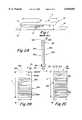
- FIG. 1illustrates a planar inverted F antenna used within radiotelephones.
- FIGS. 2A-2Cillustrate a dual band diversity antenna having a fed radiating element and a parasitic radiating element, according to the present invention.
- FIG. 3is an exemplary resonance curve achievable by a dual band diversity antenna incorporating aspects of the present invention.
- FIG. 4illustrates a dual band diversity antenna, according to the present invention, secured to a shield can of a radiotelephone.
- an antennais a device for transmitting and/or receiving electrical signals.
- a transmitting antennatypically includes a feed assembly that induces or illuminates an aperture or reflecting surface to radiate an electromagnetic field.
- a receiving antennatypically includes an aperture or surface focusing an incident radiation field to a collecting feed, producing an electronic signal proportional to the incident radiation.
- the amount of power radiated from or received by an antennadepends on its aperture area and is described in terms of gain. Radiation patterns for antennas are often plotted using polar coordinates.
- Voltage Standing Wave Ratiorelates to the impedance match of an antenna feed point with the feed line or transmission line. To radiate RF energy with minimum loss, or to pass along received RF energy to the receiver with minimum loss, the impedance of the antenna should be matched to the impedance of the transmission line or feeder.
- Radiotelephonestypically employ a primary antenna which is electrically connected to a transceiver operably associated with a signal processing circuit positioned on an internally disposed printed circuit board.
- the transceiver and the antennaare preferably interconnected such that the respective impedances are substantially "matched,” i.e., electrically tuned to filter out or compensate for undesired antenna impedance components to provide a 50 Ohm (or desired) impedance value at the circuit feed.
- a diversity antennamay be utilized in conjunction with a primary antenna within a radiotelephone to prevent calls from being dropped due to fluctuations in signal strength.
- Signal strengthmay vary as a result of a user moving between cells in a cellular telephone network, a user walking between buildings, interference from stationary objects, and the like.
- Diversity antennasare designed to pick up signals that the main antenna is unable to pick up through spatial, pattern, and bandwidth or gain diversity.
- Diversity antennasmay also be utilized to offset Rayleigh fading, which may include sudden deep fades or losses of signal strength due to multipath phase cancellation.
- a type of diversity antenna well known in the artis the Planar Inverted F Antenna (PIFA) and is illustrated in FIG. 1.
- the illustrated PIFA 10includes a radiating element 12 maintained in spaced apart relationship with a ground plane 14. The radiating element is also grounded to the ground plane 14 as indicated by 16.
- a hot RF connection 17extends from underlying circuitry (not shown) through the ground plane 14 to the radiating element 12 at 18.
- a PIFAis tuned to desired frequencies by adjusting the following parameters which can affect gain and bandwidth: varying the length L of the radiating element 12; varying the gap H between the radiating element 12 and the ground plane 14; and varying the distance D between the ground and hot RF connections.
- Ground plane sizemay also be an important tuning parameter. Other parameters known to those skilled in the art may be adjusted to tune the PIFA, and will not be discussed further.
- the antenna 20includes a dielectric substrate 22, such as a fiberglass circuit board, having first and second opposite surfaces 22a and 22b.
- a particularly preferable material for use as the substrateis an FR4 board which is well known to those having skill in the art of circuit boards.
- various dielectric materialsmay be utilized for the substrate 22.
- the dielectric substrate 22has a dielectric constant between 4.4 and 4.8 for the illustrated embodiment.
- dielectric substrates having different dielectric constantsmay be utilized without departing from the spirit and intent of the present invention.
- Diversity antennasare particularly well suited for combating both Rayleigh (line of sight and one main reflection) and Ricean (multiple reflections) fading.
- the present inventionallows the diversity antenna to reside in a very small mobile radiotelephone and helps when the main antenna enters into a very large fade region.
- the dielectric substrate 22may vary depending on the space limitations of the radiotelephone or other communications device within which the diversity antenna 20 is incorporated. Typically, the dielectric substrate 22 will have a thickness T of between 1.0 and 1.5 millimeters (mm); a width W of between 11 and 22 mm; and a length L of between 21 and 23 mm.
- a layer of copper or other conductive materialis secured to both the first and second substrate surfaces 22a and 22b, and is indicated as 24a and 24b, respectively.
- a preferred conductive materialis copper tape because portions thereof can be removed easily during tuning of the antenna.
- the thickness of the conductive layers 24a, 24b on each respective substrate surface 22a, 22bis between 0.5 ounces (oz) and 1.0 oz copper.
- a ground post 27 and a hot RF feed point 28are electrically connected to the conductive layer 24a, as illustrated in FIG. 2B.
- the locations of the ground post 27 and the hot RF feed point 28 on the substrate first surface conductive layer 24aare selected based upon desired input impedance.
- a coaxial connector 29extends through, but is not electrically connected to, the substrate second surface conductive layer 24b, as illustrated in FIG. 2C.
- the ground post 27 and the hot RF feed point 28are electrically connected to underlying circuitry (not shown) within a radiotelephone via the coaxial connector 29, as will be described below.
- the conductive layer 24b secured to the substrate second surface 22bis a parasitic conductive layer; i.e., it is not electrically connected to other portions of the antenna 20.
- parasitic electromagnetic elementsare coupled to, and "feed off", near-field currents (i.e., currents flowing on a conductive surface exist in a "field” of electromagnetic fields that the currents induce in close proximity to the conductive surface).
- a parasitic antennais an antenna that is not driven directly by an RF source, but rather, is excited by energy radiated by another source. The presence of a parasitic element may change the resonant characteristics of a nearby antenna, allowing the antenna to resonate in more than one band.
- the first and second substrate surfaces 22a, 22b and the respective conductive layers 24a, 24b thereoneach function as respective radiating elements, indicated as 30a and 30b.
- Radiating element 30ais referred to as a "fed” radiating element
- radiating element 30bis referred to as a "parasitic” radiating element.
- the fed and parasitic radiating elements 30a, 30ballow the antenna 20 to be tuned so as to resonate within at least two frequency bands.
- each conductive layer 24a, 24bhas been removed to create meandering electrically conductive patterns for radiating RF energy, indicated as 32a and 32b, respectively.
- the length of each meandering electrically conductive pattern 32a, 32bis a tuning parameter, as is known to those skilled in the art.
- the fed radiating element 30a and the parasitic radiating element 30ballow the antenna 20 to resonate within at least two frequency bands.
- the parasitic radiating element 30bis excited by magnetic fields generated from the fed radiating element 30a.
- the fed radiating element 30a and the parasitic radiating element 30bare preferably configured to produce two different resonant frequencies. Accordingly, the bandwidth of the antenna may be increased compared with an antenna having only a single radiating element.
- VSWRis plotted along the "Y" axis and is indicated as 42.
- Frequencyis plotted along the "X" axis and is indicated as 44.
- the fed radiating element 30a and the parasitic radiating element 30bare configured to resonate at two closely spaced receive bands (Band 1) and (Band 2).
- Band 1extends from frequency f 1 to frequency f 2
- Band 2extends from frequency f 3 to frequency f 4 .
- Band 1 and Band 2are closely spaced and each is below the 2:1 VSWR to facilitate impedance matching.
- the resonance curve 40shows where (in frequency) the match between the antenna and the receiver circuit will result in 0.5 dB or less of loss.
- the represented a dual band diversity antennais made to approach a 1/4--1/4 wave retractable antenna in gain over the two frequency bands.
- the resonance curve 40is adjustable by "tuning" the antenna 20. Tuning includes adjusting and selecting various parameters of the dual band diversity antenna as described below.
- a dual band diversity antenna 20is illustrated in an installed configuration within upper and lower housing portions 60a,60b of a communications device, such as a radiotelephone.
- the housing portions 60a, 60bare configured to enclose the circuit board 54 and diversity antenna 20 as would be understood by one of skill in the art.
- the antenna 20overlies, and is maintained in spaced apart relationship with, a shield can 52.
- the shield can 52overlies a circuit board 54 and provides electromagnetic interference (EMI) shielding for various microelectronic components (not shown) secured to the circuit board.
- the shield can 52has a planar outer surface 53 which serves as a ground plane for the antenna 20.
- a coaxial connector 29provides a pathway for a hot feed element 33 to extend from the circuit board 54 through the shield can aperture 31 and electrically connect with the feed point 28.
- the illustrated coaxial connector 29also provides a pathway for a ground feed element 35 to electrically connect the ground post 27 with the grounded shield can 52.
- the hot feed element 33electrically connects the hot RF feed point 28 with a receiver input and output (not shown), preferably via an RF switch (receive only) (not shown), on the underlying circuit board 54. The RF switch switches out the primary and diversity antennas to the receiver.
- the parasitic radiating element 30b of the antenna 20is maintained in spaced apart generally parallel relationship with the outer surface 53 of the shield can 52.
- Foam 55 or other similar non-conductive materialis preferably placed between the parasitic radiating element 30b and the outer surface 53 of the shield can 52 and serves as means for reducing the effects of vibrations and jarring.
- Tuning parameters for the illustrated diversity antenna 20include, but are not limited to: the length L of the antenna 20; the thickness D 1 of the dielectric substrate 22; the distance D 2 between the shield can 52 and the antenna 20; the distance D 3 between the hot RF feed point 28 and the ground post 27; and the length of the meandering electrically conductive patterns of both the fed radiating element 30a and the parasitic radiating element 30b.
- the dielectric substrate 22 and length of the meandering electrically conductive patternsdefine "electrical length" necessary to radiate a resonance structure. Ground plane, feeds and feed separation are variations of the classical antenna.
Landscapes
- Engineering & Computer Science (AREA)
- Computer Networks & Wireless Communication (AREA)
- Signal Processing (AREA)
- Support Of Aerials (AREA)
- Details Of Aerials (AREA)
- Waveguide Aerials (AREA)
- Variable-Direction Aerials And Aerial Arrays (AREA)
Abstract
Description
The present invention relates generally to antennas, and more particularly to diversity antennas used within communication devices.
Antennas for personal communication devices, such as radiotelephones, may not function adequately when in close proximity to a user during operation, or when a user is moving during operation of a device. Close proximity to objects or movement of a user during operation of a radiotelephone may result in degraded signal quality or fluctuations in signal strength, known as multipath fading. Diversity antennas have been designed to work in conjunction with a radiotelephone's primary antenna to improve signal reception.
Many of the popular hand-held radiotelephones are undergoing miniaturization. Indeed, many of the contemporary models are only 11-12 centimeters in length. Unfortunately, as radiotelephones decrease in size, the amount of internal space therewithin may be reduced correspondingly. A reduced amount of internal space may make it difficult for existing types of diversity antennas to achieve the bandwidth and gain requirements necessary for radiotelephone operation because their size may be correspondingly reduced.
Furthermore, it may be desirable for a diversity antenna to be able to resonate over multiple frequency bands. For example, the Japanese Personal Digital Cellular (PDC) system utilizes two "receive" frequency bands and two "transmit" frequency bands. Accordingly, a diversity antenna within a radiotelephone used in the Japanese PDC system should preferably be able to resonate in each of the two receive frequency bands. Unfortunately, the ability to provide diversity antennas with adequate gain over multiple frequency bands may be presently limited because of size limitations imposed by radiotelephone miniaturization.
It is, therefore, an object of the present invention to provide diversity antennas that can resonate over multiple frequency bands with sufficient gain for use within personal communication devices such as radiotelephones.
It is also an object of the present invention to provide reduced size diversity antennas that can resonate over multiple frequency bands with sufficient gain and that can be installed within the small internal space of miniature radiotelephones.
These and other objects of the present invention are provided by a planar diversity antenna for communications devices, such as radiotelephones, having two radiating elements secured to opposite sides of a dielectric substrate and parasitically coupled to jointly resonate at two adjacent frequency bands. One radiating element, referred to as the "fed" radiating element, has a meandering electrically conductive path with an RF feed point and a ground point thereon. A second radiating element, referred to as the "parasitic" radiating element, has a meandering electrically conductive path thereon. The parasitic radiating element is maintained in a spaced-apart, generally parallel relationship with both the "fed" radiating element and a ground plane.
When a planar diversity antenna according to the present invention is used within a radiotelephone, a shield can overlying the RF circuitry may serve as a ground plane. The planar antenna element is secured within the housing of a radiotelephone such that the parasitic radiating element is in spaced apart parallel relationship with an outer planar surface of the shield can. An aperture in the shield can outer surface allows a hot feed element to extend from the RF circuitry through the shield can aperture and electrically connect with the feed point on the fed radiating element conductive path. A ground feed element electrically connects the ground post on the fed radiating element conductive path with the grounded shield can.
The fed and parasitic radiating elements may have meandering electrically conductive paths with different electrical and physical lengths. Accordingly, the fed and parasitic radiating elements jointly radiate in dual-band resonances. Exemplary adjacent frequency bands include from between 0.810 and 0.828 GHz and between 0.870 and 0.885 GHz.
Diversity antennas according to the present invention may be advantageous because their configuration can allow them to conform to the small space constraints of current radiotelephones and other communication devices while providing adequate gain and bandwidth characteristics. The dual band functionality of diversity antennas incorporating aspects of the present invention may be particularly advantageous in countries, such as Japan, which utilize multiple frequency bands for transmitting and receiving radiotelephone communications. The present invention may be suitable as a diversity antenna for a dual band radiotelephone.
FIG. 1 illustrates a planar inverted F antenna used within radiotelephones.
FIGS. 2A-2C illustrate a dual band diversity antenna having a fed radiating element and a parasitic radiating element, according to the present invention.
FIG. 3 is an exemplary resonance curve achievable by a dual band diversity antenna incorporating aspects of the present invention.
FIG. 4 illustrates a dual band diversity antenna, according to the present invention, secured to a shield can of a radiotelephone.
The present invention now will be described more fully hereinafter with reference to the accompanying drawings, in which preferred embodiments of the invention are shown. This invention may, however, be embodied in many different forms and should not be construed as limited to the embodiments set forth herein; rather, these embodiments are provided so that this disclosure will be thorough and complete, and will fully convey the scope of the invention to those skilled in the art. Like numbers refer to like elements throughout.
As is known to those skilled in the art, an antenna is a device for transmitting and/or receiving electrical signals. A transmitting antenna typically includes a feed assembly that induces or illuminates an aperture or reflecting surface to radiate an electromagnetic field. A receiving antenna typically includes an aperture or surface focusing an incident radiation field to a collecting feed, producing an electronic signal proportional to the incident radiation. The amount of power radiated from or received by an antenna depends on its aperture area and is described in terms of gain. Radiation patterns for antennas are often plotted using polar coordinates. Voltage Standing Wave Ratio (VSWR) relates to the impedance match of an antenna feed point with the feed line or transmission line. To radiate RF energy with minimum loss, or to pass along received RF energy to the receiver with minimum loss, the impedance of the antenna should be matched to the impedance of the transmission line or feeder.
Radiotelephones typically employ a primary antenna which is electrically connected to a transceiver operably associated with a signal processing circuit positioned on an internally disposed printed circuit board. In order to maximize power transfer between the antenna and the transceiver, the transceiver and the antenna are preferably interconnected such that the respective impedances are substantially "matched," i.e., electrically tuned to filter out or compensate for undesired antenna impedance components to provide a 50 Ohm (or desired) impedance value at the circuit feed.
As is well known to those skilled in the art, a diversity antenna may be utilized in conjunction with a primary antenna within a radiotelephone to prevent calls from being dropped due to fluctuations in signal strength. Signal strength may vary as a result of a user moving between cells in a cellular telephone network, a user walking between buildings, interference from stationary objects, and the like. Diversity antennas are designed to pick up signals that the main antenna is unable to pick up through spatial, pattern, and bandwidth or gain diversity. Diversity antennas may also be utilized to offset Rayleigh fading, which may include sudden deep fades or losses of signal strength due to multipath phase cancellation.
A type of diversity antenna well known in the art is the Planar Inverted F Antenna (PIFA) and is illustrated in FIG. 1. The illustratedPIFA 10 includes a radiatingelement 12 maintained in spaced apart relationship with aground plane 14. The radiating element is also grounded to theground plane 14 as indicated by 16. Ahot RF connection 17 extends from underlying circuitry (not shown) through theground plane 14 to theradiating element 12 at 18. A PIFA is tuned to desired frequencies by adjusting the following parameters which can affect gain and bandwidth: varying the length L of theradiating element 12; varying the gap H between theradiating element 12 and theground plane 14; and varying the distance D between the ground and hot RF connections. Ground plane size may also be an important tuning parameter. Other parameters known to those skilled in the art may be adjusted to tune the PIFA, and will not be discussed further.
Referring now to FIGS. 2A-2C a dualband diversity antenna 20 in accordance with a preferred embodiment of the present invention is illustrated. Theantenna 20 includes adielectric substrate 22, such as a fiberglass circuit board, having first and secondopposite surfaces substrate 22. Preferably, thedielectric substrate 22 has a dielectric constant between 4.4 and 4.8 for the illustrated embodiment. However, it is to be understood that dielectric substrates having different dielectric constants may be utilized without departing from the spirit and intent of the present invention.
Diversity antennas, according to the present invention, are particularly well suited for combating both Rayleigh (line of sight and one main reflection) and Ricean (multiple reflections) fading. The present invention allows the diversity antenna to reside in a very small mobile radiotelephone and helps when the main antenna enters into a very large fade region.
Dimensions of thedielectric substrate 22 may vary depending on the space limitations of the radiotelephone or other communications device within which thediversity antenna 20 is incorporated. Typically, thedielectric substrate 22 will have a thickness T of between 1.0 and 1.5 millimeters (mm); a width W of between 11 and 22 mm; and a length L of between 21 and 23 mm.
A layer of copper or other conductive material is secured to both the first and second substrate surfaces 22a and 22b, and is indicated as 24a and 24b, respectively. A preferred conductive material is copper tape because portions thereof can be removed easily during tuning of the antenna. Typically, the thickness of theconductive layers respective substrate surface
Aground post 27 and a hotRF feed point 28 are electrically connected to theconductive layer 24a, as illustrated in FIG. 2B. The locations of theground post 27 and the hotRF feed point 28 on the substrate first surfaceconductive layer 24a are selected based upon desired input impedance. Acoaxial connector 29 extends through, but is not electrically connected to, the substrate second surfaceconductive layer 24b, as illustrated in FIG. 2C. Theground post 27 and the hotRF feed point 28 are electrically connected to underlying circuitry (not shown) within a radiotelephone via thecoaxial connector 29, as will be described below.
Theconductive layer 24b secured to the substratesecond surface 22b is a parasitic conductive layer; i.e., it is not electrically connected to other portions of theantenna 20. As is known to those skilled in the art, parasitic electromagnetic elements are coupled to, and "feed off", near-field currents (i.e., currents flowing on a conductive surface exist in a "field" of electromagnetic fields that the currents induce in close proximity to the conductive surface). A parasitic antenna is an antenna that is not driven directly by an RF source, but rather, is excited by energy radiated by another source. The presence of a parasitic element may change the resonant characteristics of a nearby antenna, allowing the antenna to resonate in more than one band.
As will be described below, the first andsecond substrate surfaces conductive layers element 30b is referred to as a "parasitic" radiating element. As will be described below, the fed andparasitic radiating elements 30a, 30b allow theantenna 20 to be tuned so as to resonate within at least two frequency bands.
Referring to FIGS. 2B and 2C,portions 26a, 26b of eachconductive layer conductive pattern 32a, 32b is a tuning parameter, as is known to those skilled in the art. The fed radiating element 30a and theparasitic radiating element 30b allow theantenna 20 to resonate within at least two frequency bands. Theparasitic radiating element 30b is excited by magnetic fields generated from the fed radiating element 30a. The fed radiating element 30a and theparasitic radiating element 30b are preferably configured to produce two different resonant frequencies. Accordingly, the bandwidth of the antenna may be increased compared with an antenna having only a single radiating element.
Referring now to FIG. 3, anexemplary resonance curve 40 achievable by a dual band diversity antenna, according to the present invention, is illustrated. VSWR is plotted along the "Y" axis and is indicated as 42. Frequency is plotted along the "X" axis and is indicated as 44. As shown by the illustratedresonance curve 40, the fed radiating element 30a and theparasitic radiating element 30b are configured to resonate at two closely spaced receive bands (Band 1) and (Band 2).Band 1 extends from frequency f1 to frequency f2, andBand 2 extends from frequency f3 to frequency f4.Band 1 andBand 2 are closely spaced and each is below the 2:1 VSWR to facilitate impedance matching. Theresonance curve 40 shows where (in frequency) the match between the antenna and the receiver circuit will result in 0.5 dB or less of loss. The represented a dual band diversity antenna is made to approach a 1/4--1/4 wave retractable antenna in gain over the two frequency bands. As is understood by those skilled in the art, theresonance curve 40 is adjustable by "tuning" theantenna 20. Tuning includes adjusting and selecting various parameters of the dual band diversity antenna as described below.
Referring now to FIG. 4, a dualband diversity antenna 20, according to the present invention, is illustrated in an installed configuration within upper andlower housing portions housing portions circuit board 54 anddiversity antenna 20 as would be understood by one of skill in the art. Theantenna 20 overlies, and is maintained in spaced apart relationship with, a shield can 52. The shield can 52 overlies acircuit board 54 and provides electromagnetic interference (EMI) shielding for various microelectronic components (not shown) secured to the circuit board. The shield can 52 has a planarouter surface 53 which serves as a ground plane for theantenna 20.
In the illustrated embodiment, acoaxial connector 29 provides a pathway for ahot feed element 33 to extend from thecircuit board 54 through the shield canaperture 31 and electrically connect with thefeed point 28. The illustratedcoaxial connector 29 also provides a pathway for aground feed element 35 to electrically connect theground post 27 with the grounded shield can 52. As is known to those skilled in the art, thehot feed element 33 electrically connects the hotRF feed point 28 with a receiver input and output (not shown), preferably via an RF switch (receive only) (not shown), on theunderlying circuit board 54. The RF switch switches out the primary and diversity antennas to the receiver.
Theparasitic radiating element 30b of theantenna 20 is maintained in spaced apart generally parallel relationship with theouter surface 53 of the shield can 52.Foam 55 or other similar non-conductive material is preferably placed between theparasitic radiating element 30b and theouter surface 53 of the shield can 52 and serves as means for reducing the effects of vibrations and jarring.
Tuning parameters for the illustrateddiversity antenna 20 include, but are not limited to: the length L of theantenna 20; the thickness D1 of thedielectric substrate 22; the distance D2 between the shield can 52 and theantenna 20; the distance D3 between the hotRF feed point 28 and theground post 27; and the length of the meandering electrically conductive patterns of both the fed radiating element 30a and theparasitic radiating element 30b. Thedielectric substrate 22 and length of the meandering electrically conductive patterns define "electrical length" necessary to radiate a resonance structure. Ground plane, feeds and feed separation are variations of the classical antenna.
The foregoing is illustrative of the present invention and is not to be construed as limiting thereof. Although a few exemplary embodiments of this invention have been described, those skilled in the art will readily appreciate that many modifications are possible in the exemplary embodiments without materially departing from the novel teachings and advantages of this invention. Accordingly, all such modifications are intended to be included within the scope of this invention as defined in the claims. In the claims, means-plus-function clauses are intended to cover the structures described herein as performing the recited function and not only structural equivalents but also equivalent structures. Therefore, it is to be understood that the foregoing is illustrative of the present invention and is not to be construed as limited to the specific embodiments disclosed, and that modifications to the disclosed embodiments, as well as other embodiments, are intended to be included within the scope of the appended claims. The invention is defined by the following claims, with equivalents of the claims to be included therein.
Claims (16)
1. An antenna, comprising:
a dielectric substrate comprising opposite first and second faces;
a first radiating element disposed on said dielectric substrate first face, said first radiating element comprising a first meandering electrically conductive path having an RF feed point and a around post;
a second radiating element disposed on said dielectric substrate second face and capacitively coupled with said first radiating element, said second radiating element comprising a second meandering electrically conductive path, wherein said first and second meandering electrically conductive paths have different lengths;
a hot feed element extending through said dielectric substrate and electrically connected to said RF feed point; and
a ground feed element extending through said dielectric substrate and electrically connected to said ground post, wherein the ground feed element is not in electrical contact with the second radiating element.
2. An antenna according to claim 1 wherein said dielectric substrate has a dielectric constant between 4.4 and 4.8.
3. An antenna according to claim 1 wherein said first and second radiating elements jointly resonate within adjacent frequency bands.
4. An antenna according to claim 3 wherein said adjacent frequency bands are between 0.810 and 0.828 GHz and between 0.870 and 0.885 GHz, respectively.
5. An antenna assembly for a communications device, said antenna assembly comprising:
a ground plane having an aperture therethrough;
a planar antenna in adjacent parallel spaced apart relationship with said ground plane, and wherein said antenna comprises:
a dielectric substrate comprising opposite first and second faces;
a first radiating element disposed on said substrate first face, said first radiating element comprising a first meandering electrically conductive path having an RF feed point and a ground point; and
a second radiating element disposed on said substrate second face and capacitively coupled with said first radiating element, said second radiating element comprising a second meandering electrically conductive path, wherein said first and second meandering electrically conductive paths have different lengths;
a hot feed element extending through said ground plane aperture and electrically connected to said feed point through said dielectric substrate; and
a ground feed element extending from said ground plane and electrically connected to said ground point through said dielectric substrate, wherein the ground feed element is not in electrical contact with the second radiating element.
6. An antenna assembly according to claim 5 wherein said dielectric substrate has a dielectric constant between 4.4 and 4.8.
7. An antenna assembly according to claim 5 wherein said first and second radiating elements jointly resonate within adjacent frequency bands.
8. An antenna assembly according to claim 7 wherein said adjacent frequency bands are between 0.810 and 0.828 GHz and between 0.870 and 0.885 GHz, respectively.
9. A radiotelephone apparatus, comprising:
a housing;
a circuit board disposed within said housing and having a face with electronic components mounted thereon;
a shield can overlying and secured to a portion of said circuit board face, said shield can having a planar outer surface with an aperture formed therethrough;
a planar antenna overlying said shield can outer surface and comprising:
a dielectric substrate comprising opposite first and second faces;
a first radiating element disposed on said substrate first face, said first radiating element comprising a first meandering electrically conductive path having an RF feed point and a ground point; and
a second radiating element disposed on said substrate second face and capacitively coupled with said first radiating element, said second radiating element comprising a second meandering electrically conductive path;
wherein said planar antenna is secured within said housing such that said second radiating element is in spaced apart parallel relationship with said shield can outer surface;
a hot feed element extending from said circuit board through said shield can aperture and electrically connecting said feed point; and
a ground feed element extending from said shield can and electrically connecting said ground point.
10. A radiotelephone apparatus according to claim 9 further comprising means for reducing vibrations, said means positioned between said second radiating element and said shield can outer surface.
11. A radiotelephone apparatus according to claim 9 wherein said first and second meandering electrically conductive paths have different lengths.
12. A radiotelephone apparatus according to claim 9 wherein said dielectric substrate has a dielectric constant between 4.4 and 4.8.
13. A radiotelephone apparatus according to claim 9 wherein said hot feed element extends through said dielectric substrate.
14. A radiotelephone apparatus according to claim 9 wherein said ground feed element extends through said dielectric substrate.
15. A radiotelephone apparatus according to claim 9 wherein said first and second radiating elements jointly resonate within adjacent frequency bands.
16. A radiotelephone apparatus according to claim 15 wherein said adjacent frequency bands are between 0.810 and 0.828 GHz and between 0.870 and 0.885 GHz, respectively.
Priority Applications (10)
| Application Number | Priority Date | Filing Date | Title |
|---|---|---|---|
| US09/026,456US6040803A (en) | 1998-02-19 | 1998-02-19 | Dual band diversity antenna having parasitic radiating element |
| HK01106944.3AHK1036156B (en) | 1998-02-19 | 1999-02-05 | Dual band diversity antenna having parasitic radiating element |
| DE69908305TDE69908305T2 (en) | 1998-02-19 | 1999-02-05 | DOUBLE BAND DIVERSITY ANTENNA WITH PARASITAL RADIATOR ELEMENT |
| JP2000532882AJP4132669B2 (en) | 1998-02-19 | 1999-02-05 | Dual-band diversity antenna with parasitic radiating elements |
| KR1020007009088AKR100605819B1 (en) | 1998-02-19 | 1999-02-05 | Dual band diversity antenna with parasitic radiating elements |
| PCT/US1999/002470WO1999043043A1 (en) | 1998-02-19 | 1999-02-05 | Dual band diversity antenna having parasitic radiating element |
| CNB99803083XACN1147023C (en) | 1998-02-19 | 1999-02-05 | Dual frequency band diversity antenna having papasitic rediating element |
| EP99905762AEP1055266B1 (en) | 1998-02-19 | 1999-02-05 | Dual band diversity antenna having parasitic radiating element |
| AU25851/99AAU2585199A (en) | 1998-02-19 | 1999-02-05 | Dual band diversity antenna having parasitic radiating element |
| TW088102284ATW469667B (en) | 1998-02-19 | 1999-02-12 | Dual band diversity antenna having parasitic radiating element |
Applications Claiming Priority (1)
| Application Number | Priority Date | Filing Date | Title |
|---|---|---|---|
| US09/026,456US6040803A (en) | 1998-02-19 | 1998-02-19 | Dual band diversity antenna having parasitic radiating element |
Publications (1)
| Publication Number | Publication Date |
|---|---|
| US6040803Atrue US6040803A (en) | 2000-03-21 |
Family
ID=21831928
Family Applications (1)
| Application Number | Title | Priority Date | Filing Date |
|---|---|---|---|
| US09/026,456Expired - LifetimeUS6040803A (en) | 1998-02-19 | 1998-02-19 | Dual band diversity antenna having parasitic radiating element |
Country Status (9)
| Country | Link |
|---|---|
| US (1) | US6040803A (en) |
| EP (1) | EP1055266B1 (en) |
| JP (1) | JP4132669B2 (en) |
| KR (1) | KR100605819B1 (en) |
| CN (1) | CN1147023C (en) |
| AU (1) | AU2585199A (en) |
| DE (1) | DE69908305T2 (en) |
| TW (1) | TW469667B (en) |
| WO (1) | WO1999043043A1 (en) |
Cited By (87)
| Publication number | Priority date | Publication date | Assignee | Title |
|---|---|---|---|---|
| US6124831A (en)* | 1999-07-22 | 2000-09-26 | Ericsson Inc. | Folded dual frequency band antennas for wireless communicators |
| US6181282B1 (en)* | 2000-01-28 | 2001-01-30 | Tyco Electronics Corporation | Antenna and method of making same |
| US6204826B1 (en)* | 1999-07-22 | 2001-03-20 | Ericsson Inc. | Flat dual frequency band antennas for wireless communicators |
| US6229487B1 (en)* | 2000-02-24 | 2001-05-08 | Ericsson Inc. | Inverted-F antennas having non-linear conductive elements and wireless communicators incorporating the same |
| US6255999B1 (en)* | 1999-04-28 | 2001-07-03 | The Whitaker Corporation | Antenna element having a zig zag pattern |
| US6292144B1 (en)* | 1999-10-15 | 2001-09-18 | Northwestern University | Elongate radiator conformal antenna for portable communication devices |
| WO2001093374A1 (en)* | 2000-05-31 | 2001-12-06 | Bae Systems Information And Electronic Systems Integration Inc. | Multi-layer, wideband meander line loaded antenna |
| US6333716B1 (en)* | 1998-12-22 | 2001-12-25 | Nokia Mobile Limited | Method for manufacturing an antenna body for a phone |
| US6337662B1 (en) | 1997-04-30 | 2002-01-08 | Moteco Ab | Antenna for radio communications apparatus |
| US6366243B1 (en)* | 1998-10-30 | 2002-04-02 | Filtronic Lk Oy | Planar antenna with two resonating frequencies |
| WO2001048858A3 (en)* | 1999-12-14 | 2002-05-02 | Rangestar Wireless Inc | Low sar broadband antenna assembly |
| US6426722B1 (en) | 2000-03-08 | 2002-07-30 | Hrl Laboratories, Llc | Polarization converting radio frequency reflecting surface |
| US20020164963A1 (en)* | 2001-04-09 | 2002-11-07 | Tehrani Ardavan Maleki | Method and system for providing antenna diversity |
| US6483481B1 (en) | 2000-11-14 | 2002-11-19 | Hrl Laboratories, Llc | Textured surface having high electromagnetic impedance in multiple frequency bands |
| US6483480B1 (en)* | 2000-03-29 | 2002-11-19 | Hrl Laboratories, Llc | Tunable impedance surface |
| US6518931B1 (en) | 2000-03-15 | 2003-02-11 | Hrl Laboratories, Llc | Vivaldi cloverleaf antenna |
| US20030030594A1 (en)* | 2001-07-30 | 2003-02-13 | Thomas Larry | Small controlled parasitic antenna system and method for controlling same to optimally improve signal quality |
| US6529749B1 (en)* | 2000-05-22 | 2003-03-04 | Ericsson Inc. | Convertible dipole/inverted-F antennas and wireless communicators incorporating the same |
| US6538621B1 (en) | 2000-03-29 | 2003-03-25 | Hrl Laboratories, Llc | Tunable impedance surface |
| US6545647B1 (en) | 2001-07-13 | 2003-04-08 | Hrl Laboratories, Llc | Antenna system for communicating simultaneously with a satellite and a terrestrial system |
| US6552696B1 (en) | 2000-03-29 | 2003-04-22 | Hrl Laboratories, Llc | Electronically tunable reflector |
| WO2003049321A1 (en)* | 2001-12-06 | 2003-06-12 | Koninklijke Philips Electronics N.V. | Parasitic elements diversity antenna |
| US20030174093A1 (en)* | 2000-08-11 | 2003-09-18 | Stefan Huber | Antenna arrangement on a mobile communication terminal, in particular a mobile telephone |
| US6639560B1 (en)* | 2002-04-29 | 2003-10-28 | Centurion Wireless Technologies, Inc. | Single feed tri-band PIFA with parasitic element |
| US6646607B2 (en)* | 2001-06-08 | 2003-11-11 | International Business Machines Corporation | Antenna system, transceiver, electrical equipment, and computer terminal |
| US20030227351A1 (en)* | 2002-05-15 | 2003-12-11 | Hrl Laboratories, Llc | Single-pole multi-throw switch having low parasitic reactance, and an antenna incorporating the same |
| GB2389964A (en)* | 2002-06-19 | 2003-12-24 | Harada Ind | Multi-band vehicular blade antenna |
| US6670921B2 (en) | 2001-07-13 | 2003-12-30 | Hrl Laboratories, Llc | Low-cost HDMI-D packaging technique for integrating an efficient reconfigurable antenna array with RF MEMS switches and a high impedance surface |
| FR2842951A1 (en)* | 2002-07-26 | 2004-01-30 | Socapex Amphenol | LOW THICKNESS PLATE ANTENNA |
| US20040046694A1 (en)* | 2002-03-14 | 2004-03-11 | Tantivy Communications, Inc. | Mobile communication handset with adaptive antenna array |
| US6724345B2 (en)* | 2002-04-22 | 2004-04-20 | Kyocera Wirless Corp. | Antenna with periodic electromagnetic mode suppression structures and method for same |
| US20040084207A1 (en)* | 2001-07-13 | 2004-05-06 | Hrl Laboratories, Llc | Molded high impedance surface and a method of making same |
| US20040135649A1 (en)* | 2002-05-15 | 2004-07-15 | Sievenpiper Daniel F | Single-pole multi-throw switch having low parasitic reactance, and an antenna incorporating the same |
| US20040150569A1 (en)* | 2002-03-08 | 2004-08-05 | Tantivy Communications, Inc. | Adaptive receive and omnidirectional transmit antenna array |
| WO2004025776A3 (en)* | 2002-09-10 | 2004-08-26 | Motorola Inc | Dual grounded internal antenna |
| US20040198293A1 (en)* | 2002-12-17 | 2004-10-07 | Sadler Robert A. | Multi-band, inverted-f antenna with capacitively created resonance, and radio terminal using same |
| US6812903B1 (en) | 2000-03-14 | 2004-11-02 | Hrl Laboratories, Llc | Radio frequency aperture |
| US20040227668A1 (en)* | 2003-05-12 | 2004-11-18 | Hrl Laboratories, Llc | Steerable leaky wave antenna capable of both forward and backward radiation |
| US20040227678A1 (en)* | 2003-05-12 | 2004-11-18 | Hrl Laboratories, Llc | Compact tunable antenna |
| US20040227667A1 (en)* | 2003-05-12 | 2004-11-18 | Hrl Laboratories, Llc | Meta-element antenna and array |
| US20040227583A1 (en)* | 2003-05-12 | 2004-11-18 | Hrl Laboratories, Llc | RF MEMS switch with integrated impedance matching structure |
| US20040246182A1 (en)* | 2003-06-05 | 2004-12-09 | Kuo-Cheng Chen | Planar inverted f antenna with asymmetric or symmetric perturbations |
| US20040263408A1 (en)* | 2003-05-12 | 2004-12-30 | Hrl Laboratories, Llc | Adaptive beam forming antenna system using a tunable impedance surface |
| US20040263407A1 (en)* | 2003-01-16 | 2004-12-30 | Susumu Inatsugu | Antenna |
| US20050024287A1 (en)* | 2003-05-29 | 2005-02-03 | Young-Min Jo | Radio frequency identification tag |
| US20050030239A1 (en)* | 2002-07-26 | 2005-02-10 | Amphenol Socapex | Antenna of small dimensions |
| US20050088358A1 (en)* | 2002-07-29 | 2005-04-28 | Toyon Research Corporation | Reconfigurable parasitic control for antenna arrays and subarrays |
| US20050110688A1 (en)* | 1999-09-20 | 2005-05-26 | Baliarda Carles P. | Multilevel antennae |
| US20050195112A1 (en)* | 2000-01-19 | 2005-09-08 | Baliarda Carles P. | Space-filling miniature antennas |
| EP1547195A4 (en)* | 2002-09-19 | 2005-11-02 | Topcon Gps Llc | ANTENNA STRUCTURES FOR REDUCING THE EFFECTS OF MULTIVOIE RADIO SIGNALS |
| US20060055605A1 (en)* | 2000-12-14 | 2006-03-16 | Asher Peled | Cavity antenna with reactive surface loading |
| US20060097928A1 (en)* | 2004-11-05 | 2006-05-11 | Hitachi Cable, Ltd. | Small-sized antenna |
| GB2425659A (en)* | 2005-04-29 | 2006-11-01 | Motorola Inc | Planar antenna with elements on both sides of supporting substrate |
| US7154451B1 (en) | 2004-09-17 | 2006-12-26 | Hrl Laboratories, Llc | Large aperture rectenna based on planar lens structures |
| US20060290572A1 (en)* | 2005-06-28 | 2006-12-28 | Chan Yiu K | Antenna system |
| US20070008224A1 (en)* | 2005-07-11 | 2007-01-11 | Wistron Neweb Corp. | Antenna |
| US20070176835A1 (en)* | 2003-06-12 | 2007-08-02 | Yihong Qi | Multiple-element antenna with floating antenna element |
| US20070211403A1 (en)* | 2003-12-05 | 2007-09-13 | Hrl Laboratories, Llc | Molded high impedance surface |
| US7307589B1 (en) | 2005-12-29 | 2007-12-11 | Hrl Laboratories, Llc | Large-scale adaptive surface sensor arrays |
| US20080143607A1 (en)* | 2006-12-18 | 2008-06-19 | Samsung Electronics Co., Ltd. | Concurrent mode antenna system |
| US20080191945A1 (en)* | 2005-07-22 | 2008-08-14 | Kazunari Taki | Antenna, and radio-frequency identification tag |
| US20080198082A1 (en)* | 2005-05-13 | 2008-08-21 | Fractus, S.A. | Antenna Diversity System and Slot Antenna Component |
| US7456803B1 (en) | 2003-05-12 | 2008-11-25 | Hrl Laboratories, Llc | Large aperture rectenna based on planar lens structures |
| US20090093286A1 (en)* | 2006-05-23 | 2009-04-09 | Research In Motion Limited | Mobile wireless communications device with reduced interfering rf energy into rf metal shield secured on circuit board |
| US20100109955A1 (en)* | 2007-03-30 | 2010-05-06 | Jaume Anguera | Wireless device including a multiband antenna system |
| US7868829B1 (en) | 2008-03-21 | 2011-01-11 | Hrl Laboratories, Llc | Reflectarray |
| US20110128193A1 (en)* | 2009-12-02 | 2011-06-02 | Mitsumi Electric Co., Ltd. | Card device for wireless communication |
| US7999749B2 (en)* | 2008-10-23 | 2011-08-16 | Sony Ericsson Mobile Communications Ab | Antenna assembly |
| FR2958458A1 (en)* | 2010-04-02 | 2011-10-07 | Senseor | Antenna i.e. meandered planar inverted F-type reversible antenna, for use in e.g. portable telephone, has radiating plane including slot whose dimensions are different from than that of other plane to operate in one of frequency ranges |
| CN101299485B (en)* | 2007-05-01 | 2012-02-01 | 佛山市顺德区顺达电脑厂有限公司 | Coupled antenna with multi-frequency band resonance segment antenna pattern |
| US8212739B2 (en) | 2007-05-15 | 2012-07-03 | Hrl Laboratories, Llc | Multiband tunable impedance surface |
| US20120169550A1 (en)* | 2008-01-04 | 2012-07-05 | Schlub Robert W | Antenna isolation for portable electronic devices |
| US8228243B1 (en)* | 2009-09-30 | 2012-07-24 | The United States Of America As Represented By The Secretary Of The Navy | Parallel plate antenna |
| US8436785B1 (en) | 2010-11-03 | 2013-05-07 | Hrl Laboratories, Llc | Electrically tunable surface impedance structure with suppressed backward wave |
| US20130141292A1 (en)* | 2007-08-20 | 2013-06-06 | Ethertronics, Inc. | Multi-antenna module containing active elements and control circuits for wireless systems |
| US20130162489A1 (en)* | 2001-10-16 | 2013-06-27 | Ramiro Quintero Illera | Multiband antenna |
| US8738103B2 (en) | 2006-07-18 | 2014-05-27 | Fractus, S.A. | Multiple-body-configuration multimedia and smartphone multifunction wireless devices |
| US8982011B1 (en) | 2011-09-23 | 2015-03-17 | Hrl Laboratories, Llc | Conformal antennas for mitigation of structural blockage |
| US8994609B2 (en) | 2011-09-23 | 2015-03-31 | Hrl Laboratories, Llc | Conformal surface wave feed |
| US20160190677A1 (en)* | 2014-12-29 | 2016-06-30 | Merry Electronics (Shenzhen) Co., Ltd. | Coupling-type grating antenna |
| US9466887B2 (en) | 2010-11-03 | 2016-10-11 | Hrl Laboratories, Llc | Low cost, 2D, electronically-steerable, artificial-impedance-surface antenna |
| US20170301998A1 (en)* | 2016-04-19 | 2017-10-19 | Ethertronics, Inc. | Low profile antenna system |
| US20170373393A1 (en)* | 2016-06-27 | 2017-12-28 | Intel IP Corporation | Frequency reconfigurable antenna decoupling for wireless communication |
| US9899738B2 (en) | 2013-08-20 | 2018-02-20 | Canon Kabushiki Kaisha | Antenna |
| US20180337441A1 (en)* | 2008-03-05 | 2018-11-22 | Ethertronics, Inc. | Antenna And Method For Steering Antenna Beam Direction For Wifi Applications |
| WO2020190926A1 (en)* | 2019-03-21 | 2020-09-24 | Avx Antenna, Inc. D/B/A Ethertronics, Inc. | Multi-mode antenna system |
| US11031688B2 (en) | 2017-11-03 | 2021-06-08 | Dell Products, Lp | System and method for operating an antenna adaptation controller module |
Families Citing this family (24)
| Publication number | Priority date | Publication date | Assignee | Title |
|---|---|---|---|---|
| US6326921B1 (en) | 2000-03-14 | 2001-12-04 | Telefonaktiebolaget Lm Ericsson (Publ) | Low profile built-in multi-band antenna |
| DE60137272D1 (en) | 2000-11-22 | 2009-02-12 | Panasonic Corp | Built-in antenna for a mobile radio |
| GB2370419A (en)* | 2000-12-19 | 2002-06-26 | Nokia Mobile Phones Ltd | Dual mode antenna |
| US6771221B2 (en)* | 2002-01-17 | 2004-08-03 | Harris Corporation | Enhanced bandwidth dual layer current sheet antenna |
| KR20030063752A (en)* | 2002-01-23 | 2003-07-31 | 김봉용 | Flat type antenna |
| WO2004057698A2 (en)* | 2002-12-17 | 2004-07-08 | Ethertronics, Inc. | Antennas with reduced space and improved performance |
| JP4508826B2 (en)* | 2003-11-04 | 2010-07-21 | ミツミ電機株式会社 | Patch antenna |
| KR100595679B1 (en)* | 2004-10-15 | 2006-07-03 | 엘지전자 주식회사 | Broadband antenna of mobile communication terminal |
| CN100356629C (en)* | 2005-07-01 | 2007-12-19 | 清华大学 | Mobile-terminal multi-antenna system |
| US7183981B1 (en)* | 2005-09-02 | 2007-02-27 | Arcadyan Technology Corporation | Monopole antenna |
| KR100732666B1 (en)* | 2005-12-16 | 2007-06-27 | 삼성전자주식회사 | Mobile communication terminal equipped with a plurality of antennas |
| KR100773143B1 (en)* | 2006-04-25 | 2007-11-02 | (주)파트론 | Broadband Antenna Using Couple Patch and Its Broadband Characteristics Implementation Method |
| GB2439760B (en)* | 2006-07-03 | 2008-10-15 | Motorola Inc | Antenna Apparatus |
| JP2008022123A (en) | 2006-07-11 | 2008-01-31 | Samsung Electronics Co Ltd | Antenna device |
| CN101188328B (en)* | 2006-11-15 | 2011-06-01 | 启碁科技股份有限公司 | Flat Small Digital TV Antenna |
| KR100810384B1 (en)* | 2006-12-05 | 2008-03-04 | 삼성전자주식회사 | Built-in antenna device of mobile terminal |
| KR100886488B1 (en)* | 2007-02-15 | 2009-03-05 | 스카이크로스 인코포레이티드 | Antenna for receiving digital multimedia broadcasting |
| CN101299482B (en)* | 2007-05-01 | 2012-09-05 | 佛山市顺德区顺达电脑厂有限公司 | Antenna structure of built-in resonant circuit |
| US7932864B2 (en) | 2008-07-15 | 2011-04-26 | Research In Motion Limited | Mobile wireless communications device with antenna contact having reduced RF inductance |
| ATE480025T1 (en)* | 2008-07-15 | 2010-09-15 | Research In Motion Ltd | MOBILE WIRELESS COMMUNICATION DEVICE WITH ANTENNA CONTACT AND REDUCED RF INDUCTIVITY |
| WO2010016768A1 (en)* | 2008-08-04 | 2010-02-11 | Cellmate As | Means for protecting a user from emf emissions from devices such as mobile phones |
| JP5515696B2 (en)* | 2009-12-02 | 2014-06-11 | ミツミ電機株式会社 | Card device |
| EP3261171A4 (en)* | 2015-02-19 | 2018-08-29 | Tokyo Cosmos Electric Co., Ltd. | Antenna and communication device |
| CN106374212B (en)* | 2016-11-09 | 2023-05-05 | 广东工业大学 | A Compact High Isolation MIMO Antenna |
Citations (13)
| Publication number | Priority date | Publication date | Assignee | Title |
|---|---|---|---|---|
| US4401988A (en)* | 1981-08-28 | 1983-08-30 | The United States Of America As Represented By The Secretary Of The Navy | Coupled multilayer microstrip antenna |
| US4619001A (en)* | 1983-08-02 | 1986-10-21 | Matsushita Electric Industrial Co., Ltd. | Tuning systems on dielectric substrates |
| US4700194A (en)* | 1984-09-17 | 1987-10-13 | Matsushita Electric Industrial Co., Ltd. | Small antenna |
| US4860020A (en)* | 1987-04-30 | 1989-08-22 | The Aerospace Corporation | Compact, wideband antenna system |
| JPH0435207A (en)* | 1990-05-28 | 1992-02-06 | Mitsubishi Electric Corp | Antenna system |
| GB2260226A (en)* | 1991-10-02 | 1993-04-07 | Murata Manufacturing Co | Surface mountable electronic shield case and substrate |
| WO1993012559A1 (en)* | 1991-12-11 | 1993-06-24 | SIEMENS AKTIENGESELLSCHAFT öSTERREICH | Aerial arrangement, especially for communications terminals |
| US5365246A (en)* | 1989-07-27 | 1994-11-15 | Siemens Aktiengesellschaft | Transmitting and/or receiving arrangement for portable appliances |
| WO1996027219A1 (en)* | 1995-02-27 | 1996-09-06 | The Chinese University Of Hong Kong | Meandering inverted-f antenna |
| US5559524A (en)* | 1991-03-18 | 1996-09-24 | Hitachi, Ltd. | Antenna system including a plurality of meander conductors for a portable radio apparatus |
| WO1997049141A1 (en)* | 1996-06-15 | 1997-12-24 | Allgon Ab | Meander antenna device |
| WO1998049742A1 (en)* | 1997-04-30 | 1998-11-05 | Moteco Ab | An antenna for a radio communications apparatus |
| US5898404A (en)* | 1995-12-22 | 1999-04-27 | Industrial Technology Research Institute | Non-coplanar resonant element printed circuit board antenna |
- 1998
- 1998-02-19USUS09/026,456patent/US6040803A/ennot_activeExpired - Lifetime
- 1999
- 1999-02-05EPEP99905762Apatent/EP1055266B1/ennot_activeExpired - Lifetime
- 1999-02-05WOPCT/US1999/002470patent/WO1999043043A1/enactiveIP Right Grant
- 1999-02-05KRKR1020007009088Apatent/KR100605819B1/ennot_activeExpired - Fee Related
- 1999-02-05DEDE69908305Tpatent/DE69908305T2/ennot_activeExpired - Lifetime
- 1999-02-05JPJP2000532882Apatent/JP4132669B2/ennot_activeExpired - Lifetime
- 1999-02-05AUAU25851/99Apatent/AU2585199A/ennot_activeAbandoned
- 1999-02-05CNCNB99803083XApatent/CN1147023C/ennot_activeExpired - Fee Related
- 1999-02-12TWTW088102284Apatent/TW469667B/ennot_activeIP Right Cessation
Patent Citations (13)
| Publication number | Priority date | Publication date | Assignee | Title |
|---|---|---|---|---|
| US4401988A (en)* | 1981-08-28 | 1983-08-30 | The United States Of America As Represented By The Secretary Of The Navy | Coupled multilayer microstrip antenna |
| US4619001A (en)* | 1983-08-02 | 1986-10-21 | Matsushita Electric Industrial Co., Ltd. | Tuning systems on dielectric substrates |
| US4700194A (en)* | 1984-09-17 | 1987-10-13 | Matsushita Electric Industrial Co., Ltd. | Small antenna |
| US4860020A (en)* | 1987-04-30 | 1989-08-22 | The Aerospace Corporation | Compact, wideband antenna system |
| US5365246A (en)* | 1989-07-27 | 1994-11-15 | Siemens Aktiengesellschaft | Transmitting and/or receiving arrangement for portable appliances |
| JPH0435207A (en)* | 1990-05-28 | 1992-02-06 | Mitsubishi Electric Corp | Antenna system |
| US5559524A (en)* | 1991-03-18 | 1996-09-24 | Hitachi, Ltd. | Antenna system including a plurality of meander conductors for a portable radio apparatus |
| GB2260226A (en)* | 1991-10-02 | 1993-04-07 | Murata Manufacturing Co | Surface mountable electronic shield case and substrate |
| WO1993012559A1 (en)* | 1991-12-11 | 1993-06-24 | SIEMENS AKTIENGESELLSCHAFT öSTERREICH | Aerial arrangement, especially for communications terminals |
| WO1996027219A1 (en)* | 1995-02-27 | 1996-09-06 | The Chinese University Of Hong Kong | Meandering inverted-f antenna |
| US5898404A (en)* | 1995-12-22 | 1999-04-27 | Industrial Technology Research Institute | Non-coplanar resonant element printed circuit board antenna |
| WO1997049141A1 (en)* | 1996-06-15 | 1997-12-24 | Allgon Ab | Meander antenna device |
| WO1998049742A1 (en)* | 1997-04-30 | 1998-11-05 | Moteco Ab | An antenna for a radio communications apparatus |
Non-Patent Citations (3)
| Title |
|---|
| PCT International Search Report, PCT International Application No. PCT/US99/02470 (May 28, 1999).* |
| Wong et al., Modified planar inverted F antenna, Electronics Letters, vol. 34, No. 1 pp. 7 8 (Aug. 1, 1998).* |
| Wong et al., Modified planar inverted F antenna, Electronics Letters, vol. 34, No. 1 pp. 7-8 (Aug. 1, 1998). |
Cited By (195)
| Publication number | Priority date | Publication date | Assignee | Title |
|---|---|---|---|---|
| US6509879B2 (en)* | 1997-04-30 | 2003-01-21 | Moteco Ab | Antenna for a radio communications apparatus |
| US6337662B1 (en) | 1997-04-30 | 2002-01-08 | Moteco Ab | Antenna for radio communications apparatus |
| US6366243B1 (en)* | 1998-10-30 | 2002-04-02 | Filtronic Lk Oy | Planar antenna with two resonating frequencies |
| US6333716B1 (en)* | 1998-12-22 | 2001-12-25 | Nokia Mobile Limited | Method for manufacturing an antenna body for a phone |
| US6255999B1 (en)* | 1999-04-28 | 2001-07-03 | The Whitaker Corporation | Antenna element having a zig zag pattern |
| US6124831A (en)* | 1999-07-22 | 2000-09-26 | Ericsson Inc. | Folded dual frequency band antennas for wireless communicators |
| US6204826B1 (en)* | 1999-07-22 | 2001-03-20 | Ericsson Inc. | Flat dual frequency band antennas for wireless communicators |
| US8009111B2 (en) | 1999-09-20 | 2011-08-30 | Fractus, S.A. | Multilevel antennae |
| US8154463B2 (en) | 1999-09-20 | 2012-04-10 | Fractus, S.A. | Multilevel antennae |
| US9054421B2 (en) | 1999-09-20 | 2015-06-09 | Fractus, S.A. | Multilevel antennae |
| US9240632B2 (en) | 1999-09-20 | 2016-01-19 | Fractus, S.A. | Multilevel antennae |
| US9362617B2 (en) | 1999-09-20 | 2016-06-07 | Fractus, S.A. | Multilevel antennae |
| US9761934B2 (en) | 1999-09-20 | 2017-09-12 | Fractus, S.A. | Multilevel antennae |
| US10056682B2 (en) | 1999-09-20 | 2018-08-21 | Fractus, S.A. | Multilevel antennae |
| US8154462B2 (en) | 1999-09-20 | 2012-04-10 | Fractus, S.A. | Multilevel antennae |
| US20060290573A1 (en)* | 1999-09-20 | 2006-12-28 | Carles Puente Baliarda | Multilevel antennae |
| US8330659B2 (en) | 1999-09-20 | 2012-12-11 | Fractus, S.A. | Multilevel antennae |
| US20050110688A1 (en)* | 1999-09-20 | 2005-05-26 | Baliarda Carles P. | Multilevel antennae |
| US20090167625A1 (en)* | 1999-09-20 | 2009-07-02 | Fractus, S.A. | Multilevel antennae |
| US7123208B2 (en) | 1999-09-20 | 2006-10-17 | Fractus, S.A. | Multilevel antennae |
| US8941541B2 (en) | 1999-09-20 | 2015-01-27 | Fractus, S.A. | Multilevel antennae |
| US20050259009A1 (en)* | 1999-09-20 | 2005-11-24 | Carles Puente Baliarda | Multilevel antennae |
| US8976069B2 (en) | 1999-09-20 | 2015-03-10 | Fractus, S.A. | Multilevel antennae |
| US7528782B2 (en) | 1999-09-20 | 2009-05-05 | Fractus, S.A. | Multilevel antennae |
| US9000985B2 (en) | 1999-09-20 | 2015-04-07 | Fractus, S.A. | Multilevel antennae |
| US7394432B2 (en) | 1999-09-20 | 2008-07-01 | Fractus, S.A. | Multilevel antenna |
| US7505007B2 (en) | 1999-09-20 | 2009-03-17 | Fractus, S.A. | Multi-level antennae |
| US7015868B2 (en) | 1999-09-20 | 2006-03-21 | Fractus, S.A. | Multilevel Antennae |
| US7397431B2 (en) | 1999-09-20 | 2008-07-08 | Fractus, S.A. | Multilevel antennae |
| US6292144B1 (en)* | 1999-10-15 | 2001-09-18 | Northwestern University | Elongate radiator conformal antenna for portable communication devices |
| US6509882B2 (en)* | 1999-12-14 | 2003-01-21 | Tyco Electronics Logistics Ag | Low SAR broadband antenna assembly |
| WO2001048858A3 (en)* | 1999-12-14 | 2002-05-02 | Rangestar Wireless Inc | Low sar broadband antenna assembly |
| US20050195112A1 (en)* | 2000-01-19 | 2005-09-08 | Baliarda Carles P. | Space-filling miniature antennas |
| US8558741B2 (en) | 2000-01-19 | 2013-10-15 | Fractus, S.A. | Space-filling miniature antennas |
| US7554490B2 (en) | 2000-01-19 | 2009-06-30 | Fractus, S.A. | Space-filling miniature antennas |
| US8471772B2 (en) | 2000-01-19 | 2013-06-25 | Fractus, S.A. | Space-filling miniature antennas |
| US20050231427A1 (en)* | 2000-01-19 | 2005-10-20 | Carles Puente Baliarda | Space-filling miniature antennas |
| US8212726B2 (en) | 2000-01-19 | 2012-07-03 | Fractus, Sa | Space-filling miniature antennas |
| US7164386B2 (en) | 2000-01-19 | 2007-01-16 | Fractus, S.A. | Space-filling miniature antennas |
| US20050264453A1 (en)* | 2000-01-19 | 2005-12-01 | Baliarda Carles P | Space-filling miniature antennas |
| US7202822B2 (en) | 2000-01-19 | 2007-04-10 | Fractus, S.A. | Space-filling miniature antennas |
| US8610627B2 (en) | 2000-01-19 | 2013-12-17 | Fractus, S.A. | Space-filling miniature antennas |
| US7148850B2 (en) | 2000-01-19 | 2006-12-12 | Fractus, S.A. | Space-filling miniature antennas |
| US8207893B2 (en) | 2000-01-19 | 2012-06-26 | Fractus, S.A. | Space-filling miniature antennas |
| US9331382B2 (en) | 2000-01-19 | 2016-05-03 | Fractus, S.A. | Space-filling miniature antennas |
| US10355346B2 (en) | 2000-01-19 | 2019-07-16 | Fractus, S.A. | Space-filling miniature antennas |
| US6181282B1 (en)* | 2000-01-28 | 2001-01-30 | Tyco Electronics Corporation | Antenna and method of making same |
| US6229487B1 (en)* | 2000-02-24 | 2001-05-08 | Ericsson Inc. | Inverted-F antennas having non-linear conductive elements and wireless communicators incorporating the same |
| US6426722B1 (en) | 2000-03-08 | 2002-07-30 | Hrl Laboratories, Llc | Polarization converting radio frequency reflecting surface |
| US6812903B1 (en) | 2000-03-14 | 2004-11-02 | Hrl Laboratories, Llc | Radio frequency aperture |
| US6518931B1 (en) | 2000-03-15 | 2003-02-11 | Hrl Laboratories, Llc | Vivaldi cloverleaf antenna |
| US6483480B1 (en)* | 2000-03-29 | 2002-11-19 | Hrl Laboratories, Llc | Tunable impedance surface |
| US6538621B1 (en) | 2000-03-29 | 2003-03-25 | Hrl Laboratories, Llc | Tunable impedance surface |
| US6552696B1 (en) | 2000-03-29 | 2003-04-22 | Hrl Laboratories, Llc | Electronically tunable reflector |
| US6529749B1 (en)* | 2000-05-22 | 2003-03-04 | Ericsson Inc. | Convertible dipole/inverted-F antennas and wireless communicators incorporating the same |
| US6373440B2 (en) | 2000-05-31 | 2002-04-16 | Bae Systems Information And Electronic Systems Integration, Inc. | Multi-layer, wideband meander line loaded antenna |
| WO2001093374A1 (en)* | 2000-05-31 | 2001-12-06 | Bae Systems Information And Electronic Systems Integration Inc. | Multi-layer, wideband meander line loaded antenna |
| US20030174093A1 (en)* | 2000-08-11 | 2003-09-18 | Stefan Huber | Antenna arrangement on a mobile communication terminal, in particular a mobile telephone |
| US6483481B1 (en) | 2000-11-14 | 2002-11-19 | Hrl Laboratories, Llc | Textured surface having high electromagnetic impedance in multiple frequency bands |
| US20060055605A1 (en)* | 2000-12-14 | 2006-03-16 | Asher Peled | Cavity antenna with reactive surface loading |
| US20020164963A1 (en)* | 2001-04-09 | 2002-11-07 | Tehrani Ardavan Maleki | Method and system for providing antenna diversity |
| US6961545B2 (en) | 2001-04-09 | 2005-11-01 | Atheros Communications, Inc. | Method and system for providing antenna diversity |
| US6646607B2 (en)* | 2001-06-08 | 2003-11-11 | International Business Machines Corporation | Antenna system, transceiver, electrical equipment, and computer terminal |
| US7197800B2 (en) | 2001-07-13 | 2007-04-03 | Hrl Laboratories, Llc | Method of making a high impedance surface |
| US6670921B2 (en) | 2001-07-13 | 2003-12-30 | Hrl Laboratories, Llc | Low-cost HDMI-D packaging technique for integrating an efficient reconfigurable antenna array with RF MEMS switches and a high impedance surface |
| US6545647B1 (en) | 2001-07-13 | 2003-04-08 | Hrl Laboratories, Llc | Antenna system for communicating simultaneously with a satellite and a terrestrial system |
| US20040084207A1 (en)* | 2001-07-13 | 2004-05-06 | Hrl Laboratories, Llc | Molded high impedance surface and a method of making same |
| US6739028B2 (en) | 2001-07-13 | 2004-05-25 | Hrl Laboratories, Llc | Molded high impedance surface and a method of making same |
| US20030030594A1 (en)* | 2001-07-30 | 2003-02-13 | Thomas Larry | Small controlled parasitic antenna system and method for controlling same to optimally improve signal quality |
| US6876337B2 (en) | 2001-07-30 | 2005-04-05 | Toyon Research Corporation | Small controlled parasitic antenna system and method for controlling same to optimally improve signal quality |
| US20130162489A1 (en)* | 2001-10-16 | 2013-06-27 | Ramiro Quintero Illera | Multiband antenna |
| US8723742B2 (en)* | 2001-10-16 | 2014-05-13 | Fractus, S.A. | Multiband antenna |
| US6917338B2 (en)* | 2001-12-06 | 2005-07-12 | Koninklijke Philips Electronics N.V. | Parasitic elements diversity antenna |
| WO2003049321A1 (en)* | 2001-12-06 | 2003-06-12 | Koninklijke Philips Electronics N.V. | Parasitic elements diversity antenna |
| US20050064824A1 (en)* | 2001-12-06 | 2005-03-24 | Jozef Reinerus Maria Bergervoet | Parasitic elements diversity antenna |
| US20040150569A1 (en)* | 2002-03-08 | 2004-08-05 | Tantivy Communications, Inc. | Adaptive receive and omnidirectional transmit antenna array |
| US6873293B2 (en) | 2002-03-08 | 2005-03-29 | Ipr Licensing, Inc. | Adaptive receive and omnidirectional transmit antenna array |
| US7034759B2 (en) | 2002-03-08 | 2006-04-25 | Ipr Licensing, Inc. | Adaptive receive and omnidirectional transmit antenna array |
| US20050192059A1 (en)* | 2002-03-08 | 2005-09-01 | Ipr Licensing, Inc. | Adaptive receive and omnidirectional transmit antenna array |
| US20060211374A1 (en)* | 2002-03-08 | 2006-09-21 | Proctor James A Jr | Adaptive receive and omnidirectional transmit antenna array |
| US20050156797A1 (en)* | 2002-03-14 | 2005-07-21 | Ipr Licensing, Inc. | Mobile communication handset with adaptive antenna array |
| US7190313B2 (en) | 2002-03-14 | 2007-03-13 | Ipr Licensing, Inc. | Mobile communication handset with adaptive antenna array |
| US7530180B2 (en) | 2002-03-14 | 2009-05-12 | Ipr Licensing, Inc. | Mobile communication handset with adaptive antenna array |
| US20040046694A1 (en)* | 2002-03-14 | 2004-03-11 | Tantivy Communications, Inc. | Mobile communication handset with adaptive antenna array |
| US6876331B2 (en) | 2002-03-14 | 2005-04-05 | Ipr Licensing, Inc. | Mobile communication handset with adaptive antenna array |
| US6724345B2 (en)* | 2002-04-22 | 2004-04-20 | Kyocera Wirless Corp. | Antenna with periodic electromagnetic mode suppression structures and method for same |
| US6639560B1 (en)* | 2002-04-29 | 2003-10-28 | Centurion Wireless Technologies, Inc. | Single feed tri-band PIFA with parasitic element |
| WO2003094282A3 (en)* | 2002-04-29 | 2004-03-25 | Centurion Wireless Tech Inc | Single feed tri-band pifa with parasitic element |
| US7276990B2 (en) | 2002-05-15 | 2007-10-02 | Hrl Laboratories, Llc | Single-pole multi-throw switch having low parasitic reactance, and an antenna incorporating the same |
| US20030227351A1 (en)* | 2002-05-15 | 2003-12-11 | Hrl Laboratories, Llc | Single-pole multi-throw switch having low parasitic reactance, and an antenna incorporating the same |
| US20040135649A1 (en)* | 2002-05-15 | 2004-07-15 | Sievenpiper Daniel F | Single-pole multi-throw switch having low parasitic reactance, and an antenna incorporating the same |
| US7298228B2 (en) | 2002-05-15 | 2007-11-20 | Hrl Laboratories, Llc | Single-pole multi-throw switch having low parasitic reactance, and an antenna incorporating the same |
| GB2389964A (en)* | 2002-06-19 | 2003-12-24 | Harada Ind | Multi-band vehicular blade antenna |
| GB2389964B (en)* | 2002-06-19 | 2005-12-07 | Harada Ind | Multi-band vehicular blade antenna |
| US20040036659A1 (en)* | 2002-06-19 | 2004-02-26 | Langley Richard Jonathan | Multi-band vehicular blade antenna |
| US6873296B2 (en) | 2002-06-19 | 2005-03-29 | Harada Industry Co., Ltd. | Multi-band vehicular blade antenna |
| WO2004012298A3 (en)* | 2002-07-26 | 2004-04-08 | Socapex Amphenol | Thin patch antenna |
| US20050030239A1 (en)* | 2002-07-26 | 2005-02-10 | Amphenol Socapex | Antenna of small dimensions |
| FR2842951A1 (en)* | 2002-07-26 | 2004-01-30 | Socapex Amphenol | LOW THICKNESS PLATE ANTENNA |
| US20050088358A1 (en)* | 2002-07-29 | 2005-04-28 | Toyon Research Corporation | Reconfigurable parasitic control for antenna arrays and subarrays |
| US7453413B2 (en) | 2002-07-29 | 2008-11-18 | Toyon Research Corporation | Reconfigurable parasitic control for antenna arrays and subarrays |
| US20040204006A1 (en)* | 2002-09-10 | 2004-10-14 | Guangping Zhou | Dual grounded internal antenna |
| WO2004025776A3 (en)* | 2002-09-10 | 2004-08-26 | Motorola Inc | Dual grounded internal antenna |
| US7027838B2 (en)* | 2002-09-10 | 2006-04-11 | Motorola, Inc. | Duel grounded internal antenna |
| EP1547195A4 (en)* | 2002-09-19 | 2005-11-02 | Topcon Gps Llc | ANTENNA STRUCTURES FOR REDUCING THE EFFECTS OF MULTIVOIE RADIO SIGNALS |
| US20040198293A1 (en)* | 2002-12-17 | 2004-10-07 | Sadler Robert A. | Multi-band, inverted-f antenna with capacitively created resonance, and radio terminal using same |
| US7015863B2 (en)* | 2002-12-17 | 2006-03-21 | Sony Ericsson Mobile Communications Ab | Multi-band, inverted-F antenna with capacitively created resonance, and radio terminal using same |
| US20040263407A1 (en)* | 2003-01-16 | 2004-12-30 | Susumu Inatsugu | Antenna |
| US7173567B2 (en)* | 2003-01-16 | 2007-02-06 | Matsushita Electric Industrial Co., Ltd. | Antenna |
| US7253699B2 (en) | 2003-05-12 | 2007-08-07 | Hrl Laboratories, Llc | RF MEMS switch with integrated impedance matching structure |
| US20040263408A1 (en)* | 2003-05-12 | 2004-12-30 | Hrl Laboratories, Llc | Adaptive beam forming antenna system using a tunable impedance surface |
| US7245269B2 (en) | 2003-05-12 | 2007-07-17 | Hrl Laboratories, Llc | Adaptive beam forming antenna system using a tunable impedance surface |
| US20040227668A1 (en)* | 2003-05-12 | 2004-11-18 | Hrl Laboratories, Llc | Steerable leaky wave antenna capable of both forward and backward radiation |
| US7456803B1 (en) | 2003-05-12 | 2008-11-25 | Hrl Laboratories, Llc | Large aperture rectenna based on planar lens structures |
| US7164387B2 (en) | 2003-05-12 | 2007-01-16 | Hrl Laboratories, Llc | Compact tunable antenna |
| US20040227678A1 (en)* | 2003-05-12 | 2004-11-18 | Hrl Laboratories, Llc | Compact tunable antenna |
| US20040227667A1 (en)* | 2003-05-12 | 2004-11-18 | Hrl Laboratories, Llc | Meta-element antenna and array |
| US7071888B2 (en) | 2003-05-12 | 2006-07-04 | Hrl Laboratories, Llc | Steerable leaky wave antenna capable of both forward and backward radiation |
| US7068234B2 (en) | 2003-05-12 | 2006-06-27 | Hrl Laboratories, Llc | Meta-element antenna and array |
| US20040227583A1 (en)* | 2003-05-12 | 2004-11-18 | Hrl Laboratories, Llc | RF MEMS switch with integrated impedance matching structure |
| US20050024287A1 (en)* | 2003-05-29 | 2005-02-03 | Young-Min Jo | Radio frequency identification tag |
| US7336243B2 (en) | 2003-05-29 | 2008-02-26 | Sky Cross, Inc. | Radio frequency identification tag |
| US20040246182A1 (en)* | 2003-06-05 | 2004-12-09 | Kuo-Cheng Chen | Planar inverted f antenna with asymmetric or symmetric perturbations |
| US8018386B2 (en) | 2003-06-12 | 2011-09-13 | Research In Motion Limited | Multiple-element antenna with floating antenna element |
| US20070176835A1 (en)* | 2003-06-12 | 2007-08-02 | Yihong Qi | Multiple-element antenna with floating antenna element |
| US20080246668A1 (en)* | 2003-06-12 | 2008-10-09 | Yihong Qi | Multiple-element antenna with floating antenna element |
| US7400300B2 (en)* | 2003-06-12 | 2008-07-15 | Research In Motion Limited | Multiple-element antenna with floating antenna element |
| US20070211403A1 (en)* | 2003-12-05 | 2007-09-13 | Hrl Laboratories, Llc | Molded high impedance surface |
| US7154451B1 (en) | 2004-09-17 | 2006-12-26 | Hrl Laboratories, Llc | Large aperture rectenna based on planar lens structures |
| US20060097928A1 (en)* | 2004-11-05 | 2006-05-11 | Hitachi Cable, Ltd. | Small-sized antenna |
| US7358907B2 (en)* | 2004-11-05 | 2008-04-15 | Hitachi Cable, Ltd. | Small-sized antenna |
| GB2425659A (en)* | 2005-04-29 | 2006-11-01 | Motorola Inc | Planar antenna with elements on both sides of supporting substrate |
| GB2425659B (en)* | 2005-04-29 | 2007-10-31 | Motorola Inc | Antenna structure and RF transceiver incorporating the structure |
| US20080198082A1 (en)* | 2005-05-13 | 2008-08-21 | Fractus, S.A. | Antenna Diversity System and Slot Antenna Component |
| US8531337B2 (en) | 2005-05-13 | 2013-09-10 | Fractus, S.A. | Antenna diversity system and slot antenna component |
| US20060290572A1 (en)* | 2005-06-28 | 2006-12-28 | Chan Yiu K | Antenna system |
| US7330155B2 (en)* | 2005-06-28 | 2008-02-12 | Motorola Inc. | Antenna system |
| US7324050B2 (en)* | 2005-07-11 | 2008-01-29 | Wistron Neweb Corp. | Antenna |
| US20070008224A1 (en)* | 2005-07-11 | 2007-01-11 | Wistron Neweb Corp. | Antenna |
| US7652637B2 (en) | 2005-07-22 | 2010-01-26 | Brother Kogyo Kabushiki Kaisha | Antenna, and radio-frequency identification tag |
| US20080191945A1 (en)* | 2005-07-22 | 2008-08-14 | Kazunari Taki | Antenna, and radio-frequency identification tag |
| US7307589B1 (en) | 2005-12-29 | 2007-12-11 | Hrl Laboratories, Llc | Large-scale adaptive surface sensor arrays |
| US20090093286A1 (en)* | 2006-05-23 | 2009-04-09 | Research In Motion Limited | Mobile wireless communications device with reduced interfering rf energy into rf metal shield secured on circuit board |
| US20110043417A1 (en)* | 2006-05-23 | 2011-02-24 | Research In Motion Limited | Mobile wireless communications device with reduced interfering rf energy into rf metal shield secured on circuit board |
| US7825870B2 (en)* | 2006-05-23 | 2010-11-02 | Research In Motion Limited | Mobile wireless communications device with reduced interfering RF energy into RF metal shield secured on circuit board |
| US8446333B2 (en) | 2006-05-23 | 2013-05-21 | Research In Motion Limited | Mobile wireless communications device with reduced interfering RF energy into RF metal shield secured on circuit board |
| US8314747B2 (en) | 2006-05-23 | 2012-11-20 | Research In Motion Limited | Mobile wireless communications device with reduced interfering RF energy into RF metal shield secured on circuit board |
| US7928925B2 (en) | 2006-05-23 | 2011-04-19 | Research In Motion Limited | Mobile wireless communications device with reduced interfering RF energy into RF metal shield secured on circuit board |
| US8164539B2 (en) | 2006-05-23 | 2012-04-24 | Research In Motion Limited | Mobile wireless communications device with reduced interfering RF energy into RF metal shield secured on circuit board |
| US20110156979A1 (en)* | 2006-05-23 | 2011-06-30 | Research In Motion Limited | Mobile wireless communications device with reduced interfering rf energy into rf metal shield secured on circuit board |
| US11031677B2 (en) | 2006-07-18 | 2021-06-08 | Fractus, S.A. | Multiple-body-configuration multimedia and smartphone multifunction wireless devices |
| US9899727B2 (en) | 2006-07-18 | 2018-02-20 | Fractus, S.A. | Multiple-body-configuration multimedia and smartphone multifunction wireless devices |
| US12095149B2 (en) | 2006-07-18 | 2024-09-17 | Fractus, S.A. | Multiple-body-configuration multimedia and smartphone multifunction wireless devices |
| US8738103B2 (en) | 2006-07-18 | 2014-05-27 | Fractus, S.A. | Multiple-body-configuration multimedia and smartphone multifunction wireless devices |
| US11735810B2 (en) | 2006-07-18 | 2023-08-22 | Fractus, S.A. | Multiple-body-configuration multimedia and smartphone multifunction wireless devices |
| US10644380B2 (en) | 2006-07-18 | 2020-05-05 | Fractus, S.A. | Multiple-body-configuration multimedia and smartphone multifunction wireless devices |
| US11349200B2 (en) | 2006-07-18 | 2022-05-31 | Fractus, S.A. | Multiple-body-configuration multimedia and smartphone multifunction wireless devices |
| US9099773B2 (en) | 2006-07-18 | 2015-08-04 | Fractus, S.A. | Multiple-body-configuration multimedia and smartphone multifunction wireless devices |
| US20080143607A1 (en)* | 2006-12-18 | 2008-06-19 | Samsung Electronics Co., Ltd. | Concurrent mode antenna system |
| US7928909B2 (en)* | 2006-12-18 | 2011-04-19 | Samsung Electronics Co., Ltd. | Concurrent mode antenna system |
| US10476134B2 (en) | 2007-03-30 | 2019-11-12 | Fractus, S.A. | Wireless device including a multiband antenna system |
| US11145955B2 (en) | 2007-03-30 | 2021-10-12 | Ignion, S.L. | Wireless device including a multiband antenna system |
| US9130267B2 (en) | 2007-03-30 | 2015-09-08 | Fractus, S.A. | Wireless device including a multiband antenna system |
| US20100109955A1 (en)* | 2007-03-30 | 2010-05-06 | Jaume Anguera | Wireless device including a multiband antenna system |
| CN101299485B (en)* | 2007-05-01 | 2012-02-01 | 佛山市顺德区顺达电脑厂有限公司 | Coupled antenna with multi-frequency band resonance segment antenna pattern |
| US8212739B2 (en) | 2007-05-15 | 2012-07-03 | Hrl Laboratories, Llc | Multiband tunable impedance surface |
| US8928540B2 (en)* | 2007-08-20 | 2015-01-06 | Ethertronics, Inc. | Multi-antenna module containing active elements and control circuits for wireless systems |
| US20130141292A1 (en)* | 2007-08-20 | 2013-06-06 | Ethertronics, Inc. | Multi-antenna module containing active elements and control circuits for wireless systems |
| US8531341B2 (en)* | 2008-01-04 | 2013-09-10 | Apple Inc. | Antenna isolation for portable electronic devices |
| US20120169550A1 (en)* | 2008-01-04 | 2012-07-05 | Schlub Robert W | Antenna isolation for portable electronic devices |
| US11245179B2 (en) | 2008-03-05 | 2022-02-08 | Ethertronics, Inc. | Antenna and method for steering antenna beam direction for WiFi applications |
| US10547102B2 (en)* | 2008-03-05 | 2020-01-28 | Ethertronics, Inc. | Antenna and method for steering antenna beam direction for WiFi applications |
| US20180337441A1 (en)* | 2008-03-05 | 2018-11-22 | Ethertronics, Inc. | Antenna And Method For Steering Antenna Beam Direction For Wifi Applications |
| US7868829B1 (en) | 2008-03-21 | 2011-01-11 | Hrl Laboratories, Llc | Reflectarray |
| US7999749B2 (en)* | 2008-10-23 | 2011-08-16 | Sony Ericsson Mobile Communications Ab | Antenna assembly |
| US8228243B1 (en)* | 2009-09-30 | 2012-07-24 | The United States Of America As Represented By The Secretary Of The Navy | Parallel plate antenna |
| US20110128193A1 (en)* | 2009-12-02 | 2011-06-02 | Mitsumi Electric Co., Ltd. | Card device for wireless communication |
| FR2958458A1 (en)* | 2010-04-02 | 2011-10-07 | Senseor | Antenna i.e. meandered planar inverted F-type reversible antenna, for use in e.g. portable telephone, has radiating plane including slot whose dimensions are different from than that of other plane to operate in one of frequency ranges |
| US9466887B2 (en) | 2010-11-03 | 2016-10-11 | Hrl Laboratories, Llc | Low cost, 2D, electronically-steerable, artificial-impedance-surface antenna |
| US8436785B1 (en) | 2010-11-03 | 2013-05-07 | Hrl Laboratories, Llc | Electrically tunable surface impedance structure with suppressed backward wave |
| US8982011B1 (en) | 2011-09-23 | 2015-03-17 | Hrl Laboratories, Llc | Conformal antennas for mitigation of structural blockage |
| US8994609B2 (en) | 2011-09-23 | 2015-03-31 | Hrl Laboratories, Llc | Conformal surface wave feed |
| US9899738B2 (en) | 2013-08-20 | 2018-02-20 | Canon Kabushiki Kaisha | Antenna |
| US9640861B2 (en)* | 2014-12-29 | 2017-05-02 | Merry Electronics (Shenzhen) Co., Ltd. | Coupling-type antenna |
| TWI583060B (en)* | 2014-12-29 | 2017-05-11 | Merry Electronics Co Ltd | Coupling antenna |
| US20160190677A1 (en)* | 2014-12-29 | 2016-06-30 | Merry Electronics (Shenzhen) Co., Ltd. | Coupling-type grating antenna |
| US10693234B2 (en)* | 2016-04-19 | 2020-06-23 | Ethertronics, Inc. | Low profile antenna system |
| US20190237877A1 (en)* | 2016-04-19 | 2019-08-01 | Ethertronics, Inc. | Low Profile Antenna System |
| US10263341B2 (en)* | 2016-04-19 | 2019-04-16 | Ethertronics, Inc. | Low profile antenna system |
| US20170301998A1 (en)* | 2016-04-19 | 2017-10-19 | Ethertronics, Inc. | Low profile antenna system |
| US10498030B2 (en)* | 2016-06-27 | 2019-12-03 | Intel IP Corporation | Frequency reconfigurable antenna decoupling for wireless communication |
| US20170373393A1 (en)* | 2016-06-27 | 2017-12-28 | Intel IP Corporation | Frequency reconfigurable antenna decoupling for wireless communication |
| US11031688B2 (en) | 2017-11-03 | 2021-06-08 | Dell Products, Lp | System and method for operating an antenna adaptation controller module |
| WO2020190926A1 (en)* | 2019-03-21 | 2020-09-24 | Avx Antenna, Inc. D/B/A Ethertronics, Inc. | Multi-mode antenna system |
| US11245206B2 (en) | 2019-03-21 | 2022-02-08 | Avx Antenna, Inc. | Multi-mode antenna system |
Also Published As
| Publication number | Publication date |
|---|---|
| JP2002504770A (en) | 2002-02-12 |
| WO1999043043A1 (en) | 1999-08-26 |
| CN1291363A (en) | 2001-04-11 |
| KR100605819B1 (en) | 2006-08-01 |
| EP1055266B1 (en) | 2003-05-28 |
| AU2585199A (en) | 1999-09-06 |
| HK1036156A1 (en) | 2001-12-21 |
| EP1055266A1 (en) | 2000-11-29 |
| KR20010052175A (en) | 2001-06-25 |
| TW469667B (en) | 2001-12-21 |
| JP4132669B2 (en) | 2008-08-13 |
| CN1147023C (en) | 2004-04-21 |
| DE69908305T2 (en) | 2004-02-12 |
| DE69908305D1 (en) | 2003-07-03 |
Similar Documents
| Publication | Publication Date | Title |
|---|---|---|
| US6040803A (en) | Dual band diversity antenna having parasitic radiating element | |
| US6016126A (en) | Non-protruding dual-band antenna for communications device | |
| AU750257C (en) | Multiple frequency band antenna | |
| EP1295358B1 (en) | Convertible loop/inverted-f antennas and wireless communicators incorporating the same | |
| EP1290757B1 (en) | Convertible dipole/inverted-f antennas and wireless communicators incorporating the same | |
| US6218992B1 (en) | Compact, broadband inverted-F antennas with conductive elements and wireless communicators incorporating same | |
| US6268831B1 (en) | Inverted-f antennas with multiple planar radiating elements and wireless communicators incorporating same | |
| US6380903B1 (en) | Antenna systems including internal planar inverted-F antennas coupled with retractable antennas and wireless communicators incorporating same | |
| US6700540B2 (en) | Antennas having multiple resonant frequency bands and wireless terminals incorporating the same | |
| US6225951B1 (en) | Antenna systems having capacitively coupled internal and retractable antennas and wireless communicators incorporating same | |
| US6229487B1 (en) | Inverted-F antennas having non-linear conductive elements and wireless communicators incorporating the same | |
| US20060270368A1 (en) | Integrated Front End Antenna | |
| US20030058168A1 (en) | Multi-frequency band inverted-F antennas with coupled branches and wireless communicators incorporating same | |
| JP2005535239A (en) | Dual band antenna system | |
| US20020123312A1 (en) | Antenna systems including internal planar inverted-F Antenna coupled with external radiating element and wireless communicators incorporating same | |
| WO1998018177A1 (en) | Stacked microstrip antenna for wireless communication | |
| KR101218702B1 (en) | RF module for multi-mode | |
| HK1036156B (en) | Dual band diversity antenna having parasitic radiating element | |
| WO2025139684A1 (en) | Electronic device |
Legal Events
| Date | Code | Title | Description |
|---|---|---|---|
| AS | Assignment | Owner name:ERICSSON INC., NORTH CAROLINA Free format text:ASSIGNMENT OF ASSIGNORS INTEREST;ASSIGNOR:SPALL, JOHN M.;REEL/FRAME:009002/0943 Effective date:19980213 | |
| STCF | Information on status: patent grant | Free format text:PATENTED CASE | |
| FEPP | Fee payment procedure | Free format text:PAYOR NUMBER ASSIGNED (ORIGINAL EVENT CODE: ASPN); ENTITY STATUS OF PATENT OWNER: LARGE ENTITY | |
| FPAY | Fee payment | Year of fee payment:4 | |
| CC | Certificate of correction | ||
| FPAY | Fee payment | Year of fee payment:8 | |
| FPAY | Fee payment | Year of fee payment:12 |