US6040683A - Battery charger with active feedback voltage controller - Google Patents
Battery charger with active feedback voltage controllerDownload PDFInfo
- Publication number
- US6040683A US6040683AUS09/322,093US32209399AUS6040683AUS 6040683 AUS6040683 AUS 6040683AUS 32209399 AUS32209399 AUS 32209399AUS 6040683 AUS6040683 AUS 6040683A
- Authority
- US
- United States
- Prior art keywords
- voltage
- battery
- current
- controller
- battery charger
- Prior art date
- Legal status (The legal status is an assumption and is not a legal conclusion. Google has not performed a legal analysis and makes no representation as to the accuracy of the status listed.)
- Expired - Lifetime
Links
Images


Classifications
- H—ELECTRICITY
- H02—GENERATION; CONVERSION OR DISTRIBUTION OF ELECTRIC POWER
- H02J—CIRCUIT ARRANGEMENTS OR SYSTEMS FOR SUPPLYING OR DISTRIBUTING ELECTRIC POWER; SYSTEMS FOR STORING ELECTRIC ENERGY
- H02J7/00—Circuit arrangements for charging or depolarising batteries or for supplying loads from batteries
- H02J7/007—Regulation of charging or discharging current or voltage
- H02J7/00712—Regulation of charging or discharging current or voltage the cycle being controlled or terminated in response to electric parameters
- Y—GENERAL TAGGING OF NEW TECHNOLOGICAL DEVELOPMENTS; GENERAL TAGGING OF CROSS-SECTIONAL TECHNOLOGIES SPANNING OVER SEVERAL SECTIONS OF THE IPC; TECHNICAL SUBJECTS COVERED BY FORMER USPC CROSS-REFERENCE ART COLLECTIONS [XRACs] AND DIGESTS
- Y02—TECHNOLOGIES OR APPLICATIONS FOR MITIGATION OR ADAPTATION AGAINST CLIMATE CHANGE
- Y02E—REDUCTION OF GREENHOUSE GAS [GHG] EMISSIONS, RELATED TO ENERGY GENERATION, TRANSMISSION OR DISTRIBUTION
- Y02E60/00—Enabling technologies; Technologies with a potential or indirect contribution to GHG emissions mitigation
- Y02E60/10—Energy storage using batteries
- Y—GENERAL TAGGING OF NEW TECHNOLOGICAL DEVELOPMENTS; GENERAL TAGGING OF CROSS-SECTIONAL TECHNOLOGIES SPANNING OVER SEVERAL SECTIONS OF THE IPC; TECHNICAL SUBJECTS COVERED BY FORMER USPC CROSS-REFERENCE ART COLLECTIONS [XRACs] AND DIGESTS
- Y02—TECHNOLOGIES OR APPLICATIONS FOR MITIGATION OR ADAPTATION AGAINST CLIMATE CHANGE
- Y02E—REDUCTION OF GREENHOUSE GAS [GHG] EMISSIONS, RELATED TO ENERGY GENERATION, TRANSMISSION OR DISTRIBUTION
- Y02E60/00—Enabling technologies; Technologies with a potential or indirect contribution to GHG emissions mitigation
- Y02E60/13—Energy storage using capacitors
Definitions
- This inventionrelates generally to battery chargers, and more particularly to limiting power dissipation in battery chargers that use a pass device.
- Adapterssuch as hands-free adapters, mobile transceiver adapters, cigarette lighter adapters, or wall charger adapters, can be connected to a vehicle cigarette lighter or an electrical outlet to provide an external power source for charging a battery attached to the portable electronic device.
- Many of these portable electronic devicesuse internal battery chargers to decrease the size of the adapters and increase convenience to the user.
- a linear switch pass devicesuch as a metal-oxide-semiconductor field-effect transistor (MOSFET) is connected between a regulator and the battery.
- MOSFETmetal-oxide-semiconductor field-effect transistor
- the power dissipated by the pass deviceis equal to the difference between the input and output voltages of the pass device multiplied by the maximum charging current.
- the battery voltagewhich is the voltage at the output of the pass device
- the regulator voltagewhich is the voltage at the input of the pass device.
- the power dissipated by the pass devicecould exceed maximum power ratings of typical device packages found in portable electronic devices.
- excess heatis generated and the overall efficiency of the battery charger is very poor.
- Some internal battery chargersuse an external tracking regulator physically located in the adapter to limit power dissipation in the charger's pass device.
- the tracking regulatorprovides a voltage that is a constant positive offset from the voltage of the battery being charged, thus holding the difference between the input and output voltages of the pass device relatively constant.
- a microprocessorcreates a control voltage proportional to a desired charging current, which controls the pass device (e.g., the gate of the MOSFET).
- the actual charging currentis measured by a feedback loop that senses a voltage drop across a sense resistor, scales it, and compares it to the control voltage.
- an external tracking regulatordoes not sufficiently reduce the power dissipation of an internal battery charger under certain conditions.
- the package of the pass devicemay be too small to properly dissipate the heat created by the pass device.
- Using a larger pass device packagewould make heat dissipation more efficient, but the drawback is that a larger package would make it difficult to fit the internal battery charger into the very small radiotelephone.
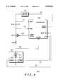
- FIG. 1shows a block diagram of a battery charger with active feedback voltage controller according to a preferred embodiment.
- FIG. 2shows a battery charger with active feedback voltage controller according to a first preferred embodiment
- FIG. 3shows a battery charger with active feedback voltage controller according to a second preferred embodiment.
- FIG. 4shows a battery charger with active feedback voltage controller according to a third preferred embodiment.
- a battery charger with active feedback voltage controllerincludes a pass device, such as a metal-oxide-semiconductor field-effect transistor (MOSFET), and implements an active feedback voltage controller to control a tracking regulator voltage supply and reduce power dissipation in the pass device.
- a pass devicesuch as a metal-oxide-semiconductor field-effect transistor (MOSFET)
- MOSFETmetal-oxide-semiconductor field-effect transistor
- an active feedback voltage controlleruses a fraction of the actual battery voltage, yet maintains the charging current required by a current controller. The fraction varies depending on the desired charging current as determined by the current controller, and other factors, such as the ambient temperature sensed by a battery thermistor, the actual battery voltage, or the battery type.
- a gate control line for a MOSFET pass deviceis connected to a BJT in the active feedback voltage controller to reduce the control voltage to the tracking regulator.
- a microprocessordirectly controls the tracking regulator depending on the desired charging current and other factors, such as the actual battery voltage, the calculated present charging current, or the ambient temperature sensed by a battery pack thermistor.
- the active feedback voltage controllermay include hardware, software, or a combination of hardware and software.
- the active feedback voltage controllerreduces the control voltage to the tracking regulator which in turn reduces the power dissipation of the pass device, and it allows for a smaller pass device to be implemented in the battery charger while maintaining the desired charging current as determined by the current controller.
- many types of batteriescan be efficiently charged to capacity, including nickel-cadmium (NiCad), nickel-metal-hydride (NiMH), and lithium-ion (LiIon) batteries, while reducing power dissipation.
- FIG. 1shows a block diagram of a battery charger 100 with active feedback voltage controller 130 according to a preferred embodiment.
- a tracking regulator 110provides a supply voltage that is a constant DC offset from a control voltage on a voltage control feedback line 135.
- the current controller 120establishes a current control value based on the present charging current and stored charging rates from either a memory in the current controller itself or from a data storage device 153, such as an EPROM, associated with a battery pack 150.
- a data line 121can send the current controller 120 additional information on data line 121, such as the battery type and the battery charging table, from a data storage device, such as an EPROM 153, usually found in a battery pack 150.
- the current controller 120can also receive ambient temperature information on temperature line 123 from a thermistor 156, which is built into most battery packs.
- the current control value determined from the present charging current, stored charging rates, and data and temperature information as available,is used to control the pass device 144, which charges battery cells 151 in the battery pack 150 through a diode 146.
- the current control valueis expressed as a voltage on the current control line 126.
- An active feedback voltage controller 130also receives the current control value from current control line 126 as well as the actual battery voltage on battery line 128. Using this information, the active feedback voltage controller 130 determines a voltage control value and expresses that value as a voltage on a voltage control feedback line 135 to the tracking regulator 110. The tracking regulator produces an output voltage that is a constant positive offset from the voltage on the voltage control feedback line 135. The active feedback voltage controller 130 is designed to provide the minimum voltage on the voltage control feedback line 135 needed to obtain the charging current specified by the current controller 120. By using the minimum voltage on the voltage control feedback line 135, the power dissipation of the battery charger 100, and especially the pass device 144, can be reduced. This reduces the thermal dissipation of the battery charger and may allow the package of the pass device 144 to be physically smaller.
- FIG. 2shows a battery charger 200 with active feedback voltage controller 230 according to a first preferred embodiment.
- the active feedback voltage controller 230is implemented using hardware components, namely a PNP bipolar junction transistor (BJT) 234 and two resistors 232, 236.
- the two resistors 232, 236compensate for manufacturer variations in the input impedance of the tracking regulator 210.
- the current controller 120 shown in FIG. 1is implemented using a microprocessor 220 which calculates the present charging current from a voltage on a supply line 222, a voltage on a sense line 224, and a known value of a sense resistor 242.
- the microprocessor 220determines the desired current control value and uses a current control line 226 to vary the voltage at the gate of the MOSFET pass device 244 to charge battery cells 251 in a battery pack 250 through a diode 246.
- the calculation of the current control valuecan include variables for ambient temperature as determined by a thermistor 256 and transmitted by temperature line 223 to the microprocessor 220 and battery type and battery charging table information from an EPROM or other type of data storage device 253 sent through data line 221.
- the current control line 226is also connected to the base of the BJT 234 through a resistor 232.
- the value of the resistor 232is selected to optimize the entire battery charger 200.
- the emitter of the BJT 234is connected to the battery pack 250 using battery line 228, and the collector of the BJT 234 is connected to the tracking regulator 210 using voltage control feedback line 235. As the voltage on the current control line 226 increases, the BJT 234 decreases the voltage on the voltage control feedback line 235 relative to the actual battery voltage on battery line 228.
- the BJT 234allows the voltage on the voltage control feedback line 235 to increase.
- This control systemshould settle down to a steady state that achieves the required charging current as calculated using sense resistor 242 and minimizes the power dissipation of the MOSFET pass device 244.
- the MOSFET pass device 244is generally driven at saturation to decrease power dissipation, and the BJT 234 is generally driven in linear mode or at saturation.
- the battery charger 200may oscillate due to the fact that the current controller implemented by the microprocessor 220 and the active feedback voltage controller 230 have different response times. This oscillation can be remedied using a delay circuit to slow the response time of the faster control loop, which in this case is the active feedback voltage controller 230.
- this delay circuitcould be implemented using the thermistor 256 and a variable capacitor.
- FIG. 3shows a battery charger 300 with active feedback voltage controller according to a second preferred embodiment.
- the active feedback voltage controller 330is also implemented using hardware components, specifically an NPN BJT 334 is used in a linear mode to create a variable resistor.
- the current controller 120 shown in FIG. 1is implemented using a microprocessor 320 which calculates the present charging current from a voltage on a supply line 322, a voltage on a sense line 324, and a known value of a sense resistor 342. The microprocessor 320 then determines the desired current control value and uses a current control line 326 to vary the voltage at the gate of the MOSFET 344 pass device to charge battery cells 351 in a battery pack 350 through a diode 346.
- the calculation of the current control valuecan include variables for ambient temperature as determined by a thermistor 356 and transmitted by temperature line 323 to the microprocessor 320 and battery type and battery charging table information from a data storage device 353 as sent through data line 321.
- the current control line 326is also connected to the base of the BJT 334 through a resistor 332.
- the value of the resistor 332is selected to optimize the entire battery charger 300.
- the emitter of the BJT 334is connected to ground, and the collector of the BJT 334 is connected to the battery pack 350 through battery line 328 and the tracking regulator 310 through voltage control feedback line 335.
- the charger MOSFET pass device 344is mostly off, and it is desirable to lower the voltage on the voltage control feedback line 335 relative to the actual battery voltage on the battery line 328.
- the BJT 334will begin to turn off. An equilibrium will eventually be reached between the MOSFET pass device 344 and the BJT 334, and thus the power dissipation can be minimized. Note that this approach, however, cannot adapt to major manufacturer variances in the tracking regulator 210 input impedance.
- the battery charger 300may oscillate due to the fact that the current controller implemented by the microprocessor 320 and the active feedback voltage controller 330 have different response times. This oscillation can be remedied using a delay circuit to slow the response time of the faster control loop, which in this case is the active feedback voltage controller 330.
- this delay circuitcould be implemented using the thermistor 356 and a variable capacitor.
- FIG. 4shows a battery charger 400 with active feedback voltage controller according to a third preferred embodiment.
- both the charger controller and the active feedback voltage controllerare implemented in a microprocessor 420.
- the microprocessor 420calculates the present charging current from a voltage on a supply line 422, a voltage on a sense line 424, and a known value of a sense resistor 442.
- the microprocessor 420determines the desired current control value and uses a current control line 426 to vary the voltage at the gate of the MOSFET pass device 444 to charge the battery cells 451 in a battery pack 450 through a diode 446.
- the current control valuecan also depend upon information from a thermistor 456 in the battery pack 450 as conveyed through a temperature line 423 or information from a data storage device 453, such as an EPROM, sent through data line 421.
- the microprocessor 420also receives an actual battery voltage on battery line 428 and determines the proper voltage to put on voltage control feedback line 435 going to the tracking regulator 410. This voltage is preferably determined using a mathematical formula; however, a table or particular parameters can be used to set the voltage on voltage control feedback line 435. A simple algorithm would stepwise increase the voltage on the voltage control feedback line 435 if the present charging current is less than the desired current control value, stepwise decrease the voltage on the voltage control feedback line 435 if the present charging current is greater than the current control value, and also stepwise decrease the voltage on the voltage control line if the present charging current is approximately equal to the current control value.
- a battery charger with active feedback voltage controlleractively reduces the feedback voltage to a tracking regulator, which in turn reduces power dissipation in a pass device. While specific components and functions of the battery charger with active feedback voltage controller are described above, fewer or additional functions could be employed by one skilled in the art within the true spirit and scope of the present invention. The invention should be limited only by the appended claims.
Landscapes
- Engineering & Computer Science (AREA)
- Power Engineering (AREA)
- Charge And Discharge Circuits For Batteries Or The Like (AREA)
- Secondary Cells (AREA)
Abstract
Description
This invention relates generally to battery chargers, and more particularly to limiting power dissipation in battery chargers that use a pass device.
Portable electronic devices, such as radiotelephones, currently use batteries as their main power source. Adapters, such as hands-free adapters, mobile transceiver adapters, cigarette lighter adapters, or wall charger adapters, can be connected to a vehicle cigarette lighter or an electrical outlet to provide an external power source for charging a battery attached to the portable electronic device. Many of these portable electronic devices use internal battery chargers to decrease the size of the adapters and increase convenience to the user.
In one type of internal battery charger, called a series pass charger, a linear switch pass device such as a metal-oxide-semiconductor field-effect transistor (MOSFET) is connected between a regulator and the battery. When a battery is charging, the power dissipated by the pass device is equal to the difference between the input and output voltages of the pass device multiplied by the maximum charging current. When a battery is deeply discharged, the battery voltage, which is the voltage at the output of the pass device, is much less than the regulator voltage, which is the voltage at the input of the pass device. During this condition, the power dissipated by the pass device could exceed maximum power ratings of typical device packages found in portable electronic devices. During a period of high power dissipation by the pass device, excess heat is generated and the overall efficiency of the battery charger is very poor.
Some internal battery chargers use an external tracking regulator physically located in the adapter to limit power dissipation in the charger's pass device. The tracking regulator provides a voltage that is a constant positive offset from the voltage of the battery being charged, thus holding the difference between the input and output voltages of the pass device relatively constant. When charging the battery, a microprocessor creates a control voltage proportional to a desired charging current, which controls the pass device (e.g., the gate of the MOSFET). The actual charging current is measured by a feedback loop that senses a voltage drop across a sense resistor, scales it, and compares it to the control voltage.
Even the use of an external tracking regulator, however, does not sufficiently reduce the power dissipation of an internal battery charger under certain conditions. For example, when the internal battery charger is implemented in a very small radiotelephone, the package of the pass device may be too small to properly dissipate the heat created by the pass device. Using a larger pass device package would make heat dissipation more efficient, but the drawback is that a larger package would make it difficult to fit the internal battery charger into the very small radiotelephone. Thus, it would be advantageous to further limit power dissipation in the internal battery charger to allow a reduction in the size of the pass device.
FIG. 1 shows a block diagram of a battery charger with active feedback voltage controller according to a preferred embodiment.
FIG. 2 shows a battery charger with active feedback voltage controller according to a first preferred embodiment,
FIG. 3 shows a battery charger with active feedback voltage controller according to a second preferred embodiment.
FIG. 4 shows a battery charger with active feedback voltage controller according to a third preferred embodiment.
A battery charger with active feedback voltage controller includes a pass device, such as a metal-oxide-semiconductor field-effect transistor (MOSFET), and implements an active feedback voltage controller to control a tracking regulator voltage supply and reduce power dissipation in the pass device. Instead of using an actual battery voltage to control the tracking regulator directly, an active feedback voltage controller uses a fraction of the actual battery voltage, yet maintains the charging current required by a current controller. The fraction varies depending on the desired charging current as determined by the current controller, and other factors, such as the ambient temperature sensed by a battery thermistor, the actual battery voltage, or the battery type. In two embodiments of the active feedback voltage controller, a gate control line for a MOSFET pass device is connected to a BJT in the active feedback voltage controller to reduce the control voltage to the tracking regulator. In another embodiment of the active feedback voltage controller, a microprocessor directly controls the tracking regulator depending on the desired charging current and other factors, such as the actual battery voltage, the calculated present charging current, or the ambient temperature sensed by a battery pack thermistor.
The active feedback voltage controller may include hardware, software, or a combination of hardware and software. The active feedback voltage controller reduces the control voltage to the tracking regulator which in turn reduces the power dissipation of the pass device, and it allows for a smaller pass device to be implemented in the battery charger while maintaining the desired charging current as determined by the current controller. With software flexibility, many types of batteries can be efficiently charged to capacity, including nickel-cadmium (NiCad), nickel-metal-hydride (NiMH), and lithium-ion (LiIon) batteries, while reducing power dissipation.
FIG. 1 shows a block diagram of a battery charger 100 with active feedback voltage controller 130 according to a preferred embodiment. A tracking regulator 110 provides a supply voltage that is a constant DC offset from a control voltage on a voltage control feedback line 135. A current controller 120 calculates a present charging current to a battery pack 150 using a voltage at a supply line 122 and a voltage at a sense line 124 on either side of a sense resistor 142 (I=(Vsupply -Vsense)/Rsense). There are various alternate methods of determining the present charging current, including placing the sense resistor could be placed in another location.
After the present charging current is determined, the current controller 120 establishes a current control value based on the present charging current and stored charging rates from either a memory in the current controller itself or from a data storage device 153, such as an EPROM, associated with a battery pack 150. A data line 121 can send the current controller 120 additional information on data line 121, such as the battery type and the battery charging table, from a data storage device, such as an EPROM 153, usually found in a battery pack 150. The current controller 120 can also receive ambient temperature information on temperature line 123 from a thermistor 156, which is built into most battery packs. The current control value determined from the present charging current, stored charging rates, and data and temperature information as available, is used to control the pass device 144, which charges battery cells 151 in the battery pack 150 through a diode 146. In this implementation, the current control value is expressed as a voltage on the current control line 126.
An active feedback voltage controller 130 also receives the current control value from current control line 126 as well as the actual battery voltage on battery line 128. Using this information, the active feedback voltage controller 130 determines a voltage control value and expresses that value as a voltage on a voltage control feedback line 135 to the tracking regulator 110. The tracking regulator produces an output voltage that is a constant positive offset from the voltage on the voltage control feedback line 135. The active feedback voltage controller 130 is designed to provide the minimum voltage on the voltage control feedback line 135 needed to obtain the charging current specified by the current controller 120. By using the minimum voltage on the voltage control feedback line 135, the power dissipation of the battery charger 100, and especially the pass device 144, can be reduced. This reduces the thermal dissipation of the battery charger and may allow the package of the pass device 144 to be physically smaller.
FIG. 2 shows a battery charger 200 with active feedback voltage controller 230 according to a first preferred embodiment. In this embodiment, the active feedback voltage controller 230 is implemented using hardware components, namely a PNP bipolar junction transistor (BJT) 234 and two resistors 232, 236. The two resistors 232, 236 compensate for manufacturer variations in the input impedance of the tracking regulator 210. The current controller 120 shown in FIG. 1 is implemented using a microprocessor 220 which calculates the present charging current from a voltage on a supply line 222, a voltage on a sense line 224, and a known value of a sense resistor 242. The microprocessor 220 then determines the desired current control value and uses a current control line 226 to vary the voltage at the gate of the MOSFET pass device 244 to charge battery cells 251 in a battery pack 250 through a diode 246.
The calculation of the current control value can include variables for ambient temperature as determined by a thermistor 256 and transmitted by temperature line 223 to the microprocessor 220 and battery type and battery charging table information from an EPROM or other type of data storage device 253 sent through data line 221.
The current control line 226 is also connected to the base of the BJT 234 through a resistor 232. The value of the resistor 232 is selected to optimize the entire battery charger 200. The emitter of the BJT 234 is connected to the battery pack 250 using battery line 228, and the collector of the BJT 234 is connected to the tracking regulator 210 using voltage control feedback line 235. As the voltage on the current control line 226 increases, the BJT 234 decreases the voltage on the voltage control feedback line 235 relative to the actual battery voltage on battery line 228. When the voltage on the voltage control feedback line 235 is so low as to cause the microprocessor 220 to increase the voltage on the current control line (due to a change in the present charging current), the BJT 234 allows the voltage on the voltage control feedback line 235 to increase. This control system should settle down to a steady state that achieves the required charging current as calculated using sense resistor 242 and minimizes the power dissipation of the MOSFET pass device 244. During equilibrium, the MOSFET pass device 244 is generally driven at saturation to decrease power dissipation, and the BJT 234 is generally driven in linear mode or at saturation.
Under certain circumstances, the battery charger 200 may oscillate due to the fact that the current controller implemented by the microprocessor 220 and the active feedback voltage controller 230 have different response times. This oscillation can be remedied using a delay circuit to slow the response time of the faster control loop, which in this case is the active feedback voltage controller 230. For a LiIon battery charger, this delay circuit could be implemented using the thermistor 256 and a variable capacitor.
FIG. 3 shows a battery charger 300 with active feedback voltage controller according to a second preferred embodiment. The active feedback voltage controller 330 is also implemented using hardware components, specifically an NPN BJT 334 is used in a linear mode to create a variable resistor. The current controller 120 shown in FIG. 1 is implemented using a microprocessor 320 which calculates the present charging current from a voltage on a supply line 322, a voltage on a sense line 324, and a known value of a sense resistor 342. The microprocessor 320 then determines the desired current control value and uses a current control line 326 to vary the voltage at the gate of the MOSFET 344 pass device to charge battery cells 351 in a battery pack 350 through a diode 346.
The calculation of the current control value can include variables for ambient temperature as determined by a thermistor 356 and transmitted by temperature line 323 to the microprocessor 320 and battery type and battery charging table information from a data storage device 353 as sent through data line 321.
The current control line 326 is also connected to the base of the BJT 334 through a resistor 332. The value of the resistor 332 is selected to optimize the entire battery charger 300. The emitter of the BJT 334 is connected to ground, and the collector of the BJT 334 is connected to the battery pack 350 through battery line 328 and the tracking regulator 310 through voltage control feedback line 335. When the voltage on the current control line 326 is high, the charger MOSFET pass device 344 is mostly off, and it is desirable to lower the voltage on the voltage control feedback line 335 relative to the actual battery voltage on the battery line 328. As the voltage on the voltage control feedback line 335 is lowered, the BJT 334 will begin to turn off. An equilibrium will eventually be reached between the MOSFET pass device 344 and the BJT 334, and thus the power dissipation can be minimized. Note that this approach, however, cannot adapt to major manufacturer variances in the tracking regulator 210 input impedance.
Under certain circumstances, the battery charger 300 may oscillate due to the fact that the current controller implemented by the microprocessor 320 and the active feedback voltage controller 330 have different response times. This oscillation can be remedied using a delay circuit to slow the response time of the faster control loop, which in this case is the active feedback voltage controller 330. For a LiIon battery charger, this delay circuit could be implemented using the thermistor 356 and a variable capacitor.
FIG. 4 shows abattery charger 400 with active feedback voltage controller according to a third preferred embodiment. In this approach, both the charger controller and the active feedback voltage controller are implemented in amicroprocessor 420. This eliminates the potential for oscillation, because themicroprocessor 420 directly controls both the voltage on thecurrent control line 426 and the voltage on the voltagecontrol feedback line 435. Themicroprocessor 420 calculates the present charging current from a voltage on asupply line 422, a voltage on asense line 424, and a known value of asense resistor 442. Themicroprocessor 420 then determines the desired current control value and uses acurrent control line 426 to vary the voltage at the gate of theMOSFET pass device 444 to charge thebattery cells 451 in abattery pack 450 through adiode 446. The current control value can also depend upon information from athermistor 456 in thebattery pack 450 as conveyed through atemperature line 423 or information from adata storage device 453, such as an EPROM, sent throughdata line 421.
Themicroprocessor 420 also receives an actual battery voltage onbattery line 428 and determines the proper voltage to put on voltagecontrol feedback line 435 going to thetracking regulator 410. This voltage is preferably determined using a mathematical formula; however, a table or particular parameters can be used to set the voltage on voltagecontrol feedback line 435. A simple algorithm would stepwise increase the voltage on the voltagecontrol feedback line 435 if the present charging current is less than the desired current control value, stepwise decrease the voltage on the voltagecontrol feedback line 435 if the present charging current is greater than the current control value, and also stepwise decrease the voltage on the voltage control line if the present charging current is approximately equal to the current control value.
Thus, a battery charger with active feedback voltage controller actively reduces the feedback voltage to a tracking regulator, which in turn reduces power dissipation in a pass device. While specific components and functions of the battery charger with active feedback voltage controller are described above, fewer or additional functions could be employed by one skilled in the art within the true spirit and scope of the present invention. The invention should be limited only by the appended claims.
Claims (14)
1. A battery charger with active feedback voltage controller comprising:
a pass device configured for connection between a tracking regulator and a battery pack;
a current controller, coupled to the pass device, for determining a present charging current going to the battery pack and determining a current control value for controlling the pass device based on the present charging current; and
an active feedback voltage controller, coupled to the current controller and configured for connection to the tracking regulator and the battery pack, for receiving the current control value and an actual battery voltage and determining a voltage control value to control an output voltage of the tracking regulator based on the current control value and an actual battery voltage.
2. A battery charger according to claim 1 wherein the active feedback voltage controller comprises:
a hardware feedback loop.
3. A battery charger according to claim 2 wherein the active feedback voltage controller further comprises:
an PNP bipolar junction transistor.
4. A battery charger according to claim 3 wherein a base of the PNP bipolar junction transistor is coupled to receive a voltage representing the current control value, an emitter of the PNP bipolar junction transistor is coupled to the battery pack, and a collector of the PNP bipolar junction transistor is coupled to the tracking regulator.
5. A battery charger according to claim 2 wherein the active feedback voltage controller further comprises:
an NPN bipolar junction transistor.
6. A battery charger according to claim 5 wherein a base of the NPN bipolar junction transistor is coupled to receive a voltage representing the current control value, an emitter of the NPN bipolar junction transistor is coupled to ground, and a collector of the NPN bipolar junction transistor is coupled to the battery pack and the tracking regulator.
7. A battery charger according to claim 1 wherein the active feedback voltage controller comprises:
a software feedback loop.
8. A battery charger according to claim 1 wherein the current controller comprises:
a temperature sense input configured for connection to a thermistor.
9. A battery charger according to claim 1 wherein the current controller comprises:
a data input configured for connection to a data storage device.
10. A battery charger with active feedback voltage controller comprising:
a pass device having an input configured for connection to a tracking regulator and an output configured for connection to a battery pack; and
a controller, coupled to the pass device, having:
a means for determining a present charging current going to the battery pack and determining a current control value;
a current control line, coupled to a gate of the pass device, for using the current control value to control the pass device;
a battery line, coupled to the battery pack, for sensing an actual battery voltage; and
a voltage control feedback line, configured for connection to the battery pack and the tracking regulator, for controlling an output voltage of the tracking regulator based on the current control value and the actual battery voltage.
11. A battery charger with active feedback voltage controller according to claim 10 further comprising:
a sense resistor having a resistance value, coupled between the tracking regulator and the pass device, wherein the means for determining a present charging current calculates the present charging current by dividing a voltage drop across the sense resistor by the resistance value.
12. A battery charger with active feedback voltage controller according to claim 10 wherein the controller further comprises:
a temperature sense input for connection to a thermistor.
13. A battery charger with active feedback voltage controller according to claim 10 wherein the controller further comprises:
a data input for connection to a data storage device.
14. A method for charging a battery comprising the steps of:
coupling a tracking regulator to a pass device;
coupling the pass device to the battery;
determining a present charging current going to the battery;
computing a current control value;
sensing an actual battery voltage of the battery;
increasing a voltage on a voltage control feedback line relative to the actual battery voltage when the present charging current is less than the current control value;
decreasing a voltage on the voltage control feedback line relative to the actual battery voltage when the present charging current is greater than the current control value; and
decreasing a voltage on the voltage control feedback line relative to the actual battery voltage when the present charging current is approximately equal to the current control value.
Priority Applications (1)
| Application Number | Priority Date | Filing Date | Title |
|---|---|---|---|
| US09/322,093US6040683A (en) | 1999-05-28 | 1999-05-28 | Battery charger with active feedback voltage controller |
Applications Claiming Priority (1)
| Application Number | Priority Date | Filing Date | Title |
|---|---|---|---|
| US09/322,093US6040683A (en) | 1999-05-28 | 1999-05-28 | Battery charger with active feedback voltage controller |
Publications (1)
| Publication Number | Publication Date |
|---|---|
| US6040683Atrue US6040683A (en) | 2000-03-21 |
Family
ID=23253379
Family Applications (1)
| Application Number | Title | Priority Date | Filing Date |
|---|---|---|---|
| US09/322,093Expired - LifetimeUS6040683A (en) | 1999-05-28 | 1999-05-28 | Battery charger with active feedback voltage controller |
Country Status (1)
| Country | Link |
|---|---|
| US (1) | US6040683A (en) |
Cited By (25)
| Publication number | Priority date | Publication date | Assignee | Title |
|---|---|---|---|---|
| US6191556B1 (en)* | 1999-10-12 | 2001-02-20 | International Business Machines Corporation | Method and apparatus for estimating the service life of a battery |
| US6291973B1 (en)* | 1999-02-01 | 2001-09-18 | Mitac International Corp. | External discharging/charging apparatus |
| EP1217710A1 (en)* | 2000-12-21 | 2002-06-26 | Makita Corporation | Charging system and battery pack |
| US6697645B1 (en)* | 2000-08-17 | 2004-02-24 | Motorola, Inc. | Phone with ambient temperature sensor and display |
| US20040124810A1 (en)* | 2002-12-30 | 2004-07-01 | Smallwood Ralph D. | Method for charging a battery |
| EP1263112A3 (en)* | 2001-05-31 | 2004-08-11 | Matsushita Communication Industrial UK Ltd. | Charging circuits for portable communication terminals |
| US20040257038A1 (en)* | 2002-11-22 | 2004-12-23 | Johnson Todd W. | Battery pack |
| US20040263119A1 (en)* | 2002-11-22 | 2004-12-30 | Meyer Gary D. | Method and system for battery charging |
| US20050007068A1 (en)* | 2002-11-22 | 2005-01-13 | Johnson Todd W. | Method and system for battery protection |
| US20060071634A1 (en)* | 2002-11-22 | 2006-04-06 | Meyer Gary D | Method and system for battery charging |
| US20060091858A1 (en)* | 2002-11-22 | 2006-05-04 | Johnson Todd W | Method and system for battery protection |
| US20060164032A1 (en)* | 2002-11-22 | 2006-07-27 | Johnson Todd W | Battery pack |
| US20060204795A1 (en)* | 2005-03-14 | 2006-09-14 | Alfred E. Mann Foundation For Scientific Research | Energy storage device charging system |
| US20070173090A1 (en)* | 2006-01-10 | 2007-07-26 | Johnson Todd W | Battery pack |
| US20070285055A1 (en)* | 2006-06-07 | 2007-12-13 | Meyer Gary D | Battery pack |
| USD558670S1 (en) | 2006-01-09 | 2008-01-01 | Milwaukee Electric Tool Corporation | Battery |
| US20100225275A1 (en)* | 2008-09-05 | 2010-09-09 | Constantin Bucur | Cell balancing systems employing transformers |
| US20100244784A1 (en)* | 2008-10-09 | 2010-09-30 | Guoxing Li | Battery charging systems |
| US20110215767A1 (en)* | 2002-11-22 | 2011-09-08 | Johnson Todd W | Battery pack |
| US20110215769A1 (en)* | 2010-03-08 | 2011-09-08 | Hon Hai Precision Industry Co., Ltd. | Battery charging system and method |
| US9077052B2 (en) | 2012-09-06 | 2015-07-07 | General Electric Company | Methods and systems for charging an energy storage device |
| US9166423B2 (en) | 2012-01-24 | 2015-10-20 | Google Inc. | Battery leakage current elimination in UPS units |
| US10361577B2 (en) | 2016-04-05 | 2019-07-23 | Adam Gleason | Battery charging and cooling apparatus |
| US10714956B2 (en) | 2016-04-05 | 2020-07-14 | Adam Gleason | Apparatus, system, and method for battery charging |
| US20220311259A1 (en)* | 2021-03-26 | 2022-09-29 | Rohm Co., Ltd. | Charging circuit |
Citations (7)
| Publication number | Priority date | Publication date | Assignee | Title |
|---|---|---|---|---|
| US5130634A (en)* | 1989-07-05 | 1992-07-14 | Nec Corporation | Battery charger for a portable wireless telephone set having means for tricklingly charging the battery with an increased current during a stand-by period of the telephone set |
| US5481174A (en)* | 1993-12-27 | 1996-01-02 | Motorola, Inc. | Method of rapidly charging a lithium ion cell |
| US5498950A (en)* | 1994-04-29 | 1996-03-12 | Delco Electronics Corp. | Battery monitoring, charging and balancing apparatus |
| US5587649A (en)* | 1994-09-30 | 1996-12-24 | Motorola, Inc. | Thermal performance matched current limiting circuit, and battery using same |
| US5691620A (en)* | 1993-09-17 | 1997-11-25 | Sony Corporation | Battery charging method |
| US5703470A (en)* | 1996-05-29 | 1997-12-30 | Motorola, Inc. | Battery charger with power dissipation control |
| US5818199A (en)* | 1995-11-20 | 1998-10-06 | Norand Corporation | Current limited charging apparatus for lithium batteries or the like |
- 1999
- 1999-05-28USUS09/322,093patent/US6040683A/ennot_activeExpired - Lifetime
Patent Citations (7)
| Publication number | Priority date | Publication date | Assignee | Title |
|---|---|---|---|---|
| US5130634A (en)* | 1989-07-05 | 1992-07-14 | Nec Corporation | Battery charger for a portable wireless telephone set having means for tricklingly charging the battery with an increased current during a stand-by period of the telephone set |
| US5691620A (en)* | 1993-09-17 | 1997-11-25 | Sony Corporation | Battery charging method |
| US5481174A (en)* | 1993-12-27 | 1996-01-02 | Motorola, Inc. | Method of rapidly charging a lithium ion cell |
| US5498950A (en)* | 1994-04-29 | 1996-03-12 | Delco Electronics Corp. | Battery monitoring, charging and balancing apparatus |
| US5587649A (en)* | 1994-09-30 | 1996-12-24 | Motorola, Inc. | Thermal performance matched current limiting circuit, and battery using same |
| US5818199A (en)* | 1995-11-20 | 1998-10-06 | Norand Corporation | Current limited charging apparatus for lithium batteries or the like |
| US5703470A (en)* | 1996-05-29 | 1997-12-30 | Motorola, Inc. | Battery charger with power dissipation control |
Cited By (120)
| Publication number | Priority date | Publication date | Assignee | Title |
|---|---|---|---|---|
| US6291973B1 (en)* | 1999-02-01 | 2001-09-18 | Mitac International Corp. | External discharging/charging apparatus |
| US6271647B2 (en) | 1999-10-12 | 2001-08-07 | International Business Machines Corporation | Method and apparatus for estimating the service life of a battery |
| US6191556B1 (en)* | 1999-10-12 | 2001-02-20 | International Business Machines Corporation | Method and apparatus for estimating the service life of a battery |
| US6563290B2 (en) | 2000-02-21 | 2003-05-13 | Makita Corporation | Battery pack charging system and battery pack |
| US6697645B1 (en)* | 2000-08-17 | 2004-02-24 | Motorola, Inc. | Phone with ambient temperature sensor and display |
| EP1837975A2 (en)* | 2000-12-21 | 2007-09-26 | Makita Corporation | Charging System and Battery Pack |
| EP1217710A1 (en)* | 2000-12-21 | 2002-06-26 | Makita Corporation | Charging system and battery pack |
| EP1837974A3 (en)* | 2000-12-21 | 2007-12-12 | Makita Corporation | Charging System and Battery Pack |
| EP1263112A3 (en)* | 2001-05-31 | 2004-08-11 | Matsushita Communication Industrial UK Ltd. | Charging circuits for portable communication terminals |
| US7944181B2 (en) | 2002-11-22 | 2011-05-17 | Milwaukee Electric Tool Corporation | Battery pack |
| US9673648B2 (en) | 2002-11-22 | 2017-06-06 | Milwaukee Electric Tool Corporation | Lithium-based battery pack for a hand held power tool |
| US11837694B2 (en) | 2002-11-22 | 2023-12-05 | Milwaukee Electric Tool Corporation | Lithium-based battery pack |
| US20050258801A9 (en)* | 2002-11-22 | 2005-11-24 | Johnson Todd W | Method and system for battery protection |
| US20060071634A1 (en)* | 2002-11-22 | 2006-04-06 | Meyer Gary D | Method and system for battery charging |
| US20060091858A1 (en)* | 2002-11-22 | 2006-05-04 | Johnson Todd W | Method and system for battery protection |
| US20060103357A1 (en)* | 2002-11-22 | 2006-05-18 | Johnson Todd W | Method and system for battery protection |
| US20060108984A1 (en)* | 2002-11-22 | 2006-05-25 | Johnson Todd W | Method and system for battery protection |
| US20060108975A1 (en)* | 2002-11-22 | 2006-05-25 | Milwaukee Electric Tool Corporation | Method and system for battery charging |
| US20060108983A1 (en)* | 2002-11-22 | 2006-05-25 | Milwaukee Electric Tool Corporation. | Method and system for battery charging |
| US20060164032A1 (en)* | 2002-11-22 | 2006-07-27 | Johnson Todd W | Battery pack |
| US11682910B2 (en) | 2002-11-22 | 2023-06-20 | Milwaukee Electric Tool Corporation | Method of operating a lithium-based battery pack for a hand held power tool |
| US11469608B2 (en) | 2002-11-22 | 2022-10-11 | Milwaukee Electric Tool Corporation | Lithium-based battery pack for a hand held power tool |
| US7157882B2 (en) | 2002-11-22 | 2007-01-02 | Milwaukee Electric Tool Corporation | Method and system for battery protection employing a selectively-actuated switch |
| US7157883B2 (en) | 2002-11-22 | 2007-01-02 | Milwaukee Electric Tool Corporation | Method and system for battery protection employing averaging of measurements |
| US7164257B2 (en) | 2002-11-22 | 2007-01-16 | Milwaukee Electric Tool Corporation | Method and system for protection of a lithium-based multicell battery pack including a heat sink |
| US7176654B2 (en) | 2002-11-22 | 2007-02-13 | Milwaukee Electric Tool Corporation | Method and system of charging multi-cell lithium-based batteries |
| US20070103116A1 (en)* | 2002-11-22 | 2007-05-10 | Johnson Todd W | Method and system for battery protection employing sampling of measurements |
| US20070103121A1 (en)* | 2002-11-22 | 2007-05-10 | Johnson Todd W | Method and system for battery protection |
| US20070103109A1 (en)* | 2002-11-22 | 2007-05-10 | Meyer Gary D | Method and system of charging multi-cell lithium-based batteries |
| US11196080B2 (en) | 2002-11-22 | 2021-12-07 | Milwaukee Electric Tool Corporation | Method and system for battery protection |
| US7253585B2 (en) | 2002-11-22 | 2007-08-07 | Milwaukee Electric Tool Corporation | Battery pack |
| US7262580B2 (en) | 2002-11-22 | 2007-08-28 | Milwaukee Electric Tool Corporation | Method and system for charging multi-cell lithium-based batteries |
| US20040263119A1 (en)* | 2002-11-22 | 2004-12-30 | Meyer Gary D. | Method and system for battery charging |
| US11063446B2 (en) | 2002-11-22 | 2021-07-13 | Milwaukee Electric Tool Corporation | Method and system for charging multi-cell lithium-based battery packs |
| US20070273334A1 (en)* | 2002-11-22 | 2007-11-29 | Meyer Gary D | Method and system for charging multi-cell lithium-based batteries |
| US20040257038A1 (en)* | 2002-11-22 | 2004-12-23 | Johnson Todd W. | Battery pack |
| US10998586B2 (en) | 2002-11-22 | 2021-05-04 | Milwaukee Electric Tool Corporation | Lithium-based battery pack including a balancing circuit |
| US10886762B2 (en) | 2002-11-22 | 2021-01-05 | Milwaukee Electric Tool Corporation | Lithium-based battery pack for a hand held power tool |
| US20080012530A1 (en)* | 2002-11-22 | 2008-01-17 | Johnson Todd W | Battery pack |
| US7321219B2 (en) | 2002-11-22 | 2008-01-22 | Milwaukee Electric Tool Corporation | Method and system for battery charging employing a semiconductor switch |
| US20110214896A1 (en)* | 2002-11-22 | 2011-09-08 | Johnson Todd W | Lithium-based battery pack for a hand held power tool |
| US7342381B2 (en) | 2002-11-22 | 2008-03-11 | Milwaukee Electric Tool Corporation | Method and system for battery protection employing sampling of measurements |
| US20080185993A1 (en)* | 2002-11-22 | 2008-08-07 | Johnson Todd W | Battery pack |
| US7425816B2 (en) | 2002-11-22 | 2008-09-16 | Milwaukee Electric Tool Corporation | Method and system for pulse charging of a lithium-based battery |
| US7492124B2 (en) | 2002-11-22 | 2009-02-17 | Milwaukee Electric Tool Corporation | Method and system for battery protection |
| US7504804B2 (en) | 2002-11-22 | 2009-03-17 | Milwaukee Electric Tool Corporation | Method and system for protection of a lithium-based multicell battery pack including a heat sink |
| US7508167B2 (en) | 2002-11-22 | 2009-03-24 | Milwaukee Electric Tool Corporation | Method and system for charging multi-cell lithium-based batteries |
| US20090087729A1 (en)* | 2002-11-22 | 2009-04-02 | Johnson Todd W | Lithium-based battery pack for a hand held power tool |
| US20090153101A1 (en)* | 2002-11-22 | 2009-06-18 | Meyer Gary D | Method and system for charging multi-cell lithium-based batteries |
| US7554290B2 (en) | 2002-11-22 | 2009-06-30 | Milwaukee Electric Tool Corporation | Lithium-based battery pack for a hand-held power tool |
| US7557535B2 (en) | 2002-11-22 | 2009-07-07 | Milwaukee Electric Tool Corporation | Lithium-based battery for a hand held power tool |
| US20090195216A1 (en)* | 2002-11-22 | 2009-08-06 | Johnson Todd W | Method and system for protection of a lithium-based multicell battery pack including a heat sink |
| US20090197152A1 (en)* | 2002-11-22 | 2009-08-06 | Johnson Todd W | Method and system for battery protection |
| US7589500B2 (en) | 2002-11-22 | 2009-09-15 | Milwaukee Electric Tool Corporation | Method and system for battery protection |
| US7667437B2 (en) | 2002-11-22 | 2010-02-23 | Milwaukee Electric Tool Corporation | Method and system for protection of a lithium-based multicell battery pack including a heat sink |
| US7714538B2 (en) | 2002-11-22 | 2010-05-11 | Milwaukee Electric Tool Corporation | Battery pack |
| US10862327B2 (en) | 2002-11-22 | 2020-12-08 | Milwaukee Electric Tool Corporation | Lithium-based battery pack for a hand held power tool |
| US20100236807A1 (en)* | 2002-11-22 | 2010-09-23 | Johnson Todd W | Battery pack |
| US10714948B2 (en) | 2002-11-22 | 2020-07-14 | Milwaukee Electric Tool Corporation | Method and system for charging multi-cell lithium-based battery packs |
| US20100327815A1 (en)* | 2002-11-22 | 2010-12-30 | Johnson Todd W | Battery pack |
| US10593991B2 (en) | 2002-11-22 | 2020-03-17 | Milwaukee Electric Tool Corporation | Method and system for battery protection |
| US7944173B2 (en) | 2002-11-22 | 2011-05-17 | Milwaukee Electric Tool Corporation | Lithium-based battery pack for a high current draw, hand held power tool |
| US20110114350A1 (en)* | 2002-11-22 | 2011-05-19 | Johnson Todd W | Lithium-based battery pack for a hand held power tool |
| US20050007068A1 (en)* | 2002-11-22 | 2005-01-13 | Johnson Todd W. | Method and system for battery protection |
| US10141614B2 (en) | 2002-11-22 | 2018-11-27 | Milwaukee Electric Tool Corporation | Battery pack |
| US7323847B2 (en) | 2002-11-22 | 2008-01-29 | Milwaukee Electric Tool Corporation | Method and system of charging multi-cell lithium-based batteries |
| US20110215767A1 (en)* | 2002-11-22 | 2011-09-08 | Johnson Todd W | Battery pack |
| US10566810B2 (en) | 2002-11-22 | 2020-02-18 | Milwaukee Electric Tool Corporation | Lithium-based battery pack for a hand held power tool |
| US8018198B2 (en) | 2002-11-22 | 2011-09-13 | Milwaukee Electric Tool Corporation | Method and system for charging multi-cell lithium-based batteries |
| US8154249B2 (en) | 2002-11-22 | 2012-04-10 | Milwaukee Electric Tool Corporation | Battery pack |
| US8207702B2 (en) | 2002-11-22 | 2012-06-26 | Milwaukee Electric Tool Corporation | Lithium-based battery pack for a hand held power tool |
| US8269459B2 (en) | 2002-11-22 | 2012-09-18 | Milwaukee Electric Tool Corporation | Lithium-based battery pack for a high current draw, hand held power tool |
| US10536022B2 (en) | 2002-11-22 | 2020-01-14 | Milwaukee Electric Tool Corporation | Lithium-based battery pack for a hand held power tool |
| US10431857B2 (en) | 2002-11-22 | 2019-10-01 | Milwaukee Electric Tool Corporation | Lithium-based battery pack |
| US8450971B2 (en) | 2002-11-22 | 2013-05-28 | Milwaukee Electric Tool Corporation | Lithium-based battery pack for a hand held power tool |
| US8471532B2 (en) | 2002-11-22 | 2013-06-25 | Milwaukee Electric Tool Corporation | Battery pack |
| US8487585B2 (en) | 2002-11-22 | 2013-07-16 | Milwaukee Electric Tool Corporation | Battery pack |
| US8525479B2 (en) | 2002-11-22 | 2013-09-03 | Milwaukee Electric Tool Corporation | Method and system for charging multi-cell lithium-based batteries |
| US8653790B2 (en) | 2002-11-22 | 2014-02-18 | Milwaukee Electric Tool Corporation | Battery pack |
| US8822067B2 (en) | 2002-11-22 | 2014-09-02 | Milwaukee Electric Tool Corporation | Battery Pack |
| US9018903B2 (en) | 2002-11-22 | 2015-04-28 | Milwaukee Electric Tool Corporation | Lithium-based battery pack for a hand held power tool |
| US9048515B2 (en) | 2002-11-22 | 2015-06-02 | Milwaukee Electric Tool Corporation | Battery pack |
| US10374443B2 (en) | 2002-11-22 | 2019-08-06 | Milwaukee Electric Tool Corporation | Method and system for charging multi-cell lithium-based battery packs |
| US9112248B2 (en) | 2002-11-22 | 2015-08-18 | Milwaukee Electric Tool Corporation | Method and system for battery protection |
| US9118189B2 (en) | 2002-11-22 | 2015-08-25 | Milwaukee Electric Tool Corporation | Method and system for charging multi-cell lithium-based battery packs |
| US10224566B2 (en) | 2002-11-22 | 2019-03-05 | Milwaukee Electric Tool Corporation | Method and system for battery protection |
| US10218194B2 (en) | 2002-11-22 | 2019-02-26 | Milwaukee Electric Tool Corporation | Lithium-based battery pack for a hand held power tool |
| US9312721B2 (en) | 2002-11-22 | 2016-04-12 | Milwaukee Electric Tool Corporation | Lithium-based battery pack for a hand held power tool |
| US9368842B2 (en) | 2002-11-22 | 2016-06-14 | Milwaukee Electric Tool Corporation | Battery pack |
| US9379569B2 (en) | 2002-11-22 | 2016-06-28 | Milwaukee Electric Tool Corporation | Lithium-battery pack for a hand held power tool |
| US9660293B2 (en) | 2002-11-22 | 2017-05-23 | Milwaukee Electric Tool Corporation | Method and system for battery protection |
| US7952326B2 (en) | 2002-11-22 | 2011-05-31 | Milwaukee Electric Tool Corporation | Method and system for battery protection employing over-discharge control |
| US9680325B2 (en) | 2002-11-22 | 2017-06-13 | Milwaukee Electric Tool Corporation | Lithium-based battery pack for a hand held power tool |
| US9793583B2 (en) | 2002-11-22 | 2017-10-17 | Milwaukee Electric Tool Corporation | Lithium-based battery pack |
| US9819051B2 (en) | 2002-11-22 | 2017-11-14 | Milwaukee Electric Tool Corporation | Method and system for battery protection |
| US7999510B2 (en) | 2002-11-22 | 2011-08-16 | Milwaukee Electric Tool Corporation | Lithium-based battery pack for a high current draw, hand held power tool |
| US9941718B2 (en) | 2002-11-22 | 2018-04-10 | Milwaukee Electric Tool Corporation | Lithium-based battery pack for a hand held power tool |
| US10008864B2 (en) | 2002-11-22 | 2018-06-26 | Milwaukee Electric Tool Corporation | Method and system for charging multi-cell lithium-based battery packs |
| US10097026B2 (en) | 2002-11-22 | 2018-10-09 | Milwaukee Electric Tool Corporation | Lithium-based battery pack for a hand held power tool |
| US20040124810A1 (en)* | 2002-12-30 | 2004-07-01 | Smallwood Ralph D. | Method for charging a battery |
| US20050017683A1 (en)* | 2002-12-30 | 2005-01-27 | Smallwood Ralph D. | Method for charging a battery |
| US7282891B2 (en) | 2002-12-30 | 2007-10-16 | Motorola, Inc. | Method for charging a battery |
| US20060204795A1 (en)* | 2005-03-14 | 2006-09-14 | Alfred E. Mann Foundation For Scientific Research | Energy storage device charging system |
| EP1703615A1 (en)* | 2005-03-14 | 2006-09-20 | Alfred E. Mann Foundation for Scientific Research | Energy storage device charging system |
| USD558670S1 (en) | 2006-01-09 | 2008-01-01 | Milwaukee Electric Tool Corporation | Battery |
| US20070173090A1 (en)* | 2006-01-10 | 2007-07-26 | Johnson Todd W | Battery pack |
| US20070285055A1 (en)* | 2006-06-07 | 2007-12-13 | Meyer Gary D | Battery pack |
| US8294421B2 (en) | 2008-09-05 | 2012-10-23 | O2Micro Inc | Cell balancing systems employing transformers |
| US20100225275A1 (en)* | 2008-09-05 | 2010-09-09 | Constantin Bucur | Cell balancing systems employing transformers |
| US8339108B2 (en)* | 2008-10-09 | 2012-12-25 | 02Micro Inc | Charging systems that control power dissipation in a charging path |
| US20100244784A1 (en)* | 2008-10-09 | 2010-09-30 | Guoxing Li | Battery charging systems |
| US20110215769A1 (en)* | 2010-03-08 | 2011-09-08 | Hon Hai Precision Industry Co., Ltd. | Battery charging system and method |
| US9843221B1 (en) | 2012-01-24 | 2017-12-12 | Google Llc | Redundant charging and discharging MOSFET driving in battery backup system |
| US9166423B2 (en) | 2012-01-24 | 2015-10-20 | Google Inc. | Battery leakage current elimination in UPS units |
| US9214833B1 (en)* | 2012-01-24 | 2015-12-15 | Google Inc. | Redundant charging and discharging MOSFET driving in battery backup system |
| US9077052B2 (en) | 2012-09-06 | 2015-07-07 | General Electric Company | Methods and systems for charging an energy storage device |
| US10714956B2 (en) | 2016-04-05 | 2020-07-14 | Adam Gleason | Apparatus, system, and method for battery charging |
| US11451079B2 (en) | 2016-04-05 | 2022-09-20 | Adam Gleason | Apparatus, system, and method for battery charging |
| US10361577B2 (en) | 2016-04-05 | 2019-07-23 | Adam Gleason | Battery charging and cooling apparatus |
| US20220311259A1 (en)* | 2021-03-26 | 2022-09-29 | Rohm Co., Ltd. | Charging circuit |
Similar Documents
| Publication | Publication Date | Title |
|---|---|---|
| US6040683A (en) | Battery charger with active feedback voltage controller | |
| US5703470A (en) | Battery charger with power dissipation control | |
| KR100263551B1 (en) | Secondary battery charging circuit | |
| US6771042B2 (en) | Method and apparatus for implementing smart management of a rechargeable battery | |
| US8421416B2 (en) | Battery charge compensation | |
| US6002237A (en) | Microcontrolled battery charger | |
| EP1994624B1 (en) | Power supply for battery powered devices | |
| US7737665B2 (en) | Multi-threshold charging of a rechargeable battery | |
| US7034503B2 (en) | Circuit and method of operation for an adaptive charge rate power supply | |
| KR100300541B1 (en) | Battery charging system | |
| KR100210276B1 (en) | Multi-battery quick charger / computing device power controller with maximum efficiency | |
| KR100265709B1 (en) | A secondary charginf apparatus | |
| US5121047A (en) | Battery charging system | |
| US5986430A (en) | Method for ultra-rapidly charging a rechargeable battery using multi-mode regulation in a vehicular recharging system | |
| US20040075417A1 (en) | Charging apparatus | |
| WO2002075894A1 (en) | Universal serial bus powered battery charger | |
| US6229283B1 (en) | Voltage/current regulator and method for battery charging | |
| EP0580351B1 (en) | Battery charging apparatus | |
| KR100321945B1 (en) | Recharging of electronic devices and rechargeable power supplies with internal charge regulators for controlling the application of charging current | |
| JPH10304589A (en) | Complementary charging of battery by charging battery with pulse current and keeping it in full-charged state | |
| US5608307A (en) | Apparatus for controlling excess recharge current applied to a battery | |
| EP2264855B1 (en) | Circuit and method of operation for an adaptive charge rate power supply | |
| US20220115894A1 (en) | Secondary battery charging system, power management integrated circuit, and method of charging secondary battery | |
| RU2237959C2 (en) | Voltage regulator and battery charging method | |
| EP4040624B1 (en) | Waste current sensor for adaptive wireless charging |
Legal Events
| Date | Code | Title | Description |
|---|---|---|---|
| STCF | Information on status: patent grant | Free format text:PATENTED CASE | |
| FPAY | Fee payment | Year of fee payment:4 | |
| FPAY | Fee payment | Year of fee payment:8 | |
| AS | Assignment | Owner name:MOTOROLA MOBILITY, INC, ILLINOIS Free format text:ASSIGNMENT OF ASSIGNORS INTEREST;ASSIGNOR:MOTOROLA, INC;REEL/FRAME:025673/0558 Effective date:20100731 | |
| FPAY | Fee payment | Year of fee payment:12 | |
| AS | Assignment | Owner name:MOTOROLA MOBILITY LLC, ILLINOIS Free format text:CHANGE OF NAME;ASSIGNOR:MOTOROLA MOBILITY, INC.;REEL/FRAME:029216/0282 Effective date:20120622 | |
| AS | Assignment | Owner name:GOOGLE TECHNOLOGY HOLDINGS LLC, CALIFORNIA Free format text:ASSIGNMENT OF ASSIGNORS INTEREST;ASSIGNOR:MOTOROLA MOBILITY LLC;REEL/FRAME:035377/0001 Effective date:20141028 |