US6037723A - Air control system for an air bed - Google Patents
Air control system for an air bedDownload PDFInfo
- Publication number
- US6037723A US6037723AUS09/253,572US25357299AUS6037723AUS 6037723 AUS6037723 AUS 6037723AUS 25357299 AUS25357299 AUS 25357299AUS 6037723 AUS6037723 AUS 6037723A
- Authority
- US
- United States
- Prior art keywords
- firmness
- air
- pump
- commands
- valve
- Prior art date
- Legal status (The legal status is an assumption and is not a legal conclusion. Google has not performed a legal analysis and makes no representation as to the accuracy of the status listed.)
- Expired - Lifetime
Links
Images


Classifications
- H—ELECTRICITY
- H04—ELECTRIC COMMUNICATION TECHNIQUE
- H04W—WIRELESS COMMUNICATION NETWORKS
- H04W84/00—Network topologies
- A—HUMAN NECESSITIES
- A47—FURNITURE; DOMESTIC ARTICLES OR APPLIANCES; COFFEE MILLS; SPICE MILLS; SUCTION CLEANERS IN GENERAL
- A47C—CHAIRS; SOFAS; BEDS
- A47C27/00—Spring, stuffed or fluid mattresses or cushions specially adapted for chairs, beds or sofas
- A47C27/08—Fluid mattresses
- A47C27/081—Fluid mattresses of pneumatic type
- A47C27/083—Fluid mattresses of pneumatic type with pressure control, e.g. with pressure sensors
- A—HUMAN NECESSITIES
- A47—FURNITURE; DOMESTIC ARTICLES OR APPLIANCES; COFFEE MILLS; SPICE MILLS; SUCTION CLEANERS IN GENERAL
- A47C—CHAIRS; SOFAS; BEDS
- A47C27/00—Spring, stuffed or fluid mattresses or cushions specially adapted for chairs, beds or sofas
- A47C27/08—Fluid mattresses
- A47C27/081—Fluid mattresses of pneumatic type
- A47C27/082—Fluid mattresses of pneumatic type with non-manual inflation, e.g. with electric pumps
- A—HUMAN NECESSITIES
- A47—FURNITURE; DOMESTIC ARTICLES OR APPLIANCES; COFFEE MILLS; SPICE MILLS; SUCTION CLEANERS IN GENERAL
- A47C—CHAIRS; SOFAS; BEDS
- A47C27/00—Spring, stuffed or fluid mattresses or cushions specially adapted for chairs, beds or sofas
- A47C27/08—Fluid mattresses
- A47C27/10—Fluid mattresses with two or more independently-fillable chambers
- A—HUMAN NECESSITIES
- A47—FURNITURE; DOMESTIC ARTICLES OR APPLIANCES; COFFEE MILLS; SPICE MILLS; SUCTION CLEANERS IN GENERAL
- A47C—CHAIRS; SOFAS; BEDS
- A47C31/00—Details or accessories for chairs, beds, or the like, not provided for in other groups of this subclass, e.g. upholstery fasteners, mattress protectors, stretching devices for mattress nets
- A47C31/008—Use of remote controls
- F—MECHANICAL ENGINEERING; LIGHTING; HEATING; WEAPONS; BLASTING
- F04—POSITIVE - DISPLACEMENT MACHINES FOR LIQUIDS; PUMPS FOR LIQUIDS OR ELASTIC FLUIDS
- F04D—NON-POSITIVE-DISPLACEMENT PUMPS
- F04D25/00—Pumping installations or systems
- F04D25/02—Units comprising pumps and their driving means
- F04D25/08—Units comprising pumps and their driving means the working fluid being air, e.g. for ventilation
- F04D25/084—Units comprising pumps and their driving means the working fluid being air, e.g. for ventilation hand fans
- F—MECHANICAL ENGINEERING; LIGHTING; HEATING; WEAPONS; BLASTING
- F04—POSITIVE - DISPLACEMENT MACHINES FOR LIQUIDS; PUMPS FOR LIQUIDS OR ELASTIC FLUIDS
- F04D—NON-POSITIVE-DISPLACEMENT PUMPS
- F04D27/00—Control, e.g. regulation, of pumps, pumping installations or pumping systems specially adapted for elastic fluids
- F04D27/004—Control, e.g. regulation, of pumps, pumping installations or pumping systems specially adapted for elastic fluids by varying driving speed
- Y—GENERAL TAGGING OF NEW TECHNOLOGICAL DEVELOPMENTS; GENERAL TAGGING OF CROSS-SECTIONAL TECHNOLOGIES SPANNING OVER SEVERAL SECTIONS OF THE IPC; TECHNICAL SUBJECTS COVERED BY FORMER USPC CROSS-REFERENCE ART COLLECTIONS [XRACs] AND DIGESTS
- Y02—TECHNOLOGIES OR APPLICATIONS FOR MITIGATION OR ADAPTATION AGAINST CLIMATE CHANGE
- Y02B—CLIMATE CHANGE MITIGATION TECHNOLOGIES RELATED TO BUILDINGS, e.g. HOUSING, HOUSE APPLIANCES OR RELATED END-USER APPLICATIONS
- Y02B30/00—Energy efficient heating, ventilation or air conditioning [HVAC]
- Y02B30/70—Efficient control or regulation technologies, e.g. for control of refrigerant flow, motor or heating
- Y—GENERAL TAGGING OF NEW TECHNOLOGICAL DEVELOPMENTS; GENERAL TAGGING OF CROSS-SECTIONAL TECHNOLOGIES SPANNING OVER SEVERAL SECTIONS OF THE IPC; TECHNICAL SUBJECTS COVERED BY FORMER USPC CROSS-REFERENCE ART COLLECTIONS [XRACs] AND DIGESTS
- Y10—TECHNICAL SUBJECTS COVERED BY FORMER USPC
- Y10S—TECHNICAL SUBJECTS COVERED BY FORMER USPC CROSS-REFERENCE ART COLLECTIONS [XRACs] AND DIGESTS
- Y10S5/00—Beds
- Y10S5/935—Beds with adjustable firmness
Definitions
- This inventionrelates to improved methods and apparatus for attaining and regulating the fluid pressure in one or more fluid accommodating structures. More particularly, the invention relates to improved air pumps, controllers, information processing and hand controls for measuring and varying the air pressure in an air mattress.
- Air supported mattressesare used with cots and beds to provide yieldable body supports.
- the air mattressescan be inflated with hand operated pumps or bag pumps. Motor driven blowers and pumps have also been used more effectively to supply air under pressure to air mattresses.
- the air mattresseswill typically sit within a border which supports the mattress such as that described in U.S. Pat. No. 4,991,244, also assigned to the assignee of the present invention.
- Double, queen or king size bedscan involve two air mattresses or two air chambers with individually adjustable air pressures. These air chambers may be further divided internally with free fluid flow between these further divisions.
- the air mattressescan be equipped with a one-way air pressure relief valve operable to limit the air pressure in the air mattress to about 1 psig (pounds per square inch gauge, i.e., relative to ambient pressure) to prevent seam separation and blowout.
- the biasing or firmness characteristics of an air mattressare determined by the pressure of the air in the air mattress.
- Control mechanismshave been used to adjust the inflation of air mattresses.
- the mechanism disclosed in the '706 patentincludes one or more receptacles connected to air mattresses for supplying air to and receiving air from the air mattresses. These receptacles are located in the frame below the mattress. The internal volumes of the receptacles are changed by the rotation of a hand crank. The variation of the volume in the receptacles adjusts the pressure of the air in the air mattresses.
- a pressure control unitprovided a digital display of the internal pressure and push buttons. See U.S. Pat. No. 5,020,176.
- the usercould either use a constant pressure mode where the pressure could be set by the user.
- the useralso had the option of using a manual mode where the pressure was not kept constant but where the user directly controlled the flow of fluid into or out from the mattress.
- Electric motor driven pumpshave been used in the past to inflate air mattresses.
- the operating noise of such pumpswas a common source of consumer complaints.
- the pumpswere most frequently utilized when the bed user was preparing to go to sleep.
- a noisy pump detracted from the restful atmospherenecessary to induce sleep.
- the most frequent cause of noisy operation of such pumpsis the rigid mounting of the fan motor to the pump housing.
- Such rigid mountingtransmits vibrations and noises generated by the pump motor to the pump housing and to the environment around the pump.
- Further avenues of noise transmission to the environment in air pumpsare the supply air inlet and the cooling air inlet. Sound insulating and dampening materials could be built into the pump motors and housings, but only at the risk of thermal insulation and resultant over heating of the pump motors.
- the air control system of an air bed in accordance with the present inventionin large part solves the problems outlined above.
- the air control system hereofincludes a motorized pump specially designed to reduce noise, and includes a remotely operated hand held control unit untethered from the air pump.
- the user of a bed assembly controlled by the air control system hereofcan accurately and consistently adjust the firmness of the air mattress to a desired setting.
- the remote hand control unit in accordance with the air control system of the present inventionallows the user to set the firmness of both bladders in a double bladder air mattress independently of each other.
- the hand held control unitcommunicates with the base unit by way of a radio transceiver.
- the base unitmonitors and transmits to the hand held unit a measure of the air mattress firmness, and responds to commands from the hand held unit to change the firmness of the mattress.
- the motorized pumpis capable of operating at several speeds to minimize noise while optimizing pumping conditions.
- the motor speedscan be stepped through a pre-determined manner to obtain optimum motor speed while at the same time monitoring motor temperature to prevent overheating.
- the base unitis specially designed to prevent transmission of undue motor noise from the base unit into the surrounding environment. Microprocessors in both the hand held control and the base unit allow for the optimization of pumping conditions without interaction of the user beyond selection of a desired firmness.
- FIG. 1is a perspective view of an air bed, partly in section, depicted in conjunction with an air control system in accordance with the present invention
- FIG. 2Ais a plan view of a hand control unit of the air control system
- FIG. 2Bis a plan view of a hand control unit of the air control system
- FIG. 3is an expanded view of one digit and the half digit of the display of the hand control unit
- FIG. 4is a schematic view of the inside of the hand control unit
- FIG. 5is an exploded view of the base unit of the air control system
- FIG. 6is a top plan view of the base unit processor board with a schematic representation of the base processor and the base receiver/transmitter;
- FIG. 7is a side view of a tube and hose fitting that is used to attach an air mattress to the base unit;
- FIG. 8is a perspective view of the hose fitting that connects to a receptacle in the base unit
- FIG. 9is a cross sectional view of a receptacle in the base unit which accepts the hose fitting of FIG. 8;
- FIG. 10is a side elevational view of the fan unit and air distribution unit mounted on the lower housing portion of the air pump housing;
- FIG. 11is a top plan view of the fan unit and air distribution unit mounted on the lower housing portion of the air pump housing;
- FIG. 12is an elevational view, taken from the right side as depicted in FIG. 4, of the fan unit and air distribution unit mounted on the lower housing portion of the air pump housing;
- FIG. 13is a side elevational view of the fan unit
- FIG. 14is a sectional view taken from the perspective of line 14--14 of FIG. 13;
- FIG. 15is a side elevational view of the fan of the fan unit
- FIG. 16Ais a top plan view with phantom lines depicting the power board beneath the impeller;
- FIG. 16Bis a schematic partial section view of a re-oriented pump housing and base
- FIG. 16Cis a schematic partial section view of a re-oriented pump housing and base with improved air routing means
- FIG. 17is a top plan view of the air distribution unit with the right solenoid valve shown in phantom;
- FIG. 18Ais a side elevational view of the air distribution unit with the right and left solenoid valves shown in phantom;
- FIG. 18Bis a perspective view of the inner portion of a snap-fit air distribution unit
- FIG. 18Cis a partial perspective view of the outside of a snap-fit air distribution unit
- FIG. 18Dis a partial top perspective view of the outside of a snap-fit air distribution unit
- FIGS. 19a-19care flow diagrams depicting the processing steps of the hand control processor upon pressing one or two buttons;
- FIG. 20is a flow diagram depicting the transmission sequence followed by the hand control processor
- FIG. 21is a flow diagram depicting the overall operation of the base processor
- FIG. 22is a flow diagram depicting the receiving and decoding of messages by the base processor.
- FIGS. 23a-23eare flow diagrams depicting the processing of time dependent actions by the base processor.
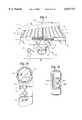
- FIG. 1contains a view of a resilient support 10 in conjunction with an air control system in accordance with the present invention.
- Resilient support 10is preferably a fluid filled bed and more preferably an air bed to accommodate one or more persons.
- Resilient support 10has a generally rectangular base or box spring unit 12 adapted to be supported on a floor or a frame engaging the floor.
- a mattress unit 14is located on top of box spring unit 12.
- Mattress unit 14has a generally panshaped resilient member 16 having upright linear side edges 18 and 20 joined to a transverse front edge 22 and a comparable transverse rear edge 24.
- a pair of side by side longitudinal air bladders 30 and 32are located in rectangular chamber 28.
- the air bladders 30 and 32comprise air mattresses or air bags that can include a plurality of transverse and/or longitudinal chambers adapted to accommodate air under pressure.
- the air bladders 30 and 32are of a size to fill rectangular chamber 28.
- Commercially available air bladdersvary in size from 23 to 34 inches wide and 67 to 84 inches long.
- the air bladders 30, 32have an inflated thickness of 5.5 inches.
- Other types and sizes of air bladders as well as bladders designed to accept other fluids, e.g. water,can be used in mattress unit 14 for resilient support 10.
- a generally rectangular cover 38fits over edges 18, 20, 22 and the rear edge 24 to enclose the top of chamber 28. As shown in FIG. 1, a portion of the cover 38 has been rolled back to illustrate the side-by-side placement of air bladders 30, 32 in rectangular chamber 28.
- the air control system 40functions to provide air under pressure to air bladders 30, 32 and to control the pressure of the air bladders 30, 32.
- the air control system 40includes a hand control unit 42 and a base unit 44.
- Hand control unit 42 shown in FIG. 2Ais preferably a remote unit physically unconnected to the remainder of the air control system 40.
- FIG. 2Bshows an alternate embodiment hand control unit 742, which comprises an analog pressure gage indicator 804, and air control buttons 806, 808.
- Hand control unit 742is preferably used with the alternate pump configuration described in relation to FIG. 16B, although it is useful with various pump configurations.
- the hand control unit 42allows a user to control the air pressure within the air bladders 30, 32 while lying on the mattress unit 14 or in any other position in the vicinity of the air control system 40.
- Hand control unit 42is preferably used with pump 152 described later below, although it is useful with various pump configurations.
- the top surface 102 of hand control unit 42contains a digital display 104, two buttons 106, 108, and a two position switch 110.
- Digital display 104presents information received from the base unit 44.
- the digital display 104is made up of a liquid crystal display (LCD).
- the LCDis made up of two digits 112 ranging from 0-9 and a half digit that can only be a 1 or unilluminated.
- each digit 112is made up of 7 segments 113, as shown in FIG. 3, and the half digit 114 is made up of two segments 115, the top and bottom of the 1.
- the liquid crystal displayis backlit by two preferably amber light emitting diodes.
- Digital display 104displays for the user a number related to the pressure within the air bladders 30, 32.
- the button(either 106 or 108) which is designed to increase the pressure in an air bladder has a protruding top portion as felt by the user, while that button designed for deflating or reducing air pressure in an air bladder is designed with a depressed top portion as felt by a user. This further optimizes the ergonomics of the hand control unit and facilitates use without even viewing the unit.
- the two buttons 106, 108 and the switch 110provide for the communication of a command from the user to the air control system 40.
- the two buttons 106, 108are adapted to be used by the user to initiate an inflation or deflation cycle, request the display of the numer related to the current pressure or to instruct the base unit 44 to recognize the hand control units 42.
- the position of two position switch 110selects the air bladder 30, 32 on which the operations of the hand control unit 42 will function.
- the top surface 102 of the hand control unit 42can include markings indicating left or right near the corresponding side of switch 110.
- the preferred convention for determining the left/right side of mattress unit 14is from the perspective of a person laying on their back with their head in the proximity to the front edge 22 (hose side) of the mattress unit 14, although other conventions can be used.
- either position of the switch 110will allow adjustment of the pressure in the air bladder 30 if a Y-hose is used to attach the base unit 42 to the mattress unit 14, as described below.
- the interior of the hand control unit 44contains a portable power supply 116, a hand control processor 118 and a hand control receiver/transmitter 120.
- the portable power supply 116is made up of a disposable battery or a rechargeable battery.
- the hand control processor 118receives input from buttons 106, 108 and base unit 44 through hand control receiver/transmitter 120 and sends output to digital display 104 and base unit 44.
- the hand control processor 118is a digital processor, for example a Motorola MC68HC05P4 microcontroller with a little more than 4 Kbytes of ROM (program) memory, 176 bytes of RAM memory, 20 I/O port pins, 1 input-only port pin, 1 timer output pin, and a 16-bit capture/compare timer.
- the software for the hand control processor 118is stored in the ROM memory during fabrication.
- the hand control processor 118is permanently encoded at manufacture with an eight bit unit ID code and a four bit revision code for the software version by the selection of appropriate resisters within the hand control unit 42.
- Hand control receiver/transmitter 120is adjusted to a proper electromagnetic frequency to receive from and transmit to base unit 44.
- the hand control receiver/transmitter 120can receive radio signals or transmit radio signals, but it cannot transmit and receive at the same time.
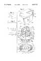
- the base unit 44 of the present inventionis depicted in FIG. 5.
- the base unit 44contains a motorized pump 152, pressure sensors 156, 158 (FIG. 10), and a base unit processing board 160 (FIG. 11).
- the base processing board 160contains the base processor 162 and the base receiver/transmitter 164.
- the base unit 44is connected to air bladders 30, 32 by way of flexible tubular lines or tubes 166, 168 through inlet receptacles 170, 172. Tubes 166, 168 allow the air control system 40 to place additional air or to remove air from the air bladders 30, 32 to achieve a desired air pressure within the air bladders 30, 32.
- tubes 166, 168can be replaced with a Y-shaped tube (not shown) so either the right or left side commands will effect the single air bladder 30 or, alternatively, the unused inlet receptacle 170, 172 can be plugged.
- An electrical plug 174is designed to be connected to a conventional ac power receptacle.
- An electrical power cord 176connects plug 174 to base unit 44.
- the base receiver/transmitter 164is tuned to an electromagnetic frequency that is preferably selected to be in the radio frequency range.
- the electromagnetic frequencyis preferably within the range from 315 MHz (106 Hz) to 350 MHz.
- the selection of the radio frequency part of the electromagnetic spectrumenables the clear transmission of the signal without the need for the user to point the hand control unit 42 at the base receiver/transmitter 164.
- the signalis transmitted in digital form at the rate of 833 bits per second.
- the base receiver/transmitter 164can receive radio signals or transmit radio signals, but it cannot transmit and receive at the same time.
- the pressure sensors 156, 158are standard piezoelectric pressure sensors such as those available from IC Sensors Inc.
- the cap on the pressure sensors 156, 158contain a small hole to allow air under ambient pressure to enter. This allows the measurement of the variation from ambient pressure by the pressure sensors 156, 158.
- the circuitry to amplify the signal from the piezoelectric sensor and to perform the analog to digital conversionis also standard in the art.
- the processor 162is a digital processor, for example Motorola MC68HC05P6 microcontroller with a little more than 4 Kbytes of ROM (program) memory, 176 bytes of RAM memory, 20 I/O port pins, 1 input-only port pin, 8-bit analog to digital converter, and a 16-bit capture/compare timer.
- the software for the processor 162is stored in the ROM memory during fabrication.
- tube 166is shown in conjunction with a tube fitting 180.
- Tube fitting 180is selectively, detachably received within an inlet receptacle 170, 172, it being understood that the tube 168 is identical in construction with tube 166.
- Fitting 180is preferably comprised of a one piece, synthetic resin, generally tubular body 182.
- the fitting body 182includes a tube receiving end 184, a body midportion 186, and male connector head 188.
- the male connector head 188includes an enlarged sealing portion 190.
- the sealing portion 190carries a sealing o-ring 192.
- Connector head 188also includes connecting tip 194.
- Connecting tip 194includes a pair of generally semi-circular in cross section prongs 195, 196.
- the prongs 195, 196are arranged on the tip 194 in mirror image fashion.
- Each of the prongs 195, 196include an axial portion 197 extending outwardly from the enlarged portion 190 of the connector head 188, and a half-circumferential portion 198 arranged in generally L-shaped fashion with the axial portion 197.
- Circumferential portion 198includes beveled perimeter 199, and a projecting boss portion 200.
- each of the inlet receptacles 170, 172include a generally tubular inner wall 201, and a boss receiving aperture 203.
- a connector head 188 of a respective hose fitting 180is detachably received within a respective receptacle 170, 172, with the sealing O-ring 192 carried by the enlarged portion 190 of the connector head 188 received in sealing contact with the receptacle internal side wall 201.
- a boss 200 of one of the two connecting head prongs 196, 197is detachably received within the aperture 203.
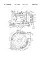
- Pump 152has three major subcomponents: pump outer housing 202, fan unit 204, and air distribution unit 206.
- Pump outer housing 202has three subcomponents: lower outer housing portion 208, upper outer housing portion 210, and flexible mount 212.
- the lower outer housing portion 208provides the mounting base for the fan unit 204 and the upper outer housing portion 210.
- the upper outer housing portion 210is mated to the lower outer housing portion 208, enclosing the fan unit 204 without physical contact therewith. Since the upper outer housing portion 210 of pump outer housing 202 is not in contact with the motor unit 204, mechanical dampening of the fan unit 204 is required only between the fan unit 204 and the lower outer housing portion 208 to which the fan unit 204 is mounted in order to minimize vibration and noise transmission.
- the lower outer housing portion 208is comprised of a base 213 and peripheral lip 214.
- Lower outer housing portion 208is preferably made of a thermoplastic material.
- the base 213is designed to be generally flat in order to facilitate being placed upon the floor proximate to the air bed.
- the peripheral lip 214has an upper margin into which interlocking marginal grooves 215 are formed.
- support posts 216 for fan unit 204are formed integral with base 213.
- the support posts 216project above the upper margin of the peripheral lip 214.
- the support posts 216have a central bore 218 defined therein to facilitate the passage of a connecting screw therethrough.
- Smaller connecting posts 219are also formed integral to base 213.
- Connecting posts 219are designed to facilitate the connection of the upper outer housing portion 210 to lower outer housing portion 208.
- a central bore 220is defined in connecting posts 219 in order to facilitate passage of a connecting screw therethrough.
- a helical wall 221is formed integral with base 213.
- Helical wall 221defines a portion of helical air intake passageway 222.
- Helical air intake passageway 222extends from central chamber 223 outward to intake mouth 224.
- Helical air intake passageway 222is defined by base 213, helical wall 221, and flexible mount 212.
- the intake mouth 224has two adjacent intake openings 225a and 225b, separated by a central support 226.
- Support tabs 228overlie supporting structure 229 formed in base 213.
- Screws 230are threaded through bores formed in support tabs 228 and then threaded into the supporting structure formed in base 213 to affix intake mouth 224 to lower outer housing portion 208.
- a nose plate 232projects from and overlies intake openings 225a and 225b.
- the nose plate 232is strengthened by gussets 234.
- a cooling air mouth 238, depicted in FIG. 12,is also affixed to lower outer housing portion 208 of pump outer housing 202.
- the cooling air mouth 238is generally located diametrically opposed to the intake mouth 224.
- Cooling air mouth 238has a cooling air intake 240 defined therein.
- the cooling air mouth 238is affixed to base 213 as previously described by means of support tabs 242 and screws 243.
- a sealing plate 244projects from and overlies the cooling air intake 240.
- the flexible mount 212is placed atop base 213 of lower outer housing portion 208.
- the central underside position of flexible mount 212is supported upon the top portion of helical wall 221.
- Flexible mount 212has a central aperture defined therein.
- the central aperture 244is in registry with central chamber 223 of helical air intake passageway 222.
- Cutouts 246are provided in flexible mount 212 to accommodate the passage of support posts 216 therethrough.
- Flexible mount 212is formed of a relatively thin lower flexible rubber portion 248 and an upwardly directed relatively thick foam rubber cushion 250.
- the foam rubber cushion 250is preferably bonded to flexible rubber portion 248.
- Flexible mount 212is formed in a generally circular shape.
- the upper outer housing portion 210 of pump outer housing 202is formed generally in an inverted bowl shape, having a top portion and side portions defining a considerable depth.
- Upper outer housing portion 210has a generally cylindrical center section 260 with squared corners 262, 263.
- the periphery of the lower portion of squared corner 262is designed to mate with the nose plate 232 of intake mouth 224.
- the periphery of the lower portion of squared corner 263is designed to mate with the sealing plate 244 of cooling air mouth 238.
- Pressurized air outlets 264are defined in squared corner 263.
- the lower margin of the side portion of upper outer housing 210has interlocking marginal lips 268 defined thereon. Interlocking marginal lips 268 are designed to mate with interlocking marginal grooves 215 formed on the margin of lip 214.
- Downwardly directed mounting posts 270are designed to be brought into registry with connecting posts 219 formed in base 213. Upwardly directed screws (not shown) are passed through the central bore 220 of connecting post 219 and threaded into mounting posts 270 to effect the mating of upper outer housing portion 210 to lower outer housing portion 208.
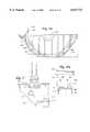
- the fan unit 204 of pump 152is best viewed in FIGS. 13 and 14 and has two major subcomponents: fan housing 280 and two stage fan 282.
- the fan unit 204is preferably fully assembled prior to installation within pump housing 202.
- the fan housing 280is formed in two halves 280a and 280b, enclosing the two stage fan 282.
- the sectional view of FIG. 14depicts housing half 280a of housing 280 with the fan 282 installed therein.
- the two halves of fan housing 280are held together by screws 276 threaded into supports 278.
- Fan housing 280has structure defining a lower impeller chamber 284.
- Lower impeller chamber 284includes a central air inlet 286 defined therein.
- Central air inlet 286is in fluid flow communication with a central chamber 223 of helical air intake passageway 222 when fan unit 204 is mounted to lower outer housing portion 208.
- Upper impeller chamber 288defines the second chamber for two stage fan 282.
- Upper impeller chamber 288has an air outlet 290 designed to exhaust pressurized air from fan unit 204.
- Lower impeller chamber 284 and upper impeller chamber 288are fluidly connected by air passageway 292, designed to convey pressurized air from lower impeller chamber 284 to the upper impeller chamber 288.
- a cylindrical core 294is formed between lower impeller chamber 284 and upper impeller chamber 288.
- Core 294has cooling air inlets 296 defined therein.
- Two O ring grooves 298are formed around the inner diameter of core 294.
- mounting slots 300are formed integral with the external portion of lower impeller chamber 284. Rubber mounting grommets 302 are inserted into mounting slots 300. Mounting grommets 302 have a central bore defined therein that is brought into registry with the central bore 218 of support posts 216.
- the two stage fan 282 of fan unit 204is a variable speed unit designed to operate at various selected speeds.
- Fan 282has a first stage impeller 306 and a second stage impeller 308.
- First stage impeller 306is rotationally mounted within lower impeller chamber 284 and second stage impeller 308 is rotationally mounted in upper impeller chamber 288.
- the impellers 306, 308are mirror images in construction and have curved impeller vanes 310 mounted on an impeller disk 312. Preferably, there are eight radially directed curbed impeller vanes 310 on each impeller 306, 308.
- the fan motor 314is mounted on an axially shaft 316 extending between first stage impeller 306 and second stage impeller 308.
- a small cooling fan 317is mounted on axially shaft 316.
- the motor 314is mounted within housing 318.
- Two cooling air inlets 320are formed within housing 318 to admit cooling air to cooling fan 317. Cooling air outlets (not shown) are formed in the bottom portion of housing 318 approximate first stage impeller 306.
- Power leads 324are brought into the top portion of housing 318 in order to power motor 314, by means of a power board 325. Power board 325 is affixed to housing 318 and is stabilized within fan housing 280 by clips 326.
- the two stage fan 282is mounted within fan housing 280 by two O rings 328.
- the O rings 328are compressively held within O ring grooves 298 of fan housing 280. No portion of the fan 282 is in physical contact with the fan housing 280. Accordingly, the two O rings 328 provide dampening of vibrations generated by the two stage fan 282, thereby minimizing the transmission of such vibrations to fan housing 280.
- FIG. 16Bshows a side schematic view of a re-oriented partial (lower portion) fan housing 280' positioned above a schematic base 213'.
- housing 280is removed to accommodate a secure contact with base 213'.
- This configurationresults in air intake at inlet 904 after routing through base 213', and then routing of the air through the central chamber and impeller chambers substantially as described above.
- the vertical rather than horizontal orientation of the fan housing 280'allows additional volume of space between housing 280' and an outer pump housing generally adjacent to air inlet 904. This is quite useful for placement of circuitry and electrical components for controlling the pump. However, the elimination of portions of the housing also re-shape the overall configuration of the pump outer housing as a smaller, more circular (in plan view) layout relative to the pump 152 shape and size described in relation to FIG. 5.
- FIG. 16Cfurther illustrates air chamber modifications to improve the efficiency of air being pressurized within housing 280'.
- Lip 945shown in shaded lines, is designed to route air in and out of the impeller chambers. However, this lip has been improved by lengthening to a new shape designated 946. Lip 946 more efficiently routes the air by extending further into the air flow.
- FIG. 16CA further air routing improvement is shown in FIG. 16C.
- This improvementis schematically similar to the lip extension in its utility with either the re-oriented pump shown in FIG. 16B or the pump 152 shown in various prior figures.
- Line 968depicts the arc of rotation of an impeller within an impeller chamber.
- Line 970depicts an inner wall of an impeller chamber, with the distance between the lines being less than about 1/4", and more preferably about 1/8". The remainder of any previous chamber volume is preferably eliminated (as shown by diagonal lines 985). The overall reduction in chamber volume reduces wasteful vortices and improves the efficiency of pumps using this improvement.
- the air distribution unit 206 of pump 152is fixedly mounted on pump outer housing 202.
- the housing 330 of air distribution unit 206is preferably made of a thermoplastic material and is conventionally coupled, in one embodiment, to fan housing 280 by screws.
- Alternate embodiment air distribution units 206'are shown in FIGS. 18B, 18C, and 18D.
- Air distribution unit 206'is designed for ease and economy of assembly by use of snap-in and snap-fit portions. These portions, such as solenoid retaining resilient fingers 331 and snap-fit portions 333, eliminate the need for assembly screws, thereby increasing assembly speed. Precise manufacturing of embodiments as shown in FIGS. 18B-18D further enhance the overall quality and competitiveness of products manufactured according to this invention.
- Air distribution unit 206has a pressurized air inlet 332 that is fluidly coupled to the air outlet 290 of upper impeller chamber 288.
- Air distribution system 206further includes a left pressurized air outlet 334 and a right pressurized outlet 336.
- the left pressurized outlet 334is connected to a flexible conduit 337a and flexible conduit 337a is connected to a pressure sensor 156.
- the right pressurized air outlet 336is similarly connected to conduit 337b which is connected to pressure sensor 158.
- Left pressurized outlet 334is in fluid communication with tube 166 which is in free pressure communication with a first air bladder 30 of the mattress unit 14.
- the right pressurized outlet 336is similarly connected to a second air bladder 32 by way of tube 168.
- the pressurized air flow to the aforementioned two bladders 30, 32is controlled by a left solenoid valve 338 and right solenoid valve 340.
- Air flowproceeds through the solenoid valves 338, 340 through inlet receptacles 170, 172 into tubes 166, 168 to achieve air communication with the air bladders 30, 32.
- Actuation of valves 338, 340withdraws the solenoid shaft 341, thereby opening the inlet receptacles 170, 172.
- flexible mount 212is first placed upon base 213 of lower outer housing portion 208.
- Flexible mount 212is positioned with respect to intake mouth 224 and cooling air mouth 238 such that air entering intake openings 225a, 225b is directed beneath flexible mount 212 and air entering cooling air intake 240 is directed above flexible mount 212.
- Fan unit 204is then placed on top of the foam rubber cushion 250 of flexible mount 212. Suitable screws 348 are passed through the central bores 218 of support posts 216 and are threadedly engaged with rubber mounting grommets 302 that are in the mounting slots 300 of fan housing 280. As these screws are tightened, the fan unit 204 is pulled into compressive engagement with the foam rubber cushion 250 of the flexible mount 212. The rubber mounting grommets 302 come into compressive engagement with the support posts 216. By this means, the fan unit 204 is held in fixed engagement with the lower outer housing portion 208 of pump outer housing 202. At the same time, vibrations generated within fan unit 204 are damped by the foam rubber cushions 250 of flexible mount 212 and the rubber mounting grommets 302.
- the service unit(not shown) performs all of the function of a hand control unit 42 in addition to various diagnostic checks of the base unit 44.
- the airis drawn from central chamber 223 of the helical air intake passageway 222 through air inlet 286 and lower impeller chamber 284.
- the airis pressurized and accelerated by the rotating of first stage impeller 306.
- Such pressurized airis then forced through air passageway 292 to the upper impeller chamber 288.
- the airis then further pressurized by the rotating second stage impeller 308.
- the pressurized airis expelled from fan housing 280 via air outlet 290 to the air distribution unit 206.
- the air distribution unit 206then distributes pressurized air to one or both of the air chambers of the air bed as determined by the left solenoid valve 338 and right solenoid valve 340.
- Cooling airis drawn in through the cooling air intake 240.
- the cooling airfloods the space defined between the upper outer housing portion 210 of pump outer housing 202 and the fan unit 204.
- the cooling airis drawn by cooling fan 317 through the cooling air inlet 296 and into the housing 318 of the two stage fan 282.
- the cooling fan 317forces the cooling air downward through motor 314 of the two stage fan 282 and out through the cooling air outlet 320.
- the cooling air outletsopen into the upper impeller chamber 288.
- the cooling airis then pressurized by the first stage impeller 306 and mixed with the air received from central air inlet 286.
- the cooling airis then provided to the air bed via the air distribution unit 206.
- the foregoing cooling air pathacts to minimize the transmission of fan vibration and noise therethrough.
- the function of the air control system 40relies on the communication link between the base unit 44 and the hand control unit 42. Communications are always initiated by either a hand control unit 42 or a service unit.
- a base unit 44transmits only in response to messages it receives from the other units.
- a preamble to the messageprovides a sequence during which the receiver can synchronize with the transmitter.
- a preferred preambleconsists of 14 zero bits followed by 2 one bits.
- Every messagecontains a 8-bit ID field which indicates the originator or addressee of the message, a 4 bit revision code which indicates the version of the software and a four bit instruction.
- Hand control units 42place their particular ID into messages that they send. All service units put the same ID, all zeros, and revision code, all zeros, into the messages that they send.
- the 8 bit IDallows for 256 different IDs for the hand control units 42 with the one reserved for service units.
- the 4 bit revision codeallows for 16 different software versions, and the 4 bit instructions allow for 16 different messages. It requires about 1200 microseconds to transmit each bit.
- a base unit 44responds to messages only from service units or from hand units 42 that it recognizes.
- a base unit 44puts the destination unit's ID in the response message.
- a base unit 44maintains a list of hand unit IDs that it recognizes, up to two. The list can be entered by any hand control unit 42 during the first 256 secs. after the base unit 44 is powered on. This facilitates the initialization of the list of recognized hand control units 42. If there is a power outage or the base station is unplugged, previously entered IDs will be remembered by the base unit 44, and reinitialization will not be required.
- the hand unit introduction proceduredescribed below, can be used by a recognized hand control unit 42 whenever the base unit 44 is not busy with an adjustment. The hand unit introduction procedure completely rewrites the list of recognized hand control unit IDs.
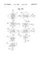
- the hand control processor 118responds basically to the pressing of one or both buttons 106, 108. Referring to FIG. 19a, if the hand control processor 118 determines that neither button 106, 108 is being pressed at step 400, the hand control processor 118 determines whether the unit is currently in the sleep mode or not at step 401. If it was in the sleep mode, the hand control unit 42 continues in the sleep mode 402. If it was not in the sleep mode at step 401, the hand control processor 118 next determines whether 10 seconds have passed without activity at step 408, as depicted in FIG. 19a. The buttons 106, 108 are checked every tenth of a second.
- step 408proceeds to step 410 where the digital display 104 is turned off, and the hand control unit 42 enters the sleep mode to conserve power. If 10 seconds have not passed without activity, the hand control processor 118 checks at step 403 if buttons had been disabled and the disabling condition has been removed. If there were disabled buttons, the buttons are freed from being disabled at step 404, and the processor continues with step 400. If at step 403, it is determined that no buttons are disabled, the hand control processor 118 continues with step 400.
- the hand control processor 118determines that a button 106, 108 is being pressed at step 400, the hand control processor 118 initiates the processing of the signal from the buttons 411. First, it is determined whether the control is in its active state at step 412. If the hand control unit 42 was in sleep mode when the button 106, 108 was pressed, it switches to wake-up mode (step 414). At wake up 414, the hand control unit 42 zeros its RAM memory, turns on the power to the display 104 and initializes much of the rest of the system.
- the hand control processor 118After a wake-up mode is initiated at step 414, the hand control processor 118 requests the current pressure 416 from the base unit 44 by way of the hand control transmitter/receiver 120 at step 418, to show a pressure measurement sampled within the last 30 seconds. A response from base unit 44 is received and decoded 419, and the display 104 is updated 420. Then, the hand control processor 118 sets a timer counting 422, and returns to determine again if a button 106, 108 is depressed 400 when the appropriate time to check the buttons is reached. The value from the timer can be used for the later determination of how long the button has been depressed.
- step 412If at step 412 the hand control unit 42 was in an awake mode, it is determined which buttons are depressed at step 424. To make this determination, the hand control unit 42 reads the buttons 106, 108, every tenth of a second and updates a byte that shows which buttons are pressed. The relatively slow sampling rate provides an effective means of debouncing the buttons.
- the hand control processor 118determines if the buttons are disabled 426. If the buttons are disabled at step 426, the program continues with step 400. If the buttons are not disabled, the program continues with step 428. The hand control processor 118 keeps track of the buttons 106, 108 that were pressed on the previous reading.
- buttonsare depressed which had been depressed at the last determination 428. If different buttons are depressed, the buttons are disabled at step 430, and they remain disabled until released, see step 403. The program then continues with step 400. Buttons are also disabled when an adjustment is active (not shown).
- buttonsare not disabled at step 428. After determining that the buttons are not disabled at step 428, it is determined how many buttons are depressed 432. If one button is depressed at step 432, it is determined if the button has been depressed for two seconds 434. If not, the program continues with step 400. If yes, the digital display 104 is incremented or decremented appropriately depending on which button 106, 108 is depressed 436. Initially, an increment or decrement is processed every 0.5 secs. that the button is held, but after four consecutive actions the rate is accelerated to an increment or decrement every 0.1 secs. Also, the hand control processor 118 sends a message 438 that is transmitted 439 to base unit 44 to begin an adjustment of the pressure. To indicate that an adjustment is in progress, the digital display 104 is made to blink 440. Then, the hand control processor 118 resets the timer counting the length of time that the button has been depressed 442, and the program returns to step 400.
- step 432determines that two buttons 106, 108 are depressed 444
- the hand unit processorproceeds as is depicted in FIG. 19c.
- the statusis checked 446, and the hand unit introduction procedure is initiated if it is not already in progress. This procedure is purposely cumbersome in order to prevent accidental modification of the list of recognized hand control units 40.
- the displaystarts to count down at step 448 from 10 to 1.
- the displayshows two hyphens (--) 450, and the hand control unit 40 sends a message 452 which is transmitted 453 to the base unit 44.
- the base unit 44receives the message, it rewrites the ID list to contain only the ID of the sender hand control unit 42.
- the base unit 44sends an acknowledgement to the hand control unit 42.
- the hand control unit 42receives the acknowledgement at step 456, it displays "C1" or "C2" at step 458 as instructed by the base unit 44.
- the userAfter the first message is received by the base unit 44, the user has one minute to complete the hand unit introduction procedure. If the user wants the list to contain only one ID, there are two options. First, the user can press both buttons again, see step 444. This situation is depicted in the second branch in FIG. 19c for the case where the introduction procedure is already in progress.
- the hand control process 118sends a message 460 that is then transmitted 461 to the base unit 44 that there is only one hand control unit 42. After the message is sent, hyphens are again shown on the display 462.
- the base unit 44sends an acknowledgement that causes the display of the hand control unit 42 to display (1C) 466. A short time later, the base unit 44 sends an instruction for the hand control unit 42 to resume normal operation 468. Then, the hand control process 118 continues with step 400.
- the usercan do nothing for about one minute after "C1" is displayed at step 458. If the base unit 44 has not received a second message by the end of the minute, the base unit 44 sends a message that causes the hand control unit 42 to stop displaying "C1" and to return to normal operating mode. (This option is not depicted in the FIG. 19c since the hand control unit does not make the determination.)
- the usercan go to the second hand control unit 42 and press both buttons step 444 within one minute while the first hand control unit 42 displays "C1".
- the processingwould proceed along the path where the hand control unit had not initiated the introduction procedure.
- the display of the second hand control unit 42starts to count down 448 from 10 to 1.
- the display of the second hand control unit 42shows two hyphens (--) 450, and the hand control unit 42 sends a message 452 to the base unit 44.
- the base unit 44receives this second message in the procedure, it adds the second ID to the list. Then, the base unit 44 sends an acknowledgement to the second hand control unit 42.
- the display of the second hand control unit 42shows "C2" 458.
- the base unit 44sends messages to both hand control units 42, causing them to stop displaying "C1" or "C2" and to return to normal operating mode.
- the hand unit introduction messageis the only operation that elicits two responses from a base unit 44, the acknowledgement message and the done message.
- the hand control unit softwaremaintains two display buffers of three bytes each in its RAM memory.
- the secondary buffercontains information with each byte corresponding to a display digit 112 or half digit.
- Information in the primary bufferis organized according to the segments 113, 115 of the display 104.
- conflictscan occur in two cases.
- the first conflictoccurs if a hand control unit 42 tries to monitor an air bladder's pressure when the base unit 44 is already adjusting the pressure in the same air bladder 30, 32.
- the second opportunity for conflictoccurs if a hand control unit 42 tries to adjust an air bladder's firmness when the base unit 44 is already adjusting the pressure in either air bladder 30, 32 in response to a request by another hand control unit 42.
- the base unit 44will notify the requesting hand control unit 42 that it is busy and cannot currently satisfy the request. This causes the second hand control unit to display blinking hyphens (--).
- the second hand control unit 42When the second hand control unit 42, displays blinking hyphens, it ignores depression of the increment/decrement buttons 106, 108, i.e., the buttons are effectively disabled as long as a pressure adjustment is occurring under the instruction of the first hand control unit 42.
- the hand unitdoes check for changes in the two position switch 110. When the position of the two position switch 110 is changed, the hand control unit 42 notifies the base unit 44, and the base unit 44 transmits the pressure of the newly selected air bladder 30, 32 to the hand control unit 42 while not terminating the active adjustment of the other air bladder 30, 32 as instructed by the other hand control unit 42.
- the digital display 104will display various error codes in response to various communication difficulties with base unit 44 and if the motor 152 is too hot to make an adjustment.
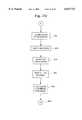
- FIG. 20displays the process of receiving and decoding a message from the base unit.
- a counteris set to one 480, and a message is transmitted 482 to base unit 44.
- hand control processor 118checks 486 if a valid response was received from the base unit 44. If a valid response was received, the response is processed 488 and the processor returns 490 to the programming step awaiting the response. If a valid response was not received, the counter is checked to determine if 7 attempts at transmission have been made 492. If 7 attempts have been made, an error message is sent to the digital display 104 and the program returns to step 400. If 7 attempts had not been made at step 488, the counter is incremented by one 496, and the hand control process 114 returns to step 482 to continue with the transmission loop.
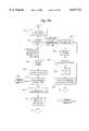
- the software for the base processor 162has a main loop in which the processor spends most of its time. Referring to FIG. 21, the base processor 162 updates various timers if a second has elapsed since the last update 602, checks if a message has been received but not yet processed 604 and checks if a time dependent action needs to be formed 606.
- the base unit 44responds only when instructed by a hand control unit 42 except for monitoring the pressure which occurs every 30 seconds if no other activity is taking place. The base unit 44 sends a response for every message received from a recognized hand control unit 42.
- the base unit 44In order to reduce the chance of a base unit 44 taking an undesirable action because of an erroneously received message, the base unit 44 only accepts a message from a hand control unit 42 within 256 secs. of power up of the base unit 44 or within 256 secs. of the receipt of a previous acceptable message from the hand control unit 42, unless the message received is just requesting the current status. Similarly, base unit 44 only accepts messages from a service unit within five minutes of power up or within five minutes of receipt of a previous acceptable message from the service unit. As each byte is received, the message is stored in a reception buffer.
- the processordetermines if a message has been received 608 and is waiting for processing, see FIG. 22. If there is a message to be processed, the message is decoded 610. If the current pressure was requested 612, the pressure last measured is transmitted 614 to the hand control unit 42. If the message initiated a inflation/deflation request or the hand unit introduction procedure, the processor is notified 616 that an activity is requested, and the program returns to the main loop 604.
- FIG. 23depicts the various paths the base processor 162 can follow when a process action is required at step 606. If at step 606, the base processor 162 determines that an action is required 618, the processor proceeds to determine which action is required (see FIG. 19a): hand unit introduction in progress 620, pressure needs to be read 622, adjustment in progress 624, adjustment request is pending 626.
- a hand unit introduction procedurecan be initiated by a recognized hand control unit 42 whenever the base unit 44 is not busy with an adjustment. The procedure can be initiated by any hand control unit 42 during the first 256 secs. after the base unit 44 is powered on.
- the base processor 162when the base unit 44 receives the first hand unit introduction message, the base processor 162 rewrites the ID list 628 to contain only the ID of the sender hand control unit 42. Then, the base unit 44 sends an acknowledgement 630 that is transmitted 631 to the hand unit 42.
- the base processor 162sets a timer 632. The base processor 162 monitors the timer for one minute to determine 634 if a second hand unit introduction message is received. If no other messages are received within this minute, the base processor 162 concludes that there is only one hand control unit 42, sends a message 636 to return to normal operation that is transmitted 637 to the hand control unit 42, and the base processor 162 ends the hand unit introduction procedure and returns to the main loop 606.
- the base processor 162determines 638 if the ID is the same as the first ID received. If the second ID is different, the base processor 162 adds the second ID to the list of IDs 640. Then, the base unit 44 sends a message 642 that is transmitted 643 to the second hand control unit 42. If the second message originated from the same hand control unit 42 as the first message, the base unit sends a message 644 that is transmitted 645 to the hand control unit 42 acknowledging that there is only one hand control unit 42. In either case, after a couple of seconds, the base unit sends a message 646 that is transmitted 647 to the one or to both units to return to normal operation.
- the pressureis read every 30 seconds if no adjustment is taking place. As described below, the pressure is also read every 3 seconds during an active adjustment. Note that during an active adjustment, the hand control unit 42 sends a request for the pressure every 10 secs. while continuing to display the flashing target pressure. At each request, the base unit 44 transmits to the hand control unit 42 the last pressure read as in step 612. Referring to FIG. 23c, to read the pressure, the base processor 162 first closes 648 the valves 338, 340 if necessary. Three seconds are allowed to pass 650 to let the pressure in the air bladders 30, 32 to stabilize. The base processor 162 then initiates the analog-to-digital (A/D) conversion 652 of the output of the pressure sensors 156, 158. Then, the base processor 162 waits 0.1-0.2 second 654 before calculating the pressure 656 from the digitized reading. The pressure is obtained from the following formula:
- Gain and the Offsetare determined when the unit is calibrated during manufacture or service.
- the values for Gain and Offsetare stored in the base processor's memory.
- the calculated pressureis stored as a 24 bit number with a maximum resolution of 0.005 psi.
- the actual number displayed by the hand control unit 42can have various relationships to the pressure. It can be an actual expression of the pressure in appropriate units, or it can be a value scaled to some arbitrary and convenient units. This scaling can be linear or non linear. A preferred relationship between the displayed value and the pressure is
- a linear relationshipcan be used between the displayed value and the pressure with zero pressure corresponding to a zero display and a maximum pressure of 0.65 psig corresponding to a displayed value of 100.
- the base processor 162examines whether the estimated inflation/deflation period has ended 658. If it has not, the program checks to see if 3 secs. have passed since the pressure has been measured. If 3 secs. have passed, the processor measures the pressure 660, as described above. The current pressure is compared with the requested pressure 662. If the calculated pressure is within 0.01 psi of the requested (target) pressure, the base processor 162 returns to the main loop 606 since no more adjustment will be undertaken. If the pressure is not within 0.01 psi of the requested pressure, the base processor 162 resets a timer to count 3 secs. and returns to the main loop at step 606. As an alternative to checking the pressure every 3 secs.
- the back pressurecan be monitored with the valve 338, 340 open. This back pressure can be correlated by the manufacturer to correspond to a particular bladder 30, 32 pressure with the valve 338, 340 closed. Then, the pressure could be checked with the valve 338, 340 closed after the termination of the adjustment process to check the final value of the adjustment.
- the current pressureis calculated at step 662 by the procedure described above.
- the base unitterminates the adjustment, even if the current pressure is not within 0.01 psi of the requested pressure. Also, if the base reads an identical pressure of at least 0.35 psi while inflating a chamber, the base processor 162 determines that a "stall" condition exists and terminates the adjustment.
- the program for the base processor 162implements a thermal model of the motor 152.
- the modelassumes the following relationship of the temperature above ambient temperature with time:
- T asymptis dependent on the motor speed.
- khas a value of 0.002 when the motor is off and a value of 0.006 when the motor is on. For small steps in time, this equation leads to the following difference equation:
- the base processor 162sets a flag in RAM, turns the motor on at low speed to facilitate cooling and refuses to begin another adjustment until the estimated (model) temperature drops below 120 degrees above ambient temperature.
- the valve 338, 340will be closed during the cooling process unless the base processor 162 determines that a useful adjustment can be made with the valve 338, 340 open at the motor speed during cooling.
- the programclears the flag and again accepts adjustment requests. If the flag is set when the base unit 44 is powered on, the base unit software initializes the temperature to 170 degrees above ambient, turns the motor on low speed to facilitate cooling and refuses to begin an adjustment until the estimated temperature drops below 120 degrees.
- the base processor 162determines that an adjustment request is pending, first the current pressure is calculated at step 666, as described above. The current pressure is compared with the requested pressure 668. If the current pressure is within 0.01 psi of the requested pressure, no adjustment is necessary 670, and the program continues in the main loop 606. If the difference is greater than 0.01 psi, it is determined whether inflation or deflation is necessary at step 672.
- the base processor 162determines the appropriate motor speed 674. When inflating from pressures below 0.40 psig, the motor is run at medium speed. When inflating from greater pressures, the motor is run at high speed. The base processor 162 next calculates an estimate of the required time at step 676 up to a maximum of 256 secs. Also at this step, the number is stored in an 8-bit counter.
- the motorized pump 152is started at step 678.
- the motoris started at low speed with stepwise increases in the speed every two seconds until the required speed is reached.
- the motoris run at a total of five speeds.
- Low, medium and highare primary speeds, i.e. they are used as final target speeds.
- Low-medium and medium-highare used only to make the transitions between primary speeds more gradual and therefore, less audibly annoying.
- the appropriate solenoid valve 338, 340 corresponding to the correct chamberis opened 680. With the adjustment in progress, the program returns to the main loop 606.
- the motor speedis determined at step 682. When deflating from pressures below 0.40 psig, the motor is off. When deflating from greater pressures, the motor is run at low speed. Then, the base processor 162 calculates an estimate of the amount of time 684 required for the adjustment up to a maximum of 256 secs. The motor is started if necessary at step 686. When the motor reaches the appropriate speed, the appropriate solenoid valve 338, 340 corresponding to the correct chamber is opened at step 688. With the adjustment in progress, the program returns to the main loop 606.
- the base unit 44When the base unit 44 is inflating an air chamber 30, 32, it reads the pressure about half a second after the valve is opened to measure the back pressure. Waiting a half second is necessary to obtain a stable back pressure reading. If the base processor 162 calculates a pressure of less than 0.15 psi, it determines that the base unit 44 is not connected to an air bladder 30, 32 and terminates the adjustment.
Landscapes
- Engineering & Computer Science (AREA)
- Mechanical Engineering (AREA)
- General Engineering & Computer Science (AREA)
- Computer Networks & Wireless Communication (AREA)
- Signal Processing (AREA)
- Invalid Beds And Related Equipment (AREA)
- Mattresses And Other Support Structures For Chairs And Beds (AREA)
- Duct Arrangements (AREA)
- Air-Flow Control Members (AREA)
- Structures Of Non-Positive Displacement Pumps (AREA)
- Flow Control (AREA)
- Separation By Low-Temperature Treatments (AREA)
Abstract
Description
Pressure=Gain * (Reading-Offset)
______________________________________ Hand Controller Value Pressure Value (psig) ______________________________________ 00 <0.16 05 0.16 10 0.18 15 0.20 20 0.22 25 0.24 30 0.26 35 0.28 40 0.30 45 0.32 50 0.34 55 0.36 60 0.38 65 0.40 70 0.42 75 0.44 80 0.47 85 0.50 90 0.55 95 0.60 100 0.65 ______________________________________
T=T.sub.asympt +C e.sup.(-kt).
T(n+1)=T(n)+k* Δt*(T.sub.asympt -T(n)),
Claims (25)
Priority Applications (2)
| Application Number | Priority Date | Filing Date | Title |
|---|---|---|---|
| US09/253,572US6037723A (en) | 1994-11-01 | 1999-02-19 | Air control system for an air bed |
| US09/685,927US6483264B1 (en) | 1994-11-01 | 2000-10-10 | Air control system for an air bed |
Applications Claiming Priority (4)
| Application Number | Priority Date | Filing Date | Title |
|---|---|---|---|
| US08/332,833US5509154A (en) | 1994-11-01 | 1994-11-01 | Air control system for an air bed |
| US08/536,330US5652484A (en) | 1994-11-01 | 1995-09-29 | Air control system for an air bed |
| US08/827,397US5903941A (en) | 1994-11-01 | 1997-03-27 | Air control system for an air bed |
| US09/253,572US6037723A (en) | 1994-11-01 | 1999-02-19 | Air control system for an air bed |
Related Parent Applications (1)
| Application Number | Title | Priority Date | Filing Date |
|---|---|---|---|
| US08/827,397ContinuationUS5903941A (en) | 1994-11-01 | 1997-03-27 | Air control system for an air bed |
Related Child Applications (1)
| Application Number | Title | Priority Date | Filing Date |
|---|---|---|---|
| US47159299AContinuation | 1994-11-01 | 1999-12-23 |
Publications (1)
| Publication Number | Publication Date |
|---|---|
| US6037723Atrue US6037723A (en) | 2000-03-14 |
Family
ID=26988412
Family Applications (5)
| Application Number | Title | Priority Date | Filing Date |
|---|---|---|---|
| US08/332,833Expired - LifetimeUS5509154A (en) | 1994-11-01 | 1994-11-01 | Air control system for an air bed |
| US08/536,330Expired - LifetimeUS5652484A (en) | 1994-11-01 | 1995-09-29 | Air control system for an air bed |
| US08/827,397Expired - LifetimeUS5903941A (en) | 1994-11-01 | 1997-03-27 | Air control system for an air bed |
| US09/253,572Expired - LifetimeUS6037723A (en) | 1994-11-01 | 1999-02-19 | Air control system for an air bed |
| US09/685,927Expired - Fee RelatedUS6483264B1 (en) | 1994-11-01 | 2000-10-10 | Air control system for an air bed |
Family Applications Before (3)
| Application Number | Title | Priority Date | Filing Date |
|---|---|---|---|
| US08/332,833Expired - LifetimeUS5509154A (en) | 1994-11-01 | 1994-11-01 | Air control system for an air bed |
| US08/536,330Expired - LifetimeUS5652484A (en) | 1994-11-01 | 1995-09-29 | Air control system for an air bed |
| US08/827,397Expired - LifetimeUS5903941A (en) | 1994-11-01 | 1997-03-27 | Air control system for an air bed |
Family Applications After (1)
| Application Number | Title | Priority Date | Filing Date |
|---|---|---|---|
| US09/685,927Expired - Fee RelatedUS6483264B1 (en) | 1994-11-01 | 2000-10-10 | Air control system for an air bed |
Country Status (17)
| Country | Link |
|---|---|
| US (5) | US5509154A (en) |
| EP (2) | EP0789976B1 (en) |
| JP (3) | JP3824640B2 (en) |
| KR (1) | KR970707691A (en) |
| CN (1) | CN1170491A (en) |
| AT (1) | ATE369015T1 (en) |
| AU (2) | AU692687B2 (en) |
| CA (3) | CA2538933C (en) |
| CZ (1) | CZ297809B6 (en) |
| DE (1) | DE69535545T2 (en) |
| ES (1) | ES2292170T3 (en) |
| FI (1) | FI971849L (en) |
| IL (3) | IL127839A (en) |
| MX (1) | MX9703190A (en) |
| NO (1) | NO322189B1 (en) |
| NZ (1) | NZ297205A (en) |
| WO (1) | WO1996013947A1 (en) |
Cited By (130)
| Publication number | Priority date | Publication date | Assignee | Title |
|---|---|---|---|---|
| US6302145B1 (en)* | 1997-08-25 | 2001-10-16 | Hill-Rom Services, Inc. | Valve assembly |
| WO2002028230A1 (en)* | 2000-10-04 | 2002-04-11 | Northpole, Ltd. | Air bed with elevated and self-expanding support structure |
| US6378152B1 (en)* | 1995-11-30 | 2002-04-30 | Hill-Rom Services, Inc. | Mattress structure |
| US6421858B1 (en)* | 1999-07-15 | 2002-07-23 | Doc Ag | Mattresses or cushions |
| US6460209B1 (en) | 1995-11-30 | 2002-10-08 | Hill-Rom Services, Inc. | Mattress structure |
| US20030192127A1 (en)* | 1998-08-24 | 2003-10-16 | The Nautilus Group, Inc. | Air bed |
| US20040031103A1 (en)* | 2000-11-07 | 2004-02-19 | Wyatt Charles C | Therapeutic mattress assembly |
| US20040064895A1 (en)* | 2002-10-07 | 2004-04-08 | Hochschild Arthur A. | Stabilized shape retentive air-inflated bed |
| US20050005363A1 (en)* | 2001-10-30 | 2005-01-13 | Gualtiero Giori | Pressure adjustable foam support apparatus |
| US6865825B2 (en) | 1994-04-14 | 2005-03-15 | Promdx Technology, Inc. | Ergonomic systems and methods providing intelligent adaptive surfaces and temperature control |
| US20050166326A1 (en)* | 2002-04-11 | 2005-08-04 | Chaffee Robert B. | Body support, comfort device |
| US20060032188A1 (en)* | 2001-03-30 | 2006-02-16 | Chaffee Robert B | Membrane deflation in combination with rigid surfaces |
| US20060053560A1 (en)* | 2004-09-13 | 2006-03-16 | The Coleman Company, Inc. | Airbed with built-in air pump |
| US20060053561A1 (en)* | 2004-09-13 | 2006-03-16 | The Coleman Company, Inc. | Airbed with built-in air pump |
| US20060058587A1 (en)* | 2004-09-10 | 2006-03-16 | Heimbrock Richard H | Wireless control system for a patient-support apparatus |
| US20060075569A1 (en)* | 2002-09-17 | 2006-04-13 | Gino Giori | Adjustable foam mattress |
| US20060174417A1 (en)* | 2005-02-08 | 2006-08-10 | Sc Plastics, Llc | Multiple chamber fluid pressurizable mattress |
| US20060179577A1 (en)* | 2002-04-11 | 2006-08-17 | Chaffee Robert B | Body support comfort device |
| US7107706B1 (en)* | 1997-08-14 | 2006-09-19 | Promdx Technology, Inc. | Ergonomic systems and methods providing intelligent adaptive surfaces and temperature control |
| US20060260054A1 (en)* | 2004-12-23 | 2006-11-23 | Lubbers David P | Wireless control system for a patient support apparatus |
| US20070056114A1 (en)* | 2005-09-09 | 2007-03-15 | Corey Lewison | Multi-zone coil construction airbed |
| US7204041B1 (en)* | 1997-08-14 | 2007-04-17 | Promdx Technology, Inc. | Ergonomic systems and methods providing intelligent adaptive surfaces |
| US20080000029A1 (en)* | 2005-02-08 | 2008-01-03 | Rapid Air Llc (A Wisconsin Limited Liability Company) | Multiple chamber foam air mattress |
| US20080181795A1 (en)* | 2007-01-26 | 2008-07-31 | Rapid Air Llc (A Wisconsin Limited Liability Company) | Multiple configuration air mattress pump system |
| US20080229508A1 (en)* | 2000-05-17 | 2008-09-25 | Chaffee Robert B | Inflatable device with recessed fluid controller and modified adjustment device |
| EP1848388A4 (en)* | 2005-02-18 | 2009-08-26 | Smiths Medical Asd Inc | SYSTEM FOR ENSURING OPTIMAL INFLATION OF TEMPERATURE-CONTROLLED MULTIPLE COVERINGS AND METHOD THEREOF |
| US20090212925A1 (en)* | 2008-02-22 | 2009-08-27 | Schuman Sr Richard Joseph | User station for healthcare communication system |
| US20100071130A1 (en)* | 2008-09-23 | 2010-03-25 | Jacobo Frias | Inflatable temperature control system |
| US20100281619A1 (en)* | 2009-05-08 | 2010-11-11 | R & D Products, Llc | Air mattress system with inflatable limb chamber |
| US7849545B2 (en) | 2006-11-14 | 2010-12-14 | Hill-Rom Industries Sa | Control system for hospital bed mattress |
| US20100325807A1 (en)* | 2009-06-26 | 2010-12-30 | Hsin-Tsai Wu | Air pumping device, air pumping method, and airbed assembly |
| US8090478B2 (en) | 2005-06-10 | 2012-01-03 | Hill-Rom Services, Inc. | Control for pressurized bladder in a patient support apparatus |
| US8162009B2 (en) | 2006-04-04 | 2012-04-24 | Chaffee Robert B | Method and apparatus for monitoring and controlling pressure in an inflatable device |
| US20120144588A1 (en)* | 2010-12-08 | 2012-06-14 | Heimbrock Richard H | Mattress bladder boosting during chair egress |
| US8225444B2 (en) | 2001-07-10 | 2012-07-24 | Chaffee Robert B | Inflatable device forming mattresses and cushions |
| USD670658S1 (en)* | 2012-01-05 | 2012-11-13 | L & P Property Management Company | Furniture remote control |
| US20130061399A1 (en)* | 2011-09-12 | 2013-03-14 | Douglas Allen Dewell | Air Mattress Having Only Two Inflate/Deflate Ports For Inflating Four Or Six Separate Bladders |
| USD678217S1 (en)* | 2011-05-24 | 2013-03-19 | Dewertokin Gmbh | Switch |
| USD678847S1 (en)* | 2011-05-24 | 2013-03-26 | Dewertokin Gmbh | Switch |
| US8413278B2 (en) | 2006-04-04 | 2013-04-09 | Robert B. Chaffee | Method and apparatus for monitoring and controlling pressure in an inflatable device |
| US8413674B2 (en) | 2000-05-17 | 2013-04-09 | Robert B. Chaffee | Valve with electromechanical device for actuating the valve |
| USD697874S1 (en)* | 2013-03-15 | 2014-01-21 | Select Comfort Corporation | Remote control |
| US8776293B2 (en) | 2001-03-30 | 2014-07-15 | Robert B. Chaffee | Pump with axial conduit |
| US20140259419A1 (en)* | 2013-03-14 | 2014-09-18 | Select Comfort Corporation | Partner snore feature for adjustable bed foundation |
| US8973183B1 (en) | 2014-01-02 | 2015-03-10 | Select Comfort Corporation | Sheet for a split-top adjustable bed |
| US9131781B2 (en) | 2012-12-27 | 2015-09-15 | Select Comfort Corporation | Distribution pad for a temperature control system |
| US9345335B2 (en) | 2010-09-27 | 2016-05-24 | Gualtiero G. Giori | Pressure control and feedback system for an adjustable foam support apparatus |
| US9370457B2 (en) | 2013-03-14 | 2016-06-21 | Select Comfort Corporation | Inflatable air mattress snoring detection and response |
| US9392879B2 (en) | 2013-03-14 | 2016-07-19 | Select Comfort Corporation | Inflatable air mattress system architecture |
| US20160208795A1 (en)* | 2015-01-20 | 2016-07-21 | Hao Hsu | Sleeping system |
| US9445751B2 (en) | 2013-07-18 | 2016-09-20 | Sleepiq Labs, Inc. | Device and method of monitoring a position and predicting an exit of a subject on or from a substrate |
| US9504416B2 (en) | 2013-07-03 | 2016-11-29 | Sleepiq Labs Inc. | Smart seat monitoring system |
| US9510688B2 (en) | 2013-03-14 | 2016-12-06 | Select Comfort Corporation | Inflatable air mattress system with detection techniques |
| US9635953B2 (en) | 2013-03-14 | 2017-05-02 | Sleepiq Labs Inc. | Inflatable air mattress autofill and off bed pressure adjustment |
| US9730524B2 (en) | 2013-03-11 | 2017-08-15 | Select Comfort Corporation | Switching means for an adjustable foundation system |
| US9737153B2 (en) | 2001-07-10 | 2017-08-22 | Robert B. Chaffee | Configurable inflatable support devices |
| US9737154B2 (en) | 2008-04-04 | 2017-08-22 | Select Comfort Corporation | System and method for improved pressure adjustment |
| US9770114B2 (en) | 2013-12-30 | 2017-09-26 | Select Comfort Corporation | Inflatable air mattress with integrated control |
| US9844275B2 (en) | 2013-03-14 | 2017-12-19 | Select Comfort Corporation | Inflatable air mattress with light and voice controls |
| USD809843S1 (en) | 2016-11-09 | 2018-02-13 | Sleep Number Corporation | Bed foundation |
| USD812393S1 (en) | 2016-09-15 | 2018-03-13 | Sleep Number Corporation | Bed |
| US9924813B1 (en) | 2015-05-29 | 2018-03-27 | Sleep Number Corporation | Bed sheet system |
| US10092242B2 (en) | 2015-01-05 | 2018-10-09 | Sleep Number Corporation | Bed with user occupancy tracking |
| US10123626B2 (en)* | 2013-11-18 | 2018-11-13 | Logicdata Electronic & Software Entwicklungs Gmbh | Manual operating unit, manual operating system, furniture control system, bed and armchair |
| US10136815B2 (en) | 2012-09-24 | 2018-11-27 | Physio-Control, Inc. | Patient monitoring device with remote alert |
| US10143312B2 (en) | 2014-04-15 | 2018-12-04 | Sleep Number Corporation | Adjustable bed system |
| US10149549B2 (en) | 2015-08-06 | 2018-12-11 | Sleep Number Corporation | Diagnostics of bed and bedroom environment |
| US10182661B2 (en) | 2013-03-14 | 2019-01-22 | Sleep Number Corporation and Select Comfort Retail Corporation | Inflatable air mattress alert and monitoring system |
| US10194753B2 (en) | 2013-03-14 | 2019-02-05 | Sleep Number Corporation | System and method for adjusting settings of a bed with a remote control |
| US10285508B2 (en) | 2014-01-02 | 2019-05-14 | Sleep Number Corporation | Adjustable bed system with split head and split foot configuration |
| US10342358B1 (en) | 2014-10-16 | 2019-07-09 | Sleep Number Corporation | Bed with integrated components and features |
| US10441087B2 (en) | 2015-02-24 | 2019-10-15 | Sleep Number Corporation | Mattress with adjustable firmness |
| US10448749B2 (en) | 2014-10-10 | 2019-10-22 | Sleep Number Corporation | Bed having logic controller |
| US10539170B2 (en) | 2015-12-31 | 2020-01-21 | Sleep Number Corporation | Foundation and frame for bed |
| US10575654B2 (en) | 2016-10-28 | 2020-03-03 | Sleep Number Corporation | Air manifold |
| US10674832B2 (en) | 2013-12-30 | 2020-06-09 | Sleep Number Corporation | Inflatable air mattress with integrated control |
| US10677232B2 (en) | 2016-10-28 | 2020-06-09 | Sleep Number Corporation | Pump with vibration isolators |
| US10729253B1 (en) | 2016-11-09 | 2020-08-04 | Sleep Number Corporation | Adjustable foundation with service position |
| US10736432B2 (en) | 2014-07-18 | 2020-08-11 | Sleep Number Corporation | Automatic sensing and adjustment of a bed system |
| US10750875B2 (en) | 2014-01-02 | 2020-08-25 | Sleep Number Corporation | Adjustable bed system having split-head and joined foot configuration |
| US10772438B2 (en) | 2017-08-23 | 2020-09-15 | Sleep Number Corporation | Air system for a bed |
| US10827846B2 (en) | 2016-10-28 | 2020-11-10 | Sleep Number Corporation | Bed with foot warming system |
| US10851795B2 (en) | 2015-10-16 | 2020-12-01 | Intex Marketing, Ltd. | Multifunctional air pump |
| US10888173B2 (en) | 2016-10-28 | 2021-01-12 | Sleep Number Corporation | Air controller with vibration isolators |
| US10957335B2 (en) | 2017-12-28 | 2021-03-23 | Sleep Number Corporation | Home automation having user privacy protections |
| USD916745S1 (en) | 2019-05-08 | 2021-04-20 | Sleep Number Corporation | Display screen or portion thereof with graphical user interface |
| US10993546B2 (en) | 2016-10-28 | 2021-05-04 | Sleep Number Corporation | Noise reducing plunger |
| US11001447B2 (en) | 2018-09-05 | 2021-05-11 | Sleep Number Corporation | Lifting furniture |
| USD919333S1 (en) | 2019-08-27 | 2021-05-18 | Casper Sleep Inc. | Mattress |
| US11020298B2 (en) | 2009-08-31 | 2021-06-01 | Sleep Number Corporation | Climate-controlled topper member for beds |
| US11058226B2 (en) | 2016-12-08 | 2021-07-13 | Intex Marketing Ltd. | Recessed air pump |
| US11058227B2 (en) | 2015-04-23 | 2021-07-13 | Sealy Technology, Llc | Systems and methods for adjusting the firmness and profile of a mattress assembly |
| USD927889S1 (en) | 2019-10-16 | 2021-08-17 | Casper Sleep Inc. | Mattress layer |
| US11116326B2 (en) | 2017-08-14 | 2021-09-14 | Casper Sleep Inc. | Mattress containing ergonomic and firmness-regulating endoskeleton |
| US11140999B2 (en) | 2016-11-09 | 2021-10-12 | Select Comfort Corporation | Bed with magnetic couplers |
| USD932808S1 (en) | 2016-11-09 | 2021-10-12 | Select Comfort Corporation | Mattress |
| US11191687B2 (en)* | 2017-04-29 | 2021-12-07 | Harikrishan S. Sachdev | Portable cushion and method of use |
| US11202517B2 (en) | 2014-04-21 | 2021-12-21 | Casper Sleep Inc. | Mattress |
| US11241100B2 (en) | 2018-04-23 | 2022-02-08 | Casper Sleep Inc. | Temperature-regulating mattress |
| US11376178B2 (en) | 2018-11-14 | 2022-07-05 | Sleep Number Corporation | Using force sensors to determine sleep parameters |
| US11399636B2 (en) | 2019-04-08 | 2022-08-02 | Sleep Number Corporation | Bed having environmental sensing and control features |
| US11424646B2 (en) | 2019-04-16 | 2022-08-23 | Sleep Number Corporation | Pillow with wireless charging |
| US11439345B2 (en) | 2006-09-22 | 2022-09-13 | Sleep Number Corporation | Method and apparatus for monitoring vital signs remotely |
| USD968436S1 (en) | 2019-01-08 | 2022-11-01 | Sleep Number Corporation | Display screen or portion thereof with graphical user interface |
| US11497322B2 (en) | 2019-11-15 | 2022-11-15 | Sleep Number Corporation | Zipper mattress attachment |
| US11504061B2 (en) | 2017-03-21 | 2022-11-22 | Stryker Corporation | Systems and methods for ambient energy powered physiological parameter monitoring |
| US11549514B2 (en) | 2017-11-27 | 2023-01-10 | Intex Marketing Ltd. | Manual inflation and deflation adjustment structure for a pump |
| US11571346B2 (en) | 2017-12-28 | 2023-02-07 | Sleep Number Corporation | Bed having rollover identifying feature |
| US11670404B2 (en) | 2018-03-07 | 2023-06-06 | Sleep Number Corporation | Home based stress test |
| US11666155B2 (en)* | 2019-09-11 | 2023-06-06 | Emma Sleep Gmbh | Bed component and bed |
| US11668310B2 (en) | 2017-11-15 | 2023-06-06 | Intex Marketing Ltd. | Multichannel air pump |
| US11678749B2 (en) | 2020-01-03 | 2023-06-20 | Sleep Number Corporation | Pressure-based bed microclimate control |
| US11690461B2 (en) | 2018-12-31 | 2023-07-04 | Sleep Number Corporation | Home automation with features to improve sleep |
| US11698075B2 (en) | 2019-06-21 | 2023-07-11 | Intex Marketing Ltd. | Inflatable product having electric and manual pumps |
| US11737938B2 (en) | 2017-12-28 | 2023-08-29 | Sleep Number Corporation | Snore sensing bed |
| US11832728B2 (en) | 2021-08-24 | 2023-12-05 | Sleep Number Corporation | Controlling vibration transmission within inflation assemblies |
| US11931168B2 (en) | 2020-04-01 | 2024-03-19 | Sleep Number Corporation | Speech-controlled health monitoring systems and methods |
| US12004651B2 (en) | 2020-12-18 | 2024-06-11 | Sleep Number Corporation | Bed foundation adjustment controls |
| USD1032243S1 (en) | 2022-01-03 | 2024-06-25 | Sleep Number Corporation | Mattress |
| US12059076B2 (en) | 2020-03-02 | 2024-08-13 | Sleep Number Corporation | Bed having user context sensing features |
| US12127678B2 (en) | 2019-04-25 | 2024-10-29 | Sleep Number Corporation | Bed having features for improving a sleeper's body thermoregulation during sleep |
| US12251243B2 (en) | 2008-02-22 | 2025-03-18 | Hill-Rom Services, Inc. | Distributed healthcare communication system |
| US12263007B2 (en) | 2015-07-02 | 2025-04-01 | Sleep Number Corporation | Automation for improved sleep quality |
| US12336635B2 (en) | 2019-06-03 | 2025-06-24 | Sleep Number Corporation | Mattress covering |
| USD1083443S1 (en) | 2019-12-31 | 2025-07-15 | Sleep Number Corporation | Mattress |
| US12390379B2 (en) | 2017-12-28 | 2025-08-19 | Sleep Number Corporation | Bed having snore detection feature |
| US12396906B2 (en) | 2018-01-05 | 2025-08-26 | Sleep Number Corporation | Bed having physiological event detecting feature |
| US12414638B2 (en) | 2021-07-19 | 2025-09-16 | Sleep Number Corporation | Mattress with stacked air chambers |
| US12419436B2 (en) | 2021-07-19 | 2025-09-23 | Sleep Number Corporation | Multi-air chamber mattress with localized support |
| US12433807B2 (en) | 2017-12-28 | 2025-10-07 | Sleep Number Corporation | Bed having sleep stage detecting feature |
Families Citing this family (90)
| Publication number | Priority date | Publication date | Assignee | Title |
|---|---|---|---|---|
| EP0757907A4 (en)* | 1994-04-28 | 1998-03-25 | Teikoku Hormone Mfg Co Ltd | AIR MATTRESS FOR AN OPERATING TABLE |
| US5509154A (en)* | 1994-11-01 | 1996-04-23 | Select Comfort Corporation | Air control system for an air bed |
| US5848450A (en)* | 1996-03-05 | 1998-12-15 | L&P Property Management Company | Air bed control |
| US5904172A (en)* | 1997-07-28 | 1999-05-18 | Select Comfort Corporation | Valve enclosure assembly |
| US7010369B2 (en) | 1997-11-07 | 2006-03-07 | Hill-Rom Services, Inc. | Medical equipment controller |
| EP1028683B1 (en) | 1997-11-07 | 2003-07-16 | Hill-Rom, Inc. | Mobile surgical support apparatus |
| FR2774573B1 (en)* | 1998-02-09 | 2000-04-28 | Support Systems International | METHOD AND APPARATUS FOR SUPPORTING A SUPPORTING ELEMENT, IN PARTICULAR THE BODY OF A PATIENT, WITH AN INTEGRATED DYNAMIC AND AUTOMATIC PRESSURE BALANCE SYSTEM |
| US6008598A (en)* | 1998-04-22 | 1999-12-28 | Patmark Company, Inc. | Hand-held controller for bed and mattress assembly |
| AU2761599A (en) | 1998-02-18 | 1999-09-06 | Patmark Company, Inc. | Hand controller for bed and mattress assembly |
| AU2876499A (en) | 1998-02-25 | 1999-09-15 | Select Comfort Corporation | Multi-zone support |
| US6079065A (en) | 1998-04-22 | 2000-06-27 | Patmark Company, Inc. | Bed assembly with an air mattress and controller |
| US6253401B1 (en)* | 1998-07-15 | 2001-07-03 | Dennis Boyd | Air mattress system |
| WO2000003627A2 (en)* | 1998-07-15 | 2000-01-27 | Rostra Precision Controls, Inc. | Electronic control system for a variable support mechanism |
| USD474061S1 (en) | 1998-08-24 | 2003-05-06 | The Nautilus Group, Inc. | Air mattress |
| USD471051S1 (en) | 1998-08-24 | 2003-03-04 | The Nautilus Group, Inc. | Air mattress |
| EP0981984B1 (en) | 1998-08-28 | 2003-12-17 | Happy AG | A mattress for furniture for lying on |
| US6317912B1 (en) | 2000-03-08 | 2001-11-20 | Kurtis F. Graebe | Bed mattress with air cells and spring pockets |
| US6408906B1 (en)* | 2000-04-14 | 2002-06-25 | Innotec Engineering, Inc. | Gripping and cutting apparatus |
| US6686711B2 (en)* | 2000-11-15 | 2004-02-03 | Comfortaire Corporation | Air mattress control system and method |
| EP1392143B1 (en)* | 2001-06-07 | 2008-09-10 | Select Comfort Corporation | Interactive air bed |
| US7478448B2 (en)* | 2001-08-01 | 2009-01-20 | Aero Products International, Inc. | Inflatable reinforcing chamber |
| US6701559B2 (en)* | 2001-08-01 | 2004-03-09 | Aero Products International, Inc. | Increased height inflatable support system |
| US6530751B1 (en)* | 2001-08-23 | 2003-03-11 | Supertrend International Inc. | Device for controlling air filling and exhausting of an air cushion |
| TW529685U (en)* | 2001-11-28 | 2003-04-21 | Jeng-Tzung Wang | Air valve device |
| US6785922B2 (en) | 2001-12-27 | 2004-09-07 | Kolcraft Enterprises, Inc. | Mattress with internal vibrator |
| KR20030061267A (en)* | 2002-01-11 | 2003-07-18 | 채정수 | Air control system of air mattress |
| US6571412B1 (en)* | 2002-03-28 | 2003-06-03 | Shang Neug Wu | Multiple tubes combination structure |
| US6709246B2 (en)* | 2002-05-07 | 2004-03-23 | Boyd Flotation, Inc. | Inflation/deflation device having spring biased value |
| US6772639B2 (en)* | 2002-05-21 | 2004-08-10 | Christine Lezlie Seals | Apparatus for detecting and warning of under/over-inflation of inflatable cushions |
| AU2003252032A1 (en)* | 2002-07-18 | 2004-02-09 | George Matthews | Universal earth suit |
| WO2005000074A1 (en)* | 2003-06-09 | 2005-01-06 | Aero International Products, Inc. | Reversible inflation system |
| US7406736B2 (en)* | 2003-06-27 | 2008-08-05 | Gaymar Industries, Inc. | Stand alone integrated cushion |
| US20040261184A1 (en)* | 2003-06-27 | 2004-12-30 | Flick Roland E | Stand alone integrated cushion |
| US7322801B2 (en)* | 2003-08-26 | 2008-01-29 | Thomas Industries Inc. | Compact linear air pump and valve package |
| WO2005032305A2 (en)* | 2003-10-02 | 2005-04-14 | Saunders John H Ii | Air mattress system |
| US20050278852A1 (en)* | 2004-06-12 | 2005-12-22 | Wahrmund Gary M | High air flow foam bedding products |
| US7775576B2 (en)* | 2004-06-25 | 2010-08-17 | Robert Bosch Gmbh | Air pump assembly |
| US7287290B2 (en)* | 2004-09-23 | 2007-10-30 | Hill-Rom Services, Inc. | Mattress having an air pressure indicator |
| US20060162779A1 (en)* | 2004-10-08 | 2006-07-27 | Chaffee Robert B | Methods and apparatus for controlling air in inflatable devices |
| GB0426803D0 (en)* | 2004-12-07 | 2005-01-12 | Speed Plastics Ltd | Inflation control |
| US7588425B2 (en)* | 2005-03-18 | 2009-09-15 | Aero Products International, Inc. | Reversible inflation system |
| WO2006116859A1 (en)* | 2005-05-04 | 2006-11-09 | Stryker Canadian Management Inc. | Vibrating patient support apparatus with a resonant referencing percussion device |
| US20070077153A1 (en)* | 2005-09-30 | 2007-04-05 | Austen Timothy F | Rechargeable AC/DC pump |
| US8028026B2 (en)* | 2006-05-31 | 2011-09-27 | Microsoft Corporation | Perimeter message filtering with extracted user-specific preferences |
| CN200968325Y (en)* | 2006-10-13 | 2007-10-31 | 王正宗 | Electric air charging and releasing apparatus capable of heat sinking and pressure relieving |
| AU2007312932B8 (en)* | 2006-10-16 | 2011-07-07 | A.H. Beard Pty Ltd | Air mattress |
| CN101219024B (en)* | 2006-11-10 | 2012-03-21 | 王正宗 | air mattress |
| US20080262657A1 (en)* | 2007-04-17 | 2008-10-23 | L&P Property Management Company | System and method for controlling adjustable furniture |
| EP2702966B1 (en)* | 2008-04-15 | 2019-07-17 | Hill-Rom Services, Inc. | Microclimate management system |
| USD602878S1 (en) | 2008-07-11 | 2009-10-27 | Aero Products International, Inc. | Handheld control |
| EP2346465A1 (en)* | 2008-11-07 | 2011-07-27 | Draeger Medical Systems, Inc. | Warming therapy device including pump assembly with integrated heating element |
| EP2413746B1 (en) | 2009-04-02 | 2014-06-11 | Robert B. Chaffee | Fluid controller for an inflatable device |
| US20100268399A1 (en)* | 2009-04-15 | 2010-10-21 | Chen-Hung Tsai | Method for operating air mattress controller and structure thereof |
| US8366418B2 (en)* | 2009-06-12 | 2013-02-05 | Gulfstream, Inc. | Magnetic centrifugal pump |
| US8260475B2 (en) | 2009-11-19 | 2012-09-04 | Hill-Rom Services, Inc. | Constant low-flow air source control system and method |
| CN101858356B (en) | 2010-05-21 | 2014-09-10 | 先驱塑胶电子(惠州)有限公司 | Inflation and deflation control device |
| USD642413S1 (en)* | 2010-08-16 | 2011-08-02 | Foamex Innovations Operating Company | Mattress border |
| USD642847S1 (en)* | 2010-08-16 | 2011-08-09 | Fxi, Inc. | Mattress |
| KR101266051B1 (en)* | 2010-08-30 | 2013-05-21 | 이선구 | A air pump for swelling treatment mattress |
| EP2648571A4 (en)* | 2010-12-06 | 2014-04-23 | J T Labs Ltd | Adjustable contour mattress system |
| CN102551407A (en)* | 2010-12-21 | 2012-07-11 | 诺沃雷有限责任公司 | Pressure control and feedback system used for adjustable foam support equipment |
| US8429778B2 (en) | 2011-04-11 | 2013-04-30 | Hill-Rom Services, Inc. | Low noise linear diaphragm compressor by variable amplitude driver |
| DE102011106316B4 (en)* | 2011-06-27 | 2017-06-14 | Maiers Bettwarenfabrik GmbH + Co. KG | reclining furniture |
| US9314118B2 (en) | 2011-07-19 | 2016-04-19 | Jiajing Usa, Inc. | Comfort customizable pillow |
| US8832886B2 (en) | 2011-08-02 | 2014-09-16 | Rapid Air, Llc | System and method for controlling air mattress inflation and deflation |
| EP2783602B1 (en)* | 2011-11-21 | 2017-06-28 | Paramount Bed Co., Ltd. | Mattress, pressure sensor calibration method, and bed device |
| US9247831B2 (en)* | 2012-06-01 | 2016-02-02 | Scott D. Miles | Sleep surface insert system and method thereof |
| KR101414596B1 (en)* | 2012-11-05 | 2014-07-03 | 정승은 | Cold and warmth mat |
| US10058190B1 (en) | 2012-12-05 | 2018-08-28 | Jiajing Usa, Inc. | Air-foam mattress component |
| CN203146289U (en)* | 2013-03-13 | 2013-08-21 | 先驱塑胶电子(惠州)有限公司 | Air pump controller and inflatable product with air pump controller |
| KR101529134B1 (en)* | 2013-08-27 | 2015-06-16 | 함의신 | Cushion imbedded self inflated air tube and method for manufacturing the same |
| KR102227059B1 (en) | 2013-09-06 | 2021-03-15 | 쓰리엠 이노베이티브 프로퍼티즈 컴파니 | Multilayer reflective polarizer |
| KR20150047287A (en)* | 2013-10-24 | 2015-05-04 | 삼성전자주식회사 | air-conditioner and the control method of the same |
| US9775443B2 (en) | 2013-11-20 | 2017-10-03 | Ehob, Inc. | Discontinuous air delivery system for inflatable static medical device |
| WO2015095125A1 (en)* | 2013-12-16 | 2015-06-25 | Rapid Air Llc | Airbed pump calibration and pressure measurement |
| US12161228B2 (en)* | 2013-12-16 | 2024-12-10 | American National Manufacturing, Inc. | Methods for airbed pump calibrations and pressure measurements |
| US11833091B2 (en)* | 2014-11-24 | 2023-12-05 | Arjo Ip Holding Ab | Moisture control coverlet |
| US10085569B2 (en)* | 2015-03-20 | 2018-10-02 | Apex Medical Corp. | Inflation and deflation pressure regulation system |
| US10857051B2 (en)* | 2017-02-16 | 2020-12-08 | Hill-Rom Services, Inc. | Occupant support and mattress with immersion sensing capability and methods of managing bladder pressure in the occupant support and mattress |
| CN109303438B (en)* | 2017-07-28 | 2021-08-17 | 唐德工业股份有限公司 | Method and structure for resetting pressure reference of air mattress |
| US20200187672A1 (en) | 2018-12-14 | 2020-06-18 | Spc Asset Management, Llc | Adjustable sleeping system with force control |
| GB2580683A (en)* | 2019-01-24 | 2020-07-29 | Air Kinetic Tech Corp | Pressure reference resetting structure of inflatable mattress |
| TWI715321B (en)* | 2019-11-29 | 2021-01-01 | 綠樣實業股份有限公司 | Bed device and method for automatically adjusting bed surface based on sleeping posture |
| CN209875430U (en)* | 2019-02-12 | 2019-12-31 | 上海荣威塑胶工业有限公司 | Intelligent electric air pump |
| KR102795696B1 (en)* | 2020-04-07 | 2025-04-15 | 엘지전자 주식회사 | Control method of bed |
| JP2023023153A (en)* | 2021-08-04 | 2023-02-16 | 能久 嶋田 | bedding |
| KR102635023B1 (en)* | 2022-03-29 | 2024-02-08 | (주)큐디스 | Topper matrix of slim type for thermal anhedonia and hardness regulation |
| CN115289038B (en)* | 2022-07-26 | 2025-08-08 | 福安市亿隆电器有限公司 | An ultra-quiet, high-volume air pump for smart mattresses |
| CN115486662A (en)* | 2022-09-23 | 2022-12-20 | 慕思健康睡眠股份有限公司 | Noise control method and device for hardness-adjustable cushion body, cushion body and medium |
| CN222084671U (en)* | 2024-02-05 | 2024-11-29 | 东莞市红宇塑胶有限公司 | Inflatable air pump |
Citations (61)
| Publication number | Priority date | Publication date | Assignee | Title |
|---|---|---|---|---|
| US4066072A (en)* | 1976-02-12 | 1978-01-03 | Cummins Betty L | Comfort cushion for infants |
| US4193149A (en)* | 1977-03-29 | 1980-03-18 | Welch Robert J D | Beds and mattresses |
| US4224706A (en)* | 1978-10-16 | 1980-09-30 | Dial-A-Firm, Inc. | Pneumatic bed |
| US4394784A (en)* | 1981-07-08 | 1983-07-26 | Dial-A-Firm International, Inc. | Air bed with firmness control |
| US4435864A (en)* | 1981-06-22 | 1984-03-13 | Simons U.S.A. Corporation | Air bed arrangement |
| US4435862A (en)* | 1981-10-19 | 1984-03-13 | Simmons Universal Corporation | Control arrangement and method for an adjustable bed |
| CA1178719A (en)* | 1981-10-13 | 1984-11-27 | Seiken Co., Ltd. | Air mat apparatus |
| US4542547A (en)* | 1982-12-15 | 1985-09-24 | Hiroshi Muroi | Pnuematic mat with sensing means |
| US4634179A (en)* | 1982-07-31 | 1987-01-06 | Aisin Seiki Kabushiki Kaisha | Air lumbar support device |
| US4638519A (en)* | 1985-04-04 | 1987-01-27 | Air Plus, Inc. | Fluidized hospital bed |
| US4644597A (en)* | 1983-05-09 | 1987-02-24 | Dynatech, Inc. | Air mattress with pressure relief valve |
| US4655505A (en)* | 1984-12-13 | 1987-04-07 | Nhk Spring Co., Ltd. | Pneumatically controlled seat for vehicle |
| US4679264A (en)* | 1985-05-06 | 1987-07-14 | Mollura Carlos A | Airbed mattress including a regulated, controllable air reservoir therefor |
| CA1224888A (en)* | 1983-10-11 | 1987-07-28 | Masatoshi Takeuchi | Air mat apparatus |
| US4686722A (en)* | 1983-04-06 | 1987-08-18 | Revalidatie Institut Muiderpoort | Articulated bed with cellular air cushion mattress |
| US4787104A (en)* | 1984-10-18 | 1988-11-29 | Grantham Frederick W | Convertible hospital bed |
| US4797962A (en)* | 1986-11-05 | 1989-01-17 | Air Plus, Inc. | Closed loop feedback air supply for air support beds |
| US4803744A (en)* | 1987-05-19 | 1989-02-14 | Hill-Rom Company, Inc. | Inflatable bed |
| US4829616A (en)* | 1985-10-25 | 1989-05-16 | Walker Robert A | Air control system for air bed |
| US4892466A (en)* | 1987-05-20 | 1990-01-09 | Matsushita Electric Industrial Co., Ltd. | Variable capacity compressor |
| US4897890A (en)* | 1983-01-05 | 1990-02-06 | Walker Robert A | Air control system for air bed |
| US4908895A (en)* | 1989-03-20 | 1990-03-20 | Walker Robert A | Air mattress |
| US4930174A (en)* | 1987-06-16 | 1990-06-05 | Jackel International Pty. Ltd. | Pump assembly for air mattress |
| US4944060A (en)* | 1989-03-03 | 1990-07-31 | Peery John R | Mattress assembly for the prevention and treatment of decubitus ulcers |
| US4949412A (en)* | 1986-11-05 | 1990-08-21 | Air Plus, Inc. | Closed loop feedback air supply for air support beds |
| US4951335A (en)* | 1989-06-05 | 1990-08-28 | Donan Marketing Corporation | Mattress assembly |
| US4962552A (en)* | 1988-05-09 | 1990-10-16 | Hasty Charles E | Air-operated body support device |
| US4982466A (en)* | 1988-10-12 | 1991-01-08 | Leggett & Platt, Incorporated | Body support system |
| US4991244A (en)* | 1990-01-05 | 1991-02-12 | Walker Robert A | Border for air bed |
| US4995124A (en)* | 1988-10-20 | 1991-02-26 | Sustena, Inc. | Constant pressure load bearing air chamber |
| US4999867A (en)* | 1987-06-24 | 1991-03-19 | Ilkka Toivio | Air mattress and method for adjusting it |
| US5003654A (en)* | 1986-09-09 | 1991-04-02 | Kinetic Concepts, Inc. | Method and apparatus for alternating pressure of a low air loss patient support system |
| US5005240A (en)* | 1987-11-20 | 1991-04-09 | Kinetics Concepts, Inc. | Patient support apparatus |
| US5020176A (en)* | 1989-10-20 | 1991-06-04 | Angel Echevarria Co., Inc. | Control system for fluid-filled beds |
| US5035016A (en)* | 1987-11-10 | 1991-07-30 | Nikko Co., Ltd. | Air-mat apparatus |
| US5044029A (en)* | 1986-09-09 | 1991-09-03 | Kinetic Concepts, Inc. | Alternating pressure low air loss bed |
| US5051673A (en)* | 1985-12-30 | 1991-09-24 | Goodwin Vernon L | Patient support structure |
| US5062169A (en)* | 1990-03-09 | 1991-11-05 | Leggett & Platt, Incorporated | Clinical bed |
| US5090077A (en)* | 1991-01-07 | 1992-02-25 | Health Products, Inc. | Cellular patient support for therapeutic air beds |
| US5105488A (en)* | 1990-04-18 | 1992-04-21 | Simmons Company | Bedding configuration having variable support characteristics |
| US5129115A (en)* | 1988-10-12 | 1992-07-14 | L&P Property Management Company | Method of prefilling and supporting person on fluid filled body support system |
| US5142717A (en)* | 1988-10-20 | 1992-09-01 | Sustena, Inc. | Constant pressure load bearing air chamber |
| US5142719A (en)* | 1986-09-09 | 1992-09-01 | Kinetic Concepts, Inc. | Patient supporting method for averting complications of immobility |
| US5152021A (en)* | 1984-12-17 | 1992-10-06 | Kinetic Concepts, Inc. | Low air loss bag for patient support system |
| US5235258A (en)* | 1991-03-27 | 1993-08-10 | Santino Antinori | Remotely controlled articulated bed |
| US5279010A (en)* | 1988-03-23 | 1994-01-18 | American Life Support Technology, Inc. | Patient care system |
| US5325551A (en)* | 1992-06-16 | 1994-07-05 | Stryker Corporation | Mattress for retarding development of decubitus ulcers |
| US5421044A (en)* | 1993-08-27 | 1995-06-06 | Steensen; Steen W. | Air bed |
| US5427331A (en)* | 1994-04-01 | 1995-06-27 | Lockheed Corporation | Rapid deflation system for pneumatic seat cushion |
| US5493742A (en)* | 1994-05-10 | 1996-02-27 | Lake Medical Products, Inc. | Ventilating air mattress with an inflating quilted pad |
| US5497520A (en)* | 1994-07-11 | 1996-03-12 | Kunz; Richard D. | Inflatable leg and foot support |
| US5509154A (en)* | 1994-11-01 | 1996-04-23 | Select Comfort Corporation | Air control system for an air bed |
| US5537701A (en)* | 1994-03-15 | 1996-07-23 | Maxwell Products, Inc. | Adjustable articulated bed |
| US5544376A (en)* | 1994-01-31 | 1996-08-13 | Maxwell Products, Inc. | Articulated bed with customizable remote control |
| US5581828A (en)* | 1994-09-19 | 1996-12-10 | Price Manufacturing, Inc. | Air flotation insert for wooden waterbed frame |
| US5588811A (en)* | 1994-07-14 | 1996-12-31 | Price Manufacturing, Inc. | Air bed diaphragm pump |
| US5664270A (en)* | 1994-07-19 | 1997-09-09 | Kinetic Concepts, Inc. | Patient interface system |
| US5787528A (en)* | 1995-10-04 | 1998-08-04 | Antinori; Santino | Method and apparatus for providing bed recall functions |
| US5815864A (en)* | 1996-04-02 | 1998-10-06 | Sytron Corporation | Microprocessor controller and method of initializing and controlling low air loss floatation mattress |
| US5848450A (en)* | 1996-03-05 | 1998-12-15 | L&P Property Management Company | Air bed control |
| US5904172A (en)* | 1997-07-28 | 1999-05-18 | Select Comfort Corporation | Valve enclosure assembly |
Family Cites Families (8)
| Publication number | Priority date | Publication date | Assignee | Title |
|---|---|---|---|---|
| US5062171A (en)* | 1986-09-09 | 1991-11-05 | Kinetic Concepts, Inc. | Patient support air bags and related system with connectors for detachable mounting of the bags |
| DE3738532A1 (en)* | 1987-11-13 | 1989-05-24 | Preh Elektro Feinmechanik | REMOTE CONTROL DEVICE |
| US4864671A (en)* | 1988-03-28 | 1989-09-12 | Decubitus, Inc. | Controllably inflatable cushion |
| US4882566A (en)* | 1988-08-03 | 1989-11-21 | Hill-Rom Company, Inc. | Safety control system for a hospital bed |
| JPH049108A (en)* | 1990-04-27 | 1992-01-13 | Matsushita Electric Works Ltd | Air mat system |
| JPH0568630A (en)* | 1991-09-13 | 1993-03-23 | Matsushita Electric Works Ltd | Internal pressure holding device for air mat |
| JPH05277021A (en)* | 1992-03-31 | 1993-10-26 | Shin Meiwa Ind Co Ltd | Bed with temperature regulating function, and environmental temperature regulating equipment |
| US5341820A (en)* | 1992-11-30 | 1994-08-30 | Anthony Hammett | Patient treatment apparatus including a mattress and a treatment chamber, and method for treatment of the patient |
- 1994
- 1994-11-01USUS08/332,833patent/US5509154A/ennot_activeExpired - Lifetime
- 1995
- 1995-09-29USUS08/536,330patent/US5652484A/ennot_activeExpired - Lifetime
- 1995-10-18CNCN95196847Apatent/CN1170491A/enactivePending
- 1995-10-18WOPCT/US1995/014386patent/WO1996013947A1/enactiveIP Right Grant
- 1995-10-18KRKR1019970702904Apatent/KR970707691A/ennot_activeCeased
- 1995-10-18CACA002538933Apatent/CA2538933C/ennot_activeExpired - Lifetime
- 1995-10-18ATAT95940626Tpatent/ATE369015T1/ennot_activeIP Right Cessation
- 1995-10-18ESES95940626Tpatent/ES2292170T3/ennot_activeExpired - Lifetime
- 1995-10-18NZNZ297205Apatent/NZ297205A/ennot_activeIP Right Cessation
- 1995-10-18EPEP95940626Apatent/EP0789976B1/ennot_activeExpired - Lifetime
- 1995-10-18CACA2563027Apatent/CA2563027C/ennot_activeExpired - Lifetime
- 1995-10-18EPEP07075599Apatent/EP1848226A1/ennot_activeWithdrawn
- 1995-10-18JPJP51486896Apatent/JP3824640B2/ennot_activeExpired - Lifetime
- 1995-10-18CACA002204260Apatent/CA2204260C/ennot_activeExpired - Lifetime
- 1995-10-18DEDE69535545Tpatent/DE69535545T2/ennot_activeExpired - Lifetime
- 1995-10-18MXMX9703190Apatent/MX9703190A/enunknown
- 1995-10-18AUAU51371/96Apatent/AU692687B2/ennot_activeExpired
- 1995-10-18FIFI971849Apatent/FI971849L/ennot_activeApplication Discontinuation
- 1995-10-18CZCZ0131997Apatent/CZ297809B6/ennot_activeIP Right Cessation
- 1995-10-25ILIL12783995Apatent/IL127839A/ennot_activeIP Right Cessation
- 1995-10-25ILIL11575995Apatent/IL115759A/ennot_activeIP Right Cessation
- 1997
- 1997-03-27USUS08/827,397patent/US5903941A/ennot_activeExpired - Lifetime
- 1997-04-30NONO19972011Apatent/NO322189B1/ennot_activeIP Right Cessation
- 1998
- 1998-04-16AUAU61961/98Apatent/AU705663B2/ennot_activeCeased
- 1998-12-30ILIL12783998Apatent/IL127839A0/enactiveIP Right Grant
- 1999
- 1999-02-19USUS09/253,572patent/US6037723A/ennot_activeExpired - Lifetime
- 2000
- 2000-10-10USUS09/685,927patent/US6483264B1/ennot_activeExpired - Fee Related
- 2006
- 2006-03-16JPJP2006072527Apatent/JP2006231067A/ennot_activeWithdrawn
- 2007
- 2007-08-27JPJP2007220444Apatent/JP2007301411A/ennot_activeWithdrawn
Patent Citations (69)
| Publication number | Priority date | Publication date | Assignee | Title |
|---|---|---|---|---|
| US4066072A (en)* | 1976-02-12 | 1978-01-03 | Cummins Betty L | Comfort cushion for infants |
| US4193149A (en)* | 1977-03-29 | 1980-03-18 | Welch Robert J D | Beds and mattresses |
| US4224706A (en)* | 1978-10-16 | 1980-09-30 | Dial-A-Firm, Inc. | Pneumatic bed |
| US4306322A (en)* | 1978-10-16 | 1981-12-22 | Dial-A-Firm, Inc. | Pneumatic bed assembly |
| US4435864A (en)* | 1981-06-22 | 1984-03-13 | Simons U.S.A. Corporation | Air bed arrangement |
| US4394784A (en)* | 1981-07-08 | 1983-07-26 | Dial-A-Firm International, Inc. | Air bed with firmness control |
| CA1178719A (en)* | 1981-10-13 | 1984-11-27 | Seiken Co., Ltd. | Air mat apparatus |
| US4435862A (en)* | 1981-10-19 | 1984-03-13 | Simmons Universal Corporation | Control arrangement and method for an adjustable bed |
| US4634179A (en)* | 1982-07-31 | 1987-01-06 | Aisin Seiki Kabushiki Kaisha | Air lumbar support device |
| US4542547A (en)* | 1982-12-15 | 1985-09-24 | Hiroshi Muroi | Pnuematic mat with sensing means |
| US4897890A (en)* | 1983-01-05 | 1990-02-06 | Walker Robert A | Air control system for air bed |
| US4890344A (en)* | 1983-01-05 | 1990-01-02 | Walker Robert A | Air control system for air bed |
| US4686722A (en)* | 1983-04-06 | 1987-08-18 | Revalidatie Institut Muiderpoort | Articulated bed with cellular air cushion mattress |
| US4644597A (en)* | 1983-05-09 | 1987-02-24 | Dynatech, Inc. | Air mattress with pressure relief valve |
| CA1224888A (en)* | 1983-10-11 | 1987-07-28 | Masatoshi Takeuchi | Air mat apparatus |
| US4787104A (en)* | 1984-10-18 | 1988-11-29 | Grantham Frederick W | Convertible hospital bed |
| US4655505A (en)* | 1984-12-13 | 1987-04-07 | Nhk Spring Co., Ltd. | Pneumatically controlled seat for vehicle |
| US5152021A (en)* | 1984-12-17 | 1992-10-06 | Kinetic Concepts, Inc. | Low air loss bag for patient support system |
| US4638519A (en)* | 1985-04-04 | 1987-01-27 | Air Plus, Inc. | Fluidized hospital bed |
| US4679264A (en)* | 1985-05-06 | 1987-07-14 | Mollura Carlos A | Airbed mattress including a regulated, controllable air reservoir therefor |
| US4829616A (en)* | 1985-10-25 | 1989-05-16 | Walker Robert A | Air control system for air bed |
| US5051673A (en)* | 1985-12-30 | 1991-09-24 | Goodwin Vernon L | Patient support structure |
| US5003654A (en)* | 1986-09-09 | 1991-04-02 | Kinetic Concepts, Inc. | Method and apparatus for alternating pressure of a low air loss patient support system |
| US5044029A (en)* | 1986-09-09 | 1991-09-03 | Kinetic Concepts, Inc. | Alternating pressure low air loss bed |
| US5142719A (en)* | 1986-09-09 | 1992-09-01 | Kinetic Concepts, Inc. | Patient supporting method for averting complications of immobility |
| US4949412A (en)* | 1986-11-05 | 1990-08-21 | Air Plus, Inc. | Closed loop feedback air supply for air support beds |
| US4797962A (en)* | 1986-11-05 | 1989-01-17 | Air Plus, Inc. | Closed loop feedback air supply for air support beds |
| US4803744A (en)* | 1987-05-19 | 1989-02-14 | Hill-Rom Company, Inc. | Inflatable bed |
| US4892466A (en)* | 1987-05-20 | 1990-01-09 | Matsushita Electric Industrial Co., Ltd. | Variable capacity compressor |
| US4930174A (en)* | 1987-06-16 | 1990-06-05 | Jackel International Pty. Ltd. | Pump assembly for air mattress |
| US4999867A (en)* | 1987-06-24 | 1991-03-19 | Ilkka Toivio | Air mattress and method for adjusting it |
| US5035016A (en)* | 1987-11-10 | 1991-07-30 | Nikko Co., Ltd. | Air-mat apparatus |
| US5005240A (en)* | 1987-11-20 | 1991-04-09 | Kinetics Concepts, Inc. | Patient support apparatus |
| US5279010A (en)* | 1988-03-23 | 1994-01-18 | American Life Support Technology, Inc. | Patient care system |
| US4962552A (en)* | 1988-05-09 | 1990-10-16 | Hasty Charles E | Air-operated body support device |
| US5129115A (en)* | 1988-10-12 | 1992-07-14 | L&P Property Management Company | Method of prefilling and supporting person on fluid filled body support system |
| US4982466A (en)* | 1988-10-12 | 1991-01-08 | Leggett & Platt, Incorporated | Body support system |
| US4986738A (en)* | 1988-10-12 | 1991-01-22 | Leggett & Platt Incorporated | Airflow control system pump and housing |
| US5142717A (en)* | 1988-10-20 | 1992-09-01 | Sustena, Inc. | Constant pressure load bearing air chamber |
| US4995124A (en)* | 1988-10-20 | 1991-02-26 | Sustena, Inc. | Constant pressure load bearing air chamber |
| US4944060A (en)* | 1989-03-03 | 1990-07-31 | Peery John R | Mattress assembly for the prevention and treatment of decubitus ulcers |
| US4908895A (en)* | 1989-03-20 | 1990-03-20 | Walker Robert A | Air mattress |
| US4951335A (en)* | 1989-06-05 | 1990-08-28 | Donan Marketing Corporation | Mattress assembly |
| US5020176A (en)* | 1989-10-20 | 1991-06-04 | Angel Echevarria Co., Inc. | Control system for fluid-filled beds |
| US4991244A (en)* | 1990-01-05 | 1991-02-12 | Walker Robert A | Border for air bed |
| US5062169A (en)* | 1990-03-09 | 1991-11-05 | Leggett & Platt, Incorporated | Clinical bed |
| US5105488A (en)* | 1990-04-18 | 1992-04-21 | Simmons Company | Bedding configuration having variable support characteristics |
| US5090077A (en)* | 1991-01-07 | 1992-02-25 | Health Products, Inc. | Cellular patient support for therapeutic air beds |
| US5235258A (en)* | 1991-03-27 | 1993-08-10 | Santino Antinori | Remotely controlled articulated bed |
| US5325551A (en)* | 1992-06-16 | 1994-07-05 | Stryker Corporation | Mattress for retarding development of decubitus ulcers |
| US5421044A (en)* | 1993-08-27 | 1995-06-06 | Steensen; Steen W. | Air bed |
| US5544376A (en)* | 1994-01-31 | 1996-08-13 | Maxwell Products, Inc. | Articulated bed with customizable remote control |
| US5600214A (en)* | 1994-01-31 | 1997-02-04 | Maxwell Products, Inc. | User-controllable adjustable massage bed |
| US5537701A (en)* | 1994-03-15 | 1996-07-23 | Maxwell Products, Inc. | Adjustable articulated bed |
| US5577280A (en)* | 1994-03-15 | 1996-11-26 | Maxwell Products, Inc. | Snap-together adjustable, articulated bed |
| US5427331A (en)* | 1994-04-01 | 1995-06-27 | Lockheed Corporation | Rapid deflation system for pneumatic seat cushion |
| US5493742A (en)* | 1994-05-10 | 1996-02-27 | Lake Medical Products, Inc. | Ventilating air mattress with an inflating quilted pad |
| US5497520A (en)* | 1994-07-11 | 1996-03-12 | Kunz; Richard D. | Inflatable leg and foot support |
| US5588811A (en)* | 1994-07-14 | 1996-12-31 | Price Manufacturing, Inc. | Air bed diaphragm pump |
| US5606756A (en)* | 1994-07-14 | 1997-03-04 | Price Manufacturing, Inc. | Air bedding system with diaphragm pump |
| US5664270A (en)* | 1994-07-19 | 1997-09-09 | Kinetic Concepts, Inc. | Patient interface system |
| US5581828A (en)* | 1994-09-19 | 1996-12-10 | Price Manufacturing, Inc. | Air flotation insert for wooden waterbed frame |
| US5509154A (en)* | 1994-11-01 | 1996-04-23 | Select Comfort Corporation | Air control system for an air bed |
| US5652484A (en)* | 1994-11-01 | 1997-07-29 | Select Comfort Corporation | Air control system for an air bed |
| US5903941A (en)* | 1994-11-01 | 1999-05-18 | Select Comfort Corporation | Air control system for an air bed |
| US5787528A (en)* | 1995-10-04 | 1998-08-04 | Antinori; Santino | Method and apparatus for providing bed recall functions |
| US5848450A (en)* | 1996-03-05 | 1998-12-15 | L&P Property Management Company | Air bed control |
| US5815864A (en)* | 1996-04-02 | 1998-10-06 | Sytron Corporation | Microprocessor controller and method of initializing and controlling low air loss floatation mattress |
| US5904172A (en)* | 1997-07-28 | 1999-05-18 | Select Comfort Corporation | Valve enclosure assembly |
Cited By (282)
| Publication number | Priority date | Publication date | Assignee | Title |
|---|---|---|---|---|
| US6865825B2 (en) | 1994-04-14 | 2005-03-15 | Promdx Technology, Inc. | Ergonomic systems and methods providing intelligent adaptive surfaces and temperature control |
| US6460209B1 (en) | 1995-11-30 | 2002-10-08 | Hill-Rom Services, Inc. | Mattress structure |
| US6952852B2 (en) | 1995-11-30 | 2005-10-11 | Hill-Rom Services, Inc. | Mattress structure |
| US6378152B1 (en)* | 1995-11-30 | 2002-04-30 | Hill-Rom Services, Inc. | Mattress structure |
| US20040133987A1 (en)* | 1995-11-30 | 2004-07-15 | Reeder Ryan A. | Mattress structure |
| US6687935B2 (en) | 1995-11-30 | 2004-02-10 | Hill-Rom Services, Inc. | Mattress structure |
| US7107706B1 (en)* | 1997-08-14 | 2006-09-19 | Promdx Technology, Inc. | Ergonomic systems and methods providing intelligent adaptive surfaces and temperature control |
| US7395614B1 (en)* | 1997-08-14 | 2008-07-08 | Promdx Technology, Inc. | Intelligent footwear |
| US7204041B1 (en)* | 1997-08-14 | 2007-04-17 | Promdx Technology, Inc. | Ergonomic systems and methods providing intelligent adaptive surfaces |
| US6302145B1 (en)* | 1997-08-25 | 2001-10-16 | Hill-Rom Services, Inc. | Valve assembly |
| US6439264B1 (en) | 1997-08-25 | 2002-08-27 | Hill-Rom Services, Inc. | Valve assembly |
| US20030192127A1 (en)* | 1998-08-24 | 2003-10-16 | The Nautilus Group, Inc. | Air bed |
| US6421858B1 (en)* | 1999-07-15 | 2002-07-23 | Doc Ag | Mattresses or cushions |
| US9279430B2 (en) | 2000-05-17 | 2016-03-08 | Robert B. Chaffee | Pump with axial conduit |
| US9279510B2 (en) | 2000-05-17 | 2016-03-08 | Robert B. Chaffee | Valve with electromechanical device for actuating the valve |
| US20080229508A1 (en)* | 2000-05-17 | 2008-09-25 | Chaffee Robert B | Inflatable device with recessed fluid controller and modified adjustment device |
| US8413674B2 (en) | 2000-05-17 | 2013-04-09 | Robert B. Chaffee | Valve with electromechanical device for actuating the valve |
| US8826478B2 (en) | 2000-05-17 | 2014-09-09 | Robert B. Chaffee | Inflatable device forming mattresses and cushions |
| WO2002028230A1 (en)* | 2000-10-04 | 2002-04-11 | Northpole, Ltd. | Air bed with elevated and self-expanding support structure |
| US6457192B2 (en)* | 2000-10-04 | 2002-10-01 | Harrison Choi | Air bed with elevated and self-expanding support structure |
| US20040031103A1 (en)* | 2000-11-07 | 2004-02-19 | Wyatt Charles C | Therapeutic mattress assembly |
| US8789224B2 (en) | 2000-11-07 | 2014-07-29 | Tempur-Pedic Managemant, LLC | Therapeutic mattress assembly |
| US8720120B2 (en) | 2001-03-30 | 2014-05-13 | Robert B. Chaffee | Membrane deflation in combination with rigid surfaces |
| US8776293B2 (en) | 2001-03-30 | 2014-07-15 | Robert B. Chaffee | Pump with axial conduit |
| US20060032188A1 (en)* | 2001-03-30 | 2006-02-16 | Chaffee Robert B | Membrane deflation in combination with rigid surfaces |
| US8225444B2 (en) | 2001-07-10 | 2012-07-24 | Chaffee Robert B | Inflatable device forming mattresses and cushions |
| US9737153B2 (en) | 2001-07-10 | 2017-08-22 | Robert B. Chaffee | Configurable inflatable support devices |
| US20050005363A1 (en)* | 2001-10-30 | 2005-01-13 | Gualtiero Giori | Pressure adjustable foam support apparatus |
| US20060179577A1 (en)* | 2002-04-11 | 2006-08-17 | Chaffee Robert B | Body support comfort device |
| US20050166326A1 (en)* | 2002-04-11 | 2005-08-04 | Chaffee Robert B. | Body support, comfort device |
| US7424760B2 (en) | 2002-04-11 | 2008-09-16 | Chaffee Robert B | Body support, comfort device |
| US20060075569A1 (en)* | 2002-09-17 | 2006-04-13 | Gino Giori | Adjustable foam mattress |
| US20040064895A1 (en)* | 2002-10-07 | 2004-04-08 | Hochschild Arthur A. | Stabilized shape retentive air-inflated bed |
| US20060058587A1 (en)* | 2004-09-10 | 2006-03-16 | Heimbrock Richard H | Wireless control system for a patient-support apparatus |
| US8125318B2 (en) | 2004-09-10 | 2012-02-28 | Hill-Rom Services, Inc. | Wireless control system for a patient-support apparatus |
| US20060053561A1 (en)* | 2004-09-13 | 2006-03-16 | The Coleman Company, Inc. | Airbed with built-in air pump |
| US20060053560A1 (en)* | 2004-09-13 | 2006-03-16 | The Coleman Company, Inc. | Airbed with built-in air pump |
| US20060260054A1 (en)* | 2004-12-23 | 2006-11-23 | Lubbers David P | Wireless control system for a patient support apparatus |
| US8710950B2 (en) | 2004-12-23 | 2014-04-29 | Hill-Rom Services, Inc. | Wireless control system for a patient support apparatus |
| US20060174417A1 (en)* | 2005-02-08 | 2006-08-10 | Sc Plastics, Llc | Multiple chamber fluid pressurizable mattress |
| US20080000029A1 (en)* | 2005-02-08 | 2008-01-03 | Rapid Air Llc (A Wisconsin Limited Liability Company) | Multiple chamber foam air mattress |
| US7234183B2 (en) | 2005-02-08 | 2007-06-26 | Rapid Air Llc | Multiple chamber fluid pressurizable mattress |
| EP1848388A4 (en)* | 2005-02-18 | 2009-08-26 | Smiths Medical Asd Inc | SYSTEM FOR ENSURING OPTIMAL INFLATION OF TEMPERATURE-CONTROLLED MULTIPLE COVERINGS AND METHOD THEREOF |
| US8090478B2 (en) | 2005-06-10 | 2012-01-03 | Hill-Rom Services, Inc. | Control for pressurized bladder in a patient support apparatus |
| US9107511B2 (en) | 2005-06-10 | 2015-08-18 | Hill-Rom Services, Inc. | Control for pressurized bladder in a patient support apparatus |
| US8620477B2 (en) | 2005-06-10 | 2013-12-31 | Hill-Rom Services, Inc. | Control for pressurized bladder in a patient support apparatus |
| US20070056114A1 (en)* | 2005-09-09 | 2007-03-15 | Corey Lewison | Multi-zone coil construction airbed |
| US20120204970A1 (en)* | 2006-04-04 | 2012-08-16 | Chaffee Robert B | Method and apparatus for monitoring and controlling pressure in an inflatable device |
| US8413278B2 (en) | 2006-04-04 | 2013-04-09 | Robert B. Chaffee | Method and apparatus for monitoring and controlling pressure in an inflatable device |
| US9289073B2 (en) | 2006-04-04 | 2016-03-22 | Robert B. Chaffee | Method and apparatus for monitoring and controlling pressure in an inflatable device |
| US8839474B2 (en)* | 2006-04-04 | 2014-09-23 | Robert B. Chaffee | Method and apparatus for monitoring and controlling pressure in an inflatable device |
| US8162009B2 (en) | 2006-04-04 | 2012-04-24 | Chaffee Robert B | Method and apparatus for monitoring and controlling pressure in an inflatable device |
| US11439345B2 (en) | 2006-09-22 | 2022-09-13 | Sleep Number Corporation | Method and apparatus for monitoring vital signs remotely |
| US7849545B2 (en) | 2006-11-14 | 2010-12-14 | Hill-Rom Industries Sa | Control system for hospital bed mattress |
| US7886387B2 (en) | 2007-01-26 | 2011-02-15 | Rapid Air Llc | Multiple configuration air mattress pump system |
| US8707488B2 (en) | 2007-01-26 | 2014-04-29 | Rapid Air Llc | Multiple configuration air mattress pump system |
| US20080181795A1 (en)* | 2007-01-26 | 2008-07-31 | Rapid Air Llc (A Wisconsin Limited Liability Company) | Multiple configuration air mattress pump system |
| US11944467B2 (en) | 2008-02-22 | 2024-04-02 | Hill-Rom Services, Inc. | Distributed healthcare communication system |
| US11696731B2 (en) | 2008-02-22 | 2023-07-11 | Hill-Room Services, Inc. | Distributed healthcare communication method |
| US8456286B2 (en) | 2008-02-22 | 2013-06-04 | Hill-Rom Services, Inc. | User station for healthcare communication system |
| US8598995B2 (en) | 2008-02-22 | 2013-12-03 | Hill-Rom Services, Inc. | Distributed healthcare communication system |
| US9517035B2 (en) | 2008-02-22 | 2016-12-13 | Hill-Rom Services, Inc. | Distributed healthcare communication system |
| US20090212925A1 (en)* | 2008-02-22 | 2009-08-27 | Schuman Sr Richard Joseph | User station for healthcare communication system |
| US10638983B2 (en) | 2008-02-22 | 2020-05-05 | Hill-Rom Services, Inc. | Distributed healthcare communication system |
| US8046625B2 (en) | 2008-02-22 | 2011-10-25 | Hill-Rom Services, Inc. | Distributed fault tolerant architecture for a healthcare communication system |
| US10307113B2 (en) | 2008-02-22 | 2019-06-04 | Hill-Rom Services, Inc. | Distributed healthcare communication system |
| US8392747B2 (en) | 2008-02-22 | 2013-03-05 | Hill-Rom Services, Inc. | Distributed fault tolerant architecture for a healthcare communication system |
| US8762766B2 (en) | 2008-02-22 | 2014-06-24 | Hill-Rom Services, Inc. | Distributed fault tolerant architecture for a healthcare communication system |
| US9235979B2 (en) | 2008-02-22 | 2016-01-12 | Hill-Rom Services, Inc. | User station for healthcare communication system |
| US8384526B2 (en) | 2008-02-22 | 2013-02-26 | Hill-Rom Services, Inc. | Indicator apparatus for healthcare communication system |
| US8803669B2 (en) | 2008-02-22 | 2014-08-12 | Hill-Rom Services, Inc. | User station for healthcare communication system |
| US12251243B2 (en) | 2008-02-22 | 2025-03-18 | Hill-Rom Services, Inc. | Distributed healthcare communication system |
| US11058368B2 (en) | 2008-02-22 | 2021-07-13 | Hill-Rom Services, Inc. | Distributed healthcare communication system |
| US9955926B2 (en) | 2008-02-22 | 2018-05-01 | Hill-Rom Services, Inc. | Distributed healthcare communication system |
| US9299242B2 (en) | 2008-02-22 | 2016-03-29 | Hill-Rom Services, Inc. | Distributed healthcare communication system |
| US8169304B2 (en) | 2008-02-22 | 2012-05-01 | Hill-Rom Services, Inc. | User station for healthcare communication system |
| US20090212956A1 (en)* | 2008-02-22 | 2009-08-27 | Schuman Richard J | Distributed healthcare communication system |
| US20090217080A1 (en)* | 2008-02-22 | 2009-08-27 | Ferguson David C | Distributed fault tolerant architecture for a healthcare communication system |
| US10813470B2 (en) | 2008-04-04 | 2020-10-27 | Sleep Number Corporation | System and method for improved pressure adjustment |
| US9737154B2 (en) | 2008-04-04 | 2017-08-22 | Select Comfort Corporation | System and method for improved pressure adjustment |
| US20100071130A1 (en)* | 2008-09-23 | 2010-03-25 | Jacobo Frias | Inflatable temperature control system |
| US8151391B2 (en) | 2008-09-23 | 2012-04-10 | Jacobo Frias | Inflatable temperature control system |
| US20100281619A1 (en)* | 2009-05-08 | 2010-11-11 | R & D Products, Llc | Air mattress system with inflatable limb chamber |
| US20100325807A1 (en)* | 2009-06-26 | 2010-12-30 | Hsin-Tsai Wu | Air pumping device, air pumping method, and airbed assembly |
| US11045371B2 (en) | 2009-08-31 | 2021-06-29 | Sleep Number Corporation | Climate-controlled topper member for beds |
| US11938071B2 (en) | 2009-08-31 | 2024-03-26 | Sleep Number Corporation | Climate-controlled bed system |
| US11642265B2 (en) | 2009-08-31 | 2023-05-09 | Sleep Number Corporation | Climate-controlled topper member for beds |
| US12303445B2 (en) | 2009-08-31 | 2025-05-20 | Sleep Number Corporation | Temperature controlled bed system |
| US11903888B2 (en) | 2009-08-31 | 2024-02-20 | Sleep Number Corporation | Conditioner mat system for use with a bed assembly |
| US11389356B2 (en) | 2009-08-31 | 2022-07-19 | Sleep Number Corporation | Climate-controlled topper member for beds |
| US11020298B2 (en) | 2009-08-31 | 2021-06-01 | Sleep Number Corporation | Climate-controlled topper member for beds |
| US9345335B2 (en) | 2010-09-27 | 2016-05-24 | Gualtiero G. Giori | Pressure control and feedback system for an adjustable foam support apparatus |
| US20120144588A1 (en)* | 2010-12-08 | 2012-06-14 | Heimbrock Richard H | Mattress bladder boosting during chair egress |
| US10238566B2 (en)* | 2010-12-08 | 2019-03-26 | Hill-Rom Services, Inc. | Mattress bladder boosting during chair egress |
| USD678847S1 (en)* | 2011-05-24 | 2013-03-26 | Dewertokin Gmbh | Switch |
| USD678217S1 (en)* | 2011-05-24 | 2013-03-19 | Dewertokin Gmbh | Switch |
| US8671487B2 (en)* | 2011-09-12 | 2014-03-18 | Douglas Allen Dewell | Air mattress having only two inflate/deflate ports for inflating four or six separate bladders |
| US20130061399A1 (en)* | 2011-09-12 | 2013-03-14 | Douglas Allen Dewell | Air Mattress Having Only Two Inflate/Deflate Ports For Inflating Four Or Six Separate Bladders |
| USD670658S1 (en)* | 2012-01-05 | 2012-11-13 | L & P Property Management Company | Furniture remote control |
| US11457808B2 (en) | 2012-09-24 | 2022-10-04 | Physio-Control, Inc. | Patient monitoring device with remote alert |
| US12064207B2 (en) | 2012-09-24 | 2024-08-20 | Physio-Control, Inc. | Patient monitoring device with remote alert |
| US10136815B2 (en) | 2012-09-24 | 2018-11-27 | Physio-Control, Inc. | Patient monitoring device with remote alert |
| US12383070B2 (en) | 2012-12-27 | 2025-08-12 | Sleep Number Corporation | Distribution pad for a temperature control system |
| US11083308B2 (en) | 2012-12-27 | 2021-08-10 | Sleep Number Corporation | Distribution pad for a temperature control system |
| US9131781B2 (en) | 2012-12-27 | 2015-09-15 | Select Comfort Corporation | Distribution pad for a temperature control system |
| US10194752B2 (en) | 2012-12-27 | 2019-02-05 | Sleep Number Corporation | Distribution pad for a temperature control system |
| US9730524B2 (en) | 2013-03-11 | 2017-08-15 | Select Comfort Corporation | Switching means for an adjustable foundation system |
| US10765224B2 (en) | 2013-03-11 | 2020-09-08 | Sleep Number Corporation | Switching means for an adjustable foundation system |
| US11484128B2 (en) | 2013-03-11 | 2022-11-01 | Sleep Number Corporation | Switching means for an adjustable foundation system |
| US12310506B2 (en) | 2013-03-11 | 2025-05-27 | Sleep Number Corporation | Adjustable bed system with foundations having first and second configurations |
| US10531745B2 (en) | 2013-03-11 | 2020-01-14 | Sleep Number Corporation | Switching means for an adjustable foundation system |
| US11857076B2 (en) | 2013-03-11 | 2024-01-02 | Sleep Number Corporation | Adjustable bed system with foundations having first and second configurations |
| US11766136B2 (en) | 2013-03-14 | 2023-09-26 | Sleep Number Corporation | Inflatable air mattress alert and monitoring system |
| US10646050B2 (en) | 2013-03-14 | 2020-05-12 | Sleep Number Corporation et al. | Inflatable air mattress alert and monitoring system |
| US12233009B2 (en) | 2013-03-14 | 2025-02-25 | Sleep Number Corporation | Controlling device for adjustable bed foundation |
| US10251490B2 (en) | 2013-03-14 | 2019-04-09 | Sleep Number Corporation | Inflatable air mattress autofill and off bed pressure adjustment |
| US11957250B2 (en) | 2013-03-14 | 2024-04-16 | Sleep Number Corporation | Bed system having central controller using pressure data |
| US9844275B2 (en) | 2013-03-14 | 2017-12-19 | Select Comfort Corporation | Inflatable air mattress with light and voice controls |
| US12274369B2 (en) | 2013-03-14 | 2025-04-15 | Sleep Number Corporation | Bed system with star topology pump controller |
| US10201234B2 (en) | 2013-03-14 | 2019-02-12 | Sleep Number Corporation | Inflatable air mattress system architecture |
| US9635953B2 (en) | 2013-03-14 | 2017-05-02 | Sleepiq Labs Inc. | Inflatable air mattress autofill and off bed pressure adjustment |
| US10441086B2 (en) | 2013-03-14 | 2019-10-15 | Sleep Number Corporation | Inflatable air mattress system with detection techniques |
| US10194753B2 (en) | 2013-03-14 | 2019-02-05 | Sleep Number Corporation | System and method for adjusting settings of a bed with a remote control |
| US10492969B2 (en) | 2013-03-14 | 2019-12-03 | Sleep Number Corporation | Partner snore feature for adjustable bed foundation |
| US10182661B2 (en) | 2013-03-14 | 2019-01-22 | Sleep Number Corporation and Select Comfort Retail Corporation | Inflatable air mattress alert and monitoring system |
| US10058467B2 (en) | 2013-03-14 | 2018-08-28 | Sleep Number Corporation | Partner snore feature for adjustable bed foundation |
| US9510688B2 (en) | 2013-03-14 | 2016-12-06 | Select Comfort Corporation | Inflatable air mattress system with detection techniques |
| US10632032B1 (en) | 2013-03-14 | 2020-04-28 | Sleep Number Corporation | Partner snore feature for adjustable bed foundation |
| US10980351B2 (en) | 2013-03-14 | 2021-04-20 | Sleep Number Corporation et al. | Inflatable air mattress autofill and off bed pressure adjustment |
| US12029323B2 (en) | 2013-03-14 | 2024-07-09 | Sleep Number Corporation | Bed system having mattress and wake-up control system |
| US11712384B2 (en) | 2013-03-14 | 2023-08-01 | Sleep Number Corporation | Partner snore feature for adjustable bed foundation |
| US20140259419A1 (en)* | 2013-03-14 | 2014-09-18 | Select Comfort Corporation | Partner snore feature for adjustable bed foundation |
| US12226021B2 (en) | 2013-03-14 | 2025-02-18 | Sleep Number Corporation | Inflatable air mattress autofill and off bed pressure adjustment |
| US11497321B2 (en) | 2013-03-14 | 2022-11-15 | Sleep Number Corporation | Inflatable air mattress system architecture |
| US12185839B2 (en) | 2013-03-14 | 2025-01-07 | Sleep Number Corporation | Mattress controller with alert system |
| US9392879B2 (en) | 2013-03-14 | 2016-07-19 | Select Comfort Corporation | Inflatable air mattress system architecture |
| US9370457B2 (en) | 2013-03-14 | 2016-06-21 | Select Comfort Corporation | Inflatable air mattress snoring detection and response |
| US12193576B2 (en) | 2013-03-14 | 2025-01-14 | Sleep Number Corporation | Mattress control system |
| US11096849B2 (en) | 2013-03-14 | 2021-08-24 | Sleep Number Corporation | Partner snore feature for adjustable bed foundation |
| US8984687B2 (en)* | 2013-03-14 | 2015-03-24 | Select Comfort Corporation | Partner snore feature for adjustable bed foundation |
| US11160683B2 (en) | 2013-03-14 | 2021-11-02 | Sleep Number Corporation | Inflatable air mattress snoring detection and response and related methods |
| US11122909B2 (en) | 2013-03-14 | 2021-09-21 | Sleep Number Corporation | Inflatable air mattress system with detection techniques |
| US10881219B2 (en) | 2013-03-14 | 2021-01-05 | Sleep Number Corporation | Inflatable air mattress system architecture |
| USD697874S1 (en)* | 2013-03-15 | 2014-01-21 | Select Comfort Corporation | Remote control |
| US9504416B2 (en) | 2013-07-03 | 2016-11-29 | Sleepiq Labs Inc. | Smart seat monitoring system |
| US9931085B2 (en) | 2013-07-18 | 2018-04-03 | Select Comfort Retail Corporation | Device and method of monitoring a position and predicting an exit of a subject on or from a substrate |
| US9445751B2 (en) | 2013-07-18 | 2016-09-20 | Sleepiq Labs, Inc. | Device and method of monitoring a position and predicting an exit of a subject on or from a substrate |
| US10123626B2 (en)* | 2013-11-18 | 2018-11-13 | Logicdata Electronic & Software Entwicklungs Gmbh | Manual operating unit, manual operating system, furniture control system, bed and armchair |
| US11744384B2 (en) | 2013-12-30 | 2023-09-05 | Sleep Number Corporation | Inflatable air mattress with integrated control |
| US10674832B2 (en) | 2013-12-30 | 2020-06-09 | Sleep Number Corporation | Inflatable air mattress with integrated control |
| US9770114B2 (en) | 2013-12-30 | 2017-09-26 | Select Comfort Corporation | Inflatable air mattress with integrated control |
| US10285508B2 (en) | 2014-01-02 | 2019-05-14 | Sleep Number Corporation | Adjustable bed system with split head and split foot configuration |
| US8973183B1 (en) | 2014-01-02 | 2015-03-10 | Select Comfort Corporation | Sheet for a split-top adjustable bed |
| US10750875B2 (en) | 2014-01-02 | 2020-08-25 | Sleep Number Corporation | Adjustable bed system having split-head and joined foot configuration |
| US11096502B2 (en) | 2014-01-02 | 2021-08-24 | Sleep Number Corporation | Adjustable bed system with split head and split foot configuration |
| US12171339B2 (en) | 2014-04-15 | 2024-12-24 | Sleep Number Corporation | Sleep system with modular foundation |
| US11540642B2 (en) | 2014-04-15 | 2023-01-03 | Sleep Number Corporation | Adjustable bed system |
| US10143312B2 (en) | 2014-04-15 | 2018-12-04 | Sleep Number Corporation | Adjustable bed system |
| US11622636B2 (en) | 2014-04-21 | 2023-04-11 | Casper Sleep Inc. | Mattress |
| US11202517B2 (en) | 2014-04-21 | 2021-12-21 | Casper Sleep Inc. | Mattress |
| US10736432B2 (en) | 2014-07-18 | 2020-08-11 | Sleep Number Corporation | Automatic sensing and adjustment of a bed system |
| US12364342B2 (en) | 2014-10-10 | 2025-07-22 | Sleep Number Corporation | Bed system having controller for an air mattress |
| US11896139B2 (en) | 2014-10-10 | 2024-02-13 | Sleep Number Corporation | Bed system having controller for an air mattress |
| US11206929B2 (en) | 2014-10-10 | 2021-12-28 | Sleep Number Corporation | Bed having logic controller |
| US10448749B2 (en) | 2014-10-10 | 2019-10-22 | Sleep Number Corporation | Bed having logic controller |
| US10342358B1 (en) | 2014-10-16 | 2019-07-09 | Sleep Number Corporation | Bed with integrated components and features |
| US12053096B2 (en) | 2014-10-16 | 2024-08-06 | Sleep Number Corporation | Bed with integrated components and features |
| US10716512B2 (en) | 2015-01-05 | 2020-07-21 | Sleep Number Corporation | Bed with user occupancy tracking |
| US10092242B2 (en) | 2015-01-05 | 2018-10-09 | Sleep Number Corporation | Bed with user occupancy tracking |
| US12167921B2 (en) | 2015-01-05 | 2024-12-17 | Sleep Number Corporation | Bed with user weight tracking |
| US20160208795A1 (en)* | 2015-01-20 | 2016-07-21 | Hao Hsu | Sleeping system |
| US9677557B2 (en)* | 2015-01-20 | 2017-06-13 | Hao Hsu | Sleeping system |
| US11889928B2 (en) | 2015-02-24 | 2024-02-06 | Sleep Number Corporation | Mattress with adjustable firmness |
| US10441087B2 (en) | 2015-02-24 | 2019-10-15 | Sleep Number Corporation | Mattress with adjustable firmness |
| US10959535B2 (en) | 2015-02-24 | 2021-03-30 | Sleep Number Corporation | Mattress with adjustable firmness |
| US11058227B2 (en) | 2015-04-23 | 2021-07-13 | Sealy Technology, Llc | Systems and methods for adjusting the firmness and profile of a mattress assembly |
| US11910929B2 (en) | 2015-04-23 | 2024-02-27 | Sealy Technology, Llc | Systems and methods for adjusting the firmness and profile of a mattress assembly |
| US9924813B1 (en) | 2015-05-29 | 2018-03-27 | Sleep Number Corporation | Bed sheet system |
| US12263007B2 (en) | 2015-07-02 | 2025-04-01 | Sleep Number Corporation | Automation for improved sleep quality |
| US11849853B2 (en) | 2015-08-06 | 2023-12-26 | Sleep Number Corporation | Diagnostics of bed and bedroom environment |
| US12376686B2 (en) | 2015-08-06 | 2025-08-05 | Sleep Number Corporation | Diagnostics of bed and bedroom environment |
| US10149549B2 (en) | 2015-08-06 | 2018-12-11 | Sleep Number Corporation | Diagnostics of bed and bedroom environment |
| US10729255B2 (en) | 2015-08-06 | 2020-08-04 | Sleep Number Corporation | Diagnostics of bed and bedroom environment |
| US10851795B2 (en) | 2015-10-16 | 2020-12-01 | Intex Marketing, Ltd. | Multifunctional air pump |
| US11085479B2 (en) | 2015-12-31 | 2021-08-10 | Sleep Number Corporation | Foundation and frame for bed |
| US12117028B2 (en) | 2015-12-31 | 2024-10-15 | Sleep Number Corporation | Foundation and frame for bed |
| US10539170B2 (en) | 2015-12-31 | 2020-01-21 | Sleep Number Corporation | Foundation and frame for bed |
| USD840732S1 (en) | 2016-09-15 | 2019-02-19 | Sleep Number Corporation | Bed |
| USD812393S1 (en) | 2016-09-15 | 2018-03-13 | Sleep Number Corporation | Bed |
| US11950702B2 (en) | 2016-10-28 | 2024-04-09 | Sleep Number Corporation | Noise reducing plunger |
| US12290181B2 (en) | 2016-10-28 | 2025-05-06 | Sleep Number Corporation | Pump and manifold with unvalved vent |
| US10827846B2 (en) | 2016-10-28 | 2020-11-10 | Sleep Number Corporation | Bed with foot warming system |
| US11937705B2 (en) | 2016-10-28 | 2024-03-26 | Sleep Number Corporation | Air bed system with an air manifold |
| US10888173B2 (en) | 2016-10-28 | 2021-01-12 | Sleep Number Corporation | Air controller with vibration isolators |
| US10993546B2 (en) | 2016-10-28 | 2021-05-04 | Sleep Number Corporation | Noise reducing plunger |
| US11426006B2 (en) | 2016-10-28 | 2022-08-30 | Sleep Number Corporation | Air manifold |
| US11844433B2 (en) | 2016-10-28 | 2023-12-19 | Sleep Number Corporation | Bed with foot warming system |
| US10677232B2 (en) | 2016-10-28 | 2020-06-09 | Sleep Number Corporation | Pump with vibration isolators |
| US10575654B2 (en) | 2016-10-28 | 2020-03-03 | Sleep Number Corporation | Air manifold |
| US12392332B2 (en) | 2016-10-28 | 2025-08-19 | Sleep Number Corporation | Pump housing with vertically supported vibration isolators |
| US11786044B2 (en) | 2016-11-09 | 2023-10-17 | Sleep Number Corporation | Adjustable foundation with service position |
| USD809843S1 (en) | 2016-11-09 | 2018-02-13 | Sleep Number Corporation | Bed foundation |
| US11992129B2 (en) | 2016-11-09 | 2024-05-28 | Sleep Number Corporation | Bed with magnetic couplers |
| US12096856B2 (en) | 2016-11-09 | 2024-09-24 | Sleep Number Corporation | Adjustable foundation for a mattress |
| US11140999B2 (en) | 2016-11-09 | 2021-10-12 | Select Comfort Corporation | Bed with magnetic couplers |
| USD857433S1 (en) | 2016-11-09 | 2019-08-27 | Sleep Number Corporation | Bed foundation |
| USD932808S1 (en) | 2016-11-09 | 2021-10-12 | Select Comfort Corporation | Mattress |
| US10729253B1 (en) | 2016-11-09 | 2020-08-04 | Sleep Number Corporation | Adjustable foundation with service position |
| USD982360S1 (en) | 2016-11-09 | 2023-04-04 | Sleep Number Corporation | Mattress |
| US11229297B2 (en) | 2016-11-09 | 2022-01-25 | Sleep Number Corporation | Adjustable foundation with service position |
| US11058226B2 (en) | 2016-12-08 | 2021-07-13 | Intex Marketing Ltd. | Recessed air pump |
| US11504061B2 (en) | 2017-03-21 | 2022-11-22 | Stryker Corporation | Systems and methods for ambient energy powered physiological parameter monitoring |
| US11191687B2 (en)* | 2017-04-29 | 2021-12-07 | Harikrishan S. Sachdev | Portable cushion and method of use |
| US11116326B2 (en) | 2017-08-14 | 2021-09-14 | Casper Sleep Inc. | Mattress containing ergonomic and firmness-regulating endoskeleton |
| US10772438B2 (en) | 2017-08-23 | 2020-09-15 | Sleep Number Corporation | Air system for a bed |
| US12089746B2 (en) | 2017-08-23 | 2024-09-17 | Sleep Number Corporation | Fluid system for a bed |
| US12279698B2 (en) | 2017-08-23 | 2025-04-22 | Sleep Number Corporation | Layer assembly for a bed to distribute air |
| US11553802B2 (en) | 2017-08-23 | 2023-01-17 | Sleep Number Corporation | Air system for a bed |
| US11668310B2 (en) | 2017-11-15 | 2023-06-06 | Intex Marketing Ltd. | Multichannel air pump |
| US12215703B2 (en) | 2017-11-27 | 2025-02-04 | Intex Marketing Ltd. | Manual inflation and deflation adjustment structure for a pump |
| US11549514B2 (en) | 2017-11-27 | 2023-01-10 | Intex Marketing Ltd. | Manual inflation and deflation adjustment structure for a pump |
| US11913462B2 (en) | 2017-11-27 | 2024-02-27 | Intex Marketing Ltd. | Manual inflation and deflation adjustment structure for a pump |
| US11632429B2 (en) | 2017-12-28 | 2023-04-18 | Sleep Number Corporation | Home automation having user privacy protections |
| US12433807B2 (en) | 2017-12-28 | 2025-10-07 | Sleep Number Corporation | Bed having sleep stage detecting feature |
| US11737938B2 (en) | 2017-12-28 | 2023-08-29 | Sleep Number Corporation | Snore sensing bed |
| US12390379B2 (en) | 2017-12-28 | 2025-08-19 | Sleep Number Corporation | Bed having snore detection feature |
| US11571346B2 (en) | 2017-12-28 | 2023-02-07 | Sleep Number Corporation | Bed having rollover identifying feature |
| US10957335B2 (en) | 2017-12-28 | 2021-03-23 | Sleep Number Corporation | Home automation having user privacy protections |
| US12396906B2 (en) | 2018-01-05 | 2025-08-26 | Sleep Number Corporation | Bed having physiological event detecting feature |
| US11670404B2 (en) | 2018-03-07 | 2023-06-06 | Sleep Number Corporation | Home based stress test |
| US12198791B2 (en) | 2018-03-07 | 2025-01-14 | Sleep Number Corporation | Home based stress test |
| US11241100B2 (en) | 2018-04-23 | 2022-02-08 | Casper Sleep Inc. | Temperature-regulating mattress |
| US11001447B2 (en) | 2018-09-05 | 2021-05-11 | Sleep Number Corporation | Lifting furniture |
| US12303443B2 (en) | 2018-11-14 | 2025-05-20 | Sleep Number Corporation | Bed with pressure and force sensors |
| US11911327B2 (en) | 2018-11-14 | 2024-02-27 | Sleep Number Corporation | Using force sensors to determine sleep parameters |
| US11376178B2 (en) | 2018-11-14 | 2022-07-05 | Sleep Number Corporation | Using force sensors to determine sleep parameters |
| US11690461B2 (en) | 2018-12-31 | 2023-07-04 | Sleep Number Corporation | Home automation with features to improve sleep |
| US12082703B2 (en) | 2018-12-31 | 2024-09-10 | Sleep Number Corporation | Home automation with features to improve sleep |
| USD975121S1 (en) | 2019-01-08 | 2023-01-10 | Sleep Number Corporation | Display screen or portion thereof with graphical user interface |
| USD968436S1 (en) | 2019-01-08 | 2022-11-01 | Sleep Number Corporation | Display screen or portion thereof with graphical user interface |
| US11399636B2 (en) | 2019-04-08 | 2022-08-02 | Sleep Number Corporation | Bed having environmental sensing and control features |
| US11925270B2 (en) | 2019-04-08 | 2024-03-12 | Sleep Number Corporation | Bed having environmental sensing and control features |
| US11424646B2 (en) | 2019-04-16 | 2022-08-23 | Sleep Number Corporation | Pillow with wireless charging |
| US11962164B2 (en) | 2019-04-16 | 2024-04-16 | Sleep Number Corporation | Pillow with cooling system |
| US12127678B2 (en) | 2019-04-25 | 2024-10-29 | Sleep Number Corporation | Bed having features for improving a sleeper's body thermoregulation during sleep |
| USD1055957S1 (en) | 2019-05-08 | 2024-12-31 | Sleep Number Corporation | Display screen or portion thereof with graphical user interface |
| USD954725S1 (en) | 2019-05-08 | 2022-06-14 | Sleep Number Corporation | Display screen or portion thereof with graphical user interface |
| USD1000464S1 (en) | 2019-05-08 | 2023-10-03 | Sleep Number Corporation | Display screen or portion thereof with graphical user interface |
| USD916745S1 (en) | 2019-05-08 | 2021-04-20 | Sleep Number Corporation | Display screen or portion thereof with graphical user interface |
| US12336635B2 (en) | 2019-06-03 | 2025-06-24 | Sleep Number Corporation | Mattress covering |
| US11698075B2 (en) | 2019-06-21 | 2023-07-11 | Intex Marketing Ltd. | Inflatable product having electric and manual pumps |
| USD919333S1 (en) | 2019-08-27 | 2021-05-18 | Casper Sleep Inc. | Mattress |
| USD990935S1 (en) | 2019-08-27 | 2023-07-04 | Casper Sleep Inc. | Mattress |
| USD992932S1 (en) | 2019-08-27 | 2023-07-25 | Casper Sleep Inc. | Mattress |
| USD992933S1 (en) | 2019-08-27 | 2023-07-25 | Casper Sleep Inc. | Mattress |
| USD993673S1 (en) | 2019-08-27 | 2023-08-01 | Casper Sleep Inc. | Mattress |
| US11666155B2 (en)* | 2019-09-11 | 2023-06-06 | Emma Sleep Gmbh | Bed component and bed |
| USD932809S1 (en) | 2019-10-16 | 2021-10-12 | Casper Sleep Inc. | Mattress layer |
| USD927889S1 (en) | 2019-10-16 | 2021-08-17 | Casper Sleep Inc. | Mattress layer |
| US12053093B2 (en) | 2019-11-15 | 2024-08-06 | Sleep Number Corporation | Zipper mattress attachment |
| US11497322B2 (en) | 2019-11-15 | 2022-11-15 | Sleep Number Corporation | Zipper mattress attachment |
| USD1083443S1 (en) | 2019-12-31 | 2025-07-15 | Sleep Number Corporation | Mattress |
| US11678749B2 (en) | 2020-01-03 | 2023-06-20 | Sleep Number Corporation | Pressure-based bed microclimate control |
| US11930934B2 (en) | 2020-01-03 | 2024-03-19 | Sleep Number Corporation | Mattress reinforcement system |
| US11684167B2 (en) | 2020-01-03 | 2023-06-27 | Sleep Number Corporation | Bed air control system |
| US11896134B2 (en) | 2020-01-03 | 2024-02-13 | Sleep Number Corporation | Bed microclimate control with external heat compensation |
| US11918119B2 (en) | 2020-01-03 | 2024-03-05 | Sleep Number Corporation | Bed microclimate control with preparation cycle |
| US11684168B2 (en) | 2020-01-03 | 2023-06-27 | Sleep Number Corporation | Bed microclimate control based on sampling |
| US12193575B2 (en) | 2020-01-03 | 2025-01-14 | Sleep Number Corporation | Bed microclimate control with preparation cycle |
| US11779128B2 (en) | 2020-01-03 | 2023-10-10 | Sleep Number Corporation | Bed microclimate controller |
| US12357098B2 (en) | 2020-01-03 | 2025-07-15 | Sleep Number Corporation | Bed microclimate control |
| US11937701B2 (en) | 2020-01-03 | 2024-03-26 | Sleep Number Corporation | Bed microclimate control |
| US11684166B2 (en) | 2020-01-03 | 2023-06-27 | Sleep Number Corporation | Power consumption monitor and control for bed |
| US11889925B2 (en) | 2020-01-03 | 2024-02-06 | Sleep Number Corporation | Bed microclimate control in multiple zones |
| US12059076B2 (en) | 2020-03-02 | 2024-08-13 | Sleep Number Corporation | Bed having user context sensing features |
| US11931168B2 (en) | 2020-04-01 | 2024-03-19 | Sleep Number Corporation | Speech-controlled health monitoring systems and methods |
| US12336841B2 (en) | 2020-04-01 | 2025-06-24 | Sleep Number Corporation | Speech-controlled health monitoring systems |
| US12004651B2 (en) | 2020-12-18 | 2024-06-11 | Sleep Number Corporation | Bed foundation adjustment controls |
| US12414638B2 (en) | 2021-07-19 | 2025-09-16 | Sleep Number Corporation | Mattress with stacked air chambers |
| US12419436B2 (en) | 2021-07-19 | 2025-09-23 | Sleep Number Corporation | Multi-air chamber mattress with localized support |
| US11832728B2 (en) | 2021-08-24 | 2023-12-05 | Sleep Number Corporation | Controlling vibration transmission within inflation assemblies |
| USD1032243S1 (en) | 2022-01-03 | 2024-06-25 | Sleep Number Corporation | Mattress |
Also Published As
Similar Documents
| Publication | Publication Date | Title |
|---|---|---|
| US6037723A (en) | Air control system for an air bed | |
| US5325551A (en) | Mattress for retarding development of decubitus ulcers | |
| US8839474B2 (en) | Method and apparatus for monitoring and controlling pressure in an inflatable device | |
| US5267363A (en) | Pneumatic support system | |
| US9345335B2 (en) | Pressure control and feedback system for an adjustable foam support apparatus | |
| US9289073B2 (en) | Method and apparatus for monitoring and controlling pressure in an inflatable device | |
| JP3542774B2 (en) | Bed assembly with air mattress and controller | |
| US6951038B1 (en) | Adjustable pillow for the proper alignment of the head, neck, and spine | |
| US20120016282A1 (en) | High frequency chest wall oscillation system | |
| WO2021151084A1 (en) | Controllable beds | |
| CN213605647U (en) | Medical pillow |
Legal Events
| Date | Code | Title | Description |
|---|---|---|---|
| STCF | Information on status: patent grant | Free format text:PATENTED CASE | |
| CC | Certificate of correction | ||
| AS | Assignment | Owner name:ST. PAUL VENTURE CAPITAL VI, LLC, MINNESOTA Free format text:SECURITY INTEREST;ASSIGNOR:SELECT COMFORT CORPORATION;REEL/FRAME:011904/0102 Effective date:20010606 | |
| AS | Assignment | Owner name:MEDALLION CAPITAL, INC., MINNESOTA Free format text:SECURITY AGREEMENT;ASSIGNORS:SELECT COMFORT CORPORATION;SELECT COMFORT RETAIL CORPORATION;SELECT COMFORT DIRECT CORPORATION;AND OTHERS;REEL/FRAME:012066/0633 Effective date:20010928 | |
| FPAY | Fee payment | Year of fee payment:4 | |
| FPAY | Fee payment | Year of fee payment:8 | |
| AS | Assignment | Owner name:SELECT COMFORT CORPORATION, MINNESOTA Free format text:RELEASE BY SECURED PARTY;ASSIGNOR:ST. PAUL VENTURE CAPITAL VI, LLC;REEL/FRAME:020976/0070 Effective date:20080520 | |
| AS | Assignment | Owner name:DIRECT CALL CENTERS, INC., MINNESOTA Free format text:RELEASE BY SECURED PARTY;ASSIGNOR:MEDALLION CAPITAL, INC.;REEL/FRAME:021006/0079 Effective date:20080522 Owner name:SELECT COMFORT DIRECT CORPORATION, MINNESOTA Free format text:RELEASE BY SECURED PARTY;ASSIGNOR:MEDALLION CAPITAL, INC.;REEL/FRAME:021006/0079 Effective date:20080522 Owner name:SELECT COMFORT SC CORPORATION, MINNESOTA Free format text:RELEASE BY SECURED PARTY;ASSIGNOR:MEDALLION CAPITAL, INC.;REEL/FRAME:021006/0079 Effective date:20080522 Owner name:SELECTCOMFORT.COM CORPORATION, MINNESOTA Free format text:RELEASE BY SECURED PARTY;ASSIGNOR:MEDALLION CAPITAL, INC.;REEL/FRAME:021006/0079 Effective date:20080522 Owner name:SELECT COMFORT CORPORATION, MINNESOTA Free format text:RELEASE BY SECURED PARTY;ASSIGNOR:MEDALLION CAPITAL, INC.;REEL/FRAME:021006/0079 Effective date:20080522 Owner name:SELECT COMFORT RETAIL CORPORATION, MINNESOTA Free format text:RELEASE BY SECURED PARTY;ASSIGNOR:MEDALLION CAPITAL, INC.;REEL/FRAME:021006/0079 Effective date:20080522 | |
| AS | Assignment | Owner name:JPMORGAN CHASE BANK, N.A., AS AGENT, ILLINOIS Free format text:SECURITY INTEREST;ASSIGNOR:SELECT COMFORT CORPORATION;REEL/FRAME:021076/0230 Effective date:20080530 | |
| AS | Assignment | Owner name:WELLS FARGO BANK, NATIONAL ASSOCIATION,MINNESOTA Free format text:SECURITY AGREEMENT;ASSIGNORS:SELECT COMFORT CORPORATION;SELECT COMFORT RETAIL CORPORATION;SELECT COMFORT CANADA HOLDING INC.;AND OTHERS;REEL/FRAME:024151/0673 Effective date:20100326 Owner name:WELLS FARGO BANK, NATIONAL ASSOCIATION, MINNESOTA Free format text:SECURITY AGREEMENT;ASSIGNORS:SELECT COMFORT CORPORATION;SELECT COMFORT RETAIL CORPORATION;SELECT COMFORT CANADA HOLDING INC.;AND OTHERS;REEL/FRAME:024151/0673 Effective date:20100326 | |
| AS | Assignment | Owner name:SELECT COMFORT CORPORATION,MINNESOTA Free format text:RELEASE BY SECURED PARTY;ASSIGNOR:JPMORGAN CHASE BANK, N.A., AS COLLATERAL AGENT;REEL/FRAME:024213/0729 Effective date:20100326 Owner name:SELECT COMFORT CORPORATION, MINNESOTA Free format text:RELEASE BY SECURED PARTY;ASSIGNOR:JPMORGAN CHASE BANK, N.A., AS COLLATERAL AGENT;REEL/FRAME:024213/0729 Effective date:20100326 | |
| FPAY | Fee payment | Year of fee payment:12 | |
| FEPP | Fee payment procedure | Free format text:PAYOR NUMBER ASSIGNED (ORIGINAL EVENT CODE: ASPN); ENTITY STATUS OF PATENT OWNER: LARGE ENTITY | |
| AS | Assignment | Owner name:SELECT COMFORT CORPORATION, MINNESOTA Free format text:RELEASE BY SECURED PARTY;ASSIGNOR:WELLS FARGO BANK, NATIONAL ASSOCIATION;REEL/FRAME:028459/0241 Effective date:20120604 | |
| AS | Assignment | Owner name:SLEEP NUMBER CORPORATION, MINNESOTA Free format text:CHANGE OF NAME;ASSIGNOR:SELECT COMFORT CORPORATION;REEL/FRAME:045149/0299 Effective date:20171101 | |
| AS | Assignment | Owner name:U.S. BANK NATIONAL ASSOCIATION, AS ADMINISTRATIVE AGENT, MINNESOTA Free format text:SECURITY INTEREST;ASSIGNOR:SLEEP NUMBER CORPORATION;REEL/FRAME:044943/0560 Effective date:20180214 Owner name:U.S. BANK NATIONAL ASSOCIATION, AS ADMINISTRATIVE Free format text:SECURITY INTEREST;ASSIGNOR:SLEEP NUMBER CORPORATION;REEL/FRAME:044943/0560 Effective date:20180214 |