US6035757A - Rotary saw cut alignment device - Google Patents
Rotary saw cut alignment deviceDownload PDFInfo
- Publication number
- US6035757A US6035757AUS08/990,501US99050197AUS6035757AUS 6035757 AUS6035757 AUS 6035757AUS 99050197 AUS99050197 AUS 99050197AUS 6035757 AUS6035757 AUS 6035757A
- Authority
- US
- United States
- Prior art keywords
- blade
- light source
- alignment device
- cut alignment
- mounting device
- Prior art date
- Legal status (The legal status is an assumption and is not a legal conclusion. Google has not performed a legal analysis and makes no representation as to the accuracy of the status listed.)
- Expired - Fee Related
Links
- 238000009987spinningMethods0.000claimsdescription4
- XAGFODPZIPBFFR-UHFFFAOYSA-NaluminiumChemical compound[Al]XAGFODPZIPBFFR-UHFFFAOYSA-N0.000description1
- 229910052782aluminiumInorganic materials0.000description1
- 230000007423decreaseEffects0.000description1
Images


Classifications
- B—PERFORMING OPERATIONS; TRANSPORTING
- B23—MACHINE TOOLS; METAL-WORKING NOT OTHERWISE PROVIDED FOR
- B23D—PLANING; SLOTTING; SHEARING; BROACHING; SAWING; FILING; SCRAPING; LIKE OPERATIONS FOR WORKING METAL BY REMOVING MATERIAL, NOT OTHERWISE PROVIDED FOR
- B23D59/00—Accessories specially designed for sawing machines or sawing devices
- B23D59/001—Measuring or control devices, e.g. for automatic control of work feed pressure on band saw blade
- B23D59/002—Measuring or control devices, e.g. for automatic control of work feed pressure on band saw blade for the position of the saw blade
- B23D59/003—Indicating the cutting plane on the workpiece, e.g. by projecting a laser beam
- B—PERFORMING OPERATIONS; TRANSPORTING
- B23—MACHINE TOOLS; METAL-WORKING NOT OTHERWISE PROVIDED FOR
- B23Q—DETAILS, COMPONENTS, OR ACCESSORIES FOR MACHINE TOOLS, e.g. ARRANGEMENTS FOR COPYING OR CONTROLLING; MACHINE TOOLS IN GENERAL CHARACTERISED BY THE CONSTRUCTION OF PARTICULAR DETAILS OR COMPONENTS; COMBINATIONS OR ASSOCIATIONS OF METAL-WORKING MACHINES, NOT DIRECTED TO A PARTICULAR RESULT
- B23Q17/00—Arrangements for observing, indicating or measuring on machine tools
- B23Q17/24—Arrangements for observing, indicating or measuring on machine tools using optics or electromagnetic waves
- B—PERFORMING OPERATIONS; TRANSPORTING
- B27—WORKING OR PRESERVING WOOD OR SIMILAR MATERIAL; NAILING OR STAPLING MACHINES IN GENERAL
- B27B—SAWS FOR WOOD OR SIMILAR MATERIAL; COMPONENTS OR ACCESSORIES THEREFOR
- B27B5/00—Sawing machines working with circular or cylindrical saw blades; Components or equipment therefor
- B27B5/29—Details; Component parts; Accessories
- B27B5/30—Details; Component parts; Accessories for mounting or securing saw blades or saw spindles
- B27B5/32—Devices for securing circular saw blades to the saw spindle
- Y—GENERAL TAGGING OF NEW TECHNOLOGICAL DEVELOPMENTS; GENERAL TAGGING OF CROSS-SECTIONAL TECHNOLOGIES SPANNING OVER SEVERAL SECTIONS OF THE IPC; TECHNICAL SUBJECTS COVERED BY FORMER USPC CROSS-REFERENCE ART COLLECTIONS [XRACs] AND DIGESTS
- Y10—TECHNICAL SUBJECTS COVERED BY FORMER USPC
- Y10T—TECHNICAL SUBJECTS COVERED BY FORMER US CLASSIFICATION
- Y10T83/00—Cutting
- Y10T83/828—With illuminating or viewing means for work
- Y—GENERAL TAGGING OF NEW TECHNOLOGICAL DEVELOPMENTS; GENERAL TAGGING OF CROSS-SECTIONAL TECHNOLOGIES SPANNING OVER SEVERAL SECTIONS OF THE IPC; TECHNICAL SUBJECTS COVERED BY FORMER USPC CROSS-REFERENCE ART COLLECTIONS [XRACs] AND DIGESTS
- Y10—TECHNICAL SUBJECTS COVERED BY FORMER USPC
- Y10T—TECHNICAL SUBJECTS COVERED BY FORMER US CLASSIFICATION
- Y10T83/00—Cutting
- Y10T83/849—With signal, scale, or indicator
- Y10T83/853—Indicates tool position
- Y10T83/855—Relative to another element
- Y10T83/861—To cooperating tool
Definitions
- This inventionrelates to a saw-mounted cut alignment device for a rotary saw which projects a line of light along the cut line.
- Rotary sawssuch as circular saws, chop saws, radial arm saws, miter saws and table saws require that the operator properly align the material being cut with the saw blade. This takes time and care, but is critical for a proper cut.
- This inventionresults from the realization that rotary saws can be made more accurate and easier to use with a light-source mounted on the rotating portion of the saw which projects a beam of light along the saw blade cutting line.
- This inventionfeatures a cut alignment device for a rotary saw having a motor which spins a cutting unit which includes a rotary shaft driven by the motor, a circular blade having a central aperture through which the shaft fits, and a blade mounting device for holding the blade on the shaft, the cut alignment device comprising: a battery power source carried by the cutting unit; and a beam light source, operatively connected to said power source, and carried by the cutting unit; wherein said light source projects a light beam from the cutting unit directed along the cutting edge of the blade to assist the operator in cutting accurately.
- the cut alignment devicemay further include a switch between said power source and said light source for selectively applying power to said light source.
- the switchmay be centrifically engaged to automatically power said light source when the shaft is spinning.
- the light sourcemay be mounted within the blade mounting device, and the blade mounting device may define an aperture from which the light beam emanates.
- the devicemay further include a focusing lens aligned with said aperture for focusing the light from said light source.
- the blade mounting devicemay include a blade lock washer held on the shaft against the blade, and wherein said light source is mounted within said blade lock washer.
- the battery power switchmay be mounted within the blade mounting device.
- a cut alignment devicefor a rotary saw having a motor which spins a cutting unit which includes a rotary shaft driven by the motor, a circular blade having a central aperture through which the shaft fits, and a blade mounting device for holding the blade on the shaft
- the cut alignment devicecomprising: a battery power source mounted within the blade lock washer; a light source operatively connected to said power source and mounted within the blade lock washer, wherein the blade lock washer defines an aperture from which the light emanates; and a centrifically-engaged switch between said power source and said light source and mounted within the blade lock washer to automatically power said light source when the shaft is spinning; wherein said light source projects a light beam from the aperture directed along the cutting edge of the blade to assist the operator in cutting accurately.
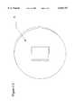
- FIG. 1Ais a front, partially disassembled, view of a preferred embodiment of the cut alignment device of this invention
- FIG. 1Bis a cross-sectional view of the device of FIG. 1A taken along line B--B;
- FIG. 1Cis a front view of the cover of the device of FIG. 1A;
- FIG. 1Dis a side view of the device of FIG. 1A;
- FIG. 2Ais a side view of a rotary saw carrying the device of FIG. 1A;
- FIG. 2Bis a front view of the saw of FIG. 2A.
- FIG. 3is a view similar to that of FIG. 1A of an alternative preferred embodiment of the invention.
- This inventionmay be accomplished in a cut alignment device for a rotary saw having a motor which spins a cutting unit.
- the term "cutting unit” as used hereinincludes a rotary shaft driven by the motor, a circular blade having a central aperture through which the shaft fits, and a blade mounting device for holding the blade on the shaft.
- the cut alignment device of the inventionincludes a battery power source with one or more batteries, carried by the cutting unit; and a beam light source, operatively connected to the power source, and also carried by the cutting unit. The result is a light beam which emanates from the cutting unit.
- the light sourceis arranged such that the beam intersects the material to be cut along the line along which the saw blade will cut (the cut line). Thus, the operator need only align the light line with a cutting mark in order for the cut to fall directly on the cutting mark.
- FIGS. 1 and 2A preferred embodiment of the cut alignment device of this invention is shown in FIGS. 1 and 2.
- Hollow annular housing 12 and removable annular cover 22 togetherare the same diameter and thickness as a typical lock washer which is part of the blade mounting device of rotary saws.
- the blade mounting device of rotary sawstypically includes a blade bolt 44, washer 46, and a lock washer, not shown (FIGS. 2A and 2B), which is replaced in this embodiment with housing 12 having cover 22.
- Bolt 44 and washer 46hold housing 12 against blade 30, so that blade 30 can be rotated by shaft 42, which is driven by motor 13.
- Housing 12is preferably made from cast aluminum. Housing 12 carries battery power source 16 comprising three, 1.2 volt hearing aid batteries interconnected by electrical lines 15. Housing 12 also carries laser diode assembly 14, which emits light in the range of 640 to 670 nm through aperture 26 in housing 12 to accomplish a beam light source. Assembly 14 comprises a laser diode 32, which may be a D6605 diode from NVG, Inc. of Hazlehurst, Ga., driven by diode driver circuit board 30, which may be an NS102, also from NVG. A focusing lens, not shown, such as an NVG. 4 from NVG, may be placed within aperture 26, or just inside or outside of the aperture to focus the light as necessary.
- battery power source 16comprising three, 1.2 volt hearing aid batteries interconnected by electrical lines 15.
- Housing 12also carries laser diode assembly 14, which emits light in the range of 640 to 670 nm through aperture 26 in housing 12 to accomplish a beam light source. Assembly 14 comprises a laser diode 32, which may
- Assembly 14 and/or this focusing lensis properly aligned such that the light beam emanating from aperture 26 strikes the material to be cut along the blade cut line. The exact alignment depends on the distance of aperture 26 from blade 30, and the distance between aperture 26 and the blade cutting edge.
- Centrifugally engaged motion activated switch 18is between power source 16 and laser diode assembly 14 so that laser diode assembly 14 is automatically powered only when housing 12 is spun by shaft 42.
- Electrical line 17connects centrifugally engaged motion activated switch 18 to power source 16, and line 19 provides power to assembly 14.
- FIG. 3An alternative embodiment is shown in FIG. 3. The only difference is that cylindrical laser module 40, which may be an MM6605 from NVG replaces diode 32, board 30, and the lens of FIG. 1 with a self-contained unit containing a diode, driver board and focusing lens.
- cylindrical laser module 40which may be an MM6605 from NVG replaces diode 32, board 30, and the lens of FIG. 1 with a self-contained unit containing a diode, driver board and focusing lens.
- This inventionis meant to encompass visible beam light sources other than laser diodes, for example incandescent lamps.
- Laser diodesare preferred because they are small enough to fit within the interior of a housing having a diameter of 40.8 mm, a thickness of 7.7 mm, and a wall thickness of about 1.5 mm, the dimensions of the preferred embodiment of housing 14 of this invention, yet are bright enough to cast a beam which appears on the material to be cut as a line once the light source is spun.
- Housing cover 22is preferably 1 mm thick
- This inventionis also meant to encompass a battery power source and beam light source carried anywhere on the cutting unit of a rotary saw. Since the cutting unit has a fixed, known relationship to the cutting blade, such will enable the light beam to intersect the material to be cut properly in the proper location--along the blade cut line. Thus, the battery and light source can be placed where desired on or in the rotary shaft, the blade, or the blade mounting device.
Landscapes
- Engineering & Computer Science (AREA)
- Mechanical Engineering (AREA)
- Life Sciences & Earth Sciences (AREA)
- Physics & Mathematics (AREA)
- Optics & Photonics (AREA)
- Wood Science & Technology (AREA)
- Forests & Forestry (AREA)
- Sawing (AREA)
Abstract
Description
This invention relates to a saw-mounted cut alignment device for a rotary saw which projects a line of light along the cut line.
Rotary saws such as circular saws, chop saws, radial arm saws, miter saws and table saws require that the operator properly align the material being cut with the saw blade. This takes time and care, but is critical for a proper cut.
There exist laser-based cut alignment devices which are externally mounted in the vicinity of the saw, and project a light beam along the cut line. These devices must be manually aligned before cutting begins, thus requiring experience and additional time. Also, the operator must monitor this additional piece of equipment in order to use the alignment device properly. Accordingly, devices of this nature are not practical for most saw owners and operators.
It is therefore an object of this invention to provide a cut alignment device for a rotary saw.
It is a further object of this invention to provide such a cut alignment device which is mounted to the saw.
It is a further object of this invention to provide such a cut alignment device which is automatically self-aligning with the blade cut line.
It is a further object of this invention to provide such a cut alignment device which requires no operator set-up.
It is a further object of this invention to provide such a cut alignment device which illuminates a straight line on the material to be cut along the blade cut line.
It is a further object of this invention to provide such a cut alignment device which turns on only when the saw is activated.
It is a further object of this invention to provide such a cut alignment device which decreases the amount of time required for a saw operator to align the material with the cutting edge of the saw blade.
This invention results from the realization that rotary saws can be made more accurate and easier to use with a light-source mounted on the rotating portion of the saw which projects a beam of light along the saw blade cutting line.
This invention features a cut alignment device for a rotary saw having a motor which spins a cutting unit which includes a rotary shaft driven by the motor, a circular blade having a central aperture through which the shaft fits, and a blade mounting device for holding the blade on the shaft, the cut alignment device comprising: a battery power source carried by the cutting unit; and a beam light source, operatively connected to said power source, and carried by the cutting unit; wherein said light source projects a light beam from the cutting unit directed along the cutting edge of the blade to assist the operator in cutting accurately.
The cut alignment device may further include a switch between said power source and said light source for selectively applying power to said light source. The switch may be centrifically engaged to automatically power said light source when the shaft is spinning. The light source may be mounted within the blade mounting device, and the blade mounting device may define an aperture from which the light beam emanates. The device may further include a focusing lens aligned with said aperture for focusing the light from said light source.
The blade mounting device may include a blade lock washer held on the shaft against the blade, and wherein said light source is mounted within said blade lock washer.
The battery power switch may be mounted within the blade mounting device.
Also featured is a cut alignment device for a rotary saw having a motor which spins a cutting unit which includes a rotary shaft driven by the motor, a circular blade having a central aperture through which the shaft fits, and a blade mounting device for holding the blade on the shaft, the cut alignment device comprising: a battery power source mounted within the blade lock washer; a light source operatively connected to said power source and mounted within the blade lock washer, wherein the blade lock washer defines an aperture from which the light emanates; and a centrifically-engaged switch between said power source and said light source and mounted within the blade lock washer to automatically power said light source when the shaft is spinning; wherein said light source projects a light beam from the aperture directed along the cutting edge of the blade to assist the operator in cutting accurately.
Other objects, features and advantages will occur to those skilled in the art from the following description of the preferred embodiments, and the accompanying drawings, in which:
FIG. 1A is a front, partially disassembled, view of a preferred embodiment of the cut alignment device of this invention;
FIG. 1B is a cross-sectional view of the device of FIG. 1A taken along line B--B;
FIG. 1C is a front view of the cover of the device of FIG. 1A;
FIG. 1D is a side view of the device of FIG. 1A;
FIG. 2A is a side view of a rotary saw carrying the device of FIG. 1A;
FIG. 2B is a front view of the saw of FIG. 2A; and
FIG. 3 is a view similar to that of FIG. 1A of an alternative preferred embodiment of the invention.
This invention may be accomplished in a cut alignment device for a rotary saw having a motor which spins a cutting unit. The term "cutting unit" as used herein includes a rotary shaft driven by the motor, a circular blade having a central aperture through which the shaft fits, and a blade mounting device for holding the blade on the shaft. The cut alignment device of the invention includes a battery power source with one or more batteries, carried by the cutting unit; and a beam light source, operatively connected to the power source, and also carried by the cutting unit. The result is a light beam which emanates from the cutting unit. The light source is arranged such that the beam intersects the material to be cut along the line along which the saw blade will cut (the cut line). Thus, the operator need only align the light line with a cutting mark in order for the cut to fall directly on the cutting mark.
A preferred embodiment of the cut alignment device of this invention is shown in FIGS. 1 and 2. Hollowannular housing 12 and removableannular cover 22 together are the same diameter and thickness as a typical lock washer which is part of the blade mounting device of rotary saws. The blade mounting device of rotary saws typically includes ablade bolt 44,washer 46, and a lock washer, not shown (FIGS. 2A and 2B), which is replaced in this embodiment withhousing 12 havingcover 22.Bolt 44 andwasher 46 holdhousing 12 againstblade 30, so thatblade 30 can be rotated byshaft 42, which is driven bymotor 13.
An alternative embodiment is shown in FIG. 3. The only difference is thatcylindrical laser module 40, which may be an MM6605 from NVG replacesdiode 32,board 30, and the lens of FIG. 1 with a self-contained unit containing a diode, driver board and focusing lens.
This invention is meant to encompass visible beam light sources other than laser diodes, for example incandescent lamps. Laser diodes are preferred because they are small enough to fit within the interior of a housing having a diameter of 40.8 mm, a thickness of 7.7 mm, and a wall thickness of about 1.5 mm, the dimensions of the preferred embodiment ofhousing 14 of this invention, yet are bright enough to cast a beam which appears on the material to be cut as a line once the light source is spun.Housing cover 22 is preferably 1 mm thick
This invention is also meant to encompass a battery power source and beam light source carried anywhere on the cutting unit of a rotary saw. Since the cutting unit has a fixed, known relationship to the cutting blade, such will enable the light beam to intersect the material to be cut properly in the proper location--along the blade cut line. Thus, the battery and light source can be placed where desired on or in the rotary shaft, the blade, or the blade mounting device.
Although specific features of the invention are shown in some drawings and not others, this is for convenience only, as each feature may be combined with any or all of the other features in accordance with the invention.
Other embodiments will occur to those skilled in the art and are within the following claims.
Claims (9)
1. A cut alignment device for a rotary saw having a motor which spins a cutting unit, said cutting unit including a rotary shaft driven by the motor, a circular blade having a central aperture through which the shaft fits, and a blade mounting device for holding the blade on the shaft, the cut alignment device comprising:
a battery power source carried by the cutting unit; and
a beam light source, operatively connected to said power source, and carried by the cutting unit;
wherein said light source projects a light beam from the cutting unit directed along the cutting edge of the blade to assist the operator in cutting accurately.
2. The cut alignment device of claim 1 further including a switch between said power source and said light source for selectively applying power to said light source.
3. The cut alignment device of claim 2 in which said switch is centrifically engaged to automatically power said light source when the shaft is spinning.
4. The cut alignment device of claim 1 in which said light source is mounted within the blade mounting device, and the blade mounting device defines an aperture from which the light beam emanates.
5. The cut alignment device of claim 4 further including a focusing lens aligned with said aperture for focusing the light from said light source.
6. The cut alignment device of claim 4 in which the blade mounting device includes a blade lock washer held on the shaft against the blade, and wherein said light source is mounted within said blade lock washer.
7. The cut alignment device of claim 1 in which said battery power source is mounted within the blade mounting device.
8. A cut alignment device for a rotary saw having a motor which spins a cutting unit, said cutting unit including a rotary shaft driven by the motor, a circular blade having a central aperture through which the shaft fits, and a blade mounting device for holding the blade on the shaft, the cut alignment device comprising:
a battery power source mounted within the blade mounting device;
a light source operatively connected to said power source and mounted within the blade mounting device, wherein the blade mounting device defines an aperture from which the light emanates; and
a centrifically-engaged switch between said power source and said light source and mounted within the blade mounting device to automatically power said light source when the shaft is spinning;
wherein said light source projects a light beam from the aperture directed along the cutting edge of the blade to assist the operator in cutting accurately.
9. The cut alignment device of claim 8 wherein said blade mounting device includes a lock washer, and said power source, light source, and switch are all located within said lock washer.
Priority Applications (5)
| Application Number | Priority Date | Filing Date | Title |
|---|---|---|---|
| US08/990,501US6035757A (en) | 1997-12-15 | 1997-12-15 | Rotary saw cut alignment device |
| PCT/US1998/026200WO1999030879A1 (en) | 1997-12-15 | 1998-12-09 | Rotary saw cut alignment device |
| AU17210/99AAU757119B2 (en) | 1997-12-15 | 1998-12-09 | Rotary saw cut alignment device |
| EP98962040AEP0966340A4 (en) | 1997-12-15 | 1998-12-09 | Rotary saw cut alignment device |
| CA 2284599CA2284599C (en) | 1997-12-15 | 1998-12-09 | Rotary saw cut alignment device |
Applications Claiming Priority (1)
| Application Number | Priority Date | Filing Date | Title |
|---|---|---|---|
| US08/990,501US6035757A (en) | 1997-12-15 | 1997-12-15 | Rotary saw cut alignment device |
Publications (1)
| Publication Number | Publication Date |
|---|---|
| US6035757Atrue US6035757A (en) | 2000-03-14 |
Family
ID=25536225
Family Applications (1)
| Application Number | Title | Priority Date | Filing Date |
|---|---|---|---|
| US08/990,501Expired - Fee RelatedUS6035757A (en) | 1997-12-15 | 1997-12-15 | Rotary saw cut alignment device |
Country Status (5)
| Country | Link |
|---|---|
| US (1) | US6035757A (en) |
| EP (1) | EP0966340A4 (en) |
| AU (1) | AU757119B2 (en) |
| CA (1) | CA2284599C (en) |
| WO (1) | WO1999030879A1 (en) |
Cited By (55)
| Publication number | Priority date | Publication date | Assignee | Title |
|---|---|---|---|---|
| US6203112B1 (en)* | 1999-05-03 | 2001-03-20 | American Standards Construction Corp. | Attachable road cutting apparatus |
| USD460469S1 (en) | 2001-05-09 | 2002-07-16 | One World Technologies, Inc. | Laser arbor |
| EP1258305A3 (en)* | 2001-05-18 | 2002-12-04 | Techtronic Industries Co., Ltd. | Miter saw having a light beam alignment system |
| US6497168B1 (en)* | 2000-10-06 | 2002-12-24 | Bernard I. Levine | Laser alignment system for saws with rotating blades |
| WO2003011538A1 (en)* | 2001-07-31 | 2003-02-13 | Caluori Raymond J | Angled light beam rotary saw cut alignment device |
| US20030140758A1 (en)* | 2002-01-25 | 2003-07-31 | One World Technologies Limited | Light beam alignment system |
| US20030202091A1 (en)* | 2002-04-18 | 2003-10-30 | Jaime Garcia | Modular assisted visualization system |
| US20030233921A1 (en)* | 2002-06-19 | 2003-12-25 | Garcia Jaime E. | Cutter with optical alignment system |
| US20040049927A1 (en)* | 2002-05-14 | 2004-03-18 | Chervon International Trading Co., Ltd. | Circular saw with laser alignment |
| USD492951S1 (en) | 2003-06-26 | 2004-07-13 | Raymond J. Caluori | Rotary saw cut alignment guide |
| US20040194600A1 (en)* | 2003-04-01 | 2004-10-07 | Chyi-Yiing Wu | Self-powered rotary optical aligning apparatus |
| US20040261592A1 (en)* | 1993-05-18 | 2004-12-30 | Rexon Industrial Corp., Ltd. | Laser guiding device for table saw machine |
| US20050094386A1 (en)* | 2003-10-10 | 2005-05-05 | Ross Zhang | Sawing direction positioning system for a bench saw |
| US6918331B2 (en)* | 2000-04-18 | 2005-07-19 | Makita Corporation | Lighted cutting tools |
| US20050160895A1 (en)* | 2002-10-31 | 2005-07-28 | Garcia Jaime E. | Dual bevel table saw |
| US20050166737A1 (en)* | 2002-07-29 | 2005-08-04 | Caluori Raymond J. | Positive-angled light beam rotary saw cut alignment device |
| US6937336B2 (en) | 2002-08-15 | 2005-08-30 | Black & Decker, Inc. | Optical alignment system for power tool |
| US20050188806A1 (en)* | 2002-10-31 | 2005-09-01 | Garcia Jaime E. | Riving knife assembly for a dual bevel table saw |
| US20050194366A1 (en)* | 2004-03-04 | 2005-09-08 | Chyi-Yiing Wu | Angle-variable optical marking apparatus |
| US20050199114A1 (en)* | 2004-03-11 | 2005-09-15 | Tzu-Feng Tseng | Cutting apparatus with alignment marker |
| US20050270531A1 (en)* | 2004-06-02 | 2005-12-08 | Garcia Jaime E | Optical alignment system for power tools |
| US20060076385A1 (en)* | 2002-04-18 | 2006-04-13 | Etter Mark A | Power tool control system |
| US20060075867A1 (en)* | 2002-11-27 | 2006-04-13 | Etter Mark A | Laser apparatus |
| US20060096425A1 (en)* | 2003-04-29 | 2006-05-11 | Keller David V | System and method for rapidly stopping a spinning table saw blade |
| US20060101958A1 (en)* | 2003-07-31 | 2006-05-18 | Garcia Jaime E | Table saw |
| US20060101961A1 (en)* | 2002-04-18 | 2006-05-18 | Etter Mark A | Power tool control system |
| US20060106482A1 (en)* | 2002-04-18 | 2006-05-18 | Etter Mark A | Power tool control system |
| US20060104731A1 (en)* | 2002-04-18 | 2006-05-18 | Etter Mark A | Drill press |
| US20060111809A1 (en)* | 2002-04-18 | 2006-05-25 | Etter Mark A | Graphical user interface |
| US20060116787A1 (en)* | 2002-04-18 | 2006-06-01 | Etter Mark A | Power tool control system |
| US7073268B1 (en) | 2002-04-18 | 2006-07-11 | Black & Decker Inc. | Level apparatus |
| EP1700660A1 (en)* | 2005-03-10 | 2006-09-13 | Metabowerke GmbH | Separating/milling device |
| US20060213347A1 (en)* | 2005-03-28 | 2006-09-28 | Der-Shyang Jan | Cutting line indicator |
| US20060277768A1 (en)* | 2005-04-29 | 2006-12-14 | Van Rijen Johannes G | Electric tool for shaping of an object |
| US20070017326A1 (en)* | 2005-07-20 | 2007-01-25 | One World Technologies Limited | Laser generator mounted on a fixed component of a handheld cutting device |
| US20070034065A1 (en)* | 2005-08-10 | 2007-02-15 | Rexon Industrial Corporation Ltd. | Laser marker for circular-saw machine |
| EP1759797A1 (en) | 2005-09-05 | 2007-03-07 | Quarton Inc. | Cutting line indicator |
| US20070107235A1 (en)* | 2005-11-15 | 2007-05-17 | Eastway Fair Company Limited Of Trident Chambers | Light assembly for circular saw |
| US7243440B2 (en) | 2004-10-06 | 2007-07-17 | Black & Decker Inc. | Gauge for use with power tools |
| CN1330447C (en)* | 2004-09-28 | 2007-08-08 | 邬贤波 | Hand saw capable of light guiding orientation cutting |
| US20070279913A1 (en)* | 2006-06-01 | 2007-12-06 | Kelly Robert R | Light beam redirecting apparatus |
| US20070289513A1 (en)* | 2006-06-16 | 2007-12-20 | Hsin-Chin Chen | Adjusting structure of a laser indicator of a sawing machine |
| CN100358659C (en)* | 2005-04-01 | 2008-01-02 | 方础光电科技股份有限公司 | Cutting Line Indicator |
| US20080017005A1 (en)* | 2006-07-18 | 2008-01-24 | Hsin-Chih Tung | Light path molding apparatus of cutting machine tool |
| US20080025014A1 (en)* | 2006-07-26 | 2008-01-31 | Hsin-Chin Chen | Adjusting structure of a laser indicator of a sawing machine |
| US20080034931A1 (en)* | 2006-08-10 | 2008-02-14 | Nash Derek J | Laser guide |
| CN100376369C (en)* | 2003-03-20 | 2008-03-26 | 日立工机株式会社 | Miter saw with light projection device |
| US20080105100A1 (en)* | 2006-11-08 | 2008-05-08 | Eastway Fair Company Limited | Adjustable laser module |
| US20080121082A1 (en)* | 2006-11-08 | 2008-05-29 | Eastway Fair Company Limited | Cutting device and laser module for use therewith |
| US20080137339A1 (en)* | 2006-12-06 | 2008-06-12 | Nash Derek J | Laser guide |
| US20080220912A1 (en)* | 2007-02-23 | 2008-09-11 | Hawk-Eye Sensors Limited | System and method of preparing a playing surface |
| US8359960B2 (en) | 1999-02-05 | 2013-01-29 | Hitachi Koki Co., Ltd. | Cutter with laser generator that irradiates cutting position on workpiece to facilitate alignment of blade with cutting position |
| US9162298B2 (en) | 2013-03-07 | 2015-10-20 | Rexon Industrial Corp., Ltd. | Laser alignment device for circular saw |
| US20220055667A1 (en)* | 2018-11-12 | 2022-02-24 | Eiffage Metal | Device for controlling the embarking in a cable transport facility |
| US20220266471A1 (en)* | 2021-02-11 | 2022-08-25 | Whetter's Wood Products Llc | Cutting Guide |
Families Citing this family (1)
| Publication number | Priority date | Publication date | Assignee | Title |
|---|---|---|---|---|
| GB2408482A (en)* | 2003-11-27 | 2005-06-01 | Qingdao D&D Electro Mechanical Technologies Co Ltd | Sawing direction positioning system for a bench saw |
Citations (7)
| Publication number | Priority date | Publication date | Assignee | Title |
|---|---|---|---|---|
| US4335510A (en)* | 1980-06-18 | 1982-06-22 | Black & Decker, Inc. | String trimmer |
| US4503740A (en)* | 1982-01-18 | 1985-03-12 | Capital Machine Company, Inc. | Optical cutting edge locator for a cutting apparatus |
| US4833782A (en)* | 1987-06-01 | 1989-05-30 | Robert E. Strauss | Saber saw tracing light |
| US5060384A (en)* | 1990-12-06 | 1991-10-29 | Inertia Dynamics Corporation | Automatic head for a line trimmer |
| US5285708A (en)* | 1992-05-18 | 1994-02-15 | Porter-Cable Corporation | Miter saw alignment system |
| US5446635A (en)* | 1993-06-24 | 1995-08-29 | Quarton, Inc. | Laser assembly for marking a line on a workpiece for guiding a cutting tool |
| US5630277A (en)* | 1994-08-18 | 1997-05-20 | Kabushiki Kaisha Ogura | Portable, power driven punching machine having an aiming beam |
Family Cites Families (5)
| Publication number | Priority date | Publication date | Assignee | Title |
|---|---|---|---|---|
| US4257297A (en)* | 1979-01-31 | 1981-03-24 | Peter Nidbella | Circular saw with visual cut line indicator |
| FI64760C (en)* | 1981-05-29 | 1984-01-10 | Ahlstroem Oy | FOERFARANDE FOER INRIKTNING AV EN STOCK |
| US4885967A (en)* | 1988-08-25 | 1989-12-12 | J. Gibson Mcilvain Company | Laser alignment device for sawmills |
| US5199343A (en)* | 1991-10-09 | 1993-04-06 | Black & Decker Inc. | Power saw with louvered blade guard |
| US5675899A (en)* | 1996-05-28 | 1997-10-14 | Webb; James | Rotary saw with laser beam alignment |
- 1997
- 1997-12-15USUS08/990,501patent/US6035757A/ennot_activeExpired - Fee Related
- 1998
- 1998-12-09AUAU17210/99Apatent/AU757119B2/ennot_activeCeased
- 1998-12-09WOPCT/US1998/026200patent/WO1999030879A1/enactiveIP Right Grant
- 1998-12-09CACA 2284599patent/CA2284599C/ennot_activeExpired - Fee Related
- 1998-12-09EPEP98962040Apatent/EP0966340A4/ennot_activeWithdrawn
Patent Citations (7)
| Publication number | Priority date | Publication date | Assignee | Title |
|---|---|---|---|---|
| US4335510A (en)* | 1980-06-18 | 1982-06-22 | Black & Decker, Inc. | String trimmer |
| US4503740A (en)* | 1982-01-18 | 1985-03-12 | Capital Machine Company, Inc. | Optical cutting edge locator for a cutting apparatus |
| US4833782A (en)* | 1987-06-01 | 1989-05-30 | Robert E. Strauss | Saber saw tracing light |
| US5060384A (en)* | 1990-12-06 | 1991-10-29 | Inertia Dynamics Corporation | Automatic head for a line trimmer |
| US5285708A (en)* | 1992-05-18 | 1994-02-15 | Porter-Cable Corporation | Miter saw alignment system |
| US5446635A (en)* | 1993-06-24 | 1995-08-29 | Quarton, Inc. | Laser assembly for marking a line on a workpiece for guiding a cutting tool |
| US5630277A (en)* | 1994-08-18 | 1997-05-20 | Kabushiki Kaisha Ogura | Portable, power driven punching machine having an aiming beam |
Non-Patent Citations (2)
| Title |
|---|
| Northern Hydraulics Catalog, Inc, Mail order catalog "Northern", p. 37, right column, Item A, Flyer #701 (1-800-533-5545), Dec., 1998. |
| Northern Hydraulics Catalog, Inc, Mail order catalog Northern , p. 37, right column, Item A, Flyer 701 (1 800 533 5545), Dec., 1998.* |
Cited By (89)
| Publication number | Priority date | Publication date | Assignee | Title |
|---|---|---|---|---|
| US20040261592A1 (en)* | 1993-05-18 | 2004-12-30 | Rexon Industrial Corp., Ltd. | Laser guiding device for table saw machine |
| US8770076B2 (en) | 1999-02-05 | 2014-07-08 | Hitachi Koki Co., Ltd. | Cutter with laser generator that irradiates cutting position on workpiece to facilitate alignment of blade with cutting position |
| US8359960B2 (en) | 1999-02-05 | 2013-01-29 | Hitachi Koki Co., Ltd. | Cutter with laser generator that irradiates cutting position on workpiece to facilitate alignment of blade with cutting position |
| US6203112B1 (en)* | 1999-05-03 | 2001-03-20 | American Standards Construction Corp. | Attachable road cutting apparatus |
| US6918331B2 (en)* | 2000-04-18 | 2005-07-19 | Makita Corporation | Lighted cutting tools |
| US6497168B1 (en)* | 2000-10-06 | 2002-12-24 | Bernard I. Levine | Laser alignment system for saws with rotating blades |
| USD460469S1 (en) | 2001-05-09 | 2002-07-16 | One World Technologies, Inc. | Laser arbor |
| EP1470883A3 (en)* | 2001-05-18 | 2005-03-09 | Techtronic Industries Co., Ltd. | Miter saw having a light beam alignment system |
| US20050217445A1 (en)* | 2001-05-18 | 2005-10-06 | One World Technologies Limited | Miter saw having a light beam alignment system |
| US7398719B2 (en) | 2001-05-18 | 2008-07-15 | Eastway Fair Company Limited | Miter saw having a light beam alignment system |
| US6755107B2 (en)* | 2001-05-18 | 2004-06-29 | One World Technologies Lmt. | Miter saw having a light beam alignment system |
| CN1301186C (en)* | 2001-05-18 | 2007-02-21 | 创科实业有限公司 | A miter saw with a beam alignment system |
| US20040159199A1 (en)* | 2001-05-18 | 2004-08-19 | One World Technologies Limited | Miter saw having a light beam alignment system |
| EP1258305A3 (en)* | 2001-05-18 | 2002-12-04 | Techtronic Industries Co., Ltd. | Miter saw having a light beam alignment system |
| US6915727B2 (en) | 2001-07-31 | 2005-07-12 | Raymond Caluori | Angled light beam rotary saw cut alignment device |
| WO2003011538A1 (en)* | 2001-07-31 | 2003-02-13 | Caluori Raymond J | Angled light beam rotary saw cut alignment device |
| US7159497B2 (en)* | 2002-01-25 | 2007-01-09 | Eastway Fair Company Ltd. | Light beam alignment system |
| AU785142B2 (en)* | 2002-01-25 | 2006-10-05 | Techtronic Industries Co., Ltd. | Light beam alignment system |
| US20030140758A1 (en)* | 2002-01-25 | 2003-07-31 | One World Technologies Limited | Light beam alignment system |
| EP1331055A3 (en)* | 2002-01-25 | 2003-08-20 | Techtronic Industries Co., Ltd. | Light beam alignment system |
| US20070107573A1 (en)* | 2002-01-25 | 2007-05-17 | Eastway Fair Company Limited Of Trident Chambers | Light beam alignment system |
| CN100519029C (en)* | 2002-01-25 | 2009-07-29 | 创科实业有限公司 | Light beam alignment system |
| US7346847B2 (en) | 2002-04-18 | 2008-03-18 | Black & Decker Inc. | Power tool control system user interface |
| US20060106482A1 (en)* | 2002-04-18 | 2006-05-18 | Etter Mark A | Power tool control system |
| US20030202091A1 (en)* | 2002-04-18 | 2003-10-30 | Jaime Garcia | Modular assisted visualization system |
| US7073268B1 (en) | 2002-04-18 | 2006-07-11 | Black & Decker Inc. | Level apparatus |
| US20060116787A1 (en)* | 2002-04-18 | 2006-06-01 | Etter Mark A | Power tool control system |
| US7369916B2 (en) | 2002-04-18 | 2008-05-06 | Black & Decker Inc. | Drill press |
| US20060076385A1 (en)* | 2002-04-18 | 2006-04-13 | Etter Mark A | Power tool control system |
| US7359762B2 (en) | 2002-04-18 | 2008-04-15 | Black & Decker Inc. | Measurement and alignment device including a display system |
| US8004664B2 (en) | 2002-04-18 | 2011-08-23 | Chang Type Industrial Company | Power tool control system |
| US20060111809A1 (en)* | 2002-04-18 | 2006-05-25 | Etter Mark A | Graphical user interface |
| US20060104731A1 (en)* | 2002-04-18 | 2006-05-18 | Etter Mark A | Drill press |
| US20060101961A1 (en)* | 2002-04-18 | 2006-05-18 | Etter Mark A | Power tool control system |
| US20060102682A1 (en)* | 2002-04-18 | 2006-05-18 | Etter Mark A | Power tool control system user interface |
| US20040049927A1 (en)* | 2002-05-14 | 2004-03-18 | Chervon International Trading Co., Ltd. | Circular saw with laser alignment |
| US20060101969A1 (en)* | 2002-06-19 | 2006-05-18 | Garcia Jaime E | Optical alignment system |
| US20050126356A1 (en)* | 2002-06-19 | 2005-06-16 | Delta International Machinery Corp. | Cutter with optical alignment system |
| US7926398B2 (en) | 2002-06-19 | 2011-04-19 | Black & Decker Inc. | Cutter with optical alignment system |
| US20030233921A1 (en)* | 2002-06-19 | 2003-12-25 | Garcia Jaime E. | Cutter with optical alignment system |
| US7836806B2 (en)* | 2002-07-29 | 2010-11-23 | Caluori Raymond J | Positive-angled light beam rotary saw cut alignment device |
| US20050166737A1 (en)* | 2002-07-29 | 2005-08-04 | Caluori Raymond J. | Positive-angled light beam rotary saw cut alignment device |
| US6937336B2 (en) | 2002-08-15 | 2005-08-30 | Black & Decker, Inc. | Optical alignment system for power tool |
| US20050160895A1 (en)* | 2002-10-31 | 2005-07-28 | Garcia Jaime E. | Dual bevel table saw |
| US7137327B2 (en) | 2002-10-31 | 2006-11-21 | Black & Decker Inc. | Riving knife assembly for a dual bevel table saw |
| US20050188806A1 (en)* | 2002-10-31 | 2005-09-01 | Garcia Jaime E. | Riving knife assembly for a dual bevel table saw |
| US20060075867A1 (en)* | 2002-11-27 | 2006-04-13 | Etter Mark A | Laser apparatus |
| CN100376369C (en)* | 2003-03-20 | 2008-03-26 | 日立工机株式会社 | Miter saw with light projection device |
| US20040194600A1 (en)* | 2003-04-01 | 2004-10-07 | Chyi-Yiing Wu | Self-powered rotary optical aligning apparatus |
| US7168180B2 (en)* | 2003-04-01 | 2007-01-30 | Chyi-Yiing Wu | Self-powered rotary optical aligning apparatus |
| US20060096425A1 (en)* | 2003-04-29 | 2006-05-11 | Keller David V | System and method for rapidly stopping a spinning table saw blade |
| US7290474B2 (en) | 2003-04-29 | 2007-11-06 | Black & Decker Inc. | System for rapidly stopping a spinning table saw blade |
| USD492951S1 (en) | 2003-06-26 | 2004-07-13 | Raymond J. Caluori | Rotary saw cut alignment guide |
| US20060101958A1 (en)* | 2003-07-31 | 2006-05-18 | Garcia Jaime E | Table saw |
| US20050094386A1 (en)* | 2003-10-10 | 2005-05-05 | Ross Zhang | Sawing direction positioning system for a bench saw |
| US20050194366A1 (en)* | 2004-03-04 | 2005-09-08 | Chyi-Yiing Wu | Angle-variable optical marking apparatus |
| US7135654B2 (en)* | 2004-03-04 | 2006-11-14 | Chyi-Yiing Wu | Angle-variable optical marking apparatus |
| US20050199114A1 (en)* | 2004-03-11 | 2005-09-15 | Tzu-Feng Tseng | Cutting apparatus with alignment marker |
| US20050270531A1 (en)* | 2004-06-02 | 2005-12-08 | Garcia Jaime E | Optical alignment system for power tools |
| CN1330447C (en)* | 2004-09-28 | 2007-08-08 | 邬贤波 | Hand saw capable of light guiding orientation cutting |
| US20070295777A1 (en)* | 2004-10-06 | 2007-12-27 | Black & Decker Inc. | Gauge for use with power tools |
| US7243440B2 (en) | 2004-10-06 | 2007-07-17 | Black & Decker Inc. | Gauge for use with power tools |
| US7658501B2 (en) | 2005-03-10 | 2010-02-09 | Metabowerke Gmbh | Cutoff/milling device |
| US20060203469A1 (en)* | 2005-03-10 | 2006-09-14 | Metabowerke Gmbh | Cutoff/milling device |
| EP1700660A1 (en)* | 2005-03-10 | 2006-09-13 | Metabowerke GmbH | Separating/milling device |
| US20060213347A1 (en)* | 2005-03-28 | 2006-09-28 | Der-Shyang Jan | Cutting line indicator |
| CN100358659C (en)* | 2005-04-01 | 2008-01-02 | 方础光电科技股份有限公司 | Cutting Line Indicator |
| US20060277768A1 (en)* | 2005-04-29 | 2006-12-14 | Van Rijen Johannes G | Electric tool for shaping of an object |
| US20070017326A1 (en)* | 2005-07-20 | 2007-01-25 | One World Technologies Limited | Laser generator mounted on a fixed component of a handheld cutting device |
| US20070034065A1 (en)* | 2005-08-10 | 2007-02-15 | Rexon Industrial Corporation Ltd. | Laser marker for circular-saw machine |
| EP1759797A1 (en) | 2005-09-05 | 2007-03-07 | Quarton Inc. | Cutting line indicator |
| US20070107235A1 (en)* | 2005-11-15 | 2007-05-17 | Eastway Fair Company Limited Of Trident Chambers | Light assembly for circular saw |
| US20070279913A1 (en)* | 2006-06-01 | 2007-12-06 | Kelly Robert R | Light beam redirecting apparatus |
| US20070289513A1 (en)* | 2006-06-16 | 2007-12-20 | Hsin-Chin Chen | Adjusting structure of a laser indicator of a sawing machine |
| US20080017005A1 (en)* | 2006-07-18 | 2008-01-24 | Hsin-Chih Tung | Light path molding apparatus of cutting machine tool |
| US20080025014A1 (en)* | 2006-07-26 | 2008-01-31 | Hsin-Chin Chen | Adjusting structure of a laser indicator of a sawing machine |
| US20080034931A1 (en)* | 2006-08-10 | 2008-02-14 | Nash Derek J | Laser guide |
| US20080121082A1 (en)* | 2006-11-08 | 2008-05-29 | Eastway Fair Company Limited | Cutting device and laser module for use therewith |
| US20080105100A1 (en)* | 2006-11-08 | 2008-05-08 | Eastway Fair Company Limited | Adjustable laser module |
| US7556401B2 (en) | 2006-11-08 | 2009-07-07 | Eastway Fair Company Limited | Adjustable laser module |
| US20080137339A1 (en)* | 2006-12-06 | 2008-06-12 | Nash Derek J | Laser guide |
| US7966738B2 (en) | 2006-12-06 | 2011-06-28 | Irwin Industrial Tool Company | Laser guide |
| US20080220912A1 (en)* | 2007-02-23 | 2008-09-11 | Hawk-Eye Sensors Limited | System and method of preparing a playing surface |
| US7846046B2 (en)* | 2007-02-23 | 2010-12-07 | Hawk-Eye Sensors Limited | System and method of preparing a playing surface |
| US9162298B2 (en) | 2013-03-07 | 2015-10-20 | Rexon Industrial Corp., Ltd. | Laser alignment device for circular saw |
| US20220055667A1 (en)* | 2018-11-12 | 2022-02-24 | Eiffage Metal | Device for controlling the embarking in a cable transport facility |
| US12403939B2 (en)* | 2018-11-12 | 2025-09-02 | Poma | Device for controlling the embarking in a cable transport facility |
| US20220266471A1 (en)* | 2021-02-11 | 2022-08-25 | Whetter's Wood Products Llc | Cutting Guide |
| US11752655B2 (en)* | 2021-02-11 | 2023-09-12 | Whetter's Wood Products Llc | Cutting guide |
Also Published As
| Publication number | Publication date |
|---|---|
| EP0966340A4 (en) | 2005-09-07 |
| CA2284599A1 (en) | 1999-06-24 |
| AU757119B2 (en) | 2003-02-06 |
| CA2284599C (en) | 2004-03-30 |
| WO1999030879A1 (en) | 1999-06-24 |
| EP0966340A1 (en) | 1999-12-29 |
| AU1721099A (en) | 1999-07-05 |
Similar Documents
| Publication | Publication Date | Title |
|---|---|---|
| US6035757A (en) | Rotary saw cut alignment device | |
| US5862727A (en) | Laser arbor | |
| US7159497B2 (en) | Light beam alignment system | |
| US7568288B2 (en) | Power hand tool right angle attachment having a light source with a self-generating power supply | |
| US6584695B1 (en) | Laser alignment device of a circular saw | |
| US6915727B2 (en) | Angled light beam rotary saw cut alignment device | |
| US5461790A (en) | Circular saws with laser guides for more precise movement during cutting | |
| US7398719B2 (en) | Miter saw having a light beam alignment system | |
| JP3291732B2 (en) | Indicating instrument | |
| US20040194600A1 (en) | Self-powered rotary optical aligning apparatus | |
| DK0633830T4 (en) | Mounting hub for saw blades | |
| US4498868A (en) | Dental hand piece | |
| US7836806B2 (en) | Positive-angled light beam rotary saw cut alignment device | |
| US2906304A (en) | Saber saw | |
| US20050098011A1 (en) | Circular saw with a sawing path indicating device | |
| US20050011325A1 (en) | Light beam rotary saw cut alignment device | |
| WO2008133317A1 (en) | Electric tool | |
| AU2020274440A1 (en) | Portable machine tool | |
| WO2007139575A1 (en) | Light beam redirecting apparatus | |
| JPH04251704A (en) | Boring tool | |
| JP2002046084A (en) | Laser equipment for power tool ink marking | |
| KR950005454A (en) | Illumination of Vision System Tool Wear Monitoring System Using Light Emithed Diode |
Legal Events
| Date | Code | Title | Description |
|---|---|---|---|
| FPAY | Fee payment | Year of fee payment:4 | |
| RR | Request for reexamination filed | Effective date:20060821 | |
| RR | Request for reexamination filed | Effective date:20060821 | |
| FPAY | Fee payment | Year of fee payment:8 | |
| FPB1 | Reexamination decision cancelled all claims | ||
| FEPP | Fee payment procedure | Free format text:PAYOR NUMBER ASSIGNED (ORIGINAL EVENT CODE: ASPN); ENTITY STATUS OF PATENT OWNER: SMALL ENTITY | |
| REMI | Maintenance fee reminder mailed | ||
| LAPS | Lapse for failure to pay maintenance fees | ||
| STCH | Information on status: patent discontinuation | Free format text:PATENT EXPIRED DUE TO NONPAYMENT OF MAINTENANCE FEES UNDER 37 CFR 1.362 | |
| FP | Lapsed due to failure to pay maintenance fee | Effective date:20120314 |