US6035266A - Lamp monitoring and control system and method - Google Patents
Lamp monitoring and control system and methodDownload PDFInfo
- Publication number
- US6035266A US6035266AUS08/838,303US83830397AUS6035266AUS 6035266 AUS6035266 AUS 6035266AUS 83830397 AUS83830397 AUS 83830397AUS 6035266 AUS6035266 AUS 6035266A
- Authority
- US
- United States
- Prior art keywords
- monitoring
- lamp
- data
- lamps
- status
- Prior art date
- Legal status (The legal status is an assumption and is not a legal conclusion. Google has not performed a legal analysis and makes no representation as to the accuracy of the status listed.)
- Expired - Lifetime
Links
Images


Classifications
- H—ELECTRICITY
- H05—ELECTRIC TECHNIQUES NOT OTHERWISE PROVIDED FOR
- H05B—ELECTRIC HEATING; ELECTRIC LIGHT SOURCES NOT OTHERWISE PROVIDED FOR; CIRCUIT ARRANGEMENTS FOR ELECTRIC LIGHT SOURCES, IN GENERAL
- H05B47/00—Circuit arrangements for operating light sources in general, i.e. where the type of light source is not relevant
- H05B47/20—Responsive to malfunctions or to light source life; for protection
- H05B47/21—Responsive to malfunctions or to light source life; for protection of two or more light sources connected in parallel
- H05B47/22—Responsive to malfunctions or to light source life; for protection of two or more light sources connected in parallel with communication between the lamps and a central unit
- H—ELECTRICITY
- H05—ELECTRIC TECHNIQUES NOT OTHERWISE PROVIDED FOR
- H05B—ELECTRIC HEATING; ELECTRIC LIGHT SOURCES NOT OTHERWISE PROVIDED FOR; CIRCUIT ARRANGEMENTS FOR ELECTRIC LIGHT SOURCES, IN GENERAL
- H05B47/00—Circuit arrangements for operating light sources in general, i.e. where the type of light source is not relevant
- H05B47/10—Controlling the light source
- H05B47/175—Controlling the light source by remote control
- H05B47/198—Grouping of control procedures or address assignation to light sources
- H—ELECTRICITY
- H05—ELECTRIC TECHNIQUES NOT OTHERWISE PROVIDED FOR
- H05B—ELECTRIC HEATING; ELECTRIC LIGHT SOURCES NOT OTHERWISE PROVIDED FOR; CIRCUIT ARRANGEMENTS FOR ELECTRIC LIGHT SOURCES, IN GENERAL
- H05B47/00—Circuit arrangements for operating light sources in general, i.e. where the type of light source is not relevant
- H05B47/10—Controlling the light source
- H05B47/175—Controlling the light source by remote control
- H05B47/19—Controlling the light source by remote control via wireless transmission
Definitions
- This inventionrelates generally to a system and method for remotely monitoring and/or controlling an apparatus and specifically to a lamp monitoring and control system and method for use with street lamps.
- the present inventionincludes a monitoring and control unit, such as the lamp monitoring and control unit disclosed in co-pending application entitled “LAMP MONITORING AND CONTROL UNIT AND METHOD", Ser. No. 08/838,302, the contents of which are incorporated herein by reference.
- the first street lampswere used in Europe during the latter half of the seventeenth century. These lamps consisted of lanterns which were attached to cables strung across the street so that the lantern hung over the center of the street. In France, the police were responsible for operating and maintaining these original street lamps while in England contractors were hired for street lamp operation and maintenance. In all instances, the operation and maintenance of street lamps was considered a government function.
- monitor and controlThe operation and maintenance of street lamps, or more generally any units which are distributed over a large geographic area, can be divided into two tasks: monitor and control. Monitoring comprises the transmission of information from the distributed unit regarding the unit's status and controlling comprises the reception of information by the distributed unit.
- the monitoring functioncomprises periodic checks of the street lamps to determine if they are functioning properly.
- the controlling functioncomprises turning the street lamps on at night and off during the day.
- the early electrical street lampswere composed of arc lamps in which the illumination was produced by an arc of electricity flowing between two electrodes.
- the mercury-vapor lampis the most common form of street lamp in use today. In this type of lamp, the illumination is produced by an arc which takes place in a mercury vapor.
- FIG. 1shows the configuration of a typical mercury-vapor lamp. This figure is provided only for demonstration purposes since there are a variety of different types of mercury-vapor lamps.
- the mercury-vapor lampconsists of an arc tube 110 which is filled with argon gas and a small amount of pure mercury.
- Arc tube 110is mounted inside a large outer bulb 120 which encloses and protects the arc tube. Additionally, the outer bulb may be coated with phosphors to improve the color of the light emitted and reduce the ultraviolet radiation emitted.
- Mounting of arc tube 110 inside outer bulb 120may be accomplished with an arc tube mount support 130 on the top and a stem 140 on the bottom.
- Main electrodes 150a and 150bare mechanically sealed at both ends of arc tube 110.
- the mercury-vapor lamprequires a sizeable voltage to start the arc between main electrodes 150a and 150b.
- the starting of the mercury-vapor lampis controlled by a starting circuit (not shown in FIG. 1) which is attached between the power source (not shown in FIG. 1) and the lamp.
- a starting circuit(not shown in FIG. 1) which is attached between the power source (not shown in FIG. 1) and the lamp.
- the lamp currentwill continue to increase unless the starting circuit provides some means for limiting the current.
- the lamp currentis limited by a resistor, which severely reduces the efficiency of the circuit, or by a magnetic device, such as a choke or a transformer, called a ballast.
- the mercury-vapor lampmay require minutes of warm-up before light is emitted. Additionally, if power is lost, the lamp must cool and the mercury pressure must decrease before the starting arc can start again.
- the mercury-vapor lamphas become one of the predominant types of street lamp with millions of units produced annually.
- the current installed base of these street lampsis enormous with more than 500,000 street lamps in Los Angeles alone.
- the mercury-vapor lampis not the most efficient gaseous discharge lamp, but is preferred for use in street lamps because of its long life, reliable performance, and relatively low cost.
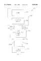
- FIG. 2shows a lamp arrangement 201 with a typical lamp sensor unit 210 which is situated between a power source 220 and a lamp assembly 230.
- Lamp assembly 230includes a lamp 240 (such as the mercury-vapor lamp presented in FIG. 1) and a starting circuit 250.
- a typical street lamp assembly 201includes a lamp sensor unit 210 which in turn includes a light sensor 260 and a relay 270 as shown in FIG. 2.
- Lamp sensor unit 210is electrically coupled between external power source 220 and starting circuit 250 of lamp assembly 230.
- there is a switched line 280c and a neutral line 280dproviding electrical connection between lamp sensor unit 210 and starting circuit 250 of lamp assembly 230.
- lamp sensor units 210use a standard three prong plug, for example a twist lock plug, to connect to the back of lamp assembly 230.
- the three prongscouple to hot line 280a, switched line 280c, and neutral lines 280b and 280d.
- the neutral lines 280b and 280dare both connected to the same physical prong since they are at the same electrical potential.
- Some systemsalso have a ground wire, but no ground wire is shown in FIG. 2 since it is not relevant to the operation of lamp sensor unit 210.
- Power source 220may be a standard 115 Volt, 60 Hz source from a power line. Of course, a variety of alternatives are available for power source 220. In foreign countries, power source 220 may be a 220 Volt, 50 Hz source from a power line. Additionally, power source 220 may be a DC voltage source or, in certain remote regions, it may be a battery which is charged by a solar reflector.
- lamp sensor unit 210The operation of lamp sensor unit 210 is fairly simple. At sunset, when the light from the sun decreases below a sunset threshold, light sensor 260 detects this condition and causes relay 270 to close. Closure of relay 270 results in electrical connection of hot line 280a and switched line 280c with power being applied to starting circuit 250 of lamp assembly 230 to ultimately produce light from lamp 240. At sunrise, when the light from the sun increases above a sunrise threshold, light sensor 260 detects this condition and causes relay 270 to open. Opening of relay 270 eliminates electrical connection between hot line 280a and switched line 280c and causes the removal of power from starting circuit 250 which turns lamp 240 off.
- Lamp sensor unit 210provides an automated, distributed control mechanism to turn lamp assembly 230 on and off. Unfortunately, it provides no mechanism for centralized monitoring of the street lamp to determine if the lamp is functioning properly. This problem is particularly important in regard to the street lamps on major boulevards and highways in large cities. When a street lamp burns out over a highway, it is often not replaced for a long period of time because the maintenance crew will only schedule a replacement lamp when someone calls the city maintenance department and identifies the exact pole location of the bad lamp. Since most automobile drivers will not stop on the highway just to report a bad street lamp, a bad lamp may go unreported indefinitely.
- hidden problemsrelate to current, when the lamp is drawing significantly more current than is normal, or voltage, when the power supply is not supplying the appropriate voltage level to the street lamp.
- the present system of lamp control in which an individual light sensor is located at each street lampis a distributed control system which does not allow for centralized control. For example, if the city wanted to turn on all of the street lamps in a certain area at a certain time, this could not be done because of the distributed nature of the present lamp control circuits.
- the RadioSwitchSince the RadioSwitch is receive only (no transmit capability), it only allows one to remotely control external equipment. Furthermore, since the communication link for the RadioSwitch is via paging networks, it is unable to operate in areas in which paging does not exist (for example, large rural areas in the United States). Additionally, although the RadioSwitch can be used to control street lamps, it does not use the standard three prong interface used by the present lamp control units. Accordingly, installation is difficult because it cannot be used as a plug-in replacement for the current lamp control units.
- the present inventionprovides a lamp monitoring and control system and method for use with street lamps which solves the problems described above.
- an object of the present inventionis to provide a system for monitoring and controlling lamps or any remote device over a large geographical area.
- Another object of the inventionis to provide a method for randomizing transmit times and channel numbers to reduce the probability of a packet collision.
- An additional object of the present inventionis to provide a base station for receiving monitoring data from remote devices.
- Another object of the current inventionis to provide an ID and status processing unit in the base station for processing an ID and status field in the monitoring data and allowing storage in a database to create statistical profiles.
- An advantage of the present inventionis that it solves the problem of efficiently providing centralized monitoring and/or control of the street lamps in a geographical area.
- Another advantage of the present inventionis that by randomizing the frequency and timing of redundant transmissions, it reduces the probability of collisions while increasing the probability of a successful packet reception.
- An additional advantage of the present inventionis that it provides for a new type of monitoring and control unit which allows centralized monitoring and/or control of units distributed over a large geographical area.
- Another advantage of the present inventionis that it allows bases stations to be connected to other base stations or to a main station in a network topology to increase the amount of monitoring data in the overall system.
- a feature of the present inventionin accordance with one embodiment, is that it includes the base station with an ID and status processing unit for processing the ID field of the monitoring data.
- the monitoring datafurther includes a data field which can store current or voltage data in a lamp monitoring and control system.
- An additional feature of the present inventionin accordance with another embodiment, is that it includes remote device monitoring and control units which can be linked to the bases station via RF, wire, coaxial cable, or fiber optics.
- a lamp monitoring and control systemcomprising lamp monitoring and control units, each coupled to a respective lamp to monitor and control, and each transmitting monitoring data having at least an ID field and a status field; and at least one base station, coupled to a group of the lamp monitoring and control units, for receiving the monitoring data, wherein each of the base stations includes an ID and status processing unit for processing the ID field of the monitoring data.
- a remote device monitoring and control systemcomprising remote device monitoring and control units, each coupled to a respective remote device to monitor and control, and each transmitting monitoring data having at least an ID field and a status field; and at least one base station, coupled to a group of the remote device monitoring and control units, for receiving the monitoring data, wherein each of the base stations includes an ID and status processing unit for processing the ID field of the monitoring data.
- FIG. 1shows the configuration of a typical mercury-vapor lamp.
- FIG. 2shows a typical configuration of a lamp arrangement comprising a lamp sensor unit situated between a power source and a lamp assembly.
- FIG. 3shows a lamp arrangement, according to one embodiment of the invention, comprising a lamp monitoring and control unit situated between a power source and a lamp assembly.
- FIG. 4shows a lamp monitoring and control unit, according to another embodiment of the invention, including a processing and sensing unit, a TX unit, and an RX unit.
- FIG. 5shows a general monitoring and control unit, according to another embodiment of the invention, including a processing and sensing unit, a TX unit, and an RX unit.
- FIG. 6shows a monitoring and control system, according to another embodiment of the invention, including a base station and a plurality of monitoring and control units.
- FIG. 7shows a monitoring and control system, according to another embodiment of the invention, including a plurality of base stations, each having a plurality of associated monitoring and control units.
- FIG. 8shows an example frequency channel plan for a monitoring and control system, according to another embodiment of the invention.
- FIGS. 9A-Bshow packet formats, according to another embodiment of the invention, for packet data between the monitoring and control unit and the base station.
- FIG. 10shows an example of bit location values for a status byte in the packet format, according to another embodiment of the invention.
- FIGS. 11A-Cshow a base station for use in a monitoring and control system, according to another embodiment of the invention.
- FIG. 12shows a monitoring and control system, according to another embodiment of the invention, having a main station coupled through a plurality of communication links to a plurality of base stations.
- FIG. 13shows a base station, according to another embodiment of the invention.
- FIGS. 14A-Eshow a method for one implementation of logic for a monitoring and control system, according to another embodiment of the invention.
- LMCSlamp monitoring and control system
- methodwhich allows centralized monitoring and/or control of street lamps.
- LMCSlamp monitoring and control system
- street lampin this disclosure is used in a general sense to describe any type of street lamp, area lamp, or outdoor lamp.
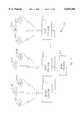
- FIG. 3shows a lamp arrangement 301 which includes lamp monitoring and control unit 310, according to one embodiment of the invention.
- Lamp monitoring and control unit 310is situated between a power source 220 and a lamp assembly 230.
- Lamp assembly 230includes a lamp 240 and a starting circuit 250.
- Power source 220may be a standard 115 volt, 60 Hz source supplied by a power line. It is well known to those skilled in the art that a variety of alternatives are available for power source 220. In foreign countries, power source 220 may be a 220 volt, 50 Hz source from a power line. Additionally, power source 220 may be a DC voltage source or, in certain remote regions, it may be a battery which is charged by a solar reflector.
- lamp sensor unit 210included a light sensor 260 and a relay 270 which is used to control lamp assembly 230 by automatically switching the hot line 280a to a switched line 280c depending on the amount of ambient light received by light sensor 260.
- lamp monitoring and control unit 310provides several functions including a monitoring function which is not provided by lamp sensor unit 210.
- Lamp monitoring and control unit 310is electrically located between the external power supply 220 and starting circuit 250 of lamp assembly 230. From an electrical standpoint, there is a hot line 280a and a neutral line 280b between power supply 220 and lamp monitoring and control unit 310. Additionally, there is a switched line 280c and a neutral line 280d between lamp monitoring and control unit 310 and starting circuit 250 of lamp assembly 230.
- lamp monitoring and control unit 310may use a standard three-prong plug to connect to the back of lamp assembly 230.
- the three prongs in the standard three-prong plugrepresent hot line 280a, switched line 280c, and neutral lines 280b and 280d.
- the neutral lines 280b and 280dare both connected to the same physical prong and share the same electrical potential.
- FIG. 4includes lamp monitoring and control unit 310, the operation of which will be discussed in more detail below along with particular embodiments of the unit.
- Lamp monitoring and control unit 310includes a processing and sensing unit 412, a transmit (TX) unit 414, and an optional receive (RX) unit 416.
- Processing and sensing unit 412is electrically connected to hot line 280a, switched line 280c, and neutral lines 280b and 280d. Furthermore, processing and sensing unit 412 is connected to TX unit 414 and RX unit 416.
- TX unit 414may be used to transmit monitoring data
- RX unit 416may be used to receive control information.
- RX unit 416may be omitted from lamp monitoring and control unit 310.
- FIG. 5shows a general monitoring and control unit 510 including a processing and sensing unit 520, a TX unit 530, and an optional RX unit 540.
- Monitoring and control unit 510differs from lamp monitoring and control unit 310 in that monitoring and control unit 510 is general-purpose and not limited to use with street lamps. Monitoring and control unit 510 can be used to monitor and control any remote device 550.
- Monitoring and control unit 510includes processing and sensing unit 520 which is coupled to remote device 550. Processing and sensing unit 520 is further coupled to TX unit 530 for transmitting monitoring data and may be coupled to an optional RX unit 540 for receiving control information.
- FIG. 6shows a monitoring and control system 600, according to one embodiment of the invention, including a base station 610 and a plurality of monitoring and control units 510a-d.
- Monitoring and control units 510a-deach correspond to monitoring and control unit 510 as shown in FIG. 5, and are coupled to a remote device 550 (not shown in FIG. 6) which is monitored and controlled.
- Each of monitoring and control units 510a-dcan transmit monitoring data through its associated TX unit 530 to base station 610 and receive control information through a RX unit 540 from base station 610.
- Communication between monitoring and control units 510a-d and base station 610can be accomplished in a variety of ways, depending on the application, such as using: RF, wire, coaxial cable, or fiber optics.
- RFis the preferred communication link due to the costs required to build the infrastructure for any of the other options.
- FIG. 7shows a monitoring and control system 700, according to another embodiment of the invention, including a plurality of base stations 610a-c, each having a plurality of associated monitoring and control units 510a-h.
- Each base station 610a-cis generally associated with a particular geographic area of coverage.
- the first base station 610acommunicates with monitoring and control units 510a-c in a limited geographic area. If monitoring and control units 510a-c are used for lamp monitoring and control, the geographic area may consist of a section of a city.
- monitoring and control system 700may use groupings in which base station 610a services one manufacturer and base station 610b services a different manufacturer.
- base stations 610a and 610bmay be servicing overlapping geographical areas.
- FIG. 7also shows a communication link between base stations 610a-c.
- This communication linkis shown as a bus topology, but can alternately be configured in a ring, star, mesh, or other topology.
- An optional main station 710can also be connected to the communication link to receive and concentrate data from base stations 610a-c.
- the media used for the communication link between base stations 610a-ccan be: RF, wire, coaxial cable, or fiber optics.
- FIG. 8shows an example of a frequency channel plan for communications between monitoring and control unit 510 and base station 610 in monitoring and control system 600 or 700, according to one embodiment of the invention.
- IDSinteractive video and data service
- the IVDS channels in FIG. 8are divided into two groups, Group A and Group B, with each group having nineteen channels spaced at 25 KHz steps.
- the first channel of the group A frequenciesis located at 218.025 MHz and the first channel of the group B frequencies is located at 218.525 MHz.
- FIGS. 9A-Bshow packet formats, according to two embodiments of the invention, for packet data transferred between monitoring and control unit 510 and base station 610.
- FIG. 9Ashows a general packet format, according to one embodiment of the invention, including a start field 910, an ID field 912, a status field 914, a data field 916, and a stop field 918.
- Start field 910is located at the beginning of the packet and indicates the start of the packet.
- ID field 912is located after start field 910 and indicates the ID for the source of the packet transmission and optionally the ID for the destination of the transmission. Inclusion of a destination ID depends on the system topology and geographic layout. For example, if an RF transmission is used for the communications link and if base station 610a is located far enough from the other base stations so that associated monitoring and control units 510a-c are out of range from the other base stations, then no destination ID is required. Furthermore, if the communication link between base station 610a and associated monitoring and control units 510a-c uses wire or cable rather than RF, then there is also no requirement for a destination ID.
- Status field 914is located after ID field 912 and indicates the status of monitoring and control unit 510. For example, if monitoring and control unit 510 is used in conjunction with street lamps, status field 914 could indicate that the street lamp was turned on or off at a particular time.
- Data field 916is located after status field 914 and includes any data that may be associated with the indicated status. For example, if monitoring and control unit 510 is used in conjunction with street lamps, data field 916 may be used to provide an A/D value for the lamp voltage or current after the street lamp has been turned on.
- Stop field 918is located after data field 916 and indicates the end of the packet.
- FIG. 9Bshows a more detailed packet format, according to another embodiment of the invention, including a start byte 930, ID bytes 932, a status byte 934, a data byte 936, and a stop byte 938.
- Each bytecomprises eight bits of information.
- Start byte 930is located at the beginning of the packet and indicates the start of the packet. Start byte 930 will use a unique value that will indicate to the destination that a new packet is beginning. For example, start byte 930 can be set to a value such as 02 hex.
- ID bytes 932can be four bytes located after start byte 930 which indicate the ID for the source of the packet transmission and optionally the ID for the destination of the transmission. ID bytes 932 can use all four bytes as a source address which allows for 2 32 (over 4 billion) unique monitoring and control units 510. Alternately, ID bytes 932 can be divided up so that some of the bytes are used for a source ID and the remainder are used for a destination ID. For example, if two bytes are used for the source ID and two bytes are used for the destination ID, the system can include 2 16 (over 64,000) unique sources and destinations.
- Status byte 934is located after ID bytes 932 and indicates the status of monitoring and control unit 510.
- the statusmay be encoded in status byte 934 in a variety of ways. For example, if each byte indicates a unique status, then there exists 2 8 (256) unique status values. However, if each bit of status byte 934 is reserved for a particular status indication, then there exists only 8 unique status values (one for each bit in the byte). Furthermore, certain combinations of bits may be reserved to indicate an error condition. For example, a status byte 934 setting of FF hex (all ones) can be reserved for an error condition.
- Data byte 936is located after status byte 934 and includes any data that may be associated with the indicated status. For example, if monitoring and control unit 510 is used in conjunction with street lamps, data byte 936 may be used to provide an A/D value for the lamp voltage or current after the street lamp has been turned on.
- Stop byte 938is located after data byte 936 and indicates the end of the packet. Stop byte 938 will use a unique value that will indicate to the destination that the current packet is ending. For example, stop byte 938 can be set to a value such as 03 hex.
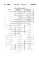
- FIG. 10shows an example of bit location values for status byte 934 in the packet format, according to another embodiment of the invention. For example, if monitoring and control unit 510 is used in conjunction with street lamps, each bit of the status byte can be used to convey monitoring data.
- bit valuesare listed in the table with the most significant bit (MSB) at the top of the table and the least significant bit (LSB) at the bottom.
- MSBmost significant bit
- LSBleast significant bit
- Bit 7can be used to indicate if an error condition has occurred.
- Bits 6-2are unused.
- Bit 1indicates whether daylight is present and will be set to 0 when the street lamp is turned on and set to 1 when the street lamp is turned off.
- Bit 0indicates whether AC voltage has been switched on to the street lamp. Bit 0 is set to 0 if the AC voltage is off and set to 1 if the AC voltage is on.
- FIGS. 11A-Cshow a base station 1100 for use in a monitoring and control system using RF, according to another embodiment of the invention.
- FIG. 11Ashows base station 1100 which includes an RX antenna system 1110, a receiving system front end 1120, a multi-port splitter 1130, a bank of RX modems 1140a-c, and a computing system 1150.
- RX antenna system 1110receives RF monitoring data and can be implemented using a single antenna or an array of interconnected antennas depending on the topology of the system. For example, if a directional antenna is used, RX antenna system 1110 may include an array of four of these directional antennas to provide 360 degrees of coverage.
- Receiving system front end 1120is coupled to RX antenna system 1110 for receiving the RF monitoring data.
- Receiving system front end 1120can also be implemented in a variety of ways. For example, a low noise amplifier (LNA) and pre-selecting filters can be used in applications which require high receiver sensitivity.
- LNAlow noise amplifier
- Receiving system front end 1120outputs received RF monitoring data.
- Multi-port splitter 1130is coupled to receiving system front end 1120 for receiving the received RF monitoring data.
- Multi-port splitter 1130takes the received RF monitoring data from receiving system front end 1120 and splits it to produce split RF monitoring data.
- RX modems 1140a-care coupled to multi-port splitter 1130 and receive the split RF monitoring data.
- RX modems 1140a-ceach demodulate their respective split RF monitoring data line to produce a respective received data signal.
- RX modems 1140a-ccan be operated in a variety of ways depending on the configuration of the system. For example, if twenty channels are being used, twenty RX modems 1140 can be used with each RX modem set to a different fixed frequency. On the other hand, in a more sophisticated configuration, frequency channels can be dynamically allocated to RX modems 1140a-c depending on the traffic requirements.
- Computing system 1150is coupled to RX modems 1140a-c for receiving the received data signals.
- Computing system 1150can include one or many individual computers. Additionally, the interface between computing system 1150 and RX modems 1140a-c can be any type of data interface, such as RS-232 or RS-422 for example.
- Computing system 1150includes an ID and status processing unit (ISPU) 1152 which processes ID and status data from the packets of monitoring data in the demodulated signals.
- ISPU 1152can be implemented as software, hardware, or firmware.
- computing system 1150can decode the packets of monitoring data in the demodulated signals, or can simply pass, without decoding, the packets of monitoring data on to another device, or can both decode and pass the packets of monitoring data.
- ISPU 1152can process and decode each packet.
- ISPU 1152can include a user interface, such as a graphical user interface, to allow an operator to view the monitoring data.
- ISPU 1152can include or interface to a database in which the monitoring data is stored.
- a databaseis particularly useful for producing statistical norms on the monitoring data either relating to one monitoring and control unit over a period of time or relating to performance of all of the monitoring and control units. For example, if the present invention is used for lamp monitoring and control, the current draw of a lamp can be monitored over a period of time and a profile created. Furthermore, an alarm threshold can be set if a new piece of monitored data deviates from the norm established in the profile. This feature is helpful for monitoring and controlling lamps because the precise current characteristics of each lamp can vary greatly. By allowing the database to create a unique profile for each lamp, the problem related to different lamp currents can be overcome so that an automated system for quickly identifying lamp problems is established.
- FIG. 11Bshows an alternate configuration for base station 1100, according to a further embodiment of the invention, which includes all of the elements discussed in regard to FIG. 11A and further includes a TX modem 1160, transmitting system 1162, and TX antenna 1164.
- Base station 1100 as shown in FIG. 11Bcan be used in applications which require a TX channel for control of remote devices 550.
- TX modem 1160is coupled to computing system 1150 for receiving control information.
- the control informationis modulated by TX modem 1160 to produce modulated control information.
- Transmitting system 1162is coupled to TX modem 1160 for receiving the modulated control information.
- Transmitting system 1162can have a variety of different configurations depending on the application. For example, if higher transmit power output is required, transmitting system 1162 can include a power amplifier. If necessary, transmitting system 1162 can include isolators, bandpass, lowpass, or highpass filters to prevent out-of-band signals. After receiving the modulated control information, transmitting system 1162 outputs a TX RF signal.
- TX antenna 1164is coupled to transmitting system 1162 for receiving the TX RF signal and transmitting a transmitted TX RF signal. It is well known to those skilled in the art that TX antenna 1164 may be coupled with RX antenna system 1110 using a duplexer for example.
- FIG. 11Cshows base station 1100 as part of a monitoring and control system, according to another embodiment of the invention.
- Base station 1100has already been described with reference to FIG. 11A.
- computing system 1150 of base station 1100can be coupled to a communication link 1170 for communicating with a main station 1180 or a further base station 1100a.
- Communication link 1170may be implemented using a variety of technologies such as: a standard phone line, DDS line, ISDN line, Ti, fiber optic line, or RF link.
- the topology of communication link 1170can vary depending on the application and can be: star, bus, ring, or mesh.
- FIG. 12shows a monitoring and control system 1200, according to another embodiment of the invention, having a main station 1230 coupled through a plurality of communication links 1220a-c to a plurality of respective base stations 1210a-c.
- Base stations 1210a-ccan have a variety of configurations such as those shown in FIGS. 11A-B.
- Communication links 1220a-callow respective base stations 1210a-c to pass monitoring data to main station 1230 and to receive control information from main station 1230. Processing of the monitoring data can either be performed at base stations 1210a-c or at main station 1230.
- FIG. 13shows a base station 1300 which is coupled to a communication server 1340 via a communication link 1330, according to another embodiment of the invention.
- Base station 1300includes an antenna and preselector system 1305, a receiver modem group (RMG) 1310, and a computing system 1320.
- RMGreceiver modem group
- Antenna and preselector system 1305are similar to RX antenna system 1110 and receiving system front end 1120 which were previously discussed.
- Antenna and preselector system 1305can include either one antenna or an array of antennas and preselection filtering as required by the application.
- Antenna and preselector system 1305receives RF monitoring data and outputs preselected RF monitoring data.
- Receiver modem group (RMG) 1310includes a low noise pre-amp 1312, a multi-port splitter 1314, and several RX modems 1316a-c.
- Low noise pre-amp 1312receives the preselected RF monitoring data from antenna and preselector system 1305 and outputs amplified RF monitoring data.
- Multi-port splitter 1314is coupled to low noise pre-amp 1312 for receiving the amplified RF monitoring data and outputting split RF monitoring data lines.
- RX modems 1316a-care coupled to multi-port splitter 1314 for receiving and demodulating one of the split RF monitoring data lines and outputting received data (RXD) 1324, received clock (RXC) 1326, and carrier detect (CD) 1328. These signals can use a standard interface such as RS-232 or RS-422 or can use a proprietary interface.
- Computing system 1320includes at least one base site computer 1322 for receiving RXD, RXC, and CD from RX modems 1316a-c, and outputting a serial data stream.
- Computing system 1320further includes an ID and status processing unit (ISPU) 1323 which processes ID and status data from the packets of monitoring data in RXD.
- ISPU 1323can be implemented as software, hardware, or firmware.
- computing system 1320can decode the packets of monitoring data in the demodulated signals, or can simply pass, without decoding, the packets of monitoring data on to another device in the serial data stream, or can both decode and pass the packets of monitoring data.
- Communication link 1330includes a first communication interface 1332, a second communication interface 1334, a first interface line 1336, a second interface line 1342, and a link 1338.
- First communication interface 1332receives the serial data stream from computing system 1320 of base station 1300 via first interface line 1336.
- First communication interface 1332can be co-located with computing system 1320 or be remotely located.
- First communication interface 1332can be implemented in a variety of ways using, for example, a CSU, DSU, or modem.
- Second communication interface 1334is coupled to first communication interface 1332 via link 1338.
- Link 1338can be implemented using a standard phone line, DDS line, ISDN line, Ti, fiber optic line, or RF link.
- Second communication interface 1334can be implemented similarly to first communication interface 1332 using, for example, a CSU, DSU, or modem.
- Communication link 1330outputs communicated serial data from second communication interface 1334 via second communication line 1342.
- Communication server 1340is coupled to communication link 1330 for receiving communicated serial data via second communication line 1342.
- Communication server 1340receives several lines of communicated serial data from several computing systems 1320 and multiplexes them to output multiplexed serial data on to a data network.
- the data networkcan be a public or private data network such as an internet or intranet.
- FIGS. 14A-Eshow methods for implementation of logic for lamp monitoring and control system 600, according to a further embodiment of the invention.
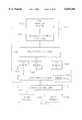
- FIG. 14Ashows one method for energizing and de-energizing a street lamp and transmitting associated monitoring data.
- the method of FIG. 14Ashows a single transmission for each control event.
- the methodbegins with a start block 1400 and proceeds to step 1410 which involves checking AC and Daylight Status.
- the Check AC and Daylight Status step 1410is used to check for conditions where the AC power and/or the Daylight Status have changed. If a change does occur, the method proceeds to step 1420 which is a decision block based on the change.
- step 1420proceeds to a Debounce Delay step 1422 which involves inserting a Debounce Delay.
- the Debounce Delaymay be 0.5 seconds. After Debounce Delay step 1422, the method leads back to Check AC and Daylight Status step 1410.
- step 1420proceeds to step 1430 which is a decision block to determine whether the lamp should be energized. If the lamp should be energized, then the method proceeds to step 1432 which turns the lamp on. After step 1432 when the lamp is turned on, the method proceeds to step 1434 which involves Current Stabilization Delay to allow the current in the street lamp to stabilize. The amount of delay for current stabilization depends upon the type of lamp used. However, for a typical vapor lamp a ten minute stabilization delay is appropriate. After step 1434, the method leads back to step 1410 which checks AC and Daylight Status.
- step 1440is a decision block to check to deenergize the lamp. If the lamp is to be deenergized, the method proceeds to step 1442 which involves turning the Lamp Off. After the lamp is turned off, the method proceeds to step 1444 in which the relay is allowed a Settle Delay time. The Settle Delay time is dependent upon the particular relay used and may be, for example, set to 0.5 seconds. After step 1444, the method returns to step 1410 to check the AC and Daylight Status.
- step 1440if the lamp is not to be deenergized, the method proceeds to step 1450 in which an error bit is set, if required. The method then proceeds to step 1460 in which an A/D is read.
- step 1460the method then proceeds from step 1460 to step 1470 which checks to see if a transmit is required. If no transmit is required, the method proceeds to step 1472 in which a Scan Delay is executed.
- the Scan Delaydepends upon the circuitry used and, for example, may be 0.5 seconds. After step 1472, the method returns to step 1410 which checks AC and Daylight Status.
- step 1470if a transmit is required, then the method proceeds to step 1480 which performs a transmit operation. After the transmit operation of step 1480 is completed, the method then returns to step 1410 which checks AC and Daylight Status.
- FIG. 14Bis analogous to FIG. 14A with one modification. This modification occurs after step 1420. If a change has occurred, rather than simply executing step 1422, the Debounce Delay, the method performs a further step 1424 which involves checking whether daylight has occurred. If daylight has not occurred, then the method proceeds to step 1426 which executes an Initial Delay. This initial delay may be, for example, 0.5 seconds. After step 1426, the method proceeds to step 1422 and follows the same method as shown in FIG. 14A.
- step 1428executes an Initial Delay.
- the Initial Delay associated with step 1428should be a significantly larger value than the Initial Delay associated with step 1426. For example, an Initial Delay of 45 seconds may be used.
- the Initial Delay of step 1428is used to prevent a false triggering which deenergizes the lamp. In actual practice, this extended delay can become very important because if the lamp is inadvertently deenergized too soon, it requires a substantial amount of time to reenergize the lamp (for example, ten minutes).
- step 1422executes a Debounce Delay and then returns to step 1410 as shown in FIGS. 14A and 14B.
- FIG. 14Cshows a method for transmitting monitoring data multiple times in monitoring and control unit 510, according to a further embodiment of the invention. This method is particularly important in applications in which monitoring and control unit 510 does not have a RX unit 540 for receiving acknowledgments of transmissions.
- the methodbegins with a transmit start block 1482 and proceeds to step 1484 which involves initializing a count value, i.e. setting the count value to zero.
- the methodproceeds from step 1484 to step 1486 which involves setting a variable x to a value associated with a serial number of monitoring and control unit 510.
- variable xmay be set to 50 times the lowest nibble of the serial number.
- step 1488which involves waiting a reporting start time delay associated with the value x.
- the reporting start timeis the amount of delay time before the first transmission.
- this delay timemay be set to x seconds where x is an integer between 1 and 32,000 or more. This example range for x is particularly useful in the street lamp application since it distributes the packet reporting start times over more than eight hours, approximately the time from sunset to sunrise.
- step 1490a variable y representing a channel number is set.
- ymay be set to the integer value of RTC/12.8, where RTC represents a real time clock counting from 0-255 as fast as possible.
- the RTCmay be included in processing and sensing unit 520.
- step 1490proceeds from step 1490 to step 1492 in which a packet is transmitted on channel y.
- step 1492proceeds to step 1494 in which the count value is incremented.
- step 1494proceeds to step 1496 which is a decision block to determine if the count value equals an upper limit N.
- step 1496the method returns from step 1496 to step 1488 and waits another delay time associated with variable x.
- This delay timeis the reporting delta time since it represents the time difference between two consecutive reporting events.
- step 1496the method proceeds from step 1496 to step 1498 which is an end block.
- the value for Nmust be determined based on the specific application. Increasing the value of N decreases the probability of a unsuccessful transmission since the same data is being sent multiple times and the probability of all of the packets being lost decreases as N increases. However, increasing the value of N increases the amount of traffic which may become an issue in a monitoring and control system with a plurality of monitoring and control units.
- FIG. 14Dshows a method for transmitting monitoring data multiple times in a monitoring and control system according to a another embodiment of the invention.
- the methodbegins with a transmit start block 1410' and proceeds to step 1412' which involves initializing a count value, i.e., setting the count value to 1.
- the methodproceeds from step 1412' to step 1414' which involves randomizing the reporting start time delay.
- the reporting start time delayis the amount of time delay required before the transmission of the first data packet.
- a variety of methodscan be used for this randomization process such as selecting a pseudo-random value or basing the randomization on the serial number of monitoring and control unit 510.
- step 1414'The method proceeds from step 1414' to step 1416' which involves checking to see if the count equals 1. If the count is equal to 1, then the method proceeds to step 1420' which involves setting a reporting delta time equal to the reporting start time delay. If the count is not equal to 1, the method proceeds to step 1418' which involves randomizing the reporting delta time.
- the reporting delta timeis the difference in time between each reporting event. A variety of methods can be used for randomizing the reporting delta time including selecting a pseudo-random value or selecting a random number based upon the serial number of the monitoring and control unit 510.
- step 1422'which involves randomizing a transmit channel number.
- the transmit channel numberis a number indicative of the frequency used for transmitting the monitoring data.
- There are a variety of methods for randomizing the transmit channel numbersuch as selecting a pseudo-random number or selecting a random number based upon the serial number of the monitoring and control unit 510.
- step 1424'which involves waiting the reporting delta time.
- the reporting delta timeis the time which was selected during the randomization process of step 1418' or the reporting start time delay selected in step 1414', if the count equals 1.
- the use of separate randomization steps 1414' and 1418'is important because it allows the use of different randomization functions for the reporting start time delay and the reporting delta time, respectively.
- step 1424'the method proceeds to step 1426' which involves transmitting a packet on the transmit channel selected in step 1422'.
- step 1426'proceeds from step 1426' to step 1428' which involves incrementing the counter for the number of packet transmissions.
- step 1428'the count is compared with a value N which represents the maximum number of transmissions for each packet. If the count is less than or equal to N, then the method proceeds from step 1430' back to step 1418' which involves randomizing the reporting delta time for the next transmission. If the count is greater than N, then the method proceeds from step 1430' to the end block 1432' for the transmission method.
- the methodwill continue transmission of the same packet of data N times, with randomization of the reporting start time delay, randomization of the reporting delta times between each reporting event, and randomization of the transmit channel number for each packet.
- These multiple randomizationshelp stagger the packets in the frequency and time domain to reduce the probability of collisions of packets from different monitoring and control units.
- FIG. 14Eshows a further method for transmitting monitoring data multiple times from a monitoring and control unit 510, according to another embodiment of the invention.
- the methodbegins with a transmit start block 1440' and proceeds to step 1442' which involves initializing a count value, i.e., setting the count value to 1.
- the methodproceeds from step 1442' to step 1444' which involves reading an indicator, such as a group jumper, to determine which group of frequencies to use, Group A or B. Examples of Group A and Group B channel numbers and frequencies can be found in FIG. 8.
- Step 1444'proceeds to step 1446' which makes a decision based upon whether Group A or B is being used. If Group A is being used, step 1446' proceeds to step 1448' which involves setting a base channel to the appropriate frequency for Group A. If Group B is to be used, step 1446' proceeds to step 1450' which involves setting the base channel frequency to a frequency for Group B.
- Step 1452'involves randomizing a reporting start time delay.
- the randomizationcan be achieved by multiplying the lowest nibble of the serial number of monitoring and control unit 510 by 50 and using the resulting value, x, as the number of milliseconds for the reporting start time delay.
- step 1452'The method proceeds from step 1452' to step 1454' which involves waiting x number of seconds as determined in step 1452'.
- step 1456'proceeds to step 1458' which determines whether the count equals 1. If the count equals 1, the method proceeds from step 1458' to step 1472' which involves transmitting the packet on a channel determined from the base channel frequency selected in either step 1448' or step 1450' plus the channel frequency offset selected in step 1456'.
- step 1458'determines whether the count is equal to N, where N represents the maximum number of packet transmissions. If the count is equal to N, then the method proceeds from step 1460' to step 1472' which involves transmitting the packet on a channel determined from the base channel frequency selected in either step 1448' or step 1450' plus the channel number offset selected in step 1456'.
- step 1460'If the count is not equal to N, indicating that the count is a value between 1 and N, then the method proceeds from step 1460' to step 1462' which involves reading a real time counter (RTC) which may be located in processing and sensing unit 412.
- RTCreal time counter
- step 1462'The method proceeds from step 1462' to step 1464' which involves comparing the RTC value against a maximum value, for example, a maximum value of 152. If the RTC value is greater than or equal to the maximum value, then the method proceeds from step 1464' to step 1466' which involves waiting x seconds and returning to step 1462'.
- a maximum valuefor example, a maximum value of 152.
- step 1464'the method proceeds from step 1464' to step 1468' which involves setting a value y equal to a value indicative of the channel number offset.
- ycan be set to an integer of the real time counter value divided by 8, so that Y value would range from 0 to 18.
- step 1468'The method proceeds from step 1468' to step 1470' which involves computing a frequency offset value z from the channel number offset value y. For example, if a 25 KHz channel is being used, then z is equal to y times 25 KHz.
- step 1470'which involves transmitting the packet on a channel determined from the base channel frequency selected in either step 1448' or step 1450' plus the channel frequency offset computed in step 1470'.
- step 1474'which involves incrementing the count value.
- step 1476'which involves comparing the count value to a value N+1 which is related to the maximum number of transmissions for each packet. If the count is not equal to N+1, the method proceeds from step 1476' back to step 1454' which involves waiting x number of milliseconds. If the count is equal to N+1, the method proceeds from step 1476' to the end block 1478'.
- the method shown in FIG. 14Eis similar to that shown in FIG. 14D, but differs in that it requires the first and the Nth transmission to occur at the base frequency rather than a randomly selected frequency.
Landscapes
- Circuit Arrangement For Electric Light Sources In General (AREA)
Abstract
Description
Claims (22)
Priority Applications (14)
| Application Number | Priority Date | Filing Date | Title |
|---|---|---|---|
| US08/838,303US6035266A (en) | 1997-04-16 | 1997-04-16 | Lamp monitoring and control system and method |
| US08/942,681US6359555B1 (en) | 1997-04-16 | 1997-10-02 | Alarm monitoring and control system and method |
| PCT/US1998/007498WO1998047120A1 (en) | 1997-04-16 | 1998-04-15 | Monitoring and control systems and methods |
| AU74664/98AAU7466498A (en) | 1997-04-16 | 1998-04-15 | Monitoring and control systems and methods |
| US09/465,795US6415245B2 (en) | 1997-04-16 | 1999-12-17 | Lamp monitoring and control system and method |
| US09/576,545US6370489B1 (en) | 1997-04-16 | 2000-05-22 | Lamp monitoring and control system and method |
| US09/575,531US6393382B1 (en) | 1997-04-16 | 2000-05-22 | Lamp monitoring and control system and method |
| US09/637,916US6384722B1 (en) | 1997-04-16 | 2000-08-14 | Lamp monitoring and control system and method |
| US10/100,091US6636150B2 (en) | 1997-04-16 | 2002-03-19 | Lamp monitoring and control system and method |
| US10/118,324US6604062B2 (en) | 1997-04-16 | 2002-04-09 | Lamp monitoring and control system and method |
| US10/628,353US6807516B2 (en) | 1997-04-16 | 2003-07-29 | Lamp monitoring and control system and method |
| US10/834,869US6892168B2 (en) | 1997-04-16 | 2004-04-30 | Lamp monitoring and control system and method |
| US11/117,510US7120560B2 (en) | 1997-04-16 | 2005-04-29 | Lamp monitoring and control system and method |
| US11/544,869US20070032990A1 (en) | 1997-04-16 | 2006-10-10 | Lamp monitoring and control system and method |
Applications Claiming Priority (1)
| Application Number | Priority Date | Filing Date | Title |
|---|---|---|---|
| US08/838,303US6035266A (en) | 1997-04-16 | 1997-04-16 | Lamp monitoring and control system and method |
Related Parent Applications (2)
| Application Number | Title | Priority Date | Filing Date |
|---|---|---|---|
| US08/838,302Continuation-In-PartUS6119076A (en) | 1997-04-16 | 1997-04-16 | Lamp monitoring and control unit and method |
| US09/465,795DivisionUS6415245B2 (en) | 1997-04-16 | 1999-12-17 | Lamp monitoring and control system and method |
Related Child Applications (3)
| Application Number | Title | Priority Date | Filing Date |
|---|---|---|---|
| US08/942,681Continuation-In-PartUS6359555B1 (en) | 1997-04-16 | 1997-10-02 | Alarm monitoring and control system and method |
| US09/465,795DivisionUS6415245B2 (en) | 1997-04-16 | 1999-12-17 | Lamp monitoring and control system and method |
| US09/575,531DivisionUS6393382B1 (en) | 1997-04-16 | 2000-05-22 | Lamp monitoring and control system and method |
Publications (1)
| Publication Number | Publication Date |
|---|---|
| US6035266Atrue US6035266A (en) | 2000-03-07 |
Family
ID=25276768
Family Applications (9)
| Application Number | Title | Priority Date | Filing Date |
|---|---|---|---|
| US08/838,303Expired - LifetimeUS6035266A (en) | 1997-04-16 | 1997-04-16 | Lamp monitoring and control system and method |
| US09/465,795Expired - LifetimeUS6415245B2 (en) | 1997-04-16 | 1999-12-17 | Lamp monitoring and control system and method |
| US09/575,531Expired - LifetimeUS6393382B1 (en) | 1997-04-16 | 2000-05-22 | Lamp monitoring and control system and method |
| US09/576,545Expired - LifetimeUS6370489B1 (en) | 1997-04-16 | 2000-05-22 | Lamp monitoring and control system and method |
| US10/118,324Expired - LifetimeUS6604062B2 (en) | 1997-04-16 | 2002-04-09 | Lamp monitoring and control system and method |
| US10/628,353Expired - Fee RelatedUS6807516B2 (en) | 1997-04-16 | 2003-07-29 | Lamp monitoring and control system and method |
| US10/834,869Expired - Fee RelatedUS6892168B2 (en) | 1997-04-16 | 2004-04-30 | Lamp monitoring and control system and method |
| US11/117,510Expired - Fee RelatedUS7120560B2 (en) | 1997-04-16 | 2005-04-29 | Lamp monitoring and control system and method |
| US11/544,869AbandonedUS20070032990A1 (en) | 1997-04-16 | 2006-10-10 | Lamp monitoring and control system and method |
Family Applications After (8)
| Application Number | Title | Priority Date | Filing Date |
|---|---|---|---|
| US09/465,795Expired - LifetimeUS6415245B2 (en) | 1997-04-16 | 1999-12-17 | Lamp monitoring and control system and method |
| US09/575,531Expired - LifetimeUS6393382B1 (en) | 1997-04-16 | 2000-05-22 | Lamp monitoring and control system and method |
| US09/576,545Expired - LifetimeUS6370489B1 (en) | 1997-04-16 | 2000-05-22 | Lamp monitoring and control system and method |
| US10/118,324Expired - LifetimeUS6604062B2 (en) | 1997-04-16 | 2002-04-09 | Lamp monitoring and control system and method |
| US10/628,353Expired - Fee RelatedUS6807516B2 (en) | 1997-04-16 | 2003-07-29 | Lamp monitoring and control system and method |
| US10/834,869Expired - Fee RelatedUS6892168B2 (en) | 1997-04-16 | 2004-04-30 | Lamp monitoring and control system and method |
| US11/117,510Expired - Fee RelatedUS7120560B2 (en) | 1997-04-16 | 2005-04-29 | Lamp monitoring and control system and method |
| US11/544,869AbandonedUS20070032990A1 (en) | 1997-04-16 | 2006-10-10 | Lamp monitoring and control system and method |
Country Status (1)
| Country | Link |
|---|---|
| US (9) | US6035266A (en) |
Cited By (70)
| Publication number | Priority date | Publication date | Assignee | Title |
|---|---|---|---|---|
| WO2001095646A1 (en)* | 2000-06-07 | 2001-12-13 | Telemics, Inc. | Method and system for monitoring and controlling working components |
| US6370489B1 (en) | 1997-04-16 | 2002-04-09 | A.L. Air Data | Lamp monitoring and control system and method |
| US6384722B1 (en)* | 1997-04-16 | 2002-05-07 | A.L. Air Data, Inc. | Lamp monitoring and control system and method |
| US6393381B1 (en)* | 1997-04-16 | 2002-05-21 | A.L. Air Data, Inc. | Lamp monitoring and control unit and method |
| GB2372160A (en)* | 2001-02-09 | 2002-08-14 | Larry Taylor | Street light management |
| US6436299B1 (en) | 1999-06-21 | 2002-08-20 | Amway Corporation | Water treatment system with an inductively coupled ballast |
| US20020125998A1 (en)* | 1998-06-22 | 2002-09-12 | Petite Thomas D. | System and method for monitoring and controlling remote devices |
| US6451202B1 (en) | 1999-06-21 | 2002-09-17 | Access Business Group International Llc | Point-of-use water treatment system |
| US6673250B2 (en) | 1999-06-21 | 2004-01-06 | Access Business Group International Llc | Radio frequency identification system for a fluid treatment system |
| GB2392326A (en)* | 2002-08-20 | 2004-02-25 | Christopher Laurie Malthouse | System for monitoring street lighting |
| US6714895B2 (en)* | 2000-06-28 | 2004-03-30 | A.L. Air Data, Inc. | Lamp monitoring and control unit and method |
| US20040254725A1 (en)* | 2001-11-19 | 2004-12-16 | Eric Douville | System for locating and addressing the lights of a beacon network |
| US20050043059A1 (en)* | 2000-08-09 | 2005-02-24 | Petite Thomas D. | Systems and methods for providing remote monitoring of electricity consumption for an electric meter |
| GB2405693A (en)* | 2003-08-04 | 2005-03-09 | Darryl Schofield | Automatic light monitoring means |
| US20060092638A1 (en)* | 2004-10-28 | 2006-05-04 | Harwood Ronald P | Housing for intelligent lights |
| US7079810B2 (en) | 1997-02-14 | 2006-07-18 | Statsignal Ipc, Llc | System and method for communicating with a remote communication unit via the public switched telephone network (PSTN) |
| US7103511B2 (en) | 1998-10-14 | 2006-09-05 | Statsignal Ipc, Llc | Wireless communication networks for providing remote monitoring of devices |
| US7137550B1 (en) | 1997-02-14 | 2006-11-21 | Statsignal Ipc, Llc | Transmitter for accessing automated financial transaction machines |
| US20070057807A1 (en)* | 2005-09-12 | 2007-03-15 | Acuity Brands, Inc. | Activation device for an intelligent luminaire manager |
| US7263073B2 (en) | 1999-03-18 | 2007-08-28 | Statsignal Ipc, Llc | Systems and methods for enabling a mobile user to notify an automated monitoring system of an emergency situation |
| US7295128B2 (en) | 1998-06-22 | 2007-11-13 | Sipco, Llc | Smoke detection methods, devices, and systems |
| US7346463B2 (en) | 2001-08-09 | 2008-03-18 | Hunt Technologies, Llc | System for controlling electrically-powered devices in an electrical network |
| US20080097782A1 (en)* | 1998-05-29 | 2008-04-24 | Powerweb, Inc. | Multi-utility energy control and facility automation system with dashboard having a plurality of interface gateways |
| US7397907B2 (en) | 1997-02-14 | 2008-07-08 | Sipco, Llc | Multi-function general purpose transceiver |
| US7424527B2 (en) | 2001-10-30 | 2008-09-09 | Sipco, Llc | System and method for transmitting pollution information over an integrated wireless network |
| US7480501B2 (en) | 2001-10-24 | 2009-01-20 | Statsignal Ipc, Llc | System and method for transmitting an emergency message over an integrated wireless network |
| US20090066258A1 (en)* | 2007-09-07 | 2009-03-12 | Streetlight Intelligence, Inc. | Streelight monitoring and control |
| US20090066540A1 (en)* | 2007-09-07 | 2009-03-12 | Dimitri Marinakis | Centralized route calculation for a multi-hop streetlight network |
| US7650425B2 (en) | 1999-03-18 | 2010-01-19 | Sipco, Llc | System and method for controlling communication between a host computer and communication devices associated with remote devices in an automated monitoring system |
| US7697492B2 (en) | 1998-06-22 | 2010-04-13 | Sipco, Llc | Systems and methods for monitoring and controlling remote devices |
| US7756086B2 (en) | 2004-03-03 | 2010-07-13 | Sipco, Llc | Method for communicating in dual-modes |
| US7817063B2 (en) | 2005-10-05 | 2010-10-19 | Abl Ip Holding Llc | Method and system for remotely monitoring and controlling field devices with a street lamp elevated mesh network |
| US20100295482A1 (en)* | 2009-04-14 | 2010-11-25 | Digital Lumens, Inc. | Power Management Unit with Multi-Input Arbitration |
| US20100295473A1 (en)* | 2008-04-14 | 2010-11-25 | Digital Lumens, Inc. | Power Management Unit with Sensor Logging |
| US20100301771A1 (en)* | 2008-04-14 | 2010-12-02 | Digital Lumens, Inc. | Power Management Unit with Power Source Arbitration |
| US20100301774A1 (en)* | 2008-04-14 | 2010-12-02 | Digital Lumens, Inc. | Power Management Unit with Automatic Output Configuration |
| US20110001436A1 (en)* | 2008-04-14 | 2011-01-06 | Digital Lumens, Inc. | Power Management Unit with Light Module Identification |
| US20110057570A1 (en)* | 2005-06-30 | 2011-03-10 | Streetlight Intelligence, Inc. | Method and System for Luminance Characterization |
| US20110144773A1 (en)* | 2008-08-14 | 2011-06-16 | Koninklijke Philips Electronics N.V. | Method and apparatus for altering the behavior of a networked control system |
| US20110185349A1 (en)* | 2010-01-28 | 2011-07-28 | Empower Electronics, Inc. | Lamp ballast configured to operate in a self-forming network |
| US8000314B2 (en) | 1996-12-06 | 2011-08-16 | Ipco, Llc | Wireless network system and method for providing same |
| US8031650B2 (en) | 2004-03-03 | 2011-10-04 | Sipco, Llc | System and method for monitoring remote devices with a dual-mode wireless communication protocol |
| US8064412B2 (en) | 1998-06-22 | 2011-11-22 | Sipco, Llc | Systems and methods for monitoring conditions |
| US20120062123A1 (en)* | 2010-09-09 | 2012-03-15 | Jarrell John A | Managing Light System Energy Use |
| US8140276B2 (en) | 2008-02-27 | 2012-03-20 | Abl Ip Holding Llc | System and method for streetlight monitoring diagnostics |
| EP1685497A4 (en)* | 2003-11-04 | 2012-12-19 | Powerweb Technologies | INTERNET WIRELESS LIGHTING CONTROL SYSTEM |
| US8410931B2 (en) | 1998-06-22 | 2013-04-02 | Sipco, Llc | Mobile inventory unit monitoring systems and methods |
| US8433426B2 (en) | 2005-06-30 | 2013-04-30 | Led Roadway Lighting Ltd | Adaptive energy performance monitoring and control system |
| US8489063B2 (en) | 2001-10-24 | 2013-07-16 | Sipco, Llc | Systems and methods for providing emergency messages to a mobile device |
| GB2501985A (en)* | 2012-04-05 | 2013-11-13 | Justing Tech Taiwan Pte Ltd | Light fixture remote controlling system |
| US8787246B2 (en) | 2009-02-03 | 2014-07-22 | Ipco, Llc | Systems and methods for facilitating wireless network communication, satellite-based wireless network systems, and aircraft-based wireless network systems, and related methods |
| EP1937036A3 (en)* | 2006-12-19 | 2015-01-14 | Korea Electro Technology Research Institute | Wireless communication based safer street lamp control system |
| US8960967B2 (en) | 2004-10-28 | 2015-02-24 | Ronald P. Harwood | Housing for intelligent lights |
| US9014829B2 (en) | 2010-11-04 | 2015-04-21 | Digital Lumens, Inc. | Method, apparatus, and system for occupancy sensing |
| US9072133B2 (en) | 2008-04-14 | 2015-06-30 | Digital Lumens, Inc. | Lighting fixtures and methods of commissioning lighting fixtures |
| US9161419B2 (en) | 2012-07-02 | 2015-10-13 | International Business Machines Corporation | Intelligent and coordinated lighting of a lighting device |
| US9241392B2 (en) | 2012-03-19 | 2016-01-19 | Digital Lumens, Inc. | Methods, systems, and apparatus for providing variable illumination |
| US9439126B2 (en) | 2005-01-25 | 2016-09-06 | Sipco, Llc | Wireless network protocol system and methods |
| US9510426B2 (en) | 2011-11-03 | 2016-11-29 | Digital Lumens, Inc. | Methods, systems, and apparatus for intelligent lighting |
| WO2017054021A1 (en)* | 2015-09-30 | 2017-04-06 | Tridonic Gmbh & Co Kg | Lighting state synchronization |
| US9693428B2 (en) | 2014-10-15 | 2017-06-27 | Abl Ip Holding Llc | Lighting control with automated activation process |
| CN107071999A (en)* | 2017-03-23 | 2017-08-18 | 金华送变电工程有限公司路灯分公司 | A kind of streetlight monitoring device |
| US9781814B2 (en) | 2014-10-15 | 2017-10-03 | Abl Ip Holding Llc | Lighting control with integral dimming |
| US9924576B2 (en) | 2013-04-30 | 2018-03-20 | Digital Lumens, Inc. | Methods, apparatuses, and systems for operating light emitting diodes at low temperature |
| US10230634B2 (en) | 2015-09-25 | 2019-03-12 | Osram Sylvania Inc. | Route optimization using star-mesh hybrid topology in localized dense ad-hoc networks |
| US10264652B2 (en) | 2013-10-10 | 2019-04-16 | Digital Lumens, Inc. | Methods, systems, and apparatus for intelligent lighting |
| US10485068B2 (en) | 2008-04-14 | 2019-11-19 | Digital Lumens, Inc. | Methods, apparatus, and systems for providing occupancy-based variable lighting |
| US10529221B2 (en) | 2016-04-19 | 2020-01-07 | Navio International, Inc. | Modular approach for smart and customizable security solutions and other applications for a smart city |
| US10891881B2 (en) | 2012-07-30 | 2021-01-12 | Ultravision Technologies, Llc | Lighting assembly with LEDs and optical elements |
| US12231337B2 (en) | 2015-09-25 | 2025-02-18 | Digital Lumens Incorporated | Route optimization using star-mesh hybrid topology in localized dense ad-hoc networks |
Families Citing this family (99)
| Publication number | Priority date | Publication date | Assignee | Title |
|---|---|---|---|---|
| FI111760B (en)* | 1999-04-16 | 2003-09-15 | Metso Automation Oy | Wireless control of a field device in an industrial process |
| SI1201010T1 (en)* | 1999-06-08 | 2004-12-31 | Lempia-Laboratoire D'electronique, Mecanique, Pyrotechnique Et | Network for remote administration of street lighting inter alia and methods to carry out said administration |
| US6681110B1 (en)* | 1999-07-02 | 2004-01-20 | Musco Corporation | Means and apparatus for control of remote electrical devices |
| US7049761B2 (en) | 2000-02-11 | 2006-05-23 | Altair Engineering, Inc. | Light tube and power supply circuit |
| WO2002023865A2 (en)* | 2000-09-14 | 2002-03-21 | Musco Corporation | System and method for remote controlling of sports lights |
| DE10052541A1 (en)* | 2000-10-23 | 2002-04-25 | Patent Treuhand Ges Fuer Elektrische Gluehlampen Mbh | Method for triggering a sensor-controlled lamp uses a microprocessor to evaluate sensor signals and apply any time change in them to change or activate lamp control operating parameters. |
| US8180516B2 (en)* | 2002-06-06 | 2012-05-15 | Continental Automotive Systems, Inc. | Driver information interface and method of managing driver information |
| US6933849B2 (en) | 2002-07-09 | 2005-08-23 | Fred Sawyer | Method and apparatus for tracking objects and people |
| US20040112132A1 (en)* | 2002-08-23 | 2004-06-17 | Fioravanti Louis J. | Rotational stabilization of disc drives dring servo track writing operations |
| US7440735B2 (en)* | 2002-10-23 | 2008-10-21 | Rosemount Inc. | Virtual wireless transmitter |
| IL154459A0 (en)* | 2003-02-13 | 2003-09-17 | Witcom Ltd | Wireless network with intensive frequency reuse |
| JP4279033B2 (en)* | 2003-04-07 | 2009-06-17 | 三菱電機株式会社 | Discharge lamp lighting device for in-vehicle headlights |
| US7956551B1 (en) | 2004-02-24 | 2011-06-07 | Musco Corporation | Apparatus and method for discretionary adjustment of lumen output of light sources having lamp lumen depreciation characteristic compensation |
| US7956556B1 (en) | 2004-02-24 | 2011-06-07 | Musco Corporation | Apparatus and method for compensating for reduced light output of a solid-state light source having a lumen depreciation characteristic over its operational life |
| GB0406983D0 (en)* | 2004-03-29 | 2004-04-28 | Brison Paul | Wireless controlled intelligent outdoor dimmer module |
| KR101013140B1 (en)* | 2004-06-18 | 2011-02-10 | 삼성전자주식회사 | Multi display system and its control method |
| EP1698826A1 (en)* | 2005-03-02 | 2006-09-06 | Noontek Limited | A street lamp assembly |
| CN100446353C (en)* | 2005-12-28 | 2008-12-24 | 上海科正电子科技有限公司 | Intelligent remote control lamp holder device |
| EP1865756A1 (en)* | 2006-06-06 | 2007-12-12 | Nesa A/S | Lighting system |
| WO2008021120A2 (en)* | 2006-08-07 | 2008-02-21 | James Thor Williams | Controlling parking lot lighting |
| US7731383B2 (en)* | 2007-02-02 | 2010-06-08 | Inovus Solar, Inc. | Solar-powered light pole and LED light fixture |
| EP2132961B1 (en)* | 2007-03-27 | 2021-05-12 | Signify Holding B.V. | Control circuit, system for operating a device and device for programming such a control circuit |
| US8035320B2 (en) | 2007-04-20 | 2011-10-11 | Sibert W Olin | Illumination control network |
| US8331796B2 (en)* | 2007-09-26 | 2012-12-11 | Koninklijke Philips Electronics N.V. | Method and device for communicating data using a light source |
| US8118447B2 (en) | 2007-12-20 | 2012-02-21 | Altair Engineering, Inc. | LED lighting apparatus with swivel connection |
| WO2009118696A1 (en)* | 2008-03-25 | 2009-10-01 | Yeoshua Barak | Power regulation and control system therefor |
| US8360599B2 (en) | 2008-05-23 | 2013-01-29 | Ilumisys, Inc. | Electric shock resistant L.E.D. based light |
| WO2010014925A2 (en)* | 2008-07-31 | 2010-02-04 | Ming Solar, Inc. | Wireless autonomous solar-powered outdoor lighting and energy and information management network |
| US8674626B2 (en)* | 2008-09-02 | 2014-03-18 | Ilumisys, Inc. | LED lamp failure alerting system |
| US8901823B2 (en) | 2008-10-24 | 2014-12-02 | Ilumisys, Inc. | Light and light sensor |
| US8324817B2 (en) | 2008-10-24 | 2012-12-04 | Ilumisys, Inc. | Light and light sensor |
| US8214084B2 (en) | 2008-10-24 | 2012-07-03 | Ilumisys, Inc. | Integration of LED lighting with building controls |
| US7938562B2 (en) | 2008-10-24 | 2011-05-10 | Altair Engineering, Inc. | Lighting including integral communication apparatus |
| US8653984B2 (en) | 2008-10-24 | 2014-02-18 | Ilumisys, Inc. | Integration of LED lighting control with emergency notification systems |
| KR101781399B1 (en) | 2008-11-17 | 2017-09-25 | 익스프레스 이미징 시스템즈, 엘엘씨 | Electronic control to regulate power for solid-state lighting and methods thereof |
| US8098017B2 (en)* | 2009-01-22 | 2012-01-17 | Daniel William Chidester | Automatic, low level floor lighting system |
| US8816840B1 (en)* | 2009-04-04 | 2014-08-26 | Classic Safety Products, LLC | Self-contained, removable, wireless turn signal system for motor vehicles and trailers |
| WO2010127138A2 (en)* | 2009-05-01 | 2010-11-04 | Express Imaging Systems, Llc | Gas-discharge lamp replacement with passive cooling |
| US8436542B2 (en) | 2009-05-04 | 2013-05-07 | Hubbell Incorporated | Integrated lighting system and method |
| WO2010135575A2 (en) | 2009-05-20 | 2010-11-25 | Express Imaging Systems, Llc | Long-range motion detection for illumination control |
| US8541950B2 (en) | 2009-05-20 | 2013-09-24 | Express Imaging Systems, Llc | Apparatus and method of energy efficient illumination |
| EP2262350A1 (en)* | 2009-06-10 | 2010-12-15 | iLEDs GmbH | Lighting unit, network of lighting units and method for controlling the light intensity of a lighting network comprising at least one lighting unit |
| TWI397234B (en)* | 2009-09-30 | 2013-05-21 | Yun Chang Liao | Remote monitoring system of lighting device and its monitoring method |
| IT1399550B1 (en)* | 2009-10-05 | 2013-04-19 | Hutter | SYSTEM FOR DETECTING THE LAMPS IN THE PUBLIC LIGHTING SYSTEMS |
| TW201127195A (en)* | 2010-01-27 | 2011-08-01 | Shi-Zong Ceng | Interactively controlled energy-saving LED street light device |
| US8853965B2 (en)* | 2010-02-01 | 2014-10-07 | Twisthink, L.L.C. | Luminary control systems |
| US8540401B2 (en) | 2010-03-26 | 2013-09-24 | Ilumisys, Inc. | LED bulb with internal heat dissipating structures |
| CA2792940A1 (en) | 2010-03-26 | 2011-09-19 | Ilumisys, Inc. | Led light with thermoelectric generator |
| US9173267B2 (en) | 2010-04-01 | 2015-10-27 | Michael L. Picco | Modular centralized lighting control system for buildings |
| TWI462652B (en)* | 2010-06-22 | 2014-11-21 | Hugewin Electronics Co Ltd | Wireless remote control and remote control dimming light bulb device with signal response and forwarding |
| EP2633227B1 (en) | 2010-10-29 | 2018-08-29 | iLumisys, Inc. | Mechanisms for reducing risk of shock during installation of light tube |
| US10564613B2 (en) | 2010-11-19 | 2020-02-18 | Hubbell Incorporated | Control system and method for managing wireless and wired components |
| US8901825B2 (en) | 2011-04-12 | 2014-12-02 | Express Imaging Systems, Llc | Apparatus and method of energy efficient illumination using received signals |
| US20130044488A1 (en)* | 2011-08-17 | 2013-02-21 | G. Albert Hreish | Combination Lamp and Wireless Network Access System |
| US9072171B2 (en) | 2011-08-24 | 2015-06-30 | Ilumisys, Inc. | Circuit board mount for LED light |
| EP2781138A4 (en) | 2011-11-18 | 2015-10-28 | Express Imaging Systems Llc | Adjustable output solid-state lamp with security features |
| US9360198B2 (en) | 2011-12-06 | 2016-06-07 | Express Imaging Systems, Llc | Adjustable output solid-state lighting device |
| US9497393B2 (en) | 2012-03-02 | 2016-11-15 | Express Imaging Systems, Llc | Systems and methods that employ object recognition |
| US9184518B2 (en) | 2012-03-02 | 2015-11-10 | Ilumisys, Inc. | Electrical connector header for an LED-based light |
| US9210751B2 (en) | 2012-05-01 | 2015-12-08 | Express Imaging Systems, Llc | Solid state lighting, drive circuit and method of driving same |
| US9204523B2 (en) | 2012-05-02 | 2015-12-01 | Express Imaging Systems, Llc | Remotely adjustable solid-state lamp |
| US9163794B2 (en) | 2012-07-06 | 2015-10-20 | Ilumisys, Inc. | Power supply assembly for LED-based light tube |
| US9271367B2 (en) | 2012-07-09 | 2016-02-23 | Ilumisys, Inc. | System and method for controlling operation of an LED-based light |
| US9131552B2 (en) | 2012-07-25 | 2015-09-08 | Express Imaging Systems, Llc | Apparatus and method of operating a luminaire |
| US8896215B2 (en) | 2012-09-05 | 2014-11-25 | Express Imaging Systems, Llc | Apparatus and method for schedule based operation of a luminaire |
| US9301365B2 (en) | 2012-11-07 | 2016-03-29 | Express Imaging Systems, Llc | Luminaire with switch-mode converter power monitoring |
| US9210759B2 (en) | 2012-11-19 | 2015-12-08 | Express Imaging Systems, Llc | Luminaire with ambient sensing and autonomous control capabilities |
| US9288873B2 (en) | 2013-02-13 | 2016-03-15 | Express Imaging Systems, Llc | Systems, methods, and apparatuses for using a high current switching device as a logic level sensor |
| US9285084B2 (en) | 2013-03-14 | 2016-03-15 | Ilumisys, Inc. | Diffusers for LED-based lights |
| US9466443B2 (en) | 2013-07-24 | 2016-10-11 | Express Imaging Systems, Llc | Photocontrol for luminaire consumes very low power |
| KR101305335B1 (en) | 2013-08-05 | 2013-09-06 | 한국 전기안전공사 | Method for controlling and monitoring security lamp |
| US9267650B2 (en) | 2013-10-09 | 2016-02-23 | Ilumisys, Inc. | Lens for an LED-based light |
| US9414449B2 (en) | 2013-11-18 | 2016-08-09 | Express Imaging Systems, Llc | High efficiency power controller for luminaire |
| US9622323B2 (en)* | 2013-11-21 | 2017-04-11 | General Electric Company | Luminaire associate |
| CN106063381A (en) | 2014-01-22 | 2016-10-26 | 伊卢米斯公司 | LED-based light with addressed LEDs |
| US9185777B2 (en) | 2014-01-30 | 2015-11-10 | Express Imaging Systems, Llc | Ambient light control in solid state lamps and luminaires |
| DE102014202445A1 (en)* | 2014-02-11 | 2015-08-13 | Zumtobel Lighting Gmbh | Illumination system and method for operating a lighting system with integrated security concept |
| US9510400B2 (en) | 2014-05-13 | 2016-11-29 | Ilumisys, Inc. | User input systems for an LED-based light |
| US9520742B2 (en) | 2014-07-03 | 2016-12-13 | Hubbell Incorporated | Monitoring system and method |
| WO2016028307A1 (en)* | 2014-08-22 | 2016-02-25 | John Samuel Peterson | Removable signaling apparatus, system, and method |
| WO2016054085A1 (en) | 2014-09-30 | 2016-04-07 | Express Imaging Systems, Llc | Centralized control of area lighting hours of illumination |
| US9445485B2 (en) | 2014-10-24 | 2016-09-13 | Express Imaging Systems, Llc | Detection and correction of faulty photo controls in outdoor luminaires |
| US9462662B1 (en) | 2015-03-24 | 2016-10-04 | Express Imaging Systems, Llc | Low power photocontrol for luminaire |
| US10161568B2 (en) | 2015-06-01 | 2018-12-25 | Ilumisys, Inc. | LED-based light with canted outer walls |
| US9538612B1 (en) | 2015-09-03 | 2017-01-03 | Express Imaging Systems, Llc | Low power photocontrol for luminaire |
| US9924582B2 (en) | 2016-04-26 | 2018-03-20 | Express Imaging Systems, Llc | Luminaire dimming module uses 3 contact NEMA photocontrol socket |
| US10230296B2 (en) | 2016-09-21 | 2019-03-12 | Express Imaging Systems, Llc | Output ripple reduction for power converters |
| US9985429B2 (en) | 2016-09-21 | 2018-05-29 | Express Imaging Systems, Llc | Inrush current limiter circuit |
| US10098212B2 (en) | 2017-02-14 | 2018-10-09 | Express Imaging Systems, Llc | Systems and methods for controlling outdoor luminaire wireless network using smart appliance |
| US11375599B2 (en) | 2017-04-03 | 2022-06-28 | Express Imaging Systems, Llc | Systems and methods for outdoor luminaire wireless control |
| US10219360B2 (en) | 2017-04-03 | 2019-02-26 | Express Imaging Systems, Llc | Systems and methods for outdoor luminaire wireless control |
| US10568191B2 (en) | 2017-04-03 | 2020-02-18 | Express Imaging Systems, Llc | Systems and methods for outdoor luminaire wireless control |
| US10904992B2 (en) | 2017-04-03 | 2021-01-26 | Express Imaging Systems, Llc | Systems and methods for outdoor luminaire wireless control |
| US10856374B2 (en)* | 2017-08-21 | 2020-12-01 | Tit Tsang CHONG | Method and system for controlling an electronic device having smart identification function |
| US11234304B2 (en) | 2019-05-24 | 2022-01-25 | Express Imaging Systems, Llc | Photocontroller to control operation of a luminaire having a dimming line |
| US11317497B2 (en) | 2019-06-20 | 2022-04-26 | Express Imaging Systems, Llc | Photocontroller and/or lamp with photocontrols to control operation of lamp |
| US11212887B2 (en) | 2019-11-04 | 2021-12-28 | Express Imaging Systems, Llc | Light having selectively adjustable sets of solid state light sources, circuit and method of operation thereof, to provide variable output characteristics |
| US12439488B2 (en) | 2022-12-09 | 2025-10-07 | Express Imaging Systems, Llc | Field adjustable output for dimmable luminaires |
| USD1048501S1 (en) | 2023-12-27 | 2024-10-22 | Chunming Qu | Solar light |
Citations (32)
| Publication number | Priority date | Publication date | Assignee | Title |
|---|---|---|---|---|
| US3584222A (en)* | 1969-01-23 | 1971-06-08 | Harold Philip Nesbitt | Photoelectric switch for turning on lights in response to activating beam of light |
| US3727063A (en)* | 1971-11-23 | 1973-04-10 | Gen Electric | Lighting control device |
| US3828334A (en)* | 1973-04-13 | 1974-08-06 | Univ Iowa State Res Found Inc | System for remote monitoring of tower lighting system |
| US3900763A (en)* | 1974-05-09 | 1975-08-19 | Gen Electric | Lighting control device |
| US4008415A (en)* | 1973-12-14 | 1977-02-15 | Electrotec De Occidente, S.A. | Photocontrol for electric lamps |
| US4406995A (en)* | 1981-05-12 | 1983-09-27 | Gulf & Western Manufacturing Company | Base station for monitoring call boxes |
| US4479246A (en)* | 1981-07-23 | 1984-10-23 | Buttonwood Communication Corporation | Communication system to simultaneously operate a plurality of RF transceivers in a confined area |
| GB8515144D0 (en) | 1985-06-14 | 1985-07-17 | Hardy R B M | Determining operational state of equipment |
| US4580099A (en)* | 1982-05-18 | 1986-04-01 | Gastone Zetti | Device for the remote detection of a failed lamp in a lighting system with a plurality of lamps connected in parallel |
| US4614945A (en)* | 1985-02-20 | 1986-09-30 | Diversified Energies, Inc. | Automatic/remote RF instrument reading method and apparatus |
| US4665321A (en)* | 1985-08-14 | 1987-05-12 | Kwangling Chang | Automatic control system for automobile lights |
| US4691341A (en)* | 1985-03-18 | 1987-09-01 | General Electric Company | Method of transferring digital information and street lighting control system |
| US4718079A (en)* | 1986-06-30 | 1988-01-05 | Giuseppe Rabito | Remote unit monitoring system |
| US4808982A (en)* | 1985-08-02 | 1989-02-28 | Alcatel N.V. | Facility for monitoring the operation of a signal lamp |
| US4810936A (en)* | 1986-12-01 | 1989-03-07 | Hubbell Incorporated | Failing lamp monitoring and deactivating circuit |
| WO1990004242A1 (en)* | 1988-10-07 | 1990-04-19 | Swedish Airport Technology Hb | Supervision and control of airport lighting and ground movements |
| US4939505A (en)* | 1987-07-29 | 1990-07-03 | Vitroselenia S.P.A. | Monitoring and warning system for series-fed runway visual aids |
| EP0470943A1 (en)* | 1990-08-06 | 1992-02-12 | Electronic Trafic S.A. | Procedure for detecting breakdowns in street lighting |
| US5095502A (en)* | 1987-12-04 | 1992-03-10 | Finzel Jean Luc | System for the detection and localization of defective lamps of an urban lighting network |
| US5132569A (en)* | 1989-11-15 | 1992-07-21 | Nec Corporation | High speed Bi-COMS input circuit fabricated from a small number of circuit components |
| US5195016A (en)* | 1989-10-03 | 1993-03-16 | Dark To Light, Inc. | Photoelectric load control system |
| US5194860A (en)* | 1989-11-16 | 1993-03-16 | The General Electric Company, P.L.C. | Radio telemetry systems with channel selection |
| KR940009501A (en)* | 1992-10-27 | 1994-05-20 | 전성원 | Engine Identification Control System |
| US5397963A (en)* | 1993-09-02 | 1995-03-14 | New Bedford Panoramex Corporation | Subsystem and method for detecting lamp failure |
| US5479159A (en)* | 1991-03-08 | 1995-12-26 | Mutual Systems Ltd. | Apparatus and system for street light monitoring |
| US5487088A (en)* | 1993-10-28 | 1996-01-23 | Infilco Degremont, Inc. | Apparatus for monitoring lamp system status |
| US5586050A (en)* | 1994-08-10 | 1996-12-17 | Aerojet General Corp. | Remotely controllable LNG field station management system and method |
| US5598456A (en)* | 1993-06-23 | 1997-01-28 | Feinberg; David H. | Integrated telephone, intercom, security and control system for a multi-unit building |
| US5668537A (en)* | 1993-11-12 | 1997-09-16 | Chansky; Leonard M. | Theatrical lighting control network |
| US5739640A (en)* | 1995-12-08 | 1998-04-14 | Beacon Light Products, Inc. | Low line voltage detection control module and method for a fluorescent lamp |
| US5748104A (en)* | 1996-07-11 | 1998-05-05 | Qualcomm Incorporated | Wireless remote telemetry system |
| US5838226A (en)* | 1996-02-07 | 1998-11-17 | Lutron Electronics Co.Inc. | Communication protocol for transmission system for controlling and determining the status of electrical devices from remote locations |
Family Cites Families (65)
| Publication number | Priority date | Publication date | Assignee | Title |
|---|---|---|---|---|
| US328334A (en)* | 1885-10-13 | robinson | ||
| US4025922A (en)* | 1975-07-07 | 1977-05-24 | Stanley G. Grote | Traffic control system |
| US4292628A (en)* | 1978-08-28 | 1981-09-29 | Chubb Industries Limited | Fibre optic security system |
| US4333074A (en)* | 1979-03-07 | 1982-06-01 | Southwater Security Limited | Security system |
| US4274087A (en)* | 1979-08-22 | 1981-06-16 | Swanson Dan E | Annunciator monitor circuit |
| US4347590A (en)* | 1980-03-03 | 1982-08-31 | Heger Vernon G | Area surveillance system |
| US4331952A (en)* | 1980-09-22 | 1982-05-25 | American District Telegraph Company | Redundant sensor adapter |
| US4522146A (en)* | 1982-08-17 | 1985-06-11 | Carlson Heinz F | Burglar alarm system incorporating pneumatically operated components |
| US4551719A (en)* | 1983-03-07 | 1985-11-05 | Cypher Systems | Oil field lease management and security system and method therefor |
| US4574305A (en)* | 1983-08-11 | 1986-03-04 | Tocum, Incorporated | Remote hub television and security systems |
| US4661821A (en)* | 1985-03-15 | 1987-04-28 | General Electric Company | Vandalism-resistant UHF antenna |
| JPH021096A (en)* | 1987-12-24 | 1990-01-05 | Hochiki Corp | Infrared blocking detector |
| US4968978A (en)* | 1988-09-02 | 1990-11-06 | Stolar, Inc. | Long range multiple point wireless control and monitoring system |
| US5987058A (en)* | 1988-11-02 | 1999-11-16 | Axonn Corporation | Wireless alarm system |
| US5400246A (en)* | 1989-05-09 | 1995-03-21 | Ansan Industries, Ltd. | Peripheral data acquisition, monitor, and adaptive control system via personal computer |
| SE467132B (en)* | 1989-09-14 | 1992-05-25 | Swedish Airport Technology Han | FAELTLJUSANORDNING |
| KR960009358B1 (en)* | 1990-02-06 | 1996-07-18 | 배회환 | Intensive display device for lighting equipment failure site |
| US5553094A (en)* | 1990-02-15 | 1996-09-03 | Iris Systems, Inc. | Radio communication network for remote data generating stations |
| US5122948A (en)* | 1990-06-28 | 1992-06-16 | Allen-Bradley Company, Inc. | Remote terminal industrial control communication system |
| US5794144A (en)* | 1994-03-11 | 1998-08-11 | Bellsouth Corporation | Methods and apparatus for communicating data via a cellular mobile radiotelephone system |
| US5155474A (en)* | 1991-06-28 | 1992-10-13 | Park Photo Protection System Ltd. | Photographic security system |
| US5132596A (en) | 1991-09-18 | 1992-07-21 | Pacific Scientific Company | Outdoor lighting controls |
| US5254908A (en)* | 1992-04-08 | 1993-10-19 | Profile Systems | Sign board lighting control system |
| US5898384A (en)* | 1992-04-08 | 1999-04-27 | Profile Systems, Llc | Programmable remote control systems for electrical apparatuses |
| IT1260524B (en)* | 1992-06-03 | 1996-04-09 | PROCEDURE FOR CHECKING THE OPERATING STATE OF LAMPS OF A PUBLIC LIGHTING NETWORK | |
| JPH06140429A (en)* | 1992-10-26 | 1994-05-20 | Sanyo Electric Co Ltd | Manufacture of asymmetric type field effect transistor |
| US5463671A (en)* | 1992-11-16 | 1995-10-31 | Csir | Telecommunications network having a distributed network of decentralized local stations |
| SE9300193L (en)* | 1992-11-20 | 1994-05-21 | Airport Tech Scandinavia | Method and system of communication from the secondary side of a transformer, in particular for a lamp monitoring system for airport lights |
| US6108614A (en)* | 1993-01-22 | 2000-08-22 | Diablo Research Corporation | System and method for serial communication between a central unit and a plurality of remote units |
| US5387909A (en)* | 1993-03-25 | 1995-02-07 | Naztec, Inc. | Lamp sensing system for traffic lights |
| US5760706A (en)* | 1993-10-29 | 1998-06-02 | Kiss; Michael Z. | Remote control system using partially earth-buried RF antenna |
| US5544222A (en)* | 1993-11-12 | 1996-08-06 | Pacific Communication Sciences, Inc. | Cellular digtial packet data mobile data base station |
| US5471119A (en)* | 1994-06-08 | 1995-11-28 | Mti International, Inc. | Distributed control system for lighting with intelligent electronic ballasts |
| US6198390B1 (en)* | 1994-10-27 | 2001-03-06 | Dan Schlager | Self-locating remote monitoring systems |
| US5650770A (en)* | 1994-10-27 | 1997-07-22 | Schlager; Dan | Self-locating remote monitoring systems |
| US5461365A (en)* | 1994-10-27 | 1995-10-24 | Schlager; Dan | Multi-hazard alarm system using selectable power-level transmission and localization |
| JPH08129033A (en)* | 1994-11-01 | 1996-05-21 | Fujitsu Ltd | Average value detecting device and average value detecting integrated circuit |
| US5726644A (en)* | 1995-06-30 | 1998-03-10 | Philips Electronics North America Corporation | Lighting control system with packet hopping communication |
| US5675371A (en)* | 1995-10-27 | 1997-10-07 | Location Science Corporation | Apparatus for monitoring cable television system remote equipment performance and status using a cell modem |
| US5787149A (en)* | 1995-11-16 | 1998-07-28 | Equitrac Corporation | Method and apparatus for managing remotely located document producing machines by using cellular radios |
| US5656917A (en)* | 1995-12-14 | 1997-08-12 | Motorola, Inc. | Battery identification apparatus and associated method |
| GB2308910A (en)* | 1996-01-02 | 1997-07-09 | Bernard John Regan | Lighting control |
| US5818336A (en)* | 1996-01-04 | 1998-10-06 | Skywire, Llp | Drop box inventory monitoring and control system |
| US5801643A (en)* | 1996-06-20 | 1998-09-01 | Northrop Grumman Corporation | Remote utility meter reading system |
| US5926115A (en)* | 1996-06-21 | 1999-07-20 | Adb Alnaco, Inc. | Airfield series circuit communications lighting system and method |
| US5962991A (en)* | 1996-06-27 | 1999-10-05 | Intelilite, L.L.C. | Intelligent outdoor lighting control system |
| US6075451A (en)* | 1996-07-15 | 2000-06-13 | Lebowitz; Mayer M. | RF cellular technology network transmission system for remote monitoring equipment |
| US5907491A (en)* | 1996-08-23 | 1999-05-25 | Csi Technology, Inc. | Wireless machine monitoring and communication system |
| US5718234A (en)* | 1996-09-30 | 1998-02-17 | Northrop Grumman Corporation | Physiological data communication system |
| US5963130A (en)* | 1996-10-28 | 1999-10-05 | Zoltar Satellite Alarm Systems, Inc. | Self-locating remote monitoring systems |
| US5943630A (en)* | 1997-02-05 | 1999-08-24 | Weather Computation Systems, L.C. | Display system for remote weather conditions |
| US6204615B1 (en)* | 1997-02-21 | 2001-03-20 | Intelilite, L.L.C. | Intelligent outdoor lighting control system |
| US6791284B1 (en)* | 1997-02-21 | 2004-09-14 | Intelilite, Llc | Intelligent outdoor lighting control system |
| US5959529A (en)* | 1997-03-07 | 1999-09-28 | Kail, Iv; Karl A. | Reprogrammable remote sensor monitoring system |
| US6714895B2 (en)* | 2000-06-28 | 2004-03-30 | A.L. Air Data, Inc. | Lamp monitoring and control unit and method |
| US6035266A (en)* | 1997-04-16 | 2000-03-07 | A.L. Air Data, Inc. | Lamp monitoring and control system and method |
| US6119076A (en)* | 1997-04-16 | 2000-09-12 | A.L. Air Data, Inc. | Lamp monitoring and control unit and method |
| US6359555B1 (en)* | 1997-04-16 | 2002-03-19 | A.L. Airdata, Inc. | Alarm monitoring and control system and method |
| US6452339B1 (en)* | 1997-08-19 | 2002-09-17 | Acuity Brands, Inc. | Photocontroller diagnostic system |
| US6028396A (en)* | 1997-08-19 | 2000-02-22 | Dark To Light | Luminaire diagnostic system |
| US6204760B1 (en)* | 1998-01-30 | 2001-03-20 | Interactive Technologies, Inc. | Security system for a building complex having multiple units |
| US6363381B1 (en)* | 1998-11-03 | 2002-03-26 | Ricoh Co., Ltd. | Compressed document matching |
| US6449491B1 (en)* | 1999-05-10 | 2002-09-10 | Ericsson Inc. | Apparatus and methods for conducting group calls in wireless communications systems |
| US6962991B2 (en)* | 2001-09-12 | 2005-11-08 | Epoch Biosciences, Inc. | Process for the synthesis of pyrazolopyrimidines |
| US6726644B1 (en)* | 2003-06-17 | 2004-04-27 | Peter Pasij | Knee brace |
- 1997
- 1997-04-16USUS08/838,303patent/US6035266A/ennot_activeExpired - Lifetime
- 1999
- 1999-12-17USUS09/465,795patent/US6415245B2/ennot_activeExpired - Lifetime
- 2000
- 2000-05-22USUS09/575,531patent/US6393382B1/ennot_activeExpired - Lifetime
- 2000-05-22USUS09/576,545patent/US6370489B1/ennot_activeExpired - Lifetime
- 2002
- 2002-04-09USUS10/118,324patent/US6604062B2/ennot_activeExpired - Lifetime
- 2003
- 2003-07-29USUS10/628,353patent/US6807516B2/ennot_activeExpired - Fee Related
- 2004
- 2004-04-30USUS10/834,869patent/US6892168B2/ennot_activeExpired - Fee Related
- 2005
- 2005-04-29USUS11/117,510patent/US7120560B2/ennot_activeExpired - Fee Related
- 2006
- 2006-10-10USUS11/544,869patent/US20070032990A1/ennot_activeAbandoned
Patent Citations (33)
| Publication number | Priority date | Publication date | Assignee | Title |
|---|---|---|---|---|
| US3584222A (en)* | 1969-01-23 | 1971-06-08 | Harold Philip Nesbitt | Photoelectric switch for turning on lights in response to activating beam of light |
| US3727063A (en)* | 1971-11-23 | 1973-04-10 | Gen Electric | Lighting control device |
| US3828334A (en)* | 1973-04-13 | 1974-08-06 | Univ Iowa State Res Found Inc | System for remote monitoring of tower lighting system |
| US4008415A (en)* | 1973-12-14 | 1977-02-15 | Electrotec De Occidente, S.A. | Photocontrol for electric lamps |
| US3900763A (en)* | 1974-05-09 | 1975-08-19 | Gen Electric | Lighting control device |
| US4406995A (en)* | 1981-05-12 | 1983-09-27 | Gulf & Western Manufacturing Company | Base station for monitoring call boxes |
| US4479246A (en)* | 1981-07-23 | 1984-10-23 | Buttonwood Communication Corporation | Communication system to simultaneously operate a plurality of RF transceivers in a confined area |
| US4580099A (en)* | 1982-05-18 | 1986-04-01 | Gastone Zetti | Device for the remote detection of a failed lamp in a lighting system with a plurality of lamps connected in parallel |
| US4614945A (en)* | 1985-02-20 | 1986-09-30 | Diversified Energies, Inc. | Automatic/remote RF instrument reading method and apparatus |
| US4691341A (en)* | 1985-03-18 | 1987-09-01 | General Electric Company | Method of transferring digital information and street lighting control system |
| GB2176640A (en)* | 1985-06-14 | 1986-12-31 | Raymond Bruce Mcclelland Hardy | Apparatus for determining the operational status of equipment |
| GB8515144D0 (en) | 1985-06-14 | 1985-07-17 | Hardy R B M | Determining operational state of equipment |
| US4808982A (en)* | 1985-08-02 | 1989-02-28 | Alcatel N.V. | Facility for monitoring the operation of a signal lamp |
| US4665321A (en)* | 1985-08-14 | 1987-05-12 | Kwangling Chang | Automatic control system for automobile lights |
| US4718079A (en)* | 1986-06-30 | 1988-01-05 | Giuseppe Rabito | Remote unit monitoring system |
| US4810936A (en)* | 1986-12-01 | 1989-03-07 | Hubbell Incorporated | Failing lamp monitoring and deactivating circuit |
| US4939505A (en)* | 1987-07-29 | 1990-07-03 | Vitroselenia S.P.A. | Monitoring and warning system for series-fed runway visual aids |
| US5095502A (en)* | 1987-12-04 | 1992-03-10 | Finzel Jean Luc | System for the detection and localization of defective lamps of an urban lighting network |
| WO1990004242A1 (en)* | 1988-10-07 | 1990-04-19 | Swedish Airport Technology Hb | Supervision and control of airport lighting and ground movements |
| US5195016A (en)* | 1989-10-03 | 1993-03-16 | Dark To Light, Inc. | Photoelectric load control system |
| US5132569A (en)* | 1989-11-15 | 1992-07-21 | Nec Corporation | High speed Bi-COMS input circuit fabricated from a small number of circuit components |
| US5194860A (en)* | 1989-11-16 | 1993-03-16 | The General Electric Company, P.L.C. | Radio telemetry systems with channel selection |
| EP0470943A1 (en)* | 1990-08-06 | 1992-02-12 | Electronic Trafic S.A. | Procedure for detecting breakdowns in street lighting |
| US5479159A (en)* | 1991-03-08 | 1995-12-26 | Mutual Systems Ltd. | Apparatus and system for street light monitoring |
| KR940009501A (en)* | 1992-10-27 | 1994-05-20 | 전성원 | Engine Identification Control System |
| US5598456A (en)* | 1993-06-23 | 1997-01-28 | Feinberg; David H. | Integrated telephone, intercom, security and control system for a multi-unit building |
| US5397963A (en)* | 1993-09-02 | 1995-03-14 | New Bedford Panoramex Corporation | Subsystem and method for detecting lamp failure |
| US5487088A (en)* | 1993-10-28 | 1996-01-23 | Infilco Degremont, Inc. | Apparatus for monitoring lamp system status |
| US5668537A (en)* | 1993-11-12 | 1997-09-16 | Chansky; Leonard M. | Theatrical lighting control network |
| US5586050A (en)* | 1994-08-10 | 1996-12-17 | Aerojet General Corp. | Remotely controllable LNG field station management system and method |
| US5739640A (en)* | 1995-12-08 | 1998-04-14 | Beacon Light Products, Inc. | Low line voltage detection control module and method for a fluorescent lamp |
| US5838226A (en)* | 1996-02-07 | 1998-11-17 | Lutron Electronics Co.Inc. | Communication protocol for transmission system for controlling and determining the status of electrical devices from remote locations |
| US5748104A (en)* | 1996-07-11 | 1998-05-05 | Qualcomm Incorporated | Wireless remote telemetry system |
Non-Patent Citations (4)
| Title |
|---|
| Paterson, "Development of a Street Lighting Fault Monitoring Device", IEEE, date unknwn. |
| Paterson, Development of a Street Lighting Fault Monitoring Device , IEEE, date unknwn.* |
| Tsang et al., "Development of a Distributive Lighting Control System Using Local Operating Network", IEEE, Nov. 1994. |
| Tsang et al., Development of a Distributive Lighting Control System Using Local Operating Network , IEEE, Nov. 1994.* |
Cited By (175)
| Publication number | Priority date | Publication date | Assignee | Title |
|---|---|---|---|---|
| US8233471B2 (en) | 1996-12-06 | 2012-07-31 | Ipco, Llc | Wireless network system and method for providing same |
| US8625496B2 (en) | 1996-12-06 | 2014-01-07 | Ipco, Llc | Wireless network system and method for providing same |
| US8982856B2 (en) | 1996-12-06 | 2015-03-17 | Ipco, Llc | Systems and methods for facilitating wireless network communication, satellite-based wireless network systems, and aircraft-based wireless network systems, and related methods |
| US8000314B2 (en) | 1996-12-06 | 2011-08-16 | Ipco, Llc | Wireless network system and method for providing same |
| US7079810B2 (en) | 1997-02-14 | 2006-07-18 | Statsignal Ipc, Llc | System and method for communicating with a remote communication unit via the public switched telephone network (PSTN) |
| US7397907B2 (en) | 1997-02-14 | 2008-07-08 | Sipco, Llc | Multi-function general purpose transceiver |
| US7137550B1 (en) | 1997-02-14 | 2006-11-21 | Statsignal Ipc, Llc | Transmitter for accessing automated financial transaction machines |
| US7113893B2 (en) | 1997-04-16 | 2006-09-26 | A.L. Air Data, Inc. | Lamp monitoring and control unit and method |
| US20070021946A1 (en)* | 1997-04-16 | 2007-01-25 | A.L. Air Data, Inc. | Lamp monitoring and control unit and method |
| US6370489B1 (en) | 1997-04-16 | 2002-04-09 | A.L. Air Data | Lamp monitoring and control system and method |
| US20070032990A1 (en)* | 1997-04-16 | 2007-02-08 | A. L. Air Data, Inc. | Lamp monitoring and control system and method |
| US6456960B1 (en)* | 1997-04-16 | 2002-09-24 | A.L. Air Data, Inc. | Lamp monitoring and control unit and method |
| US6384722B1 (en)* | 1997-04-16 | 2002-05-07 | A.L. Air Data, Inc. | Lamp monitoring and control system and method |
| US6393381B1 (en)* | 1997-04-16 | 2002-05-21 | A.L. Air Data, Inc. | Lamp monitoring and control unit and method |
| US6892168B2 (en)* | 1997-04-16 | 2005-05-10 | A.L. Air Data, Inc. | Lamp monitoring and control system and method |
| US6604062B2 (en)* | 1997-04-16 | 2003-08-05 | A.L. Air Bata, Inc. | Lamp monitoring and control system and method |
| US6889174B2 (en)* | 1997-04-16 | 2005-05-03 | A.L. Air Data, Inc. | Remotely controllable distributed device monitoring unit and system |
| US6393382B1 (en) | 1997-04-16 | 2002-05-21 | A. L. Air Data, Inc. | Lamp monitoring and control system and method |
| US7120560B2 (en)* | 1997-04-16 | 2006-10-10 | A.D. Air Data, Inc. | Lamp monitoring and control system and method |
| US6415245B2 (en)* | 1997-04-16 | 2002-07-02 | A.L. Air Data, Inc. | Lamp monitoring and control system and method |
| US20040073406A1 (en)* | 1997-04-16 | 2004-04-15 | A.L. Air Data, Inc.. | Lamp monitoring and control system and method |
| US20040181372A1 (en)* | 1997-04-16 | 2004-09-16 | A.L. Air Data | Remotely controllable distributed device monitoring unit and system |
| US20050209826A1 (en)* | 1997-04-16 | 2005-09-22 | A.L. Air Data, Inc. | Lamp monitoring and control unit and method |
| US20050184671A1 (en)* | 1997-04-16 | 2005-08-25 | Larry Williams | Lamp monitoring and control system and method |
| US20040204917A1 (en)* | 1997-04-16 | 2004-10-14 | A.L. Air Data | Lamp monitoring and control system and method |
| US6807516B2 (en)* | 1997-04-16 | 2004-10-19 | A.L. Air Data, Inc. | Lamp monitoring and control system and method |
| US20080097782A1 (en)* | 1998-05-29 | 2008-04-24 | Powerweb, Inc. | Multi-utility energy control and facility automation system with dashboard having a plurality of interface gateways |
| US8964708B2 (en) | 1998-06-22 | 2015-02-24 | Sipco Llc | Systems and methods for monitoring and controlling remote devices |
| US20020125998A1 (en)* | 1998-06-22 | 2002-09-12 | Petite Thomas D. | System and method for monitoring and controlling remote devices |
| US8013732B2 (en) | 1998-06-22 | 2011-09-06 | Sipco, Llc | Systems and methods for monitoring and controlling remote devices |
| US8064412B2 (en) | 1998-06-22 | 2011-11-22 | Sipco, Llc | Systems and methods for monitoring conditions |
| US8212667B2 (en) | 1998-06-22 | 2012-07-03 | Sipco, Llc | Automotive diagnostic data monitoring systems and methods |
| US8223010B2 (en) | 1998-06-22 | 2012-07-17 | Sipco Llc | Systems and methods for monitoring vehicle parking |
| US8410931B2 (en) | 1998-06-22 | 2013-04-02 | Sipco, Llc | Mobile inventory unit monitoring systems and methods |
| US7053767B2 (en) | 1998-06-22 | 2006-05-30 | Statsignal Systems, Inc. | System and method for monitoring and controlling remote devices |
| US7697492B2 (en) | 1998-06-22 | 2010-04-13 | Sipco, Llc | Systems and methods for monitoring and controlling remote devices |
| US9129497B2 (en) | 1998-06-22 | 2015-09-08 | Statsignal Systems, Inc. | Systems and methods for monitoring conditions |
| US7295128B2 (en) | 1998-06-22 | 2007-11-13 | Sipco, Llc | Smoke detection methods, devices, and systems |
| US9691263B2 (en) | 1998-06-22 | 2017-06-27 | Sipco, Llc | Systems and methods for monitoring conditions |
| US9571582B2 (en) | 1998-06-22 | 2017-02-14 | Sipco, Llc | Systems and methods for monitoring and controlling remote devices |
| US9430936B2 (en) | 1998-06-22 | 2016-08-30 | Sipco Llc | Systems and methods for monitoring and controlling remote devices |
| US7103511B2 (en) | 1998-10-14 | 2006-09-05 | Statsignal Ipc, Llc | Wireless communication networks for providing remote monitoring of devices |
| US7650425B2 (en) | 1999-03-18 | 2010-01-19 | Sipco, Llc | System and method for controlling communication between a host computer and communication devices associated with remote devices in an automated monitoring system |
| US8930571B2 (en) | 1999-03-18 | 2015-01-06 | Sipco, LLP | Systems and methods for controlling communication between a host computer and communication devices |
| US7263073B2 (en) | 1999-03-18 | 2007-08-28 | Statsignal Ipc, Llc | Systems and methods for enabling a mobile user to notify an automated monitoring system of an emergency situation |
| US8924587B2 (en) | 1999-03-18 | 2014-12-30 | Sipco, Llc | Systems and methods for controlling communication between a host computer and communication devices |
| US8924588B2 (en) | 1999-03-18 | 2014-12-30 | Sipco, Llc | Systems and methods for controlling communication between a host computer and communication devices |
| US6793817B2 (en) | 1999-06-21 | 2004-09-21 | Access Business Group International Llc | Lamp assembly for point-of-use water treatment system |
| US6436299B1 (en) | 1999-06-21 | 2002-08-20 | Amway Corporation | Water treatment system with an inductively coupled ballast |
| US6569319B2 (en) | 1999-06-21 | 2003-05-27 | Access Business Group International Llc | UV light intensity detector in a water treatment system |
| US6451202B1 (en) | 1999-06-21 | 2002-09-17 | Access Business Group International Llc | Point-of-use water treatment system |
| US6491868B2 (en) | 1999-06-21 | 2002-12-10 | Access Business Group International Llc | Point-of-use water treatment system |
| US6514420B2 (en) | 1999-06-21 | 2003-02-04 | Access Business Group International Llc | Point-of use water treatment system |
| US6673250B2 (en) | 1999-06-21 | 2004-01-06 | Access Business Group International Llc | Radio frequency identification system for a fluid treatment system |
| US7252763B2 (en) | 1999-06-21 | 2007-08-07 | Access Business Group Interational Llc | Point-of-use water treatment system |
| US20040182761A1 (en)* | 1999-06-21 | 2004-09-23 | Access Business Group International Llc F/K/A Amway Corporation | Point-of-use water treatment system |
| US7254372B2 (en) | 2000-06-07 | 2007-08-07 | Tyco Electronics Logistics A.G. | Method and system for transmitting, receiving, and collecting information related to a plurality of working components |
| US7050808B2 (en) | 2000-06-07 | 2006-05-23 | Telemics, Inc. | Method and system for transmitting, receiving and collecting information related to a plurality of working components |
| WO2001095646A1 (en)* | 2000-06-07 | 2001-12-13 | Telemics, Inc. | Method and system for monitoring and controlling working components |
| US20050054292A1 (en)* | 2000-06-07 | 2005-03-10 | Janusz Gerald E. | Method and system for transmitting, receiving, and collecting information related to a plurality of working components |
| US20020009975A1 (en)* | 2000-06-07 | 2002-01-24 | Janusz Gerald E. | Method and system for transmitting, receiving and collecting information related to a plurality of working components |
| EP1303999A4 (en)* | 2000-06-07 | 2005-01-26 | Telemics Inc | METHOD AND SYSTEM FOR MONITORING AND CONTROLLING WORKING COMPONENTS |
| US6714895B2 (en)* | 2000-06-28 | 2004-03-30 | A.L. Air Data, Inc. | Lamp monitoring and control unit and method |
| US7209840B2 (en) | 2000-08-09 | 2007-04-24 | Hunt Technologies, Llc | Systems and methods for providing remote monitoring of electricity consumption for an electric meter |
| US20050043059A1 (en)* | 2000-08-09 | 2005-02-24 | Petite Thomas D. | Systems and methods for providing remote monitoring of electricity consumption for an electric meter |
| EP1241924A3 (en)* | 2001-02-09 | 2004-12-08 | Mayflower Intelligent Management Systems Limited | Street lighting management system |
| GB2372160B (en)* | 2001-02-09 | 2003-09-10 | Larry Taylor | Street lighting management system |
| GB2372160A (en)* | 2001-02-09 | 2002-08-14 | Larry Taylor | Street light management |
| US7346463B2 (en) | 2001-08-09 | 2008-03-18 | Hunt Technologies, Llc | System for controlling electrically-powered devices in an electrical network |
| US8489063B2 (en) | 2001-10-24 | 2013-07-16 | Sipco, Llc | Systems and methods for providing emergency messages to a mobile device |
| US7480501B2 (en) | 2001-10-24 | 2009-01-20 | Statsignal Ipc, Llc | System and method for transmitting an emergency message over an integrated wireless network |
| US9615226B2 (en) | 2001-10-24 | 2017-04-04 | Sipco, Llc | System and method for transmitting an emergency message over an integrated wireless network |
| US8666357B2 (en) | 2001-10-24 | 2014-03-04 | Sipco, Llc | System and method for transmitting an emergency message over an integrated wireless network |
| US10149129B2 (en) | 2001-10-24 | 2018-12-04 | Sipco, Llc | Systems and methods for providing emergency messages to a mobile device |
| US10687194B2 (en) | 2001-10-24 | 2020-06-16 | Sipco, Llc | Systems and methods for providing emergency messages to a mobile device |
| US9282029B2 (en) | 2001-10-24 | 2016-03-08 | Sipco, Llc. | System and method for transmitting an emergency message over an integrated wireless network |
| US7424527B2 (en) | 2001-10-30 | 2008-09-09 | Sipco, Llc | System and method for transmitting pollution information over an integrated wireless network |
| US9515691B2 (en) | 2001-10-30 | 2016-12-06 | Sipco, Llc. | System and method for transmitting pollution information over an integrated wireless network |
| US8171136B2 (en) | 2001-10-30 | 2012-05-01 | Sipco, Llc | System and method for transmitting pollution information over an integrated wireless network |
| US9111240B2 (en) | 2001-10-30 | 2015-08-18 | Sipco, Llc. | System and method for transmitting pollution information over an integrated wireless network |
| US20040254725A1 (en)* | 2001-11-19 | 2004-12-16 | Eric Douville | System for locating and addressing the lights of a beacon network |
| GB2392326A (en)* | 2002-08-20 | 2004-02-25 | Christopher Laurie Malthouse | System for monitoring street lighting |
| GB2405693A (en)* | 2003-08-04 | 2005-03-09 | Darryl Schofield | Automatic light monitoring means |
| EP1685497A4 (en)* | 2003-11-04 | 2012-12-19 | Powerweb Technologies | INTERNET WIRELESS LIGHTING CONTROL SYSTEM |
| US8031650B2 (en) | 2004-03-03 | 2011-10-04 | Sipco, Llc | System and method for monitoring remote devices with a dual-mode wireless communication protocol |
| US8379564B2 (en) | 2004-03-03 | 2013-02-19 | Sipco, Llc | System and method for monitoring remote devices with a dual-mode wireless communication protocol |
| US7756086B2 (en) | 2004-03-03 | 2010-07-13 | Sipco, Llc | Method for communicating in dual-modes |
| US8446884B2 (en) | 2004-03-03 | 2013-05-21 | Sipco, Llc | Dual-mode communication devices, methods and systems |
| US8960967B2 (en) | 2004-10-28 | 2015-02-24 | Ronald P. Harwood | Housing for intelligent lights |
| US20060092638A1 (en)* | 2004-10-28 | 2006-05-04 | Harwood Ronald P | Housing for intelligent lights |
| US10356687B2 (en) | 2005-01-25 | 2019-07-16 | Sipco, Llc | Wireless network protocol systems and methods |
| US9860820B2 (en) | 2005-01-25 | 2018-01-02 | Sipco, Llc | Wireless network protocol systems and methods |
| US11039371B2 (en) | 2005-01-25 | 2021-06-15 | Sipco, Llc | Wireless network protocol systems and methods |
| US9439126B2 (en) | 2005-01-25 | 2016-09-06 | Sipco, Llc | Wireless network protocol system and methods |
| US9144135B2 (en) | 2005-06-30 | 2015-09-22 | Led Roadway Lighting Ltd. | Adaptive energy performance monitoring and control system |
| US20110057570A1 (en)* | 2005-06-30 | 2011-03-10 | Streetlight Intelligence, Inc. | Method and System for Luminance Characterization |
| US8264156B2 (en) | 2005-06-30 | 2012-09-11 | Led Roadway Lighting Ltd. | Method and system for luminance characterization |
| US8433426B2 (en) | 2005-06-30 | 2013-04-30 | Led Roadway Lighting Ltd | Adaptive energy performance monitoring and control system |
| US20070085701A1 (en)* | 2005-09-12 | 2007-04-19 | Acuity Brands, Inc. | Light management system having networked intelligent luminaire managers that support third-party applications |
| US20070057807A1 (en)* | 2005-09-12 | 2007-03-15 | Acuity Brands, Inc. | Activation device for an intelligent luminaire manager |
| US20070085700A1 (en)* | 2005-09-12 | 2007-04-19 | Acuity Brands, Inc. | Light management system having networked intelligent luminaire managers with enhanced diagnostics capabilities |
| US7603184B2 (en)* | 2005-09-12 | 2009-10-13 | Abl Ip Holding Llc | Light management system having networked intelligent luminaire managers |
| US8260575B2 (en) | 2005-09-12 | 2012-09-04 | Abl Ip Holding Llc | Light management system having networked intelligent luminaire managers |
| US20070085699A1 (en)* | 2005-09-12 | 2007-04-19 | Acuity Brands, Inc. | Network operation center for a light management system having networked intelligent luminaire managers |
| US20100287081A1 (en)* | 2005-09-12 | 2010-11-11 | Abl Ip Holding Llc | Light management system having networked intelligent luminaire managers |
| US20070091623A1 (en)* | 2005-09-12 | 2007-04-26 | Acuity Brands, Inc. | Owner/operator control of a light management system using networked intelligent luminaire managers |
| US7546167B2 (en) | 2005-09-12 | 2009-06-09 | Abl Ip Holdings Llc | Network operation center for a light management system having networked intelligent luminaire managers |
| US7333903B2 (en) | 2005-09-12 | 2008-02-19 | Acuity Brands, Inc. | Light management system having networked intelligent luminaire managers with enhanced diagnostics capabilities |
| US8010319B2 (en) | 2005-09-12 | 2011-08-30 | Abl Ip Holding Llc | Light management system having networked intelligent luminaire managers |
| US20070085702A1 (en)* | 2005-09-12 | 2007-04-19 | Acuity Brands, Inc. | Light management system having networked intelligent luminaire managers |
| US7546168B2 (en)* | 2005-09-12 | 2009-06-09 | Abl Ip Holding Llc | Owner/operator control of a light management system using networked intelligent luminaire managers |
| US7761260B2 (en) | 2005-09-12 | 2010-07-20 | Abl Ip Holding Llc | Light management system having networked intelligent luminaire managers with enhanced diagnostics capabilities |
| US7911359B2 (en) | 2005-09-12 | 2011-03-22 | Abl Ip Holding Llc | Light management system having networked intelligent luminaire managers that support third-party applications |
| US7529594B2 (en)* | 2005-09-12 | 2009-05-05 | Abl Ip Holding Llc | Activation device for an intelligent luminaire manager |
| US7817063B2 (en) | 2005-10-05 | 2010-10-19 | Abl Ip Holding Llc | Method and system for remotely monitoring and controlling field devices with a street lamp elevated mesh network |
| EP1937036A3 (en)* | 2006-12-19 | 2015-01-14 | Korea Electro Technology Research Institute | Wireless communication based safer street lamp control system |
| US20090066540A1 (en)* | 2007-09-07 | 2009-03-12 | Dimitri Marinakis | Centralized route calculation for a multi-hop streetlight network |
| US20090066258A1 (en)* | 2007-09-07 | 2009-03-12 | Streetlight Intelligence, Inc. | Streelight monitoring and control |
| US8694256B2 (en) | 2007-09-07 | 2014-04-08 | Led Roadway Lighting Ltd. | Streetlight monitoring and control |
| US8570190B2 (en) | 2007-09-07 | 2013-10-29 | Led Roadway Lighting Ltd. | Centralized route calculation for a multi-hop streetlight network |
| US8290710B2 (en) | 2007-09-07 | 2012-10-16 | Led Roadway Lighting Ltd. | Streetlight monitoring and control |
| US8594976B2 (en) | 2008-02-27 | 2013-11-26 | Abl Ip Holding Llc | System and method for streetlight monitoring diagnostics |
| US8140276B2 (en) | 2008-02-27 | 2012-03-20 | Abl Ip Holding Llc | System and method for streetlight monitoring diagnostics |
| US8442785B2 (en) | 2008-02-27 | 2013-05-14 | Abl Ip Holding Llc | System and method for streetlight monitoring diagnostics |
| US10362658B2 (en) | 2008-04-14 | 2019-07-23 | Digital Lumens Incorporated | Lighting fixtures and methods for automated operation of lighting fixtures via a wireless network having a mesh network topology |
| US8841859B2 (en) | 2008-04-14 | 2014-09-23 | Digital Lumens Incorporated | LED lighting methods, apparatus, and systems including rules-based sensor data logging |
| US8805550B2 (en) | 2008-04-14 | 2014-08-12 | Digital Lumens Incorporated | Power management unit with power source arbitration |
| US11193652B2 (en) | 2008-04-14 | 2021-12-07 | Digital Lumens Incorporated | Lighting fixtures and methods of commissioning light fixtures |
| US20100301771A1 (en)* | 2008-04-14 | 2010-12-02 | Digital Lumens, Inc. | Power Management Unit with Power Source Arbitration |
| US20100295473A1 (en)* | 2008-04-14 | 2010-11-25 | Digital Lumens, Inc. | Power Management Unit with Sensor Logging |
| US20110001436A1 (en)* | 2008-04-14 | 2011-01-06 | Digital Lumens, Inc. | Power Management Unit with Light Module Identification |
| US9072133B2 (en) | 2008-04-14 | 2015-06-30 | Digital Lumens, Inc. | Lighting fixtures and methods of commissioning lighting fixtures |
| US9860961B2 (en) | 2008-04-14 | 2018-01-02 | Digital Lumens Incorporated | Lighting fixtures and methods via a wireless network having a mesh network topology |
| US9125254B2 (en) | 2008-04-14 | 2015-09-01 | Digital Lumens, Inc. | Lighting fixtures and methods of commissioning lighting fixtures |
| US10539311B2 (en) | 2008-04-14 | 2020-01-21 | Digital Lumens Incorporated | Sensor-based lighting methods, apparatus, and systems |
| US8866408B2 (en) | 2008-04-14 | 2014-10-21 | Digital Lumens Incorporated | Methods, apparatus, and systems for automatic power adjustment based on energy demand information |
| US10485068B2 (en) | 2008-04-14 | 2019-11-19 | Digital Lumens, Inc. | Methods, apparatus, and systems for providing occupancy-based variable lighting |
| US20100301774A1 (en)* | 2008-04-14 | 2010-12-02 | Digital Lumens, Inc. | Power Management Unit with Automatic Output Configuration |
| US8823277B2 (en) | 2008-04-14 | 2014-09-02 | Digital Lumens Incorporated | Methods, systems, and apparatus for mapping a network of lighting fixtures with light module identification |
| US8788072B2 (en)* | 2008-08-14 | 2014-07-22 | Koninklijke Philips N.V. | Method and apparatus for altering the behavior of a networked control system |
| US20110144773A1 (en)* | 2008-08-14 | 2011-06-16 | Koninklijke Philips Electronics N.V. | Method and apparatus for altering the behavior of a networked control system |
| US8787246B2 (en) | 2009-02-03 | 2014-07-22 | Ipco, Llc | Systems and methods for facilitating wireless network communication, satellite-based wireless network systems, and aircraft-based wireless network systems, and related methods |
| US8954170B2 (en) | 2009-04-14 | 2015-02-10 | Digital Lumens Incorporated | Power management unit with multi-input arbitration |
| US20100295482A1 (en)* | 2009-04-14 | 2010-11-25 | Digital Lumens, Inc. | Power Management Unit with Multi-Input Arbitration |
| US20110185349A1 (en)* | 2010-01-28 | 2011-07-28 | Empower Electronics, Inc. | Lamp ballast configured to operate in a self-forming network |
| US20130334970A1 (en)* | 2010-09-09 | 2013-12-19 | Ipixc Llc | Managing light system energy use |
| US20120062123A1 (en)* | 2010-09-09 | 2012-03-15 | Jarrell John A | Managing Light System Energy Use |
| US8963433B2 (en)* | 2010-09-09 | 2015-02-24 | Ipixc Llc | Managing light system energy use |
| US20140210356A1 (en)* | 2010-09-09 | 2014-07-31 | Ipixc Llc | Managing light system energy use |
| US8716942B2 (en)* | 2010-09-09 | 2014-05-06 | Ipixc Llc | Managing light system energy use |
| US8502456B2 (en)* | 2010-09-09 | 2013-08-06 | Ipixc Llc | Managing light system energy use |
| US9915416B2 (en) | 2010-11-04 | 2018-03-13 | Digital Lumens Inc. | Method, apparatus, and system for occupancy sensing |
| US9014829B2 (en) | 2010-11-04 | 2015-04-21 | Digital Lumens, Inc. | Method, apparatus, and system for occupancy sensing |
| US10306733B2 (en) | 2011-11-03 | 2019-05-28 | Digital Lumens, Inc. | Methods, systems, and apparatus for intelligent lighting |
| US9510426B2 (en) | 2011-11-03 | 2016-11-29 | Digital Lumens, Inc. | Methods, systems, and apparatus for intelligent lighting |
| US9832832B2 (en) | 2012-03-19 | 2017-11-28 | Digital Lumens, Inc. | Methods, systems, and apparatus for providing variable illumination |
| US9241392B2 (en) | 2012-03-19 | 2016-01-19 | Digital Lumens, Inc. | Methods, systems, and apparatus for providing variable illumination |
| GB2501985A (en)* | 2012-04-05 | 2013-11-13 | Justing Tech Taiwan Pte Ltd | Light fixture remote controlling system |
| US9854645B2 (en) | 2012-07-02 | 2017-12-26 | International Business Machines Corporation | Intelligent and coordinated lighting of a lighting device |
| US9161419B2 (en) | 2012-07-02 | 2015-10-13 | International Business Machines Corporation | Intelligent and coordinated lighting of a lighting device |
| US10891881B2 (en) | 2012-07-30 | 2021-01-12 | Ultravision Technologies, Llc | Lighting assembly with LEDs and optical elements |
| US9924576B2 (en) | 2013-04-30 | 2018-03-20 | Digital Lumens, Inc. | Methods, apparatuses, and systems for operating light emitting diodes at low temperature |
| US10264652B2 (en) | 2013-10-10 | 2019-04-16 | Digital Lumens, Inc. | Methods, systems, and apparatus for intelligent lighting |
| US9693428B2 (en) | 2014-10-15 | 2017-06-27 | Abl Ip Holding Llc | Lighting control with automated activation process |
| US9781814B2 (en) | 2014-10-15 | 2017-10-03 | Abl Ip Holding Llc | Lighting control with integral dimming |
| US10230634B2 (en) | 2015-09-25 | 2019-03-12 | Osram Sylvania Inc. | Route optimization using star-mesh hybrid topology in localized dense ad-hoc networks |
| US12231337B2 (en) | 2015-09-25 | 2025-02-18 | Digital Lumens Incorporated | Route optimization using star-mesh hybrid topology in localized dense ad-hoc networks |
| US11575603B2 (en) | 2015-09-25 | 2023-02-07 | Digital Lumens Incorporated | Route optimization using star-mesh hybrid topology in localized dense ad-hoc networks |
| WO2017054021A1 (en)* | 2015-09-30 | 2017-04-06 | Tridonic Gmbh & Co Kg | Lighting state synchronization |
| US10736197B2 (en) | 2015-09-30 | 2020-08-04 | Tridonic Gmbh & Co Kg | Lighting state synchronization |
| US10529221B2 (en) | 2016-04-19 | 2020-01-07 | Navio International, Inc. | Modular approach for smart and customizable security solutions and other applications for a smart city |
| US11790760B2 (en) | 2016-04-19 | 2023-10-17 | Navio International, Inc. | Modular sensing systems and methods |
| US10950118B2 (en) | 2016-04-19 | 2021-03-16 | Navio International, Inc. | Modular sensing systems and methods |
| CN107071999A (en)* | 2017-03-23 | 2017-08-18 | 金华送变电工程有限公司路灯分公司 | A kind of streetlight monitoring device |
| CN107071999B (en)* | 2017-03-23 | 2023-10-24 | 金华送变电工程有限公司路灯分公司 | Street lamp monitoring device |
Also Published As
| Publication number | Publication date |
|---|---|
| US6370489B1 (en) | 2002-04-09 |
| US20050184671A1 (en) | 2005-08-25 |
| US6415245B2 (en) | 2002-07-02 |
| US6892168B2 (en) | 2005-05-10 |
| US7120560B2 (en) | 2006-10-10 |
| US6807516B2 (en) | 2004-10-19 |
| US6393382B1 (en) | 2002-05-21 |
| US20040204917A1 (en) | 2004-10-14 |
| US20020002444A1 (en) | 2002-01-03 |
| US20020161556A1 (en) | 2002-10-31 |
| US20040073406A1 (en) | 2004-04-15 |
| US6604062B2 (en) | 2003-08-05 |
| US20070032990A1 (en) | 2007-02-08 |
Similar Documents
| Publication | Publication Date | Title |
|---|---|---|
| US6035266A (en) | Lamp monitoring and control system and method | |
| US6456960B1 (en) | Lamp monitoring and control unit and method | |
| US7113893B2 (en) | Lamp monitoring and control unit and method | |
| US6359555B1 (en) | Alarm monitoring and control system and method | |
| US6731079B2 (en) | Industrial lighting control system and method | |
| JP2016503952A (en) | Controller for inserting signaling transitions in line voltage | |
| KR100509785B1 (en) | Control system for road lamps using a communication through power line | |
| JP2002083694A (en) | Streetlight abnormality detection system, lighting abnormality detection device, and streetlight control device | |
| CN106165544B (en) | Group lighting units | |
| US20230397318A1 (en) | Lamp monitoring and control system and method | |
| NL1040046C2 (en) | Illumination system. | |
| JP2002075683A (en) | High intensity discharge lamp dimming system and electronic ballast used for it | |
| US20040007982A1 (en) | Automatic backup system for highway lighting | |
| CA2891531A1 (en) | Electronic device for controlling and powering discharge lamps |
Legal Events
| Date | Code | Title | Description |
|---|---|---|---|
| AS | Assignment | Owner name:A.L. AIR DATA, INC., CALIFORNIA Free format text:ASSIGNMENT OF ASSIGNORS INTEREST;ASSIGNORS:WILLIAMS, LARRY;YOUNG, MICHAEL F.;JONES, HUNTER V.;REEL/FRAME:008929/0034 Effective date:19970430 | |
| AS | Assignment | Owner name:A.L. AIR DATA, INC., CALIFORNIA Free format text:CORRECTIVE ASSIGNMENT TO CORRECT ERRORS ON RECORDATION FORM COVER SHEET RECORDED ON 11/21/97 ON REEL 8909 AT FRAME 512;ASSIGNORS:WILLIAMS, LARRY;YOUNG, MICHAEL F.;REEL/FRAME:010273/0254 Effective date:19970430 | |
| STCF | Information on status: patent grant | Free format text:PATENTED CASE | |
| FEPP | Fee payment procedure | Free format text:PAYOR NUMBER ASSIGNED (ORIGINAL EVENT CODE: ASPN); ENTITY STATUS OF PATENT OWNER: SMALL ENTITY | |
| FPAY | Fee payment | Year of fee payment:4 | |
| FEPP | Fee payment procedure | Free format text:PAYOR NUMBER ASSIGNED (ORIGINAL EVENT CODE: ASPN); ENTITY STATUS OF PATENT OWNER: SMALL ENTITY Free format text:PAYER NUMBER DE-ASSIGNED (ORIGINAL EVENT CODE: RMPN); ENTITY STATUS OF PATENT OWNER: SMALL ENTITY | |
| AS | Assignment | Owner name:ACUITY BRANDS LIGHTING, INC., GEORGIA Free format text:LICENSE;ASSIGNOR:A.L. AIR DATA, INC.;REEL/FRAME:019432/0919 Effective date:20070602 | |
| AS | Assignment | Owner name:A.L. AIR DATA, INC., CALIFORNIA Free format text:ASSIGNMENT OF ASSIGNORS INTEREST;ASSIGNORS:WILLIAMS, LARRY;YOUNG, MICHAEL F.;REEL/FRAME:019458/0357 Effective date:19970430 | |
| FPAY | Fee payment | Year of fee payment:8 | |
| CC | Certificate of correction | ||
| FPAY | Fee payment | Year of fee payment:12 | |
| AS | Assignment | Owner name:LIGHTRONICS, VIRGINIA Free format text:CHANGE OF NAME;ASSIGNOR:AL AIR DATA;REEL/FRAME:030744/0662 Effective date:20080213 |