US6035212A - Multi-frequency wireless communication device - Google Patents
Multi-frequency wireless communication deviceDownload PDFInfo
- Publication number
- US6035212A US6035212AUS08/691,554US69155496AUS6035212AUS 6035212 AUS6035212 AUS 6035212AUS 69155496 AUS69155496 AUS 69155496AUS 6035212 AUS6035212 AUS 6035212A
- Authority
- US
- United States
- Prior art keywords
- communication
- cellular
- transceiver
- frequency band
- protocol
- Prior art date
- Legal status (The legal status is an assumption and is not a legal conclusion. Google has not performed a legal analysis and makes no representation as to the accuracy of the status listed.)
- Expired - Lifetime
Links
- 238000004891communicationMethods0.000titleclaimsabstractdescription185
- 230000001413cellular effectEffects0.000claimsabstractdescription65
- 230000010267cellular communicationEffects0.000claimsabstractdescription49
- 230000006978adaptationEffects0.000claimsdescription44
- 230000005540biological transmissionEffects0.000claimsdescription17
- 238000000034methodMethods0.000claimsdescription14
- 230000004913activationEffects0.000claimsdescription9
- 230000008569processEffects0.000claimsdescription8
- 230000001351cycling effectEffects0.000claimsdescription4
- 230000004044responseEffects0.000claimsdescription4
- 230000000694effectsEffects0.000abstractdescription5
- 230000006870functionEffects0.000description17
- 230000015654memoryEffects0.000description9
- 230000008901benefitEffects0.000description7
- 230000006835compressionEffects0.000description5
- 238000007906compressionMethods0.000description5
- 230000006837decompressionEffects0.000description5
- 238000010586diagramMethods0.000description5
- 238000006243chemical reactionMethods0.000description4
- 238000012546transferMethods0.000description4
- 239000000835fiberSubstances0.000description3
- 230000033001locomotionEffects0.000description3
- 238000012545processingMethods0.000description3
- 239000000758substrateSubstances0.000description3
- RYGMFSIKBFXOCR-UHFFFAOYSA-NCopperChemical compound[Cu]RYGMFSIKBFXOCR-UHFFFAOYSA-N0.000description2
- 230000002238attenuated effectEffects0.000description2
- 230000008859changeEffects0.000description2
- 238000011161developmentMethods0.000description2
- 238000005516engineering processMethods0.000description2
- 238000002955isolationMethods0.000description2
- 238000004519manufacturing processMethods0.000description2
- 230000004048modificationEffects0.000description2
- 238000012986modificationMethods0.000description2
- 239000004065semiconductorSubstances0.000description2
- 230000005236sound signalEffects0.000description2
- 230000007480spreadingEffects0.000description2
- 238000003892spreadingMethods0.000description2
- 101000969688Homo sapiens Macrophage-expressed gene 1 proteinProteins0.000description1
- 102100021285Macrophage-expressed gene 1 proteinHuman genes0.000description1
- 230000003044adaptive effectEffects0.000description1
- 238000011949advanced processing technologyMethods0.000description1
- 230000004075alterationEffects0.000description1
- 238000013459approachMethods0.000description1
- 230000015572biosynthetic processEffects0.000description1
- 238000010276constructionMethods0.000description1
- 229910052802copperInorganic materials0.000description1
- 239000010949copperSubstances0.000description1
- 238000005314correlation functionMethods0.000description1
- 230000001419dependent effectEffects0.000description1
- 238000009826distributionMethods0.000description1
- 230000007613environmental effectEffects0.000description1
- 238000003780insertionMethods0.000description1
- 230000037431insertionEffects0.000description1
- 239000000463materialSubstances0.000description1
- 238000005070samplingMethods0.000description1
- 239000007921spraySubstances0.000description1
- 238000003860storageMethods0.000description1
Images


Classifications
- H—ELECTRICITY
- H04—ELECTRIC COMMUNICATION TECHNIQUE
- H04W—WIRELESS COMMUNICATION NETWORKS
- H04W88/00—Devices specially adapted for wireless communication networks, e.g. terminals, base stations or access point devices
- H04W88/02—Terminal devices
- H04W88/06—Terminal devices adapted for operation in multiple networks or having at least two operational modes, e.g. multi-mode terminals
- H—ELECTRICITY
- H04—ELECTRIC COMMUNICATION TECHNIQUE
- H04B—TRANSMISSION
- H04B1/00—Details of transmission systems, not covered by a single one of groups H04B3/00 - H04B13/00; Details of transmission systems not characterised by the medium used for transmission
- H04B1/38—Transceivers, i.e. devices in which transmitter and receiver form a structural unit and in which at least one part is used for functions of transmitting and receiving
- H04B1/3827—Portable transceivers
- H04B1/3833—Hand-held transceivers
Definitions
- the present inventionrelates to wireless voice communication. More particularly, the present invention relates to radio frequency (RF) communication (both reception and transmission) of audio signals in both analog and digital form, and according to selected communication frequency standards and protocols applying to cellular communication systems in particular geographic areas.
- RFradio frequency
- informationis used in a generic sense to encompass any one or all of digital audio, digital music, digital video, digital data, ASCII, and mixed-digital forms of communication signals.
- Wireless data communication capabilitiesare already improving the productivity and accessibility of professionals who are away from their office or home.
- the ability to send and receive information over airwaves instead of copper wiresis liberating the professionals from their offices, giving them immediate access to databases and streamlining many aspects of their professional and personal activities.
- notebook computersare equipped with advanced wireless communications software and radio-frequency modems have enabled the utilization of "virtual" offices which are remote from the physical facilities of a company headquarters or business.
- a market analystfor example, can track the stock market in his car while sitting in traffic during her commute to work.
- An engineerinstead of sitting in her office, can work on a CAD/CAM file from pool-side at home.
- Cellular telephone services todayallow convenient mobile voice communication without the encumbrances of hard-wired connections.
- analog cellular telephone communicationwhich is available throughout the country.
- analog cellular telephone communicationis available throughout the country.
- analog cellular communication systemsresulted because at the inception of the cellular telephone industry, the analog cellular system was the only system available, and was installed everywhere that such service was made available. Consequently, a U.S. user of an analog cellular telephone may take it along anywhere in the United States, and provided that this user has an account with his home service company authorizing use of the phone outside of its primary service area (i.e., allowing identification of the user to a remote cellular telephone system, and back-charging of service fees), then the user can "roam".
- the analog cellular telephonewill successfully interface with the analog cellular telephone system wherever the user may happen to be in the United States.
- the analog cellular telephones and telephone systemsoperate on a frequency of 900 MHz.
- Analog systemsare limited to transmitting audio communication signals at a rate of 64 Kbps.
- TDMATime Division Multiple Access
- CDMACode Division Multiple Access
- each frequency bandwidthis "shared" by all subscriber units, either through a Time Division Multiple Access (“TDMA”) technique, or through a Code Division Multiple Access (“CDMA”) technique.
- TDMATime Division Multiple Access
- CDMACode Division Multiple Access
- the TDMA techniquedivides up the total available bandwidth into a predetermined number of time slots, with each subscriber unit being allocated a specific time slot.
- One of the time slotscontains an imbedded control channel.
- Each base stationcontinuously transmits time division multiplexed bit streams to the subscriber units on the downlink frequency, with each subscriber unit responding by transmitting bursts of information on the uplink frequency within the respective time slots assigned to the particular subscriber units. Even if a base station is not communicating with a subscriber unit, a dummy time slot transmission is sent.
- the CDMA techniqueinstead of dividing up the total bandwidth into time slots, spreads the signal of each subscriber unit across the entire bandwidth.
- each subscriber unitgenerally occupies the entire bandwidth designated by the base station, it utilizes only a portion of the power available to the base station.
- the information-bearing signalis multiplied by a high bandwidth, high frequency digital spreading signal, which expands the narrow bandwidth information-bearing signal into a broad spread-signal covering the entire transmission bandwidth.
- the spreading signaluses quasi-orthogonal bit sequences of period Tc, referred to in the art as chips.
- the chip sequencecauses the cross-correlation function between subscriber units to be small, such that the subscriber units are quasi-orthogonal to each other.
- the chip sequencecan be generated or chosen so that a predetermined or unique chip sequence is assigned to a specific subscriber unit each time the subscriber unit starts or answers a call. This, of course, requires the network controller to maintain a central log or listing of all user chip sequence assignments.
- Digital and mixed-signal wireless communication systemsoffer many advantages over old-fashioned analog systems.
- One important advantageis the ability of digital systems to transmit and receive more information at higher rates. Whereas analog systems are limited to transmitting audio at a rate of 64 Kbps, digital systems can compress audio transmissions and transmit eight times as much information at the same rate. Moreover, faster processors have allowed digital systems to transmit bits at ever increasing rates. By taking advantage of the ability to transmit information more accurately and at higher rates, significant savings have been realized in both switching capacity and ongoing line costs.
- bandwidth limitationmay not be a problem for high frequency satellite transmissions, but it is a problem for the comparatively low frequency radio transmissions.
- a "telephone”as used hereinafter, may include (without limitation, and as example only), a PC equipped to operate with a cellular telephone system, a lap-top or palm-top computer equipped with an internal wireless (i.e., radio) modem to operate in cooperation with cellular telephone systems, and other portable or fixed-location devices inter-operating with a cellular telephone system.
- a PCequipped to operate with a cellular telephone system
- a lap-top or palm-top computerequipped with an internal wireless (i.e., radio) modem to operate in cooperation with cellular telephone systems
- other portable or fixed-location devicesinter-operating with a cellular telephone system.
- GSMGlobal System for Mobile communications
- this higher frequency bandis at 1900 MHz, while in Europe it is at 1800 MHz.
- One of the CDMA or TDMA protocolsis (or soon will be) available at the higher frequency band as well.
- Such a cell-phonewould provide a digital wireless communication device which self-adapts to at least two communication protocols as may be adopted in two service areas. Thus, when the equipment is transported between the two service areas it continues to be operable in each one, and in both of these service areas the change in equipment operation is transparent or not noticeable to the user.
- a cellular telephonewhich combines the multi-frequency and multi-protocol features mentioned above into a single cell-phone device which is operable virtually world-wide with existing and future cell-phone systems.
- a primary object for this inventionis to avoid one or more of these limitations.
- An additional object for this inventionis to provide a wireless communication device which is self-adaptable to at least two differing frequency bandwidth standards as may be adopted in the locations to which the equipment is transported.
- Yet another object for this inventionis to provide a wireless communication device which is self-adapting to at least two operating protocol standards which may be adopted in locations to which the equipment may be transported.
- An object for this inventionis to provide a wireless communication device which is self-adapting to whatever combination of frequency and protocol standard is adopted in the location to which the equipment is transported.
- Still another object for this inventionis to provide a wireless communication device which is self-adapting to certain frequency and/or protocol standards which may be adopted in locations to which the equipment may be transported, and which performs this self-adaptation transparently to the user (i.e., with no intervention or adjustment by the user being required, and preferably with the user not noticing the adaptation of the equipment to its service area).
- a communication device embodying the present inventionmay take the form of a portable subscriber unit, such as a cellular telephone, or a portable personal communication Device (PPCD) which allows voice communication.
- the devicecan include a single chip, a multi-chip assembly (i.e., a multi-chip module, for example), or a board-level device (i.e., a board-configuration of circuit for insertion into a board slot of a personal computer).
- the present inventionprovides a wireless communication device for allowing two-way voice communication in a cellular telephone communication system having an operating frequency band, the device comprising: operator voice input and audio output facilities, respectively allowing an operator of the device to input voice communications and to hear voice communications from the cellular telephone communication system; a radio frequency (RF) transceiver portion for sending and receiving RF signals carrying the two-way voice communications in the cellular communication system; the RF transceiver portion having a first RF transceiver part having a respective first operating frequency band, and a second RF transceiver part having a respective second operating frequency band which is different than the first operating frequency band, one of the first and second operating frequency bands being compatible with the operating frequency band of the cellular communication system; and a micro-controller interfacing with the RF transceiver portion of the device to detect when a signal is received from the cellular communication system in response to activation of one of the first and second RF transceiver parts, whereby the micro-controller thereafter maintains activation of the one
- the present inventionprovides a wireless communication device generally as described above and wherein the cellular communication system provides communication in a particular protocol, the device further including an adaptation tree circuit conveying communication signals in the device between the RF transceiver portion and the operator voice input and audio output facilities, the adaptation tree circuit including at least two adaptation branches a first of which is adapted to process communication signals of a first protocol, and a second of which is adapted to process communication signals of a second protocol, the micro-controller interfacing also with the adaptation branches to detect when a communication signal is received from the cellular communication system and processed according to one of the first and second protocols in response to activation of one of the adaptation branches, whereby the micro-controller thereafter maintains activation of the one adaptation branch to adapt the wireless communication device for voice communication in the cellular telephone communication system.
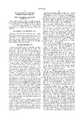
- FIG. 1is a schematic illustration of a typical cellular telephone wireless communication system
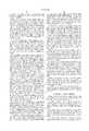
- FIG. 2is a pictorial representation of one embodiment of the present invention in the form of a cellular telephone
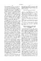
- FIG. 3provides a schematic functional block diagram of a portion of a wireless communication device embodying the present invention
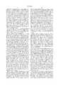
- FIGS. 4 and 5provide schematic functional block diagrams of parts of alternative embodiments of the present invention.
- FIG. 6provides a schematic functional block diagram of another alternative embodiment of the present invention.
- FIG. 7provides a schematic functional block diagram of an architecture for a core circuit portion of a single-chip or chip-set product which may be used to implement the present invention.
- FIG. 1schematically depicts a typical cellular communication system 10.
- the system 10is depicted to include three subscriber units 12 (which may be portable cell-phones, PPCD's, or PC's equipped to communicate over the cellular communication system depicted, for example), and three base stations 14.
- subscriber units 12which may be portable cell-phones, PPCD's, or PC's equipped to communicate over the cellular communication system depicted, for example
- base stations 14may include a large number of base stations, and a great number of subscriber units which are accessing or participating in the system at any one time.
- An alternative configuration of the inventionmay take the form of a private wireless communication system, such as would be used within the considerable confines of a large office building complex or manufacturing facility. The schematic representation of such a private wireless communication system would appear much the same as FIG. 1.
- the subscriber units 12can include mobile units such as hand-held portable telephones (i.e., the now-familiar cellular telephones), stationary units (such as desk top computers), and portable personal communication devices (PPCD's--such as palm-top computers equipped with radio-frequency modems and/or radio frequency facsimile devices).
- the system 10also includes a number of base stations 14 that allow the subscriber units 12 to communicate with each other and with other communication devices in other networks.
- the system 10covers a geographic area that is effectively divided into a grid or array of cell sites, with each cell site containing at least one base station 14.
- Each base station 14communicates with all subscriber units 12 within the area of its respective cell site via radio frequency ("RF") signals.
- RFradio frequency
- One frequencyis used for transmission from the base station 14 to the subscriber units 12 (the “downlink” frequency), and a different frequency is used for transmission from the subscriber units 12 to the base station 14 (the “uplink” frequency).
- the system 10employs "frequency reuse" to allow more than one base station 14 to operate at the same radio frequency.
- Each cell siteis made large enough in area so that RF signals originating in one cell site and crossing into an adjoining cell site are sufficiently attenuated by distance so that they are perceived as lower level background noise by base stations in the adjacent and more distant cell sites.
- Frequency isolationoccurs between adjacent cell sites by assigning these cells differing frequency band widths for their operations.
- RF signalsare inherently attenuated in proportion to the square of the distance from the radiating source.
- same-frequency signals from a distant cellare perceived merely as noise within a particular cell operating on that frequency. Isolation may also be furthered by interference arising from man-made structures and natural topological features.
- One or more frequency bandsare set aside for setting up a communication link or call between the base station 14 and a subscriber unit 12. Effectively, the system 10 provides a cellular communications environment within its service area for the subscribers using subscriber units 12.
- the base stations 14are interlinked with a network controller 16 via a distribution facility such as a dedicated copper wire or fiber optic network, a radio communication link, or a satellite link.
- the network controller 16provides access to existing communication networks 18.
- the existing communication network 18is depicted singularly as a telephone interface, but it will be understood that this is merely exemplary.
- the interface 18is multi-faceted (as is schematically indicated by the spray of double-ended arrows 20) and may provide communication with a variety of other analog and/or digital communication facilities and networks, such as computer data bases, the World Wide Web, satellite links, television satellite communication channels, LAN's, WAN's, main-frames, work-stations, personal computer systems, and other communication facilities.
- each base station 14determines the received signal strength of each call in progress, and forwards this information to the network controller 16.
- the network controller 16uses advanced processing technology to keep track of all calls between the subscriber units 12 and base stations 14. As the subscriber unit 12 moves within the cellular communication environment provided by system 10, the network controller 16 also uses the signal strength information received at each base station 14 from the particular subscriber units 12 to determine when a call should be "handed off" from a base station in one cell site to the base station in another cell site.
- Such hand-off of mobile subscriber units as they move from one cell site to the nextallows communication to be maintained with a subscriber unit 12 as the subscriber unit 12 moves from cell site to cell site within the environment system 10.
- some subscriber units 12may be stationary, so that hand-off of communications with these subscriber units is not necessary.
- FIG. 2depicts a cellular communication device 22 embodying the present invention.
- the device 22may take the form of an externally-typical cellular telephone. Because the cellular telephone externally appears to be the same as conventional cellular telephones, a detailed presentation of its operational features is not necessary.
- the cellular telephone 22includes a body 24 housing a battery (not shown) allowing mobile operations, and having a speaker 26, a microphone 28, and a keypad 30.
- a pivotal cover portion 32covers the microphone 28 and keypad 30 in its closed position (not shown) and functions as the switch hook for the cell-phone 22.
- a telescopic antenna 34provides for transmission and reception of radio frequency signals.
- the cellular telephone 22is self-adapting to various frequency bands and communication protocols which may be encountered in use.
- the cellular telephone 22is not merely a U.S. cell-phone, or a European cell-phone, or a cell phone with a limited service area, as is the case with conventional cellular telephones.
- the cell-phone 22 embodying the present inventionmay be considered a world cell-phone because it will function where ever the user of the device may choose to provide for a service agreement with local service providers. Understandably, this service provision agreement may be a single umbrella agreement encompassing several service areas; or may consist of many agreements, one in each of the various areas where a user of the cell phone wishes to travel and enjoy cell-phone use. The same is true if the device 22 is implemented in the form of a PPCD or as a PC, for example.
- FIG. 3a schematic diagram of a wireless cellular communication device 36 is presented.
- This device 36may take the form of the cellular telephone 22 seen in FIG. 2, or may take the form of any one of the other wireless communication devices discussed above.
- the device 36may be implemented as a subscriber unit 12 or base station 14 of the cellular system discussed in connection with FIG. 1.
- the device 36can be implemented as part of a wireless personal communication device, like a palm-top computer with an radio frequency fax/modem, for example, and which also provides audio cellular telephone communications.
- Such a communication devicecan also be implemented as part of a personal computer for stationary uses, if desired.
- the device 36is frequency agile, and is able to adapt itself to operate in varying cellular communication system environments, as well as in cellular systems having differing communication protocols.
- this facilityis of most immediate advantage with mobile equipment such as portable cell-phones and personal communication devices.
- less mobile equipmentsuch as PC's with wireless fax/modems, can also benefit because they can interface with local cellular communication systems wherever the purchaser of such a PC takes the computer, and without modification of the computer being required.
- the user of the computer, portable personal communication device, or portable cell-phoneneed not even be aware that the various geographic areas to which the user travels have differing cellular telephone frequency bands and differing communication protocols.
- the computer, cell-phone, or personal communication device implementing the inventionwill simply self-adapt to the local cellular communication system operating environment, and will provide communication with the user not detecting any external change in the device.
- the device 36includes a single integrated circuit chip 38, the encompassing boundary of which is delineated by a dashed line 38', and the semiconductor substrate of which is indicated with the numeral 38". While it is preferable that the structures and functions described below for chip 38 be located on a single integrated circuit chip, those ordinarily skilled in the pertinent arts will recognize that selected parts of the structure (and the associated functions) may be located on a second or additional integrated circuit chips. Accordingly, it will be recognized that the structures and functions depicted and described for circuit 38 may be located alternatively on a chip set rather than on a single integrated circuit chip.
- the chip 38provides a two-way interface (indicated by double-ended arrow 40) with external physical interface devices (indicated with block 42).
- these external physical interface devicesmay include a speaker 26, a microphone 28, and a keypad 30.
- the interface devicesmay include an interface with a fax/modem device (not shown), or with a personal computer data register or memory device (also not shown) allowing communication of digital data files.
- the chip 38also has an interface (indicated on FIGS. 3, 4, and 5 with the arrowed numerals 44) with an antenna (such as antenna 34, recalling the description of FIG. 2), via an intermediate frequency circuit 46, and radio frequency circuits 48a, 48b seen in FIG. 4 (or 48a, 48b, 48c, and 48d, in the embodiment of FIG. 5).
- a control interconnection 50(which will be further described below) is provided between the chip 38 and the various radio frequency sections seen in FIGS. 4 or 5.
- Arrowed numeral 52 seen in FIGS. 4 and 5indicates radio-frequency connections between the RF circuit sections indicated and the antenna 34, or another antenna.
- Chip circuit 38also has an interface (indicated by arrow 54) with an external memory facility 56.
- This external memory facility 56may take the form of a flash-memory card, or of a SIMM card memory.
- the memory 56is removable from the cell-phone or portable personal communication device in order to allow additional communication protocols and other data to be programmed into the device.
- the programming and storage of necessary data in the memory device 56may be added to or changed via the interface with the cellular communication system 10 described with reference to FIG. 1.
- a communication system protocolfor example, is needed in order for a cell-phone or PPCD to be functional in a particular cellular communication environment, it is downloaded from the system to the newly-arrived device. As soon as this downloading is completed, the device is operable in the particular cellular communication system environment.
- the user of the devicemay notice a delay after first turning the device on in the environment and it operability in this environment. This delay would be the only indication to a user of devices embodying the invention that the invention is present and operating. In other respects, the present invention is transparent to users of devices embodying the invention.
- a power sourcesuch as a battery--not shown
- control interfacessuch as the switch hook control switch described above with reference to the cell-phone of FIG. 2
- circuit 38Viewing the circuit architecture of FIG. 3, it is seen that the circuit chip 38 includes a micro-controller 58 (i.e., a programmable microprocessor) controlling operation of the chip 38 (and of the communication device 22).
- the micro-controller 58 and a digital signal processor (DSP) 60have an interface (indicated at 64) with the external physical interface devices 42 via the interface connection 40.
- DSP 60has associated with it a random access memory (RAM) facility 62.
- Micro-controller 58also has an interface via a RAM 66 with the external memory 56, as is indicated by arrowed connection 68.
- the micro-controller 58 and DSP 60are communicated with one another via a communication bus 70, which also provides communication with respective bi-directional branches of a communication protocol adaptation tree 72 (i.e., a portion of the circuit 38).
- a communication protocol adaptation tree 72i.e., a portion of the circuit 38.
- bi-directionalis meant that communication signals are passed in both directions along these adaptation tree branches.
- received communication signalsare passed from right to left along the appropriate one of the branches 72a, 72b from the RF portion for decoding to human-intelligible speech.
- speech communications from the user of the device 22are passed from left to right along the appropriate one of these branches for conversion into the particular format being used in the cellular communication environment in which the device 22 is being used at a particular time.
- the micro-controller 58can sample the communication environment by selective activation of the branches 72a and 72b, as well as by control of portions of the RF section 46, 48 to adapt the device 22 to the cellular communication environment.
- the adaptation tree 72is depicted as having only two branches 72a and 72b.
- the branch 72ahandles communications in GSM protocol
- branch 72bhandles communications in one of CDMA or TDMA protocols.
- the branch 72bcan handle either of these protocols in accord with a command from micro-controller 58.
- an alternative architecture for the circuit chip 38would be to provide a dedicated branch for each of the CDMA and TDMA protocols.
- each of the branches 72a and 72beach includes a respective detector/analog-to-digital converter (ADC) 74a, 74b for receiving communications signals from the RF circuits 46 and 48 (a, b, c, d) seen in FIGS. 4 and 5.
- the converters 74convert analog communication signals of a format corresponding to the communication system environment in which the device 22 is being used and received via the RF circuits to digital communication signals.
- a Viterbi equalizer 76receives the communication signals in digital format and passes them to a GSM cipher/decipher circuit portion 78.
- the GSM cipher/decipher circuit portion 78passes the signals via a GSM burst format converter 80 to a modulator digital-to-analog converter (DAC) 82 for conversion from digital form into analog form for handling in the RF section which is to be discussed in further detail below.
- DACdigital-to-analog converter
- the GSM cipher/decipher circuit portion 78passes communication signals with a GSM interleaving/de-interleaving circuit portion 84, which in turn passes communication signals with a GSM speech coder/decoder 86.
- the circuit portion 86has an interface via buss 70 with the DSP 60 so that the latter circuit can assist in such digital signal processing chores as are required in the branch 72a.
- the DSP 60passes the speech result of this process to and from the external interfaces 42 or receives such speech input from these interfaces (i.e., to or from the speaker 26 and microphone 28) after or for passage along the branch 72a when the communication device 22 is operating in GSM format.
- the branch 72bincludes a CDMA/TDMA equalizer 88 which receives communication signals in the appropriate protocol in digital format from the detector/analog-to-digital converter (ADC) 74b and passes them to a CDMA/TDMA cipher/decipher circuit portion 90.
- the CDMA/TDMA equalizer 88passes the signals to a modulator digital-to-analog converter (DAC) 92 for conversion from digital form into analog form for handling in the RF section which is to be discussed in further detail below.
- DACdigital-to-analog converter
- the CDMA/TDMA cipher/decipher circuit portion 90passes communication signals with a CDMA/TDMA interleaving/de-interleaving circuit portion 94, which in turn passes communication signals with a TDMA/CDMA speech coder/decoder 96.
- the circuit portion 96has an interface via bus 70 with the DSP 60 so that the latter circuit can assist in such digital signal processing chores as are required in the branch 72b.
- the DSP 60passes the speech result of this process to and from the external interfaces 42 or receives such speech input from these interfaces after or for passage along the branch 72b when the communication device 22 is operating in CDMA or TDMA protocol.
- the micro-controller 58has a control interface with the DSP 60 and with the adaptation tree branches 72a, and 72b. It was pointed out above that the micro-controller 58 had a control interface 50 with the RF section 46, 48. The significance and use of these control interfaces will become more apparent in view of the following.
- FIGS. 4 and 5Viewing first FIG. 4, it is seen that one alternative for the RF sections 46, 48 is to have an intermediate frequency (IF) section 46 passing the communication signals in analog form with the appropriate branch 72a, 72b of the adaptation tree 72. This IF section passes the communication signals (at an intermediate frequency) with the appropriate one of two RF sections 48a, 48b.
- RF section 48ais a controllably adaptable 800 MHz or 900 MHz transceiver.
- RF section 48bis a controllably adaptable 1800 MHz or 1900 MHz transceiver. The operating frequency of these transceiver sections is selected by the micro-controller 58 by control exercised over control interface 50, as will be further explained.
- FIG. 5depicts another alternative for the RF section 46, 48.
- IF section 46passing the communication signals in analog form with the appropriate branch 72a, 72b of the adaptation tree 72, and with the appropriate one of four RF sections 48a, 48b, 48c, and 48d.
- RF section 48ais a controllable 800 MHz transceiver
- RF section 48bis a controllable 900 MHz transceiver.
- RF section 48cis a controllable 1800 MHz transceiver
- RF section 48dis a controllable 1900 MHz transceiver.
- the one or more of these transceiver sections to be operable at a particular timeis selected by the micro-controller 58 by control exercised over control interface 50, as will be further explained.
- the micro-controller 58simply exercises control via the control connections 50, 98, and 98' to operate the RF section at the appropriate frequency for the environment, as well as to operate the one of adaptation branches 72a or 72b (i.e., GSM protocol or one of CDMA or TDMA protocol) which applies in the environment.
- the one of adaptation branches 72a or 72bi.e., GSM protocol or one of CDMA or TDMA protocol
- the user of the device 22takes it to another cellular communication system environment, when first turned on the device 22 will be inoperative just like a conventional cellular communication device which is incompatible with its operating environment.
- This environmental samplingtakes place by the micro-controller selecting a first protocol for adaptation tree 72, then cycling the RF section through the available frequencies. A second and successive protocols are selected with the RF section being cycled through the available frequencies until the combination of communication protocol and operating frequency is arrived at to detect the cellular communication system set up instructions which are provide by the down-links of the system. Ordinarily, this sorting and selection process will take place so quickly when the device 22 is first turned on in a new cellular communication system environment that the user will not notice the adaptation of the device to its environment. Provided that the user has a service account that is recognizable to the local cellular communication service system, then the device 22 will simple provide cellular communication system access with the user not having to worry or take notice of the differing system environments.
- Another advantage of the multi-frequency and multi-protocol capability of the device 22can be realized in cellular communication system environments which may allow simultaneous access via more than one operating frequency band or more than one protocol.
- the usercould use the device 22 to carry out simultaneous conference calls with several others, or to carry out simultaneous audio communication while a data transfer or video transfer is also taking place.
- This data or graphics file information transfer capability of the devicewill be understood in view of the disclosure of the co-pending application referenced above, and the following description of an alternative embodiment of the invention.
- FIG. 6an alternative embodiment of the invention is depicted.
- the embodiment of FIG. 6provides a portable personal communication device which is able to send and receive a wide variety of communication signals, as will be seen.
- the device 122includes external physical interfaces 142, an integrated circuit chip 138, an RF section 146/148, and an antenna 134.
- the chip 138(or chip set) includes a portion (or separate chip of a chip set) which is indicated with the numeral 200.
- the chip circuit portion 200is a portion of the chip 138 (i.e., is formed on the same semiconductor material substrate) so that hereinafter, portion 200 is referred to as though it is understood that it is a part of chip 138.
- the chip 38may be a basic chip used in devices of basic capability, while the addition of the chip 200 provides a device of more advanced capability. This building block approach to adding capability of a communication device 22 (or 122) will be more fully understood after a consideration of a core architecture for the chips 38 and/or 138, which is discussed below.
- sources of communication signals for video, audio and dataare not limited to other mobile and stationary subscriber units 12 in the system 10. Since the base stations 14 are linked to telephone networks, data can be provided over wired networks by sources such as private facsimile machines and corporate computers containing private or commercial databases. Audio can be provided over wired networks by analog telephones, personal computers and even radios. Video and graphics files can be provided by direct broadcast satellites and Very Small Aperture Terminals (VSAT), and by computers over fiber optic and ISDN networks. Internet and world wide web access via various ones of these connection possibilities make a great variety of communication signal sources and types available to the user of the device 122.
- VSATVery Small Aperture Terminals
- the circuit portion 138provides the possibility for the device 122 to recognize and self adapt also to a wide variety of high speed communication signals formats and protocols, including present and future formats for video and graphics images, as well as high-speed data transmission.
- the circuit portion 200shares a signal communication connection with micro-controller 58 and DSP 60 (recalling the description above of chip 38). This connection is by interface with the buss 70.
- arrowed numeral 204indicates a shared connection with control interconnection 98/98'.
- the circuit portion 200includes its own micro-controller 206 with micro-controller RAM 208, as well as its own DSP 210 with DSP RAM 212.
- micro-controller function and DSP functionare considered to be resident in the circuit portions indicated with numerals 206 and 210, respectively.
- the interface with circuit portion 138allows circuit 200 to participate in sorting and recognizing various types, formats, and protocols of communication signals which may be received or transmitted by the device 122.
- the device 122can sort using the facilities explained below to identify and decode various video, graphics, data, and other present and future communication standards and formats. This self-adaptation of the device 122 allows it then to communicate in both directions using those signal types as may be present in the cellular wireless communication environment in which the user and device 122 find themselves.
- the circuit portion 200includes a adaptation branch 214a which is primarily for graphics and video image communication signals, and an adaptation branch 214b which is primarily for high speed data transmissions.
- this branchincludes a circuit portion 216 for compression and decompression of image signals according to the motion picture experts group (MPEG) MPEG1 protocol.
- a circuit portion 218allows compression/decompression of image signals according to MPEG2 protocol, while a portion 220 compresses and decompresses according to MPEG4 (which is also known as Wavelet).
- MPEG4which is also known as Wavelet
- the circuit portion 200also includes a general purpose microprocessor portion 222 with RAM 224.
- This processorcan be used to recognize, compress, and decompress signals according to future standards and protocols.
- Programming of the RAM to facilitate operation of the processor 222can be effected by hard-wired interconnection of the device 122 to a programming computer system, or may be effected by the user receiving programming over the wireless communication link, either automatically when an unfamiliar protocol or standard is encountered in the wireless communication environment, or by the user using the PPCD to request that the protocol or standard be downloaded from the system.
- circuit portion 226provides for compression and decompression, or coding and decoding, in wireless communication system data transfer protocols.
- circuit portions 228, 230, and 232provide for compression and decompression, or coding and decoding of data in fiber channel, serial link (i.e., QAM, QPSK), and Firewire protocols or standards, respectively.
- the device 122can use the same frequency and protocol or standard sorting methodology explained above to identify and communication in various protocols and standards as are available in the wireless communication environment as it exists at the present and as it may exist in the future.
- the user of the PPCD 122will be able to travel virtually throughout the world, while being able to access the wireless communication environment as it exists in the various geographic areas, and with a single device. That is, the contemporary requirement to purchase a number of cellular telephones or a number of PPCD's in order to achieve access to the wireless communication systems throughout the world is virtually eliminated by the present invention.
- FIG. 7a core circuit portion 234 for the circuits 38, and 138 is depicted.
- the core circuit portion 234includes an interface 340 to the external physical interface devices 342.
- the interface devices 340include a ADC,DAC device 340a for converting between analog signals to and from speaker 326 and microphone 328, and the digital signal processing facilities of the core circuit portion 234.
- the core circuit portion 234includes a one-way signal-receiving adaptation branch 372Rx, and a one-way signal-transmitting adaptation branch 372Tx. The directions of signal travel in each of these adaptation branches is indicated by the arrow associated with each.
- the branches 372are able to be altered by control and participation of the micro-controller 358 and DSP 360 (along with other circuit portions to be described) to perform all of the various functions of the several two-way adaptation branches described above with respect to circuit portions 38, 138, and 200.
- the core circuit portion 234includes a base-band ADC/DAC converter, indicated with numeral 236 for providing conversion of analog signals from the RF section to digital signals, and for providing analog signals to the RF section from the core circuit portion 234.
- the receiving adaptation branch 372Rxit is seen to include a Viterbi equalizer 376, feeding communication signals to deciphering and de-interleaving circuit portions 238 and 240, respectively.
- the de-interleaved received communication signalsare fed to a Viterbi decoder 242, and thence to a speech decoder 244.
- the physical interface 340athen provides analog speech signals to the speaker 326 based on the decoded digital speech signals provided by the decoder 246.
- the core circuit portion 234includes an interface driver 246 providing signals from such external physical interface devices as the keypad 30 and other inputs, to a fax/modem 248.
- a data codec 250provides an interface into a channel coder 252. Downstream of the channel coder (that is, in the direction of signal movement in branch 372Tx, as is indicated by the associated arrow), the circuit portions 254, and 256, respectively for interleaving and ciphering, will be familiar from the description above of FIG. 3.
- a speech segmenter 258 and speech coder 260are provided.
- the core circuit portion 234includes a micro-controller 358 and DSP 360, which function in the capacity of controllers 58 and 206, and as DSP's 60 and 210.
- the DSP 360is associated with a Viterbi accelerator 262.
- an internal memory 264fulfills the functions of memories 58, 60, 208, and 212 discussed above.
- a memory management and decompression circuit portion 266assists in achieving this memory facility. In order to achieve the RF section control indicated earlier by control interface 50 (and indicated on FIG.
- the core circuit portion 234includes an RF controller 268, which is effective to control interrupts to the power supplied to the RF sections (48a-d, for example), as well as to control frequency, power, and synchronization between the RF section and the cellular communication system (recalling the description above of uses of uplink and downlink frequencies to facilitate communication between the base stations and the subscriber units).
- core circuit portion 234also includes a SIMM interface circuit 270 and a display and keyboard driver 272.
- a power and clock management interface 274provides power and time management functions for the core circuit portion, and for associated circuit portions of a chip or chip set including the core portion 234.
- the core circuit portion 234 depicted in FIG. 7provides a foundational structure upon which an adaptive wireless communication device can be built using the teachings brought out above in the context of the descriptions of FIGS. 3-6.
- the core circuit portion 234is very efficient in terms of its device count and substrate area requirements, thus facilitating the formation of a single-chip product (most desirably), or of a chip-set product having an economical fabrication cost.
Landscapes
- Engineering & Computer Science (AREA)
- Computer Networks & Wireless Communication (AREA)
- Signal Processing (AREA)
- Mobile Radio Communication Systems (AREA)
- Transceivers (AREA)
Abstract
Description
Claims (4)
Priority Applications (3)
| Application Number | Priority Date | Filing Date | Title |
|---|---|---|---|
| US08/691,554US6035212A (en) | 1996-08-02 | 1996-08-02 | Multi-frequency wireless communication device |
| EP97303669AEP0823789A3 (en) | 1996-08-02 | 1997-06-02 | Multi-frequency wireless communication device |
| JP16755597AJP4237279B2 (en) | 1996-08-02 | 1997-06-24 | Multi-frequency wireless communication device |
Applications Claiming Priority (1)
| Application Number | Priority Date | Filing Date | Title |
|---|---|---|---|
| US08/691,554US6035212A (en) | 1996-08-02 | 1996-08-02 | Multi-frequency wireless communication device |
Publications (1)
| Publication Number | Publication Date |
|---|---|
| US6035212Atrue US6035212A (en) | 2000-03-07 |
Family
ID=24777001
Family Applications (1)
| Application Number | Title | Priority Date | Filing Date |
|---|---|---|---|
| US08/691,554Expired - LifetimeUS6035212A (en) | 1996-08-02 | 1996-08-02 | Multi-frequency wireless communication device |
Country Status (3)
| Country | Link |
|---|---|
| US (1) | US6035212A (en) |
| EP (1) | EP0823789A3 (en) |
| JP (1) | JP4237279B2 (en) |
Cited By (55)
| Publication number | Priority date | Publication date | Assignee | Title |
|---|---|---|---|---|
| WO2000067498A1 (en)* | 1999-05-03 | 2000-11-09 | Nokia Mobile Phones Limited | Asymmetric data transmission for use in a multi-modulation environment |
| US6173189B1 (en)* | 1998-12-18 | 2001-01-09 | Motorola, Inc. | Method and apparatus for multi-protocol reverse channel infrastructure sharing |
| US20010026630A1 (en)* | 2000-03-28 | 2001-10-04 | Yoshizou Honda | Moving image reception quality evaluation apparatus |
| US6320612B1 (en)* | 1998-05-12 | 2001-11-20 | Jan J. Young | Vehicular camera system with plural perspectives |
| US20020042287A1 (en)* | 2000-10-11 | 2002-04-11 | Kousuke Asami | Cellular phone |
| US20020118662A1 (en)* | 2001-02-28 | 2002-08-29 | Arnold Sheynman | Mobile station architectures for circuit and packet modes and methods therefor |
| US20020132636A1 (en)* | 2001-03-15 | 2002-09-19 | Dirk Stockhusen | Control of a multi-mode, multi-band mobile telephone via a single hardware and software man machine interface |
| US6484029B2 (en)* | 1998-10-13 | 2002-11-19 | Symbol Technologies, Inc. | Apparatus and methods for adapting mobile unit to wireless LAN |
| US20020176386A1 (en)* | 2001-03-22 | 2002-11-28 | Gurpreet Singh | Software for installation and configuration management of network nodes |
| US6515581B1 (en)* | 2001-08-10 | 2003-02-04 | Photic Electronics Co., Ltd. | Wireless vehicle reversal monitoring device |
| US6535499B1 (en)* | 1998-02-27 | 2003-03-18 | Fujitsu Limited | Multi-mode communication device |
| US20030072421A1 (en)* | 2001-10-12 | 2003-04-17 | Nec Corporation | Information terminal apparatus, communications method, and storage medium storing program therefor |
| US20030080189A1 (en)* | 2001-10-26 | 2003-05-01 | Symbol Technologies, Inc. | Bar code reader including linear sensor array and hybrid camera and bar code reader |
| US6671700B1 (en)* | 2000-05-23 | 2003-12-30 | Palm Source, Inc. | Method and apparatus for parallel execution of conduits during simultaneous synchronization of databases |
| US6684062B1 (en)* | 2000-10-25 | 2004-01-27 | Eleven Engineering Incorporated | Wireless game control system |
| WO2003100572A3 (en)* | 2002-05-24 | 2004-04-15 | Chrysalis Dev | Method and apparatus for detecting the presence of wireless network |
| US20040082383A1 (en)* | 2002-10-24 | 2004-04-29 | Motorola, Inc | Methodology and wireless device for interactive gaming |
| US6748246B1 (en) | 2000-07-05 | 2004-06-08 | Telefonaktiebolaget Lm Ericsson (Publ) | Method and apparatus for selecting an access technology in a multi-mode terminal |
| US20040160940A1 (en)* | 2003-02-13 | 2004-08-19 | Samsung Electronics Co., Ltd. | Digital signal processing apparatus of communication terminal for adaptably transmitting voice data to allotted uplink channels and voice data transmission method thereof |
| US20050032516A1 (en)* | 2002-05-24 | 2005-02-10 | Bruno Marchevsky | Method and apparatus for detecting the presence of a wireless network |
| US20050037738A1 (en)* | 2003-06-18 | 2005-02-17 | Keisuke Nakaya | Mobile communication terminal |
| US20050041621A1 (en)* | 2003-08-21 | 2005-02-24 | Dominique Gauthier | Method and system of handoff |
| US20050054379A1 (en)* | 1999-11-23 | 2005-03-10 | Qinghong Cao | Cordless telephone with MP3 player capability |
| US20050113031A1 (en)* | 2003-06-11 | 2005-05-26 | Kensington Technology Group | Systems and methods for a wireless network connection point locator |
| US20050144296A1 (en)* | 2000-11-17 | 2005-06-30 | Monroe David A. | Method and apparatus for distributing digitized streaming video over a network |
| US20050272464A1 (en)* | 2004-06-04 | 2005-12-08 | Takashi Ishikawa | Wireless communication device having wireless module compatible with wireless communication system |
| US20060030306A1 (en)* | 2000-12-07 | 2006-02-09 | Kuhn Brian G | Generic activation and registration framework for wireless devices |
| US20060128425A1 (en)* | 2004-12-13 | 2006-06-15 | Rooyen Pieter V | Method and system for mobile architecture supporting cellular or wireless networks and broadcast utilizing a multichip cellular and broadcast silicon solution |
| WO2005062815A3 (en)* | 2003-12-19 | 2006-10-12 | Gentex Corp | Device with improved serial communication |
| US20070032265A1 (en)* | 2005-08-02 | 2007-02-08 | Lg Electronics Inc. | Communication system, method, and dual mode terminal having a communication module controlled by message |
| US7206849B1 (en) | 1998-10-05 | 2007-04-17 | Symbol Technologies, Inc. | Communication in a wireless communications network when a mobile computer terminal may be unreachable |
| US20070109594A1 (en)* | 2003-01-03 | 2007-05-17 | E-Watch Inc. | Apparatus for Capturing, Converting and Transmitting a Visual Image Signal Via A Digital Transmission System |
| US20070117580A1 (en)* | 2005-11-11 | 2007-05-24 | Sennheiser Electronic Gmbh & Co. Kg | Method for allocating a frequency for a wireless audio communication |
| US20070121562A1 (en)* | 2005-11-25 | 2007-05-31 | Inventec Appliances Corp. | Communication control system and method thereof |
| US20070133711A1 (en)* | 2005-12-09 | 2007-06-14 | Weidong Li | Transmission interface module for digital and continuous-waveform transmission signals |
| US20070165583A1 (en)* | 2006-01-18 | 2007-07-19 | Research In Motion Limited | Methods and apparatus for use in switching communication operations between a wireless wide area network and a wireless local area network |
| US20070184805A1 (en)* | 2006-01-30 | 2007-08-09 | Research In Motion Limited | Portable audio device having reduced sensitivity to RF interference and related methods |
| US20070203844A1 (en)* | 2001-05-08 | 2007-08-30 | Palm, Inc. | Activation key for a wireless-enabled device |
| US20080043868A1 (en)* | 2005-08-03 | 2008-02-21 | Kamilo Feher | Internet GSM, CDMA, OFDM, Wi-Fi wireless and wired multimode systems |
| US7359516B1 (en)* | 2000-12-07 | 2008-04-15 | Palmsource, Inc. | User interface technique for selection and activation of wireless services from among multiple transport carriers |
| US20080214231A1 (en)* | 2000-03-22 | 2008-09-04 | Mlr, Llc | Tiered Wireless, Multi-Modal Access System and Method |
| US20080274767A1 (en)* | 1993-12-15 | 2008-11-06 | Mlr, Llc | Adaptive Omni-Modal Radio Apparatus and Methods |
| US20090061852A1 (en)* | 2005-08-03 | 2009-03-05 | Kamilo Feher | Automobile wireless door opener and ignition starter by cellular device |
| US20100022240A1 (en)* | 2001-01-05 | 2010-01-28 | Palm, Inc. | Requesting a user account for services |
| US20100208852A1 (en)* | 2005-08-03 | 2010-08-19 | Kamilo Feher | Cascaded 4G, 3G, 2G and other systems |
| US7929950B1 (en)* | 1996-12-16 | 2011-04-19 | Ip Holdings, Inc. | Dynamically configurable IP based wireless device and wireless networks |
| USRE42697E1 (en) | 1993-12-15 | 2011-09-13 | Mlr, Llc. | Apparatus and methods for networking omni-modal radio devices |
| US8077735B1 (en) | 2002-02-26 | 2011-12-13 | Unruh Lincoln J | System and method for reliable communications over multiple packet RF networks |
| US8259832B2 (en) | 1999-08-09 | 2012-09-04 | Kamilo Feher | QAM and GMSK modulation methods |
| US8565107B2 (en) | 2010-09-24 | 2013-10-22 | Hand Held Products, Inc. | Terminal configurable for use within an unknown regulatory domain |
| US8958846B2 (en) | 1999-09-02 | 2015-02-17 | Charles Freeny, III | Communication and proximity authorization systems |
| US9307407B1 (en) | 1999-08-09 | 2016-04-05 | Kamilo Feher | DNA and fingerprint authentication of mobile devices |
| US9373251B2 (en) | 1999-08-09 | 2016-06-21 | Kamilo Feher | Base station devices and automobile wireless communication systems |
| US9813270B2 (en) | 1999-08-09 | 2017-11-07 | Kamilo Feher | Heart rate sensor and medical diagnostics wireless devices |
| US10009956B1 (en) | 2017-09-02 | 2018-06-26 | Kamilo Feher | OFDM, 3G and 4G cellular multimode systems and wireless mobile networks |
Families Citing this family (12)
| Publication number | Priority date | Publication date | Assignee | Title |
|---|---|---|---|---|
| JPH11285066A (en)* | 1998-03-27 | 1999-10-15 | Kokusai Electric Co Ltd | Mobile communication device |
| DE69827381T2 (en)* | 1998-08-12 | 2005-03-17 | Siemens Ag | Multimode telecommunication device for channel selection |
| EP1650865B1 (en) | 1998-10-27 | 2009-10-21 | Murata Manufacturing Co., Ltd. | Composite high frequency component and mobile communication device including the same |
| FI112741B (en) | 1998-11-26 | 2003-12-31 | Nokia Corp | Method and apparatus for transmitting and receiving RF signals at various radio interfaces of data transmission systems |
| JP3910764B2 (en)* | 1999-08-18 | 2007-04-25 | 株式会社東芝 | Mobile radio terminal device |
| EP1091537A1 (en)* | 1999-10-08 | 2001-04-11 | Siemens Aktiengesellschaft | Method for sending data of over a packet-switched radio network and a method for receiving data over a packet-switched radio network |
| FR2808401B1 (en) | 2000-04-26 | 2002-06-28 | Sagem | COMMUNICATION METHOD BETWEEN TWO MULTIMODE RADIO TERMINALS AND TERMINAL FOR IMPLEMENTING THE METHOD |
| US6665284B1 (en) | 2000-07-31 | 2003-12-16 | Nokia Mobile Phones, Ltd. | Apparatus, and associated method, for receiving data at a radio device |
| GB2383700A (en)* | 2001-09-27 | 2003-07-02 | Inquam | Frequency converter for CDMA systems |
| CN1675950A (en)* | 2002-08-10 | 2005-09-28 | 皇家飞利浦电子股份有限公司 | Method of increasing the data transmission rate in a mobile radio system |
| JP4719492B2 (en)* | 2005-03-28 | 2011-07-06 | 富士通東芝モバイルコミュニケーションズ株式会社 | Mobile radio terminal device |
| US20070071006A1 (en)* | 2005-09-26 | 2007-03-29 | Peter Bosch | Delivery of communications services in developing regions |
Citations (4)
| Publication number | Priority date | Publication date | Assignee | Title |
|---|---|---|---|---|
| US5127042A (en)* | 1988-09-23 | 1992-06-30 | Motorola, Inc. | Cellular cordless telephone |
| US5210785A (en)* | 1988-02-29 | 1993-05-11 | Canon Kabushiki Kaisha | Wireless communication system |
| US5493693A (en)* | 1990-07-09 | 1996-02-20 | Kabushiki Kaisha Toshiba | Mobile radio communication system utilizing mode designation |
| US5732348A (en)* | 1994-04-28 | 1998-03-24 | Nec Corporation | Cellular telephone set capable of automatically selecting a control channel without switching operational modes from one to another |
Family Cites Families (3)
| Publication number | Priority date | Publication date | Assignee | Title |
|---|---|---|---|---|
| ATE532370T1 (en)* | 1993-12-15 | 2011-11-15 | Mlr Llc | WIRELESS COMMUNICATION SYSTEM WITH A VARIETY OF INDEPENDENT WIRELESS SERVICE NETWORK |
| AUPM414394A0 (en)* | 1994-02-28 | 1994-03-24 | Voxson International Pty. Limited | Multi-mode communications system |
| US5475677A (en)* | 1994-12-29 | 1995-12-12 | Bell Communications Research Inc. | Compatible licensed and unlicensed band portable handset unit for TDMA wireless communications system |
- 1996
- 1996-08-02USUS08/691,554patent/US6035212A/ennot_activeExpired - Lifetime
- 1997
- 1997-06-02EPEP97303669Apatent/EP0823789A3/ennot_activeWithdrawn
- 1997-06-24JPJP16755597Apatent/JP4237279B2/ennot_activeExpired - Lifetime
Patent Citations (4)
| Publication number | Priority date | Publication date | Assignee | Title |
|---|---|---|---|---|
| US5210785A (en)* | 1988-02-29 | 1993-05-11 | Canon Kabushiki Kaisha | Wireless communication system |
| US5127042A (en)* | 1988-09-23 | 1992-06-30 | Motorola, Inc. | Cellular cordless telephone |
| US5493693A (en)* | 1990-07-09 | 1996-02-20 | Kabushiki Kaisha Toshiba | Mobile radio communication system utilizing mode designation |
| US5732348A (en)* | 1994-04-28 | 1998-03-24 | Nec Corporation | Cellular telephone set capable of automatically selecting a control channel without switching operational modes from one to another |
Cited By (182)
| Publication number | Priority date | Publication date | Assignee | Title |
|---|---|---|---|---|
| US7738865B2 (en) | 1989-06-29 | 2010-06-15 | Symbol Technologies, Inc. | Apparatus and method for wireless local area networks of different countries |
| USRE42697E1 (en) | 1993-12-15 | 2011-09-13 | Mlr, Llc. | Apparatus and methods for networking omni-modal radio devices |
| US20080274767A1 (en)* | 1993-12-15 | 2008-11-06 | Mlr, Llc | Adaptive Omni-Modal Radio Apparatus and Methods |
| US7929950B1 (en)* | 1996-12-16 | 2011-04-19 | Ip Holdings, Inc. | Dynamically configurable IP based wireless device and wireless networks |
| US20140187231A1 (en)* | 1996-12-16 | 2014-07-03 | Ip Holdings, Inc. | Dynamically Configurable Mobile Device, Cellular Phones, and Wireless Networks |
| US8442501B1 (en) | 1996-12-16 | 2013-05-14 | Ip Holdings, Inc. | Dynamically configurable IP based wireless devices and networks |
| US8447289B2 (en) | 1996-12-16 | 2013-05-21 | Ip Holdings, Inc. | Dynamically configurable wireless device and server communication system |
| US8472937B1 (en) | 1996-12-16 | 2013-06-25 | Ip Holdings, Inc. | Dynamically configurable IP based mobile devices and networks |
| US9049119B2 (en)* | 1996-12-16 | 2015-06-02 | Ip Holdings, Inc. | Dynamically configurable mobile device and cellular phones with functions |
| US8472936B1 (en) | 1996-12-16 | 2013-06-25 | Ip Holdings, Inc. | Dynamically configurable IP based wireless devices and wireless networks |
| US8472927B1 (en) | 1996-12-16 | 2013-06-25 | Ip Holdings, Inc. | Dynamically configurable mobile device, cellular phones, and wireless networks |
| US6535499B1 (en)* | 1998-02-27 | 2003-03-18 | Fujitsu Limited | Multi-mode communication device |
| US6320612B1 (en)* | 1998-05-12 | 2001-11-20 | Jan J. Young | Vehicular camera system with plural perspectives |
| US8693523B2 (en) | 1998-08-10 | 2014-04-08 | Kamilo Feher | QAM CDMA and TDMA communication methods |
| US7206849B1 (en) | 1998-10-05 | 2007-04-17 | Symbol Technologies, Inc. | Communication in a wireless communications network when a mobile computer terminal may be unreachable |
| US6484029B2 (en)* | 1998-10-13 | 2002-11-19 | Symbol Technologies, Inc. | Apparatus and methods for adapting mobile unit to wireless LAN |
| US7260395B1 (en) | 1998-10-13 | 2007-08-21 | Symbol Technologies, Inc. | Apparatus and method for wireless local area networks of different countries |
| US6173189B1 (en)* | 1998-12-18 | 2001-01-09 | Motorola, Inc. | Method and apparatus for multi-protocol reverse channel infrastructure sharing |
| WO2000067498A1 (en)* | 1999-05-03 | 2000-11-09 | Nokia Mobile Phones Limited | Asymmetric data transmission for use in a multi-modulation environment |
| US6377817B1 (en) | 1999-05-03 | 2002-04-23 | Nokia Mobile Phones Ltd. | Asymmetric data transmission for use in a multi-modulation environment |
| US9049985B2 (en) | 1999-08-09 | 2015-06-09 | Kamilo Feher | Satellite, cellular and Wi-Fi mobile multimode transmission and reception methods |
| US9397724B1 (en) | 1999-08-09 | 2016-07-19 | Kamilo Feher | Transceivers digital mobile communications |
| US9571626B1 (en) | 1999-08-09 | 2017-02-14 | Kamilo Feher | Automobile cellular, WLAN and satellite communications |
| US8259832B2 (en) | 1999-08-09 | 2012-09-04 | Kamilo Feher | QAM and GMSK modulation methods |
| US9537700B2 (en) | 1999-08-09 | 2017-01-03 | Kamilo Feher | Mobile networks and mobile repeaters |
| US9742605B2 (en) | 1999-08-09 | 2017-08-22 | Kamilo Feher | OFDM mobile networks |
| US9432152B2 (en) | 1999-08-09 | 2016-08-30 | Kamilo Feher | Video multimode multimedia data communication systems |
| US9307407B1 (en) | 1999-08-09 | 2016-04-05 | Kamilo Feher | DNA and fingerprint authentication of mobile devices |
| US9373251B2 (en) | 1999-08-09 | 2016-06-21 | Kamilo Feher | Base station devices and automobile wireless communication systems |
| US9755874B2 (en) | 1999-08-09 | 2017-09-05 | Kamilo Feher | Digital mobile communication |
| US9755693B2 (en) | 1999-08-09 | 2017-09-05 | Kamilo Feher | Remote controlled (RC) air based communication |
| US9813270B2 (en) | 1999-08-09 | 2017-11-07 | Kamilo Feher | Heart rate sensor and medical diagnostics wireless devices |
| US9319212B2 (en) | 1999-08-09 | 2016-04-19 | Kamilo Feher | Fingerprint authenticated touchsceeen contolled cascaded 3G-OFDM mobile systems |
| US9264877B2 (en) | 1999-08-09 | 2016-02-16 | Kamilo Feher | Modems for mobile internet and cellular systems |
| US9173566B2 (en) | 1999-08-09 | 2015-11-03 | Kamilo Feher | DNA, blood, heart, glucose, body temperature, skin and other medical diagnostic communications |
| US8958846B2 (en) | 1999-09-02 | 2015-02-17 | Charles Freeny, III | Communication and proximity authorization systems |
| US20100144389A1 (en)* | 1999-11-23 | 2010-06-10 | Agere Systems Inc. | Cordless telephone with mp3 player capability |
| US7702363B2 (en) | 1999-11-23 | 2010-04-20 | Agere Systems Inc. | Cordless telephone with MP3 player capability |
| US8200280B2 (en) | 1999-11-23 | 2012-06-12 | Agere Systems Inc. | Cordless telephone with digital audio player capability |
| US20050054379A1 (en)* | 1999-11-23 | 2005-03-10 | Qinghong Cao | Cordless telephone with MP3 player capability |
| US20110201384A1 (en)* | 1999-11-23 | 2011-08-18 | Agere Systems Inc. | Cordless Telephone with Digital Audio Player Capability |
| US7945285B2 (en) | 1999-11-23 | 2011-05-17 | Agere Systems Inc. | Integrating a digital encoded-audio bit stream player in a radio-frequency telephone handset |
| US7945284B1 (en)* | 1999-11-23 | 2011-05-17 | Agere Systems Inc. | Cordless telephone with MP3 player capability |
| US7627340B2 (en)* | 2000-03-22 | 2009-12-01 | Mlr, Llc | Tiered wireless, multi-modal access system and method |
| US20080214231A1 (en)* | 2000-03-22 | 2008-09-04 | Mlr, Llc | Tiered Wireless, Multi-Modal Access System and Method |
| US9532267B2 (en) | 2000-03-22 | 2016-12-27 | Mobile Data Off-Loading Inc. | Tiered wireless, multi-modal access system and method |
| US10098047B2 (en) | 2000-03-22 | 2018-10-09 | Mobile Data Off-Loading, Inc. | Tiered wireless, multi-modal access system and method |
| US20010026630A1 (en)* | 2000-03-28 | 2001-10-04 | Yoshizou Honda | Moving image reception quality evaluation apparatus |
| US6671700B1 (en)* | 2000-05-23 | 2003-12-30 | Palm Source, Inc. | Method and apparatus for parallel execution of conduits during simultaneous synchronization of databases |
| US6748246B1 (en) | 2000-07-05 | 2004-06-08 | Telefonaktiebolaget Lm Ericsson (Publ) | Method and apparatus for selecting an access technology in a multi-mode terminal |
| US20020042287A1 (en)* | 2000-10-11 | 2002-04-11 | Kousuke Asami | Cellular phone |
| US6684062B1 (en)* | 2000-10-25 | 2004-01-27 | Eleven Engineering Incorporated | Wireless game control system |
| US7698450B2 (en) | 2000-11-17 | 2010-04-13 | Monroe David A | Method and apparatus for distributing digitized streaming video over a network |
| US20050144296A1 (en)* | 2000-11-17 | 2005-06-30 | Monroe David A. | Method and apparatus for distributing digitized streaming video over a network |
| US9332079B2 (en)* | 2000-12-07 | 2016-05-03 | Qualcomm Incorporated | Generic activation and registration framework for wireless devices |
| US20060030306A1 (en)* | 2000-12-07 | 2006-02-09 | Kuhn Brian G | Generic activation and registration framework for wireless devices |
| US20090005039A1 (en)* | 2000-12-07 | 2009-01-01 | Palm, Inc. | Providing user interface data on a mobile computing device |
| US7359516B1 (en)* | 2000-12-07 | 2008-04-15 | Palmsource, Inc. | User interface technique for selection and activation of wireless services from among multiple transport carriers |
| US8144873B2 (en) | 2000-12-07 | 2012-03-27 | Access Co., Ltd. | User interface technique for selection and activation of wireless service among multiple transport carriers |
| US20080003994A1 (en)* | 2000-12-07 | 2008-01-03 | Palm, Inc. | Generic Activation and Registration Framework for Wireless Devices |
| US7894847B2 (en) | 2000-12-07 | 2011-02-22 | Palm, Inc. | Activation of mobile computing device |
| US20100120407A1 (en)* | 2000-12-07 | 2010-05-13 | Palm, Inc. | User registration for wireless service on mobile computing device |
| US8918100B2 (en) | 2000-12-07 | 2014-12-23 | Qualcomm Incorporated | Providing user interface data on a mobile computing device |
| US20100120428A1 (en)* | 2000-12-07 | 2010-05-13 | Palm, Inc. | Wireless services over different carrier networks |
| US20070178899A1 (en)* | 2000-12-07 | 2007-08-02 | Palm, Inc. | Mobile device capable of registering with multiple servers |
| US8744441B2 (en) | 2000-12-07 | 2014-06-03 | Qualcomm Incorporated | Wireless services over different carrier networks |
| US20080176550A1 (en)* | 2000-12-07 | 2008-07-24 | Palmsource, Inc. | User interface technique for selection and activation of wireless services from among multiple transport carriers |
| US20100022240A1 (en)* | 2001-01-05 | 2010-01-28 | Palm, Inc. | Requesting a user account for services |
| US7861009B2 (en) | 2001-01-05 | 2010-12-28 | Palm, Inc. | Requesting a user account for services |
| US20110149861A1 (en)* | 2001-01-05 | 2011-06-23 | Palm, Inc. | Activation of mobile computing device on a cellular network |
| US8131888B2 (en) | 2001-01-05 | 2012-03-06 | Hewlett-Packard Development Company, L.P. | Activation of mobile computing device on a cellular network |
| US7706336B2 (en)* | 2001-02-28 | 2010-04-27 | Motorola, Inc. | Mobile station architectures for circuit and packet modes and methods therefor |
| US20020118662A1 (en)* | 2001-02-28 | 2002-08-29 | Arnold Sheynman | Mobile station architectures for circuit and packet modes and methods therefor |
| US7181237B2 (en)* | 2001-03-15 | 2007-02-20 | Siemens Communications, Inc. | Control of a multi-mode, multi-band mobile telephone via a single hardware and software man machine interface |
| US20020132636A1 (en)* | 2001-03-15 | 2002-09-19 | Dirk Stockhusen | Control of a multi-mode, multi-band mobile telephone via a single hardware and software man machine interface |
| US20020176386A1 (en)* | 2001-03-22 | 2002-11-28 | Gurpreet Singh | Software for installation and configuration management of network nodes |
| US6985461B2 (en) | 2001-03-22 | 2006-01-10 | Symbol Technologies, Inc. | Software for installation and configuration management of network nodes |
| US8036991B2 (en) | 2001-05-08 | 2011-10-11 | Hewlett-Packard Development Company, L.P. | Registration of a mobile computing device for a service on a wireless network |
| US20100169217A1 (en)* | 2001-05-08 | 2010-07-01 | Palm, Inc. | Registration of a mobile computing device for a service on a wireless network |
| US20100165938A1 (en)* | 2001-05-08 | 2010-07-01 | Palm, Inc. | Registration of a mobile computing device for a data service on a wireless network |
| US20070203844A1 (en)* | 2001-05-08 | 2007-08-30 | Palm, Inc. | Activation key for a wireless-enabled device |
| US8812398B2 (en) | 2001-05-08 | 2014-08-19 | Qualcomm Incorporated | Key for a wireless-enabled device |
| US9524497B2 (en) | 2001-05-08 | 2016-12-20 | Qualcomm Incorporated | Registration of a mobile computing device for a data service on a wireless network |
| US6515581B1 (en)* | 2001-08-10 | 2003-02-04 | Photic Electronics Co., Ltd. | Wireless vehicle reversal monitoring device |
| US20030072421A1 (en)* | 2001-10-12 | 2003-04-17 | Nec Corporation | Information terminal apparatus, communications method, and storage medium storing program therefor |
| US7040538B2 (en) | 2001-10-26 | 2006-05-09 | Symbol Technologies, Inc. | Bar code reader including linear sensor array and hybrid camera and bar code reader |
| US20030080189A1 (en)* | 2001-10-26 | 2003-05-01 | Symbol Technologies, Inc. | Bar code reader including linear sensor array and hybrid camera and bar code reader |
| US8077735B1 (en) | 2002-02-26 | 2011-12-13 | Unruh Lincoln J | System and method for reliable communications over multiple packet RF networks |
| US9730146B2 (en) | 2002-02-26 | 2017-08-08 | Lincoln J. Unruh | System and method for reliable communications over multiple packet RF networks |
| US9743340B2 (en) | 2002-02-26 | 2017-08-22 | Lincoln J Unruh | System and method for reliable communications over multiple packet RF networks |
| US20040132446A1 (en)* | 2002-05-24 | 2004-07-08 | Michael Seedman | Method and apparatus for detecting the presence of a wireless network |
| US7010298B2 (en) | 2002-05-24 | 2006-03-07 | Chrysalis California L.L.C. | Method and apparatus for detecting the presence of a wireless network |
| WO2003100572A3 (en)* | 2002-05-24 | 2004-04-15 | Chrysalis Dev | Method and apparatus for detecting the presence of wireless network |
| US20050032516A1 (en)* | 2002-05-24 | 2005-02-10 | Bruno Marchevsky | Method and apparatus for detecting the presence of a wireless network |
| US20040082383A1 (en)* | 2002-10-24 | 2004-04-29 | Motorola, Inc | Methodology and wireless device for interactive gaming |
| US7643168B2 (en)* | 2003-01-03 | 2010-01-05 | Monroe David A | Apparatus for capturing, converting and transmitting a visual image signal via a digital transmission system |
| US20070109594A1 (en)* | 2003-01-03 | 2007-05-17 | E-Watch Inc. | Apparatus for Capturing, Converting and Transmitting a Visual Image Signal Via A Digital Transmission System |
| US7308284B2 (en)* | 2003-02-13 | 2007-12-11 | Samsung Electronics Co., Ltd. | Digital signal processing apparatus of communication terminal for adaptably transmitting voice data to allotted uplink channels and voice data transmission method thereof |
| US20040160940A1 (en)* | 2003-02-13 | 2004-08-19 | Samsung Electronics Co., Ltd. | Digital signal processing apparatus of communication terminal for adaptably transmitting voice data to allotted uplink channels and voice data transmission method thereof |
| US20050113031A1 (en)* | 2003-06-11 | 2005-05-26 | Kensington Technology Group | Systems and methods for a wireless network connection point locator |
| US7099627B2 (en) | 2003-06-11 | 2006-08-29 | Acco Brands Usa Llc | Systems and methods for a wireless network connection point locator |
| US7299031B2 (en)* | 2003-06-18 | 2007-11-20 | Sanyo Electric Co., Ltd. | Mobile communication terminal capable of storing audio messages in multiple audio compression formats |
| US20050037738A1 (en)* | 2003-06-18 | 2005-02-17 | Keisuke Nakaya | Mobile communication terminal |
| US20050041621A1 (en)* | 2003-08-21 | 2005-02-24 | Dominique Gauthier | Method and system of handoff |
| US7965684B2 (en) | 2003-08-21 | 2011-06-21 | Bell Mobility Inc. | Method and system of handoff |
| WO2005062815A3 (en)* | 2003-12-19 | 2006-10-12 | Gentex Corp | Device with improved serial communication |
| US20050272464A1 (en)* | 2004-06-04 | 2005-12-08 | Takashi Ishikawa | Wireless communication device having wireless module compatible with wireless communication system |
| US8306525B2 (en) | 2004-10-05 | 2012-11-06 | Kamilo Feher | UMTS wired and wireless mobile 2G, 3G, 4G, 5G and other new generations of cellular, mobile |
| US8185069B1 (en) | 2004-10-05 | 2012-05-22 | Kamilo Feher | Wired and wireless 4G and 3G cellular, mobile and RFID systems |
| US20060128425A1 (en)* | 2004-12-13 | 2006-06-15 | Rooyen Pieter V | Method and system for mobile architecture supporting cellular or wireless networks and broadcast utilizing a multichip cellular and broadcast silicon solution |
| US8055269B2 (en) | 2004-12-28 | 2011-11-08 | Kamilo Feher | Time constrained signal MIMO wireless and wired communication method |
| US20110150496A1 (en)* | 2004-12-28 | 2011-06-23 | Kamilo Feher | Time Constrained Signal MIMO Wireless and Wired Communication Method |
| US7885650B2 (en) | 2004-12-28 | 2011-02-08 | Kamilo Feher | Adaptive coding and modulation with MIMO wireless and wired communication |
| US20070032265A1 (en)* | 2005-08-02 | 2007-02-08 | Lg Electronics Inc. | Communication system, method, and dual mode terminal having a communication module controlled by message |
| US7937093B2 (en) | 2005-08-03 | 2011-05-03 | Kamilo Feher | Cellular and internet mobile systems and networks |
| US7937094B2 (en) | 2005-08-03 | 2011-05-03 | Kamilo Feher | Wired and mobile wi-fi networks, cellular, GPS and other position finding systems |
| US8189703B2 (en) | 2005-08-03 | 2012-05-29 | Kamilo Feher | Television mobile internet system |
| US8190193B2 (en) | 2005-08-03 | 2012-05-29 | Kamilo Feher | Bluetooth, Wi-Fi, 3G quadrature and non-quadrature modulation methods |
| US8190143B1 (en) | 2005-08-03 | 2012-05-29 | Kamilo Feher | TV internet and cellular mobile communication |
| US8200243B1 (en) | 2005-08-03 | 2012-06-12 | Kamilo Feher | Mobile television (TV), internet, cellular systems and Wi-Fi networks |
| US8150453B2 (en) | 2005-08-03 | 2012-04-03 | Kamilo Feher | Cellular and TV interactive mobile wired and wireless systems |
| US8259822B1 (en) | 2005-08-03 | 2012-09-04 | Kamilo Feher | Polar and quadrature modulated cellular, WiFi, WiLAN, satellite, mobile, communication and position finder systems |
| US8112110B2 (en) | 2005-08-03 | 2012-02-07 | Kamilo Feher | Phone video mobile internet television (TV) and cellular system |
| US8098753B2 (en) | 2005-08-03 | 2012-01-17 | Kamilo Feher | Infrared, touch screen, W-CDMA, GSM, GPS camera phone |
| US8311509B2 (en) | 2005-08-03 | 2012-11-13 | Kamilo Feher | Detection, communication and control in multimode cellular, TDMA, GSM, spread spectrum, CDMA, OFDM WiLAN and WiFi systems |
| US8311140B2 (en) | 2005-08-03 | 2012-11-13 | Kamilo Feher | Infrared, CDMA and OFDM signal transmission methods |
| US8351925B2 (en) | 2005-08-03 | 2013-01-08 | Kamilo Feher | Digital television (TV), ship and other water based interactive communication methods |
| US11722342B2 (en) | 2005-08-03 | 2023-08-08 | Kamilo Feher | Mobile to mobile direct communication between subscribers, broadcasting, teleinformatics and telemetry methods and systems |
| US8085705B2 (en) | 2005-08-03 | 2011-12-27 | Kamilo Feher | Web mobile systems |
| US20110206112A1 (en)* | 2005-08-03 | 2011-08-25 | Kamilo Feher | Web mobile systems |
| US10271378B2 (en) | 2005-08-03 | 2019-04-23 | Kamilo Feher | Mobile peer to peer direct communications |
| US7983678B2 (en) | 2005-08-03 | 2011-07-19 | Kamilo Feher | 3G and Wi-Fi connected mobile systems |
| US11677596B2 (en) | 2005-08-03 | 2023-06-13 | Kamilo Feher | Automobile to automobile, automobile to subscriber and automobile to base station cellular communications |
| US8542715B2 (en) | 2005-08-03 | 2013-09-24 | Kamilo Feher | Ship based cellular and satellite communication |
| US10277437B2 (en) | 2005-08-03 | 2019-04-30 | Kamilo Feher | Telematics 5G and multimode 4G and 3G mobile modulation format selectable (MFS) communications |
| US11233682B2 (en) | 2005-08-03 | 2022-01-25 | Kamilo Feher | Digital automobile multimedia, Wi-Fi, cellular communication, photo and video camera, remote control, navigation, GPS location |
| US11146431B2 (en) | 2005-08-03 | 2021-10-12 | Kamilo Feher | Computer 5G, 4G, 3G and 2G cellular and wi-fi communications |
| US8688142B2 (en) | 2005-08-03 | 2014-04-01 | Kamilo Feher | Cellular video, Wi-Fi and spread spectrum system and method |
| US7978774B2 (en) | 2005-08-03 | 2011-07-12 | Kamilo Feher | Internet GSM, CDMA, OFDM, Wi-Fi wireless and wired multimode systems |
| US20110154411A1 (en)* | 2005-08-03 | 2011-06-23 | Kamilo Feher | Cellular and TV Interactive Mobile Wired and Wireless Systems |
| US7949405B2 (en) | 2005-08-03 | 2011-05-24 | Kamilo Feher | Cardiac stimulation control and communication system |
| US10575368B2 (en) | 2005-08-03 | 2020-02-25 | Kamilo Feher | Automobile sensor monitor, communications and control |
| US8849313B2 (en) | 2005-08-03 | 2014-09-30 | Kamilo Feher | Cable connected mobile video, cellular and Wi-Fi communications |
| US11070408B2 (en) | 2005-08-03 | 2021-07-20 | Kamilo Feher | Air based unmanned vehicle communications and control |
| US7917103B2 (en) | 2005-08-03 | 2011-03-29 | Kamilo Feher | WLAN and wired mobile communication and location finding system |
| US7904041B2 (en) | 2005-08-03 | 2011-03-08 | Kamilo Feher | Remote control, cellular, WiFi, WiLAN, mobile communication and position finder systems |
| US7899491B2 (en) | 2005-08-03 | 2011-03-01 | Kamilo Feher | Cross-correlated quadrature modulated spread spectrum, OFDM and position finder system |
| US7877110B2 (en) | 2005-08-03 | 2011-01-25 | Kamilo Feher | Cascaded 4G, 3G, 2G and other systems |
| US7805143B2 (en) | 2005-08-03 | 2010-09-28 | Kamilo Feher | Mobile video internet, cellular and location finder system |
| US20100208852A1 (en)* | 2005-08-03 | 2010-08-19 | Kamilo Feher | Cascaded 4G, 3G, 2G and other systems |
| US20100124920A1 (en)* | 2005-08-03 | 2010-05-20 | Kamilo Feher | Bluetooth, Wi-Fi, 3G and GPS touch screen system |
| US11063796B2 (en) | 2005-08-03 | 2021-07-13 | Kamilo Feher | Data communications, processing of camera, sensor and other digital signals, in 5G, 4G, 3G and 2G wireless and wired systems-networks |
| US10873485B2 (en) | 2005-08-03 | 2020-12-22 | Kamilo Feher | Automobile digital cellular communication |
| US20090247187A1 (en)* | 2005-08-03 | 2009-10-01 | Kamilo Feher | Infrared, touch screen, w-cdma, gsm, gps camera phone |
| US10659262B2 (en) | 2005-08-03 | 2020-05-19 | Kamilo Feher | Automobile mobile communication networks and remote controlled devices |
| US20090098852A1 (en)* | 2005-08-03 | 2009-04-16 | Kamilo Feher | Cross-Correlated Quadrature Modulated Spread Spectrum, OFDM and Position Finder System |
| US20090092114A1 (en)* | 2005-08-03 | 2009-04-09 | Kamilo Feher | Wlan and wired mobile communication and location finding system |
| US10616014B2 (en) | 2005-08-03 | 2020-04-07 | Kamilo Feher | Pacemaker heart diagnostics implantable cardiac stimulation |
| US10588174B2 (en) | 2005-08-03 | 2020-03-10 | Kamilo Feher | Digital communications cellular multimode systems and wireless networks |
| US20090061852A1 (en)* | 2005-08-03 | 2009-03-05 | Kamilo Feher | Automobile wireless door opener and ignition starter by cellular device |
| US20080057886A1 (en)* | 2005-08-03 | 2008-03-06 | Kamilo Feher | Remote control, cellular, WiFi, WiLAN, mobile communication and position finder systems |
| US20080043868A1 (en)* | 2005-08-03 | 2008-02-21 | Kamilo Feher | Internet GSM, CDMA, OFDM, Wi-Fi wireless and wired multimode systems |
| US20070117580A1 (en)* | 2005-11-11 | 2007-05-24 | Sennheiser Electronic Gmbh & Co. Kg | Method for allocating a frequency for a wireless audio communication |
| US8554145B2 (en) | 2005-11-11 | 2013-10-08 | Sennheiser Electronic Gmbh & Co. Kg | Server for allocating a frequency for wireless audio communications |
| US8155593B2 (en)* | 2005-11-11 | 2012-04-10 | Sennheiser Electronic Gmbh & Co. Kg | Method for allocating a frequency for a wireless audio communication |
| US20070121562A1 (en)* | 2005-11-25 | 2007-05-31 | Inventec Appliances Corp. | Communication control system and method thereof |
| US20070133711A1 (en)* | 2005-12-09 | 2007-06-14 | Weidong Li | Transmission interface module for digital and continuous-waveform transmission signals |
| US8005058B2 (en) | 2006-01-18 | 2011-08-23 | Research In Motion Limited | Methods and apparatus for use in switching communication operations between a wireless wide area network and a wireless local area network |
| US7505446B2 (en)* | 2006-01-18 | 2009-03-17 | Research In Motion Limited | Methods and apparatus for use in switching communication operations between a wireless wide area network and a wireless local area network |
| US20090135798A1 (en)* | 2006-01-18 | 2009-05-28 | Research In Motion Limited | Methods And Apparatus For Use In Switching Communication Operations Between A Wireless Wide Area Network And A Wireless Local Area Network |
| US20070165583A1 (en)* | 2006-01-18 | 2007-07-19 | Research In Motion Limited | Methods and apparatus for use in switching communication operations between a wireless wide area network and a wireless local area network |
| US20070184805A1 (en)* | 2006-01-30 | 2007-08-09 | Research In Motion Limited | Portable audio device having reduced sensitivity to RF interference and related methods |
| US7616973B2 (en)* | 2006-01-30 | 2009-11-10 | Research In Motion Limited | Portable audio device having reduced sensitivity to RF interference and related methods |
| US20100029214A1 (en)* | 2006-01-30 | 2010-02-04 | Research In Motion Limited | Portable audio device having reduced sensitivity to rf interference and related methods |
| US7925315B2 (en) | 2006-01-30 | 2011-04-12 | Research In Motion Limited | Portable audio device having reduced sensitivity to RF interference and related methods |
| US8594751B2 (en) | 2006-01-30 | 2013-11-26 | Blackberry Limited | Portable audio device having reduced sensitivity to RF interference and related methods |
| US20110170708A1 (en)* | 2006-01-30 | 2011-07-14 | Research In Motion Limited | Portable audio device having reduced sensitivity to rf interference and related methods |
| US8391933B2 (en) | 2006-01-30 | 2013-03-05 | Research In Motion Limited | Portable audio device having reduced sensitivity to RF interference and related methods |
| US9554384B2 (en) | 2010-09-24 | 2017-01-24 | Hand Held Products, Inc. | Terminal configurable for use within an unknown regulatory domain |
| US9974080B2 (en) | 2010-09-24 | 2018-05-15 | Hand Held Products, Inc. | Terminal configurable for use within an unknown regulatory domain |
| US8565107B2 (en) | 2010-09-24 | 2013-10-22 | Hand Held Products, Inc. | Terminal configurable for use within an unknown regulatory domain |
| US10009956B1 (en) | 2017-09-02 | 2018-06-26 | Kamilo Feher | OFDM, 3G and 4G cellular multimode systems and wireless mobile networks |
Also Published As
| Publication number | Publication date |
|---|---|
| JP4237279B2 (en) | 2009-03-11 |
| EP0823789A2 (en) | 1998-02-11 |
| EP0823789A3 (en) | 1999-08-04 |
| JPH1084583A (en) | 1998-03-31 |
Similar Documents
| Publication | Publication Date | Title |
|---|---|---|
| US6035212A (en) | Multi-frequency wireless communication device | |
| US6006105A (en) | Multi-frequency multi-protocol wireless communication device | |
| US6151491A (en) | Mobile voice message/electronic mail system | |
| US6041124A (en) | Radio communication system and method and mobile communication terminal device | |
| US9019946B1 (en) | Wireless and cellular voice and data transmission with multiple paths of communication | |
| US7096007B2 (en) | Mobile communication system having a direct and broadcast link | |
| JPH08256097A (en) | Access director interface for narrow band / wide band split network | |
| US20030195006A1 (en) | Smart vocoder | |
| JP2000517495A (en) | CATV network for transmitting radio frequency signals | |
| KR19990088124A (en) | Two-way/broadcast mobile and portable satellite communications system | |
| KR20060095090A (en) | Personal broadcasting service providing system and service providing method using mobile communication terminal | |
| CN101917588A (en) | Method and apparatus for programming blackout and retune | |
| JP3652837B2 (en) | TDMA communication system | |
| Nakajima et al. | Research and developments of software-defined radio technologies in Japan | |
| US6564048B1 (en) | Radio communication system and method and mobile communication terminal device | |
| KR101041210B1 (en) | Mobile telecommunication networks, methods and devices | |
| CN1543730A (en) | A multi-network mobile communication system | |
| Morinaga et al. | Technical trend of multimedia mobile and broadband wireless access systems | |
| GB2365241A (en) | Extraction and replacement of background signals in communication systems | |
| JPH09107344A (en) | Simultaneous transmission method and device for voice signal/non-voice signal | |
| Murase et al. | Evolution of personal multimedia communications services in Japan | |
| RU2754639C1 (en) | Cell phone | |
| AU2003203591A1 (en) | A New Method of Delivering Internet Media Streams, Internet Data & Telecommunications | |
| US7414987B2 (en) | Wireless telecommunications system for accessing information from the world wide web by mobile wireless computers through a combination of cellular telecommunications and satellite broadcasting | |
| JP3197790B2 (en) | Mobile radio communication system and mobile radio device |
Legal Events
| Date | Code | Title | Description |
|---|---|---|---|
| AS | Assignment | Owner name:LSI LOGIC CORPORATION, CALIFORNIA Free format text:ASSIGNMENT OF ASSIGNORS INTEREST;ASSIGNORS:ROSTOKER, MICHAEL D.;DAANE, JOHN;JAGGI, SANDEEP;REEL/FRAME:008141/0962;SIGNING DATES FROM 19960712 TO 19960717 | |
| STCF | Information on status: patent grant | Free format text:PATENTED CASE | |
| FPAY | Fee payment | Year of fee payment:4 | |
| FPAY | Fee payment | Year of fee payment:8 | |
| FEPP | Fee payment procedure | Free format text:PAYER NUMBER DE-ASSIGNED (ORIGINAL EVENT CODE: RMPN); ENTITY STATUS OF PATENT OWNER: LARGE ENTITY Free format text:PAYOR NUMBER ASSIGNED (ORIGINAL EVENT CODE: ASPN); ENTITY STATUS OF PATENT OWNER: LARGE ENTITY | |
| FEPP | Fee payment procedure | Free format text:PAYOR NUMBER ASSIGNED (ORIGINAL EVENT CODE: ASPN); ENTITY STATUS OF PATENT OWNER: LARGE ENTITY Free format text:PAYER NUMBER DE-ASSIGNED (ORIGINAL EVENT CODE: RMPN); ENTITY STATUS OF PATENT OWNER: LARGE ENTITY | |
| FPAY | Fee payment | Year of fee payment:12 | |
| AS | Assignment | Owner name:DEUTSCHE BANK AG NEW YORK BRANCH, AS COLLATERAL AG Free format text:PATENT SECURITY AGREEMENT;ASSIGNORS:LSI CORPORATION;AGERE SYSTEMS LLC;REEL/FRAME:032856/0031 Effective date:20140506 | |
| AS | Assignment | Owner name:LSI CORPORATION, CALIFORNIA Free format text:CHANGE OF NAME;ASSIGNOR:LSI LOGIC CORPORATION;REEL/FRAME:033102/0270 Effective date:20070406 | |
| AS | Assignment | Owner name:AVAGO TECHNOLOGIES GENERAL IP (SINGAPORE) PTE. LTD Free format text:ASSIGNMENT OF ASSIGNORS INTEREST;ASSIGNOR:LSI CORPORATION;REEL/FRAME:035058/0248 Effective date:20140804 | |
| AS | Assignment | Owner name:LSI CORPORATION, CALIFORNIA Free format text:TERMINATION AND RELEASE OF SECURITY INTEREST IN PATENT RIGHTS (RELEASES RF 032856-0031);ASSIGNOR:DEUTSCHE BANK AG NEW YORK BRANCH, AS COLLATERAL AGENT;REEL/FRAME:037684/0039 Effective date:20160201 Owner name:AGERE SYSTEMS LLC, PENNSYLVANIA Free format text:TERMINATION AND RELEASE OF SECURITY INTEREST IN PATENT RIGHTS (RELEASES RF 032856-0031);ASSIGNOR:DEUTSCHE BANK AG NEW YORK BRANCH, AS COLLATERAL AGENT;REEL/FRAME:037684/0039 Effective date:20160201 | |
| AS | Assignment | Owner name:BANK OF AMERICA, N.A., AS COLLATERAL AGENT, NORTH CAROLINA Free format text:PATENT SECURITY AGREEMENT;ASSIGNOR:AVAGO TECHNOLOGIES GENERAL IP (SINGAPORE) PTE. LTD.;REEL/FRAME:037808/0001 Effective date:20160201 Owner name:BANK OF AMERICA, N.A., AS COLLATERAL AGENT, NORTH Free format text:PATENT SECURITY AGREEMENT;ASSIGNOR:AVAGO TECHNOLOGIES GENERAL IP (SINGAPORE) PTE. LTD.;REEL/FRAME:037808/0001 Effective date:20160201 | |
| AS | Assignment | Owner name:AVAGO TECHNOLOGIES GENERAL IP (SINGAPORE) PTE. LTD., SINGAPORE Free format text:TERMINATION AND RELEASE OF SECURITY INTEREST IN PATENTS;ASSIGNOR:BANK OF AMERICA, N.A., AS COLLATERAL AGENT;REEL/FRAME:041710/0001 Effective date:20170119 Owner name:AVAGO TECHNOLOGIES GENERAL IP (SINGAPORE) PTE. LTD Free format text:TERMINATION AND RELEASE OF SECURITY INTEREST IN PATENTS;ASSIGNOR:BANK OF AMERICA, N.A., AS COLLATERAL AGENT;REEL/FRAME:041710/0001 Effective date:20170119 |