US6034839A - Mechanism and method for loading a tape from a cartridge to a take-up reel - Google Patents
Mechanism and method for loading a tape from a cartridge to a take-up reelDownload PDFInfo
- Publication number
- US6034839A US6034839AUS09/100,750US10075098AUS6034839AUS 6034839 AUS6034839 AUS 6034839AUS 10075098 AUS10075098 AUS 10075098AUS 6034839 AUS6034839 AUS 6034839A
- Authority
- US
- United States
- Prior art keywords
- pin
- guide track
- tape
- load
- loading mechanism
- Prior art date
- Legal status (The legal status is an assumption and is not a legal conclusion. Google has not performed a legal analysis and makes no representation as to the accuracy of the status listed.)
- Expired - Lifetime
Links
Images


Classifications
- G—PHYSICS
- G11—INFORMATION STORAGE
- G11B—INFORMATION STORAGE BASED ON RELATIVE MOVEMENT BETWEEN RECORD CARRIER AND TRANSDUCER
- G11B15/00—Driving, starting or stopping record carriers of filamentary or web form; Driving both such record carriers and heads; Guiding such record carriers or containers therefor; Control thereof; Control of operating function
- G11B15/60—Guiding record carrier
- G11B15/66—Threading; Loading; Automatic self-loading
- G11B15/67—Threading; Loading; Automatic self-loading by extracting end of record carrier from container or spool
- G11B15/672—Extracting end of record carrier from container or single reel
Definitions
- the present inventionrelates generally to a tape drive loading mechanism and a method of loading tape in a tape drive. More particularly, the present invention relates to a tape drive loading mechanism that automatically loads a tape from a tape cartridge onto the hub of a take-up reel when the tape cartridge is loaded into a tape drive.
- Such a tape drive that requires manual loading of the tapehas many disadvantages.
- manual loading of the tapemay greatly inconvenience the user of the tape drive, even assuming that the user can correctly load the tape.
- An automatic tape drive loading mechanismis therefore desirable.
- An automatic tape drive loading mechanism designneeds to take into consideration physical constraints placed upon the loading mechanism by the size and shape of a tape drive cabinet in which the loading mechanism is installed.
- the trend towards miniaturization of various devices that utilize tape drives (such as computers)requires that the tape drive loading mechanism take up a minimal amount of space within the device. Space is at a premium within these devices and needs to be reserved to the greatest extent possible for the electrical components within the device. Accordingly, there is a need for a tape drive loading mechanism that requires only a relatively small amount of space to perform its intended function properly.
- a second physical constraint placed upon the loading mechanismis a weight limitation.
- the device componentsshould normally be as light as possible.
- the componentsneed to be durable enough to withstand daily usage. Accordingly, there exists a need for a tape drive loading mechanism that is lightweight yet durable enough to require only a minimal amount of maintenance over the lifetime of the product.
- the present inventionprovides a tape drive loading mechanism used to load a tape leader pin from a single reel cartridge to a take-up reel housed within a transport cabinet.
- the transport cabinetalso houses a conventional head assembly that is capable of reading information from the tape and writing information to the tape.
- the loading mechanismpositions the tape in contact with the head of the head assembly in order to facilitate the transfer of data between the head assembly and the data storage medium or tape.
- the tape drive loading mechanismincludes a hub filler having a slot for receiving the tape leader pin.
- the hub filleris connected to a load arm that controls the movements of the hub filler.
- the tape drive loading mechanismincludes a load gear arm having gear teeth extending along a linear side portion and along an arcuate portion for approximately 180°.
- the gear teethare engaged with a plurality of gears that are driven by a motive element.
- the motive elementin combination with several guide tracks, forces the load gear arm and the connected load arm to transport the hub filler and tape leader pin through an arcuate path and along a linear path to a loaded position on the take-up reel.
- the loading mechanismrequires only a small amount of space to perform its intended purpose because the size and number of parts of the loading mechanism are minimized, and the space provided for the loading mechanism is fully utilized.
- the loading mechanismrequires only one motive element to create both a rotational and a translation motion of the load arm, thereby limiting the amount of space required to house the loading mechanism. Additionally, the majority of the moving parts, such as the load gear arm, the load arm, and the hub filler, can be manufactured from relatively thin pieces of material which reduces the amount of space needed for their movement.
- a method of the present inventionthat includes rotating a load member and an attached second member to a position whereby the second member is adjacent the leader pin when the leader pin is in an unloaded state on the tape cartridge.
- the leader pinis received within the second member, and the load member is rotated and translated to transport the leader pin to a loaded state on the take-up reel.
- the method of the present inventionprovides a simple and reliable process for loading tape into a tape drive.
- FIG. 1schematically depicts a tape drive loading mechanism according to a first embodiment of the present invention with a load arm and a hub filler in a start position and a tape cartridge in an unloaded state.
- FIG. 2is an enlarged view of a portion of a tape drive loading mechanism according to a first embodiment of the present invention with the load arm and hub filler in the start position.
- FIG. 3is an enlarged view of a tape drive loading mechanism according to a first embodiment of the present invention with the hub filler positioned within the tape cartridge adjacent the leader pin.
- FIG. 4is an enlarged view of a tape drive loading mechanism according to a first embodiment of the present invention depicting the slot of the hub filler in contact with the leader pin.
- FIG. 5is an enlarged view of a tape drive loading mechanism according to a first embodiment of the present invention depicting the leader pin positioned within a recessed portion of the hub filler.
- FIG. 6is an enlarged view of a tape drive loading mechanism according to a first embodiment of the present invention with the load arm rotated in a counterclockwise direction from its position in FIG. 5 and the guide pin of the hub filler guided by the third guide track.
- FIG. 7is an enlarged view of a tape drive loading mechanism according to a first embodiment of the present invention with the load arm further rotated in a counterclockwise direction from its position in FIG. 6 and the guide pin of the hub filler positioned within an arcuate portion of the first guide track.
- FIG. 8depicts a tape drive loading mechanism according to a first embodiment of the present invention with the hub filler passing a head of the head assembly.
- FIG. 9depicts a tape drive loading mechanism according to a first embodiment of the present invention with the load arm at a motion switching position.
- FIG. 10depicts a tape drive loading mechanism according to a first embodiment of the present invention with the load arm and the load gear arm translating in a linear direction along the center track.
- FIG. 11depicts a tape drive loading mechanism according to a first embodiment of the present invention with the load arm and the load gear arm further translated in a linear direction along the center track from their position in FIG. 10.
- FIG. 12depicts a tape drive loading mechanism according to a first embodiment of the present invention with the load arm and the hub filler in an end position and the tape cartridge in a loaded state.
- FIG. 13depicts a tape drive loading mechanism according to a first embodiment of the present invention with the load arm and the hub filler in the end position and a take-up reel rotated in a counterclockwise direction from its position in FIG. 12.
- FIG. 14depicts an embodiment of a leader pin for use with the present invention.
- FIG. 15depicts a perspective view of a tape drive loading mechanism according to a second, or preferred, embodiment of the present invention with a load arm and a hub filler in a start position and a tape cartridge in an unloaded state.
- FIG. 16depicts a top view of a tape drive loading mechanism according to a second, or preferred, embodiment of the present invention with a load arm and a hub filler in a start position and a tape cartridge in an unloaded state.
- FIG. 17is an enlarged view of a portion of a tape drive loading mechanism according to a second, or preferred, embodiment of the present invention with the load arm and hub filler in the start position.
- FIG. 18is an enlarged view of a tape drive loading mechanism according to a second, or preferred, embodiment of the present invention with the hub filler positioned within the tape cartridge adjacent the leader pin.
- FIG. 19is an enlarged view of a tape drive loading mechanism according to a second, or preferred, embodiment of the present invention depicting the slot of the hub filler in contact with the leader pin.
- FIG. 20is an enlarged view of a tape drive loading mechanism according to a second, or preferred, embodiment of the present invention depicting the leader pin positioned within a recessed portion of the hub filler.
- FIG. 21depicts a tape drive loading mechanism according to a second, or preferred, embodiment of the present invention with the load arm and the hub filler in an end position and the tape cartridge in a loaded state.
- FIG. 22is a top view of the second motive element according to a second, or preferred, embodiment of the present invention with phantom lines.
- FIG. 23is a perspective view of a first motive element, gear assembly, load arm, load gear arm, and hub filler according to a second, or preferred, embodiment of the present invention.
- FIG. 24is a top view of a load arm, load gear arm, and hub filler according to a second, or preferred, embodiment of the present invention with phantom lines.
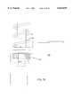
- FIG. 25is a side view of a connection between a second pin and a hub filler according to a second, or preferred, embodiment of the present invention.
- FIG. 1An exemplary first embodiment of a tape drive loading mechanism of the present invention, depicted in FIG. 1, is housed within a transport cabinet 40.
- the transport cabinet 40has a loading door (not depicted) which receives a tape cartridge 10.
- the loading door and a tape cartridge loading and unloading mechanism used to receive and position the tape cartridge 10 within the transport cabinet 40are not depicted in the figures.
- Such a mechanismmay be of conventional design, for example.
- the present invention depicted in FIG. 1is configured to operate with a tape cartridge 10 having a single reel 12 mounted such that the reel 12 may rotate therein.
- the tape 16is wound around the center of the reel 12 and a leader pin 14 is attached to the terminal end of the tape 16, as depicted in FIG. 14.
- the leader pin 14is configured in the shape of a spool with the terminal end of the tape 16 attached to the narrow center portion of the spool.
- the tape cartridge 10includes a recessed portion 18 in which the leader pin 14 rests when the tape 16 is fully wrapped around the reel 12 and therefore in the unloaded state, as in FIG. 1.
- the tape 16runs through an opening slot (not shown) in the recessed portion 18.
- the transport cabinet 40also houses a head assembly 20 capable of reading information from the tape 16 and writing information to the tape 16.
- the head assembly 20is conventional in design. Although the head assembly 20 is depicted in FIGS. 1 and 8, the head assembly 20 is omitted from FIGS. 2-7 and 9-13 for clarity.
- the reel 12, a take-up reel 42, a head 22, and a plurality of tape guides 24are oriented at a common elevation within the transport cabinet 40.
- a motor (not shown) positioned below the take-up reel 42rotates the take-up reel 42 in a counterclockwise direction (Arrow A as viewed in FIG. 1) in order to cause transfer of the tape 16 from reel 12 to reel 42.
- a motor (not shown) positioned below reel 12is capable of engaging reel 12 to rotate reel 12 in a counterclockwise direction (Arrow B as viewed in FIG. 1) in order to transfer the tape 16 from reel 42 to reel 12.
- the tape drive loading mechanismincludes a load member with an elongated first portion or load arm 50 and a second portion or load gear arm 60.
- the tape drive loading mechanismfurther includes a first guide track 47, a second guide track or center track 55, a third guide track 113, a second member or hub filler 100, a motive element such as a linear solenoid 110, a fourth guide track 57, and a motive element such as first drive motor 70.
- the load arm 50has an elongated shape.
- the load arm 50is oriented in a horizontal position and rigidly attached to a vertically oriented first pin or center pin 54 at one end thereof and a vertically oriented second pin 52 at the opposite end thereof.
- the center pin 54extends within the center track 55 and is rotatable and translatable therein.
- the center pin 54is located at a first end 53 of the center track 55.
- the load arm 50is rigidly attached to a vertically oriented radial pin 56 that extends within the fourth guide track 57 and is rotatable and translatable therein.
- the center track 55is linearly shaped and is generally constructed by forming a slot through a planar member 46.
- the fourth guide track 57has a linear portion 58 and an arcuate portion 59 and is also constructed by forming a slot through the planar member 46.
- the linear portion 58 of the fourth guide track 57is parallel to the center track 55.
- the linear portion 58 of the fourth guide track 57is spaced apart from the center track 55 by a distance substantially equal to the distance between the center pin 54 and the radial pin 56.
- the arcuate portion 59 of the fourth guide track 57has a constant radius of curvature substantially equal to the distance between the center pin 54 and the radial pin 56.
- the load gear arm 60has a generally elongated shape and is oriented in a horizontal position.
- the load gear arm 60is rigidly attached to the center pin 54 and to the radial pin 56, and thereby rigidly attached to the load arm 50.
- the load arm 50 and the load gear arm 60lie in different elevations.
- the load gear arm 60has gear teeth 62 extending outward along a linear side portion 63.
- the linear side portion 63extends approximately thirty-six millimeters, but this is exemplary only.
- the gear teeth 62also extend along an arcuate portion 64 over an arc of approximately 180°.
- the arcuate portion 64has a constant radius of curvature.
- the hub filler 100is an elongated member having a profile with one long side 101 that is straight and an opposing long side 103 that is generally arcuately shaped.
- One short side 105 of the hub filler 100is attached to the load arm 50 at the second pin 52, while the opposing short side 107 is slightly arcuately shaped.
- the hub filler 100is rotatable about the second pin 52.
- a slot 104 of the hub filler 100receives the tape leader pin 14 located on long side 103 at approximately 2/3 the length of the hub filler 100 away from the second pin 52.
- the slot 104includes a recessed portion 106 that extends towards short side 107.
- the recessed portion 106is large enough for the leader pin 14 to fit therein.
- the recessed portion 106prevents the leader pin 14 from sliding out of the slot 104 during motion of the hub filler 100.
- the hub filler 100has a vertically oriented guide pin 102 attached thereto located at approximately 1/3 the length of the hub filler 100 away from the second pin 52.
- the guide pin 102has a portion that extends above the hub filler 100 and is capable of extending within the first guide track 47 when the hub filler 100 is positioned below the first guide track 47.
- the guide pin 102has a portion that extends below the hub filler 100 and is capable of extending within the third guide track 113 when the hub filler 100 is positioned over the third guide track 113.
- the first guide track 47has a linear portion 48 (see FIG. 1) and an arcuate portion 49 and is constructed by forming a slot through the planar member 46.
- the planar member 46is arranged in a plane between the hub filler 100 and the load arm 50.
- the linear portion 48 of the first guide track 47is parallel to the center track 55.
- the arcuate portion 49has a radius of curvature equal to the distance between the center pin 54 and the second pin 52.
- the linear portion 48 of the first guide track 47extends to a position adjacent to a radial channel 44 in take-up reel 42 for receiving the hub filler 100 and the tape leader pin 14.
- the automatic tape loading mechanismincludes a third guide track 113 that has a slot 117.
- the third guide track 113has a first end 114 located adjacent a terminal end of the first guide track 47.
- a first end of the third guide track 113is mounted on an upper terminal end of a third pin 116.
- the third guide track 113rotates about the third pin 116.
- the lower portion of the guide pin 102extends below the hub filler 100 and into the third guide track 113 when the hub filler 100 is positioned over the third guide track 113.
- the solenoid 110is mounted to the transport cabinet 40 and includes an extensible member 111 connected to the third guide track 113 near the second end 115 by pin 112.
- the solenoid 110operates in a conventional manner and therefore is not described herein in detail.
- the solenoid 110uses the extensible member 111 to force the third guide track 113 to rotate about the third pin 116.
- the extensible member 111 of the solenoid 110is extended when the guide pin 102 of the hub filler 100 is located near the second end 115 of the third guide track 113, as depicted in FIG. 3.
- the extensible member 111 of the solenoid 110is used to rotate the third guide track 113 about the third pin 116, thereby pushing the guide pin 102 and forcing the hub filler 100 to rotate about the second pin 52. This movement will be shown in later Figures.
- the illustrated exemplary first embodiment of the present inventionincludes a first drive motor 70 driving a plurality of interconnecting gears including a worm 72 having teeth which are engaged to a mating worm gear 74.
- Worm gear 74transfers the motion from worm 72 to gear 76 that is rigidly connected to worm gear 74.
- Gear 76is a spur gear having teeth that are engaged with teeth on spur gear 78, which are engaged to the teeth on spur gear 80.
- Gear 80has teeth that are engaged to the gear teeth 62 on the load gear arm 60.
- the plurality of interconnected gearsallow the first drive motor 70 to force the load gear arm 60 and the load arm 50 to rotate and translate on the center pin 54 within the center track 55.
- the motion of the load gear arm 60 and connected load arm 50can be controlled by the direction and amount of rotation of the worm 72 caused by the motor 70 that includes an encoder.
- FIGS. 1-13depict the tape drive loading mechanism at various positions as it brings the tape cartridge 10 from the unloaded state to the loaded state.
- FIGS. 1 and 2depict the load arm 50 and the load gear arm 60 in the start position, and the tape cartridge 10 in the unloaded state.
- FIGS. 12 and 13depict the load arm 50 and the load gear arm 60 in the end position, and the tape cartridge in the loaded state.
- the load arm 50in the start position the load arm 50 is positioned so the hub filler 100 is located outside but near the tape cartridge 10 and the guide pin 102 is positioned within the arcuate portion 49 of the first guide track 47.
- the hub filler 100should not interfere with the loading and unloading of the tape cartridge 10 from the transport cabinet 40 when the tape drive loading mechanism is in the start position.
- the extensible member 111 of the solenoid 110is in the retracted position when the tape drive loading mechanism is in the start position.
- the tape cartridge 10is in the unloaded state wherein the leader pin 14 rests within the recessed portion 18 and the tape 16 is fully wrapped around the reel 12.
- the motor 70is then activated such that it causes, through the gear assembly's connection with the gear teeth 62, the clockwise rotation of the load gear arm 60 in the direction of arrow C.
- the clockwise rotation of the load gear arm 60 about the center pin 54causes the clockwise rotation of the load arm 50.
- the clockwise rotation of the load arm 50forces the hub filler 100 to move and the guide pin 102 to translate along the first guide track 47 to the third guide track 113.
- the location of the first end 114 of the third guide track 113 directly below the terminal end of the first guide track 47ensures that the guide pin 102 will slide smoothly from the first guide track 47 into the third guide track 113, and vice versa.
- the radial pin 56will hit a terminal end 120 of the fourth guide track 57.
- the contact between the terminal end 120 of the fourth guide track 57 and the radial pin 56will prevent the load arm 50 from rotating to a point at which the guide pin 102 extends beyond the second end 115 of the third guide track 113.
- FIG. 3depicts the hub filler 100 positioned adjacent the leader pin 14. This position represents the furthest clockwise rotation of the load gear arm 60 and the load arm 50.
- the movement of the extensible member 111 of the solenoid 110extends which causes the third guide track 113 to rotate in a clockwise direction about the third pin 116.
- the clockwise rotation of the third guide track 113pushes the guide pin 102, thereby forcing the hub filler 100 to rotate in a clockwise direction about the second pin 52 to a position as depicted in FIG. 4.
- the leader pin 14is positioned within the slot 104 of the hub filler 100.
- the hub filler 100is rotated by the movement of the extensible member 111 of the solenoid 110 from the retracted position, as depicted in FIGS. 1-3, to the extended position, as depicted in FIG. 4.
- the extensible member 111 of the solenoid 110remains in the extended position until the leader pin 14 is unloaded.
- the motor 70is used to slightly rotate the load arm 50 in a counterclockwise direction about the center pin 54 to a position depicted in FIG. 5. In this position the leader pin 14 is positioned within the recessed portion 106 of the hub filler 100 to prevent the leader pin 14 from sliding out of the slot 104 during subsequent motion of the hub filler 100.
- the direction of rotation of the motor 70is reversed thereby causing the plurality of gears to rotate in reverse directions. The plurality of gears act upon the arcuate portion 64 of the gear teeth 62 of the load gear arm 60 to cause the counterclockwise rotation of the load gear arm 60 and the load arm 50.
- the motor 70then continues to rotate the load gear arm 60 and the load arm 50 in a counterclockwise direction about the center pin 54 to a position as depicted in FIG. 6.
- the hub filler 100begins to pull the leader pin 14, and thereby begins to unwind the tape 16 from the reel 12.
- the guide pin 102 of the hub filler 100is being guided by the third guide track 113 towards the first guide track 47.
- the leader pin 14is still within the angular mouth opening or recessed portion 18 in the tape cartridge 10.
- the motor 70continues to rotate the load gear arm 60 and the load arm 50 in a counterclockwise direction about the center pin 54 to a position as depicted in FIG. 7.
- the load arm 50continues to force hub filler 100 to unwind the tape 16 from the reel 12 and the leader pin 14 is pulled free from the tape cartridge 10.
- the guide pin 102 of the hub filler 100is now positioned within the arcuate portion 49 of the first guide track 47.
- the motor 70continues to rotate the load gear arm 60 and the load arm 50 in a counterclockwise direction about the center pin 54 to a position as depicted in FIG. 8.
- the load arm 50continues to force hub filler 100 to unwind the tape 16 from the reel 12.
- the guide pin 102travels within the arcuate portion 49 of the first guide track 47 and the radial pin 56 travels within the arcuate portion 59 of the fourth guide track 57.
- FIG. 8depicts the hub filler 100 as it passes the head 22 of the head assembly 20.
- the tape 16is positioned in contact with the head 22 in order to facilitate the transfer of data between the head assembly 20 and the data storage medium or tape 16.
- the tape 16is guided by a plurality of tape guides 24 that properly position the tape 16 against the head 22 and prevent any damage to the tape 16.
- the tape guides 24are of a conventional type.
- FIG. 9depicts a position at which the load arm 50 switches from rotating counterclockwise about the center pin 54 to translating along the center track 55. This change from rotation to translation is caused by several factors.
- One factoris that the teeth of the spur gear 80 are engaged with the gear teeth 62 of the load gear arm 60 at the junction of the arcuate portion 64 and the linear portion 63.
- a second factoris that in this position the linear portion 63 of the gear teeth 62 are parallel to both the linear portion 58 of the fourth guide track 57 and the linear portion 48 of the first guide track 47.
- a third factoris that the radial pin 56 is positioned at the junction of the arcuate portion 59 and the linear portion 58 of the fourth guide track 57.
- the load gear arm 60is no longer constrained by the radial pin 56 to pure rotation, but rather the load gear arm 60 is free to translate along the center track 55. Additionally, the load arm 50 is fully rotated in a counterclockwise direction with the second pin 52 being positioned at the junction of the arcuate portion 49 and the linear portion 48 of the first guide track 47. A notched portion 43 is cut in the take-up reel 42 to prevent interference between the second pin 52 and the planar member 46 and interference between the guide pin 102 and the planar member 46 at this position.
- the motor 70continues to rotate in the same direction as it rotated to cause a counterclockwise rotation of the load gear arm 60.
- the plurality of gearsare engaged with the gear teeth 62 along the linear portion 63 of the load gear arm 60, thereby causing a linear translation of the load gear arm 60 along the center track 55.
- the radial pin 56is forced to translate within the linear portion 58 of the fourth guide track 57.
- the recessed portion 106 of the slot 104 of the hub filler 100serves an important function to ensure the proper operation of this embodiment of the present invention.
- the recessed portion 106acts as a lip which prevents the leader pin 14 from sliding out of the slot 104.
- the angle of the tape 16 extending from the leader pin 14should not exceed approximately 90° from the long side 101.
- the motor 70continues to rotate in the same direction as it rotated to cause a counterclockwise rotation of the load gear arm 60, thereby causing a linear translation of the load gear arm 60 along the center track 55 to a position as depicted in FIG. 11. In this position the angle of the tape 16 extending from the leader pin 14 should not exceed approximately 90° from the long side 101.
- FIG. 12depicts the load arm 50 and the hub filler 100 in the end position and the tape cartridge 10 in the loaded state.
- the second pin 52is located at the center 45 of the take-up reel 42.
- the hub filler 100is shaped and sized to fit within the channel 44 of the take-up reel 42.
- the radius of curvature of short side 107is equal to the radius of curvature of the hub 41 of the take-up reel 42 so that the short side 107 sits flush with the hub 41.
- the load arm 50will remain stationary in the end position until unloading of the leader pin 14.
- the motor 70stops rotating, and thereby discontinues the travel of the load gear arm 60 and the load arm 50 along the center track 55.
- the center pin 54has reached a position near a second end 51 of the center track 55 and the radial pin 56 has reached an end of the linear portion 58 of the fourth guide track 57.
- the tape leader pin 14is positioned to begin winding the tape 16 about the hub 41 of the take-up reel 42.
- the motor(not shown) positioned below reel 42 is used to rotate the take-up reel 42 in a counterclockwise direction, to a position as depicted in FIG. 13.
- the take-up reel 42rotates the tape 16 is transferred from reel 12 to take-up reel 42 and data is transferred between the tape 16 and the head assembly 20.
- FIG. 13depicts the take-up reel 42 rotating in the counterclockwise direction with the tape 16 being wrapped around the hub 41 of the take-up reel 42.
- the hub filler 100sits within the radial channel 44 and rotates with the take-up reel 42.
- the unloading processinvolves reversing the above procedure.
- a motor(not shown) is positioned below reel 12 which is capable of engaging reel 12 to rotate reel 12 in a counterclockwise direction (as viewed in FIG. 13).
- the motor driving reel 12forces the tape 16 to unwind from the take-up reel 42 and causes the take-up reel 42 and the hub filler 100 to rotate in a clockwise direction.
- the rotation of reel 12is temporarily slowed or stopped and the motor 70 is activated.
- the return trip of the hub filler 100is caused by a reversal of the direction of rotation of the motor 70 as compared to the direction of rotation of the motor 70 during loading of the hub filler 100.
- the motor that drives reel 12prevents slack from forming during the return trip of the hub filler 100 and the leader pin 14 from the take-up reel 42 to the tape cartridge 10.
- a conventional electronic or mechanical methodis used to prevent the motor driving reel 12 from rotating at a speed or with a torque that will cause the leader pin 14 to pull hard against the loading mechanism.
- the tape cartridge 10may be removed from the transport cabinet using the loading and unloading mechanism (not shown).
- the tape drive loading mechanismincludes a load member with an elongated first portion or load arm 250 and a second portion or load gear arm 260.
- the tape drive loading mechanismfurther includes a first guide track 247, a second guide track 255, a third guide track 313, a second member or hub filler 300, a motive element 310, a fourth guide 257, and a motive element 270 (depicted in FIG. 23).
- the load arm 250has an elongated shape.
- the load arm 250is oriented in a horizontal position and is rotatably and translatably attached to a vertically oriented first pin or center pin 254 (depicted in FIG. 21) at one end thereof and a vertically oriented second pin 252 at the opposite end thereof.
- the second pin 252, as depicted in FIG. 25,is attached to the hub filler 300 by a bearing assembly 452 and is stabilized using a spring 454.
- the center pin 254extends within the center track 255, which is rotatable and translatable thereabout.
- the center pin 254is located at a first end 253 of the center track 255.
- the load arm 250is rigidly attached to a vertically oriented member 256 that engages the fourth guide track 257 and is rotatable and translatable thereon.
- the center track 255is linearly shaped and is generally constructed by forming a slot through the load gear arm 260.
- the fourth guide track 257has a linear portion 258 and an arcuate portion 259 and is also constructed by forming a guide mounted to the planar member 246.
- the linear portion 258 of the fourth guide track 257is parallel to the center track 55. When they are in a parallel alignment, the linear portion 258 of the fourth guide track 257 is spaced apart from the center track 255 by a distance substantially equal to the distance between the center pin 254 and the offset member 256 when the center pin 254 is located at the first end 253 of the center track 255.
- the arcuate portion 259 of the fourth guide track 257has a constant radius of curvature substantially equal to the distance between the center pin 254 and the offset member 256 when the center pin 254 is located at the first end 253 of the center track 255.
- the load gear arm 260has a generally elongated shape and is oriented in a horizontal position.
- the load gear arm 260is rigidly attached to the load arm 250.
- the load arm 250 and the load gear arm 260lie in different elevations.
- the load gear arm 260has gear teeth 262 extending outward along a linear side portion 263.
- the linear side portion 263extends approximately thirty-six millimeters, but this is exemplary only.
- the gear teeth 262also extend along an arcuate portion 264 over an arc of approximately 180°.
- the arcuate portion 264has a constant radius of curvature.
- the hub filler 300is an elongated member having a profile with one long side 301 that is straight and an opposing long side 303 that is generally arcuately shaped.
- One short side 305 of the hub filler 300is attached to the load arm 250 at the second pin 252, while the opposing short side 307 is slightly arcuately shaped.
- the hub filler 300is rotatable about the second pin 252.
- a slot 304 of the hub filler 300receives the tape leader pin 214 located on long side 303 at approximately 2/3 the length of the hub filler 300 away from the second pin 252.
- the slot 304includes a recessed portion 306 that extends towards short side 307.
- the recessed portion 106is large enough for the leader pin 214 to fit therein.
- the recessed portion 306prevents the leader pin 214 from sliding out of the slot 304 during motion of the hub filler 300.
- the hub filler 300has a vertically oriented guide pin 302 attached thereto located at approximately 1/3 the length of the hub filler 300 away from the second pin 252.
- the guide pin 302has a portion that extends below the hub filler 300 and is capable of extending within the first guide track 247 when the hub filler 300 is positioned above the first guide track 247.
- the guide pin 302has a portion that extends below the hub filler 300 and is capable of extending within the third guide track 313 when the hub filler 300 is positioned over the third guide track 313.
- the first guide track 247has a linear portion 248 (see FIG. 16) and an arcuate portion 249 and is constructed by forming a slot through the lower planar member 446.
- the lower planar member 446is arranged in a plane below the hub filler 300 and the load arm 250.
- the arcuate portion 249has a radius of curvature equal to the distance between the center pin 254 and the second pin 252 when the center pin 254 is located at the first end 253 of the center track 255.
- the linear portion 248 of the first guide track 247extends to a position adjacent to a radial channel 244 in take-up reel 242 for receiving the hub filler 300 and the tape leader pin 214.
- the automatic tape loading mechanismincludes a third guide track 313 that has a slot 317.
- the third guide track 313has a first end 314 located adjacent a terminal end of the first guide track 247.
- a first end of the third guide track 313is mounted on an upper terminal end of a third pin 316.
- the third guide track 313rotates about the third pin 316.
- the lower portion of the guide pin 302extends below the hub filler 300 and into the third guide track 313 when the hub filler 300 is positioned over the third guide track 313.
- the motive element 310is mounted to the transport cabinet 240 and includes an gear member 311 engaged to a gear portion on the third guide track 313 near the second end 315.
- the motive element 310operates in a conventional manner and therefore is not described herein in detail.
- the motive element 310uses a shaft having a gear thereon to rotate the gear member 311 to force the third guide track 313 to rotate about the third pin 316.
- the gear member 311 of the motive element 310is rotated counterclockwise when the guide pin 302 of the hub filler 300 is located near the second end 315 of the third guide track 313, as depicted in FIG. 18.
- the gear member 311 of the motive element 310is used to rotate the third guide track 313 about the third pin 316, thereby pushing the guide pin 302 and forcing the hub filler 300 to rotate about the second pin 252. This movement will be shown in later Figures.
- the second embodiment of the present inventionincludes a first drive motor 270 (or motive element) driving a plurality of interconnecting gears including a worm 272 having teeth which are engaged to a mating worm gear 274, as depicted in FIG. 23.
- Worm gear 274transfers the motion from worm 272 to gear 276 that is rigidly connected to worm gear 274.
- Gear 276is a spur gear having teeth that are engaged with teeth on spur gear 278, which are engaged to the teeth on spur gear 280.
- Gear 280has teeth that are engaged to the gear teeth 262 on the load gear arm 260.
- the plurality of interconnected gearsallow the first drive motor 270 to force the load gear arm 260 and the load arm 250 to rotate and translate on the center pin 254 within the center track 255.
- the motion of the load gear arm 260 and connected load arm 250can be controlled by the direction and amount of rotation of the worm 272 caused by the motor 270 that includes an encoder.
- FIGS. 15-21depict the tape drive loading mechanism at various positions as it brings the tape cartridge 210 from the unloaded state to the loaded state.
- FIGS. 15 and 16depict the load arm 250 and the load gear arm 260 in the start position, and the tape cartridge 210 in the unloaded state.
- FIG. 21depicts the load arm 250 and the load gear arm 260 in the end position, and the tape cartridge in the loaded state.
- the load arm 250in the start position the load arm 250 is positioned so the hub filler 300 is located outside but near the tape cartridge 210 and the guide pin 302 is positioned within the arcuate portion 249 of the first guide track 247.
- the hub filler 300should not interfere with the loading and unloading of the tape cartridge 210 from the transport cabinet 240 when the tape drive loading mechanism is in the start position.
- the gear member 311 of the motive element 310is in the start position when the tape drive loading mechanism is in the start position.
- the tape cartridge 210is in the unloaded state wherein the leader pin 214 rests within the recessed portion 218 and the tape 216 is fully wrapped around the reel 212.
- the motor 270is then activated such that it causes, through the gear assembly's connection with the gear teeth 262, the clockwise rotation of the load gear arm 260 in the direction of arrow D.
- the clockwise rotation of the load gear arm 260 about the center pin 254causes the clockwise rotation of the load arm 250.
- the clockwise rotation of the load arm 250forces the hub filler 300 to move and the guide pin 302 to translate along the first guide track 247 to the third guide track 313.
- the location of the first end 314 of the third guide track 313 directly adjacent the terminal end of the first guide track 247ensures that the guide pin 302 will slide smoothly from the first guide track 247 into the third guide track 313, and vice versa.
- FIG. 18depicts the hub filler 300 positioned adjacent the leader pin 214. This position represents the furthest clockwise rotation of the load gear arm 260 and the load arm 250.
- the movement of the gear member 311 of the motive element 310rotates counterclockwise which causes the third guide track 313 to rotate in a clockwise direction about the third pin 316.
- the clockwise rotation of the third guide track 313pushes the guide pin 302, thereby forcing the hub filler 300 to rotate in a clockwise direction about the second pin 252 to a position as depicted in FIG. 19.
- the leader pin 214is positioned within the slot 304 of the hub filler 300.
- the hub filler 300is rotated by the rotation of the gear member 311 from the start position, as depicted in FIGS. 15-18, to the end position, as depicted in FIG. 19.
- the gear member 311remains in the end position until the leader pin 214 is unloaded.
- the motor 270is used to slightly rotate the load arm 250 in a counterclockwise direction about the center pin 254 to a position depicted in FIG. 20. In this position the leader pin 214 is positioned within the recessed portion 306 of the hub filler 300 to prevent the leader pin 214 from sliding out of the slot 304 during subsequent motion of the hub filler 300.
- the direction of rotation of the motor 270is reversed thereby causing the plurality of gears to rotate in reverse directions.
- the plurality of gearsact upon the arcuate portion 264 of the gear teeth 262 of the load gear arm 260 to cause the counterclockwise rotation of the load gear arm 260 and the load arm 250.
- the motor 270then continues to rotate the load gear arm 260 and the load arm 250 in a counterclockwise direction about the center pin 254.
- the hub filler 300begins to pull the leader pin 214, and thereby begins to unwind the tape 216 from the reel 212.
- the guide pin 302 of the hub filler 300is being guided by the third guide track 313 towards the first guide track 247.
- the load arm 250continues to force hub filler 300 to unwind the tape 216 from the reel 212 and the leader pin 214 is pulled free from the tape cartridge 210.
- the guide pin 302 of the hub filler 300moves within the arcuate portion 249 of the first guide track 247.
- the guide pin 302travels within the arcuate portion 249 of the first guide track 247 and the offset member 256 travels along the arcuate portion 259 of the fourth guide track 257.
- the hub filler 300travels past the head 222 of the head assembly 220 as described for the first embodiment. As the hub filler 300 passes the head assembly 220, there is clearance between the hub filler 300 and the head 222 and between the hub filler 300 and the side of the transport cabinet 240.
- the tape 216is positioned in contact with the head 222 in order to facilitate the transfer of data between the head assembly 220 and the data storage medium or tape 216. As the hub filler 300 pulls the tape 216, the tape 216 is guided by a plurality of tape guides 224 that properly position the tape 216 against the head 222 and prevent any damage to the tape 216.
- the load arm 250continues to rotate and translate in a similar manner as described above for the first embodiment until the load arm 250 reaches the position depicted in FIG. 21.
- FIG. 21depicts the load arm 250 and the hub filler 300 in the end position and the tape cartridge 210 in the loaded state.
- the second pin 252is located at the center 245 of the take-up reel 242.
- the hub filler 300is shaped and sized to fit within the channel 244 of the take-up reel 242.
- the load arm 250will remain stationary in the end position until unloading of the leader pin 214.
- the motor 270stops rotating, and thereby discontinues the travel of the load gear arm 260 and the load arm 250 along the center track 255.
- the center pin 254has reached a position near a second end 251 of the center track 255 and the offset member 256 has reached an end of the linear portion 258 of the fourth guide track 257.
- the tape leader pin 214is positioned to begin winding the tape 216 about the hub 241 of the take-up reel 242.
- Sensorsmay be used on either of the embodiments to control the motion of the first and second motive elements and the motors used to control the rotation of the reels.
- a magnet 500is positioned on the load arm 250 and hall effect sensors 502 are positioned at various points on the cabinet or the planar members such that as the load arm 250 rotates and translates the magnet 500 will pass near the sensors 502.
- opto-interrupt or reflect sensors 504may be used to detect the position of the hub filler 300.
- a mechanical switch 506may be used to detect the positioning of the third guide track 313.
- the various parts of the tape drive loading mechanism of the present inventionare constructed of conventional materials that are rigid, lightweight, and durable. Examples of such materials include, but are not limited to, plastics, lightweight metals, or composite materials.
- the amount of friction between various moving partsshould be minimized through the use of conventional lubricants and the manufacture of the various parts using low friction materials.
Landscapes
- Winding Of Webs (AREA)
Abstract
Description
Claims (19)
Priority Applications (1)
| Application Number | Priority Date | Filing Date | Title |
|---|---|---|---|
| US09/100,750US6034839A (en) | 1997-11-07 | 1998-06-22 | Mechanism and method for loading a tape from a cartridge to a take-up reel |
Applications Claiming Priority (2)
| Application Number | Priority Date | Filing Date | Title |
|---|---|---|---|
| US6481497P | 1997-11-07 | 1997-11-07 | |
| US09/100,750US6034839A (en) | 1997-11-07 | 1998-06-22 | Mechanism and method for loading a tape from a cartridge to a take-up reel |
Publications (1)
| Publication Number | Publication Date |
|---|---|
| US6034839Atrue US6034839A (en) | 2000-03-07 |
Family
ID=26744921
Family Applications (1)
| Application Number | Title | Priority Date | Filing Date |
|---|---|---|---|
| US09/100,750Expired - LifetimeUS6034839A (en) | 1997-11-07 | 1998-06-22 | Mechanism and method for loading a tape from a cartridge to a take-up reel |
Country Status (1)
| Country | Link |
|---|---|
| US (1) | US6034839A (en) |
Cited By (51)
| Publication number | Priority date | Publication date | Assignee | Title |
|---|---|---|---|---|
| EP1098307A3 (en)* | 1999-11-05 | 2001-07-18 | Nec Corporation | Threading mechanism for magnetic recording/reproducing apparatus |
| US6278572B1 (en)* | 1998-11-12 | 2001-08-21 | U.S. Philips Corporation | Recording and/or reproducing device having drive means for the actuation of holder means for a cassette and of retaining means for a tape pull-out element |
| US6349016B1 (en)* | 1997-12-22 | 2002-02-19 | Fuji Photo Film Co., Ltd. | Magnetic tape cartridge |
| US6378796B1 (en) | 1999-10-08 | 2002-04-30 | Seagate Technology Llc | Apparatus and method for de-coupling grabber from take-up reel |
| US6437938B1 (en)* | 1999-05-18 | 2002-08-20 | Nec Corporation | Loading/threading mechanism of cartridge magnetic tape apparatus |
| US20030075633A1 (en)* | 2001-10-18 | 2003-04-24 | Nec Corporation | Magnetic tape drive apparatus |
| US20030080228A1 (en)* | 2001-10-15 | 2003-05-01 | Fuji Photo Film Co., Ltd. | Recording tape cartridge |
| US20030094530A1 (en)* | 2001-11-20 | 2003-05-22 | Fuji Photo Film Co., Ltd. | Recording tape cartridge |
| US6612512B1 (en)* | 1999-11-11 | 2003-09-02 | Koninklijke Philips Electronics N.V. | Recording and/or reproducing device having a pull-out element and having means for moving the pull-out element into its nominal position |
| US6619577B2 (en) | 2000-04-27 | 2003-09-16 | Seagate Removable Storage Solutions Llc | Position sensors for tape loading mechanism |
| US6626387B1 (en)* | 2000-07-25 | 2003-09-30 | Seagate Removable Storage Solutions Llc | Rolling element for guiding a hub filler in a tape drive |
| WO2003083865A1 (en)* | 2002-04-02 | 2003-10-09 | International Business Machines Corporation | Sensing position of pin on tape inside cartridge shell |
| US6637691B1 (en) | 2000-05-25 | 2003-10-28 | Seagate Removable Storage Solutions, Llc | Latching mechanism for tape drive |
| US20040004143A1 (en)* | 2002-07-03 | 2004-01-08 | Gavit Stephan E. | Tape threading apparatus having take-up hub with gap filling block for data storage systems and method therefor |
| US6739539B2 (en) | 2001-10-15 | 2004-05-25 | Fuji Photo Film Co., Ltd. | Recording tape cartridge |
| US6742738B2 (en) | 2001-11-20 | 2004-06-01 | Fuji Photo Film Co., Ltd. | Recording tape cartridge |
| US6744593B1 (en)* | 2000-03-03 | 2004-06-01 | Seagate Technology Llc. | Tape path for a cartridge tape drive |
| US20040129816A1 (en)* | 2002-12-19 | 2004-07-08 | Hamming John A. | Tape drive apparatus having an arrangement for capturing and retaining a leader pin from a tape cartridge |
| US20040169101A1 (en)* | 2003-02-27 | 2004-09-02 | Havard Hoelsaeter | System for extracting magnetic recording tape from a tape cartridge for engagement with a take-up reel |
| US6804077B1 (en) | 2000-07-25 | 2004-10-12 | Certance Llc | Method and apparatus for reinitializing a tape drive after a power loss |
| US6827307B2 (en) | 2001-10-15 | 2004-12-07 | Fuji Photo Film Co., Ltd. | Recording tape cartridge |
| US6840473B2 (en) | 2001-11-20 | 2005-01-11 | Fuji Photo Film Co., Ltd. | Recording tape cartridge |
| US6845935B2 (en) | 2001-11-20 | 2005-01-25 | Fuji Photo Film Co., Ltd. | Recording tape cartridge |
| US6854678B2 (en) | 2001-11-20 | 2005-02-15 | Fuji Photo Film Co., Ltd. | Recording tape cartridge and drive device |
| US20050035237A1 (en)* | 2003-08-15 | 2005-02-17 | International Business Machines Corporation | Apparatus and method to releaseably attach a tape leader pin |
| US20050237184A1 (en)* | 2000-01-24 | 2005-10-27 | Scott Muirhead | RF-enabled pallet |
| US20050258292A1 (en)* | 2001-10-15 | 2005-11-24 | Fuji Photo Film Co., Ltd. | Recording tape cartridge |
| US6988686B2 (en) | 2001-11-20 | 2006-01-24 | Fuji Photo Film Co., Ltd. | Recording tape cartridge |
| US7004418B2 (en) | 2001-10-15 | 2006-02-28 | Fuji Photo Film Co., Ltd. | Recording tape cartridge |
| US20060161578A1 (en)* | 2005-01-19 | 2006-07-20 | Siegel Hilliard B | Method and system for providing annotations of a digital work |
| US20060209447A1 (en)* | 2005-03-17 | 2006-09-21 | Hamming John A | System and method for protecting head elements of a tape drive |
| US20080122610A1 (en)* | 2000-01-24 | 2008-05-29 | Nextreme L.L.C. | RF-enabled pallet |
| US20080168073A1 (en)* | 2005-01-19 | 2008-07-10 | Siegel Hilliard B | Providing Annotations of a Digital Work |
| US20080195962A1 (en)* | 2007-02-12 | 2008-08-14 | Lin Daniel J | Method and System for Remotely Controlling The Display of Photos in a Digital Picture Frame |
| US20080243788A1 (en)* | 2007-03-29 | 2008-10-02 | Reztlaff James R | Search of Multiple Content Sources on a User Device |
| US7455254B1 (en) | 2000-07-25 | 2008-11-25 | Certance Llc | Method and apparatus of maintaining tension in a tape |
| US20080294674A1 (en)* | 2007-05-21 | 2008-11-27 | Reztlaff Ii James R | Managing Status of Search Index Generation |
| US20100188327A1 (en)* | 2009-01-27 | 2010-07-29 | Marcos Frid | Electronic device with haptic feedback |
| US8352449B1 (en) | 2006-03-29 | 2013-01-08 | Amazon Technologies, Inc. | Reader device content indexing |
| US8417772B2 (en) | 2007-02-12 | 2013-04-09 | Amazon Technologies, Inc. | Method and system for transferring content from the web to mobile devices |
| US8423889B1 (en) | 2008-06-05 | 2013-04-16 | Amazon Technologies, Inc. | Device specific presentation control for electronic book reader devices |
| US8571535B1 (en) | 2007-02-12 | 2013-10-29 | Amazon Technologies, Inc. | Method and system for a hosted mobile management service architecture |
| US8725565B1 (en) | 2006-09-29 | 2014-05-13 | Amazon Technologies, Inc. | Expedited acquisition of a digital item following a sample presentation of the item |
| US8793575B1 (en) | 2007-03-29 | 2014-07-29 | Amazon Technologies, Inc. | Progress indication for a digital work |
| US8832584B1 (en) | 2009-03-31 | 2014-09-09 | Amazon Technologies, Inc. | Questions on highlighted passages |
| US8954444B1 (en) | 2007-03-29 | 2015-02-10 | Amazon Technologies, Inc. | Search and indexing on a user device |
| US9087032B1 (en) | 2009-01-26 | 2015-07-21 | Amazon Technologies, Inc. | Aggregation of highlights |
| US9116657B1 (en) | 2006-12-29 | 2015-08-25 | Amazon Technologies, Inc. | Invariant referencing in digital works |
| US9158741B1 (en) | 2011-10-28 | 2015-10-13 | Amazon Technologies, Inc. | Indicators for navigating digital works |
| US9564089B2 (en) | 2009-09-28 | 2017-02-07 | Amazon Technologies, Inc. | Last screen rendering for electronic book reader |
| US9672533B1 (en) | 2006-09-29 | 2017-06-06 | Amazon Technologies, Inc. | Acquisition of an item based on a catalog presentation of items |
Citations (2)
| Publication number | Priority date | Publication date | Assignee | Title |
|---|---|---|---|---|
| US4335858A (en)* | 1980-06-30 | 1982-06-22 | International Business Machines Corporation | Apparatus for threading tape over a tape path including a channel conforming to said path |
| US4608614A (en)* | 1983-06-24 | 1986-08-26 | International Business Machines Corp. | Apparatus for threading magnetic tape in a magnetic tape transport |
- 1998
- 1998-06-22USUS09/100,750patent/US6034839A/ennot_activeExpired - Lifetime
Patent Citations (2)
| Publication number | Priority date | Publication date | Assignee | Title |
|---|---|---|---|---|
| US4335858A (en)* | 1980-06-30 | 1982-06-22 | International Business Machines Corporation | Apparatus for threading tape over a tape path including a channel conforming to said path |
| US4608614A (en)* | 1983-06-24 | 1986-08-26 | International Business Machines Corp. | Apparatus for threading magnetic tape in a magnetic tape transport |
Cited By (93)
| Publication number | Priority date | Publication date | Assignee | Title |
|---|---|---|---|---|
| US6938848B2 (en) | 1997-12-22 | 2005-09-06 | Fuji Photo Film Co., Ltd. | Magnetic tape cartridge |
| US6349016B1 (en)* | 1997-12-22 | 2002-02-19 | Fuji Photo Film Co., Ltd. | Magnetic tape cartridge |
| US6745967B2 (en) | 1997-12-22 | 2004-06-08 | Fuji Photo Film Co., Ltd. | Magnetic tape cartridge |
| US20040206842A1 (en)* | 1997-12-22 | 2004-10-21 | Fuji Photo Film Co., Ltd. | Magnetic tape cartridge |
| US6462906B2 (en) | 1997-12-22 | 2002-10-08 | Kiyoo Morita | Magnetic tape cartridge |
| US20040206841A1 (en)* | 1997-12-22 | 2004-10-21 | Fuji Photo Film Co., Ltd. | Magnetic tape cartridge |
| US6629656B2 (en) | 1997-12-22 | 2003-10-07 | Fuji Photo Film Co., Ltd. | Magnetic tape cartridge |
| US6953170B2 (en) | 1997-12-22 | 2005-10-11 | Fuji Photo Film Co., Ltd. | Magnetic tape cartridge |
| US6278572B1 (en)* | 1998-11-12 | 2001-08-21 | U.S. Philips Corporation | Recording and/or reproducing device having drive means for the actuation of holder means for a cassette and of retaining means for a tape pull-out element |
| US6437938B1 (en)* | 1999-05-18 | 2002-08-20 | Nec Corporation | Loading/threading mechanism of cartridge magnetic tape apparatus |
| US6378796B1 (en) | 1999-10-08 | 2002-04-30 | Seagate Technology Llc | Apparatus and method for de-coupling grabber from take-up reel |
| EP1098307A3 (en)* | 1999-11-05 | 2001-07-18 | Nec Corporation | Threading mechanism for magnetic recording/reproducing apparatus |
| US6471150B1 (en)* | 1999-11-05 | 2002-10-29 | Nec Corporation | Threading mechanism for magnetic recording/reproducing apparatus |
| US6612512B1 (en)* | 1999-11-11 | 2003-09-02 | Koninklijke Philips Electronics N.V. | Recording and/or reproducing device having a pull-out element and having means for moving the pull-out element into its nominal position |
| US20070171080A1 (en)* | 2000-01-24 | 2007-07-26 | Scott Muirhead | Material handling apparatus with a cellular communications device |
| US20050237184A1 (en)* | 2000-01-24 | 2005-10-27 | Scott Muirhead | RF-enabled pallet |
| US20080122610A1 (en)* | 2000-01-24 | 2008-05-29 | Nextreme L.L.C. | RF-enabled pallet |
| US6744593B1 (en)* | 2000-03-03 | 2004-06-01 | Seagate Technology Llc. | Tape path for a cartridge tape drive |
| US6619577B2 (en) | 2000-04-27 | 2003-09-16 | Seagate Removable Storage Solutions Llc | Position sensors for tape loading mechanism |
| US6637691B1 (en) | 2000-05-25 | 2003-10-28 | Seagate Removable Storage Solutions, Llc | Latching mechanism for tape drive |
| US6626387B1 (en)* | 2000-07-25 | 2003-09-30 | Seagate Removable Storage Solutions Llc | Rolling element for guiding a hub filler in a tape drive |
| US20050141121A1 (en)* | 2000-07-25 | 2005-06-30 | Bauer Russell A. | Method and apparatus for reinitializing a tape drive after a power loss |
| US7455254B1 (en) | 2000-07-25 | 2008-11-25 | Certance Llc | Method and apparatus of maintaining tension in a tape |
| US7035033B2 (en) | 2000-07-25 | 2006-04-25 | Certance Llc | Method and apparatus for reinitializing a tape drive after a power loss |
| US6804077B1 (en) | 2000-07-25 | 2004-10-12 | Certance Llc | Method and apparatus for reinitializing a tape drive after a power loss |
| US7051968B2 (en) | 2001-10-15 | 2006-05-30 | Fuji Photo Film Co., Ltd. | Recording tape cartridge |
| US6739539B2 (en) | 2001-10-15 | 2004-05-25 | Fuji Photo Film Co., Ltd. | Recording tape cartridge |
| US20050258292A1 (en)* | 2001-10-15 | 2005-11-24 | Fuji Photo Film Co., Ltd. | Recording tape cartridge |
| US6827307B2 (en) | 2001-10-15 | 2004-12-07 | Fuji Photo Film Co., Ltd. | Recording tape cartridge |
| US20030080228A1 (en)* | 2001-10-15 | 2003-05-01 | Fuji Photo Film Co., Ltd. | Recording tape cartridge |
| US7004418B2 (en) | 2001-10-15 | 2006-02-28 | Fuji Photo Film Co., Ltd. | Recording tape cartridge |
| US7021579B2 (en) | 2001-10-15 | 2006-04-04 | Fuji Photo Film Co., Ltd. | Recording tape cartridge |
| US7204447B2 (en) | 2001-10-15 | 2007-04-17 | Fujifilm Corporation | Recording tape cartridge |
| US20030075633A1 (en)* | 2001-10-18 | 2003-04-24 | Nec Corporation | Magnetic tape drive apparatus |
| US6945488B2 (en)* | 2001-10-18 | 2005-09-20 | Nec Corporation | Magnetic tape drive apparatus |
| US6742738B2 (en) | 2001-11-20 | 2004-06-01 | Fuji Photo Film Co., Ltd. | Recording tape cartridge |
| US20030094530A1 (en)* | 2001-11-20 | 2003-05-22 | Fuji Photo Film Co., Ltd. | Recording tape cartridge |
| US6854678B2 (en) | 2001-11-20 | 2005-02-15 | Fuji Photo Film Co., Ltd. | Recording tape cartridge and drive device |
| US6845935B2 (en) | 2001-11-20 | 2005-01-25 | Fuji Photo Film Co., Ltd. | Recording tape cartridge |
| US6840473B2 (en) | 2001-11-20 | 2005-01-11 | Fuji Photo Film Co., Ltd. | Recording tape cartridge |
| US6974101B2 (en) | 2001-11-20 | 2005-12-13 | Fuji Photo Film Co., Ltd. | Recording tape cartridge |
| US6988686B2 (en) | 2001-11-20 | 2006-01-24 | Fuji Photo Film Co., Ltd. | Recording tape cartridge |
| WO2003083865A1 (en)* | 2002-04-02 | 2003-10-09 | International Business Machines Corporation | Sensing position of pin on tape inside cartridge shell |
| US6889927B2 (en)* | 2002-07-03 | 2005-05-10 | Segway Systems, Llc | Tape threading apparatus having take-up hub with gap filling block for data storage systems and method therefor |
| US20040004143A1 (en)* | 2002-07-03 | 2004-01-08 | Gavit Stephan E. | Tape threading apparatus having take-up hub with gap filling block for data storage systems and method therefor |
| US7066420B2 (en) | 2002-12-19 | 2006-06-27 | Certance Llc | Tape drive apparatus having an arrangement for capturing and retaining a leader pin from a tape cartridge |
| US20040129816A1 (en)* | 2002-12-19 | 2004-07-08 | Hamming John A. | Tape drive apparatus having an arrangement for capturing and retaining a leader pin from a tape cartridge |
| US20040169101A1 (en)* | 2003-02-27 | 2004-09-02 | Havard Hoelsaeter | System for extracting magnetic recording tape from a tape cartridge for engagement with a take-up reel |
| US6908055B2 (en)* | 2003-02-27 | 2005-06-21 | Tandberg Data Asa | System for extracting magnetic recording tape from a tape cartridge for engagement with a take-up reel |
| US6921038B2 (en)* | 2003-08-15 | 2005-07-26 | International Business Machines Corporation | Apparatus and method to releaseably attach a tape leader pin |
| US20050035237A1 (en)* | 2003-08-15 | 2005-02-17 | International Business Machines Corporation | Apparatus and method to releaseably attach a tape leader pin |
| US10853560B2 (en) | 2005-01-19 | 2020-12-01 | Amazon Technologies, Inc. | Providing annotations of a digital work |
| US20080168073A1 (en)* | 2005-01-19 | 2008-07-10 | Siegel Hilliard B | Providing Annotations of a Digital Work |
| US20060161578A1 (en)* | 2005-01-19 | 2006-07-20 | Siegel Hilliard B | Method and system for providing annotations of a digital work |
| US20110184828A1 (en)* | 2005-01-19 | 2011-07-28 | Amazon Technologies, Inc. | Method and system for providing annotations of a digital work |
| US9275052B2 (en) | 2005-01-19 | 2016-03-01 | Amazon Technologies, Inc. | Providing annotations of a digital work |
| US20060209447A1 (en)* | 2005-03-17 | 2006-09-21 | Hamming John A | System and method for protecting head elements of a tape drive |
| US7274528B2 (en) | 2005-03-17 | 2007-09-25 | Certance Llc | System and method for protecting head elements of a tape drive |
| US8352449B1 (en) | 2006-03-29 | 2013-01-08 | Amazon Technologies, Inc. | Reader device content indexing |
| US9292873B1 (en) | 2006-09-29 | 2016-03-22 | Amazon Technologies, Inc. | Expedited acquisition of a digital item following a sample presentation of the item |
| US8725565B1 (en) | 2006-09-29 | 2014-05-13 | Amazon Technologies, Inc. | Expedited acquisition of a digital item following a sample presentation of the item |
| US9672533B1 (en) | 2006-09-29 | 2017-06-06 | Amazon Technologies, Inc. | Acquisition of an item based on a catalog presentation of items |
| US9116657B1 (en) | 2006-12-29 | 2015-08-25 | Amazon Technologies, Inc. | Invariant referencing in digital works |
| US9313296B1 (en) | 2007-02-12 | 2016-04-12 | Amazon Technologies, Inc. | Method and system for a hosted mobile management service architecture |
| US9219797B2 (en) | 2007-02-12 | 2015-12-22 | Amazon Technologies, Inc. | Method and system for a hosted mobile management service architecture |
| US8417772B2 (en) | 2007-02-12 | 2013-04-09 | Amazon Technologies, Inc. | Method and system for transferring content from the web to mobile devices |
| US20080195962A1 (en)* | 2007-02-12 | 2008-08-14 | Lin Daniel J | Method and System for Remotely Controlling The Display of Photos in a Digital Picture Frame |
| US8571535B1 (en) | 2007-02-12 | 2013-10-29 | Amazon Technologies, Inc. | Method and system for a hosted mobile management service architecture |
| US9665529B1 (en) | 2007-03-29 | 2017-05-30 | Amazon Technologies, Inc. | Relative progress and event indicators |
| US20080243788A1 (en)* | 2007-03-29 | 2008-10-02 | Reztlaff James R | Search of Multiple Content Sources on a User Device |
| US8954444B1 (en) | 2007-03-29 | 2015-02-10 | Amazon Technologies, Inc. | Search and indexing on a user device |
| US8793575B1 (en) | 2007-03-29 | 2014-07-29 | Amazon Technologies, Inc. | Progress indication for a digital work |
| US20080294674A1 (en)* | 2007-05-21 | 2008-11-27 | Reztlaff Ii James R | Managing Status of Search Index Generation |
| US9568984B1 (en) | 2007-05-21 | 2017-02-14 | Amazon Technologies, Inc. | Administrative tasks in a media consumption system |
| US9888005B1 (en) | 2007-05-21 | 2018-02-06 | Amazon Technologies, Inc. | Delivery of items for consumption by a user device |
| US8656040B1 (en) | 2007-05-21 | 2014-02-18 | Amazon Technologies, Inc. | Providing user-supplied items to a user device |
| US8965807B1 (en) | 2007-05-21 | 2015-02-24 | Amazon Technologies, Inc. | Selecting and providing items in a media consumption system |
| US8990215B1 (en) | 2007-05-21 | 2015-03-24 | Amazon Technologies, Inc. | Obtaining and verifying search indices |
| US7921309B1 (en) | 2007-05-21 | 2011-04-05 | Amazon Technologies | Systems and methods for determining and managing the power remaining in a handheld electronic device |
| US8234282B2 (en) | 2007-05-21 | 2012-07-31 | Amazon Technologies, Inc. | Managing status of search index generation |
| US8700005B1 (en) | 2007-05-21 | 2014-04-15 | Amazon Technologies, Inc. | Notification of a user device to perform an action |
| US9178744B1 (en) | 2007-05-21 | 2015-11-03 | Amazon Technologies, Inc. | Delivery of items for consumption by a user device |
| US9479591B1 (en) | 2007-05-21 | 2016-10-25 | Amazon Technologies, Inc. | Providing user-supplied items to a user device |
| US8341210B1 (en) | 2007-05-21 | 2012-12-25 | Amazon Technologies, Inc. | Delivery of items for consumption by a user device |
| US8341513B1 (en) | 2007-05-21 | 2012-12-25 | Amazon.Com Inc. | Incremental updates of items |
| US8266173B1 (en) | 2007-05-21 | 2012-09-11 | Amazon Technologies, Inc. | Search results generation and sorting |
| US8423889B1 (en) | 2008-06-05 | 2013-04-16 | Amazon Technologies, Inc. | Device specific presentation control for electronic book reader devices |
| US9087032B1 (en) | 2009-01-26 | 2015-07-21 | Amazon Technologies, Inc. | Aggregation of highlights |
| US8378979B2 (en) | 2009-01-27 | 2013-02-19 | Amazon Technologies, Inc. | Electronic device with haptic feedback |
| US20100188327A1 (en)* | 2009-01-27 | 2010-07-29 | Marcos Frid | Electronic device with haptic feedback |
| US8832584B1 (en) | 2009-03-31 | 2014-09-09 | Amazon Technologies, Inc. | Questions on highlighted passages |
| US9564089B2 (en) | 2009-09-28 | 2017-02-07 | Amazon Technologies, Inc. | Last screen rendering for electronic book reader |
| US9158741B1 (en) | 2011-10-28 | 2015-10-13 | Amazon Technologies, Inc. | Indicators for navigating digital works |
Similar Documents
| Publication | Publication Date | Title |
|---|---|---|
| US6034839A (en) | Mechanism and method for loading a tape from a cartridge to a take-up reel | |
| US4796115A (en) | Tape loading device for a cassette type tape recording and/or reproducing apparatus | |
| US4795109A (en) | Tape cassette loading device | |
| US6515823B2 (en) | Technique for opening door of a tape cartridge to access the tape leader pin | |
| CA1159147A (en) | Magnetic tape recording and/or reproducing apparatus | |
| US4479618A (en) | Tape cassette adapter | |
| KR930011697B1 (en) | Disk Drive Combined Tape Cartridge | |
| EP0628961A2 (en) | A tape tensioning mechanism | |
| US6560062B1 (en) | Recording and/or reproducing device having compact drive means for actuating means for the actuation of holder means for a cassette | |
| KR100225749B1 (en) | Narrow profile data storage cartridge drive of small overall size | |
| US20030209623A1 (en) | Single reel tape cartridge sliding door with auxiliary leader retractor | |
| KR100469225B1 (en) | Recording and / or playback device | |
| US6122136A (en) | Recording and/or reproducing apparatus having a tape loading mechanism | |
| EP0782136A1 (en) | Magnetic tape apparatus for controlling a back tension of a magnetic tape running on a rotary drum | |
| EP0944066B1 (en) | Magnetic recording/reproduction apparatus | |
| US6710979B2 (en) | Method and system for head retraction in a data storage device | |
| US6762904B2 (en) | Magnetic recording and reproduction apparatus | |
| US7334750B2 (en) | Tape drive with leader connecting mechanism | |
| JP3008551B2 (en) | Cam mechanism | |
| US6765750B2 (en) | Tape loading device | |
| EP1408495A2 (en) | Reel brake assembly | |
| JPS6371966A (en) | Cassette tape type magnetic recording and reproducing device | |
| JPS6310360A (en) | Tape driver | |
| JP2007226895A (en) | Recording and reproducing apparatus and take-up reel used for it | |
| JPS62200568A (en) | Magnetic tape drawing mechanism |
Legal Events
| Date | Code | Title | Description |
|---|---|---|---|
| AS | Assignment | Owner name:SEAGATE TECHNOLOGY, INC., CALIFORNIA Free format text:ASSIGNMENT OF ASSIGNORS INTEREST;ASSIGNOR:HAMMING, JOHN A.;REEL/FRAME:009284/0116 Effective date:19980605 | |
| STCF | Information on status: patent grant | Free format text:PATENTED CASE | |
| AS | Assignment | Owner name:SEAGATE REMOVABLE STORAGE SOLUTIONS LLC, CALIFORNI Free format text:ASSIGNMENT OF ASSIGNORS INTEREST;ASSIGNOR:SEAGATE TECHNOLOGY, INC.;REEL/FRAME:010960/0753 Effective date:20000630 | |
| AS | Assignment | Owner name:CHASE MANHATTAN BANK, AS COLLATERAL AGENT, THE, NE Free format text:SECURITY AGREEMENT;ASSIGNOR:SEAGATE REMOVABLE STORAGE SOLUTIONS LLC;REEL/FRAME:011436/0001 Effective date:20001122 | |
| FPAY | Fee payment | Year of fee payment:4 | |
| AS | Assignment | Owner name:CERTANCE LLC (FORMERLY SEAGATE REMOVABLE STORAGE S Free format text:RELEASE;ASSIGNOR:JPMORGAN CHASE BANK;REEL/FRAME:015918/0321 Effective date:20041101 | |
| AS | Assignment | Owner name:CERTANCE LLC, CALIFORNIA Free format text:ASSIGNMENT OF ASSIGNORS INTEREST;ASSIGNOR:SEAGATE REMOVABLE STORAGE SOLUTIONS, LLC;REEL/FRAME:018260/0302 Effective date:20030401 | |
| AS | Assignment | Owner name:KEYBANK NATIONAL ASSOCIATION, AS ADMINISTRATIVE AG Free format text:INTELLECTUAL PROPERTY SECURITY AGREEMENT (SECOND LIEN);ASSIGNOR:QUANTUM CORPORATION;REEL/FRAME:018268/0475 Effective date:20060822 | |
| AS | Assignment | Owner name:KEYBANK NATIONAL ASSOCIATION, AS ADMINISTRATIVE AG Free format text:INTELLECTUAL PROPERTY SECURITY AGREEMENT (FIRST LIEN);ASSIGNOR:QUANTUM CORPORATION;REEL/FRAME:018303/0336 Effective date:20060822 | |
| AS | Assignment | Owner name:CERTANCE LLC, CALIFORNIA Free format text:CHANGE OF NAME;ASSIGNOR:SEAGATE REMOVABLE STORAGE SOLUTIONS LLC;REEL/FRAME:019529/0409 Effective date:20030407 | |
| AS | Assignment | Owner name:QUANTUM CORPORATION, CALIFORNIA Free format text:TERMINATION OF SECURITY INTEREST IN PATENTS REEL 018269 FRAME 0005 AND REEL 018268 FRAME 0475;ASSIGNOR:KEY BANK, NATIONAL ASSOCIATION;REEL/FRAME:019550/0659 Effective date:20070712 Owner name:QUANTUM CORPORATION,CALIFORNIA Free format text:TERMINATION OF SECURITY INTEREST IN PATENTS REEL 018269 FRAME 0005 AND REEL 018268 FRAME 0475;ASSIGNOR:KEY BANK, NATIONAL ASSOCIATION;REEL/FRAME:019550/0659 Effective date:20070712 | |
| AS | Assignment | Owner name:QUANTUM CORPORATION, CALIFORNIA Free format text:RELEASE OF INTELLECTUAL PROPERTY SECURITY AGREEMENT AT REEL 018303 FRAME 0336;ASSIGNOR:KEYBANK NATIONAL ASSOCIATION;REEL/FRAME:019562/0958 Effective date:20070712 | |
| AS | Assignment | Owner name:CREDIT SUISSE, NEW YORK Free format text:SECURITY AGREEMENT;ASSIGNORS:QUANTUM CORPORATION;ADVANCED DIGITAL INFORMATION CORPORATION;CERTANCE HOLDINGS CORPORATION;AND OTHERS;REEL/FRAME:019605/0159 Effective date:20070712 Owner name:CREDIT SUISSE,NEW YORK Free format text:SECURITY AGREEMENT;ASSIGNORS:QUANTUM CORPORATION;ADVANCED DIGITAL INFORMATION CORPORATION;CERTANCE HOLDINGS CORPORATION;AND OTHERS;REEL/FRAME:019605/0159 Effective date:20070712 | |
| FPAY | Fee payment | Year of fee payment:8 | |
| FPAY | Fee payment | Year of fee payment:12 | |
| AS | Assignment | Owner name:QUANTUM CORPORATION, CALIFORNIA Free format text:PATENT ASSIGNMENT;ASSIGNOR:CERTANCE LLC;REEL/FRAME:027949/0836 Effective date:20120328 | |
| AS | Assignment | Owner name:ADVANCED DIGITAL INFORMATION CORPORATION, WASHINGT Free format text:RELEASE BY SECURED PARTY;ASSIGNOR:CREDIT SUISSE, CAYMAN ISLANDS BRANCH (FORMERLY KNOWN AS CREDIT SUISSE), AS COLLATERAL AGENT;REEL/FRAME:027968/0007 Effective date:20120329 Owner name:CERTANCE (US) HOLDINGS, INC., WASHINGTON Free format text:RELEASE BY SECURED PARTY;ASSIGNOR:CREDIT SUISSE, CAYMAN ISLANDS BRANCH (FORMERLY KNOWN AS CREDIT SUISSE), AS COLLATERAL AGENT;REEL/FRAME:027968/0007 Effective date:20120329 Owner name:QUANTUM CORPORATION, WASHINGTON Free format text:RELEASE BY SECURED PARTY;ASSIGNOR:CREDIT SUISSE, CAYMAN ISLANDS BRANCH (FORMERLY KNOWN AS CREDIT SUISSE), AS COLLATERAL AGENT;REEL/FRAME:027968/0007 Effective date:20120329 Owner name:CERTANCE, LLC, WASHINGTON Free format text:RELEASE BY SECURED PARTY;ASSIGNOR:CREDIT SUISSE, CAYMAN ISLANDS BRANCH (FORMERLY KNOWN AS CREDIT SUISSE), AS COLLATERAL AGENT;REEL/FRAME:027968/0007 Effective date:20120329 Owner name:CERTANCE HOLDINGS CORPORATION, WASHINGTON Free format text:RELEASE BY SECURED PARTY;ASSIGNOR:CREDIT SUISSE, CAYMAN ISLANDS BRANCH (FORMERLY KNOWN AS CREDIT SUISSE), AS COLLATERAL AGENT;REEL/FRAME:027968/0007 Effective date:20120329 Owner name:QUANTUM INTERNATIONAL, INC., WASHINGTON Free format text:RELEASE BY SECURED PARTY;ASSIGNOR:CREDIT SUISSE, CAYMAN ISLANDS BRANCH (FORMERLY KNOWN AS CREDIT SUISSE), AS COLLATERAL AGENT;REEL/FRAME:027968/0007 Effective date:20120329 Owner name:WELLS FARGO CAPITAL FINANCE, LLC, AS AGENT, CALIFO Free format text:SECURITY AGREEMENT;ASSIGNOR:QUANTUM CORPORATION;REEL/FRAME:027967/0914 Effective date:20120329 | |
| AS | Assignment | Owner name:TCW ASSET MANAGEMENT COMPANY LLC, AS AGENT, MASSACHUSETTS Free format text:SECURITY INTEREST;ASSIGNOR:QUANTUM CORPORATION;REEL/FRAME:040451/0183 Effective date:20161021 Owner name:TCW ASSET MANAGEMENT COMPANY LLC, AS AGENT, MASSAC Free format text:SECURITY INTEREST;ASSIGNOR:QUANTUM CORPORATION;REEL/FRAME:040451/0183 Effective date:20161021 | |
| AS | Assignment | Owner name:PNC BANK, NATIONAL ASSOCIATION, PENNSYLVANIA Free format text:SECURITY INTEREST;ASSIGNOR:QUANTUM CORPORATION;REEL/FRAME:040473/0378 Effective date:20161021 Owner name:QUANTUM CORPORATION, CALIFORNIA Free format text:RELEASE BY SECURED PARTY;ASSIGNOR:WELLS FARGO CAPITAL FINANCE, LLC, AS AGENT;REEL/FRAME:040474/0079 Effective date:20161021 | |
| AS | Assignment | Owner name:U.S. BANK NATIONAL ASSOCIATION, AS AGENT, OHIO Free format text:SECURITY INTEREST;ASSIGNORS:QUANTUM CORPORATION, AS GRANTOR;QUANTUM LTO HOLDINGS, LLC, AS GRANTOR;REEL/FRAME:049153/0518 Effective date:20181227 Owner name:QUANTUM CORPORATION, CALIFORNIA Free format text:RELEASE BY SECURED PARTY;ASSIGNOR:TCW ASSET MANAGEMENT COMPANY LLC, AS AGENT;REEL/FRAME:047988/0642 Effective date:20181227 | |
| AS | Assignment | Owner name:PNC BANK, NATIONAL ASSOCIATION, PENNSYLVANIA Free format text:SECURITY INTEREST;ASSIGNOR:QUANTUM CORPORATION;REEL/FRAME:048029/0525 Effective date:20181227 | |
| AS | Assignment | Owner name:QUANTUM CORPORATION, CALIFORNIA Free format text:RELEASE BY SECURED PARTY;ASSIGNOR:U.S. BANK NATIONAL ASSOCIATION;REEL/FRAME:057142/0252 Effective date:20210805 Owner name:QUANTUM LTO HOLDINGS, LLC, CALIFORNIA Free format text:RELEASE BY SECURED PARTY;ASSIGNOR:U.S. BANK NATIONAL ASSOCIATION;REEL/FRAME:057142/0252 Effective date:20210805 |