US6034526A - Apparatus for controlling the inflation pressure of a mattress in response to deformation of the mattress using impedance measurement - Google Patents
Apparatus for controlling the inflation pressure of a mattress in response to deformation of the mattress using impedance measurementDownload PDFInfo
- Publication number
- US6034526A US6034526AUS08/898,487US89848797AUS6034526AUS 6034526 AUS6034526 AUS 6034526AUS 89848797 AUS89848797 AUS 89848797AUS 6034526 AUS6034526 AUS 6034526A
- Authority
- US
- United States
- Prior art keywords
- chamber
- mattress
- induction coil
- patient
- measuring
- Prior art date
- Legal status (The legal status is an assumption and is not a legal conclusion. Google has not performed a legal analysis and makes no representation as to the accuracy of the status listed.)
- Expired - Lifetime
Links
Images


Classifications
- G—PHYSICS
- G01—MEASURING; TESTING
- G01B—MEASURING LENGTH, THICKNESS OR SIMILAR LINEAR DIMENSIONS; MEASURING ANGLES; MEASURING AREAS; MEASURING IRREGULARITIES OF SURFACES OR CONTOURS
- G01B7/00—Measuring arrangements characterised by the use of electric or magnetic techniques
- G01B7/14—Measuring arrangements characterised by the use of electric or magnetic techniques for measuring distance or clearance between spaced objects or spaced apertures
- G—PHYSICS
- G01—MEASURING; TESTING
- G01B—MEASURING LENGTH, THICKNESS OR SIMILAR LINEAR DIMENSIONS; MEASURING ANGLES; MEASURING AREAS; MEASURING IRREGULARITIES OF SURFACES OR CONTOURS
- G01B7/00—Measuring arrangements characterised by the use of electric or magnetic techniques
- G01B7/02—Measuring arrangements characterised by the use of electric or magnetic techniques for measuring length, width or thickness
- G01B7/023—Measuring arrangements characterised by the use of electric or magnetic techniques for measuring length, width or thickness for measuring distance between sensor and object
- A—HUMAN NECESSITIES
- A61—MEDICAL OR VETERINARY SCIENCE; HYGIENE
- A61G—TRANSPORT, PERSONAL CONVEYANCES, OR ACCOMMODATION SPECIALLY ADAPTED FOR PATIENTS OR DISABLED PERSONS; OPERATING TABLES OR CHAIRS; CHAIRS FOR DENTISTRY; FUNERAL DEVICES
- A61G2203/00—General characteristics of devices
- A61G2203/30—General characteristics of devices characterised by sensor means
- A61G2203/40—General characteristics of devices characterised by sensor means for distance
Definitions
- the inventionessentially relates to a method and a device integrating an induction coil in a measurement electronic bridge.
- One of the transducers named as reference, see FIG. 2is located in front of a gap which is known and fixed.
- FIG. 3shows a total thermal compensating bridge with inductive coils.
- the two transducersare fixed and are separated by a known fixed distance.
- the present inventiondiffers from that document by the use of a flexible film of a thin metallic foil which is essentially movable and deformable in space and is a part of a support element for supporting an element to be supported in relation with the volume and shape thereof, in particular a patient P in relation with his or her morphology, and it was unobvious for one skilled in the art that the principle of the non-contact distance measuring system as disclosed in that document could be used in such a technical field, in particular a medical field and applied to the measurement of the positioning of an element acting on an essentially flexible and deformable in space supporting device, i.e. wherever controlled deformability is a requirement.
- Document EP-A-0 218 301discloses a method and a device for improving support of a patient, which support comprises a mattress provided with one or more closed chambers filled with a fluid under a controlled filling pressure, and uses a measurement device based on a combination of two induction coils 24, 25 shown in particular in FIG. 4 of that document. That device is not very satisfactory because it requires provision to be made to power both induction coils, i.e. including the moving induction coil which is disposed close to the patient, and that always poses a safety problem.
- the applicant's prior devicetherefore suffers from the drawback that operation thereof is based on a non-desirable frequency variation. Furthermore, the voltage value obtained is low. In addition, the frequency variation is difficult to make compatible with electromagnetic safety standards. Finally, the frequency variation measurement is sensitive to surrounding metal masses.
- a main object of the present inventionis to provide a solution to solve the new technical problem of measuring the positioning of an element to be supported in relation with the volume and shape thereof, in particular with the morphology of a patient.
- a further main object of the present inventionis to provide a solution that makes it possible to keep frequency substantially constant in an inductive system for measuring the positioning of an element whose shape frequently varies, thereby improving electromagnetic compatibility.
- Another main object of the present inventionis to provide a solution that makes it possible to obtain a large voltage variation as a function of the movement and deformation of one measuring element resulting itself from the movement and deformation of a deformable support device caused by the action of an element to be supported, in particular a patient, with the purpose of controlled deformation of said support device supporting said element, said measuring element being a part of an inductive system, for example including an induction coil.
- Another main object of the present inventionis to provide a solution that makes it possible to shield an inductive system for measuring the positioning of a deformable support device cause by the action of an element to be supported, like a patient, thereby having shape of said support device frequently varying, said inductive system e.g. including an induction coil, so that the system is shielded from surrounding metal portions.
- an inductive systemfor measuring the positioning of a deformable support device cause by the action of an element to be supported, like a patient, thereby having shape of said support device frequently varying, said inductive system e.g. including an induction coil, so that the system is shielded from surrounding metal portions.
- the present inventionprovides a method of measuring the positioning of an element supported by a deformable support device and the correlated deformation of said support device resulting from the action of said element acting on said support device, which device comprises an impedance-varying element for measuring the positioning of said element characterized in that it comprises in integrating said impedance-varying element in a measurement electronic bridge.
- the measurement devicecomprises a flexible film of a thin metal foil movable and deformable in space subjected to a displacement and deformation to be measured, in relation with movement and deformation of the support device caused by said element.
- the thin metal foilcooperates with a deformable support device for supporting an element to be supported, in particular a patient, which support device is moved and deformed when supporting said element in particular a patient.
- the support elementis generally a mattress.
- the support elementgenerally comprises at least one closed chamber inflated or deflated by feeding in or releasing a fluid, e.g. air.
- the impedance-varying elementis chosen from the group consisting of: a resistive element, e.g. a conductive foam; a capacitive element, e.g. in which a flexible film of a thin metal foil movable and deformable in space is one of the components of the capacitor; an inductive element; and an element made up of any combination of the three above-mentioned basic elements.
- a resistive elemente.g. a conductive foam
- a capacitive elemente.g. in which a flexible film of a thin metal foil movable and deformable in space is one of the components of the capacitor
- an inductive elementis preferably used at present.
- the measurement inductive elementis an induction coil.
- that branch of the measurement bridge which is opposite from the measurement elementincludes a shielding induction coil.
- the shielding induction coilis arranged at a predetermined distance from the measurement element, and in particular the measurement induction coil, so as to prevent any influence from a metal mass situated under the measurement device or in the vicinity thereof.
- the present inventionprovides an apparatus for improving the operation of a measuring device for measuring the positioning of an element supported by a deformable support device and a correlated deformation of said support device resulting from the action of said element acting on said support device, which device comprises an impedance-varying element for measuring the positioning of said element, said apparatus being characterized in that it comprises a measurement electronic bridge integrating said impedance-varying element.
- the measurement devicecomprises a flexible film of a thin metal foil movable and deformable in space subjected to a displacement and deformation to be measured resulting from the action of said element acting on said deformable support device during support thereof.
- the impedance-varying elementis chosen from the group consisting of: a resistive element, e.g. a conductive foam; a capacitive element, e.g. in which a flexible film of a thin metal foil movable and deformable in space is one of the components of the capacitor; an inductive element; and an element made up of any combination of the three above-mentioned basic elements.
- an inductive elementis currently preferably used.
- the measurement inductive elementcomprises a "measurement" induction coil.
- that branch of the measurement bridge which is opposite from the measurement elementincludes a shielding induction coil.
- the shielding induction coilis disposed at a predetermined distance from the measurement element, so as to prevent any influence from a metal mass situated under the measurement device or in the vicinity thereof.
- the shielding induction coil and the measurement induction coilare identical, thereby making it possible for the shielding induction coil and the measurement induction coil to vary identically when they are subject to outside influences, e.g. caused by metal elements such as the bed.
- the two other branches of the measurement bridgepreferably have identical impedance.
- the shielding induction coilmay advantageously be combined with a second film of metal foil identical to the moving flexible film of thin metal foil, which second flexible film of metal foil is disposed at a predetermined distance from the shielding induction coil.
- the second flexible film of metal foilmay be glued against the shielding induction coil outside the measurement bridge, i.e. opposite from the measurement device.
- the bridgeis set to a zero value for a predetermined distance value, e.g. in the vicinity of zero, i.e. when the moving film of metal foil is almost touching the measurement inductive element, e.g. an induction coil.
- a predetermined distance valuee.g. in the vicinity of zero, i.e. when the moving film of metal foil is almost touching the measurement inductive element, e.g. an induction coil.
- the deformable support elementis a mattress that is advantageously an anti-bedsore mattress.
- the inventionprovides an apparatus for supporting an element to be supported, in particular a patient, comprising a measuring device for measuring the positioning of an element supported by a deformable support device and a correlated deformation of said deformable support device resulting from the action of said element acting on said support device in relation with the volume and shape of said supported element, comprising an impedance-varying element for measuring said positioning, wherein the improvement comprises the integration of said measurement impedance-varying element in a measurement electronic bridge, thereby improving the measurement of the penetration distance to which said element, in particular a patient, being supported penetrates into the deformable support device.
- said measuring devicecomprises a flexible film of a thin metallic foil movable and deformable in space subjected to a displacement and deformation to be measured, in relation with movement and deformation of the deformable support device caused by said supported element.
- the present inventionfurther provides a method of treating bedsore or lowering the risk of occuring of bedsore of a patient lying on a mattress, comprising:
- a mattresscomprising at least one closed or controlled released chamber flexible and inflatable at an adjustable predetermined initial inflation pressure, said chamber having a top face serving to support said patient and a bottom face which may rest on a base or an equivalent means;
- a measurement devicecomprising a flexible film of a thin metal foil linked to the top face of said chamber and cooperating with at least one impedance varying element linked to the bottom face of said chamber, said impedance varying element being an integral part of a measuring electronic bridge;
- FIG. 4shows the frequency and voltage curves obtained as a function of the movement and deformation of the metal foil in the applicant's prior device shown in accompanying FIG. 3; distance is plotted at the closest point of the deformed foil along the x-axis in centimeters, and either frequency in kHz or voltage in volts is plotted up the y-axis;
- FIG. 5is a diagrammatic view of a first embodiment of support apparatus of the present invention including a deformable support device having a single chamber;
- FIG. 6shows the oscillator electronic circuit portion of the invention, integrating the movement and deformation measurement device of the type described with reference to FIG. 3 in a measurement electronic bridge according to the present invention.
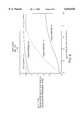
- FIG. 7shows the frequency and voltage curves obtained using the electronic bridge of the present invention, plotted using the same indications as those given for FIG. 4;
- FIG. 8shows the same frequency and voltage curves obtained firstly using the invention as shown in FIG. 7 and in dashed lines, and secondly using the assignee's prior art as shown in FIG. 4 and in solid lines, for the purposes of providing a better comparison.
- the apparatus 10includes a deformable support device proper 12, e.g. a mattress, comprising at least one closed or controlled-release chamber 14 that is flexible and inflatable.
- the chambermay be composed of a multitude of inflatable tubes that communicate with one another, said chamber 14 being inflatable under an adjustable predetermined initial inflation pressure.
- the chamber 14has a top face 15 serving to support the element to be supported, preferably patient P, and a bottom face 16 which may, for example, rest on a base (not shown) or on equivalent means.
- the apparatusfurther includes servo-control means 18 for servo-controlling the pressure at which the chamber 14 is filled as a function of the distance to which the element being supported penetrates into the support device.
- said servo-control meansmay comprise filling means 20, such as pumping means 20 for pumping a filling fluid into the chamber 14, such as a gas, in particular air, or a liquid, in particular water, and it may include emptying means such as a valve 22.
- filling means 20such as pumping means 20 for pumping a filling fluid into the chamber 14, such as a gas, in particular air, or a liquid, in particular water, and it may include emptying means such as a valve 22.
- the apparatusalso includes measurement means 30 for measuring the positioning D resulting from deformation of the top face 15 of the chamber versus its bottom face 16.
- the measurement means 30include a metal element 32, advantageously in the form of a flexible film of a thin metallic foil, movable and deformable in space by being linked to the top face 15 of the chamber 14, inside said chamber 14 in this example, said movement and deformation being caused by penetration of the volume and shape of said supported element, preferably a patient, in said deformable support device, preferably a mattress, said metallic foil cooperating with at least one inductive element 34 forming a position detector linked to the bottom face 16 of said chamber 14, which inductive element may be disposed inside the chamber 14, integrated into the bottom face of the chamber 16, or else it may secured to the outside of said bottom face 16 of the chamber 14, as shown.
- a metal element 32advantageously in the form of a flexible film of a thin metallic foil, movable and deformable in space by being linked to the top face 15 of the chamber 14, inside said chamber 14 in this example, said movement and deformation being caused by penetration of the volume and shape of said supported element, preferably a patient, in said deformable support device, preferably
- the apparatusalso includes control means 40 that act on the servo-control means 18 for servo-controlling he inflation pressure of the chamber 14 to ensure that, while the element is being supported, the positioning D of the top face 15 versus the bottom face 16 of the chamber 14 is kept preferably at a predetermined position value, e.g. an essentially constant value, i.e. a value essentially equal to a reference position D c , or within an acceptable range of variation there about.
- a predetermined position valuee.g. an essentially constant value, i.e. a value essentially equal to a reference position D c , or within an acceptable range of variation there about.
- the control means 40may advantageously include a control station 42 comprising an electronic or an electromechanical central processing unit having a memory, which unit continuously or intermittently receives signals that are proportional to the value of the measured position D m , and that are transmitted by the above-mentioned measurement means 30, and compares the measured values D m with the reference position value D c .
- the control station 42controls the servo-control means 20, 22 for servo-controlling the inflation pressure of the chamber 14 so that a measured position D m is obtained that is essentially constantly equal to the reference position D c or within an acceptable range of variation there about.
- the control means 40may include an oscillator device 44 shown in detail in FIG. 3 and coupled to the inductive element 34, such as an induction coil, an amplifier device 46 whose gain may be adjusted by a reference setting device 48 defining the reference position D c .
- the amplifier 46is then coupled to a proportional-plus-integral regulator device 50 coupled to a matching device 52 whose output is coupled to the control station 42.
- the inductive element 34such as an induction coil
- the inductive element 34is, for example, arranged on a reinforcing member 36 positioned in the vicinity of that region of the element being supported P which has the largest mass or which is most protuberant, namely the sacral region of the patient P in this example, as explained in the applicant's above-mentioned prior document, therefore the thin flexible metal foil 32 is also facing the sacral region of the patient P.
- the thickness of this foilis for example ranging between about 10 ⁇ m and 40 ⁇ m.
- FIG. 4shows the curves giving frequency and voltage as a function of the distance between the flexible thin metal foil 32 and the inductive element or coil 34 that are obtained with the applicant's prior apparatus, as shown in accompanying FIGS. 1 to 3. It can be observed that the value of the frequency varies as a function of distance over the range 5.5 kHz to 6.5 kHz approximately. This frequency variation is considerable because it is about 20% of the initial frequency, and it constitutes an interference phenomenon relative to the voltage value, it being desirable for the voltage value to be substantially proportional to distance. Furthermore, frequency variation might give rise to electromagnetic compatibility problems. Finally, with that prior solution, and as shown in FIG. 4, the variation of the voltage as a function of distance is relatively small since the voltage varies from 0.5 V initially to about 2.5 V for a distance variation of 10 cm, which gives rise to difficulties in processing the signal.
- the apparatusis modified so that the measurement device includes an impedance-varying element for measuring the position of the closest point of the supported element, namely in practice of the deformed foil 32, said impedance varying element being integrated in an electronic measurement bridge.
- the prior oscillator 44is modified and is given the reference number 544, and its outline is shown in dashed lines in FIG. 6.
- the prior measurement device 30is referenced 530 because it is an integral part of a measurement bridge 600 which is described in more detail below.
- the flexible thin metal foil elementwhich remains unchanged, is still referenced 32, and the prior inductive element at 34 is constituted more generally by an impedance-varying element referenced 534 which is integrated into the measurement bridge 600.
- the impedance-varying elementmay be chosen from the group consisting of: a resistive element, e.g. a conductive foam; a capacitive element, e.g. in which a flexible film of a thin metal foil which may be constituted by the flexible film of metal foil 32 is one of the components of the capacitor; an inductive element, in particular a measurement induction coil, as shown because it constitutes the currently preferred embodiment; and an element made up of any combination of the three above-mentioned basic elements.
- the vertices of the branches of the measurement bridgeare respectively referenced 1, 2, 3, and 4.
- the measurement element 534may be connected to the vertices 1 and 2.
- the vertex 1is connected to the vertex 4 via a branch including a first impedance Z1
- the vertex 4is connected to the vertex 3 via a branch which is situated opposite from the branch including the measurement element 534.
- this opposite branchpreferably includes a shielding induction coil 610 whose function is explained below.
- the vertex 3is connected to the vertex 2 via a branch including a second impedance Z2 in this example.
- the vertices 1 and 3 of the measurement bridgeare also connected to the amplifier 46, optionally via at least one decoupling capacitor C2.
- the oscillator 544is made up of a static portion constituted by the measurement bridge 600, the capacitors C16 and C17, and a dynamic portion constituted by the transistor Q2 and its bias elements, as can be well understood by a person skilled in the art.
- the dynamic portionis connected to the vertices 4 and 2 of the measurement bridge 600.
- the shielding induction coil 610is advantageously identical to the measurement induction coil 534 so that, when they are subjected to outside influences, e.g. caused by metal elements such as the bed, the shielding induction coil 610 and the measurement induction coil 534 vary identically.
- the two other branchespreferably have identical impedances Z1, Z2.
- the shielding induction coil 610with a second piece of metal foil 612 identical to the moving flexible film of thin metal foil 32, the second piece of metal foil 612 being arranged at a predetermined distance from the shielding induction coil 610.
- the shielding induction coil 610can be glued against the shielding induction coil 610 outside the measurement bridge, i.e. opposite from the measurement device 530.
- the bridge 600By means of this design of the measurement bridge, it is possible to set the bridge 600 to a zero value for a predetermined distance value, e.g. in the vicinity of zero, i.e. when the moving flexible film of thin metal foil 32 almost touches the induction coil 534.
- FIGS. 7 and 8show in dashed lines the curves giving frequency and voltage as a function of the distance between the closest point of the deformed metal foil 32 and the measurement induction coil 534 obtained with the design of the invention. It can be observed that the frequency is essentially constant so that the oscillator 544 has become an oscillator whose frequency is fixed under the operation conditions provided, in this example at about 6 kHz.
- the voltage curvevaries considerably as a function of position, from a zero value for a distance initially set at zero to a voltage of about 6.5 volts for a distance of 10 cm, which represents a difference of 6.5 volts compared with about 2.5 volts in the prior solution shown in solid lines in FIG. 4 and reproduced in FIG. 8.
- the fact that the metal foil is flexible and deformable in spaceis an important and critical feature since the deformation of the foil will correspond to the shape of the body and implies that the system provides a response which corresponds to the positioning of the body in the support as "seen" by the sensor in function of the morphology of the body and not only in function of a displacement closer or farther from the impedance-varying element like 534.
- FIGS. 5, 6, and 7form an integral part of the present invention and therefore of the description.
- any characteristic which results from the description and from the drawings, and which appears to be novel compared with any state of the artis part of the present invention in its function or general means.
Landscapes
- Physics & Mathematics (AREA)
- General Physics & Mathematics (AREA)
- Measurement Of Length, Angles, Or The Like Using Electric Or Magnetic Means (AREA)
- Invalid Beds And Related Equipment (AREA)
- General Induction Heating (AREA)
- Motor Or Generator Frames (AREA)
- Magnetically Actuated Valves (AREA)
- Electrotherapy Devices (AREA)
- Signal Processing For Digital Recording And Reproducing (AREA)
- Medicines Containing Antibodies Or Antigens For Use As Internal Diagnostic Agents (AREA)
- Transmission And Conversion Of Sensor Element Output (AREA)
- Testing Of Short-Circuits, Discontinuities, Leakage, Or Incorrect Line Connections (AREA)
- Measurement Of Resistance Or Impedance (AREA)
- Bridges Or Land Bridges (AREA)
Abstract
Description
Claims (20)
Applications Claiming Priority (2)
| Application Number | Priority Date | Filing Date | Title |
|---|---|---|---|
| FR9609205 | 1996-07-23 | ||
| FR9609205AFR2751743B1 (en) | 1996-07-23 | 1996-07-23 | SELF INTEGRATED METHOD AND DEVICE IN A MEASUREMENT BRIDGE |
Publications (1)
| Publication Number | Publication Date |
|---|---|
| US6034526Atrue US6034526A (en) | 2000-03-07 |
Family
ID=9494339
Family Applications (1)
| Application Number | Title | Priority Date | Filing Date |
|---|---|---|---|
| US08/898,487Expired - LifetimeUS6034526A (en) | 1996-07-23 | 1997-07-22 | Apparatus for controlling the inflation pressure of a mattress in response to deformation of the mattress using impedance measurement |
Country Status (10)
| Country | Link |
|---|---|
| US (1) | US6034526A (en) |
| EP (1) | EP0914588B1 (en) |
| JP (1) | JP2000514923A (en) |
| AT (1) | ATE308734T1 (en) |
| AU (1) | AU3852797A (en) |
| BR (1) | BR9710535A (en) |
| CA (1) | CA2258114A1 (en) |
| DE (1) | DE69734514T2 (en) |
| FR (1) | FR2751743B1 (en) |
| WO (1) | WO1998003835A1 (en) |
Cited By (36)
| Publication number | Priority date | Publication date | Assignee | Title |
|---|---|---|---|---|
| WO2000059346A1 (en)* | 1999-04-07 | 2000-10-12 | L & P Property Management Company | Customized mattress system |
| US6244272B1 (en) | 1996-07-24 | 2001-06-12 | Support Systems International Industries | Multilayer assembly with a central electrically conductive layer for use as an inductive sensor element |
| GB2387325A (en)* | 2002-03-14 | 2003-10-15 | Huntleigh Technology Plc | Inflatable support |
| US6721980B1 (en) | 1998-10-28 | 2004-04-20 | Hill-Fom Services, Inc. | Force optimization surface apparatus and method |
| US20050200489A1 (en)* | 2004-02-24 | 2005-09-15 | Sloop David J. | Cushion immersion sensor |
| US20050262638A1 (en)* | 2004-05-27 | 2005-12-01 | Jose Libunao | Inflatable, pressure alleviating, eggcrate mattress pad |
| WO2006116667A3 (en)* | 2005-04-27 | 2007-01-11 | Roho Inc | Proximity sensor |
| US20080005843A1 (en)* | 2004-04-30 | 2008-01-10 | Tactex Controls Inc. | Body Support Apparatus Having Automatic Pressure Control and Related Methods |
| US20100101022A1 (en)* | 2008-10-24 | 2010-04-29 | Carl William Riley | Apparatuses for supporting and monitoring a person |
| US7849545B2 (en) | 2006-11-14 | 2010-12-14 | Hill-Rom Industries Sa | Control system for hospital bed mattress |
| US20110068935A1 (en)* | 2009-09-18 | 2011-03-24 | Riley Carl W | Apparatuses for supporting and monitoring a condition of a person |
| WO2011089281A1 (en) | 2010-01-22 | 2011-07-28 | Fundacion Fatronik | Assistance device for a person wishing to stand up or sit down in a seating device |
| US8090478B2 (en) | 2005-06-10 | 2012-01-03 | Hill-Rom Services, Inc. | Control for pressurized bladder in a patient support apparatus |
| US8317776B2 (en) | 2007-12-18 | 2012-11-27 | The Invention Science Fund I, Llc | Circulatory monitoring systems and methods |
| US8409132B2 (en) | 2007-12-18 | 2013-04-02 | The Invention Science Fund I, Llc | Treatment indications informed by a priori implant information |
| US8458042B1 (en) | 2011-03-02 | 2013-06-04 | King Koil Licensing Company, Inc. | Methods for selecting a bedding mattress |
| US8636670B2 (en) | 2008-05-13 | 2014-01-28 | The Invention Science Fund I, Llc | Circulatory monitoring systems and methods |
| US8752220B2 (en) | 2009-07-10 | 2014-06-17 | Hill-Rom Services, Inc. | Systems for patient support, monitoring and treatment |
| US8844073B2 (en) | 2010-06-07 | 2014-09-30 | Hill-Rom Services, Inc. | Apparatus for supporting and monitoring a person |
| WO2015121822A1 (en) | 2014-02-14 | 2015-08-20 | Foampartner Fritz Nauer Ag | Mattress |
| US9165449B2 (en) | 2012-05-22 | 2015-10-20 | Hill-Rom Services, Inc. | Occupant egress prediction systems, methods and devices |
| US9333136B2 (en) | 2013-02-28 | 2016-05-10 | Hill-Rom Services, Inc. | Sensors in a mattress cover |
| US9468307B2 (en) | 2012-09-05 | 2016-10-18 | Stryker Corporation | Inflatable mattress and control methods |
| US20160317084A1 (en)* | 2015-04-29 | 2016-11-03 | Wellinks, Inc. | Sensor and Feedback Platform for Use in Orthotic and Prosthetic Devices |
| US9552460B2 (en) | 2009-09-18 | 2017-01-24 | Hill-Rom Services, Inc. | Apparatus for supporting and monitoring a person |
| US20170048965A1 (en)* | 2015-03-11 | 2017-02-16 | Seoul National University R&Db Foundation | Deformation sensing flexible substrate using pattern formed of conductive material |
| US9861550B2 (en) | 2012-05-22 | 2018-01-09 | Hill-Rom Services, Inc. | Adverse condition detection, assessment, and response systems, methods and devices |
| US9901499B2 (en) | 2014-01-29 | 2018-02-27 | Roho, Inc. | Cushion immersion sensor |
| EP3428675A1 (en) | 2017-07-12 | 2019-01-16 | Hill-Rom Services, Inc. | Patient support surface using radar |
| US10765577B2 (en) | 2015-06-30 | 2020-09-08 | Hill-Rom Services, Inc. | Microclimate system for a patient support apparatus |
| US10857051B2 (en) | 2017-02-16 | 2020-12-08 | Hill-Rom Services, Inc. | Occupant support and mattress with immersion sensing capability and methods of managing bladder pressure in the occupant support and mattress |
| US10912693B2 (en) | 2017-07-12 | 2021-02-09 | Hill-Rom Services, Inc. | Patient immersion and support surface life determination using RADAR and RFID |
| US11058227B2 (en) | 2015-04-23 | 2021-07-13 | Sealy Technology, Llc | Systems and methods for adjusting the firmness and profile of a mattress assembly |
| US20230355004A1 (en)* | 2022-05-05 | 2023-11-09 | Carilex Medical, Inc. | Smart mattress and control method thereof |
| US11877844B2 (en) | 2020-02-19 | 2024-01-23 | Hill-Rom Services, Inc. | Respiration detection using radar |
| US12042268B2 (en) | 2020-03-31 | 2024-07-23 | Hill-Rom Services, Inc. | Patient body monitoring using radar |
Families Citing this family (3)
| Publication number | Priority date | Publication date | Assignee | Title |
|---|---|---|---|---|
| JP2006208370A (en)* | 2004-12-28 | 2006-08-10 | Non-Destructive Inspection Co Ltd | Surface displacement measuring method and surface displacement measuring apparatus used for the same |
| FR2974988B1 (en) | 2011-05-12 | 2013-06-14 | Hill Rom Ind Sa | DEVICE FOR REGULATING MOISTURE AND TEMPERATURE AT THE SURFACE OF A SUPPORT ELEMENT |
| WO2023275824A1 (en)* | 2021-06-30 | 2023-01-05 | J. Brasch Co., Llc | Pressure-sensitive pad with calibration unit |
Citations (11)
| Publication number | Priority date | Publication date | Assignee | Title |
|---|---|---|---|---|
| DE2550427A1 (en)* | 1974-11-11 | 1976-05-13 | Kaman Sciences Corp | DISTANCE MEASURING SYSTEM AND METHOD OF MEASURING DISTANCES |
| EP0218301A2 (en)* | 1985-10-11 | 1987-04-15 | Auping B.V. | Mattress |
| US4797962A (en)* | 1986-11-05 | 1989-01-17 | Air Plus, Inc. | Closed loop feedback air supply for air support beds |
| US4833457A (en)* | 1987-11-23 | 1989-05-23 | Graebe Jr William F | Immersion control device and associated alarm system |
| EP0379694A2 (en)* | 1988-12-24 | 1990-08-01 | BSG-Schalttechnik GmbH & Co. KG | Device for converting position or pressure into electric variations |
| US4949412A (en)* | 1986-11-05 | 1990-08-21 | Air Plus, Inc. | Closed loop feedback air supply for air support beds |
| US5020176A (en)* | 1989-10-20 | 1991-06-04 | Angel Echevarria Co., Inc. | Control system for fluid-filled beds |
| DE4231616A1 (en)* | 1992-09-22 | 1994-03-24 | Seichter Gmbh | Capacitive sensor, esp. for distance measurement - has capacitive bridge circuit with electrode and supply surfaces on opposite sides of circuit board |
| DE9411493U1 (en)* | 1993-07-20 | 1994-11-10 | Linido B.V., Pijnacker | Mattress, especially suitable for the prevention of pressure ulcers |
| EP0676158A1 (en)* | 1994-04-06 | 1995-10-11 | Support Systems International Industries | Method and device for supporting the body of a patient allowing controlled sagging |
| US5850644A (en)* | 1995-08-22 | 1998-12-22 | Hsia; Yu Chun | Temperature and pressure control means for water bed |
- 1996
- 1996-07-23FRFR9609205Apatent/FR2751743B1/ennot_activeExpired - Fee Related
- 1997
- 1997-07-22EPEP97935594Apatent/EP0914588B1/ennot_activeExpired - Lifetime
- 1997-07-22DEDE69734514Tpatent/DE69734514T2/ennot_activeExpired - Lifetime
- 1997-07-22ATAT97935594Tpatent/ATE308734T1/ennot_activeIP Right Cessation
- 1997-07-22CACA002258114Apatent/CA2258114A1/ennot_activeAbandoned
- 1997-07-22JPJP10506658Apatent/JP2000514923A/enactivePending
- 1997-07-22WOPCT/FR1997/001358patent/WO1998003835A1/enactiveIP Right Grant
- 1997-07-22BRBR9710535Apatent/BR9710535A/ennot_activeIP Right Cessation
- 1997-07-22AUAU38527/97Apatent/AU3852797A/ennot_activeAbandoned
- 1997-07-22USUS08/898,487patent/US6034526A/ennot_activeExpired - Lifetime
Patent Citations (14)
| Publication number | Priority date | Publication date | Assignee | Title |
|---|---|---|---|---|
| DE2550427A1 (en)* | 1974-11-11 | 1976-05-13 | Kaman Sciences Corp | DISTANCE MEASURING SYSTEM AND METHOD OF MEASURING DISTANCES |
| US4160204A (en)* | 1974-11-11 | 1979-07-03 | Kaman Sciences Corporation | Non-contact distance measurement system |
| EP0218301A2 (en)* | 1985-10-11 | 1987-04-15 | Auping B.V. | Mattress |
| US4949412A (en)* | 1986-11-05 | 1990-08-21 | Air Plus, Inc. | Closed loop feedback air supply for air support beds |
| US4797962A (en)* | 1986-11-05 | 1989-01-17 | Air Plus, Inc. | Closed loop feedback air supply for air support beds |
| US4833457A (en)* | 1987-11-23 | 1989-05-23 | Graebe Jr William F | Immersion control device and associated alarm system |
| EP0379694A2 (en)* | 1988-12-24 | 1990-08-01 | BSG-Schalttechnik GmbH & Co. KG | Device for converting position or pressure into electric variations |
| US5020176A (en)* | 1989-10-20 | 1991-06-04 | Angel Echevarria Co., Inc. | Control system for fluid-filled beds |
| DE4231616A1 (en)* | 1992-09-22 | 1994-03-24 | Seichter Gmbh | Capacitive sensor, esp. for distance measurement - has capacitive bridge circuit with electrode and supply surfaces on opposite sides of circuit board |
| US5412327A (en)* | 1992-09-22 | 1995-05-02 | Meinen; Michael | Distance sensor utilizing a bridge circuit incorporating variable capacitances |
| DE9411493U1 (en)* | 1993-07-20 | 1994-11-10 | Linido B.V., Pijnacker | Mattress, especially suitable for the prevention of pressure ulcers |
| EP0676158A1 (en)* | 1994-04-06 | 1995-10-11 | Support Systems International Industries | Method and device for supporting the body of a patient allowing controlled sagging |
| US5560374A (en)* | 1994-04-06 | 1996-10-01 | Hill-Rom, Inc. | Patient support apparatus and method |
| US5850644A (en)* | 1995-08-22 | 1998-12-22 | Hsia; Yu Chun | Temperature and pressure control means for water bed |
Non-Patent Citations (2)
| Title |
|---|
| Journal de l Equipement Electrique et Electronique, No. 306, Nov. 1970, pp. 116 117, XP002027296, Conception et Develloppement De Capteurs De Proximite .* |
| Journal de l'Equipement Electrique et Electronique, No. 306, Nov. 1970, pp. 116-117, XP002027296, Conception et Develloppement De Capteurs De Proximite. |
Cited By (80)
| Publication number | Priority date | Publication date | Assignee | Title |
|---|---|---|---|---|
| US6244272B1 (en) | 1996-07-24 | 2001-06-12 | Support Systems International Industries | Multilayer assembly with a central electrically conductive layer for use as an inductive sensor element |
| US7515059B2 (en) | 1998-10-28 | 2009-04-07 | Hill-Rom Services, Inc. | Patient support surface with physiological sensors |
| US6721980B1 (en) | 1998-10-28 | 2004-04-20 | Hill-Fom Services, Inc. | Force optimization surface apparatus and method |
| US20040194220A1 (en)* | 1998-10-28 | 2004-10-07 | Hill-Rom Services, Inc. | Force optimization surface apparatus and method |
| US8031080B2 (en) | 1998-10-28 | 2011-10-04 | Hill-Rom Services, Inc. | Patient support surface with vital signs sensors |
| US20090183312A1 (en)* | 1998-10-28 | 2009-07-23 | Price James H | Patient support surface with vital signs sensors |
| US7330127B2 (en) | 1998-10-28 | 2008-02-12 | Hill-Rom Services, Inc. | Force optimization surface apparatus and method |
| US20080060138A1 (en)* | 1998-10-28 | 2008-03-13 | Price James H | Patient support surface with physiological sensors |
| US6585328B1 (en) | 1999-04-07 | 2003-07-01 | L&P Property Management Company | Customized mattress evaluation system |
| WO2000059346A1 (en)* | 1999-04-07 | 2000-10-12 | L & P Property Management Company | Customized mattress system |
| GB2387325A (en)* | 2002-03-14 | 2003-10-15 | Huntleigh Technology Plc | Inflatable support |
| GB2387325B (en)* | 2002-03-14 | 2004-05-19 | Huntleigh Technology Plc | Inflatable support |
| US20050200489A1 (en)* | 2004-02-24 | 2005-09-15 | Sloop David J. | Cushion immersion sensor |
| US7685658B2 (en)* | 2004-04-30 | 2010-03-30 | Nitta Corporation | Body support apparatus having automatic pressure control and related methods |
| US20080005843A1 (en)* | 2004-04-30 | 2008-01-10 | Tactex Controls Inc. | Body Support Apparatus Having Automatic Pressure Control and Related Methods |
| US20050262638A1 (en)* | 2004-05-27 | 2005-12-01 | Jose Libunao | Inflatable, pressure alleviating, eggcrate mattress pad |
| US8698509B2 (en) | 2005-04-27 | 2014-04-15 | Roho, Inc. | Proximity sensor |
| US20110209287A1 (en)* | 2005-04-27 | 2011-09-01 | Roho, Inc. | Proximity sensor |
| WO2006116667A3 (en)* | 2005-04-27 | 2007-01-11 | Roho Inc | Proximity sensor |
| US8090478B2 (en) | 2005-06-10 | 2012-01-03 | Hill-Rom Services, Inc. | Control for pressurized bladder in a patient support apparatus |
| US9107511B2 (en) | 2005-06-10 | 2015-08-18 | Hill-Rom Services, Inc. | Control for pressurized bladder in a patient support apparatus |
| US8620477B2 (en) | 2005-06-10 | 2013-12-31 | Hill-Rom Services, Inc. | Control for pressurized bladder in a patient support apparatus |
| US7849545B2 (en) | 2006-11-14 | 2010-12-14 | Hill-Rom Industries Sa | Control system for hospital bed mattress |
| US9717896B2 (en) | 2007-12-18 | 2017-08-01 | Gearbox, Llc | Treatment indications informed by a priori implant information |
| US8317776B2 (en) | 2007-12-18 | 2012-11-27 | The Invention Science Fund I, Llc | Circulatory monitoring systems and methods |
| US8403881B2 (en) | 2007-12-18 | 2013-03-26 | The Invention Science Fund I, Llc | Circulatory monitoring systems and methods |
| US8409132B2 (en) | 2007-12-18 | 2013-04-02 | The Invention Science Fund I, Llc | Treatment indications informed by a priori implant information |
| US8870813B2 (en) | 2007-12-18 | 2014-10-28 | The Invention Science Fund I, Llc | Circulatory monitoring systems and methods |
| US8636670B2 (en) | 2008-05-13 | 2014-01-28 | The Invention Science Fund I, Llc | Circulatory monitoring systems and methods |
| US20100101022A1 (en)* | 2008-10-24 | 2010-04-29 | Carl William Riley | Apparatuses for supporting and monitoring a person |
| US8281433B2 (en) | 2008-10-24 | 2012-10-09 | Hill-Rom Services, Inc. | Apparatuses for supporting and monitoring a person |
| US8752220B2 (en) | 2009-07-10 | 2014-06-17 | Hill-Rom Services, Inc. | Systems for patient support, monitoring and treatment |
| US9044204B2 (en) | 2009-09-18 | 2015-06-02 | Hill-Rom Services, Inc. | Apparatuses for supporting and monitoring a condition of a person |
| US9552460B2 (en) | 2009-09-18 | 2017-01-24 | Hill-Rom Services, Inc. | Apparatus for supporting and monitoring a person |
| US8525679B2 (en) | 2009-09-18 | 2013-09-03 | Hill-Rom Services, Inc. | Sensor control for apparatuses for supporting and monitoring a person |
| US8525680B2 (en) | 2009-09-18 | 2013-09-03 | Hill-Rom Services, Inc. | Apparatuses for supporting and monitoring a condition of a person |
| US20110068935A1 (en)* | 2009-09-18 | 2011-03-24 | Riley Carl W | Apparatuses for supporting and monitoring a condition of a person |
| US10583058B2 (en) | 2009-09-18 | 2020-03-10 | Hill-Rom Services, Inc. | Person support apparatus having physiological sensor |
| US9013315B2 (en) | 2009-09-18 | 2015-04-21 | Hill-Rom Services, Inc. | Sensor control for apparatuses for supporting and monitoring a person |
| US9775758B2 (en) | 2009-09-18 | 2017-10-03 | Hill-Rom Services, Inc. | Person support apparatus having physiological sensor |
| US20110068928A1 (en)* | 2009-09-18 | 2011-03-24 | Riley Carl W | Sensor control for apparatuses for supporting and monitoring a person |
| US10111794B2 (en) | 2009-09-18 | 2018-10-30 | Hill-Rom Services, Inc. | Person support apparatus having physiological sensor |
| US9549675B2 (en) | 2009-09-18 | 2017-01-24 | Hill-Rom Services, Inc. | Sensor control for apparatuses for supporting and monitoring a person |
| US9549705B2 (en) | 2009-09-18 | 2017-01-24 | Hill-Rom Services, Inc. | Apparatuses for supporting and monitoring a condition of a person |
| WO2011089281A1 (en) | 2010-01-22 | 2011-07-28 | Fundacion Fatronik | Assistance device for a person wishing to stand up or sit down in a seating device |
| US8844073B2 (en) | 2010-06-07 | 2014-09-30 | Hill-Rom Services, Inc. | Apparatus for supporting and monitoring a person |
| US8676662B1 (en) | 2011-03-02 | 2014-03-18 | King Koil Licensing Company, Inc. | System and method for selecting a bedding mattress |
| US9135651B2 (en) | 2011-03-02 | 2015-09-15 | King Koil Licensing Company, Inc. | System and method for selecting a bedding mattress |
| US8458042B1 (en) | 2011-03-02 | 2013-06-04 | King Koil Licensing Company, Inc. | Methods for selecting a bedding mattress |
| US9978244B2 (en) | 2012-05-22 | 2018-05-22 | Hill-Rom Services, Inc. | Occupant falls risk determination systems, methods and devices |
| US9861550B2 (en) | 2012-05-22 | 2018-01-09 | Hill-Rom Services, Inc. | Adverse condition detection, assessment, and response systems, methods and devices |
| US9552714B2 (en) | 2012-05-22 | 2017-01-24 | Hill-Rom Services, Inc. | Occupant egress prediction systems, methods and devices |
| US9761109B2 (en) | 2012-05-22 | 2017-09-12 | Hill-Rom Services, Inc. | Occupant egress prediction systems, methods and devices |
| US9165449B2 (en) | 2012-05-22 | 2015-10-20 | Hill-Rom Services, Inc. | Occupant egress prediction systems, methods and devices |
| US9468307B2 (en) | 2012-09-05 | 2016-10-18 | Stryker Corporation | Inflatable mattress and control methods |
| US10682273B2 (en) | 2012-09-05 | 2020-06-16 | Stryker Corporation | Inflatable mattress and control methods |
| US11413202B2 (en) | 2012-09-05 | 2022-08-16 | Stryker Corporation | Inflatable mattress and control methods |
| US12023287B2 (en) | 2012-09-05 | 2024-07-02 | Stryker Corporation | Inflatable mattress and control methods |
| US9333136B2 (en) | 2013-02-28 | 2016-05-10 | Hill-Rom Services, Inc. | Sensors in a mattress cover |
| US11684529B2 (en) | 2013-02-28 | 2023-06-27 | Hill-Rom Services, Inc. | Mattress cover sensor method |
| US9901499B2 (en) | 2014-01-29 | 2018-02-27 | Roho, Inc. | Cushion immersion sensor |
| WO2015121822A1 (en) | 2014-02-14 | 2015-08-20 | Foampartner Fritz Nauer Ag | Mattress |
| US9699894B2 (en)* | 2015-03-11 | 2017-07-04 | Seoul National University R&Db Foundation | Deformation sensing flexible substrate using pattern formed of conductive material |
| US20170048965A1 (en)* | 2015-03-11 | 2017-02-16 | Seoul National University R&Db Foundation | Deformation sensing flexible substrate using pattern formed of conductive material |
| US11058227B2 (en) | 2015-04-23 | 2021-07-13 | Sealy Technology, Llc | Systems and methods for adjusting the firmness and profile of a mattress assembly |
| US11910929B2 (en) | 2015-04-23 | 2024-02-27 | Sealy Technology, Llc | Systems and methods for adjusting the firmness and profile of a mattress assembly |
| US20160317084A1 (en)* | 2015-04-29 | 2016-11-03 | Wellinks, Inc. | Sensor and Feedback Platform for Use in Orthotic and Prosthetic Devices |
| US10765577B2 (en) | 2015-06-30 | 2020-09-08 | Hill-Rom Services, Inc. | Microclimate system for a patient support apparatus |
| US10857051B2 (en) | 2017-02-16 | 2020-12-08 | Hill-Rom Services, Inc. | Occupant support and mattress with immersion sensing capability and methods of managing bladder pressure in the occupant support and mattress |
| US10912693B2 (en) | 2017-07-12 | 2021-02-09 | Hill-Rom Services, Inc. | Patient immersion and support surface life determination using RADAR and RFID |
| US11253411B2 (en) | 2017-07-12 | 2022-02-22 | Hill-Rom Services, Inc. | Patient support system control using radar |
| US10813809B2 (en) | 2017-07-12 | 2020-10-27 | Hill-Rom Services, Inc. | Patient immersion sensor using radar |
| EP3690474A1 (en) | 2017-07-12 | 2020-08-05 | Hill-Rom Services, Inc. | Patient support surface using radar |
| US11938072B2 (en) | 2017-07-12 | 2024-03-26 | Hill-Rom Services, Inc. | Patient support apparatus having a radar system |
| EP3428675A1 (en) | 2017-07-12 | 2019-01-16 | Hill-Rom Services, Inc. | Patient support surface using radar |
| US12193982B2 (en) | 2017-07-12 | 2025-01-14 | Hill-Rom Services, Inc. | Patient support apparatus having a radar system |
| US11877844B2 (en) | 2020-02-19 | 2024-01-23 | Hill-Rom Services, Inc. | Respiration detection using radar |
| US12220229B2 (en) | 2020-02-19 | 2025-02-11 | Hill-Rom Services, Inc. | Radar sensors for patient monitoring |
| US12042268B2 (en) | 2020-03-31 | 2024-07-23 | Hill-Rom Services, Inc. | Patient body monitoring using radar |
| US20230355004A1 (en)* | 2022-05-05 | 2023-11-09 | Carilex Medical, Inc. | Smart mattress and control method thereof |
Also Published As
| Publication number | Publication date |
|---|---|
| ATE308734T1 (en) | 2005-11-15 |
| FR2751743B1 (en) | 1998-10-23 |
| AU3852797A (en) | 1998-02-10 |
| DE69734514T2 (en) | 2006-07-27 |
| WO1998003835A1 (en) | 1998-01-29 |
| FR2751743A1 (en) | 1998-01-30 |
| CA2258114A1 (en) | 1998-01-29 |
| BR9710535A (en) | 1999-08-17 |
| DE69734514D1 (en) | 2005-12-08 |
| JP2000514923A (en) | 2000-11-07 |
| EP0914588B1 (en) | 2005-11-02 |
| EP0914588A1 (en) | 1999-05-12 |
Similar Documents
| Publication | Publication Date | Title |
|---|---|---|
| US6034526A (en) | Apparatus for controlling the inflation pressure of a mattress in response to deformation of the mattress using impedance measurement | |
| US4281666A (en) | Single diaphragm pressure-balanced telemetric pressure sensing system | |
| US4127110A (en) | Implantable pressure transducer | |
| US4660568A (en) | Telemetric differential pressure sensing system and method therefore | |
| US4653508A (en) | Pressure-balanced telemetric pressure sensing system and method therefore | |
| US4206761A (en) | Pressure-balanced telemetric pressure sensing method | |
| US4658651A (en) | Wheatstone bridge-type transducers with reduced thermal shift | |
| US4016764A (en) | Temperature compensated, high resolution pressure transducer based on capacitance change principles | |
| US4281667A (en) | Single diaphragm telemetric differential pressure sensing system | |
| US4331133A (en) | Pressure measurement apparatus | |
| US4206762A (en) | Telemetric differential pressure sensing method | |
| US5560374A (en) | Patient support apparatus and method | |
| US5291899A (en) | Method and device for measuring intracranial pressure | |
| JP3532573B2 (en) | Pressure transmitter with remote seal diaphragm | |
| AU2002219098A1 (en) | Method and device for determining and/or monitoring the level of a medium in a container, or for determining the density of a medium in a container | |
| JP2007307393A (en) | Method and apparatus for supporting element to be supported, in particular body of patient for maintaining it at predetermined float line | |
| US5877423A (en) | Method for providing temperature compensation for a wheatstone bridge-type pressure sensor | |
| EP0740781A1 (en) | Static pressure compensation of resonant integrated microbeam sensors | |
| US4704902A (en) | Acoustical volume/pressure measurement device | |
| DE3570284D1 (en) | Transducer for the electrical measurement of forces, torques, accelerations, pressures and mechanical stresses | |
| US11864919B1 (en) | Calibrating passive LC sensor | |
| US4492234A (en) | Pressure measurement method | |
| EP0391880A2 (en) | Measurement and control of magnetostrictive transducer motion | |
| Zervas et al. | A pressure-balanced radio-telemetry system for the measurement of intracranial pressure: A preliminary design report | |
| JPH0141330B2 (en) |
Legal Events
| Date | Code | Title | Description |
|---|---|---|---|
| AS | Assignment | Owner name:SUPPORT SYSTEMS INTERNATIONAL INDUSTRIES, FRANCE Free format text:ASSIGNMENT OF ASSIGNORS INTEREST;ASSIGNORS:MONTANT, JEAN-MARC;CAMINADE, JEAN-LUC;REEL/FRAME:009896/0019 Effective date:19970623 | |
| FEPP | Fee payment procedure | Free format text:PAYOR NUMBER ASSIGNED (ORIGINAL EVENT CODE: ASPN); ENTITY STATUS OF PATENT OWNER: LARGE ENTITY | |
| STCF | Information on status: patent grant | Free format text:PATENTED CASE | |
| AS | Assignment | Owner name:HILL-ROM INDUSTRIES S.A., FRANCE Free format text:CHANGE OF NAME;ASSIGNOR:SUPPORT SYSTEMS INTERNATIONAL INDUSTRIES;REEL/FRAME:011019/0588 Effective date:19990430 | |
| FEPP | Fee payment procedure | Free format text:PAYER NUMBER DE-ASSIGNED (ORIGINAL EVENT CODE: RMPN); ENTITY STATUS OF PATENT OWNER: LARGE ENTITY Free format text:PAYOR NUMBER ASSIGNED (ORIGINAL EVENT CODE: ASPN); ENTITY STATUS OF PATENT OWNER: LARGE ENTITY | |
| FEPP | Fee payment procedure | Free format text:PAYER NUMBER DE-ASSIGNED (ORIGINAL EVENT CODE: RMPN); ENTITY STATUS OF PATENT OWNER: LARGE ENTITY Free format text:PAYOR NUMBER ASSIGNED (ORIGINAL EVENT CODE: ASPN); ENTITY STATUS OF PATENT OWNER: LARGE ENTITY | |
| FEPP | Fee payment procedure | Free format text:PAYER NUMBER DE-ASSIGNED (ORIGINAL EVENT CODE: RMPN); ENTITY STATUS OF PATENT OWNER: LARGE ENTITY Free format text:PAYOR NUMBER ASSIGNED (ORIGINAL EVENT CODE: ASPN); ENTITY STATUS OF PATENT OWNER: LARGE ENTITY | |
| FEPP | Fee payment procedure | Free format text:PAYER NUMBER DE-ASSIGNED (ORIGINAL EVENT CODE: RMPN); ENTITY STATUS OF PATENT OWNER: LARGE ENTITY Free format text:PAYOR NUMBER ASSIGNED (ORIGINAL EVENT CODE: ASPN); ENTITY STATUS OF PATENT OWNER: LARGE ENTITY | |
| FPAY | Fee payment | Year of fee payment:4 | |
| FPAY | Fee payment | Year of fee payment:8 | |
| FPAY | Fee payment | Year of fee payment:12 |