US6034361A - System for monitoring the progress of a chemical reaction in a microwave-assisted heating system - Google Patents
System for monitoring the progress of a chemical reaction in a microwave-assisted heating systemDownload PDFInfo
- Publication number
- US6034361A US6034361AUS09/300,492US30049299AUS6034361AUS 6034361 AUS6034361 AUS 6034361AUS 30049299 AUS30049299 AUS 30049299AUS 6034361 AUS6034361 AUS 6034361A
- Authority
- US
- United States
- Prior art keywords
- energy
- microwave
- waveguide
- sample
- reaction vessel
- Prior art date
- Legal status (The legal status is an assumption and is not a legal conclusion. Google has not performed a legal analysis and makes no representation as to the accuracy of the status listed.)
- Expired - Fee Related
Links
- 238000006243chemical reactionMethods0.000titleclaimsabstractdescription91
- 238000012544monitoring processMethods0.000titleclaimsabstractdescription11
- 238000010438heat treatmentMethods0.000titleabstractdescription23
- 238000012806monitoring deviceMethods0.000claimsabstractdescription19
- 230000005855radiationEffects0.000claimsabstractdescription12
- 238000002360preparation methodMethods0.000claimsabstractdescription9
- 239000000523sampleSubstances0.000description45
- 238000000034methodMethods0.000description12
- 238000003786synthesis reactionMethods0.000description10
- 239000003153chemical reaction reagentSubstances0.000description7
- 239000002904solventSubstances0.000description7
- 230000015572biosynthetic processEffects0.000description4
- 239000006096absorbing agentSubstances0.000description3
- 238000010521absorption reactionMethods0.000description3
- 230000007423decreaseEffects0.000description3
- 239000007788liquidSubstances0.000description3
- 238000007144microwave assisted synthesis reactionMethods0.000description3
- 239000007787solidSubstances0.000description3
- 238000004458analytical methodMethods0.000description2
- 230000008859changeEffects0.000description2
- 238000011161developmentMethods0.000description2
- 230000018109developmental processEffects0.000description2
- 238000000605extractionMethods0.000description2
- 239000000463materialSubstances0.000description2
- 238000005259measurementMethods0.000description2
- 238000012552reviewMethods0.000description2
- XLYOFNOQVPJJNP-UHFFFAOYSA-NwaterSubstancesOXLYOFNOQVPJJNP-UHFFFAOYSA-N0.000description2
- 239000011358absorbing materialSubstances0.000description1
- 239000003463adsorbentSubstances0.000description1
- 238000013459approachMethods0.000description1
- 230000009286beneficial effectEffects0.000description1
- 230000008901benefitEffects0.000description1
- 238000009529body temperature measurementMethods0.000description1
- 239000006227byproductSubstances0.000description1
- 230000015556catabolic processEffects0.000description1
- 239000000470constituentSubstances0.000description1
- 238000010276constructionMethods0.000description1
- 238000006731degradation reactionMethods0.000description1
- 238000013461designMethods0.000description1
- 238000001514detection methodMethods0.000description1
- 230000029087digestionEffects0.000description1
- 238000004821distillationMethods0.000description1
- 230000000694effectsEffects0.000description1
- 238000003780insertionMethods0.000description1
- 230000037431insertionEffects0.000description1
- 238000000874microwave-assisted extractionMethods0.000description1
- 238000012986modificationMethods0.000description1
- 230000004048modificationEffects0.000description1
- 238000006053organic reactionMethods0.000description1
- 239000000123paperSubstances0.000description1
- 239000000843powderSubstances0.000description1
- 239000000047productSubstances0.000description1
- 230000001737promoting effectEffects0.000description1
- 238000000746purificationMethods0.000description1
- 239000000376reactantSubstances0.000description1
- 239000011541reaction mixtureSubstances0.000description1
- 230000035484reaction timeEffects0.000description1
- 230000003252repetitive effectEffects0.000description1
- 238000005070samplingMethods0.000description1
- 238000000926separation methodMethods0.000description1
- 239000000126substanceSubstances0.000description1
Images


Classifications
- H—ELECTRICITY
- H05—ELECTRIC TECHNIQUES NOT OTHERWISE PROVIDED FOR
- H05B—ELECTRIC HEATING; ELECTRIC LIGHT SOURCES NOT OTHERWISE PROVIDED FOR; CIRCUIT ARRANGEMENTS FOR ELECTRIC LIGHT SOURCES, IN GENERAL
- H05B6/00—Heating by electric, magnetic or electromagnetic fields
- H05B6/64—Heating using microwaves
- H05B6/80—Apparatus for specific applications
- H05B6/806—Apparatus for specific applications for laboratory use
- B—PERFORMING OPERATIONS; TRANSPORTING
- B01—PHYSICAL OR CHEMICAL PROCESSES OR APPARATUS IN GENERAL
- B01J—CHEMICAL OR PHYSICAL PROCESSES, e.g. CATALYSIS OR COLLOID CHEMISTRY; THEIR RELEVANT APPARATUS
- B01J19/00—Chemical, physical or physico-chemical processes in general; Their relevant apparatus
- B01J19/08—Processes employing the direct application of electric or wave energy, or particle radiation; Apparatus therefor
- B01J19/12—Processes employing the direct application of electric or wave energy, or particle radiation; Apparatus therefor employing electromagnetic waves
- B01J19/122—Incoherent waves
- B01J19/126—Microwaves
Definitions
- the present inventionrelates generally to methods and apparatus for heating one or more constituent components in a sample and, more particularly, to a microwave-assisted heating system for promoting a chemical reaction of interest in a chemical synthesis.
- microwave heatingit is known in the art to use microwave heating to promote the progress of one or more sample preparation steps or of one or more chemical synthesis steps.
- microwave heating of chemical reactions in sealed containers to promote an organic reactionwas described by Giguere et al., in "The use of microwave ovens for rapid organic synthesis", Tetrahedron Letters 27: 279 (1986).
- Early studiesshowed that microwave heating can promote the progress of a chemical reaction and offers a dramatic decrease in reaction time.
- Those findingsstimulated the study of microwave heating, and advances in the field are described in several reviews (such as in Abramovitch, R. A., "Applications Of Microwave Energy in Organic Chemistry, A Review", Organic Preparations Procedures International 23:683-711.)
- microwave-assisted synthesisoffers fast synthesis procedures while offering better yields and improved selectivity.
- Developments in microwave-assisted synthesis and extraction techniquesaid in the generation and extraction of complex reaction mixtures.
- Microwave-assisted synthesisallows fast product generation in high yield under uniform conditions, and is considered to be well suited for performing combinatorial chemistry.
- the conventional microwave-assisted heating apparatustypically employs a microwave energy source, usually a magnetron or traveling wave tube source, coupled to a waveguide which serves to guide microwave energy in a forward direction to a container that contains a sample that is to be subjected to microwave-assisted heating.
- a microwave energy sourceusually a magnetron or traveling wave tube source
- a waveguidewhich serves to guide microwave energy in a forward direction to a container that contains a sample that is to be subjected to microwave-assisted heating.
- thermocouplestemperature probes, pressure probes, and similarly invasive devices, which may not be compatible with an applied microwave field.
- Instrumentsare typically employed for monitoring the state of the chemical reaction by observing the temperature, color, pH, viscosity, and the like of the material subject to the reaction.
- the present inventionprovides a system for monitoring the progress of a chemical reaction in a microwave-assisted heating, having a microwave energy source, a waveguide coupled to the microwave energy source and having a waveguide cavity, and a resistive load coupled to the waveguide, wherein the sample that is to be subject to microwave-assisted heating is situated in a reaction vessel which in turn is situated in a container subassembly located in the waveguide cavity, and wherein the waveguide geometry is arranged such that the reaction vessel is located at a predetermined position in the path of the forward microwave radiation between the microwave energy source and the resistive load.
- a directional coupler and an energy monitoring deviceis interposed between the reaction vessel and the resistive load so as to monitor the energy not absorbed by the reaction vessel.
- the energy absorbed by the samplemay be calculated in accordance with the level of energy measured by the energy monitoring device to provide a value that indicates the status of the chemical reaction. For example, as the chemical reaction proceeds from a first stage to a second stage, the level of energy absorbed by the sample will change. This change in absorbed energy level is monitored so as to provide a measure of the progress of the chemical reaction between the first stage and the second stage.
- the waveguide geometry of the systemis arranged such that the reaction vessel is located at a predetermined position in the path of the forward microwave radiation between the microwave energy source and a terminal end of the waveguide.
- An isolator provided in the form of a circulator coupled to the resistive loadis located at a predetermined position in the path of the forward microwave radiation between the microwave energy source and the reaction vessel so as to allow the forward energy generated by the energy source to proceed to the sample, and divert reverse energy (i.e., energy reflected from the reaction vessel, the sample, and the terminal end of the waveguide) to the resistive load.
- Forward energy and reverse energy monitoring devicesare interposed between the isolator and the reaction vessel so as measure respective forward energy and reverse energy levels. The energy absorbed by the sample may be calculated in accordance with the difference in the levels of energy measured by the forward energy and reverse energy monitoring devices to provide a value that indicates the status of the chemical reaction.
- the contemplated systemoffers the ability to accurately monitor the progress of a chemical reaction of differing quantities and types of samples by calculating the power absorbed by a sample present in the reaction vessel in accordance with the level of energy measured by the energy monitoring device(s), and is useable without major modifications when such differing quantities or types of samples are to be subjected to microwave-assisted heating.
- the samplecontains components that are absorptive of microwave radiation, such as water or other polar molecules
- the samplewill absorb nearly all of the radiated microwave energy and little of the radiated microwave energy will reach the resistive load. If, however, the sample is generally a poor absorber of microwave energy, the radiated microwave energy will pass through the reaction vessel, which absorbs little or none of the radiated microwave energy, such that the remaining radiated energy reaches the resistive load and is dissipated with an insignificant amount of power reflected back to the microwave energy source.
- the usermay thus employ contemplated system for effecting controlled microwave-assisted heating of a large number of samples, and may perform the relevant sample preparation steps, chemical synthesis procedures, or the like, in an accurate, simple, and cost-effective manner. These attributes are especially beneficial when the system is used for the type of repetitive heating procedures that are typically performed in one or more chemical analysis or a chemical synthesis applications.
- the contemplated systemmay be constructed to function in a lightweight and portable instrument that can be used in the field without reliance upon the typical attributes of a laboratory. Although the contemplated system may be usefully deployed outside of the laboratory, it nonetheless is amenable to use with any integrated analytical or synthesis instrument, whether that instrument is also field-portable, located in a vehicle, or maintained in a laboratory.
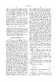
- FIG. 1is a simplified schematic representation of a first preferred embodiment of a system for microwave-assisted heating made in accordance with the present invention and having been preloaded with a reaction vessel having therein a sample that is to be subjected to a chemical reaction by way of a microwave-assisted heating process.
- FIG. 2is a simplified schematic representation of a second preferred embodiment of the system of FIG. 1.
- a first preferred embodiment of a microwave-assisted heating system 100may be constructed according to the present invention to include: a microwave energy source 101; a first directional coupler 102 connected between the microwave energy source 101 and a waveguide 106 so as to introduce microwave radiation in a positive, or forward, radiated direction 120 into a waveguide cavity 107; an energy monitoring device 112 connected to the first directional coupler 102 to measure the total power provided to the cavity by the source 101; a sample 103 in a reaction vessel 104, the latter preferably provided in the form of a reaction vessel suitable for use in one or more microwave-assisted chemical synthesis procedures; a container subassembly 105 preferably constructed of material that is substantially transparent to microwave energy, wherein the container subassembly 105 is situated in the cavity 107 so as to locate the reaction vessel 104 at a first predetermined location with respect to the geometry of the waveguide 106; a second directional coupler 108 interposed in the waveguide 106 at a
- the second directional coupler 108is connected to a forward energy monitoring device 109.
- the combination of the second directional coupler 108 and the forward energy monitoring device 109allow detection of the forward energy present in the cavity 107 at a point between the reaction vessel 104 and the resistive load 110.
- the resistive load 110functions to minimize the return of any microwave energy traveling in a negative, or reverse, radiated direction 121 which otherwise would have been reflected from a terminal end 111 of the waveguide 106.
- the energy proceeding in the forward radiated direction 120 in the vicinity of the second directional coupler 108may be understood to be forward radiated energy not otherwise absorbed by the combination of the sample 103, reaction vessel 104, and subassembly 105.
- the construction of the waveguide 106 and the location of the associated components heretofore described, which is described herein as the "geometry" of the system 100,is preferably tuned such that the resistive load 110 is matched to the waveguide 106.
- the location of reaction vessel 104 within the cavity 107is preferably consistent with a maximum field potential within the waveguide 106.
- the resistive load 110provides a sufficient load at all times to the microwave energy source 101 so as to promote stable operation of the microwave energy source 101 and to prevent self-destruction of the microwave energy source 101 (which would otherwise occur if the energy source 101 were to be improperly loaded).
- the sample 103contains reactants that are absorptive of microwave radiation, such as water or other polar molecules, the sample 103 will absorb nearly all of the forward-radiated microwave energy traveling in the forward radiated direction 108A and little of the forward-radiated microwave energy will reach the resistive load 110.
- the sample 103is generally a poor absorber of microwave energy and accordingly absorbs little or none of the forward-radiated microwave energy, most of the forward-radiated microwave energy will pass through the reaction vessel 104 and is coupled to the resistive load 110 so as to be dissipated, whereupon an insignificant amount of forward-radiated power can be reflected back in the reverse radiated direction 108B to the microwave energy source 101.
- the illustrated embodiment of the contemplated system 100provides microwave-assisted preparation of a variety of quantities and types of sample without resort to the use of a waveguide isolator.
- the power absorbed by the combination of the reaction vessel 104, the subassembly 105, and the sample 103may be calculated as follows, wherein the sample 103 contains a solvent only, and:
- P1the total power provided to the cavity by the source 101
- P2the power reflected by the combination of the sample 103, reaction vessel 104, and subassembly 105 in the reverse radiated direction 121;
- P3the power absorbed by the combination of the sample 103, reaction vessel 104, and subassembly 105;
- P4the powered measured by the energy monitoring device 109 (that is, the forward energy present in the cavity 107 at a point between the reaction vessel 104 and the resistive load 110);
- P1', P2', P3', P4'powers measured or absorbed according to respective foregoing descriptions of P1, P2, P3, P4 but with the exception that the sample contains a solvent plus reagents.
- P4' and P4are quantities measured by the energy monitoring device 109;
- P3can be measured by a rate study through application of microwave power and temperature measurement and by knowledge of the specific heat and volume of the solvent present in the reaction vessel 104. It is contemplated that P3 is measured over the identical synthesis time and power conditions for the particular reaction of interest. From the foregoing computations, the power absorbed by the sample 103 can be calculated. The absorbed power may be measured as a function of time while the reaction is ongoing (i.e., dynamically) or simply summed to provide a value representative of the total energy absorbed during the reaction.
- the progress of a chemical reactionmay be monitored by measuring the power absorption dynamic indicated by the changing value of P3.
- the initial power absorbed by the samplewill be a certain value which will be seen to decrease with time it has the absorbing species are converted to non-absorbing species.
- the progress of the reactioncan be monitored. A plot of such power absorbed versus time would resemble a declining exponential which decreases as the absorbing species are consumed.
- a second preferred embodiment 200 of the present inventionmay be constructed to include an isolator provided in the form of a circulator 130 coupled to the resistive load 110.
- the circulator 130is located within the waveguide 106 so as to allow the forward energy 120 generated by the energy source 101 to proceed to the sample 103, and to divert reverse energy 121 (i.e., energy not otherwise absorbed by the reaction vessel 104, the sample 103, the subassembly 105, and the terminal end of the waveguide 111) to the resistive load 110.
- Directional couplers 140are interposed between the circulator 130 and the reaction vessel 104 so as to couple the forward and reverse energy present in the vicinity of the directional couplers 140 respectively to a forward energy monitoring device 142 and a reverse energy monitoring device 144. The difference of the values of power measured by the forward energy and reverse energy monitoring devices 142, 144 indicates the energy absorbed by the sample 103.
- the source 101may be constructed in the form of a magnetron or a signal generator connected to a traveling wave tube or other amplifier.
- the waveguide 106preferably is constructed to include metallic walls that are shaped and configured according to waveguide design considerations known in the art.
- the cavity 107may be configured as a single or multi-mode cavity.
- the resistive load 110may be selected from a variety of commercially-available units or can be custom fabricated using an electromagnetic energy-absorbing material.
- the reaction vessel 104is designed to contain a chosen quantity of sample.
- the preferred form of sampleincludes powdered solid, semi-solid, or liquid forms. It is also contemplated that one may expose small quantities of a liquid sample to microwave energy by distributing the liquid sample upon solid supports such as filter paper, adsorbents, or powders which are then placed in the reaction vessel 104.
- the reaction vessel 104is preferably constructed to allow the operator to manipulate the reaction vessel 104 such that a quantity of sample 103 may be deposited, injected, collected, or otherwise situated in the reaction vessel 104, and after capping the reaction vessel 104 so as to achieve a gas-tight seal of the sample 103 within the reaction vessel 104, the contents of the reaction vessel 104 may be subject to microwave energy sufficient not only to effect microwave-assisted heating but also to create a pressurized environment. That is, due to sufficient microwave-assisted heating, the internal temperature and pressure of the reaction vessel 104 may be elevated with respect to ambient conditions. Suitable reaction vessels 104 may be constructed as known in the art to withstand such treatment while maintaining the requisite seal. Furthermore, it is contemplated that a variety of sizes and shapes of reaction vessels 104 can be accommodated by appropriate designed of the container subassembly 105.
- the reaction vessel 104is preferably sized and shaped for easy insertion and removal from the waveguide 106 either by a manual or an automated procedure. For example, subsequent to the completion of one or more heating procedures, the contents of the reaction vessel 104 may need to be moved to another instrument so as to be subjected to further sample preparation, analysis, or synthesis procedures.
- one skilled in the artmay find it useful and within the scope of this invention to modify the container subassembly 105 to function as a reaction vessel rack or similar receiver means so as to allow simultaneous exposure of more than one reaction vessel 104 to microwave energy to thereby increase the throughput of the illustrated embodiments 100, 200.
- Microwave-assisted sample preparationmay be improved, pursuant to the teachings herein, by way of practicing the absorbed energy monitoring procedures described herein with respect to one or more steps useful in, for example, performing headspace sampling, or in procedures for sample extraction, digestion, purification, separation, or distillation.
Landscapes
- Physics & Mathematics (AREA)
- Electromagnetism (AREA)
- Health & Medical Sciences (AREA)
- General Health & Medical Sciences (AREA)
- Chemical & Material Sciences (AREA)
- Toxicology (AREA)
- Organic Chemistry (AREA)
- Chemical Kinetics & Catalysis (AREA)
- Clinical Laboratory Science (AREA)
- Physical Or Chemical Processes And Apparatus (AREA)
Abstract
Description
P4'=P1'-P2'-P3' (Eq. 1)
P4=P1-P2-P3 (Eq. 2)
P4'-P4=(P1'-P1)-(P2'-P2)-(P3'-P3) (Eq. 3)
P4'-P4=(P1'-P1)-(P3'-P3) (Eq. 4)
P3'=P3-(P4'-P4) (Eq. 5)
Claims (2)
Priority Applications (1)
| Application Number | Priority Date | Filing Date | Title |
|---|---|---|---|
| US09/300,492US6034361A (en) | 1999-04-28 | 1999-04-28 | System for monitoring the progress of a chemical reaction in a microwave-assisted heating system |
Applications Claiming Priority (1)
| Application Number | Priority Date | Filing Date | Title |
|---|---|---|---|
| US09/300,492US6034361A (en) | 1999-04-28 | 1999-04-28 | System for monitoring the progress of a chemical reaction in a microwave-assisted heating system |
Publications (1)
| Publication Number | Publication Date |
|---|---|
| US6034361Atrue US6034361A (en) | 2000-03-07 |
Family
ID=23159328
Family Applications (1)
| Application Number | Title | Priority Date | Filing Date |
|---|---|---|---|
| US09/300,492Expired - Fee RelatedUS6034361A (en) | 1999-04-28 | 1999-04-28 | System for monitoring the progress of a chemical reaction in a microwave-assisted heating system |
Country Status (1)
| Country | Link |
|---|---|
| US (1) | US6034361A (en) |
Cited By (13)
| Publication number | Priority date | Publication date | Assignee | Title |
|---|---|---|---|---|
| US6858434B1 (en)* | 1999-10-06 | 2005-02-22 | Sinvent As | Method for synthesis, separation and screening of a plurality of compounds in the same bulk of a stationary phase |
| US20060009798A1 (en)* | 2004-02-02 | 2006-01-12 | Ams Research Corporation | Methods and devices for occluding body lumens and/or enhancing tissue ingrowth |
| US20060025568A1 (en)* | 2003-06-23 | 2006-02-02 | Collins Jonathan M | Microwave-assisted peptide synthesis |
| GB2397782B (en)* | 2002-03-13 | 2006-04-12 | Gopalakrishnan Srinivasan | Process and synthesizer for molecular engineering and synthesis of materials |
| US20070029315A1 (en)* | 2005-07-20 | 2007-02-08 | Minoru Ishida | Microwave heating unit |
| US7863997B1 (en)* | 2007-06-22 | 2011-01-04 | The Ferrite Company, Inc. | Compact tuner for high power microwave source |
| US20130240513A1 (en)* | 2012-03-14 | 2013-09-19 | Microwave Materials Technologies, Inc. | Enhanced control of a microwave heating system |
| US9044543B2 (en) | 2012-07-17 | 2015-06-02 | Elwha Llc | Unmanned device utilization methods and systems |
| US9061102B2 (en) | 2012-07-17 | 2015-06-23 | Elwha Llc | Unmanned device interaction methods and systems |
| US20170045232A1 (en)* | 2014-04-24 | 2017-02-16 | Guangdong Midea Kitchen Appliances Manufacturing Co., Ltd. | Microwave oven |
| US10966293B2 (en) | 2017-04-17 | 2021-03-30 | 915 Labs, LLC | Microwave-assisted sterilization and pasteurization system using synergistic packaging, carrier and launcher configurations |
| US11032879B2 (en) | 2017-03-15 | 2021-06-08 | 915 Labs, Inc. | Energy control elements for improved microwave heating of packaged articles |
| US11129243B2 (en) | 2017-03-15 | 2021-09-21 | 915 Labs, Inc. | Multi-pass microwave heating system |
Citations (4)
| Publication number | Priority date | Publication date | Assignee | Title |
|---|---|---|---|---|
| US4671952A (en)* | 1985-02-20 | 1987-06-09 | C-I-L Inc. | Vaporizing liquid sulfur dioxide with microwave radiation |
| US4988533A (en)* | 1988-05-27 | 1991-01-29 | Texas Instruments Incorporated | Method for deposition of silicon oxide on a wafer |
| US5308944A (en)* | 1990-06-14 | 1994-05-03 | Stone Elander Sharon A | Apparatus and method for microwave treatment of process liquids |
| US5847355A (en)* | 1996-01-05 | 1998-12-08 | California Institute Of Technology | Plasma-assisted microwave processing of materials |
- 1999
- 1999-04-28USUS09/300,492patent/US6034361A/ennot_activeExpired - Fee Related
Patent Citations (4)
| Publication number | Priority date | Publication date | Assignee | Title |
|---|---|---|---|---|
| US4671952A (en)* | 1985-02-20 | 1987-06-09 | C-I-L Inc. | Vaporizing liquid sulfur dioxide with microwave radiation |
| US4988533A (en)* | 1988-05-27 | 1991-01-29 | Texas Instruments Incorporated | Method for deposition of silicon oxide on a wafer |
| US5308944A (en)* | 1990-06-14 | 1994-05-03 | Stone Elander Sharon A | Apparatus and method for microwave treatment of process liquids |
| US5847355A (en)* | 1996-01-05 | 1998-12-08 | California Institute Of Technology | Plasma-assisted microwave processing of materials |
Non-Patent Citations (6)
| Title |
|---|
| E.D. Neas & M.J. Collins, "Microwave Heating Theoretical Concepts and Equipment Design," ACS Professional Reference Book "Introduction to Microwave Sample Preparation Theory and Practice," 1998 American Chemical Society, Chapter 2, pp. 7-32. |
| E.D. Neas & M.J. Collins, Microwave Heating Theoretical Concepts and Equipment Design, ACS Professional Reference Book Introduction to Microwave Sample Preparation Theory and Practice, 1998 American Chemical Society, Chapter 2, pp. 7 32.* |
| G. Majetich and R. Hicks, "The Use Of Microwave Heating To Promote Organic Reastions," Published Nov. 3, 1994, Copyright International Microwave Power Institute. |
| G. Majetich and R. Hicks, The Use Of Microwave Heating To Promote Organic Reastions, Published Nov. 3, 1994, Copyright International Microwave Power Institute.* |
| H.M. Kingston and L.B. Jassie, "Monitoring and Predicting Parameters in Microwave Dissolution," ACS Professional Reference Book "Introduction to Microwave and Sample Preparation Theory and Practice," 1998 American Chemical Society, Chapter 6, pp. 93-154. |
| H.M. Kingston and L.B. Jassie, Monitoring and Predicting Parameters in Microwave Dissolution, ACS Professional Reference Book Introduction to Microwave and Sample Preparation Theory and Practice, 1998 American Chemical Society, Chapter 6, pp. 93 154.* |
Cited By (41)
| Publication number | Priority date | Publication date | Assignee | Title |
|---|---|---|---|---|
| US6858434B1 (en)* | 1999-10-06 | 2005-02-22 | Sinvent As | Method for synthesis, separation and screening of a plurality of compounds in the same bulk of a stationary phase |
| GB2397782B (en)* | 2002-03-13 | 2006-04-12 | Gopalakrishnan Srinivasan | Process and synthesizer for molecular engineering and synthesis of materials |
| US20090221792A1 (en)* | 2003-06-23 | 2009-09-03 | Collins Jonathan Mckinnon | Microwave-Assisted Peptide Synthesis |
| US20060025568A1 (en)* | 2003-06-23 | 2006-02-02 | Collins Jonathan M | Microwave-assisted peptide synthesis |
| US9211522B2 (en) | 2003-06-23 | 2015-12-15 | Cem Corporation | Microwave-assisted peptide synthesis |
| US7550560B2 (en)* | 2003-06-23 | 2009-06-23 | Cem Corporation | Microwave-assisted peptide synthesis |
| US9669380B2 (en) | 2003-06-23 | 2017-06-06 | Cem Corporation | Microwave-assisted peptide synthesis |
| US20100048865A1 (en)* | 2003-06-23 | 2010-02-25 | Cem Corporation | Microwave-assisted peptide synthesis |
| US8058393B2 (en) | 2003-06-23 | 2011-11-15 | Cem Corporation | Microwave-assisted peptide synthesis |
| US8153761B2 (en) | 2003-06-23 | 2012-04-10 | Cem Corporation | Microwave-assisted peptide synthesis |
| US8426560B2 (en) | 2003-06-23 | 2013-04-23 | Cem Corporation | Microwave-assisted peptide synthesis |
| US10052607B2 (en) | 2003-06-23 | 2018-08-21 | Cem Corporation | Microwave-assisted peptide synthesis |
| US8846862B2 (en) | 2003-06-23 | 2014-09-30 | Cem Corporation | Microwave-assisted peptide synthesis |
| US20060009798A1 (en)* | 2004-02-02 | 2006-01-12 | Ams Research Corporation | Methods and devices for occluding body lumens and/or enhancing tissue ingrowth |
| US20070029315A1 (en)* | 2005-07-20 | 2007-02-08 | Minoru Ishida | Microwave heating unit |
| US7863997B1 (en)* | 2007-06-22 | 2011-01-04 | The Ferrite Company, Inc. | Compact tuner for high power microwave source |
| US9357590B2 (en) | 2012-03-14 | 2016-05-31 | Microwave Materials Technologies, Inc. | Microwave heating system with enhanced temperature control |
| US10448465B2 (en) | 2012-03-14 | 2019-10-15 | 915 Labs, LLC | Multi-line microwave heating system with optimized launcher configuration |
| US9271338B2 (en) | 2012-03-14 | 2016-02-23 | Microwave Materials Technologies, Inc. | Pressurized heating system with enhanced pressure locks |
| US9301345B2 (en) | 2012-03-14 | 2016-03-29 | Microwave Materials Technologies, Inc. | Determination of a heating profile for a large-scale microwave heating system |
| US10798790B2 (en) | 2012-03-14 | 2020-10-06 | Microwave Materials Technologies, Inc. | Enhanced microwave system utilizing tilted launchers |
| US9357589B2 (en) | 2012-03-14 | 2016-05-31 | Microwave Materials Technologies, Inc. | Commercial scale microwave heating system |
| US9370052B2 (en) | 2012-03-14 | 2016-06-14 | Microwave Materials Technologies, Inc. | Optimized allocation of microwave power in multi-launcher systems |
| US9380650B2 (en) | 2012-03-14 | 2016-06-28 | 915 Labs, LLC | Multi-line microwave heating system with optimized launcher configuration |
| US20130240513A1 (en)* | 2012-03-14 | 2013-09-19 | Microwave Materials Technologies, Inc. | Enhanced control of a microwave heating system |
| US9622298B2 (en) | 2012-03-14 | 2017-04-11 | Microwave Materials Technologies, Inc. | Microwave launchers providing enhanced field uniformity |
| US9642195B2 (en) | 2012-03-14 | 2017-05-02 | Microwave Materials Technologies, Inc. | Enhanced microwave system utilizing tilted launchers |
| US9980325B2 (en)* | 2012-03-14 | 2018-05-22 | Microwave Materials Technologies, Inc. | Enhanced control of a microwave heating system |
| US9681500B2 (en) | 2012-03-14 | 2017-06-13 | Microwave Materials Technologies, Inc. | Enhanced microwave system employing inductive iris |
| US9713675B2 (en) | 2012-07-17 | 2017-07-25 | Elwha Llc | Unmanned device interaction methods and systems |
| US9733644B2 (en) | 2012-07-17 | 2017-08-15 | Elwha Llc | Unmanned device interaction methods and systems |
| US9798325B2 (en) | 2012-07-17 | 2017-10-24 | Elwha Llc | Unmanned device interaction methods and systems |
| US9044543B2 (en) | 2012-07-17 | 2015-06-02 | Elwha Llc | Unmanned device utilization methods and systems |
| US10019000B2 (en) | 2012-07-17 | 2018-07-10 | Elwha Llc | Unmanned device utilization methods and systems |
| US9254363B2 (en) | 2012-07-17 | 2016-02-09 | Elwha Llc | Unmanned device interaction methods and systems |
| US9061102B2 (en) | 2012-07-17 | 2015-06-23 | Elwha Llc | Unmanned device interaction methods and systems |
| US20170045232A1 (en)* | 2014-04-24 | 2017-02-16 | Guangdong Midea Kitchen Appliances Manufacturing Co., Ltd. | Microwave oven |
| US11032879B2 (en) | 2017-03-15 | 2021-06-08 | 915 Labs, Inc. | Energy control elements for improved microwave heating of packaged articles |
| US11129243B2 (en) | 2017-03-15 | 2021-09-21 | 915 Labs, Inc. | Multi-pass microwave heating system |
| US12309905B2 (en) | 2017-03-15 | 2025-05-20 | 915 Labs, Inc. | Energy control elements for improved microwave heating of packaged articles |
| US10966293B2 (en) | 2017-04-17 | 2021-03-30 | 915 Labs, LLC | Microwave-assisted sterilization and pasteurization system using synergistic packaging, carrier and launcher configurations |
Similar Documents
| Publication | Publication Date | Title |
|---|---|---|
| US6034361A (en) | System for monitoring the progress of a chemical reaction in a microwave-assisted heating system | |
| US5782897A (en) | Microwave heating apparatus for rapid tissue fixation | |
| JP4385082B2 (en) | Microwave apparatus and method for conducting chemical reactions | |
| Isengard | Rapid water determination in foodstuffs | |
| US20150021316A1 (en) | Microwave heater and method of heating | |
| US5209902A (en) | Sterilizing procedures and equipment | |
| JP6288717B2 (en) | Component concentration analysis method | |
| WO2004079299A3 (en) | Method and system for measuring a specific absorption rate (sar) | |
| WO2014029663A1 (en) | Gas analysis apparatus and method | |
| ATE60446T1 (en) | REAGENT CONTAINER SYSTEM FOR A CLINICAL ANALYZER. | |
| GB2424705A (en) | Spectroscopy based real time control for microwave assisted chemistry | |
| US4890925A (en) | Method and apparatus for detecting particular particulate substance | |
| AU597567B2 (en) | Sterilizing procedures and equipment | |
| WO2008026523A1 (en) | Near-field light measuring method and near-field light measuring device | |
| US5399314A (en) | Sterilizing and desorbing equipment | |
| US4600879A (en) | Water moisture measuring instrument and method | |
| JP2005514630A (en) | Infrared detection of methanol aqueous solution concentration | |
| CN107782677A (en) | A kind of all-wave length gas phase molecular absorption spectrometer | |
| US5976890A (en) | Reduction furnace process for quantitative deuterium determination in hydrogen containing samples | |
| Davies et al. | Polymorph transition kinetics by DTA | |
| WO1989011660A1 (en) | Chemical analyzer | |
| EP0627075B1 (en) | Method and apparatus for analysing liquids | |
| EP0639987B1 (en) | Sterilising and desorbing procedures and equipment | |
| US6679103B1 (en) | Continuous flow moisture analyzer for determining moisture content in liquid sample material | |
| WO2006032981A1 (en) | A method of non-invasive measurement of sugar in blood and construction for its realisation |
Legal Events
| Date | Code | Title | Description |
|---|---|---|---|
| AS | Assignment | Owner name:HEWLETT-PACKARD COMPANY, CALIFORNIA Free format text:ASSIGNMENT OF ASSIGNORS INTEREST;ASSIGNOR:HUDAK, GEORGE J.;REEL/FRAME:009966/0899 Effective date:19990517 | |
| AS | Assignment | Owner name:HEWLETT-PACKARD COMPANY, A DELAWARE CORPORATION, C Free format text:MERGER;ASSIGNOR:HEWLETT-PACKARD COMPANY, A CALIFORNIA CORPORATION;REEL/FRAME:010841/0649 Effective date:19980520 | |
| AS | Assignment | Owner name:AGILENT TECHNOLOGIES INC, CALIFORNIA Free format text:ASSIGNMENT OF ASSIGNORS INTEREST;ASSIGNOR:HEWLETT-PACKARD COMPANY;REEL/FRAME:010977/0540 Effective date:19991101 | |
| FEPP | Fee payment procedure | Free format text:PAYOR NUMBER ASSIGNED (ORIGINAL EVENT CODE: ASPN); ENTITY STATUS OF PATENT OWNER: LARGE ENTITY | |
| FPAY | Fee payment | Year of fee payment:4 | |
| REMI | Maintenance fee reminder mailed | ||
| LAPS | Lapse for failure to pay maintenance fees | ||
| STCH | Information on status: patent discontinuation | Free format text:PATENT EXPIRED DUE TO NONPAYMENT OF MAINTENANCE FEES UNDER 37 CFR 1.362 | |
| FP | Lapsed due to failure to pay maintenance fee | Effective date:20080307 |