US6033768A - Hard material coating with yttrium and method for its deposition - Google Patents
Hard material coating with yttrium and method for its depositionDownload PDFInfo
- Publication number
- US6033768A US6033768AUS08/945,871US94587197AUS6033768AUS 6033768 AUS6033768 AUS 6033768AUS 94587197 AUS94587197 AUS 94587197AUS 6033768 AUS6033768 AUS 6033768A
- Authority
- US
- United States
- Prior art keywords
- hard material
- coating
- accordance
- yttrium
- layer
- Prior art date
- Legal status (The legal status is an assumption and is not a legal conclusion. Google has not performed a legal analysis and makes no representation as to the accuracy of the status listed.)
- Expired - Lifetime
Links
- 239000000463materialSubstances0.000titleclaimsabstractdescription56
- 229910052727yttriumInorganic materials0.000titleclaimsabstractdescription38
- VWQVUPCCIRVNHF-UHFFFAOYSA-Nyttrium atomChemical compound[Y]VWQVUPCCIRVNHF-UHFFFAOYSA-N0.000titleclaimsabstractdescription35
- 238000000576coating methodMethods0.000titleclaimsdescription85
- 239000011248coating agentSubstances0.000titleclaimsdescription75
- 238000000034methodMethods0.000titleclaimsdescription20
- 230000008021depositionEffects0.000titleclaimsdescription14
- 229910010037TiAlNInorganic materials0.000claimsdescription37
- 239000000758substrateSubstances0.000claimsdescription24
- 230000008020evaporationEffects0.000claimsdescription19
- 238000001704evaporationMethods0.000claimsdescription19
- 238000000151depositionMethods0.000claimsdescription13
- 229910052751metalInorganic materials0.000claimsdescription13
- 239000002184metalSubstances0.000claimsdescription13
- 238000004544sputter depositionMethods0.000claimsdescription13
- 229910010038TiAlInorganic materials0.000claimsdescription11
- 238000005240physical vapour depositionMethods0.000claimsdescription9
- 150000004767nitridesChemical class0.000claimsdescription6
- 238000005566electron beam evaporationMethods0.000claimsdescription4
- 239000000203mixtureSubstances0.000claimsdescription4
- 229910052706scandiumInorganic materials0.000claimsdescription4
- SIXSYDAISGFNSX-UHFFFAOYSA-Nscandium atomChemical compound[Sc]SIXSYDAISGFNSX-UHFFFAOYSA-N0.000claimsdescription4
- 230000003746surface roughnessEffects0.000claimsdescription2
- OKTJSMMVPCPJKN-UHFFFAOYSA-NCarbonChemical compound[C]OKTJSMMVPCPJKN-UHFFFAOYSA-N0.000claims2
- 229910052799carbonInorganic materials0.000claims2
- 238000005530etchingMethods0.000claims2
- 229910000997High-speed steelInorganic materials0.000claims1
- 229910000542Sc alloyInorganic materials0.000claims1
- 229910000946Y alloyInorganic materials0.000claims1
- 239000011651chromiumSubstances0.000description14
- 230000003647oxidationEffects0.000description9
- 238000007254oxidation reactionMethods0.000description9
- 238000009826distributionMethods0.000description7
- XEEYBQQBJWHFJM-UHFFFAOYSA-NironSubstances[Fe]XEEYBQQBJWHFJM-UHFFFAOYSA-N0.000description7
- 230000015572biosynthetic processEffects0.000description6
- 238000004458analytical methodMethods0.000description5
- 238000010348incorporationMethods0.000description5
- 229910052782aluminiumInorganic materials0.000description4
- 239000000470constituentSubstances0.000description4
- 238000005520cutting processMethods0.000description4
- 238000009792diffusion processMethods0.000description4
- ATJFFYVFTNAWJD-UHFFFAOYSA-NTinChemical compound[Sn]ATJFFYVFTNAWJD-UHFFFAOYSA-N0.000description3
- 239000000956alloySubstances0.000description3
- 239000002585baseSubstances0.000description3
- 229910052804chromiumInorganic materials0.000description3
- 238000005137deposition processMethods0.000description3
- 238000012360testing methodMethods0.000description3
- 238000004627transmission electron microscopyMethods0.000description3
- 238000009827uniform distributionMethods0.000description3
- 230000004584weight gainEffects0.000description3
- 235000019786weight gainNutrition0.000description3
- XKRFYHLGVUSROY-UHFFFAOYSA-NArgonChemical compound[Ar]XKRFYHLGVUSROY-UHFFFAOYSA-N0.000description2
- 229910000831SteelInorganic materials0.000description2
- GWEVSGVZZGPLCZ-UHFFFAOYSA-NTitan oxideChemical compoundO=[Ti]=OGWEVSGVZZGPLCZ-UHFFFAOYSA-N0.000description2
- 229910045601alloyInorganic materials0.000description2
- QVGXLLKOCUKJST-UHFFFAOYSA-Natomic oxygenChemical group[O]QVGXLLKOCUKJST-UHFFFAOYSA-N0.000description2
- 230000001687destabilizationEffects0.000description2
- 238000010586diagramMethods0.000description2
- 230000000694effectsEffects0.000description2
- 238000010891electric arcMethods0.000description2
- 238000010438heat treatmentMethods0.000description2
- 238000003754machiningMethods0.000description2
- 238000010899nucleationMethods0.000description2
- 239000001301oxygenSubstances0.000description2
- 229910052760oxygenInorganic materials0.000description2
- 239000007787solidSubstances0.000description2
- 230000006641stabilisationEffects0.000description2
- 239000010959steelSubstances0.000description2
- 239000013077target materialSubstances0.000description2
- 229910000838Al alloyInorganic materials0.000description1
- VYZAMTAEIAYCRO-UHFFFAOYSA-NChromiumChemical compound[Cr]VYZAMTAEIAYCRO-UHFFFAOYSA-N0.000description1
- 238000003917TEM imageMethods0.000description1
- 238000002441X-ray diffractionMethods0.000description1
- 229910052786argonInorganic materials0.000description1
- 238000006243chemical reactionMethods0.000description1
- 238000005229chemical vapour depositionMethods0.000description1
- 238000001816coolingMethods0.000description1
- 238000012864cross contaminationMethods0.000description1
- 238000013461designMethods0.000description1
- 238000005553drillingMethods0.000description1
- 238000002474experimental methodMethods0.000description1
- 238000013213extrapolationMethods0.000description1
- 239000012458free baseSubstances0.000description1
- 230000009643growth defectEffects0.000description1
- 229910052742ironInorganic materials0.000description1
- 238000001755magnetron sputter depositionMethods0.000description1
- 238000004949mass spectrometryMethods0.000description1
- 229910021645metal ionInorganic materials0.000description1
- 150000002739metalsChemical class0.000description1
- 230000007935neutral effectEffects0.000description1
- 238000009828non-uniform distributionMethods0.000description1
- RVTZCBVAJQQJTK-UHFFFAOYSA-Noxygen(2-);zirconium(4+)Chemical compound[O-2].[O-2].[Zr+4]RVTZCBVAJQQJTK-UHFFFAOYSA-N0.000description1
- 230000002035prolonged effectEffects0.000description1
- 230000035484reaction timeEffects0.000description1
- 238000001228spectrumMethods0.000description1
- 230000002269spontaneous effectEffects0.000description1
- 239000010935stainless steelSubstances0.000description1
- 229910001220stainless steelInorganic materials0.000description1
- 229910000601superalloyInorganic materials0.000description1
- 229910001928zirconium oxideInorganic materials0.000description1
Images


Classifications
- C—CHEMISTRY; METALLURGY
- C23—COATING METALLIC MATERIAL; COATING MATERIAL WITH METALLIC MATERIAL; CHEMICAL SURFACE TREATMENT; DIFFUSION TREATMENT OF METALLIC MATERIAL; COATING BY VACUUM EVAPORATION, BY SPUTTERING, BY ION IMPLANTATION OR BY CHEMICAL VAPOUR DEPOSITION, IN GENERAL; INHIBITING CORROSION OF METALLIC MATERIAL OR INCRUSTATION IN GENERAL
- C23C—COATING METALLIC MATERIAL; COATING MATERIAL WITH METALLIC MATERIAL; SURFACE TREATMENT OF METALLIC MATERIAL BY DIFFUSION INTO THE SURFACE, BY CHEMICAL CONVERSION OR SUBSTITUTION; COATING BY VACUUM EVAPORATION, BY SPUTTERING, BY ION IMPLANTATION OR BY CHEMICAL VAPOUR DEPOSITION, IN GENERAL
- C23C14/00—Coating by vacuum evaporation, by sputtering or by ion implantation of the coating forming material
- C23C14/06—Coating by vacuum evaporation, by sputtering or by ion implantation of the coating forming material characterised by the coating material
- C23C14/0641—Nitrides
- Y—GENERAL TAGGING OF NEW TECHNOLOGICAL DEVELOPMENTS; GENERAL TAGGING OF CROSS-SECTIONAL TECHNOLOGIES SPANNING OVER SEVERAL SECTIONS OF THE IPC; TECHNICAL SUBJECTS COVERED BY FORMER USPC CROSS-REFERENCE ART COLLECTIONS [XRACs] AND DIGESTS
- Y10—TECHNICAL SUBJECTS COVERED BY FORMER USPC
- Y10T—TECHNICAL SUBJECTS COVERED BY FORMER US CLASSIFICATION
- Y10T428/00—Stock material or miscellaneous articles
- Y10T428/24—Structurally defined web or sheet [e.g., overall dimension, etc.]
- Y10T428/24942—Structurally defined web or sheet [e.g., overall dimension, etc.] including components having same physical characteristic in differing degree
- Y10T428/2495—Thickness [relative or absolute]
- Y10T428/24967—Absolute thicknesses specified
- Y10T428/24975—No layer or component greater than 5 mils thick
- Y—GENERAL TAGGING OF NEW TECHNOLOGICAL DEVELOPMENTS; GENERAL TAGGING OF CROSS-SECTIONAL TECHNOLOGIES SPANNING OVER SEVERAL SECTIONS OF THE IPC; TECHNICAL SUBJECTS COVERED BY FORMER USPC CROSS-REFERENCE ART COLLECTIONS [XRACs] AND DIGESTS
- Y10—TECHNICAL SUBJECTS COVERED BY FORMER USPC
- Y10T—TECHNICAL SUBJECTS COVERED BY FORMER US CLASSIFICATION
- Y10T428/00—Stock material or miscellaneous articles
- Y10T428/26—Web or sheet containing structurally defined element or component, the element or component having a specified physical dimension
- Y10T428/263—Coating layer not in excess of 5 mils thick or equivalent
- Y10T428/264—Up to 3 mils
- Y10T428/265—1 mil or less
Definitions
- the inventionrelates to PVD hard coating materials for engineering components used in a hot environment, especially for tools for the coolant-free and lubricant-free machining of materials.
- TiN and TiCN layers deposited by the known PVD and CVD methodscannot satisfy this object satisfactorily because both begin to oxidize at operating temperatures beyond 400° C. and thus considerable wear arises, in particular at the cutting edges. This is because the oxides which are formed are very brittle and spall off from the TiN or TiCN coating due to their low bond strength and different thermal expansion. This leads to a continuous and considerable reduction of the layer thickness in the edge region during cutting operations at elevated temperatures. Analogous effects can also arise with forming tools.
- TiAlN applied by the PVD process as a hard material coatingis much better suited to resisting the oxidation processes. It has been reported that the temperature at which oxidation sets in can be increased to 700 to 800° C when the hard material layer consists, for example, of 50 at % Ti and of 50 at % Al.(W.-D. Munz, J. Vac. Sci. Technol., A4 (6) (1986) 2117).
- Al contents of up to 70 at % of the respective metal contentEven higher Al contents have been reported, i.e. Al contents of up to 70 at % of the respective metal content. It is known from the field of turbine blade coating that the addition of yttrium increases the oxidation resistance of superalloys such as CoCrAlY or of thermally insulating layers of zirconium oxide.
- An object of the inventionis to thermally stabilize the interface between the hard material coating and the respective substrate and to further reduce the onset of oxidation.
- the inventionproposes the addition of small quantities of yttrium to binary, ternary or quaternary TiAl-based multi-component layers.
- the yttriumis unevenly distributed with respect to the growth direction of the coating. That means that the distribution is not uniform perpendicular to the substrate surface.
- pure yttrium or alloys containing yttrium and scandiumare added to todays well known TiAlN.
- yttriumis preferably added in the concentration range between 0.1 to 4.0 at % in ternary TiAlN alloys or in TiAlN/CrN, TiAlN/ZrN, TiAlN/TiN, TiAlN/MoN and TiAlN/WN multi-layer coatings.
- the percentage value of yttriumis quoted as a percentage of the metallic constituents only.
- a Y-content of only 1.5 to 2.0 at % of the Ti and Al constituentsis recommended and used.
- the coating of the toolsis preferably produced by sputtering (unbalanced magnetron UBM) (W.-D. Munz, Surf. Coat. Technol., 48(1991) 81), cathodic arc evaporation (e.g. steered arc) or with combination methods as cathodic arc evaporation/sputtering (W.-D. Munz, D. Schulze, F. J. M. Hauzer, Surf. Coat.Technol., 50 (1992) 169) or sputtering/low voltage electron beam evaporation (anodic arc evaporation) or combined low voltage evaporation/cathodic arc evaporation.
- sputteringunbalanced magnetron UBM
- cathodic arc evaporatione.g. steered arc
- combination methodsas cathodic arc evaporation/sputtering (W.-D. Munz, D. Schulze, F. J
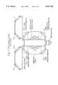
- FIG. 1shows the cross-section of an industrial four target PVD coater (detailed description: W.-D. Munz, D. Schulze, F. J. M. Hauzer, Surf. Coat. Technol., 50 (1992) 169).
- Four cathodesare mounted vertically into the doors of the vacuum chamber. The cathodes are of linear design.
- targetswith a typical dimension of 60 cm ⁇ 20 cm (target thickness: 1-2 cm) are mounted on the four cathodes.
- the substrates to be coatedare mounted on a rotating turntable as shown in FIG. 1. They are subjected to a three-fold planetary rotation as outlined by the arrows in FIG. 1. During coating they are passing all four cathodes collecting vaporized atoms sputtered from the cathodes. If a uniform distribution of an alloy material is required all four targets should be mounted with identical sputtering materials. In case of the TiAlYN deposition all four cathodes should be equipped with targets of the same composition.
- the yttriumis unevenly distributed over the entire hard material layer thickness and this special distribution can be obtained in a multi-target deposition system in which the yttrium is not alloyed into all targets and preferably only into a single target.
- one cathodewas equipped with a Cr target.
- the Cr targetwas used to perform the metal-ion-etch process in a steered arc discharge to establish in vacuo a clean substrate surface.
- Crwas chosen as target material to reduce the generation of droplets which deposit on the substrate surface and cause growth defects there in the deposited TiAlN (W.-D. Munz, I. V. Smith, L. A. Donohue, V. S. Brooks, German Patent Application 195 47 305.1) or TiAlYN coating.
- Two targetsconsisted of 50 at % Ti and 50 at % Al.
- the Y-containing targetwith typically 48 at % Ti, 48 at Al and 4 at % Y was mounted between the two TiAl targets.
- FIG. 1describes the actual target assembly.
- a schematic process sequenceis outlined in FIG. 2. It can be seen there also that the deposition of the hard coating with the unbalanced magnetron starts initially without using the TiAlY target. It has been found that the deposition of a pure TiAlN base layer enhances the adhesion of a TiAlN based quaternary coating like TiAlNbN or as in the case described here with TiAlYN. It has also to be mentioned that the Cr cathode was used during the deposition of TiAlN and TiAlYN in the unbalanced magnetron mode on a very low power level.
- the Cr targetwas powered with 0.2 to 1 kW, typically with 0.5 kW. Initially, it was thought to prevent cross-contamination from the TiAl targets. However, it has been found out surprisingly that a low chromium content of the coating led to an increase of the oxidation resistance when compared to a pure TiAlN coating.
- Table 1A detailed set of coating parameters is given in Table 1.
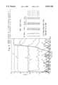
- FIGS. 3 to 5The stabilisation of the interface between the hard coating and a steel substrate by the uneven incorporation of Y is shown in FIGS. 3 to 5 using SNMS (Secondary Neutral Mass Spectroscopy) analyses.
- FIG. 3shows the completely uniform distribution of the coating constituents Al (4), Ti (6), Cr (7), N (3) over the complete thickness range.
- the intensity of the metal concentrationis given in non-calibrated counts.
- no Ywas incorporated. Therefore, Y is only identified as a low concentrated random element.
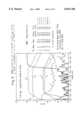
- the samplehas been heat treated for one hour in air at 800° C. Despite this heat treatment a sharp decay of the Fe signal (8) is observed at the interface indicating that no significant diffusion of Fe into the hard coating has taken place. Only a rather thin oxide layer is formed on top of the TiAlN coating as indicated by the sharp increase of the oxygen signal (1) and the parallel decrease of the N signal (3). However, if one increases the heat treatment temperature to 900° C.
- FIG. 4a significant diffusion of Fe (6) into the coating is observed (FIG. 4).
- the formation of a surface oxide layeris intensified. Concluding from the shape of signal 4 (Al), 5 (Ti), 1 (O) and 3 (N) an almost N-free oxide is formed with an Al rich top layer and a Ti rich oxide between the Al-oxide and the TiAlN film.
- the formation of this N-free sandwich oxide on top of a TiAlN coatinghas been confirmed by earlier work (D. McIntyre, J. E. Greene, G. Hakansson, J.-E. Sundgren, W.-D. Munz, J. Appl. Phy. 67 (1990) 1542). Extrapolation from the observed data (point "A" in FIG.
- SNMSshows only that the Al rich oxide is more or less Y-free and that there exists some indication that Y is incorporated into the Ti oxide portion. It can also be seen that the thickness of the sandwich oxide is reduced by the incorporation of Y to an approximate thickness of 0.65 ⁇ m.
- FIG. 6shows isotherms recorded at a temperature of 900° C. and over a reaction time in air up to 10 hours. It can be clearly seen that 2 at % Cr already reduce the weight gain due to oxidation during the reaction of TiAlN with hot air. However, the most pronounced improvement was found when Y was added in the "uneven" mode into the coating. For comparison reasons the oxidation behavior of TiN is given in FIG. 6 also.
- FIG. 7aexhibits an XRD diagram of a Ti 0 ,42 Al 9 ,58 N coating.
- the XRD diagram of TiAlN with continuous Y distributionis very similar although the peaks are somewhat broader, indicating higher internal stresses and smaller grain size of the polycrystalline coating.
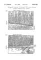
- FIGS. 8a and 8bshow computer processed TEM images which show in FIG. 8a the typical columnar growth of TiAlN coatings as reported in earlier work (G. Hakansson, J.-E. Sundgren, D. McIntyre, E. Greene, W.-D. Munz, Thin Solid Films, 153 (1987) 55).
- FIG. 8bhowever demonstrates a very fine grained film growth with clear indications of regular columnar growth only in the direct vicinity of the interface.
- the base layerwas deposited as outlined in FIG. 2.
- FIG. 8bsupports also the understanding of reduced oxidation of Y containing TiAlN coating due to the obviously prolonged diffusion paths for oxygen along the reduced grain sizes. It is also common knowledge that fine grained hard coatings are subjected to high internal stresses. The TEM results therefore justify the introduction of the Y-free base layer since via this graded interface the influence of the internal stresses onto the adhesion of the coatings should be reduced.
- the higher internal stresses of the fine grained TiAlYNmay be quantified also by an enhanced hardness HK 2700 in comparison to the Y-free coating with typically HK 2400.
- the hard material layershould itself be very smooth (W.-D. Munz, I. V. Smith, L. A. Donohue, J. S. Brooks, Patent Application 195 47 305.1) in order to bring about the advantageous influence of the yttrium.
Landscapes
- Chemical & Material Sciences (AREA)
- Chemical Kinetics & Catalysis (AREA)
- Engineering & Computer Science (AREA)
- Materials Engineering (AREA)
- Mechanical Engineering (AREA)
- Metallurgy (AREA)
- Organic Chemistry (AREA)
- Physical Vapour Deposition (AREA)
- Chemical Vapour Deposition (AREA)
- Cutting Tools, Boring Holders, And Turrets (AREA)
Abstract
Description
TABLE 1 ______________________________________ Important Process Parameters for a Four Cathode Combined Arc/ Unbalanced Magnetron PVD Coating Machine with a Typical Target Size of 60 cm × 20 cm Recommended Process Steps Units Parameter Range Conditions ______________________________________ Substrate Heat-up ° C. 250-550 450 Temperature Metal Ion Etch Target Material at % 100 Cr or 100 Cr at % 100 Mo Pressure Argon mbar 0-5.10.sup.-3 0.3-0.6 × 10.sup.-3 Current A 50-200 100 Substrate Bias V -1800 to -1500 -1200 Temperature ° C. 350-550 420-450 Duration min 1-20 10 Deposition Base Layer (UBM) Pressure total mbar 2-10 × 10.sup.-3 3.15 × 10.sup.-3 (Ar + N.sub.2) Pressure Ar mbar 1.5-9 × 10.sup.-3 3.25 × 10.sup.-2 Number UBM cathodes 2 2 Power per TiAl kW 6-12 8 cathode Power Cr Cathode kW 0-1.5 0.5 Bias voltage V -50 to -100 -75 Bias Current Density mA/cm.sup.2 2-5 3 Temperature ° C. 350-550 420-450 Thickness μm 0.1-2 0.2 Deposition of TiAlYN Pressure total (Ar + N.sub.2) mbar 2-10 × 10.sup.-3 3.5 × 10.sup.-3 Pressure Ar mbar 1.5-9 × 10.sup.-3 3.25 × 10.sup.-3 Power TiAl (2×) kW 6-12 6 Power TiAlY (1×) kW 6-12 6 Power Cr kW 0.2-1.5 0.5 Bias voltage V -50 to -100 -75 Bias Current Density mA/cm.sup.2 2-5 3 Tenperature ° C. 350-550 420-450 Thickness μm 2-6 3-5 Cooling down of ° C. 150-300 200+ Substrate Temperature ______________________________________
______________________________________ tool twist drills 8 mm diameter blind holes 27 mm in diatneter material machined GG25 (test iron) cutting speed 60 m/min feed 0.2 mm/revolution ______________________________________
______________________________________ drill uncoated 17 holes drill TiAlN (Ra = 0.15-0.20 μm) 100 holes drill TiAlN (Ra ≦ 0.05 μm) 250 holes drill TiAlYN (Ra ≦ 0.05 μm) 600-1,100 holes ______________________________________
Claims (30)
Applications Claiming Priority (3)
| Application Number | Priority Date | Filing Date | Title |
|---|---|---|---|
| DE19609647ADE19609647A1 (en) | 1996-03-12 | 1996-03-12 | Hard coating |
| DE19609647 | 1996-03-12 | ||
| PCT/EP1997/001234WO1997034023A1 (en) | 1996-03-12 | 1997-03-11 | Hard material coating with yttrium and method for its deposition |
Publications (1)
| Publication Number | Publication Date |
|---|---|
| US6033768Atrue US6033768A (en) | 2000-03-07 |
Family
ID=7788024
Family Applications (1)
| Application Number | Title | Priority Date | Filing Date |
|---|---|---|---|
| US08/945,871Expired - LifetimeUS6033768A (en) | 1996-03-12 | 1997-03-11 | Hard material coating with yttrium and method for its deposition |
Country Status (6)
| Country | Link |
|---|---|
| US (1) | US6033768A (en) |
| EP (1) | EP0833957B1 (en) |
| JP (1) | JP4482160B2 (en) |
| DE (2) | DE19609647A1 (en) |
| ES (1) | ES2154454T3 (en) |
| WO (1) | WO1997034023A1 (en) |
Cited By (49)
| Publication number | Priority date | Publication date | Assignee | Title |
|---|---|---|---|---|
| EP1219723A3 (en)* | 2000-12-28 | 2002-09-04 | Kabushiki Kaisha Kobe Seiko Sho | Hard film for cutting tools |
| EP1354984A2 (en) | 2002-03-20 | 2003-10-22 | Gühring, Jörg, Dr. | Wear resistant layer for chip cutting tools, specially rotating chip cutting tools, |
| US20040076856A1 (en)* | 2000-11-16 | 2004-04-22 | Hakan Hugosson | Surface coating of a carbide or a nitride |
| US6730392B2 (en)* | 2000-03-09 | 2004-05-04 | Metaplas Ionon Oberflächenveredelungstechnik GmbH | Hard layer coated parts |
| EP1431416A1 (en)* | 2002-12-10 | 2004-06-23 | Deutsches Zentrum für Luft- und Raumfahrt e.V. | Protective Ti-Al-Cr-N coating |
| US20040166378A1 (en)* | 2003-02-20 | 2004-08-26 | Ge Molly Mo Hui | Foodware with multilayer stick resistant ceramic coating and method of making |
| US20040256214A1 (en)* | 2001-02-12 | 2004-12-23 | Ingersoll-Rand Company | Process for forming decorative films and resulting products |
| US20050170091A1 (en)* | 2003-03-24 | 2005-08-04 | Ge Molly M.H. | Method of making foodware with a tarnish-resistant ceramic coating |
| WO2005123312A1 (en) | 2004-06-18 | 2005-12-29 | Mitsubishi Materials Corporation | Surface-coated cutware and process for producing the same |
| JP2006026883A (en)* | 2004-06-18 | 2006-02-02 | Mitsubishi Materials Corp | Surface-coated cemented carbide cutting tool exhibiting excellent wearing-resistance of hard coated layer in high speed cutting |
| US7033682B1 (en)* | 2001-12-28 | 2006-04-25 | Ues, Inc. | Coating solutions for titanium and titanium alloy machining |
| US20060099455A1 (en)* | 2004-11-09 | 2006-05-11 | Christoph Leyens | Protective Ti-AI-Cr-based nitrided coatings |
| JP2006150555A (en)* | 2004-12-01 | 2006-06-15 | Mitsubishi Materials Corp | Surface coated cemented carbide made cutting tool with hard coating layer displaying excellent abrasion resistance in high speed cutting of heat resisting alloy |
| JP2006150554A (en)* | 2004-12-01 | 2006-06-15 | Mitsubishi Materials Corp | Surface coated cemented carbide made cutting tool with hard coating layer displaying excellent abrasion resistance in high speed cutting of heat resisting alloy |
| US20060222891A1 (en)* | 2003-10-15 | 2006-10-05 | Weber Frank-R | Anti-abrasive layer |
| US20070000772A1 (en)* | 2005-03-24 | 2007-01-04 | Jurgen Ramm | Method for operating a pulsed arc source |
| EP1535680A4 (en)* | 2002-06-25 | 2007-11-07 | Mitsubishi Materials Corp | Coated cutting tool member |
| US20070259202A1 (en)* | 2004-10-22 | 2007-11-08 | Mitsubishi Materials Corporation | Surface-Coated Cutting Tool and Method for Producing Same |
| US20070264564A1 (en)* | 2006-03-16 | 2007-11-15 | Infinite Power Solutions, Inc. | Thin film battery on an integrated circuit or circuit board and method thereof |
| US20090162755A1 (en)* | 2007-12-21 | 2009-06-25 | Neudecker Bernd J | Thin Film Electrolyte for Thin Film Batteries |
| US20090181303A1 (en)* | 2008-01-11 | 2009-07-16 | Neudecker Bernd J | Thin Film Encapsulation for Thin Film Batteries and Other Devices |
| US20090307895A1 (en)* | 2002-08-09 | 2009-12-17 | Snyder Shawn W | Electrochemical Apparatus With Barrier Layer Protected Substrate |
| US20100032001A1 (en)* | 2008-08-11 | 2010-02-11 | Brantner Paul C | Energy Device With Integral Collector Surface For Electromagnetic Energy Harvesting And Method Thereof |
| US20100090477A1 (en)* | 2008-10-08 | 2010-04-15 | Keating Joseph A | Foot-Powered Footwear-Embedded Sensor-Transceiver |
| US20100203377A1 (en)* | 2002-08-09 | 2010-08-12 | Infinite Power Solutions | Metal Film Encapsulation |
| US20100255340A1 (en)* | 2009-04-07 | 2010-10-07 | National Material L.P. | Plain copper foodware and metal articles with durable and tarnish free multiplayer ceramic coating and method of making |
| US20110058912A1 (en)* | 2008-03-07 | 2011-03-10 | Seco Tools Ab | THERMALLY STABILIZED (Ti,Si)N LAYER FOR CUTTING TOOL INSERT |
| US20120052323A1 (en)* | 2010-08-26 | 2012-03-01 | Hon Hai Precision Industry Co., Ltd. | Process for surface treating aluminum or aluminum alloy and article made with same |
| US8197781B2 (en) | 2006-11-07 | 2012-06-12 | Infinite Power Solutions, Inc. | Sputtering target of Li3PO4 and method for producing same |
| US20120164477A1 (en)* | 2010-12-27 | 2012-06-28 | Hon Hai Precision Industry Co., Ltd. | Coated article and method for making same |
| US8236443B2 (en) | 2002-08-09 | 2012-08-07 | Infinite Power Solutions, Inc. | Metal film encapsulation |
| US8260203B2 (en) | 2008-09-12 | 2012-09-04 | Infinite Power Solutions, Inc. | Energy device with integral conductive surface for data communication via electromagnetic energy and method thereof |
| EP2540858A1 (en)* | 2011-06-30 | 2013-01-02 | Sandvik Intellectual Property AB | Cathodic arc deposition |
| US8350519B2 (en) | 2008-04-02 | 2013-01-08 | Infinite Power Solutions, Inc | Passive over/under voltage control and protection for energy storage devices associated with energy harvesting |
| DE102012013161A1 (en) | 2011-07-08 | 2013-01-10 | Kennametal Inc. | A coated article having yttrium-containing coatings deposited by physical vapor deposition and methods of making the same |
| US8394522B2 (en) | 2002-08-09 | 2013-03-12 | Infinite Power Solutions, Inc. | Robust metal film encapsulation |
| US8431264B2 (en) | 2002-08-09 | 2013-04-30 | Infinite Power Solutions, Inc. | Hybrid thin-film battery |
| US8445130B2 (en) | 2002-08-09 | 2013-05-21 | Infinite Power Solutions, Inc. | Hybrid thin-film battery |
| US20130134036A1 (en)* | 2011-11-29 | 2013-05-30 | Chenming Mold Ind. Corp. | Equipment for Making IC Shielding Coating Layer and Metal Shielding Layer of IC |
| US8508193B2 (en) | 2008-10-08 | 2013-08-13 | Infinite Power Solutions, Inc. | Environmentally-powered wireless sensor module |
| US8599572B2 (en) | 2009-09-01 | 2013-12-03 | Infinite Power Solutions, Inc. | Printed circuit board with integrated thin film battery |
| US20140353923A1 (en)* | 2012-01-12 | 2014-12-04 | Federal-Mogul Burscheid Gmbh | Piston ring |
| DE102014103220A1 (en)* | 2014-03-11 | 2015-09-17 | Walter Ag | TiAIN layers with lamellar structure |
| US20150336851A1 (en)* | 2012-12-21 | 2015-11-26 | Kabushiki Kaisha Kobe Seiko Sho (Kobe Steel, Ltd.) | Hard coating having excellent adhesion resistance to soft metal |
| US9334557B2 (en)* | 2007-12-21 | 2016-05-10 | Sapurast Research Llc | Method for sputter targets for electrolyte films |
| CN111155063A (en)* | 2019-12-31 | 2020-05-15 | 广州市尤特新材料有限公司 | Titanium-aluminum alloy target material and preparation method thereof |
| US10680277B2 (en) | 2010-06-07 | 2020-06-09 | Sapurast Research Llc | Rechargeable, high-density electrochemical device |
| US11306387B2 (en)* | 2020-01-17 | 2022-04-19 | Lockheed Martin Corporation | Thermal protection system for lightweight hypersonic missile fin |
| US20240345007A1 (en)* | 2023-04-27 | 2024-10-17 | Zhejiang University | Method for detecting internal stress distribution of transparent material based on x-ray diffraction (xrd) |
Families Citing this family (8)
| Publication number | Priority date | Publication date | Assignee | Title |
|---|---|---|---|---|
| JP3910373B2 (en) | 2001-03-13 | 2007-04-25 | オーエスジー株式会社 | Hard multilayer coating for rotary cutting tool and hard multilayer coating coated rotary cutting tool |
| EP1470880B1 (en)* | 2002-01-31 | 2015-08-12 | Mitsubishi Materials Corporation | Coated cutting tool member having hard coating layer and method for forming the hard coating layer on cutting tool |
| JP5443403B2 (en)* | 2004-09-30 | 2014-03-19 | 株式会社神戸製鋼所 | Hard coating excellent in high temperature lubricity and wear resistance and target for forming the hard coating |
| JP4668214B2 (en) | 2007-01-17 | 2011-04-13 | 株式会社神戸製鋼所 | Mold for molding |
| DE102008013964A1 (en)* | 2008-03-12 | 2009-09-17 | Kennametal Inc. | Hard material coated body |
| RU2485210C2 (en)* | 2011-08-16 | 2013-06-20 | Федеральное государственное автономное образовательное учреждение высшего профессионального образования "Национальный исследовательский технологический университет "МИСиС" | Method for hybrid obtaining of wear-resistant coating on cutting tool |
| KR101640912B1 (en) | 2014-07-03 | 2016-07-20 | 현대자동차주식회사 | High temperature low friction coating layer and the method of the same |
| CN110195212A (en)* | 2019-05-09 | 2019-09-03 | 厦门建霖健康家居股份有限公司 | A kind of method of arc ion plating |
Citations (7)
| Publication number | Priority date | Publication date | Assignee | Title |
|---|---|---|---|---|
| US4252862A (en)* | 1977-06-10 | 1981-02-24 | Nobuo Nishida | Externally ornamental golden colored part |
| US4761346A (en)* | 1984-11-19 | 1988-08-02 | Avco Corporation | Erosion-resistant coating system |
| US4871434A (en)* | 1986-04-05 | 1989-10-03 | Leybold-Heraeus Gmbh | Process for equipment to coat tools for machining and forming techniques with mechanically resistant layers |
| US5208102A (en)* | 1991-01-21 | 1993-05-04 | Balzers Aktiengesellschaft | Coated highly wear-resistant tool and physical coating process therefor |
| US5306407A (en)* | 1989-06-27 | 1994-04-26 | Hauzer Holding Bv | Method and apparatus for coating substrates |
| US5330853A (en)* | 1991-03-16 | 1994-07-19 | Leybold Ag | Multilayer Ti-Al-N coating for tools |
| US5549975A (en)* | 1993-07-29 | 1996-08-27 | Balzers Aktiengesellschaft | Coated tool and cutting process |
Family Cites Families (2)
| Publication number | Priority date | Publication date | Assignee | Title |
|---|---|---|---|---|
| JPS6051550B2 (en)* | 1981-10-30 | 1985-11-14 | 株式会社井上ジャパックス研究所 | Surface coating method |
| DE4405477A1 (en)* | 1994-02-21 | 1995-08-24 | Hauzer Holding | PVD process for the deposition of multi-component hard material layers |
- 1996
- 1996-03-12DEDE19609647Apatent/DE19609647A1/ennot_activeWithdrawn
- 1997
- 1997-03-11ESES97908214Tpatent/ES2154454T3/ennot_activeExpired - Lifetime
- 1997-03-11DEDE69704097Tpatent/DE69704097T2/ennot_activeExpired - Lifetime
- 1997-03-11USUS08/945,871patent/US6033768A/ennot_activeExpired - Lifetime
- 1997-03-11WOPCT/EP1997/001234patent/WO1997034023A1/enactiveIP Right Grant
- 1997-03-11EPEP97908214Apatent/EP0833957B1/ennot_activeExpired - Lifetime
- 1997-03-11JPJP53227997Apatent/JP4482160B2/ennot_activeExpired - Lifetime
Patent Citations (7)
| Publication number | Priority date | Publication date | Assignee | Title |
|---|---|---|---|---|
| US4252862A (en)* | 1977-06-10 | 1981-02-24 | Nobuo Nishida | Externally ornamental golden colored part |
| US4761346A (en)* | 1984-11-19 | 1988-08-02 | Avco Corporation | Erosion-resistant coating system |
| US4871434A (en)* | 1986-04-05 | 1989-10-03 | Leybold-Heraeus Gmbh | Process for equipment to coat tools for machining and forming techniques with mechanically resistant layers |
| US5306407A (en)* | 1989-06-27 | 1994-04-26 | Hauzer Holding Bv | Method and apparatus for coating substrates |
| US5208102A (en)* | 1991-01-21 | 1993-05-04 | Balzers Aktiengesellschaft | Coated highly wear-resistant tool and physical coating process therefor |
| US5330853A (en)* | 1991-03-16 | 1994-07-19 | Leybold Ag | Multilayer Ti-Al-N coating for tools |
| US5549975A (en)* | 1993-07-29 | 1996-08-27 | Balzers Aktiengesellschaft | Coated tool and cutting process |
Cited By (90)
| Publication number | Priority date | Publication date | Assignee | Title |
|---|---|---|---|---|
| US6730392B2 (en)* | 2000-03-09 | 2004-05-04 | Metaplas Ionon Oberflächenveredelungstechnik GmbH | Hard layer coated parts |
| US20040076856A1 (en)* | 2000-11-16 | 2004-04-22 | Hakan Hugosson | Surface coating of a carbide or a nitride |
| US6887562B2 (en)* | 2000-11-16 | 2005-05-03 | Hugosson H{Dot Over (Akan | Surface coating of a carbide or a nitride |
| US6824601B2 (en) | 2000-12-28 | 2004-11-30 | Kobe Steel, Ltd. | Hard film for cutting tools, cutting tool coated with hard film, process for forming hard film, and target used to form hard film |
| EP1702997A3 (en)* | 2000-12-28 | 2006-11-29 | Kabushiki Kaisha Kobe Seiko Sho | Hard film for cutting tools |
| US7186324B2 (en) | 2000-12-28 | 2007-03-06 | Kabushiki Kaisha Kobe Seiko Sho | Hard film cutting tools, cutting tool coated with hard film, process for forming hard film and target used to form hard film |
| EP1219723A3 (en)* | 2000-12-28 | 2002-09-04 | Kabushiki Kaisha Kobe Seiko Sho | Hard film for cutting tools |
| US20050186448A1 (en)* | 2000-12-28 | 2005-08-25 | Kabushiki Kaisha Kobe Seiko Sho (Kobe Steel, Ltd.) | Hard film for cutting tools, cutting tool coated with hard film, process for forming hard film and target used to form hard film |
| US6919288B2 (en) | 2000-12-28 | 2005-07-19 | Kobe Steel, Ltd. | Hard film for cutting tools, cutting tool coated with hard film, process for forming hard film, and target used to form hard film |
| US20040237840A1 (en)* | 2000-12-28 | 2004-12-02 | Kabushiki Kaisha Kobe Seiko Sho (Kobe Steel, Ltd.) | Hard film for cutting tools, cutting tool coated with hard film, process for forming hard film, and target used to form hard film |
| US20040256214A1 (en)* | 2001-02-12 | 2004-12-23 | Ingersoll-Rand Company | Process for forming decorative films and resulting products |
| US7033682B1 (en)* | 2001-12-28 | 2006-04-25 | Ues, Inc. | Coating solutions for titanium and titanium alloy machining |
| EP1354984A2 (en) | 2002-03-20 | 2003-10-22 | Gühring, Jörg, Dr. | Wear resistant layer for chip cutting tools, specially rotating chip cutting tools, |
| US20040005981A1 (en)* | 2002-03-20 | 2004-01-08 | Dr.Jorg Guhring | Wear-resistant coating for metal-removing tools, particularly for rotary metal-cutting tools |
| US7217466B2 (en) | 2002-03-20 | 2007-05-15 | Joerg Guehring | Wear-resistant coating for metal-removing tools, particularly for rotary metal-cutting tools |
| EP1354984A3 (en)* | 2002-03-20 | 2004-09-01 | Gühring, Jörg, Dr. | Wear resistant layer for chip cutting tools, specially rotating chip cutting tools, |
| EP1535680A4 (en)* | 2002-06-25 | 2007-11-07 | Mitsubishi Materials Corp | Coated cutting tool member |
| US8431264B2 (en) | 2002-08-09 | 2013-04-30 | Infinite Power Solutions, Inc. | Hybrid thin-film battery |
| US9634296B2 (en) | 2002-08-09 | 2017-04-25 | Sapurast Research Llc | Thin film battery on an integrated circuit or circuit board and method thereof |
| US8394522B2 (en) | 2002-08-09 | 2013-03-12 | Infinite Power Solutions, Inc. | Robust metal film encapsulation |
| US8236443B2 (en) | 2002-08-09 | 2012-08-07 | Infinite Power Solutions, Inc. | Metal film encapsulation |
| US9793523B2 (en) | 2002-08-09 | 2017-10-17 | Sapurast Research Llc | Electrochemical apparatus with barrier layer protected substrate |
| US8404376B2 (en) | 2002-08-09 | 2013-03-26 | Infinite Power Solutions, Inc. | Metal film encapsulation |
| US20100203377A1 (en)* | 2002-08-09 | 2010-08-12 | Infinite Power Solutions | Metal Film Encapsulation |
| US8445130B2 (en) | 2002-08-09 | 2013-05-21 | Infinite Power Solutions, Inc. | Hybrid thin-film battery |
| US20090307895A1 (en)* | 2002-08-09 | 2009-12-17 | Snyder Shawn W | Electrochemical Apparatus With Barrier Layer Protected Substrate |
| US8535396B2 (en) | 2002-08-09 | 2013-09-17 | Infinite Power Solutions, Inc. | Electrochemical apparatus with barrier layer protected substrate |
| EP1431416A1 (en)* | 2002-12-10 | 2004-06-23 | Deutsches Zentrum für Luft- und Raumfahrt e.V. | Protective Ti-Al-Cr-N coating |
| US20050186343A1 (en)* | 2003-02-20 | 2005-08-25 | Ge Molly M.H. | Method of making a stick resistant multi-layer ceramic coating |
| US6906295B2 (en)* | 2003-02-20 | 2005-06-14 | National Material L.P. | Foodware with multilayer stick resistant ceramic coating and method of making |
| US20040166378A1 (en)* | 2003-02-20 | 2004-08-26 | Ge Molly Mo Hui | Foodware with multilayer stick resistant ceramic coating and method of making |
| US7462375B2 (en) | 2003-02-20 | 2008-12-09 | National Material L.P. | Method of making a stick resistant multi-layer ceramic coating |
| US20050170091A1 (en)* | 2003-03-24 | 2005-08-04 | Ge Molly M.H. | Method of making foodware with a tarnish-resistant ceramic coating |
| US20060222891A1 (en)* | 2003-10-15 | 2006-10-05 | Weber Frank-R | Anti-abrasive layer |
| US7541101B2 (en)* | 2003-10-15 | 2009-06-02 | Joerg Guehring | Anti-abrasive layer |
| EP1757388A4 (en)* | 2004-06-18 | 2008-09-03 | Mitsubishi Materials Corp | SURFACE-COATED CUTTING TOOL AND METHOD OF MANUFACTURING THE SAME |
| WO2005123312A1 (en) | 2004-06-18 | 2005-12-29 | Mitsubishi Materials Corporation | Surface-coated cutware and process for producing the same |
| JP2006026883A (en)* | 2004-06-18 | 2006-02-02 | Mitsubishi Materials Corp | Surface-coated cemented carbide cutting tool exhibiting excellent wearing-resistance of hard coated layer in high speed cutting |
| US7799438B2 (en) | 2004-06-18 | 2010-09-21 | Mitsubishi Materials Corporation | Surface-coated cutting tool and method for producing same |
| US20070259202A1 (en)* | 2004-10-22 | 2007-11-08 | Mitsubishi Materials Corporation | Surface-Coated Cutting Tool and Method for Producing Same |
| US7160635B2 (en) | 2004-11-09 | 2007-01-09 | Sheffield Hallam University | Protective Ti-Al-Cr-based nitrided coatings |
| US20060099455A1 (en)* | 2004-11-09 | 2006-05-11 | Christoph Leyens | Protective Ti-AI-Cr-based nitrided coatings |
| JP2006150554A (en)* | 2004-12-01 | 2006-06-15 | Mitsubishi Materials Corp | Surface coated cemented carbide made cutting tool with hard coating layer displaying excellent abrasion resistance in high speed cutting of heat resisting alloy |
| JP2006150555A (en)* | 2004-12-01 | 2006-06-15 | Mitsubishi Materials Corp | Surface coated cemented carbide made cutting tool with hard coating layer displaying excellent abrasion resistance in high speed cutting of heat resisting alloy |
| US20070000772A1 (en)* | 2005-03-24 | 2007-01-04 | Jurgen Ramm | Method for operating a pulsed arc source |
| CN104201082A (en)* | 2005-03-24 | 2014-12-10 | 奥尔利康贸易股份公司(特吕巴赫) | Method for operating a pulsed arc source |
| US9997338B2 (en)* | 2005-03-24 | 2018-06-12 | Oerlikon Surface Solutions Ag, Pfäffikon | Method for operating a pulsed arc source |
| US20070264564A1 (en)* | 2006-03-16 | 2007-11-15 | Infinite Power Solutions, Inc. | Thin film battery on an integrated circuit or circuit board and method thereof |
| US8197781B2 (en) | 2006-11-07 | 2012-06-12 | Infinite Power Solutions, Inc. | Sputtering target of Li3PO4 and method for producing same |
| US8268488B2 (en) | 2007-12-21 | 2012-09-18 | Infinite Power Solutions, Inc. | Thin film electrolyte for thin film batteries |
| US9334557B2 (en)* | 2007-12-21 | 2016-05-10 | Sapurast Research Llc | Method for sputter targets for electrolyte films |
| US20090162755A1 (en)* | 2007-12-21 | 2009-06-25 | Neudecker Bernd J | Thin Film Electrolyte for Thin Film Batteries |
| US9786873B2 (en) | 2008-01-11 | 2017-10-10 | Sapurast Research Llc | Thin film encapsulation for thin film batteries and other devices |
| US8518581B2 (en) | 2008-01-11 | 2013-08-27 | Inifinite Power Solutions, Inc. | Thin film encapsulation for thin film batteries and other devices |
| US20090181303A1 (en)* | 2008-01-11 | 2009-07-16 | Neudecker Bernd J | Thin Film Encapsulation for Thin Film Batteries and Other Devices |
| US8389115B2 (en) | 2008-03-07 | 2013-03-05 | Seco Tools Ab | Thermally stabilized (Ti,Si)N layer for cutting tool insert |
| US20110058912A1 (en)* | 2008-03-07 | 2011-03-10 | Seco Tools Ab | THERMALLY STABILIZED (Ti,Si)N LAYER FOR CUTTING TOOL INSERT |
| US8350519B2 (en) | 2008-04-02 | 2013-01-08 | Infinite Power Solutions, Inc | Passive over/under voltage control and protection for energy storage devices associated with energy harvesting |
| US20100032001A1 (en)* | 2008-08-11 | 2010-02-11 | Brantner Paul C | Energy Device With Integral Collector Surface For Electromagnetic Energy Harvesting And Method Thereof |
| US8906523B2 (en) | 2008-08-11 | 2014-12-09 | Infinite Power Solutions, Inc. | Energy device with integral collector surface for electromagnetic energy harvesting and method thereof |
| US8260203B2 (en) | 2008-09-12 | 2012-09-04 | Infinite Power Solutions, Inc. | Energy device with integral conductive surface for data communication via electromagnetic energy and method thereof |
| US8508193B2 (en) | 2008-10-08 | 2013-08-13 | Infinite Power Solutions, Inc. | Environmentally-powered wireless sensor module |
| US20100090477A1 (en)* | 2008-10-08 | 2010-04-15 | Keating Joseph A | Foot-Powered Footwear-Embedded Sensor-Transceiver |
| US8021768B2 (en) | 2009-04-07 | 2011-09-20 | National Material, L.P. | Plain copper foodware and metal articles with durable and tarnish free multiplayer ceramic coating and method of making |
| US20100255340A1 (en)* | 2009-04-07 | 2010-10-07 | National Material L.P. | Plain copper foodware and metal articles with durable and tarnish free multiplayer ceramic coating and method of making |
| US9532453B2 (en) | 2009-09-01 | 2016-12-27 | Sapurast Research Llc | Printed circuit board with integrated thin film battery |
| US8599572B2 (en) | 2009-09-01 | 2013-12-03 | Infinite Power Solutions, Inc. | Printed circuit board with integrated thin film battery |
| US10680277B2 (en) | 2010-06-07 | 2020-06-09 | Sapurast Research Llc | Rechargeable, high-density electrochemical device |
| US20120052323A1 (en)* | 2010-08-26 | 2012-03-01 | Hon Hai Precision Industry Co., Ltd. | Process for surface treating aluminum or aluminum alloy and article made with same |
| US20120164477A1 (en)* | 2010-12-27 | 2012-06-28 | Hon Hai Precision Industry Co., Ltd. | Coated article and method for making same |
| US9587305B2 (en) | 2011-06-30 | 2017-03-07 | Lamina Technologies S.A. | Cathodic arc deposition |
| EP2540858A1 (en)* | 2011-06-30 | 2013-01-02 | Sandvik Intellectual Property AB | Cathodic arc deposition |
| CN103732785A (en)* | 2011-06-30 | 2014-04-16 | 拉米娜科技 | Cathodic arc deposition |
| CN103732785B (en)* | 2011-06-30 | 2016-03-16 | 拉米娜科技 | Cathodic arc deposition |
| WO2013000990A1 (en)* | 2011-06-30 | 2013-01-03 | Sandvik Intellectual Property Ab | Cathodic arc deposition |
| GB2492885A (en)* | 2011-07-08 | 2013-01-16 | Kennametal Inc | Yttrium-containing coating applied by PVD |
| DE102012013161B4 (en) | 2011-07-08 | 2019-07-11 | Kennametal Inc. | A coated article having yttrium-containing coatings deposited by physical vapor deposition and methods of making the same |
| DE102012013161A1 (en) | 2011-07-08 | 2013-01-10 | Kennametal Inc. | A coated article having yttrium-containing coatings deposited by physical vapor deposition and methods of making the same |
| US8475943B2 (en) | 2011-07-08 | 2013-07-02 | Kennametal Inc. | Coated article having yttrium-containing coatings applied by physical vapor deposition and method for making the same |
| US20130134036A1 (en)* | 2011-11-29 | 2013-05-30 | Chenming Mold Ind. Corp. | Equipment for Making IC Shielding Coating Layer and Metal Shielding Layer of IC |
| US20140353923A1 (en)* | 2012-01-12 | 2014-12-04 | Federal-Mogul Burscheid Gmbh | Piston ring |
| US9915346B2 (en)* | 2012-01-12 | 2018-03-13 | Federal-Mogul Burscheid Gmbh | Piston ring |
| US9751809B2 (en)* | 2012-12-21 | 2017-09-05 | Kobe Steel, Ltd. | Hard coating having excellent adhesion resistance to soft metal |
| US20150336851A1 (en)* | 2012-12-21 | 2015-11-26 | Kabushiki Kaisha Kobe Seiko Sho (Kobe Steel, Ltd.) | Hard coating having excellent adhesion resistance to soft metal |
| DE102014103220A1 (en)* | 2014-03-11 | 2015-09-17 | Walter Ag | TiAIN layers with lamellar structure |
| US10214810B2 (en) | 2014-03-11 | 2019-02-26 | Walter Ag | TiAlCN layers with lamellar structure |
| CN111155063A (en)* | 2019-12-31 | 2020-05-15 | 广州市尤特新材料有限公司 | Titanium-aluminum alloy target material and preparation method thereof |
| US11306387B2 (en)* | 2020-01-17 | 2022-04-19 | Lockheed Martin Corporation | Thermal protection system for lightweight hypersonic missile fin |
| US20240345007A1 (en)* | 2023-04-27 | 2024-10-17 | Zhejiang University | Method for detecting internal stress distribution of transparent material based on x-ray diffraction (xrd) |
| US12203881B2 (en)* | 2023-04-27 | 2025-01-21 | Zhejiang University | Method of detecting internal stress distribution of transparent material based on x-ray diffraction |
Also Published As
| Publication number | Publication date |
|---|---|
| DE19609647A1 (en) | 1997-09-18 |
| DE69704097D1 (en) | 2001-03-29 |
| EP0833957B1 (en) | 2001-02-21 |
| WO1997034023A1 (en) | 1997-09-18 |
| DE69704097T2 (en) | 2001-07-19 |
| JP4482160B2 (en) | 2010-06-16 |
| ES2154454T3 (en) | 2001-04-01 |
| JPH11505573A (en) | 1999-05-21 |
| EP0833957A1 (en) | 1998-04-08 |
Similar Documents
| Publication | Publication Date | Title |
|---|---|---|
| US6033768A (en) | Hard material coating with yttrium and method for its deposition | |
| RU2456371C2 (en) | Laminated system with layer of mixed crystals of multicomponent oxide | |
| Matthews | Titanium nitride PVD coating technology | |
| US7601440B2 (en) | Hard coating excellent in wear resistance and in oxidation resistance and target for forming the same | |
| US8173278B2 (en) | Coated body | |
| EP1174528B1 (en) | Multilayer-coated cutting tool | |
| US6919288B2 (en) | Hard film for cutting tools, cutting tool coated with hard film, process for forming hard film, and target used to form hard film | |
| JP4062583B2 (en) | Hard coating for cutting tool, method for producing the same, and target for forming hard coating | |
| US6767627B2 (en) | Hard film, wear-resistant object and method of manufacturing wear-resistant object | |
| EP2340321B1 (en) | Non gamma - phase cubic alcro | |
| CA2576946C (en) | Hard multilayer coating, and hard multilayer coated tool including the hard multilayer coating | |
| JP4427271B2 (en) | Alumina protective film and method for producing the same | |
| GB2075068A (en) | Articles coated with hard materials | |
| JP5261981B2 (en) | Coated cutting tool | |
| KR101170396B1 (en) | Hard coating and its production method | |
| JP5035979B2 (en) | Surface-coated cutting tool that exhibits high wear resistance with a hard coating layer in high-speed milling and a method for producing the same | |
| JPH11158606A (en) | Wear resistant coating | |
| JPH08333675A (en) | Article with oxidation-resistant / wear-resistant coating and method for producing the same |
Legal Events
| Date | Code | Title | Description |
|---|---|---|---|
| AS | Assignment | Owner name:HAUZER INDUSTRIES BV, NETHERLANDS Free format text:ASSIGNMENT OF ASSIGNORS INTEREST;ASSIGNORS:MUENZ, WOLF-DIETER;SMITH, IAN;DONOHUE, LEE ADRIAN;AND OTHERS;REEL/FRAME:008891/0541;SIGNING DATES FROM 19971013 TO 19971017 | |
| STCF | Information on status: patent grant | Free format text:PATENTED CASE | |
| AS | Assignment | Owner name:HAUZER TECHNO COATING EUROPE BV, NETHERLANDS Free format text:ASSIGNMENT OF ASSIGNORS INTEREST;ASSIGNOR:HAUZER INDUSTRIES BV;REEL/FRAME:012967/0822 Effective date:20020223 | |
| FEPP | Fee payment procedure | Free format text:PAYOR NUMBER ASSIGNED (ORIGINAL EVENT CODE: ASPN); ENTITY STATUS OF PATENT OWNER: LARGE ENTITY | |
| FPAY | Fee payment | Year of fee payment:4 | |
| FEPP | Fee payment procedure | Free format text:PAYER NUMBER DE-ASSIGNED (ORIGINAL EVENT CODE: RMPN); ENTITY STATUS OF PATENT OWNER: LARGE ENTITY Free format text:PAYOR NUMBER ASSIGNED (ORIGINAL EVENT CODE: ASPN); ENTITY STATUS OF PATENT OWNER: LARGE ENTITY | |
| FEPP | Fee payment procedure | Free format text:PAYER NUMBER DE-ASSIGNED (ORIGINAL EVENT CODE: RMPN); ENTITY STATUS OF PATENT OWNER: LARGE ENTITY Free format text:PAYOR NUMBER ASSIGNED (ORIGINAL EVENT CODE: ASPN); ENTITY STATUS OF PATENT OWNER: LARGE ENTITY | |
| FPAY | Fee payment | Year of fee payment:8 | |
| FPAY | Fee payment | Year of fee payment:12 | |
| AS | Assignment | Owner name:IHI HAUZER TECHNO COATING B.V., NETHERLANDS Free format text:CHANGE OF NAME;ASSIGNOR:HAUZER TECHNO COATING B.V.;REEL/FRAME:034501/0533 Effective date:20130527 Owner name:HAUZER TECHNO COATING B.V., NETHERLANDS Free format text:CHANGE OF NAME;ASSIGNOR:HAUZER TECHNO COATING EUROPE BV;REEL/FRAME:034501/0502 Effective date:20130523 |