US6031865A - Rapidly decorrelating spreading sequences for DS-CDMA transceivers - Google Patents
Rapidly decorrelating spreading sequences for DS-CDMA transceiversDownload PDFInfo
- Publication number
- US6031865A US6031865AUS08/905,376US90537697AUS6031865AUS 6031865 AUS6031865 AUS 6031865AUS 90537697 AUS90537697 AUS 90537697AUS 6031865 AUS6031865 AUS 6031865A
- Authority
- US
- United States
- Prior art keywords
- degrees
- phase
- signals
- angle
- spreading
- Prior art date
- Legal status (The legal status is an assumption and is not a legal conclusion. Google has not performed a legal analysis and makes no representation as to the accuracy of the status listed.)
- Expired - Lifetime
Links
- 230000007480spreadingEffects0.000titleclaimsabstractdescription35
- 238000004891communicationMethods0.000claimsabstractdescription10
- 238000000034methodMethods0.000claimsdescription13
- 230000010363phase shiftEffects0.000claimsdescription7
- 230000000694effectsEffects0.000claimsdescription4
- 238000001228spectrumMethods0.000claimsdescription4
- 230000005540biological transmissionEffects0.000claimsdescription3
- 230000004044responseEffects0.000description12
- 230000002452interceptive effectEffects0.000description9
- 239000013598vectorSubstances0.000description4
- 230000001427coherent effectEffects0.000description3
- 238000001514detection methodMethods0.000description3
- 230000006872improvementEffects0.000description3
- 238000012935AveragingMethods0.000description2
- 238000013459approachMethods0.000description2
- 230000001413cellular effectEffects0.000description2
- 230000003111delayed effectEffects0.000description2
- 238000010586diagramMethods0.000description2
- 238000007493shaping processMethods0.000description2
- 230000003595spectral effectEffects0.000description2
- 230000007704transitionEffects0.000description2
- XMQFTWRPUQYINF-UHFFFAOYSA-Nbensulfuron-methylChemical compoundCOC(=O)C1=CC=CC=C1CS(=O)(=O)NC(=O)NC1=NC(OC)=CC(OC)=N1XMQFTWRPUQYINF-UHFFFAOYSA-N0.000description1
- 230000008859changeEffects0.000description1
- 238000012937correctionMethods0.000description1
- 230000001186cumulative effectEffects0.000description1
- 230000007423decreaseEffects0.000description1
- 230000006698inductionEffects0.000description1
- 230000008569processEffects0.000description1
Images


Classifications
- H—ELECTRICITY
- H04—ELECTRIC COMMUNICATION TECHNIQUE
- H04L—TRANSMISSION OF DIGITAL INFORMATION, e.g. TELEGRAPHIC COMMUNICATION
- H04L27/00—Modulated-carrier systems
- H04L27/18—Phase-modulated carrier systems, i.e. using phase-shift keying
- H04L27/20—Modulator circuits; Transmitter circuits
- H04L27/2032—Modulator circuits; Transmitter circuits for discrete phase modulation, e.g. in which the phase of the carrier is modulated in a nominally instantaneous manner
- H04L27/2035—Modulator circuits; Transmitter circuits for discrete phase modulation, e.g. in which the phase of the carrier is modulated in a nominally instantaneous manner using a single or unspecified number of carriers
- H04L27/2042—Modulator circuits; Transmitter circuits for discrete phase modulation, e.g. in which the phase of the carrier is modulated in a nominally instantaneous manner using a single or unspecified number of carriers with more than two phase states
- H—ELECTRICITY
- H04—ELECTRIC COMMUNICATION TECHNIQUE
- H04B—TRANSMISSION
- H04B1/00—Details of transmission systems, not covered by a single one of groups H04B3/00 - H04B13/00; Details of transmission systems not characterised by the medium used for transmission
- H04B1/69—Spread spectrum techniques
- H04B1/707—Spread spectrum techniques using direct sequence modulation
Definitions
- the present inventionrelates generally to code division multiple access (CDMA) systems, and more particularly to a modulation scheme for gain spreading in a direct sequence CDMA (DS-CDMA) system.
- CDMAcode division multiple access
- DS-CDMAdirect sequence CDMA
- a CDMA systemincludes a system controller and at least one base station. Each base station provides communication service to a fixed geographic area or cell. Mobile stations in a cell communicate with the base station for that cell. Communication with a mobile station is handed off among base stations as the mobile station moves among cells.
- a CDMA systemincludes a system according to a EIA/TIA interim standard 95 Mobile Station-Base Station Compatibility Standard for Dual-Mode Wideband Spread Spectrum Cellular System ("IS-95").
- a typical DS-CDMA transmitter 100is shown in FIG. 1.
- the transmitteraccepts information bits. These may be digitized, compressed voice or digital data formatted in an appropriate protocol. These bits are encoded for error correction and interleaved in encoder and interleaver 101.
- the resulting binary data streamis mapped from binary data (0,1) to symbols (-1,+1) in the binary-to-numeric block 102.
- Each symbol of the emerging data streamis multiplied by a length N Walsh code, where N is normally an integer power of 2, by multiplier 103, in a process referred to as Walsh covering.
- the duration of each element of the Walsh codeis referred to as the chip duration and the inverse of this quantity is the chip rate.
- the sequence formed by the Walsh coveringis then multiplied by a complex spreading sequence. This is accomplished by performing two real multiplies, one in which the Walsh covered sequence is multiplied by a first psuedorandom noise sequence PNi by multiplier 104 to form the in-phase channel and the other by a second sequence PNq in multiplier 105 to form the quadrature component of the complex baseband signal.
- PNipsuedorandom noise sequence
- multiplier 104to form the in-phase channel
- PNq in multiplier 105to form the quadrature component of the complex baseband signal.
- the spreading sequence formed by PNi and occupy a quartenary phase shift keyed (QPSK) constellationand therefore will be referred to as a QPSK modulation or a QPSK spreading sequence.
- a spreading sequencewill be considered any sequence with relatively uniform spectrum over a desired range which is multiplied by a second sequence for the purpose uniformly distributing a signal across the extent of the desired band.
- the quadrature component of the complex baseband signalis delayed by 1/2 chip by delay element 106. Both the delayed quadrature and the in-phase component of the signal are then filtered by identical spectral shaping filters 107 and 108 to prevent out-of-band emissions.
- the filtered in-phase componentis then multiplied by cos( ⁇ t) in multiplier 113 and the filtered quadrature component by sin( ⁇ t) in multiplier 109 and the resulting signals summed in summer 110 to up-convert the baseband signal to the desired carrier frequency.
- the modulated carrier produced by summer 110is then amplified by power amplifier 111 to the desired power level.
- the peak magnitude of the output of the in-phase and/or quadrature signalswill exceed the average output magnitude.
- the ratio of the peak magnitude of the filter output to the average levelis referred to as peak-to-average ratio.
- High peak-to-average ratiosare undesirable because the power amplifier 111 must be linear over the entire signal range, including the peak value. Therefore the peak signal level determines both the size and bias requirements of the power amplifier. High peak-to-average ratios therefore imply higher current drain, large size, and more costly power amplifiers. These characteristics become very important in low cost, battery powered subscriber units.
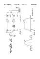
- FIG. 1is an overview of a DS-CDMA transmitter.
- FIG. 2is a typical impulse response and frequency response of the spectral shaping filters employed in a DS-CDMA system.
- FIG. 3is the constellation of a QPSK spreading sequence.
- FIG. 4is a representation of the vector addition of two vectors each with 4 possible values.
- FIG. 5is a block diagram of a ⁇ /2-BPSK modulator.
- FIG. 6is a representation of the possible phase shifts of the proposed spreading sequence.
- FIG. 7shows the vector addition of the chip components in a two chip duration filter system under the proposed invention.
- FIG. 8is a block diagram of the proposed spreading sequence.
- the present inventionprovides a spreading sequence for a communication system which is preferably a DS-CDMA system. Consecutive chips of signals transmitted in the communication system are shifted in phase for spread spectrum modulation.
- the phase shiftis plus or minus (+/-) 90 degrees plus or minus an angle phi having a value between 0 degrees and 45 degrees.
- phiis a function of the spreading function and is preferably pi/6.
- the modulation schemeis a QPSK modulation and the angle phi, in a second embodiment, is randomly selected.
- the spreading sequenceis preferably included in a transmitter in the telecommunication system.
- the peak signal level of a DS-CDMA transmittercan be determined by examination of the peak level of the complex output filters 107 and 108 in FIG. 1, in which the in-phase filter 107 output forms the real part and the quadrature filter 108 output is forms the imaginary part of the complex signal.
- this complex output signalis the convolution of the complex input signal, formed in a like manner to the output signal except for the use of the signals at the input to the filter, and the filter impulse response.
- a typical impulse response of these filtersis shown in FIG. 2. While this is a typical impulse response and not directly used by any known system, several properties of impulse response 201 are common to most DS-CDMA systems which attempt to minimize the bandwidth occupied by the transmitted signal.
- the vast majority of the energy of the filteris contained in the interval +/-Tc, and second the first zero crossings of the filter impulse response 201 occur near the points +/-Tc.
- the second conditionfollows because the minimum bandwidth which can be occupied by a DS-CDMA system is given by the chip rate, Rc.
- a typical frequency response 202is shown in FIG. 2. Given these two properties, much insight into the techniques affecting the peak signal level of the output complex signals can be investigated by assuming the impulse response of filters 107 and 108 are zero outside of the interval +/-Tc.
- the input complex signalsare constant over a chip duration Tc. Further, this signal can take on the values
- the output complex signalconsists of two components, one due to the present chip input and the one due to the previous chip input.
- the magnitude of the output complex signalwill be maximized when these two complex components add with the same phase.
- the magnitude of the resultantwill be twice the magnitude of signal due to each component.
- the components due to each of the two chipswill have equal magnitude and have either the same phase angle or differ in phase by 90, 180, or 270 degrees.
- FIG. 4This vector addition of the complex valued components is shown in FIG. 4 (400).
- the componentsare shown adding in phase yielding a magnitude of 2, in 402 and 403, the components are +/-90 degrees out of phase yielding a magnitude sqrt(2), and in 404 the components are 180 degrees out of phase yielding zero magnitude.
- the magnitude of the output complex signalwill either be 0, sqrt(2), or 2. Because the sqrt(2) term appears for two phase differences and all phase differences are equally probable, the average power level in the output complex signal is twice the average power level of each chip component and the peak power level is 4 times the power in each chip component. Therefore the peak-to-average ratio is 2 or 3 dB.
- the peak signal leveloccurs when two consecutive chips possess the same value. If this situation is not allowed, the peak-to-average ratio can be reduced.
- One modulation method which accomplishes thisis referred to as ⁇ /2 shifted binary phase shift keying ( ⁇ /2-BPSK).
- ⁇ /2-BPSKthe phase of the next chip is determined by changing the phase of the present chip by +/-90 degrees, with the phase selected randomly as shown in FIG. 5 (500).
- the II/2-BPSK system shown in FIG. 5generates the Walsh covered information identically to the system in FIG. 1.
- the spreading sequenceis now generated by multiplying j by a PN sequence generated by pseudorandomly selecting +/-1 in multiplier 502 and multiplying this value by the present value of the chip sequence stored in register 504 in multiplier 503.
- Register 403is clocked at the chip rate. This generates a sequence in which consecutive chips are either +/-90 degrees out of phase with each other.
- the output of register 504is multiplied with Walsh covered information bits via multiplier 501, which outputs an input into a complex filter 505.
- the complex filteroutputs a real value which is multiplied with cos( ⁇ t) via multiplier 506 and also an imaginary value which is multiplied with sin( ⁇ t) via multiplier 507.
- the outputs of multipliers 506 and 507are summed in a summer 508, whose output is then amplified by a power amplifier 509.
- the ⁇ /2-BPSK spreading sequencewill produce output complex chip components which are always either +/-90 degrees out of phase with each other. Therefore, the output complex signal have a constant amplitude sqrt(2) times larger than the value of each chip component.
- the peak-to-average ratiois therefore 1 or 0 dB, a 3 dB improvement over QPSK. For more realistic filters, the improvement is not as great but still substantial.
- the peak-to-average ratiois less than 4.9 dB and 3.0 dB 99% of the time for QPSK and ⁇ 2-BPSK respectfully.
- ⁇ 2-BPSKshows marked improvement in the peak-to-average ratio when compared to QPSK
- ⁇ 2-BPSKshows a carrier phase dependence on the level of interference. In a situation in which one dominate interferer exists, this situation is undesirable as it can lead to long periods of time in which the interference is higher than the average value by as much as 3 dB.
- the desired and interfering signalswill either be in phase or antiphase during chip period N+1 if ⁇ 2-BPSK modulation is employed. This is because both the desired and interfering signals will have changed phase by +/-90 degrees, causing the relative phase of the two to change by 0 or 180 degrees. Therefore, if the interference is at a maximum due to carrier phase at chip N, it will be at a maximum during chip N+1. By induction, the interference level will always be at a maximum. Note that in practice this situation will not persist indefinitely due to motion of the mobile units and drifting of reference oscillators. However, these changes are slow and the interference can remain strong for considerable periods.
- the relative phase the desired and interfering signalswill differ by 0, 90, 180, or 270 degrees at chip N+1.
- the interference energyis equally likely to be either 1 or 0, and will on average be 0.5. Therefore, the phase alignment on a given chip implies that the average value of interference will be seen on subsequent chips. Because the relative phase angles of the desired and interfering signals are a function of path length and therefore random, to see the average value of interference regardless of relative carrier phase angle is the most desirable result possible.
- the proposed inventionteaches a spreading modulation which restricts the phase transitions of the input complex signal to +/-(90+ ⁇ ) degrees, where ⁇ is a binary (+/-1) code operating at the chip rate and ⁇ is a fixed phase term having a value between 0 and 45 degrees. These transitions are shown in FIG. 6 (600).
- the spreading modulationis applied to the data bits after Walsh covering.
- One method to generate this modulationis shown in FIG. 7 (700).
- the period for interference levels to return to average given that phase alignment occurred on chip Nis a function of the conditional auto-correlation of the spreading sequence. As the auto-correlation given that phase alignment occurred on chip N becomes shorter, the time for interference levels to return to normal will become shorter as well.
- the proposed modulationdecreases the peak-to-average ratio by guaranteeing that consecutive chips cannot line up in phase.
- This modulationdoes not give orthogonal output chip components as with ⁇ /2-BPSK, but can come arbitrarily close with small ⁇ . Assume that the two chip components 701 and 702 are both unit magnitude. Then the maximum of the resultant will have a magnitude of
- the average energywill be the average of the square of the above two equations, or simply 2.
- the peak-to-average of the energyis therefore 1+sin( ⁇ ) for the simple two chip duration filter.
- the peak-to-average ratio givenis the value which is not exceeded 99% of the time.
- the decorrelation periodsare given in chip periods, Tc. This defines the minimum appropriate spreading gain as a sequence which decorrelates in less than a bit time. Decorrelation in less than a bit time is important because sequences which do not decorrelate in less than a bit can have significant variations in interference levels from one bit to the next which results in a higher bit error rate than would be observed in average interference levels are observed over all bits.
- the proposed spreading sequenceis for a DS-CDMA radio transmitter.
- the phase consecutive chips of the transmitted signalsare shifted plus or minus 90 degrees plus or minus an angle between 0 degrees and 45 degrees.
- the spreadingis accomplished by multiplying a sequence of modulated information bits by the spreading sequence.
- the angle of the shift of the spreading sequencemay bechosen in response to pairs of bits from pseudorandom number generators as shown in FIG. 8. This angle ⁇ may be set to any value. However, ⁇ may be varied as a function of spreading gain to allow the minimum peak-to-average ratio to be achieved while still keeping the conditional cross correlation of time shifted versions of this spreading sequences short relative to a bit time.
- ⁇ of 30 degreesgives a special case in which the constellation contains only 6 possible points, 4 of which will be used at any one time.
- information bitsare mapped to the desired modulation in block 801.
- the output of block 801are multiplied with length N Walsh codes in multiplier 803, which outputs an input into another multiplier 804.
- PN 1 and PN 2are mapped to produce various phase shifts.
- the output of block 802is multiplied with the output of a register 811 via multiplier 810 which is clocked with a chip clock.
- the output of multiplier 810is also utilized as input to register 811.
- the output of register 811is used as an input to multiplier 804, whose output is input into a complex filter 805.
- the complex filter 805outputs a real value which is filtered by filter 812 and multiplied with cos( ⁇ t) (not shown) via multiplier 806.
- the complex filter 805also outputs an imaginary value which is filtered by filter 813 and multiplied with sin( ⁇ t) (not shown) via multiplier 807.
- the outputs of multipliers 806 and 807are summed in a summer 808, whose output is then amplified by a power amplifier 809.
Landscapes
- Engineering & Computer Science (AREA)
- Computer Networks & Wireless Communication (AREA)
- Signal Processing (AREA)
- Digital Transmission Methods That Use Modulated Carrier Waves (AREA)
- Mobile Radio Communication Systems (AREA)
Abstract
Description
sqrt(1/2)*(+/-1+/-j)
sqrt(2*(1+sin(Φ)))
sqrt((2*(1-sin(Φ)))
______________________________________ Peak to Average Suitable Φ Ratio (dB) Spreading factors ______________________________________ /32 3.0 >=64 2/32 3.2 >=16 3/32 3.4 >=8 4/32 3.6 >=4 /4 (equivalent to /4 QPSK) 4.5 Any QPSK 4.9 Any O-QPSK 4.2 Any ______________________________________
Claims (12)
Priority Applications (5)
| Application Number | Priority Date | Filing Date | Title |
|---|---|---|---|
| US08/905,376US6031865A (en) | 1997-08-04 | 1997-08-04 | Rapidly decorrelating spreading sequences for DS-CDMA transceivers |
| EP98922487AEP1027779B1 (en) | 1997-08-04 | 1998-05-22 | Rapidly decorrelating spreading sequences for ds-cdma transceivers |
| JP2000505700AJP4183906B2 (en) | 1997-08-04 | 1998-05-22 | Non-correlated spreading sequence in DS-CDMA communication processing |
| PCT/US1998/010534WO1999007089A1 (en) | 1997-08-04 | 1998-05-22 | Rapidly decorrelating spreading sequences for ds-cdma transceivers |
| DE69831169TDE69831169T2 (en) | 1997-08-04 | 1998-05-22 | FAST DECORRORING OUTLINE SEQUENCES FOR DS-CDMA TRANSMITTER RECEIVERS |
Applications Claiming Priority (1)
| Application Number | Priority Date | Filing Date | Title |
|---|---|---|---|
| US08/905,376US6031865A (en) | 1997-08-04 | 1997-08-04 | Rapidly decorrelating spreading sequences for DS-CDMA transceivers |
Publications (1)
| Publication Number | Publication Date |
|---|---|
| US6031865Atrue US6031865A (en) | 2000-02-29 |
Family
ID=25420724
Family Applications (1)
| Application Number | Title | Priority Date | Filing Date |
|---|---|---|---|
| US08/905,376Expired - LifetimeUS6031865A (en) | 1997-08-04 | 1997-08-04 | Rapidly decorrelating spreading sequences for DS-CDMA transceivers |
Country Status (5)
| Country | Link |
|---|---|
| US (1) | US6031865A (en) |
| EP (1) | EP1027779B1 (en) |
| JP (1) | JP4183906B2 (en) |
| DE (1) | DE69831169T2 (en) |
| WO (1) | WO1999007089A1 (en) |
Cited By (17)
| Publication number | Priority date | Publication date | Assignee | Title |
|---|---|---|---|---|
| US20020009127A1 (en)* | 2000-03-23 | 2002-01-24 | Misra Raj Mani | Efficient spreader for spread spectrum communication systems |
| US6369633B1 (en)* | 1999-07-27 | 2002-04-09 | Nippon Telegraph And Telephone Corporation | Quadrature signal generation system |
| US6459742B1 (en)* | 1997-08-04 | 2002-10-01 | Eads Defence And Security Networks | Digital modulation process and modulator implementing the process |
| US20030012272A1 (en)* | 2001-07-16 | 2003-01-16 | Carlson Arthur J. | System and method for rapid generation of low par Q-mode signals |
| US6515961B1 (en)* | 1999-03-10 | 2003-02-04 | Qualcomm Incorporated | Decresting peaks in a CDMA signal |
| US20030139195A1 (en)* | 2000-05-05 | 2003-07-24 | Greenwich Technologies Associates | Method and apparatus for broadcasting with spatially diverse signals |
| US20040091060A1 (en)* | 2002-11-08 | 2004-05-13 | Becker James C. | Architecture for universal modulator |
| US6788728B1 (en)* | 1999-01-12 | 2004-09-07 | Sony Corporation | System and method for reducing peak-to-average ratio of the reverse link modulator in a CDMA phone system |
| US20040196178A1 (en)* | 2000-05-05 | 2004-10-07 | Elam Carl M. | Remote sensing using rayleigh signaling |
| US6823021B1 (en) | 2000-10-27 | 2004-11-23 | Greenwich Technologies Associates | Method and apparatus for space division multiple access receiver |
| US20040264551A1 (en)* | 2003-06-30 | 2004-12-30 | Eidson Donald Brian | Procedure for BPSK modulation with reduced envelope peaking |
| US6981010B1 (en) | 2000-08-02 | 2005-12-27 | Board Of Regents Of The University Of Nebraska | System and method for generating psuedo-noise sequences |
| US7031370B1 (en)* | 1999-03-01 | 2006-04-18 | Sharp Kabushika Kaisha | Spread-spectrum communication device |
| US20070116065A1 (en)* | 2005-11-18 | 2007-05-24 | Fujitsu Limited | Communication system, communication method, transmitter and receiver |
| US20080186088A1 (en)* | 2003-06-30 | 2008-08-07 | Conexant Systems, Inc. | Procedure for BPSK Demodulation corresponding to BPSK Modulation with Reduced Envelope Peaking |
| US7433418B1 (en)* | 2001-09-28 | 2008-10-07 | Arraycomm, Llc | Method and apparatus for efficient storage of training sequences for peak to average power constrained modulation formats |
| US20090257476A1 (en)* | 2008-04-14 | 2009-10-15 | Katsumi Watanabe | Transmission device, comunication system, transmission method and program |
Families Citing this family (16)
| Publication number | Priority date | Publication date | Assignee | Title |
|---|---|---|---|---|
| JP3407254B1 (en) | 2002-01-31 | 2003-05-19 | 富士通株式会社 | Data transmission system and data transmission control method |
| US8391249B2 (en) | 2003-02-18 | 2013-03-05 | Qualcomm Incorporated | Code division multiplexing commands on a code division multiplexed channel |
| US7660282B2 (en) | 2003-02-18 | 2010-02-09 | Qualcomm Incorporated | Congestion control in a wireless data network |
| US8023950B2 (en) | 2003-02-18 | 2011-09-20 | Qualcomm Incorporated | Systems and methods for using selectable frame durations in a wireless communication system |
| US20040160922A1 (en) | 2003-02-18 | 2004-08-19 | Sanjiv Nanda | Method and apparatus for controlling data rate of a reverse link in a communication system |
| US7155236B2 (en) | 2003-02-18 | 2006-12-26 | Qualcomm Incorporated | Scheduled and autonomous transmission and acknowledgement |
| US8081598B2 (en) | 2003-02-18 | 2011-12-20 | Qualcomm Incorporated | Outer-loop power control for wireless communication systems |
| US8150407B2 (en) | 2003-02-18 | 2012-04-03 | Qualcomm Incorporated | System and method for scheduling transmissions in a wireless communication system |
| US7215930B2 (en) | 2003-03-06 | 2007-05-08 | Qualcomm, Incorporated | Method and apparatus for providing uplink signal-to-noise ratio (SNR) estimation in a wireless communication |
| US8705588B2 (en)* | 2003-03-06 | 2014-04-22 | Qualcomm Incorporated | Systems and methods for using code space in spread-spectrum communications |
| US8477592B2 (en) | 2003-05-14 | 2013-07-02 | Qualcomm Incorporated | Interference and noise estimation in an OFDM system |
| US8489949B2 (en) | 2003-08-05 | 2013-07-16 | Qualcomm Incorporated | Combining grant, acknowledgement, and rate control commands |
| US9350489B2 (en) | 2008-11-17 | 2016-05-24 | Thomson Licensing | FEC frame header design for cable television signals |
| WO2010065100A2 (en)* | 2008-12-02 | 2010-06-10 | Thomson Licensing | Method and apparatus for transmitting and receiving fec frame headers |
| US8995533B2 (en) | 2008-12-10 | 2015-03-31 | Thomson Licensing | Method and apparatus for transmitting and receiving FEC frame headers with variable header modulation |
| JP5583243B2 (en)* | 2013-06-05 | 2014-09-03 | 三菱電機株式会社 | Transmitter |
Citations (15)
| Publication number | Priority date | Publication date | Assignee | Title |
|---|---|---|---|---|
| US4652838A (en)* | 1985-04-17 | 1987-03-24 | Rca Corporation | Phase randomization to reduce detectability of phase or frequency-modulated digital signals |
| US4841552A (en)* | 1988-04-04 | 1989-06-20 | Unisys Corporation | Digital phase shifter |
| US5309474A (en)* | 1990-06-25 | 1994-05-03 | Qualcomm Incorporated | System and method for generating signal waveforms in a CDMA cellular telephone system |
| US5544167A (en)* | 1993-08-13 | 1996-08-06 | Matra Communication | Transmission method for CDMA radiotelephone communications, and apparatuses for implementing such method |
| US5548613A (en)* | 1993-12-30 | 1996-08-20 | Nec Corporation | DS/CDMA receiver using moving-averaged pilot signals for weighting and phase rotation of orthogonal data symbol vectors |
| US5559828A (en)* | 1994-05-16 | 1996-09-24 | Armstrong; John T. | Transmitted reference spread spectrum communication using a single carrier with two mutually orthogonal modulated basis vectors |
| US5581575A (en)* | 1993-11-01 | 1996-12-03 | Qualcomm Incorporated | Method and apparatus for transmission of variable rate digital data |
| US5619524A (en)* | 1994-10-04 | 1997-04-08 | Motorola, Inc. | Method and apparatus for coherent communication reception in a spread-spectrum communication system |
| US5623485A (en)* | 1995-02-21 | 1997-04-22 | Lucent Technologies Inc. | Dual mode code division multiple access communication system and method |
| US5648982A (en)* | 1994-09-09 | 1997-07-15 | Omnipoint Corporation | Spread spectrum transmitter |
| US5659573A (en)* | 1994-10-04 | 1997-08-19 | Motorola, Inc. | Method and apparatus for coherent reception in a spread-spectrum receiver |
| US5734647A (en)* | 1994-12-12 | 1998-03-31 | Nec | CDMA communication system in which interference removing capability is improved |
| US5751705A (en)* | 1995-06-30 | 1998-05-12 | Nec Corporation | Code division multiple access base station transmitter |
| US5793798A (en)* | 1995-12-18 | 1998-08-11 | Ail Systems, Inc. | Virtual beam system |
| US5818867A (en)* | 1996-09-09 | 1998-10-06 | Itt Industries, Inc. | QPSK/QBL-MSK waveform enhancement |
- 1997
- 1997-08-04USUS08/905,376patent/US6031865A/ennot_activeExpired - Lifetime
- 1998
- 1998-05-22EPEP98922487Apatent/EP1027779B1/ennot_activeExpired - Lifetime
- 1998-05-22DEDE69831169Tpatent/DE69831169T2/ennot_activeExpired - Lifetime
- 1998-05-22JPJP2000505700Apatent/JP4183906B2/ennot_activeExpired - Fee Related
- 1998-05-22WOPCT/US1998/010534patent/WO1999007089A1/enactiveIP Right Grant
Patent Citations (15)
| Publication number | Priority date | Publication date | Assignee | Title |
|---|---|---|---|---|
| US4652838A (en)* | 1985-04-17 | 1987-03-24 | Rca Corporation | Phase randomization to reduce detectability of phase or frequency-modulated digital signals |
| US4841552A (en)* | 1988-04-04 | 1989-06-20 | Unisys Corporation | Digital phase shifter |
| US5309474A (en)* | 1990-06-25 | 1994-05-03 | Qualcomm Incorporated | System and method for generating signal waveforms in a CDMA cellular telephone system |
| US5544167A (en)* | 1993-08-13 | 1996-08-06 | Matra Communication | Transmission method for CDMA radiotelephone communications, and apparatuses for implementing such method |
| US5581575A (en)* | 1993-11-01 | 1996-12-03 | Qualcomm Incorporated | Method and apparatus for transmission of variable rate digital data |
| US5548613A (en)* | 1993-12-30 | 1996-08-20 | Nec Corporation | DS/CDMA receiver using moving-averaged pilot signals for weighting and phase rotation of orthogonal data symbol vectors |
| US5559828A (en)* | 1994-05-16 | 1996-09-24 | Armstrong; John T. | Transmitted reference spread spectrum communication using a single carrier with two mutually orthogonal modulated basis vectors |
| US5648982A (en)* | 1994-09-09 | 1997-07-15 | Omnipoint Corporation | Spread spectrum transmitter |
| US5619524A (en)* | 1994-10-04 | 1997-04-08 | Motorola, Inc. | Method and apparatus for coherent communication reception in a spread-spectrum communication system |
| US5659573A (en)* | 1994-10-04 | 1997-08-19 | Motorola, Inc. | Method and apparatus for coherent reception in a spread-spectrum receiver |
| US5734647A (en)* | 1994-12-12 | 1998-03-31 | Nec | CDMA communication system in which interference removing capability is improved |
| US5623485A (en)* | 1995-02-21 | 1997-04-22 | Lucent Technologies Inc. | Dual mode code division multiple access communication system and method |
| US5751705A (en)* | 1995-06-30 | 1998-05-12 | Nec Corporation | Code division multiple access base station transmitter |
| US5793798A (en)* | 1995-12-18 | 1998-08-11 | Ail Systems, Inc. | Virtual beam system |
| US5818867A (en)* | 1996-09-09 | 1998-10-06 | Itt Industries, Inc. | QPSK/QBL-MSK waveform enhancement |
Cited By (39)
| Publication number | Priority date | Publication date | Assignee | Title |
|---|---|---|---|---|
| US6459742B1 (en)* | 1997-08-04 | 2002-10-01 | Eads Defence And Security Networks | Digital modulation process and modulator implementing the process |
| US6788728B1 (en)* | 1999-01-12 | 2004-09-07 | Sony Corporation | System and method for reducing peak-to-average ratio of the reverse link modulator in a CDMA phone system |
| US7031370B1 (en)* | 1999-03-01 | 2006-04-18 | Sharp Kabushika Kaisha | Spread-spectrum communication device |
| US6515961B1 (en)* | 1999-03-10 | 2003-02-04 | Qualcomm Incorporated | Decresting peaks in a CDMA signal |
| US6369633B1 (en)* | 1999-07-27 | 2002-04-09 | Nippon Telegraph And Telephone Corporation | Quadrature signal generation system |
| US6885692B2 (en)* | 2000-03-23 | 2005-04-26 | Interdigital Technology Corporation | Efficient spreader for spread spectrum communication systems |
| US20070009013A1 (en)* | 2000-03-23 | 2007-01-11 | Interdigital Technology Corporation | Efficient spreader for spread spectrum communication systems |
| US7103088B2 (en) | 2000-03-23 | 2006-09-05 | Interdigital Technology Corporation | Efficient spreader for spread spectrum communication systems |
| US20020009127A1 (en)* | 2000-03-23 | 2002-01-24 | Misra Raj Mani | Efficient spreader for spread spectrum communication systems |
| US20050195885A1 (en)* | 2000-03-23 | 2005-09-08 | Interdigital Technology Corporation | Efficient spreader for spread spectrum communication systems |
| US20040092277A9 (en)* | 2000-05-05 | 2004-05-13 | Greenwich Technologies Associates | Method and apparatus for broadcasting with spatially diverse signals |
| US6833809B2 (en) | 2000-05-05 | 2004-12-21 | Greenwich Technologies Associates | Remote sensing using rayleigh signaling |
| US8767842B2 (en) | 2000-05-05 | 2014-07-01 | Greenwich Technologies Associates | Method and apparatus for broadcasting with spatially diverse signals |
| US7965794B2 (en) | 2000-05-05 | 2011-06-21 | Greenwich Technologies Associates | Method and apparatus for broadcasting with spatially diverse signals |
| US10547414B2 (en) | 2000-05-05 | 2020-01-28 | Greenwich Technologies Associates | Method and apparatus for broadcasting with spatially diverse signals |
| US20040196178A1 (en)* | 2000-05-05 | 2004-10-07 | Elam Carl M. | Remote sensing using rayleigh signaling |
| US20030139195A1 (en)* | 2000-05-05 | 2003-07-24 | Greenwich Technologies Associates | Method and apparatus for broadcasting with spatially diverse signals |
| US6981010B1 (en) | 2000-08-02 | 2005-12-27 | Board Of Regents Of The University Of Nebraska | System and method for generating psuedo-noise sequences |
| US8767796B2 (en) | 2000-10-27 | 2014-07-01 | Greenwich Technologies Associates | Method and apparatus for space division multiple access receiver |
| US7251286B2 (en) | 2000-10-27 | 2007-07-31 | Greenwich Technologies Associates | Method and apparatus for space division multiple access receiver |
| US20050265471A1 (en)* | 2000-10-27 | 2005-12-01 | Greenwich Technologies Associates | Method and apparatus for space division multiple access receiver |
| US20090323869A1 (en)* | 2000-10-27 | 2009-12-31 | Greenwich Technologies Associates | Method and apparatus for space division multiple access receiver |
| US6823021B1 (en) | 2000-10-27 | 2004-11-23 | Greenwich Technologies Associates | Method and apparatus for space division multiple access receiver |
| US7496129B2 (en) | 2000-10-27 | 2009-02-24 | Greenwich Technologies Associates | Method and apparatus for space division multiple access receiver |
| US7010028B2 (en)* | 2001-07-16 | 2006-03-07 | Broadcom Corporation | System and method for rapid generation of low par Q-mode signals |
| US20030012272A1 (en)* | 2001-07-16 | 2003-01-16 | Carlson Arthur J. | System and method for rapid generation of low par Q-mode signals |
| US7433418B1 (en)* | 2001-09-28 | 2008-10-07 | Arraycomm, Llc | Method and apparatus for efficient storage of training sequences for peak to average power constrained modulation formats |
| US7138882B2 (en)* | 2002-11-08 | 2006-11-21 | Northrop Grumman Corp | Architecture for universal modulator |
| US20040091060A1 (en)* | 2002-11-08 | 2004-05-13 | Becker James C. | Architecture for universal modulator |
| US20040264551A1 (en)* | 2003-06-30 | 2004-12-30 | Eidson Donald Brian | Procedure for BPSK modulation with reduced envelope peaking |
| US20080186088A1 (en)* | 2003-06-30 | 2008-08-07 | Conexant Systems, Inc. | Procedure for BPSK Demodulation corresponding to BPSK Modulation with Reduced Envelope Peaking |
| US7352797B2 (en) | 2003-06-30 | 2008-04-01 | Conexant Systems, Inc. | Procedure for BPSK modulation with reduced envelope peaking |
| US7729410B2 (en) | 2003-06-30 | 2010-06-01 | Nxp B.V. | Procedure for BPSK demodulation corresponding to BPSK modulation with reduced envelope peaking |
| WO2005006693A1 (en)* | 2003-06-30 | 2005-01-20 | Conexant Systems, Inc. | Bpsk modulation with reduced envelope peaks |
| US20070116065A1 (en)* | 2005-11-18 | 2007-05-24 | Fujitsu Limited | Communication system, communication method, transmitter and receiver |
| CN1968231B (en)* | 2005-11-18 | 2010-10-13 | 富士通株式会社 | Communication system, communication method, transmitter and receiver |
| US8451935B2 (en)* | 2008-04-14 | 2013-05-28 | Sony Corporation | Transmission device, communication system, transmission method and program |
| US8867654B2 (en) | 2008-04-14 | 2014-10-21 | Sony Corporation | Transmission device, communication system, transmission method and program |
| US20090257476A1 (en)* | 2008-04-14 | 2009-10-15 | Katsumi Watanabe | Transmission device, comunication system, transmission method and program |
Also Published As
| Publication number | Publication date |
|---|---|
| WO1999007089A1 (en) | 1999-02-11 |
| DE69831169D1 (en) | 2005-09-15 |
| EP1027779B1 (en) | 2005-08-10 |
| EP1027779A1 (en) | 2000-08-16 |
| JP4183906B2 (en) | 2008-11-19 |
| EP1027779A4 (en) | 2003-09-03 |
| JP2001512920A (en) | 2001-08-28 |
| DE69831169T2 (en) | 2006-02-02 |
Similar Documents
| Publication | Publication Date | Title |
|---|---|---|
| US6031865A (en) | Rapidly decorrelating spreading sequences for DS-CDMA transceivers | |
| JP3390771B2 (en) | Direct sequence band spreading code chip modulator | |
| EP0944182B1 (en) | Method and apparatus for adjusting transmission power of a CDMA terminal | |
| US6990138B2 (en) | Correlated spreading sequences for high rate non-coherent communication systems | |
| US9467200B2 (en) | Method and apparatus for orthogonally overlaying variable chip rate spread spectrum signals | |
| US6396868B1 (en) | Spread spectrum signal generating device and method in transmitter of mobile communications system | |
| US7031370B1 (en) | Spread-spectrum communication device | |
| EP0854586B1 (en) | Quadrature spread spectrum signal demodulation | |
| US7145863B2 (en) | Mobile station, base station, communication system, and communication method | |
| KR100938186B1 (en) | How to Retrieve Pilot Signals to Synchronize CDM Receivers and Associated Transmitters | |
| EP1205036A1 (en) | Signal generator and decoder | |
| JPH08251117A (en) | Multi-carrier transmission system and multi-carrier transmission method | |
| US6587452B1 (en) | High performance signal structure with multiple modulation formats | |
| EP1402633B1 (en) | Data transmission method and arrangement | |
| EP1708377B1 (en) | Reduced peak-to-average amplitude multichannel | |
| Yano et al. | Performance of DS/GMSK/PSK modem using four-phase correlator | |
| HK1099139B (en) | Reduced peak-to-average amplitude multichannel | |
| CA2620101A1 (en) | Quadriphase spreading codes in code division multiple access communications | |
| HK1144339A (en) | Reduced peak to average amplitude multichannel link |
Legal Events
| Date | Code | Title | Description |
|---|---|---|---|
| AS | Assignment | Owner name:MOTOROLA, INC., ILLINOIS Free format text:ASSIGNMENT OF ASSIGNORS INTEREST;ASSIGNORS:KELTON, JAMES ROBERT;WHINNETT, NICHOLAS WILLIAM;FRANK, COLIN D.;REEL/FRAME:009018/0121;SIGNING DATES FROM 19980107 TO 19980109 | |
| STCF | Information on status: patent grant | Free format text:PATENTED CASE | |
| CC | Certificate of correction | ||
| FPAY | Fee payment | Year of fee payment:4 | |
| FPAY | Fee payment | Year of fee payment:8 | |
| AS | Assignment | Owner name:MOTOROLA MOBILITY, INC, ILLINOIS Free format text:ASSIGNMENT OF ASSIGNORS INTEREST;ASSIGNOR:MOTOROLA, INC;REEL/FRAME:025673/0558 Effective date:20100731 | |
| FPAY | Fee payment | Year of fee payment:12 | |
| AS | Assignment | Owner name:MOTOROLA MOBILITY LLC, ILLINOIS Free format text:CHANGE OF NAME;ASSIGNOR:MOTOROLA MOBILITY, INC.;REEL/FRAME:029216/0282 Effective date:20120622 | |
| AS | Assignment | Owner name:GOOGLE TECHNOLOGY HOLDINGS LLC, CALIFORNIA Free format text:ASSIGNMENT OF ASSIGNORS INTEREST;ASSIGNOR:MOTOROLA MOBILITY LLC;REEL/FRAME:034305/0001 Effective date:20141028 |