US6030371A - Catheters and method for nonextrusion manufacturing of catheters - Google Patents
Catheters and method for nonextrusion manufacturing of cathetersDownload PDFInfo
- Publication number
- US6030371A US6030371AUS08/918,713US91871397AUS6030371AUS 6030371 AUS6030371 AUS 6030371AUS 91871397 AUS91871397 AUS 91871397AUS 6030371 AUS6030371 AUS 6030371A
- Authority
- US
- United States
- Prior art keywords
- polymer material
- layer
- catheter
- core
- medical tubing
- Prior art date
- Legal status (The legal status is an assumption and is not a legal conclusion. Google has not performed a legal analysis and makes no representation as to the accuracy of the status listed.)
- Expired - Lifetime
Links
Images


Classifications
- A—HUMAN NECESSITIES
- A61—MEDICAL OR VETERINARY SCIENCE; HYGIENE
- A61M—DEVICES FOR INTRODUCING MEDIA INTO, OR ONTO, THE BODY; DEVICES FOR TRANSDUCING BODY MEDIA OR FOR TAKING MEDIA FROM THE BODY; DEVICES FOR PRODUCING OR ENDING SLEEP OR STUPOR
- A61M25/00—Catheters; Hollow probes
- A61M25/0009—Making of catheters or other medical or surgical tubes
- A61M25/0012—Making of catheters or other medical or surgical tubes with embedded structures, e.g. coils, braids, meshes, strands or radiopaque coils
- A—HUMAN NECESSITIES
- A61—MEDICAL OR VETERINARY SCIENCE; HYGIENE
- A61M—DEVICES FOR INTRODUCING MEDIA INTO, OR ONTO, THE BODY; DEVICES FOR TRANSDUCING BODY MEDIA OR FOR TAKING MEDIA FROM THE BODY; DEVICES FOR PRODUCING OR ENDING SLEEP OR STUPOR
- A61M25/00—Catheters; Hollow probes
- A61M25/0009—Making of catheters or other medical or surgical tubes
- B—PERFORMING OPERATIONS; TRANSPORTING
- B05—SPRAYING OR ATOMISING IN GENERAL; APPLYING FLUENT MATERIALS TO SURFACES, IN GENERAL
- B05D—PROCESSES FOR APPLYING FLUENT MATERIALS TO SURFACES, IN GENERAL
- B05D1/00—Processes for applying liquids or other fluent materials
- B05D1/002—Processes for applying liquids or other fluent materials the substrate being rotated
- B—PERFORMING OPERATIONS; TRANSPORTING
- B05—SPRAYING OR ATOMISING IN GENERAL; APPLYING FLUENT MATERIALS TO SURFACES, IN GENERAL
- B05D—PROCESSES FOR APPLYING FLUENT MATERIALS TO SURFACES, IN GENERAL
- B05D1/00—Processes for applying liquids or other fluent materials
- B05D1/34—Applying different liquids or other fluent materials simultaneously
- B—PERFORMING OPERATIONS; TRANSPORTING
- B05—SPRAYING OR ATOMISING IN GENERAL; APPLYING FLUENT MATERIALS TO SURFACES, IN GENERAL
- B05D—PROCESSES FOR APPLYING FLUENT MATERIALS TO SURFACES, IN GENERAL
- B05D7/00—Processes, other than flocking, specially adapted for applying liquids or other fluent materials to particular surfaces or for applying particular liquids or other fluent materials
- B05D7/20—Processes, other than flocking, specially adapted for applying liquids or other fluent materials to particular surfaces or for applying particular liquids or other fluent materials to wires
- B—PERFORMING OPERATIONS; TRANSPORTING
- B23—MACHINE TOOLS; METAL-WORKING NOT OTHERWISE PROVIDED FOR
- B23K—SOLDERING OR UNSOLDERING; WELDING; CLADDING OR PLATING BY SOLDERING OR WELDING; CUTTING BY APPLYING HEAT LOCALLY, e.g. FLAME CUTTING; WORKING BY LASER BEAM
- B23K26/00—Working by laser beam, e.g. welding, cutting or boring
- B23K26/08—Devices involving relative movement between laser beam and workpiece
- B23K26/0823—Devices involving rotation of the workpiece
- B—PERFORMING OPERATIONS; TRANSPORTING
- B29—WORKING OF PLASTICS; WORKING OF SUBSTANCES IN A PLASTIC STATE IN GENERAL
- B29C—SHAPING OR JOINING OF PLASTICS; SHAPING OF MATERIAL IN A PLASTIC STATE, NOT OTHERWISE PROVIDED FOR; AFTER-TREATMENT OF THE SHAPED PRODUCTS, e.g. REPAIRING
- B29C53/00—Shaping by bending, folding, twisting, straightening or flattening; Apparatus therefor
- B29C53/80—Component parts, details or accessories; Auxiliary operations
- B29C53/8008—Component parts, details or accessories; Auxiliary operations specially adapted for winding and joining
- B29C53/8066—Impregnating
- B29C53/8075—Impregnating on the forming surfaces
- B—PERFORMING OPERATIONS; TRANSPORTING
- B29—WORKING OF PLASTICS; WORKING OF SUBSTANCES IN A PLASTIC STATE IN GENERAL
- B29D—PRODUCING PARTICULAR ARTICLES FROM PLASTICS OR FROM SUBSTANCES IN A PLASTIC STATE
- B29D23/00—Producing tubular articles
- B29D23/001—Pipes; Pipe joints
- A—HUMAN NECESSITIES
- A61—MEDICAL OR VETERINARY SCIENCE; HYGIENE
- A61M—DEVICES FOR INTRODUCING MEDIA INTO, OR ONTO, THE BODY; DEVICES FOR TRANSDUCING BODY MEDIA OR FOR TAKING MEDIA FROM THE BODY; DEVICES FOR PRODUCING OR ENDING SLEEP OR STUPOR
- A61M25/00—Catheters; Hollow probes
- A61M25/0043—Catheters; Hollow probes characterised by structural features
- A61M25/005—Catheters; Hollow probes characterised by structural features with embedded materials for reinforcement, e.g. wires, coils, braids
- A61M25/0053—Catheters; Hollow probes characterised by structural features with embedded materials for reinforcement, e.g. wires, coils, braids having a variable stiffness along the longitudinal axis, e.g. by varying the pitch of the coil or braid
- B—PERFORMING OPERATIONS; TRANSPORTING
- B05—SPRAYING OR ATOMISING IN GENERAL; APPLYING FLUENT MATERIALS TO SURFACES, IN GENERAL
- B05B—SPRAYING APPARATUS; ATOMISING APPARATUS; NOZZLES
- B05B13/00—Machines or plants for applying liquids or other fluent materials to surfaces of objects or other work by spraying, not covered by groups B05B1/00 - B05B11/00
- B05B13/02—Means for supporting work; Arrangement or mounting of spray heads; Adaptation or arrangement of means for feeding work
- B05B13/04—Means for supporting work; Arrangement or mounting of spray heads; Adaptation or arrangement of means for feeding work the spray heads being moved during spraying operation
- B05B13/0442—Installation or apparatus for applying liquid or other fluent material to separate articles rotated during spraying operation
- B—PERFORMING OPERATIONS; TRANSPORTING
- B05—SPRAYING OR ATOMISING IN GENERAL; APPLYING FLUENT MATERIALS TO SURFACES, IN GENERAL
- B05C—APPARATUS FOR APPLYING FLUENT MATERIALS TO SURFACES, IN GENERAL
- B05C3/00—Apparatus in which the work is brought into contact with a bulk quantity of liquid or other fluent material
- B05C3/02—Apparatus in which the work is brought into contact with a bulk quantity of liquid or other fluent material the work being immersed in the liquid or other fluent material
- B05C3/12—Apparatus in which the work is brought into contact with a bulk quantity of liquid or other fluent material the work being immersed in the liquid or other fluent material for treating work of indefinite length
- B—PERFORMING OPERATIONS; TRANSPORTING
- B05—SPRAYING OR ATOMISING IN GENERAL; APPLYING FLUENT MATERIALS TO SURFACES, IN GENERAL
- B05D—PROCESSES FOR APPLYING FLUENT MATERIALS TO SURFACES, IN GENERAL
- B05D1/00—Processes for applying liquids or other fluent materials
- B05D1/02—Processes for applying liquids or other fluent materials performed by spraying
- B05D1/04—Processes for applying liquids or other fluent materials performed by spraying involving the use of an electrostatic field
- B05D1/06—Applying particulate materials
- B—PERFORMING OPERATIONS; TRANSPORTING
- B05—SPRAYING OR ATOMISING IN GENERAL; APPLYING FLUENT MATERIALS TO SURFACES, IN GENERAL
- B05D—PROCESSES FOR APPLYING FLUENT MATERIALS TO SURFACES, IN GENERAL
- B05D1/00—Processes for applying liquids or other fluent materials
- B05D1/02—Processes for applying liquids or other fluent materials performed by spraying
- B05D1/08—Flame spraying
- B05D1/10—Applying particulate materials
- B—PERFORMING OPERATIONS; TRANSPORTING
- B05—SPRAYING OR ATOMISING IN GENERAL; APPLYING FLUENT MATERIALS TO SURFACES, IN GENERAL
- B05D—PROCESSES FOR APPLYING FLUENT MATERIALS TO SURFACES, IN GENERAL
- B05D1/00—Processes for applying liquids or other fluent materials
- B05D1/02—Processes for applying liquids or other fluent materials performed by spraying
- B05D1/12—Applying particulate materials
- B—PERFORMING OPERATIONS; TRANSPORTING
- B05—SPRAYING OR ATOMISING IN GENERAL; APPLYING FLUENT MATERIALS TO SURFACES, IN GENERAL
- B05D—PROCESSES FOR APPLYING FLUENT MATERIALS TO SURFACES, IN GENERAL
- B05D2401/00—Form of the coating product, e.g. solution, water dispersion, powders or the like
- B05D2401/30—Form of the coating product, e.g. solution, water dispersion, powders or the like the coating being applied in other forms than involving eliminable solvent, diluent or dispersant
- B05D2401/32—Form of the coating product, e.g. solution, water dispersion, powders or the like the coating being applied in other forms than involving eliminable solvent, diluent or dispersant applied as powders
- B—PERFORMING OPERATIONS; TRANSPORTING
- B05—SPRAYING OR ATOMISING IN GENERAL; APPLYING FLUENT MATERIALS TO SURFACES, IN GENERAL
- B05D—PROCESSES FOR APPLYING FLUENT MATERIALS TO SURFACES, IN GENERAL
- B05D3/00—Pretreatment of surfaces to which liquids or other fluent materials are to be applied; After-treatment of applied coatings, e.g. intermediate treating of an applied coating preparatory to subsequent applications of liquids or other fluent materials
- B05D3/02—Pretreatment of surfaces to which liquids or other fluent materials are to be applied; After-treatment of applied coatings, e.g. intermediate treating of an applied coating preparatory to subsequent applications of liquids or other fluent materials by baking
- B05D3/0218—Pretreatment, e.g. heating the substrate
- B—PERFORMING OPERATIONS; TRANSPORTING
- B29—WORKING OF PLASTICS; WORKING OF SUBSTANCES IN A PLASTIC STATE IN GENERAL
- B29C—SHAPING OR JOINING OF PLASTICS; SHAPING OF MATERIAL IN A PLASTIC STATE, NOT OTHERWISE PROVIDED FOR; AFTER-TREATMENT OF THE SHAPED PRODUCTS, e.g. REPAIRING
- B29C2791/00—Shaping characteristics in general
- B29C2791/004—Shaping under special conditions
- B29C2791/009—Using laser
- B—PERFORMING OPERATIONS; TRANSPORTING
- B29—WORKING OF PLASTICS; WORKING OF SUBSTANCES IN A PLASTIC STATE IN GENERAL
- B29C—SHAPING OR JOINING OF PLASTICS; SHAPING OF MATERIAL IN A PLASTIC STATE, NOT OTHERWISE PROVIDED FOR; AFTER-TREATMENT OF THE SHAPED PRODUCTS, e.g. REPAIRING
- B29C53/00—Shaping by bending, folding, twisting, straightening or flattening; Apparatus therefor
- B29C53/56—Winding and joining, e.g. winding spirally
- B29C53/58—Winding and joining, e.g. winding spirally helically
- B29C53/60—Winding and joining, e.g. winding spirally helically using internal forming surfaces, e.g. mandrels
- B29C53/68—Winding and joining, e.g. winding spirally helically using internal forming surfaces, e.g. mandrels with rotatable winding feed member
- B—PERFORMING OPERATIONS; TRANSPORTING
- B29—WORKING OF PLASTICS; WORKING OF SUBSTANCES IN A PLASTIC STATE IN GENERAL
- B29L—INDEXING SCHEME ASSOCIATED WITH SUBCLASS B29C, RELATING TO PARTICULAR ARTICLES
- B29L2031/00—Other particular articles
- B29L2031/753—Medical equipment; Accessories therefor
- B29L2031/7542—Catheters
Definitions
- the present inventionrelates generally to an apparatus and method for manufacturing tubing and, more particularly, to an apparatus and method for manufacturing catheters having a simple or complex configuration by applying a nonextruded layer of polymer material over a core member.
- Medical tubing and cathetersare widely employed for a variety of treatment and diagnostic procedures involving, for example, the administration of fluid medications and devices into a patient and the removal of fluids from the patient.
- catheterand catheters will be used interchangeably to refer to the same structure.
- a cathetermust be sufficiently stiff or rigid to enable its insertion and movement through narrow body orifices and channels and, in some applications, must also be able to withstand a high bursting pressure.
- a cathetermust be sufficiently soft and flexible so that it may readily conform to body shapes so as not to cause injury to the interior wall of a patient's vessel as it is advanced.
- a cathetermust be of sufficient mechanical strength to resist tearing during normal use, such as when the catheter is removed against tissue resistance.
- Cathetershave been manufactured for several years by numerous methods. Mechanical performance requirements of catheters have increased over time because of new procedures, such as angioplasty and therapeutic and diagnostic neurological procedures. In these applications, it is desirable to have a catheter that varies in hardness along its shaft length. Conventional methods to meet this requirement consist of segmenting the wall of the catheter with plastics having varying hardness. The segments are generally individual tubes bonded together, or segments of varying hardness within a laminated-type construction. The transition from hard to soft polymer in these types of constructions is abrupt and may require many segments to achieve the desired hardness transition, which complicates manufacture.
- U.S. Pat. No. 4,385,635 (RUIZ) and U.S. Pat. No. 5,085,649 (FLYNN)each discloses a catheter tubing having tapered resin layers of different hardness.
- the tapered layersare formed by a controlled extrusion process using, for example, a bi-orifice extrusion head with a controlled discharge rate to keep the combined thickness of the respective layers constant. Because these methods rely on an extrusion process to form the tapered layers, they are relatively expensive to implement and are difficult to control in a manner that achieves an optimum hardness transition over the length of the catheter.
- the tapered layersalso tend to make it difficult to incorporate reinforcement filament into the catheter during manufacturing.
- FIGS. 15 and 16An example of one such catheter 200 is shown in FIGS. 15 and 16.
- a tubing 201is first formed using a conventional extrusion process or the like.
- a hole 202is then formed in the wall 203 of the tubing 201.
- a conductor wire 204is then inserted through the lumen of the tubing 201 and out through the hole 202 (or vice versa).
- a surface electrode 205 in the form of a metal bandis electrically connected to the conductor wire 204 and placed over the hole 202 around the outer surface of the catheter 200.
- the surface electrode 204functions as a sensor.
- This conventional sensor arrangement for cathetershas a number of disadvantages.
- the conductor wire 204is placed within the lumen of the catheter 200, thereby interfering with the passage of fluids and the like through the lumen.
- the process of assembling the conductor wire 204 and surface electrode 205 to the catheter 200is quite difficult since the catheter 200 is formed separately from the sensor and conductor wire.
- Nylon powdersare commercially available for use as painting or chrome alternatives to eliminate harmful emissions and waste products during metal plating operations, for example. These nylon powders have been applied using electrostatic/baking applications that produce films over metal substrates and the like having a thickness in the range of 0.004 to 0.050 inches. In conventional applications of the powders, the substrate is grounded, the plastic powder is charged and applied with a spray or fluidized bed exposure, and then the powder-coated substrate is baked. This known technology has not previously been adopted in a catheter manufacturing process.
- An object of the present inventionis to solve the problems associated with the prior art catheter manufacturing methods described above.
- an object of the present inventionis to provide a cost effective process and apparatus for manufacturing catheters having a simple or complex configuration.
- the present inventionprovides an apparatus and method for manufacturing catheters that produces an improved catheter, having a simple or complex configuration, by applying a nonextruded layer of polymer material in a particulate preform over a length of a core member.
- the polymer materialcan be provided in the form of a powder, such as thermoplastic or thermosets, or in the form of a solvenated polymer, such as urethanes, epoxies, polyimides, and so forth.
- the composition of the polymer materialcan be varied continuously as it is being applied to thereby provide a variable hardness over the length of the catheter.
- a fibrous reinforcementcan be used having a constant or variable pitch and a constant or variable number of fibers and fiber types.
- Sensorscan be easily placed in a wall of the catheter as the catheter is being fabricated, thereby allowing more sensors to be used without placing conductors in the lumen of the catheter.
- Deflection passagescan be provided in a wall of the catheter for inserting a wire to deflect the catheter.
- the core membercan be a mandrel or a liner placed over a mandrel.
- a mandrelis rotated about its longitudinal axis while a spray head and a filament winding head traverse the length of the mandrel and cover the mandrel with layers of polymer and filament, respectively.
- a continuous core mandrelis used, and a spray head and filament winding head are mounted for rotation around the continuous core mandrel.
- a heated core memberis immersed in a fluidized bed or other suitable container to apply the polymer coating over the core member.
- a plurality of mandrelscan be placed side-by-side to form a multiple lumen tubing.
- a conventional or laser sizing arrangementis used to provide final sizing of the catheter without contacting the catheter mechanically.
- the polymer materialcan be consolidated onto the core substrate by heating the polymer material into a molten state before applying it to the core substrate, or by heating the core substrate and applying the polymer material in powder form. In the latter method, the polymer material is melted and consolidated over the surface of the core substrate as it impacts on the core substrate.
- a first aspect of the present inventioncomprises a method of making medical tubing, comprising the steps of providing a core having an outer surface, providing a polymer material in a particulate preform, and applying a nonextruded layer of the polymer material in its particulate preform over a length of the outer surface of the core.
- the methodmay further comprise the step of varying a composition of the polymer material while the layer of polymer material is being applied to thereby provide the layer of polymer material with a variable hardness over at least a portion of a length of the core.
- a linermay be placed over a core mandrel before applying the layer of polymer material, wherein the liner functions as the core.
- the inventioncan also be practiced by applying the layer of polymer material directly to the core mandrel.
- the composition of the polymer materialcan be varied by mixing two or more polymer materials each having a different hardness, and changing a ratio of the first polymer material to the second polymer material as the layer of polymer material is applied.
- An opacifier materialcan also be selectively mixed with the polymer materials and applied in a uniform layer over the catheter or in the form of opacifier rings selectively spaced along the length of the catheter.
- a second aspect of the present inventioncomprises an apparatus for manufacturing medical tubing, comprising a core having an outer surface, a supply of polymer material in a particulate preform, and means for applying a nonextruded layer of the polymer material in its particulate preform over a length of the outer surface of the core.
- the apparatusmay also have a means for varying a composition of the polymer material while the layer of polymer material is being applied to thereby provide a variable hardness over at least a portion of a length of the tubing.
- a third aspect of the present inventioncomprises an improved catheter comprising a nonextruded layer of polymer material having a continuously changing hardness over at least a portion of a length of the catheter.
- the cathetermay comprise a liner over which the layer of polymer material is placed.
- the layer of polymer materialpreferably has a uniform thickness over a length of the catheter, and a reinforcement filament embedded within the layer of polymer material. Opacifier marks may be selectively spaced over the length of the catheter.
- the layer of polymer material in the cathetercan comprise different color shades corresponding to different ratios of polymers used in the layer of polymer material, thereby providing a visual indication of a hardness transition.
- the cathetercomprises either a single lumen or multiple lumens extending therethrough.
- a conductor and sensorcan be embedded in the layer of polymer material.
- a longitudinal deflection passagecan be formed in the layer of polymer material with a resilient fiber extending through the passage and anchored adjacent a distal end of the passage, whereby the catheter can be deflected by applying a force to a proximal end of the resilient fiber.
- FIGS. 1a, 1b, 1c and 1dshow a series of process steps for manufacturing a catheter according the present invention.
- FIG. 2is a perspective detail view showing a winding head used in the present invention.
- FIG. 3is a sectional view of an atomizing spray head for applying a molten material to a catheter liner according to a first embodiment of the present invention.
- FIG. 4is a perspective view of a catheter manufactured by the present invention having evenly spaced opacifier marks.
- FIG. 5is a sectional view of an arrangement for applying a powder material to a heated mandrel/liner according to a second embodiment of the present invention.
- FIG. 6is a perspective view of a third embodiment of the present invention wherein a series of rotating fiber and spray heads are used to manufacture catheters using a continuous core mandrel.
- FIGS. 7a and 7bshow a laser arrangement in perspective and sectional views, respectively, for sizing the tubing without mechanical contact after the polymer coating is consolidated over the mandrel.
- FIGS. 8a and 8bshow a fourth embodiment of the present invention which is used to manufacture medical tubing having multiple lumens.
- FIG. 9shows a fifth embodiment of the present invention wherein a fluidized bed is used to apply a polymer coating to the mandrel.
- FIG. 10shows a catheter having different color shades indicating the transition in hardness over the length of the catheter.
- FIGS. 11a, 11b, 11c, 11d, 11e and 11fshow a series of process steps for manufacturing a catheter having a conductor wire and a sensor embedded in a wall of the catheter.
- FIG. 12is a cross-sectional view of a catheter according to the present invention wherein a conductor wire and sensor are embedded in a wall of the catheter.
- FIG. 13is a perspective view of a catheter having a single point sensor and conductor wire embedded in a wall of the catheter.
- FIG. 14is a cross-sectional view of a catheter according to the present invention wherein a deflection passage and resilient fiber are embedded in a wall of the catheter for deflecting the catheter.
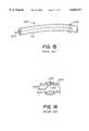
- FIG. 15is a perspective view of a conventional catheter and sensor assembly.
- FIG. 16is a cross-sectional view of the conventional catheter and sensor assembly shown in FIG. 15.
- a core mandrel 10is first selected, as shown in FIG. 1a, over which the catheter will be constructed.
- a catheter liner 12is then placed over the mandrel 10, as shown in FIG. 1b.
- the liner 12can be formed of a variety of different materials but is generally less than 20% of the intended wall thickness. As an example, a liner having a 0.00150 inch wall thickness of TFE can be used. Alternatively, the process of the present invention can be performed without a liner, whereby a polymer coating is applied directly over the mandrel 10.
- a combination of reinforcement filament and polymer materialis then applied over the liner 12, as shown in FIGS. 1c and 1d.
- the mandrel/liner combinationis loaded into rotating chucks 14.
- a filament winding head 16is then traversed on a screw carrier 18 longitudinally along the mandrel 10 to apply fibrous reinforcement filament 20 over the mandrel at a winding angle range of 0 to 90 degrees relative to the longitudinal axis of the catheter (this is a far superior range than achieved in current braiding/wrapping operations).
- a very tight winding angle (e.g., 80 to 90 degrees) of the reinforcement filament 20can be used, and for portions of the catheter that require low rigidity, the reinforcement filament 20 can be applied in a low winding angle (e.g., 0 to 10 degrees).
- the winding angle of the reinforcement fiber 20can be continuously varied over the length of the catheter by controlling the rotation speed of the mandrel 10 and the movement of the filament winding head 16 along the support 18.
- FIG. 2A detail of the winding head 16 is shown in FIG. 2.
- the winding head 16is constructed so that the mandrel/liner is supported by a grooved member 17 during winding to keep the mandrel 10 from bending due to the tension in the reinforcement fiber 20.
- the grooved member 17includes an opening 17a through which the fiber 20 is passed from a spool 21 of the winding head 16 to the liner 12.
- a groove 17bis formed in the member 17 on both sides of the opening 17a for receiving and supporting the mandrel/liner.
- an atomizing spray head 22also traverses the mandrel/liner, as shown in FIG. 1d.
- the spray head 22applies an atomized spray (e.g., a molten polymer in an inert gas stream) that thermally fuses to the substrate it impinges upon (i.e., the mandrel 10, the liner 12, or the reinforcement fiber 20).
- the substratecan be preheated to ensure complete fusion of the sprayed polymer to the substrate. This preheating can be accomplished with infrared, hot air, or resistance heating of the core mandrel 10 or other suitable means.
- the atomized spray head 22according to a first embodiment of the present invention is shown in detail in FIG. 3.
- high pressure gassuch as nitrogen
- a temperature sensor 25such as a thermocouple, is provided in the flow within the spray head 22 to monitor the gas temperature.
- a temperature controller 26is used to maintain the desired temperature of the gas flowing through the venturi 24.
- the throat 27 of the venturi 24is connected to a digitally controlled metering valve 28, which in turn is connected to multiple containers 30, 31 of plastic powders or the like having varying hardness and also to a container 32 of opacifying powder such as tungsten.
- the atomizing spray head 22traverses along a path parallel to the axis of the rotating mandrel/liner. As it traverses this path, the metering valve 28 is set such that only the harder polymer (e.g., from the container 30) is applied at what will be the proximal end of the catheter. As the head 22 traverses the mandrel/liner, the metering valve 28 is controlled such that it ports to the harder polymer to a lesser degree and to the softer polymer (e.g., from the container 31) to a higher degree until finally only the softest polymer is applied at the distal tip of the catheter, which will serve as the soft tip of the catheter-body.
- the metering valve 28is set such that only the harder polymer (e.g., from the container 30) is applied at what will be the proximal end of the catheter.
- the metering valve 28is controlled such that it ports to the harder polymer to a lesser degree and to the softer polymer (e.g.
- opacifying powdercan be selectively applied from the container 32.
- a single layer of polymercan be applied as the filaments are placed.
- the single layer of polymercan be followed by a layer of opacifier and finally a finish layer of polymer.
- a significant benefit of applying opacifier in this manneris that the movement of the head 22 can be paused momentarily to apply circumferential rings 34 of high opacifier concentration, as shown in FIG. 4.
- the circumferential rings 34serve as markers on the catheter when the catheter is used under X-ray.
- the opacifier powder in this embodimentcan be heated to a high enough temperature so that it melts the substrate it impinges upon and thereby adheres to the surface of the substrate until it is overcoated with a finish layer of polymer.
- the catheteris rough-sized by passing a cutter over the surface of the catheter and then polished.
- the catheter bodyis then removed from the rotating chucks 14 and is ready for finishing operations, such as curving or hubbing.
- FIG. 5A second embodiment of the invention will next be described by making reference to FIG. 5 of the drawings.
- the catheter manufacturing method according to the present inventionis performed by applying an unmelted polymer powder to a heated mandrel/liner.
- the mandrel 10' and liner 12are heated by a heater 23' to above the melting point of the powder material (e.g., above 380 degrees F for plastic powder).
- the heater 23'can be a resistance heater controlled by a heater controller 26', as shown in FIG. 5.
- the heatercan be an infrared or hot air heater, or other suitable means for heating the mandrel 10' or liner 12 to the required temperature for melting the powder material.
- the unmelted powderis then sprayed onto the surface of the heated mandrel 10' or liner 12 using the spray head 22'.
- the metering valve 28operates as described above to selectively dispense powder materials from containers 30, 31 and 32 to form a catheter having a continuously variable hardness and opacifier content.
- the mandrel 10'is preferably grounded through a ground G, and the powder material is charged through a positive source +V as the unmelted powder is applied, thereby causing the powder to electrostatically cling to the heated mandrel 10' or liner 12 during application.
- the powderimpinges upon the heated mandrel 10' or liner 12
- the powdermelts to form a uniform coating over the surface thereof.
- a series of fine coating layerscan be applied over the mandrel 10' or liner 12 by making several passes of the spray head 22' over the length or selected portions of the catheter.
- the coated mandrel or linercan then be baked to further consolidate and cure the coating as necessary.
- FIG. 6shows a third embodiment wherein the process according to the present invention is used to form a continuous length of tubing by feeding a continuous core mandrel 40 through a series of rotating tables 42, 44.
- Each rotating table 42, 44is provided with one or more filament winding and spray heads similar to those described above.
- FIGS. 7a and 7bshow a laser arrangement 50 for sizing the tubing after the polymer coating is consolidated on the liner/mandrel.
- the laser arrangement 50includes a laser cutter 51 which can be moved along a threaded shaft 52 or the like for movement parallel to the rotating mandrel 10.
- the laser cutter 51emits a laser beam 53 (e.g., an ultraviolet laser beam) which is directed to impinge on a tangential surface of the polymer coating 54.
- the laser beam 53provides a means for sizing the tubing using laser energy without mechanically contacting the tubing. By eliminating mechanical contact with the rotating tubing, the tubing can be sized with greater precision and without the inherent defects caused by deflections in the mandrel during mechanical cutting and grinding operations.
- the laser cutter 51can also be controlled to taper the catheter over its length.
- FIGS. 8a and 8bshow an apparatus 60 according to a fourth embodiment of the present invention for manufacturing medical tubing having multiple lumens.
- a plurality of mandrels 61, 62are loaded side-by-side into rotating chucks 64 and extend parallel to each other.
- a spray head 65 or other application meansis then used to apply a selected mix of polymer powders and opacifiers from containers 66, 67, and 68 to the mandrels 61, 62, each of which can be heated to consolidate the powder upon impact.
- Each of the mandrels 61, 62defines a lumen through the multiple lumen catheter formed by the process.
- FIG. 8bshows a laser arrangement for sizing the multiple lumen tubing after the polymer coating 69 is consolidated on the mandrels 61, 62, 63.
- the laser arrangementincludes a laser cutter 70 that emits a laser beam 71 which is directed to impinge on a tangential surface of the polymer coating 69.
- the laser arrangement shown in FIG. 8bis similar to the laser arrangement shown in FIGS. 7a and 7b.
- FIG. 9shows an apparatus 80 according to a fifth embodiment of the present invention wherein a fluidized bed 81 is used to apply a polymer coating over a mandrel 82.
- the fluidized bed 81receives a selected ratio of polymers and opacifiers from a plurality of containers 83, 84, 85.
- a digitally controlled valve 86 or the likeis controlled by a mix controller 87 to port to the different containers 83, 84, 85 to adjust the mixture in the fluidized bed 81.
- the fluidized bed 81is connected through a conduit 88 to a source of air or other suitable fluid which is blown through several openings in a bottom surface of the bed 81 to create a "boiling froth" of the mixture in the bed 81.
- the mandrel 82is heated and rotated as it passes through the fluidized bed 81 to cause the polymer mixture in the fluidized bed 81 to consolidate and cling to the mandrel 82 to form a uniform layer.
- a plurality of polymer layers having a selected hardnesscan be applied over the mandrel 82 using the fluidized bed 81 to create a catheter having an optimized hardness at each portion along its length.
- the different hardness polymers used in the manufacturing process according to the present inventioncan be colored to provide visual confirmation of the transition of hardness, as shown in FIG. 10.
- the "hard" polymer in the container 30can be blue and the "soft" polymer in the container 31 can be yellow, thereby causing the most rigid portion 90 of the catheter to be blue, the softest portion 91 of the catheter to be yellow, and the intermediate portions 92, 93, 94 of the catheter to be different shades of green depending on the relative proportions of each polymer applied.
- the present inventionis particularly useful for manufacturing catheters having a conductor wire and sensor formed therein.
- a series of process steps for manufacturing such a catheterare shown in FIGS. 11a through 11f.
- the first three process steps, as shown in FIGS. 11a, 11b, and 11c,correspond to the first three process steps shown in FIGS. 1a, 1b, and 1c, as described above.
- a catheter liner or first layer of polymer material 12is placed over the core mandrel 10 (FIG. 11b), and then covered by a first layer of reinforcement filament 20 (FIG. 11c).
- a conductor wire 100 and sensor 101are then placed on top of the first layer of reinforcement filament 20, as shown in FIG. 11d.
- a second layer of reinforcement filament 20'is then wound over the conductor wire 100 (FIG. 11e), thereby securing the conductor wire 100 and sensor 101 in a selected position.
- the winding angle of the reinforcement fibers 20, 20'can be continuously varied over the length of the catheter by controlling the rotation speed of the mandrel 10 and the movement of the filament winding head 16 along the support 18.
- a final coating of polymer materialis then applied using the spray head 22 in the manner described above (FIG. 11f).
- the conductor wire 100is thus embedded in the wall of the catheter while the wall is being formed, thereby eliminating the difficult assembly process required by the conventional catheter and sensor assembly.
- the conductor wire 100is sandwiched between the two layers of reinforcement fibers 20, 20', and the sensor 101 is positioned flush with the outer surface of the catheter.
- a single point sensor 101'rather than a band-shaped sensor, can be placed in the wall of the catheter, as shown in FIG. 13. Such a single point sensor was not possible with the conventional catheter assembly.
- the sensors 101, 101' placed in the wall of the catheter according to the present inventioncan be in the form of pressure transducers, surface electrodes, capacitive electrodes/plates, temperature sensors, strain gauges, and so forth.
- FIG. 14is a cross-sectional view of a catheter according to the present invention wherein a longitudinally extending passage is formed in a wall of the catheter by embedding a polyimide tube 110 or the like in the wall as the catheter is formed by the process described above.
- a resilient fibersuch as a spring temper wire 111, is inserted through the lumen of the tube 110 and has a distal end 112 embedded and anchored in a distal end of the catheter wall.
- the wire 111is sized such that it would be freely slideable in the tube 110 if the wire 111 was not anchored at its distal end 112.
- the cathetercan be deflected or bent by applying a pushing or pulling force to a proximal end 113 of the wire 111.
- the catheter wallis preferably formed with a varying hardness along its length, whereby a soft portion 114 of the wall is at the distal end of the catheter, and a hard portion 115 of the wall is at the proximal end of the catheter.
- a pulling forceis applied to the proximal end 113 of the wire 111, the soft portion 114 of the catheter will deflect to "steer" the distal end of the catheter in a controlled manner.
- a suitable polyimide tube for use as the tube 110can have, for example, an inside diameter of 0.008 inch and an outside diameter of 0.009 inch.
- the wire 111 inserted through the tube 110can be, for example, a spring temper wire having a 0.006 inch diameter.
- the reinforcement fiberscan be omitted in any of the above-described embodiments.
- the processcan be performed with or without a prefabricated liner placed over the mandrel. If a liner is not used, a thin layer of polymer can be applied over the metal surface of the mandrel using the spray head or other application means according to the present invention. The thin layer of polymer can then function as a liner over which the reinforcement fiber can be wound.
- the mandrelcan be heated and dipped into one or more containers containing the desired ratios of polymer powders.
- the heated mandrelwill cause the powder to consolidate and cling to the mandrel as it is dipped into each container.
- the shearing action of the melt/powder interfacewill provide excellent "wet out" (solid-liquid-solid curing) of high viscosity polymers.
- the length of time of immersioncan be used to control the buildup or thickness of the polymer material on the mandrel.
- the polymer powdercan also be applied to the heated mandrel using a spatula or the like.
- the consolidated powdercan then be sized and finished using a laser or other cutting means as described above.
- the present inventionprovides a low cost method for manufacturing both simple and complex catheters.
- the disclosed methodcan be used to make a straight catheter tube that has no change in hardness and nothing embedded in the wall, or a complex catheter having any combination of the following features: (1) a variable hardness of plastic along a length of the catheter; (2) a fibrous reinforcement having a constant or variable pitch, a constant or variable number of fibers, and one or more different types of fibers; (3) sensors and conductor wires placed in the catheter wall as the wall is fabricated; (4) a deflection passage and wire embedded in the catheter wall for steering the catheter; and (5) multiple lumens having the same or different diameters.
Landscapes
- Engineering & Computer Science (AREA)
- Health & Medical Sciences (AREA)
- Life Sciences & Earth Sciences (AREA)
- Mechanical Engineering (AREA)
- Hematology (AREA)
- Animal Behavior & Ethology (AREA)
- Pulmonology (AREA)
- Anesthesiology (AREA)
- Biomedical Technology (AREA)
- Heart & Thoracic Surgery (AREA)
- Optics & Photonics (AREA)
- Biophysics (AREA)
- General Health & Medical Sciences (AREA)
- Public Health (AREA)
- Veterinary Medicine (AREA)
- Physics & Mathematics (AREA)
- Wood Science & Technology (AREA)
- Plasma & Fusion (AREA)
- Media Introduction/Drainage Providing Device (AREA)
- Materials For Medical Uses (AREA)
Abstract
Description
This application claims priority from provisional U.S. Application Ser. No. 60/024,344, filed Aug. 23, 1996.
1. Field of the Invention
The present invention relates generally to an apparatus and method for manufacturing tubing and, more particularly, to an apparatus and method for manufacturing catheters having a simple or complex configuration by applying a nonextruded layer of polymer material over a core member.
2. Description of the Related Art
Medical tubing and catheters are widely employed for a variety of treatment and diagnostic procedures involving, for example, the administration of fluid medications and devices into a patient and the removal of fluids from the patient. In this application, the terms "catheter" and "medical tubing" will be used interchangeably to refer to the same structure.
The ultimate use for which medical tubing is designed requires that the tubing have certain physical characteristics. For example, a catheter must be sufficiently stiff or rigid to enable its insertion and movement through narrow body orifices and channels and, in some applications, must also be able to withstand a high bursting pressure. On the other hand, a catheter must be sufficiently soft and flexible so that it may readily conform to body shapes so as not to cause injury to the interior wall of a patient's vessel as it is advanced. In addition, a catheter must be of sufficient mechanical strength to resist tearing during normal use, such as when the catheter is removed against tissue resistance.
Catheters have been manufactured for several years by numerous methods. Mechanical performance requirements of catheters have increased over time because of new procedures, such as angioplasty and therapeutic and diagnostic neurological procedures. In these applications, it is desirable to have a catheter that varies in hardness along its shaft length. Conventional methods to meet this requirement consist of segmenting the wall of the catheter with plastics having varying hardness. The segments are generally individual tubes bonded together, or segments of varying hardness within a laminated-type construction. The transition from hard to soft polymer in these types of constructions is abrupt and may require many segments to achieve the desired hardness transition, which complicates manufacture.
Other methods for manufacturing catheters having varying hardness along the length of the catheter have been disclosed. For example, U.S. Pat. No. 4,385,635 (RUIZ) and U.S. Pat. No. 5,085,649 (FLYNN) each discloses a catheter tubing having tapered resin layers of different hardness. The tapered layers are formed by a controlled extrusion process using, for example, a bi-orifice extrusion head with a controlled discharge rate to keep the combined thickness of the respective layers constant. Because these methods rely on an extrusion process to form the tapered layers, they are relatively expensive to implement and are difficult to control in a manner that achieves an optimum hardness transition over the length of the catheter. The tapered layers also tend to make it difficult to incorporate reinforcement filament into the catheter during manufacturing.
Catheters are often employed for diagnostic procedures that require sensors to be placed within body orifices. An example of onesuch catheter 200 is shown in FIGS. 15 and 16. In this conventional catheter, atubing 201 is first formed using a conventional extrusion process or the like. Ahole 202 is then formed in thewall 203 of thetubing 201. Aconductor wire 204 is then inserted through the lumen of thetubing 201 and out through the hole 202 (or vice versa). Asurface electrode 205 in the form of a metal band is electrically connected to theconductor wire 204 and placed over thehole 202 around the outer surface of thecatheter 200. Thesurface electrode 204 functions as a sensor.
This conventional sensor arrangement for catheters has a number of disadvantages. Theconductor wire 204 is placed within the lumen of thecatheter 200, thereby interfering with the passage of fluids and the like through the lumen. The process of assembling theconductor wire 204 andsurface electrode 205 to thecatheter 200 is quite difficult since thecatheter 200 is formed separately from the sensor and conductor wire.
Nylon powders are commercially available for use as painting or chrome alternatives to eliminate harmful emissions and waste products during metal plating operations, for example. These nylon powders have been applied using electrostatic/baking applications that produce films over metal substrates and the like having a thickness in the range of 0.004 to 0.050 inches. In conventional applications of the powders, the substrate is grounded, the plastic powder is charged and applied with a spray or fluidized bed exposure, and then the powder-coated substrate is baked. This known technology has not previously been adopted in a catheter manufacturing process.
An object of the present invention is to solve the problems associated with the prior art catheter manufacturing methods described above.
More specifically, an object of the present invention is to provide a cost effective process and apparatus for manufacturing catheters having a simple or complex configuration.
It is a further object of the present invention to provide a process and apparatus for manufacturing catheters having a continuous change in hardness over the length of the catheter.
It is a further object of the present invention to provide a process and apparatus for manufacturing catheters using a polymer material in a particulate preform without using an extrusion process.
It is a further object of the present invention to provide a process and apparatus for manufacturing catheters which permits great flexibility in the composition of the catheter walls, the size and number of lumen, the placement of opacifier markers, the hardness over the length of the catheter, and the placement of fibrous reinforcement, conductors, sensors, and deflection passages in the catheter walls.
Additional objects, advantages and novel features of the invention will be set forth in part in the description that follows, and in part will become apparent to those skilled in the art upon examination of the following or may be learned by practice of the invention. The objects and advantages of the invention may be realized and attained by means of the instrumentalities and combinations particularly pointed out in the appended claims.
The present invention provides an apparatus and method for manufacturing catheters that produces an improved catheter, having a simple or complex configuration, by applying a nonextruded layer of polymer material in a particulate preform over a length of a core member. The polymer material can be provided in the form of a powder, such as thermoplastic or thermosets, or in the form of a solvenated polymer, such as urethanes, epoxies, polyimides, and so forth.
Since the polymer material is applied in a nonextrusion process, the composition of the polymer material can be varied continuously as it is being applied to thereby provide a variable hardness over the length of the catheter. A fibrous reinforcement can be used having a constant or variable pitch and a constant or variable number of fibers and fiber types. Sensors can be easily placed in a wall of the catheter as the catheter is being fabricated, thereby allowing more sensors to be used without placing conductors in the lumen of the catheter. Deflection passages can be provided in a wall of the catheter for inserting a wire to deflect the catheter. The core member can be a mandrel or a liner placed over a mandrel.
In the preferred embodiment, a mandrel is rotated about its longitudinal axis while a spray head and a filament winding head traverse the length of the mandrel and cover the mandrel with layers of polymer and filament, respectively. According to another embodiment, a continuous core mandrel is used, and a spray head and filament winding head are mounted for rotation around the continuous core mandrel. According to yet another embodiment, a heated core member is immersed in a fluidized bed or other suitable container to apply the polymer coating over the core member. A plurality of mandrels can be placed side-by-side to form a multiple lumen tubing. A conventional or laser sizing arrangement is used to provide final sizing of the catheter without contacting the catheter mechanically.
The polymer material can be consolidated onto the core substrate by heating the polymer material into a molten state before applying it to the core substrate, or by heating the core substrate and applying the polymer material in powder form. In the latter method, the polymer material is melted and consolidated over the surface of the core substrate as it impacts on the core substrate.
More specifically, a first aspect of the present invention comprises a method of making medical tubing, comprising the steps of providing a core having an outer surface, providing a polymer material in a particulate preform, and applying a nonextruded layer of the polymer material in its particulate preform over a length of the outer surface of the core. The method may further comprise the step of varying a composition of the polymer material while the layer of polymer material is being applied to thereby provide the layer of polymer material with a variable hardness over at least a portion of a length of the core.
A liner may be placed over a core mandrel before applying the layer of polymer material, wherein the liner functions as the core. The invention can also be practiced by applying the layer of polymer material directly to the core mandrel. The composition of the polymer material can be varied by mixing two or more polymer materials each having a different hardness, and changing a ratio of the first polymer material to the second polymer material as the layer of polymer material is applied. An opacifier material can also be selectively mixed with the polymer materials and applied in a uniform layer over the catheter or in the form of opacifier rings selectively spaced along the length of the catheter. Several other variations and details of the method according to this aspect of the present invention are described in the detailed description provided below.
A second aspect of the present invention comprises an apparatus for manufacturing medical tubing, comprising a core having an outer surface, a supply of polymer material in a particulate preform, and means for applying a nonextruded layer of the polymer material in its particulate preform over a length of the outer surface of the core. The apparatus may also have a means for varying a composition of the polymer material while the layer of polymer material is being applied to thereby provide a variable hardness over at least a portion of a length of the tubing. Several variations and details of the apparatus according to this aspect of the present invention are described below.
A third aspect of the present invention comprises an improved catheter comprising a nonextruded layer of polymer material having a continuously changing hardness over at least a portion of a length of the catheter. The catheter may comprise a liner over which the layer of polymer material is placed. The layer of polymer material preferably has a uniform thickness over a length of the catheter, and a reinforcement filament embedded within the layer of polymer material. Opacifier marks may be selectively spaced over the length of the catheter.
The layer of polymer material in the catheter can comprise different color shades corresponding to different ratios of polymers used in the layer of polymer material, thereby providing a visual indication of a hardness transition. The catheter comprises either a single lumen or multiple lumens extending therethrough. In one variation, a conductor and sensor can be embedded in the layer of polymer material. In another variation, a longitudinal deflection passage can be formed in the layer of polymer material with a resilient fiber extending through the passage and anchored adjacent a distal end of the passage, whereby the catheter can be deflected by applying a force to a proximal end of the resilient fiber. Other variations and details of the improved catheter according to this aspect of the present invention are described below.
Preferred embodiments of the present invention will be described in detail hereinafter with reference to the accompanying drawings. In the drawings:
FIGS. 1a, 1b, 1c and 1d show a series of process steps for manufacturing a catheter according the present invention.
FIG. 2 is a perspective detail view showing a winding head used in the present invention.
FIG. 3 is a sectional view of an atomizing spray head for applying a molten material to a catheter liner according to a first embodiment of the present invention.
FIG. 4 is a perspective view of a catheter manufactured by the present invention having evenly spaced opacifier marks.
FIG. 5 is a sectional view of an arrangement for applying a powder material to a heated mandrel/liner according to a second embodiment of the present invention.
FIG. 6 is a perspective view of a third embodiment of the present invention wherein a series of rotating fiber and spray heads are used to manufacture catheters using a continuous core mandrel.
FIGS. 7a and 7b show a laser arrangement in perspective and sectional views, respectively, for sizing the tubing without mechanical contact after the polymer coating is consolidated over the mandrel.
FIGS. 8a and 8b show a fourth embodiment of the present invention which is used to manufacture medical tubing having multiple lumens.
FIG. 9 shows a fifth embodiment of the present invention wherein a fluidized bed is used to apply a polymer coating to the mandrel.
FIG. 10 shows a catheter having different color shades indicating the transition in hardness over the length of the catheter.
FIGS. 11a, 11b, 11c, 11d, 11e and 11f show a series of process steps for manufacturing a catheter having a conductor wire and a sensor embedded in a wall of the catheter.
FIG. 12 is a cross-sectional view of a catheter according to the present invention wherein a conductor wire and sensor are embedded in a wall of the catheter.
FIG. 13 is a perspective view of a catheter having a single point sensor and conductor wire embedded in a wall of the catheter.
FIG. 14 is a cross-sectional view of a catheter according to the present invention wherein a deflection passage and resilient fiber are embedded in a wall of the catheter for deflecting the catheter.
FIG. 15 is a perspective view of a conventional catheter and sensor assembly.
FIG. 16 is a cross-sectional view of the conventional catheter and sensor assembly shown in FIG. 15.
Preferred embodiments of the invention will now be described in detail with reference to FIGS. 1 to 14 of the drawings.
The basic method of manufacture according to a first embodiment of the present invention will be described below by making reference to FIGS. 1a to 1d. According to the method, acore mandrel 10 is first selected, as shown in FIG. 1a, over which the catheter will be constructed.
Acatheter liner 12 is then placed over themandrel 10, as shown in FIG. 1b. Theliner 12 can be formed of a variety of different materials but is generally less than 20% of the intended wall thickness. As an example, a liner having a 0.00150 inch wall thickness of TFE can be used. Alternatively, the process of the present invention can be performed without a liner, whereby a polymer coating is applied directly over themandrel 10.
A combination of reinforcement filament and polymer material is then applied over theliner 12, as shown in FIGS. 1c and 1d. During this operation, the mandrel/liner combination is loaded into rotating chucks 14. Afilament winding head 16 is then traversed on a screw carrier 18 longitudinally along themandrel 10 to applyfibrous reinforcement filament 20 over the mandrel at a winding angle range of 0 to 90 degrees relative to the longitudinal axis of the catheter (this is a far superior range than achieved in current braiding/wrapping operations). For portions of the catheter that require great circumferential rigidity or kink resistance, a very tight winding angle (e.g., 80 to 90 degrees) of thereinforcement filament 20 can be used, and for portions of the catheter that require low rigidity, thereinforcement filament 20 can be applied in a low winding angle (e.g., 0 to 10 degrees). The winding angle of thereinforcement fiber 20 can be continuously varied over the length of the catheter by controlling the rotation speed of themandrel 10 and the movement of thefilament winding head 16 along the support 18.
A detail of the windinghead 16 is shown in FIG. 2. As seen in FIG. 2, the windinghead 16 is constructed so that the mandrel/liner is supported by agrooved member 17 during winding to keep themandrel 10 from bending due to the tension in thereinforcement fiber 20. Thegrooved member 17 includes anopening 17a through which thefiber 20 is passed from aspool 21 of the windinghead 16 to theliner 12. Agroove 17b is formed in themember 17 on both sides of theopening 17a for receiving and supporting the mandrel/liner.
At either the same time, or after winding, an atomizing spray head 22 also traverses the mandrel/liner, as shown in FIG. 1d. The spray head 22 applies an atomized spray (e.g., a molten polymer in an inert gas stream) that thermally fuses to the substrate it impinges upon (i.e., themandrel 10, theliner 12, or the reinforcement fiber 20). The substrate can be preheated to ensure complete fusion of the sprayed polymer to the substrate. This preheating can be accomplished with infrared, hot air, or resistance heating of thecore mandrel 10 or other suitable means.
The atomized spray head 22 according to a first embodiment of the present invention is shown in detail in FIG. 3. As shown, high pressure gas, such as nitrogen, is piped past a heater 23 and through a venturi 24 of the spray head 22. Atemperature sensor 25, such as a thermocouple, is provided in the flow within the spray head 22 to monitor the gas temperature. A temperature controller 26 is used to maintain the desired temperature of the gas flowing through the venturi 24.
The throat 27 of the venturi 24 is connected to a digitally controlled metering valve 28, which in turn is connected tomultiple containers 30, 31 of plastic powders or the like having varying hardness and also to a container 32 of opacifying powder such as tungsten.
While the mandrel/liner is spinning, the atomizing spray head 22 traverses along a path parallel to the axis of the rotating mandrel/liner. As it traverses this path, the metering valve 28 is set such that only the harder polymer (e.g., from the container 30) is applied at what will be the proximal end of the catheter. As the head 22 traverses the mandrel/liner, the metering valve 28 is controlled such that it ports to the harder polymer to a lesser degree and to the softer polymer (e.g., from the container 31) to a higher degree until finally only the softest polymer is applied at the distal tip of the catheter, which will serve as the soft tip of the catheter-body.
In a similar fashion, opacifying powder can be selectively applied from the container 32. A single layer of polymer can be applied as the filaments are placed. The single layer of polymer can be followed by a layer of opacifier and finally a finish layer of polymer. A significant benefit of applying opacifier in this manner is that the movement of the head 22 can be paused momentarily to apply circumferential rings 34 of high opacifier concentration, as shown in FIG. 4. The circumferential rings 34 serve as markers on the catheter when the catheter is used under X-ray. The opacifier powder in this embodiment can be heated to a high enough temperature so that it melts the substrate it impinges upon and thereby adheres to the surface of the substrate until it is overcoated with a finish layer of polymer.
After the catheter is completely coated with polymer from the spray head 22, the catheter is rough-sized by passing a cutter over the surface of the catheter and then polished. The catheter body is then removed from the rotating chucks 14 and is ready for finishing operations, such as curving or hubbing.
A second embodiment of the invention will next be described by making reference to FIG. 5 of the drawings. As shown in FIG. 5, the catheter manufacturing method according to the present invention is performed by applying an unmelted polymer powder to a heated mandrel/liner.
In this embodiment, the mandrel 10' andliner 12 are heated by a heater 23' to above the melting point of the powder material (e.g., above 380 degrees F for plastic powder). The heater 23' can be a resistance heater controlled by a heater controller 26', as shown in FIG. 5. Alternatively, the heater can be an infrared or hot air heater, or other suitable means for heating the mandrel 10' orliner 12 to the required temperature for melting the powder material.
The unmelted powder is then sprayed onto the surface of the heated mandrel 10' orliner 12 using the spray head 22'. The metering valve 28 operates as described above to selectively dispense powder materials fromcontainers 30, 31 and 32 to form a catheter having a continuously variable hardness and opacifier content. As shown in FIG. 5, the mandrel 10' is preferably grounded through a ground G, and the powder material is charged through a positive source +V as the unmelted powder is applied, thereby causing the powder to electrostatically cling to the heated mandrel 10' orliner 12 during application. When the powder impinges upon the heated mandrel 10' orliner 12, the powder melts to form a uniform coating over the surface thereof. A series of fine coating layers can be applied over the mandrel 10' orliner 12 by making several passes of the spray head 22' over the length or selected portions of the catheter. The coated mandrel or liner can then be baked to further consolidate and cure the coating as necessary.
FIG. 6 shows a third embodiment wherein the process according to the present invention is used to form a continuous length of tubing by feeding acontinuous core mandrel 40 through a series of rotating tables 42, 44. Each rotating table 42, 44 is provided with one or more filament winding and spray heads similar to those described above.
FIGS. 7a and 7b show alaser arrangement 50 for sizing the tubing after the polymer coating is consolidated on the liner/mandrel. As shown, thelaser arrangement 50 includes a laser cutter 51 which can be moved along a threaded shaft 52 or the like for movement parallel to therotating mandrel 10. The laser cutter 51 emits a laser beam 53 (e.g., an ultraviolet laser beam) which is directed to impinge on a tangential surface of the polymer coating 54. The laser beam 53 provides a means for sizing the tubing using laser energy without mechanically contacting the tubing. By eliminating mechanical contact with the rotating tubing, the tubing can be sized with greater precision and without the inherent defects caused by deflections in the mandrel during mechanical cutting and grinding operations. The laser cutter 51 can also be controlled to taper the catheter over its length.
FIGS. 8a and 8b show anapparatus 60 according to a fourth embodiment of the present invention for manufacturing medical tubing having multiple lumens. As shown in FIG. 8a, a plurality of mandrels 61, 62 are loaded side-by-side into rotating chucks 64 and extend parallel to each other. Aspray head 65 or other application means is then used to apply a selected mix of polymer powders and opacifiers from containers 66, 67, and 68 to the mandrels 61, 62, each of which can be heated to consolidate the powder upon impact. Each of the mandrels 61, 62 defines a lumen through the multiple lumen catheter formed by the process.
FIG. 8b shows a laser arrangement for sizing the multiple lumen tubing after the polymer coating 69 is consolidated on the mandrels 61, 62, 63. As shown, the laser arrangement includes a laser cutter 70 that emits a laser beam 71 which is directed to impinge on a tangential surface of the polymer coating 69. The laser arrangement shown in FIG. 8b is similar to the laser arrangement shown in FIGS. 7a and 7b.
FIG. 9 shows an apparatus 80 according to a fifth embodiment of the present invention wherein a fluidized bed 81 is used to apply a polymer coating over a mandrel 82. The fluidized bed 81 receives a selected ratio of polymers and opacifiers from a plurality of containers 83, 84, 85. A digitally controlled valve 86 or the like is controlled by a mix controller 87 to port to the different containers 83, 84, 85 to adjust the mixture in the fluidized bed 81. The fluidized bed 81 is connected through a conduit 88 to a source of air or other suitable fluid which is blown through several openings in a bottom surface of the bed 81 to create a "boiling froth" of the mixture in the bed 81. The mandrel 82 is heated and rotated as it passes through the fluidized bed 81 to cause the polymer mixture in the fluidized bed 81 to consolidate and cling to the mandrel 82 to form a uniform layer. As in the other embodiments, a plurality of polymer layers having a selected hardness can be applied over the mandrel 82 using the fluidized bed 81 to create a catheter having an optimized hardness at each portion along its length.
The different hardness polymers used in the manufacturing process according to the present invention can be colored to provide visual confirmation of the transition of hardness, as shown in FIG. 10. For example, the "hard" polymer in thecontainer 30 can be blue and the "soft" polymer in the container 31 can be yellow, thereby causing the most rigid portion 90 of the catheter to be blue, the softest portion 91 of the catheter to be yellow, and the intermediate portions 92, 93, 94 of the catheter to be different shades of green depending on the relative proportions of each polymer applied.
The present invention is particularly useful for manufacturing catheters having a conductor wire and sensor formed therein. A series of process steps for manufacturing such a catheter are shown in FIGS. 11a through 11f. The first three process steps, as shown in FIGS. 11a, 11b, and 11c, correspond to the first three process steps shown in FIGS. 1a, 1b, and 1c, as described above. In these first process steps, a catheter liner or first layer ofpolymer material 12 is placed over the core mandrel 10 (FIG. 11b), and then covered by a first layer of reinforcement filament 20 (FIG. 11c).
A conductor wire 100 and sensor 101 are then placed on top of the first layer ofreinforcement filament 20, as shown in FIG. 11d. A second layer of reinforcement filament 20' is then wound over the conductor wire 100 (FIG. 11e), thereby securing the conductor wire 100 and sensor 101 in a selected position. As described above, the winding angle of thereinforcement fibers 20, 20' can be continuously varied over the length of the catheter by controlling the rotation speed of themandrel 10 and the movement of thefilament winding head 16 along the support 18. A final coating of polymer material is then applied using the spray head 22 in the manner described above (FIG. 11f).
The conductor wire 100 is thus embedded in the wall of the catheter while the wall is being formed, thereby eliminating the difficult assembly process required by the conventional catheter and sensor assembly. As shown in FIG. 12, the conductor wire 100 is sandwiched between the two layers ofreinforcement fibers 20, 20', and the sensor 101 is positioned flush with the outer surface of the catheter. Alternatively, a single point sensor 101', rather than a band-shaped sensor, can be placed in the wall of the catheter, as shown in FIG. 13. Such a single point sensor was not possible with the conventional catheter assembly.
The sensors 101, 101' placed in the wall of the catheter according to the present invention can be in the form of pressure transducers, surface electrodes, capacitive electrodes/plates, temperature sensors, strain gauges, and so forth.
FIG. 14 is a cross-sectional view of a catheter according to the present invention wherein a longitudinally extending passage is formed in a wall of the catheter by embedding a polyimide tube 110 or the like in the wall as the catheter is formed by the process described above. A resilient fiber, such as a spring temper wire 111, is inserted through the lumen of the tube 110 and has a distal end 112 embedded and anchored in a distal end of the catheter wall. The wire 111 is sized such that it would be freely slideable in the tube 110 if the wire 111 was not anchored at its distal end 112.
The catheter can be deflected or bent by applying a pushing or pulling force to a proximal end 113 of the wire 111. The catheter wall is preferably formed with a varying hardness along its length, whereby a soft portion 114 of the wall is at the distal end of the catheter, and a hard portion 115 of the wall is at the proximal end of the catheter. When a pulling force is applied to the proximal end 113 of the wire 111, the soft portion 114 of the catheter will deflect to "steer" the distal end of the catheter in a controlled manner.
A suitable polyimide tube for use as the tube 110 can have, for example, an inside diameter of 0.008 inch and an outside diameter of 0.009 inch. The wire 111 inserted through the tube 110 can be, for example, a spring temper wire having a 0.006 inch diameter.
It should be noted that, in certain applications, the reinforcement fibers can be omitted in any of the above-described embodiments. Also, as mentioned above, the process can be performed with or without a prefabricated liner placed over the mandrel. If a liner is not used, a thin layer of polymer can be applied over the metal surface of the mandrel using the spray head or other application means according to the present invention. The thin layer of polymer can then function as a liner over which the reinforcement fiber can be wound.
The present invention is not limited to only those processes described above for applying polymer powder to the mandrel. For example, in a rather crude arrangement according to the invention the mandrel can be heated and dipped into one or more containers containing the desired ratios of polymer powders. In this case, the heated mandrel will cause the powder to consolidate and cling to the mandrel as it is dipped into each container. The shearing action of the melt/powder interface will provide excellent "wet out" (solid-liquid-solid curing) of high viscosity polymers. The length of time of immersion can be used to control the buildup or thickness of the polymer material on the mandrel. The polymer powder can also be applied to the heated mandrel using a spatula or the like. The consolidated powder can then be sized and finished using a laser or other cutting means as described above.
The present invention provides a low cost method for manufacturing both simple and complex catheters. The disclosed method can be used to make a straight catheter tube that has no change in hardness and nothing embedded in the wall, or a complex catheter having any combination of the following features: (1) a variable hardness of plastic along a length of the catheter; (2) a fibrous reinforcement having a constant or variable pitch, a constant or variable number of fibers, and one or more different types of fibers; (3) sensors and conductor wires placed in the catheter wall as the wall is fabricated; (4) a deflection passage and wire embedded in the catheter wall for steering the catheter; and (5) multiple lumens having the same or different diameters.
It will be appreciated that the present invention is not limited to the exact construction that has been described above and illustrated in the accompanying drawings, and that various modifications and changes can be made without departing from the scope and spirit thereof. It is intended that the scope of the invention protected be limited only by the appended claims.
Claims (35)
1. A method of making medical tubing, comprising the steps of:
providing a core having an outer surface;
providing first and second polymer materials, said first polymer material having a different hardness than said second polymer material;
applying a nonextruded layer comprising a mixture of said first and second polymer materials over a length of said outer surface of the core by spraying said polymer materials toward the core such that particles of said polymer materials cover the outer surface of the core and are consolidated to form the medical tubing; and
changing a mixed ratio of said first polymer material to said second polymer material as said polymer materials ate being sprayed toward the core to provide a continuous transition of hardness over a length of the tubing.
2. The method of making medical tubing according to claim 1, wherein said polymer materials are provided in powder form for applying to said core.
3. The method of making medical tubing according to claim 1, wherein said polymer materials are provided in a solution of solvent for applying to said core.
4. The method of making medical tubing according to claim 1, further comprising the step of placing a liner over a core mandrel before applying the layer of polymer material, said liner comprising said core.
5. The method of making medical tubing according to claim 1, further comprising the step of winding a filament about said core before applying the layer of polymer material.
6. The method of making medical tubing according to claim 1, further comprising the step of rotating the core while applying the layer of polymer material.
7. A method of making medical tubing, comprising the steps of:
providing a core having an outer surface;
providing at least one polymer material;
applying a nonextruded layer of said polymer material over a length of said outer surface of the core such that particles of said polymer material impact on the outer surface of the core and are consolidated to form the medical tubing; and
heating the polymer material into a molten state before the polymer material impacts on the outer surface of said core.
8. The method of making medical tubing according to claim 1, further comprising the steps of heating the core and spraying the polymer materials in powder form onto the heated core, wherein the polymer materials are consolidated on the core as a result of the heated core melting the polymer materials.
9. The method of making medical tubing according to claim 1, further comprising the step of selectively applying opacifier material to said core to form a plurality of opacifier rings along the length of the tubing.
10. The method of making medical tubing according to claim 1, further comprising the step of sizing the tubing by grinding or cutting an outer surface of the tubing after applying the layer of polymer material.
11. The method of making medical tubing according to claim 1, further comprising the step of sizing the tubing by passing a laser beam over a tangential surface of the layer of polymer material.
12. The method of making medical tubing according to claim 1, further comprising the step of providing a spray head to apply the layer of polymer material to the core, and rotating the spray head about the core while applying the polymer material.
13. A method of making medical tubing, comprising the steps of:
providing a core having an outer surface;
providing at least one polymer material;
applying a nonextruded layer of said polymer material over a length of said outer surface of the core such that particles of said polymer material are consolidated to form the medical tubing; and
grounding the core and charging the polymer material to cause the polymer material to cling to the core electrostatically as the polymer material is applied.
14. A method of making medical tubing having multiple lumens; comprising the steps of:
providing a plurality of cores each having an outer surface;
placing said plurality of cores in close proximity to each other;
providing at least one polymer material; and
applying a nonextruded layer of polymer material over a length of said outer surfaces of said plurality of cores such that particles of said polymer material are consolidated to form the medical tubing having multiple lumens.
15. A method of making medical tubing, comprising the steps of:
providing a core having an outer surface:
providing at least one polymer material;
applying a nonextruded layer of said polymer material over a length of said outer surface of the core such that particles of said polymer material are consolidated to form the medical tubing;
placing at least one conductor and at least one sensor over said nonextruded layer of polymer material; and
applying a second nonextruded layer of polymer material over said conductor.
16. The method of making medical tubing according to claim 15, further comprising the steps of:
winding a first filament about said medical tubing before placing said conductor and said sensor;
winding a second filament about said medical tubing after placing said conductor and said sensor; and
applying said second nonextruded layer of polymer material over said filaments and said conductor.
17. A method of making medical tubing, comprising the steps of:
providing a gore having an outer surface;
providing at least one polymer material;
applying a nonextruded layer of said polymer material over a length of said outer surface of the core such that particles of said polymer material are consolidated to form the medical tubing;
forming at least one longitudinal passage in said nonextruded layer of polymer material;
placing a resilient fiber into said longitudinal passage; and
anchoring a distal end of said resilient fiber adjacent a distal end of said longitudinal passage, whereby the medical tubing can be deflected by applying a force to a proximal end of said resilient fiber.
18. A method of making a tubular structure, comprising the steps of:
applying a nonextruded layer of polymer material over a length of a core substrate; and
varying a composition and color of said polymer material while said layer of polymer material is being applied to thereby provide said layer of polymer material with a variable hardness and color over at least a portion of a length of the core substrate, whereby a change in the hardness of the layer of polymer material is indicated by a change in color of the layer of polymer material.
19. The method of making a tubular structure according to claim 18, further comprising the steps of:
mixing a first polymer material with a second polymer material, said first polymer material having a different hardness than said second polymer material; and
changing a mixed ratio of said first polymer material to said second polymer material as said layer of polymer material is applied to provide a variable hardness over a length of the tubular structure.
20. The method of making a tubular structure according to claim 19, further comprising the step of selectively mixing an opacifier material with the first and second polymer materials as said layer of polymer material is applied.
21. The method of making a tubular structure according to claim 18, further comprising the steps of:
providing at least first and second polymers having different hardnesses and different colors; and
selectively mixing said first and second polymers to vary a hardness in the layer of polymer material, whereby a transition in the hardness of the layer of polymer material is indicated by a change in color of the layer of polymer material.
22. The method of making a tubular structure according to claim 18, further comprising the steps of:
forming at least one longitudinal passage in said nonextruded layer of polymer material;
placing a resilient fiber into said longitudinal passage; and
anchoring a distal end of said resilient fiber adjacent a distal end of said longitudinal passage, whereby the tubular structure can be deflected by applying a force to a proximal end of said resilient fiber.
23. A catheter comprising a tubular structure manufactured by the method defined in claim 18.
24. A catheter comprising a nonextruded layer of polymer material having a continuously changing hardness over at least a portion of a length of the catheter, wherein said layer of polymer material comprises different color shades providing a visual indication of hardness.
25. The catheter according to claim 24, further comprising a liner, said layer of polymer material covering an outer surface of said liner.
26. The catheter according to claim 24, wherein said layer of polymer material has a uniform thickness over said portion of the catheter.
27. The catheter according to claim 24, further comprising a reinforcement filament embedded within said layer of polymer material.
28. The catheter according to claim 24, further comprising at least one opacifier mark extending about a circumference of the catheter.
29. The catheter according to claim 24, further comprising a plurality of opacifier marks spaced along the length of the catheter.
30. The catheter according to claim 24, further comprising multiple lumens extending through the catheter.
31. A catheter comprising a nonextruded layer of polymer material having a continuously changing hardness over at least a portion of a length of the catheter, further comprising at least one conductor and at least one sensor embedded in said layer of polymer material.
32. A catheter comprising a nonextruded layer of polymer material having a continuously changing hardness over at least a portion of a length of the catheter, further comprising at least one longitudinal passage embedded in said layer of polymer material and a resilient fiber extending through said longitudinal passage, a distal end of said resilient fiber being anchored adjacent a distal end of the longitudinal passage, whereby the catheter can be deflected by applying a force to a proximal end of said resilient fiber.
33. The method of making medical tubing according to claim 3, wherein said polymer material is consolidated by driving off the solvent.
34. The method of making medical tubing according to claim 10, wherein said step of sizing the tubing comprises grinding or cutting the tubing to have a tapering thickness over a length of the tubing.
35. The method of making medical tubing according to claim 11, wherein said step of sizing the tubing comprises using the laser beam to create a tapering thickness over a length of the tubing.
Priority Applications (1)
| Application Number | Priority Date | Filing Date | Title |
|---|---|---|---|
| US08/918,713US6030371A (en) | 1996-08-23 | 1997-08-22 | Catheters and method for nonextrusion manufacturing of catheters |
Applications Claiming Priority (2)
| Application Number | Priority Date | Filing Date | Title |
|---|---|---|---|
| US2434496P | 1996-08-23 | 1996-08-23 | |
| US08/918,713US6030371A (en) | 1996-08-23 | 1997-08-22 | Catheters and method for nonextrusion manufacturing of catheters |
Publications (1)
| Publication Number | Publication Date |
|---|---|
| US6030371Atrue US6030371A (en) | 2000-02-29 |
Family
ID=21820109
Family Applications (1)
| Application Number | Title | Priority Date | Filing Date |
|---|---|---|---|
| US08/918,713Expired - LifetimeUS6030371A (en) | 1996-08-23 | 1997-08-22 | Catheters and method for nonextrusion manufacturing of catheters |
Country Status (3)
| Country | Link |
|---|---|
| US (1) | US6030371A (en) |
| AU (1) | AU4357697A (en) |
| WO (1) | WO1998007523A1 (en) |
Cited By (126)
| Publication number | Priority date | Publication date | Assignee | Title |
|---|---|---|---|---|
| US6458231B1 (en)* | 1999-03-17 | 2002-10-01 | The United States Of America As Represented By The Secretary Of The Air Force | Method of making microtubes with axially variable geometries |
| US20020156452A1 (en)* | 1996-02-16 | 2002-10-24 | Pursley Matt D. | Method and apparatus for curving catheter with soft distal end |
| US6511462B1 (en)* | 1999-07-16 | 2003-01-28 | Terumo Kabushiki Kaisha | Catheter and method of manufacturing the same |
| US6537480B1 (en)* | 1998-09-11 | 2003-03-25 | Advanced Cardiovascular Systems, Inc. | Method of manufacturing a catheter with a flexible tip and taper |
| US6543132B1 (en)* | 1997-12-18 | 2003-04-08 | Baker Hughes Incorporated | Methods of making mud motors |
| US6554794B1 (en)* | 1997-09-24 | 2003-04-29 | Richard L. Mueller | Non-deforming deflectable multi-lumen catheter |
| US20030109861A1 (en)* | 2001-04-12 | 2003-06-12 | Jin Shimada | Steerable sheath catheters |
| US6579484B1 (en)* | 1999-12-16 | 2003-06-17 | Advanced Cardiovascular Systems, Inc. | Co-extruded taper shaft |
| US6582536B2 (en) | 2000-04-24 | 2003-06-24 | Biotran Corporation Inc. | Process for producing steerable sheath catheters |
| US20030230822A1 (en)* | 2002-06-14 | 2003-12-18 | Ross Bartholomew | Wave molding method and apparatus for manufacturing cannulae |
| US20030230823A1 (en)* | 2002-06-14 | 2003-12-18 | Ross Bartholomew | Dispense molding method and apparatus for manufacturing cannulae |
| US6740277B2 (en) | 2002-04-24 | 2004-05-25 | Becton Dickinson And Company | Process of making a catheter |
| US6742952B1 (en) | 2003-02-28 | 2004-06-01 | Bic Corporation | Transparent or translucent tubular structure |
| US20040126481A1 (en)* | 2002-12-30 | 2004-07-01 | Jan Weber | Apparatus and method for embedding nanoparticles in polymeric medical devices |
| US20040143239A1 (en)* | 2003-01-17 | 2004-07-22 | Scimed Life Systems, Inc. | Unbalanced reinforcement members for medical device |
| US6780167B2 (en) | 2000-04-28 | 2004-08-24 | James Ernest Leone | Multi-lumen intravenous extension and method for conveying medicinal fluids |
| US20040230178A1 (en)* | 2003-05-12 | 2004-11-18 | Show-Mean Wu | Cutting balloon catheter with improved pushability |
| US20040243156A1 (en)* | 2003-05-29 | 2004-12-02 | Scimed Life Systems, Inc. | Cutting balloon catheter with improved balloon configuration |
| US20040265475A1 (en)* | 2000-10-26 | 2004-12-30 | Hossainy Syed F.A. | Selective coating of medical devices |
| US20050004555A1 (en)* | 2003-06-25 | 2005-01-06 | Pursley Matt D. | Method and apparatus for curving a catheter |
| US20050004556A1 (en)* | 2003-06-25 | 2005-01-06 | Pursley Matt D. | Catheter having polymer stiffener rings and method of making the same |
| US20050131387A1 (en)* | 2003-12-11 | 2005-06-16 | Pursley Matt D. | Catheter having fibrous reinforcement and method of making the same |
| KR100516441B1 (en)* | 2002-11-28 | 2005-09-23 | 김조권 | Centrifugal manufacturing method and device of filament wind |
| US20050233090A1 (en)* | 2004-04-16 | 2005-10-20 | Tapphorn Ralph M | Technique and process for modification of coatings produced during impact consolidation of solid-state powders |
| FR2869564A1 (en)* | 2004-04-29 | 2005-11-04 | Saint Gobain Vetrotex | PLASTIC BODY REINFORCED WITH COMPOSITE MATERIAL, METHOD AND DEVICE FOR MANUFACTURING |
| US20060035012A1 (en)* | 2001-06-27 | 2006-02-16 | Advanced Cardiovascular Systems, Inc. | Method of using a mandrel to coat a stent |
| US20060062896A1 (en)* | 2004-09-22 | 2006-03-23 | Pursley Matt D | Method of making catheters with porous structure for carrying additional agents |
| US20060062895A1 (en)* | 2004-09-22 | 2006-03-23 | Pursley Matt D | Method of making catheters with additives consolidated into polymer wall |
| US20060073264A1 (en)* | 2002-09-20 | 2006-04-06 | I.S.T Corporation | Medical guide wire and process for production thereof |
| US20060095018A1 (en)* | 2004-10-28 | 2006-05-04 | Pursley Matt D | Catheter with curved distal end and method of making the same |
| US20060106412A1 (en)* | 2004-11-12 | 2006-05-18 | Scimed Life Systems, Inc. | Cutting balloon catheter having a segmented blade |
| US20060106413A1 (en)* | 2004-11-12 | 2006-05-18 | Scimed Life Systems, Inc. | Cutting balloon catheter having flexible atherotomes |
| US20060129179A1 (en)* | 2004-12-13 | 2006-06-15 | Jan Weber | Medical devices formed with a sacrificial structure and processes of forming the same |
| US20060151923A1 (en)* | 2005-01-10 | 2006-07-13 | Wilkowske Eric J | Steerable catheter and methods of making the same |
| US7077860B2 (en) | 1997-04-24 | 2006-07-18 | Advanced Cardiovascular Systems, Inc. | Method of reducing or eliminating thrombus formation |
| US7087115B1 (en)* | 2003-02-13 | 2006-08-08 | Advanced Cardiovascular Systems, Inc. | Nozzle and method for use in coating a stent |
| US20060184191A1 (en)* | 2005-02-11 | 2006-08-17 | Boston Scientific Scimed, Inc. | Cutting balloon catheter having increased flexibility regions |
| US20060207501A1 (en)* | 2002-12-12 | 2006-09-21 | Advanced Cardiovascular Systems, Inc. | Clamp mandrel fixture and a method of using the same to minimize coating defects |
| US20060287715A1 (en)* | 2005-06-20 | 2006-12-21 | Atladottir Svava M | Method of manufacturing an implantable polymeric medical device |
| US20070003688A1 (en)* | 2005-06-30 | 2007-01-04 | Advanced Cardiovascular Systems, Inc. | Stent fixture and method for reducing coating defects |
| EP1741463A1 (en) | 2005-07-05 | 2007-01-10 | Millimed A/S | A guiding and an embolization catheter |
| US20070048433A1 (en)* | 2003-08-05 | 2007-03-01 | Hallett Martin D | Coating of surgical devices |
| US7198675B2 (en) | 2003-09-30 | 2007-04-03 | Advanced Cardiovascular Systems | Stent mandrel fixture and method for selectively coating surfaces of a stent |
| US20070083132A1 (en)* | 2005-10-11 | 2007-04-12 | Sharrow James S | Medical device coil |
| US20070110891A1 (en)* | 2001-11-30 | 2007-05-17 | Advanced Cardiovascular Systems, Inc. | Apparatus and method for coating implantable devices |
| US7258891B2 (en) | 2001-06-28 | 2007-08-21 | Advanced Cardiovascular Systems, Inc. | Stent mounting assembly and a method of using the same to coat a stent |
| US7323209B1 (en) | 2003-05-15 | 2008-01-29 | Advanced Cardiovascular Systems, Inc. | Apparatus and method for coating stents |
| US7335265B1 (en)* | 2002-10-08 | 2008-02-26 | Advanced Cardiovascular Systems Inc. | Apparatus and method for coating stents |
| US7338557B1 (en) | 2002-12-17 | 2008-03-04 | Advanced Cardiovascular Systems, Inc. | Nozzle for use in coating a stent |
| US20080078946A1 (en)* | 2006-10-02 | 2008-04-03 | I.S.T. Corporation | Medical device and manufactuing method of colored medical device |
| US7354480B1 (en)* | 2003-02-26 | 2008-04-08 | Advanced Cardiovascular Systems, Inc. | Stent mandrel fixture and system for reducing coating defects |
| US20080132836A1 (en)* | 2006-11-03 | 2008-06-05 | Cook Incorporated | Balloon catheter having improved balloon folding capability |
| US20090012500A1 (en)* | 2005-02-10 | 2009-01-08 | Kaneka Corporation | Medical Catheter Tube and Method of Producing the Same |
| US7504125B1 (en) | 2001-04-27 | 2009-03-17 | Advanced Cardiovascular Systems, Inc. | System and method for coating implantable devices |
| US20090107628A1 (en)* | 2007-10-30 | 2009-04-30 | Murata Machinery, Ltd. | Resin Adhesion Method and Resin Adhesion Apparatus in Filament Winding Molding |
| US20090118644A1 (en)* | 2007-11-02 | 2009-05-07 | Boston Scientific Scimed, Inc. | Medical device for crossing an occlusion in a vessel |
| US20090126862A1 (en)* | 2007-10-19 | 2009-05-21 | Leeflang Stephen A | Strip lined catheters and methods for constructing and processing strip lined catheters |
| US7553377B1 (en) | 2004-04-27 | 2009-06-30 | Advanced Cardiovascular Systems, Inc. | Apparatus and method for electrostatic coating of an abluminal stent surface |
| US20090181160A1 (en)* | 2007-12-19 | 2009-07-16 | Abbott Laboratories | Methods for applying an application material to an implantable device |
| US7563324B1 (en) | 2003-12-29 | 2009-07-21 | Advanced Cardiovascular Systems Inc. | System and method for coating an implantable medical device |
| US7566319B2 (en) | 2004-04-21 | 2009-07-28 | Boston Scientific Scimed, Inc. | Traction balloon |
| US7632307B2 (en) | 2004-12-16 | 2009-12-15 | Advanced Cardiovascular Systems, Inc. | Abluminal, multilayer coating constructs for drug-delivery stents |
| US20100016837A1 (en)* | 2008-07-18 | 2010-01-21 | Cook Incorporated | Introducer sheath having a braided member and methods of manufacture |
| EP2105211A3 (en)* | 2008-03-26 | 2010-04-28 | Voith Patent GmbH | Method for coating a blade, blade coated thereby and coating device |
| US7735449B1 (en) | 2005-07-28 | 2010-06-15 | Advanced Cardiovascular Systems, Inc. | Stent fixture having rounded support structures and method for use thereof |
| US20100154904A1 (en)* | 2006-03-03 | 2010-06-24 | Covidien Ag | Manifold For Gas Enhanced Surgical Instruments |
| US7754047B2 (en) | 2004-04-08 | 2010-07-13 | Boston Scientific Scimed, Inc. | Cutting balloon catheter and method for blade mounting |
| US20100260923A1 (en)* | 2004-09-22 | 2010-10-14 | Pursley Matt D | Method of making catheters with porous structure for carrying additional agents |
| US20100324535A1 (en)* | 2007-02-28 | 2010-12-23 | Coloplast A/S | Method for rounding edges of openings in a tubular body and a product thereof. |
| US7867547B2 (en) | 2005-12-19 | 2011-01-11 | Advanced Cardiovascular Systems, Inc. | Selectively coating luminal surfaces of stents |
| US7985441B1 (en) | 2006-05-04 | 2011-07-26 | Yiwen Tang | Purification of polymers for coating applications |
| US8003156B2 (en) | 2006-05-04 | 2011-08-23 | Advanced Cardiovascular Systems, Inc. | Rotatable support elements for stents |
| US8017237B2 (en) | 2006-06-23 | 2011-09-13 | Abbott Cardiovascular Systems, Inc. | Nanoshells on polymers |
| US20110238041A1 (en)* | 2010-03-24 | 2011-09-29 | Chestnut Medical Technologies, Inc. | Variable flexibility catheter |
| US8048441B2 (en) | 2007-06-25 | 2011-11-01 | Abbott Cardiovascular Systems, Inc. | Nanobead releasing medical devices |
| US8048448B2 (en) | 2006-06-15 | 2011-11-01 | Abbott Cardiovascular Systems Inc. | Nanoshells for drug delivery |
| US20120277671A1 (en)* | 2006-12-29 | 2012-11-01 | Fuentes Allan M | Dual braid reinforcement deflectable device |
| WO2012097229A3 (en)* | 2011-01-14 | 2012-11-01 | Neograft Technologies, Inc. | Apparatus for creating graft devices |
| WO2012109309A3 (en)* | 2011-02-09 | 2012-11-08 | Neograft Technologies, Inc. | System and mandrel for creating graft devices |
| US8361538B2 (en) | 2007-12-19 | 2013-01-29 | Abbott Laboratories | Methods for applying an application material to an implantable device |
| WO2012137206A3 (en)* | 2011-04-04 | 2013-04-11 | Allium Medical Solutions Ltd. | System and method for manufacturing a stent |
| WO2013056023A1 (en)* | 2011-10-14 | 2013-04-18 | Volcano Corporation | Medical tubing and associated devices, systems, and methods |
| US8585950B2 (en) | 2009-01-29 | 2013-11-19 | Angiodynamics, Inc. | Multilumen catheters and method of manufacturing |
| US8603530B2 (en) | 2006-06-14 | 2013-12-10 | Abbott Cardiovascular Systems Inc. | Nanoshell therapy |
| US8741378B1 (en)* | 2001-06-27 | 2014-06-03 | Advanced Cardiovascular Systems, Inc. | Methods of coating an implantable device |
| WO2014117840A1 (en)* | 2013-01-31 | 2014-08-07 | European Space Agency | Method of and system for producing an elongated alloy component having controlled longitudinal composition variation; corresponding elongated alloy component |
| US8968383B1 (en) | 2013-08-27 | 2015-03-03 | Covidien Lp | Delivery of medical devices |
| US20150174365A1 (en)* | 2005-11-14 | 2015-06-25 | Abbott Laboratories Vascular Enterprises Limited | Method of thermal treatment of a thermally responsive material of medical devices |
| US20150354066A1 (en)* | 2014-06-10 | 2015-12-10 | Bhi Co., Ltd. | Coating method using enamel and equipment for carrying out the method |
| US9295541B2 (en) | 2009-12-31 | 2016-03-29 | Neograft Technologies, Inc. | Graft devices and methods of fabrication |
| US9445874B2 (en) | 2010-07-19 | 2016-09-20 | Neograft Technologies, Inc. | Graft devices and methods of use |
| US9505159B2 (en) | 2014-04-25 | 2016-11-29 | Medtronic Ablation Frontiers Llc | Methods of dimensionally stabilizing a lumen of a multi-lumen device during manufacture |
| US20170043129A1 (en)* | 2006-12-29 | 2017-02-16 | St. Jude Medical, Atrial Fibrillation Division, Inc. | Dual braid reinforcement deflectable device (sheath 0r catheter) |
| JP2017177003A (en)* | 2016-03-30 | 2017-10-05 | 岩城フィルム化工株式会社 | Device for coating rod-shaped body |
| US9782186B2 (en) | 2013-08-27 | 2017-10-10 | Covidien Lp | Vascular intervention system |
| US20170290492A1 (en)* | 2016-04-11 | 2017-10-12 | Canon U.S.A., Inc. | Endoscope sheath with integral imaging window |
| US9868242B2 (en) | 2014-04-25 | 2018-01-16 | Medtronic Ablation Frontiers Llc | Methods of manufacturing a multi-lumen device |
| KR20180011455A (en)* | 2016-06-28 | 2018-02-01 | 가부시키가이샤 프라 기켄 | Flexible tube and production apparatus therefor |
| US9895245B2 (en) | 2013-03-06 | 2018-02-20 | Cook Medical Technologies Llc | Introducer sheath having a non-uniform inner surface |
| US10076591B2 (en) | 2010-03-31 | 2018-09-18 | Abbott Cardiovascular Systems Inc. | Absorbable coating for implantable device |
| US10076634B2 (en) | 2014-04-25 | 2018-09-18 | Medtronic Ablation Frontiers Llc | Multi-lumen device with non collapsable minor lumen |
| US20190054286A1 (en)* | 2017-08-21 | 2019-02-21 | Best Medical International, Inc. | Apparatus and method for joining metal sleeve onto a tube |
| EP2931116B1 (en)* | 2012-12-12 | 2019-03-06 | Volcano Corporation | Sheath with optically interrogatable sensors |
| US10315217B2 (en)* | 2014-06-18 | 2019-06-11 | Kaneka Corporation | Method for manufacturing elastic tubular body |
| US10350808B2 (en) | 2016-06-28 | 2019-07-16 | Pla Giken Co., Ltd. | Flexible tube and production apparatus therefor |
| WO2019147761A1 (en)* | 2018-01-24 | 2019-08-01 | Covidien Lp | Methods of manufacturing a catheter having a sensor |
| US10376396B2 (en) | 2017-01-19 | 2019-08-13 | Covidien Lp | Coupling units for medical device delivery systems |
| US20190381278A1 (en)* | 2017-03-10 | 2019-12-19 | Asahi Intecc Co., Ltd. | Catheter |
| US10537452B2 (en) | 2012-02-23 | 2020-01-21 | Covidien Lp | Luminal stenting |
| CN110898312A (en)* | 2013-12-20 | 2020-03-24 | 波士顿科学国际有限公司 | Integrated catheter system |
| CN111229530A (en)* | 2020-01-15 | 2020-06-05 | 陈振全 | A decorative paint applicator that can drive a float to rotate and apply colored paint |
| US10786377B2 (en) | 2018-04-12 | 2020-09-29 | Covidien Lp | Medical device delivery |
| US11006840B2 (en) | 2013-12-06 | 2021-05-18 | Philips Image Guided Therapy Corporation | Device, system, and method for assessing intravascular pressure |
| US11065419B2 (en) | 2017-05-26 | 2021-07-20 | Piper Access, Llc | Catheter delivery devices, systems, and methods |
| US11071637B2 (en) | 2018-04-12 | 2021-07-27 | Covidien Lp | Medical device delivery |
| US11123209B2 (en) | 2018-04-12 | 2021-09-21 | Covidien Lp | Medical device delivery |
| CN114174687A (en)* | 2019-06-25 | 2022-03-11 | 北方薄板技术有限公司 | Fiber reinforced composite tubular shaft and method of making same |
| US20220160422A1 (en)* | 2019-03-29 | 2022-05-26 | Toray Industries, Inc. | Method of manufacturing catheter and catheter manufactured by the method |
| US11413174B2 (en) | 2019-06-26 | 2022-08-16 | Covidien Lp | Core assembly for medical device delivery systems |
| US11413176B2 (en) | 2018-04-12 | 2022-08-16 | Covidien Lp | Medical device delivery |
| US11497549B2 (en)* | 2018-05-08 | 2022-11-15 | Boston Scientific Medical Device Limited | Methods and devices for puncturing tissue |
| US20230094837A1 (en)* | 2020-04-07 | 2023-03-30 | The Penn State Research Foundation | Biodegradable and Multifunctional Neural Block Devices |
| US11904107B2 (en) | 2018-03-20 | 2024-02-20 | Lightningcath, Inc. | Polymer coated wires for reinforced catheter systems |
| US11944558B2 (en) | 2021-08-05 | 2024-04-02 | Covidien Lp | Medical device delivery devices, systems, and methods |
| US12042413B2 (en) | 2021-04-07 | 2024-07-23 | Covidien Lp | Delivery of medical devices |
| US12109137B2 (en) | 2021-07-30 | 2024-10-08 | Covidien Lp | Medical device delivery |
Families Citing this family (12)
| Publication number | Priority date | Publication date | Assignee | Title |
|---|---|---|---|---|
| US5588155A (en)* | 1995-03-31 | 1996-12-31 | Kimberly-Clark Corporation | Liquid impervious surgical gown cuff and method for making the same |
| CN101927238B (en)* | 2009-06-24 | 2014-04-16 | 张旸斌 | Circulating shaft type erasing head |
| CN102941180B (en)* | 2012-11-30 | 2015-10-07 | 成都易态科技有限公司 | Outer filter chimney filter horizontal rotary leaching film device and system |
| CN103495527B (en)* | 2013-09-23 | 2015-12-23 | 浙江海洋学院 | Ship piping system automatic spraying equipment |
| US10426917B2 (en) | 2015-04-16 | 2019-10-01 | Stryker Corporation | System and method for manufacturing variable stiffness catheters |
| EP3608076B1 (en)* | 2018-08-09 | 2021-09-29 | VENTAFLEX GmbH & Co. KG | Method for producing multi-material multi-layer pipes |
| FR3093947B1 (en)* | 2019-03-21 | 2021-04-09 | Centre Techn Ind Mecanique | Method and installation for manufacturing a composite material revolution part |
| US12064565B2 (en)* | 2020-02-05 | 2024-08-20 | Medtronic, Inc. | Filament wrapping and reflow system and methods to manufacture an elongate medical device |
| US11844909B2 (en) | 2020-03-23 | 2023-12-19 | Boston Scientific Scimed, Inc. | Guide catheter with reinforcing member |
| CN111889266B (en)* | 2020-08-21 | 2021-11-23 | 重庆谦荣佳科技有限公司 | Positioning structure for metal pipe fitting and paint spraying equipment with positioning structure |
| CN111871684B (en)* | 2020-08-21 | 2021-10-26 | 重庆谦荣佳科技有限公司 | Paint spraying device with pre-drying function |
| WO2023100201A1 (en)* | 2021-11-30 | 2023-06-08 | Enki S.R.L. | Method of manufacturing a reinforced tube with polymeric coating and tube so obtained and its use |
Citations (38)
| Publication number | Priority date | Publication date | Assignee | Title |
|---|---|---|---|---|
| US1802120A (en)* | 1927-03-01 | 1931-04-21 | Fisk Rubber Co | Rubber tube and method of and apparatus for making the same |
| US3009209A (en)* | 1956-08-03 | 1961-11-21 | Bayer Ag | Method of producing large bodies of uniform cellular polyurethane plastics |
| US3019014A (en)* | 1961-03-20 | 1962-01-30 | Edward J Miksis | Folding roll |
| US3736202A (en)* | 1970-01-22 | 1973-05-29 | Lockheed Aircraft Corp | Composite sheets and processes of manufacturing the same |
| US3749621A (en)* | 1971-06-09 | 1973-07-31 | Fluorodynamics Inc | Securing and/or forming of coverings and the like of tetrafluorinated ethylene and fluorinated ethylene polymers |
| US3800798A (en)* | 1972-07-11 | 1974-04-02 | A Winkler | Hydrophobic catheter construction |
| US4025664A (en)* | 1974-01-02 | 1977-05-24 | Eppco | Container coating method |
| US4026747A (en)* | 1975-01-30 | 1977-05-31 | John Z. Delorean Corporation | Composite tubing |
| US4281674A (en)* | 1978-11-27 | 1981-08-04 | Olympus Optical Company, Ltd. | Apparatus for cleaning endoscope |
| US4385635A (en)* | 1980-04-25 | 1983-05-31 | Ruiz Oscar F | Angiographic catheter with soft tip end |
| US4434126A (en)* | 1982-03-15 | 1984-02-28 | Warner-Lambert Company | Powder coating process for forming soft flexible polyurethane film |
| US4577543A (en)* | 1983-08-18 | 1986-03-25 | American Hospital Supply Corporation | Construction of a monolithic reinforced catheter with flexible portions |
| US4616064A (en)* | 1983-04-26 | 1986-10-07 | Raychem Corporation | Polymeric compositions suitable for use in the medical field and comprising a thermoplastic olefin, a siloxane polymer, and an elastomer |
| US4636346A (en)* | 1984-03-08 | 1987-01-13 | Cordis Corporation | Preparing guiding catheter |
| US4686124A (en)* | 1983-12-12 | 1987-08-11 | Sumitomo Bakelite Company Ltd. | Thermoplastic resin-silicone rubber composite shaped article |
| US4705511A (en)* | 1985-05-13 | 1987-11-10 | Bipore, Inc. | Introducer sheath assembly |
| US4722344A (en)* | 1986-05-23 | 1988-02-02 | Critikon, Inc. | Radiopaque polyurethanes and catheters formed therefrom |
| US4764324A (en)* | 1983-12-12 | 1988-08-16 | Warren Burnham | Method of making a catheter |
| US4817613A (en)* | 1987-07-13 | 1989-04-04 | Devices For Vascular Intervention, Inc. | Guiding catheter |
| US4835022A (en)* | 1986-07-29 | 1989-05-30 | Utp Schweibmaterial Gmbh & Co. Kg | Process and apparatus for coating components |
| US5003918A (en)* | 1989-12-28 | 1991-04-02 | Interventional Technologies, Inc. | Apparatus for manufacturing atherectomy torque tubes |
| US5037404A (en)* | 1988-11-14 | 1991-08-06 | Cordis Corporation | Catheter having sections of variable torsion characteristics |
| US5057092A (en)* | 1990-04-04 | 1991-10-15 | Webster Wilton W Jr | Braided catheter with low modulus warp |
| US5085649A (en)* | 1990-11-21 | 1992-02-04 | Flynn Vincent J | Torque controlled tubing |
| US5116652A (en)* | 1989-10-13 | 1992-05-26 | Abbott Laboratories | Kink-resistant medical tubing and catheters |
| US5127975A (en)* | 1986-04-30 | 1992-07-07 | Dana Corporation | Method of fabrication of composite reinforced drive shaft having end fittings secured thereto |
| US5135599A (en)* | 1987-12-22 | 1992-08-04 | Vas-Cath Incorporated | Method of making a triple lumen catheter |
| US5178902A (en)* | 1990-12-21 | 1993-01-12 | Shaw Industries Ltd. | High performance composite coating |
| US5250059A (en)* | 1992-01-22 | 1993-10-05 | Devices For Vascular Intervention, Inc. | Atherectomy catheter having flexible nose cone |
| US5290230A (en)* | 1992-05-11 | 1994-03-01 | Advanced Cardiovascular Systems, Inc. | Intraluminal catheter with a composite shaft |
| US5318032A (en)* | 1992-02-05 | 1994-06-07 | Devices For Vascular Intervention | Guiding catheter having soft tip |
| US5334169A (en)* | 1992-05-11 | 1994-08-02 | American Interventional Technologies, Inc. | Reinforced catheter with thin monolithic walls |
| US5454881A (en)* | 1991-12-04 | 1995-10-03 | Colorado Laser Marking, Inc. | Method for marking thin walled tubes |
| US5516560A (en)* | 1993-10-26 | 1996-05-14 | Teikoku Piston Ring Co., Ltd. | Method for coating rings, coating equipment and coating jig |
| US5537729A (en)* | 1991-09-12 | 1996-07-23 | The United States Of America As Represented By The Secretary Of The Department Of Health And Human Services | Method of making ultra thin walled wire reinforced endotracheal tubing |
| US5542924A (en)* | 1992-11-02 | 1996-08-06 | Catheter Imaging Systems | Method of forming a catheter having a multiple durometer |
| US5558659A (en)* | 1993-12-09 | 1996-09-24 | Kimberly-Clark Corporation | Incontinence article for males |
| US5749837A (en)* | 1993-05-11 | 1998-05-12 | Target Therapeutics, Inc. | Enhanced lubricity guidewire |
- 1997
- 1997-08-22WOPCT/US1997/016983patent/WO1998007523A1/enactiveApplication Filing
- 1997-08-22USUS08/918,713patent/US6030371A/ennot_activeExpired - Lifetime
- 1997-08-22AUAU43576/97Apatent/AU4357697A/ennot_activeAbandoned
Patent Citations (38)
| Publication number | Priority date | Publication date | Assignee | Title |
|---|---|---|---|---|
| US1802120A (en)* | 1927-03-01 | 1931-04-21 | Fisk Rubber Co | Rubber tube and method of and apparatus for making the same |
| US3009209A (en)* | 1956-08-03 | 1961-11-21 | Bayer Ag | Method of producing large bodies of uniform cellular polyurethane plastics |
| US3019014A (en)* | 1961-03-20 | 1962-01-30 | Edward J Miksis | Folding roll |
| US3736202A (en)* | 1970-01-22 | 1973-05-29 | Lockheed Aircraft Corp | Composite sheets and processes of manufacturing the same |
| US3749621A (en)* | 1971-06-09 | 1973-07-31 | Fluorodynamics Inc | Securing and/or forming of coverings and the like of tetrafluorinated ethylene and fluorinated ethylene polymers |
| US3800798A (en)* | 1972-07-11 | 1974-04-02 | A Winkler | Hydrophobic catheter construction |
| US4025664A (en)* | 1974-01-02 | 1977-05-24 | Eppco | Container coating method |
| US4026747A (en)* | 1975-01-30 | 1977-05-31 | John Z. Delorean Corporation | Composite tubing |
| US4281674A (en)* | 1978-11-27 | 1981-08-04 | Olympus Optical Company, Ltd. | Apparatus for cleaning endoscope |
| US4385635A (en)* | 1980-04-25 | 1983-05-31 | Ruiz Oscar F | Angiographic catheter with soft tip end |
| US4434126A (en)* | 1982-03-15 | 1984-02-28 | Warner-Lambert Company | Powder coating process for forming soft flexible polyurethane film |
| US4616064A (en)* | 1983-04-26 | 1986-10-07 | Raychem Corporation | Polymeric compositions suitable for use in the medical field and comprising a thermoplastic olefin, a siloxane polymer, and an elastomer |
| US4577543A (en)* | 1983-08-18 | 1986-03-25 | American Hospital Supply Corporation | Construction of a monolithic reinforced catheter with flexible portions |
| US4686124A (en)* | 1983-12-12 | 1987-08-11 | Sumitomo Bakelite Company Ltd. | Thermoplastic resin-silicone rubber composite shaped article |
| US4764324A (en)* | 1983-12-12 | 1988-08-16 | Warren Burnham | Method of making a catheter |
| US4636346A (en)* | 1984-03-08 | 1987-01-13 | Cordis Corporation | Preparing guiding catheter |
| US4705511A (en)* | 1985-05-13 | 1987-11-10 | Bipore, Inc. | Introducer sheath assembly |
| US5127975A (en)* | 1986-04-30 | 1992-07-07 | Dana Corporation | Method of fabrication of composite reinforced drive shaft having end fittings secured thereto |
| US4722344A (en)* | 1986-05-23 | 1988-02-02 | Critikon, Inc. | Radiopaque polyurethanes and catheters formed therefrom |
| US4835022A (en)* | 1986-07-29 | 1989-05-30 | Utp Schweibmaterial Gmbh & Co. Kg | Process and apparatus for coating components |
| US4817613A (en)* | 1987-07-13 | 1989-04-04 | Devices For Vascular Intervention, Inc. | Guiding catheter |
| US5135599A (en)* | 1987-12-22 | 1992-08-04 | Vas-Cath Incorporated | Method of making a triple lumen catheter |
| US5037404A (en)* | 1988-11-14 | 1991-08-06 | Cordis Corporation | Catheter having sections of variable torsion characteristics |
| US5116652A (en)* | 1989-10-13 | 1992-05-26 | Abbott Laboratories | Kink-resistant medical tubing and catheters |
| US5003918A (en)* | 1989-12-28 | 1991-04-02 | Interventional Technologies, Inc. | Apparatus for manufacturing atherectomy torque tubes |
| US5057092A (en)* | 1990-04-04 | 1991-10-15 | Webster Wilton W Jr | Braided catheter with low modulus warp |
| US5085649A (en)* | 1990-11-21 | 1992-02-04 | Flynn Vincent J | Torque controlled tubing |
| US5178902A (en)* | 1990-12-21 | 1993-01-12 | Shaw Industries Ltd. | High performance composite coating |
| US5537729A (en)* | 1991-09-12 | 1996-07-23 | The United States Of America As Represented By The Secretary Of The Department Of Health And Human Services | Method of making ultra thin walled wire reinforced endotracheal tubing |
| US5454881A (en)* | 1991-12-04 | 1995-10-03 | Colorado Laser Marking, Inc. | Method for marking thin walled tubes |
| US5250059A (en)* | 1992-01-22 | 1993-10-05 | Devices For Vascular Intervention, Inc. | Atherectomy catheter having flexible nose cone |
| US5318032A (en)* | 1992-02-05 | 1994-06-07 | Devices For Vascular Intervention | Guiding catheter having soft tip |
| US5290230A (en)* | 1992-05-11 | 1994-03-01 | Advanced Cardiovascular Systems, Inc. | Intraluminal catheter with a composite shaft |
| US5334169A (en)* | 1992-05-11 | 1994-08-02 | American Interventional Technologies, Inc. | Reinforced catheter with thin monolithic walls |
| US5542924A (en)* | 1992-11-02 | 1996-08-06 | Catheter Imaging Systems | Method of forming a catheter having a multiple durometer |
| US5749837A (en)* | 1993-05-11 | 1998-05-12 | Target Therapeutics, Inc. | Enhanced lubricity guidewire |
| US5516560A (en)* | 1993-10-26 | 1996-05-14 | Teikoku Piston Ring Co., Ltd. | Method for coating rings, coating equipment and coating jig |
| US5558659A (en)* | 1993-12-09 | 1996-09-24 | Kimberly-Clark Corporation | Incontinence article for males |
Cited By (236)
| Publication number | Priority date | Publication date | Assignee | Title |
|---|---|---|---|---|
| US20020156452A1 (en)* | 1996-02-16 | 2002-10-24 | Pursley Matt D. | Method and apparatus for curving catheter with soft distal end |
| US7077860B2 (en) | 1997-04-24 | 2006-07-18 | Advanced Cardiovascular Systems, Inc. | Method of reducing or eliminating thrombus formation |
| US6554794B1 (en)* | 1997-09-24 | 2003-04-29 | Richard L. Mueller | Non-deforming deflectable multi-lumen catheter |
| US6543132B1 (en)* | 1997-12-18 | 2003-04-08 | Baker Hughes Incorporated | Methods of making mud motors |
| US6537480B1 (en)* | 1998-09-11 | 2003-03-25 | Advanced Cardiovascular Systems, Inc. | Method of manufacturing a catheter with a flexible tip and taper |
| US6458231B1 (en)* | 1999-03-17 | 2002-10-01 | The United States Of America As Represented By The Secretary Of The Air Force | Method of making microtubes with axially variable geometries |
| US6511462B1 (en)* | 1999-07-16 | 2003-01-28 | Terumo Kabushiki Kaisha | Catheter and method of manufacturing the same |
| US20030199836A1 (en)* | 1999-12-16 | 2003-10-23 | Tiernan Stephen J. | Co-extruded taper shaft |
| US6579484B1 (en)* | 1999-12-16 | 2003-06-17 | Advanced Cardiovascular Systems, Inc. | Co-extruded taper shaft |
| US7037295B2 (en)* | 1999-12-16 | 2006-05-02 | Advanced Cardiovascular Systems, Inc. | Co-extruded taper shaft |
| US6582536B2 (en) | 2000-04-24 | 2003-06-24 | Biotran Corporation Inc. | Process for producing steerable sheath catheters |
| US6780167B2 (en) | 2000-04-28 | 2004-08-24 | James Ernest Leone | Multi-lumen intravenous extension and method for conveying medicinal fluids |
| US20040265475A1 (en)* | 2000-10-26 | 2004-12-30 | Hossainy Syed F.A. | Selective coating of medical devices |
| US7297159B2 (en) | 2000-10-26 | 2007-11-20 | Advanced Cardiovascular Systems, Inc. | Selective coating of medical devices |
| US6979312B2 (en) | 2001-04-12 | 2005-12-27 | Biotran Corporation, Inc. | Steerable sheath catheters |
| US20030109861A1 (en)* | 2001-04-12 | 2003-06-12 | Jin Shimada | Steerable sheath catheters |
| US8007858B2 (en) | 2001-04-27 | 2011-08-30 | Advanced Cardiovascular Systems, Inc. | System and method for coating implantable devices |
| US20090136556A1 (en)* | 2001-04-27 | 2009-05-28 | Advanced Cardiovascular Systems, Inc. | System And Method For Coating Implantable Devices |
| US7504125B1 (en) | 2001-04-27 | 2009-03-17 | Advanced Cardiovascular Systems, Inc. | System and method for coating implantable devices |
| US20060035012A1 (en)* | 2001-06-27 | 2006-02-16 | Advanced Cardiovascular Systems, Inc. | Method of using a mandrel to coat a stent |
| US7985440B2 (en) | 2001-06-27 | 2011-07-26 | Advanced Cardiovascular Systems, Inc. | Method of using a mandrel to coat a stent |
| US8741378B1 (en)* | 2001-06-27 | 2014-06-03 | Advanced Cardiovascular Systems, Inc. | Methods of coating an implantable device |
| US20060065193A1 (en)* | 2001-06-27 | 2006-03-30 | Advanced Cardiovascular Systems, Inc. | Device for supporting a stent during coating of the stent |
| US10064982B2 (en) | 2001-06-27 | 2018-09-04 | Abbott Cardiovascular Systems Inc. | PDLLA stent coating |
| US7258891B2 (en) | 2001-06-28 | 2007-08-21 | Advanced Cardiovascular Systems, Inc. | Stent mounting assembly and a method of using the same to coat a stent |
| US20070116857A1 (en)* | 2001-11-30 | 2007-05-24 | Advanced Cardiovascular Systems, Inc. | Apparatus and method for coating implantable devices |
| US8192785B2 (en) | 2001-11-30 | 2012-06-05 | Advanced Cardiovascular Systems, Inc. | Apparatus and method for coating implantable devices |
| US20070110891A1 (en)* | 2001-11-30 | 2007-05-17 | Advanced Cardiovascular Systems, Inc. | Apparatus and method for coating implantable devices |
| US6740277B2 (en) | 2002-04-24 | 2004-05-25 | Becton Dickinson And Company | Process of making a catheter |
| WO2003106132A1 (en)* | 2002-06-01 | 2003-12-24 | Edwards Lifesciences Corporation | Dispense molding method and apparatus for manufacturing cannulae |
| US20030230822A1 (en)* | 2002-06-14 | 2003-12-18 | Ross Bartholomew | Wave molding method and apparatus for manufacturing cannulae |
| US6929766B2 (en) | 2002-06-14 | 2005-08-16 | Edwards Lifesciences Corporation | Dispense molding method and apparatus for manufacturing cannulae |
| US6936210B2 (en) | 2002-06-14 | 2005-08-30 | Edwards Lifesciences Corporation | Wave molding method and apparatus for manufacturing cannulae |
| US20030230823A1 (en)* | 2002-06-14 | 2003-12-18 | Ross Bartholomew | Dispense molding method and apparatus for manufacturing cannulae |
| US20060073264A1 (en)* | 2002-09-20 | 2006-04-06 | I.S.T Corporation | Medical guide wire and process for production thereof |
| US7335265B1 (en)* | 2002-10-08 | 2008-02-26 | Advanced Cardiovascular Systems Inc. | Apparatus and method for coating stents |
| KR100516441B1 (en)* | 2002-11-28 | 2005-09-23 | 김조권 | Centrifugal manufacturing method and device of filament wind |
| US7648725B2 (en) | 2002-12-12 | 2010-01-19 | Advanced Cardiovascular Systems, Inc. | Clamp mandrel fixture and a method of using the same to minimize coating defects |
| US7572336B2 (en) | 2002-12-12 | 2009-08-11 | Advanced Cardiovascular Systems, Inc. | Clamp mandrel fixture and a method of using the same to minimize coating defects |
| US20060210702A1 (en)* | 2002-12-12 | 2006-09-21 | Advanced Cardiovascular Systems, Inc. | Clamp mandrel fixture and a method of using the same to minimize coating defects |
| US20060207501A1 (en)* | 2002-12-12 | 2006-09-21 | Advanced Cardiovascular Systems, Inc. | Clamp mandrel fixture and a method of using the same to minimize coating defects |
| US8282980B2 (en) | 2002-12-17 | 2012-10-09 | Advanced Cardiovascular Systems, Inc. | Stent coating method |
| US7604699B2 (en) | 2002-12-17 | 2009-10-20 | Advanced Cardiovascular Systems, Inc. | Stent coating apparatus |
| US20080141932A1 (en)* | 2002-12-17 | 2008-06-19 | Yung-Ming Chen | Stent Coating Apparatus |
| US20080131585A1 (en)* | 2002-12-17 | 2008-06-05 | Yung-Ming Chen | Stent Coating Method |
| US7338557B1 (en) | 2002-12-17 | 2008-03-04 | Advanced Cardiovascular Systems, Inc. | Nozzle for use in coating a stent |
| US20040126481A1 (en)* | 2002-12-30 | 2004-07-01 | Jan Weber | Apparatus and method for embedding nanoparticles in polymeric medical devices |
| US6803070B2 (en)* | 2002-12-30 | 2004-10-12 | Scimed Life Systems, Inc. | Apparatus and method for embedding nanoparticles in polymeric medical devices |
| US8377035B2 (en)* | 2003-01-17 | 2013-02-19 | Boston Scientific Scimed, Inc. | Unbalanced reinforcement members for medical device |
| US20040143239A1 (en)* | 2003-01-17 | 2004-07-22 | Scimed Life Systems, Inc. | Unbalanced reinforcement members for medical device |
| US7087115B1 (en)* | 2003-02-13 | 2006-08-08 | Advanced Cardiovascular Systems, Inc. | Nozzle and method for use in coating a stent |
| US7354480B1 (en)* | 2003-02-26 | 2008-04-08 | Advanced Cardiovascular Systems, Inc. | Stent mandrel fixture and system for reducing coating defects |
| US6742952B1 (en) | 2003-02-28 | 2004-06-01 | Bic Corporation | Transparent or translucent tubular structure |
| US8617193B2 (en) | 2003-05-12 | 2013-12-31 | Boston Scientific Scimed, Inc. | Balloon catheter with improved pushability |
| US7632288B2 (en) | 2003-05-12 | 2009-12-15 | Boston Scientific Scimed, Inc. | Cutting balloon catheter with improved pushability |
| US8172864B2 (en) | 2003-05-12 | 2012-05-08 | Boston Scientific Scimed, Inc. | Balloon catheter with improved pushability |
| US20040230178A1 (en)* | 2003-05-12 | 2004-11-18 | Show-Mean Wu | Cutting balloon catheter with improved pushability |
| US8689729B2 (en) | 2003-05-15 | 2014-04-08 | Abbott Cardiovascular Systems Inc. | Apparatus for coating stents |
| US7749554B2 (en)* | 2003-05-15 | 2010-07-06 | Advanced Cardiovascular Systems, Inc. | Method for coating stents |
| US20080103588A1 (en)* | 2003-05-15 | 2008-05-01 | Advanced Cardiovascular Systems, Inc. | Method for coating stents |
| US7323209B1 (en) | 2003-05-15 | 2008-01-29 | Advanced Cardiovascular Systems, Inc. | Apparatus and method for coating stents |
| US7758604B2 (en) | 2003-05-29 | 2010-07-20 | Boston Scientific Scimed, Inc. | Cutting balloon catheter with improved balloon configuration |
| US20040243156A1 (en)* | 2003-05-29 | 2004-12-02 | Scimed Life Systems, Inc. | Cutting balloon catheter with improved balloon configuration |
| US8007489B2 (en) | 2003-06-25 | 2011-08-30 | Volcano Corporation | Method and apparatus for curving a catheter |
| US7815975B2 (en)* | 2003-06-25 | 2010-10-19 | Volcano Corporation | Catheter having polymer stiffener rings and method of making the same |
| US20050004555A1 (en)* | 2003-06-25 | 2005-01-06 | Pursley Matt D. | Method and apparatus for curving a catheter |
| US20050004556A1 (en)* | 2003-06-25 | 2005-01-06 | Pursley Matt D. | Catheter having polymer stiffener rings and method of making the same |
| US20070048433A1 (en)* | 2003-08-05 | 2007-03-01 | Hallett Martin D | Coating of surgical devices |
| US8197879B2 (en) | 2003-09-30 | 2012-06-12 | Advanced Cardiovascular Systems, Inc. | Method for selectively coating surfaces of a stent |
| US7198675B2 (en) | 2003-09-30 | 2007-04-03 | Advanced Cardiovascular Systems | Stent mandrel fixture and method for selectively coating surfaces of a stent |
| US7604700B2 (en) | 2003-09-30 | 2009-10-20 | Advanced Cardiovascular Systems, Inc. | Stent mandrel fixture and method for selectively coating surfaces of a stent |
| US20050131387A1 (en)* | 2003-12-11 | 2005-06-16 | Pursley Matt D. | Catheter having fibrous reinforcement and method of making the same |
| US7445684B2 (en)* | 2003-12-11 | 2008-11-04 | Pursley Matt D | Catheter having fibrous reinforcement and method of making the same |
| US7563324B1 (en) | 2003-12-29 | 2009-07-21 | Advanced Cardiovascular Systems Inc. | System and method for coating an implantable medical device |
| US7754047B2 (en) | 2004-04-08 | 2010-07-13 | Boston Scientific Scimed, Inc. | Cutting balloon catheter and method for blade mounting |
| US20050233090A1 (en)* | 2004-04-16 | 2005-10-20 | Tapphorn Ralph M | Technique and process for modification of coatings produced during impact consolidation of solid-state powders |
| US8945047B2 (en) | 2004-04-21 | 2015-02-03 | Boston Scientific Scimed, Inc. | Traction balloon |
| US7566319B2 (en) | 2004-04-21 | 2009-07-28 | Boston Scientific Scimed, Inc. | Traction balloon |
| US7553377B1 (en) | 2004-04-27 | 2009-06-30 | Advanced Cardiovascular Systems, Inc. | Apparatus and method for electrostatic coating of an abluminal stent surface |
| FR2869564A1 (en)* | 2004-04-29 | 2005-11-04 | Saint Gobain Vetrotex | PLASTIC BODY REINFORCED WITH COMPOSITE MATERIAL, METHOD AND DEVICE FOR MANUFACTURING |
| US20080107846A1 (en)* | 2004-04-29 | 2008-05-08 | Saint-Gobain Vetrotex France S.A | Composite Hollow Body And Method And Device For Making Same |
| WO2005110717A1 (en)* | 2004-04-29 | 2005-11-24 | Saint-Gobain Vetrotex France S.A. | Composite hollow body and method and device for making same |
| US20060062896A1 (en)* | 2004-09-22 | 2006-03-23 | Pursley Matt D | Method of making catheters with porous structure for carrying additional agents |
| US7695753B2 (en)* | 2004-09-22 | 2010-04-13 | Volcano Corporation | Method of making catheters with porous structure for carrying additional agents |
| US7776380B2 (en)* | 2004-09-22 | 2010-08-17 | Volcano Corporation | Method of making catheters with additives consolidated into polymer wall |
| US20100260923A1 (en)* | 2004-09-22 | 2010-10-14 | Pursley Matt D | Method of making catheters with porous structure for carrying additional agents |
| US8703229B2 (en)* | 2004-09-22 | 2014-04-22 | Volcano Corporation | Method of making catheters with porous structure for carrying agents |
| US20060062895A1 (en)* | 2004-09-22 | 2006-03-23 | Pursley Matt D | Method of making catheters with additives consolidated into polymer wall |
| US20060095018A1 (en)* | 2004-10-28 | 2006-05-04 | Pursley Matt D | Catheter with curved distal end and method of making the same |
| US7291158B2 (en) | 2004-11-12 | 2007-11-06 | Boston Scientific Scimed, Inc. | Cutting balloon catheter having a segmented blade |
| US9603619B2 (en) | 2004-11-12 | 2017-03-28 | Boston Scientific Scimed, Inc. | Cutting balloon catheter having flexible atherotomes |
| US8690903B2 (en) | 2004-11-12 | 2014-04-08 | Boston Scientific Scimed, Inc. | Cutting balloon catheter having flexible atherotomes |
| US20060106412A1 (en)* | 2004-11-12 | 2006-05-18 | Scimed Life Systems, Inc. | Cutting balloon catheter having a segmented blade |
| US8038691B2 (en) | 2004-11-12 | 2011-10-18 | Boston Scientific Scimed, Inc. | Cutting balloon catheter having flexible atherotomes |
| US9017353B2 (en) | 2004-11-12 | 2015-04-28 | Boston Scientific Scimed, Inc. | Cutting balloon catheter having flexible atherotomes |
| US8361096B2 (en) | 2004-11-12 | 2013-01-29 | Boston Scientific Scimed, Inc. | Cutting balloon catheter having flexible atherotomes |
| US20060106413A1 (en)* | 2004-11-12 | 2006-05-18 | Scimed Life Systems, Inc. | Cutting balloon catheter having flexible atherotomes |
| US8070718B2 (en)* | 2004-12-13 | 2011-12-06 | Boston Scientific Scimed, Inc. | Medical devices formed with a sacrificial structure and processes of forming the same |
| US20060129179A1 (en)* | 2004-12-13 | 2006-06-15 | Jan Weber | Medical devices formed with a sacrificial structure and processes of forming the same |
| WO2006065360A3 (en)* | 2004-12-13 | 2006-09-28 | Boston Scient Scimed Inc | Medical devices formed with a sacrificial structure and processes of forming the same |
| US7632307B2 (en) | 2004-12-16 | 2009-12-15 | Advanced Cardiovascular Systems, Inc. | Abluminal, multilayer coating constructs for drug-delivery stents |
| US8273285B2 (en)* | 2005-01-10 | 2012-09-25 | St. Jude Medical, Atrial Fibrillation Division, Inc. | Steerable catheter and methods of making the same |
| US20060151923A1 (en)* | 2005-01-10 | 2006-07-13 | Wilkowske Eric J | Steerable catheter and methods of making the same |
| US10493708B2 (en) | 2005-01-10 | 2019-12-03 | St. Jude Medical, Atrial Fibrillation Division, Inc. | Steerable catheter and methods of making the same |
| US20090012500A1 (en)* | 2005-02-10 | 2009-01-08 | Kaneka Corporation | Medical Catheter Tube and Method of Producing the Same |
| US20060184191A1 (en)* | 2005-02-11 | 2006-08-17 | Boston Scientific Scimed, Inc. | Cutting balloon catheter having increased flexibility regions |
| US7993358B2 (en) | 2005-02-11 | 2011-08-09 | Boston Scientific Scimed, Inc. | Cutting balloon catheter having increased flexibility regions |
| US7622070B2 (en) | 2005-06-20 | 2009-11-24 | Advanced Cardiovascular Systems, Inc. | Method of manufacturing an implantable polymeric medical device |
| US20060287715A1 (en)* | 2005-06-20 | 2006-12-21 | Atladottir Svava M | Method of manufacturing an implantable polymeric medical device |
| US20070003688A1 (en)* | 2005-06-30 | 2007-01-04 | Advanced Cardiovascular Systems, Inc. | Stent fixture and method for reducing coating defects |
| US7823533B2 (en) | 2005-06-30 | 2010-11-02 | Advanced Cardiovascular Systems, Inc. | Stent fixture and method for reducing coating defects |
| EP1741463A1 (en) | 2005-07-05 | 2007-01-10 | Millimed A/S | A guiding and an embolization catheter |
| US7735449B1 (en) | 2005-07-28 | 2010-06-15 | Advanced Cardiovascular Systems, Inc. | Stent fixture having rounded support structures and method for use thereof |
| US20070083132A1 (en)* | 2005-10-11 | 2007-04-12 | Sharrow James S | Medical device coil |
| US20150174365A1 (en)* | 2005-11-14 | 2015-06-25 | Abbott Laboratories Vascular Enterprises Limited | Method of thermal treatment of a thermally responsive material of medical devices |
| US7867547B2 (en) | 2005-12-19 | 2011-01-11 | Advanced Cardiovascular Systems, Inc. | Selectively coating luminal surfaces of stents |
| US20100154904A1 (en)* | 2006-03-03 | 2010-06-24 | Covidien Ag | Manifold For Gas Enhanced Surgical Instruments |
| US8069814B2 (en) | 2006-05-04 | 2011-12-06 | Advanced Cardiovascular Systems, Inc. | Stent support devices |
| US8003156B2 (en) | 2006-05-04 | 2011-08-23 | Advanced Cardiovascular Systems, Inc. | Rotatable support elements for stents |
| US8741379B2 (en) | 2006-05-04 | 2014-06-03 | Advanced Cardiovascular Systems, Inc. | Rotatable support elements for stents |
| US7985441B1 (en) | 2006-05-04 | 2011-07-26 | Yiwen Tang | Purification of polymers for coating applications |
| US8637110B2 (en) | 2006-05-04 | 2014-01-28 | Advanced Cardiovascular Systems, Inc. | Rotatable support elements for stents |
| US8596215B2 (en) | 2006-05-04 | 2013-12-03 | Advanced Cardiovascular Systems, Inc. | Rotatable support elements for stents |
| US8465789B2 (en) | 2006-05-04 | 2013-06-18 | Advanced Cardiovascular Systems, Inc. | Rotatable support elements for stents |
| US8603530B2 (en) | 2006-06-14 | 2013-12-10 | Abbott Cardiovascular Systems Inc. | Nanoshell therapy |
| US8808342B2 (en) | 2006-06-14 | 2014-08-19 | Abbott Cardiovascular Systems Inc. | Nanoshell therapy |
| US8048448B2 (en) | 2006-06-15 | 2011-11-01 | Abbott Cardiovascular Systems Inc. | Nanoshells for drug delivery |
| US8293367B2 (en) | 2006-06-23 | 2012-10-23 | Advanced Cardiovascular Systems, Inc. | Nanoshells on polymers |
| US8017237B2 (en) | 2006-06-23 | 2011-09-13 | Abbott Cardiovascular Systems, Inc. | Nanoshells on polymers |
| US8592036B2 (en) | 2006-06-23 | 2013-11-26 | Abbott Cardiovascular Systems Inc. | Nanoshells on polymers |
| US7820228B2 (en)* | 2006-10-02 | 2010-10-26 | I.S.T. Corporation | Medical device and manufacturing method of colored medical device |
| US20080078946A1 (en)* | 2006-10-02 | 2008-04-03 | I.S.T. Corporation | Medical device and manufactuing method of colored medical device |
| US7857786B2 (en) | 2006-11-03 | 2010-12-28 | Cook Incorporated | Balloon catheter having improved balloon folding capability |
| US20080132836A1 (en)* | 2006-11-03 | 2008-06-05 | Cook Incorporated | Balloon catheter having improved balloon folding capability |
| US20170043129A1 (en)* | 2006-12-29 | 2017-02-16 | St. Jude Medical, Atrial Fibrillation Division, Inc. | Dual braid reinforcement deflectable device (sheath 0r catheter) |
| US9114229B2 (en)* | 2006-12-29 | 2015-08-25 | St. Jude Medical, Af Division, Inc. | Dual braid reinforcement deflectable device |
| US20120277671A1 (en)* | 2006-12-29 | 2012-11-01 | Fuentes Allan M | Dual braid reinforcement deflectable device |
| US10543340B2 (en) | 2006-12-29 | 2020-01-28 | St. Jude Medial, Atrial Fibrillation Division, Inc. | Dual braid reinforcement deflectable device (sheath or catheter) |
| US9950141B2 (en)* | 2006-12-29 | 2018-04-24 | St. Jude Medical, Atrial Fibrillation Division, Inc. | Dual braid reinforcement deflectable device (sheath or catheter) |
| US20100324535A1 (en)* | 2007-02-28 | 2010-12-23 | Coloplast A/S | Method for rounding edges of openings in a tubular body and a product thereof. |
| US8475699B2 (en)* | 2007-02-28 | 2013-07-02 | Coloplast A/S | Method for rounding edges of openings in a tubular body and a product thereof |
| US8048441B2 (en) | 2007-06-25 | 2011-11-01 | Abbott Cardiovascular Systems, Inc. | Nanobead releasing medical devices |
| US9358362B2 (en)* | 2007-10-19 | 2016-06-07 | Clph, Llc | Strip lined catheters and methods for constructing and processing strip lined catheters |
| US8673100B2 (en)* | 2007-10-19 | 2014-03-18 | Stephen A. Leeflang | Strip lined catheters and methods for constructing and processing strip lined catheters |
| US20090126862A1 (en)* | 2007-10-19 | 2009-05-21 | Leeflang Stephen A | Strip lined catheters and methods for constructing and processing strip lined catheters |
| US20140150958A1 (en)* | 2007-10-19 | 2014-06-05 | Stephen A. Leeflang | Strip lined catheters and methods for constructing and processing strip lined catheters |
| US9849264B2 (en)* | 2007-10-19 | 2017-12-26 | Clph, Llc | Strip lined catheters and methods for constructing and processing strip lined catheters |
| US20090107628A1 (en)* | 2007-10-30 | 2009-04-30 | Murata Machinery, Ltd. | Resin Adhesion Method and Resin Adhesion Apparatus in Filament Winding Molding |
| EP2055461A1 (en)* | 2007-10-30 | 2009-05-06 | Murata Machinery, Ltd. | Method and apparatus for impregnating fibres during fibre winding molding |
| US7841994B2 (en) | 2007-11-02 | 2010-11-30 | Boston Scientific Scimed, Inc. | Medical device for crossing an occlusion in a vessel |
| US20090118644A1 (en)* | 2007-11-02 | 2009-05-07 | Boston Scientific Scimed, Inc. | Medical device for crossing an occlusion in a vessel |
| US8361538B2 (en) | 2007-12-19 | 2013-01-29 | Abbott Laboratories | Methods for applying an application material to an implantable device |
| US20090181160A1 (en)* | 2007-12-19 | 2009-07-16 | Abbott Laboratories | Methods for applying an application material to an implantable device |
| US8211489B2 (en) | 2007-12-19 | 2012-07-03 | Abbott Cardiovascular Systems, Inc. | Methods for applying an application material to an implantable device |
| EP2105211A3 (en)* | 2008-03-26 | 2010-04-28 | Voith Patent GmbH | Method for coating a blade, blade coated thereby and coating device |
| US8475431B2 (en) | 2008-07-18 | 2013-07-02 | Cook Medical Technologies Llc | Introducer sheath having a braided member and methods of manufacture |
| US20100016837A1 (en)* | 2008-07-18 | 2010-01-21 | Cook Incorporated | Introducer sheath having a braided member and methods of manufacture |
| US8585950B2 (en) | 2009-01-29 | 2013-11-19 | Angiodynamics, Inc. | Multilumen catheters and method of manufacturing |
| US10149750B2 (en) | 2009-12-31 | 2018-12-11 | Neograft Technologies, Inc. | Graft devices and methods of fabrication |
| US9295541B2 (en) | 2009-12-31 | 2016-03-29 | Neograft Technologies, Inc. | Graft devices and methods of fabrication |
| US20110238041A1 (en)* | 2010-03-24 | 2011-09-29 | Chestnut Medical Technologies, Inc. | Variable flexibility catheter |
| US10076591B2 (en) | 2010-03-31 | 2018-09-18 | Abbott Cardiovascular Systems Inc. | Absorbable coating for implantable device |
| US10239071B2 (en) | 2010-07-19 | 2019-03-26 | Neograft Technologies, Inc. | Graft devices and methods of use |
| US9445874B2 (en) | 2010-07-19 | 2016-09-20 | Neograft Technologies, Inc. | Graft devices and methods of use |
| US20130317285A1 (en)* | 2011-01-14 | 2013-11-28 | Neograft Technologies, Inc. | Apparatus for Creating Graft Devices |
| US10085829B2 (en)* | 2011-01-14 | 2018-10-02 | Neograft Technologies, Inc. | Apparatus for creating graft devices |
| WO2012097229A3 (en)* | 2011-01-14 | 2012-11-01 | Neograft Technologies, Inc. | Apparatus for creating graft devices |
| US10695162B2 (en) | 2011-02-09 | 2020-06-30 | Xeltis Ag | System and mandrel for creating graft devices |
| WO2012109309A3 (en)* | 2011-02-09 | 2012-11-08 | Neograft Technologies, Inc. | System and mandrel for creating graft devices |
| US9867690B2 (en) | 2011-02-09 | 2018-01-16 | Neograft Technologies, Inc. | System and mandrel for creating graft devices |
| WO2012137206A3 (en)* | 2011-04-04 | 2013-04-11 | Allium Medical Solutions Ltd. | System and method for manufacturing a stent |
| US9782277B2 (en) | 2011-04-04 | 2017-10-10 | Allium Medical Solutions Ltd. | System and method for manufacturing a stent |
| WO2013056023A1 (en)* | 2011-10-14 | 2013-04-18 | Volcano Corporation | Medical tubing and associated devices, systems, and methods |
| US9192742B2 (en) | 2011-10-14 | 2015-11-24 | Volcano Corporation | Medical tubing and associated devices, systems, and methods |
| US10537452B2 (en) | 2012-02-23 | 2020-01-21 | Covidien Lp | Luminal stenting |
| US11259946B2 (en) | 2012-02-23 | 2022-03-01 | Covidien Lp | Luminal stenting |
| EP2931116B1 (en)* | 2012-12-12 | 2019-03-06 | Volcano Corporation | Sheath with optically interrogatable sensors |
| WO2014117840A1 (en)* | 2013-01-31 | 2014-08-07 | European Space Agency | Method of and system for producing an elongated alloy component having controlled longitudinal composition variation; corresponding elongated alloy component |
| US9895245B2 (en) | 2013-03-06 | 2018-02-20 | Cook Medical Technologies Llc | Introducer sheath having a non-uniform inner surface |
| US9827126B2 (en) | 2013-08-27 | 2017-11-28 | Covidien Lp | Delivery of medical devices |
| US10092431B2 (en) | 2013-08-27 | 2018-10-09 | Covidien Lp | Delivery of medical devices |
| US10045867B2 (en) | 2013-08-27 | 2018-08-14 | Covidien Lp | Delivery of medical devices |
| US11076972B2 (en) | 2013-08-27 | 2021-08-03 | Covidien Lp | Delivery of medical devices |
| US9782186B2 (en) | 2013-08-27 | 2017-10-10 | Covidien Lp | Vascular intervention system |
| US8968383B1 (en) | 2013-08-27 | 2015-03-03 | Covidien Lp | Delivery of medical devices |
| US10265207B2 (en) | 2013-08-27 | 2019-04-23 | Covidien Lp | Delivery of medical devices |
| US12343273B2 (en) | 2013-08-27 | 2025-07-01 | Covidien Lp | Delivery of medical devices |
| US9775733B2 (en) | 2013-08-27 | 2017-10-03 | Covidien Lp | Delivery of medical devices |
| US10695204B2 (en) | 2013-08-27 | 2020-06-30 | Covidien Lp | Delivery of medical devices |
| US11103374B2 (en) | 2013-08-27 | 2021-08-31 | Covidien Lp | Delivery of medical devices |
| US11006840B2 (en) | 2013-12-06 | 2021-05-18 | Philips Image Guided Therapy Corporation | Device, system, and method for assessing intravascular pressure |
| CN110898312A (en)* | 2013-12-20 | 2020-03-24 | 波士顿科学国际有限公司 | Integrated catheter system |
| US9505159B2 (en) | 2014-04-25 | 2016-11-29 | Medtronic Ablation Frontiers Llc | Methods of dimensionally stabilizing a lumen of a multi-lumen device during manufacture |
| US9868242B2 (en) | 2014-04-25 | 2018-01-16 | Medtronic Ablation Frontiers Llc | Methods of manufacturing a multi-lumen device |
| US10076634B2 (en) | 2014-04-25 | 2018-09-18 | Medtronic Ablation Frontiers Llc | Multi-lumen device with non collapsable minor lumen |
| US9624584B2 (en)* | 2014-06-10 | 2017-04-18 | Bhi Co., Ltd. | Coating method using enamel and equipment for carrying out the method |
| US20150354066A1 (en)* | 2014-06-10 | 2015-12-10 | Bhi Co., Ltd. | Coating method using enamel and equipment for carrying out the method |
| US10315217B2 (en)* | 2014-06-18 | 2019-06-11 | Kaneka Corporation | Method for manufacturing elastic tubular body |
| JP2017177003A (en)* | 2016-03-30 | 2017-10-05 | 岩城フィルム化工株式会社 | Device for coating rod-shaped body |
| US20170290492A1 (en)* | 2016-04-11 | 2017-10-12 | Canon U.S.A., Inc. | Endoscope sheath with integral imaging window |
| US10842352B2 (en)* | 2016-04-11 | 2020-11-24 | Canon U.S.A., Inc. | Endoscope sheath with integral imaging window |
| US10350808B2 (en) | 2016-06-28 | 2019-07-16 | Pla Giken Co., Ltd. | Flexible tube and production apparatus therefor |
| CN107801384A (en)* | 2016-06-28 | 2018-03-13 | 株式会社Pla技研 | Flexible pipe and its manufacture device |
| KR20180011455A (en)* | 2016-06-28 | 2018-02-01 | 가부시키가이샤 프라 기켄 | Flexible tube and production apparatus therefor |
| EP3281764A4 (en)* | 2016-06-28 | 2018-04-18 | Pla Giken Co., Ltd. | Flexible tube and manufacturing device therefor |
| CN107801384B (en)* | 2016-06-28 | 2019-09-06 | 株式会社Pla技研 | The manufacturing device of flexible pipe |
| US10945867B2 (en) | 2017-01-19 | 2021-03-16 | Covidien Lp | Coupling units for medical device delivery systems |
| US10376396B2 (en) | 2017-01-19 | 2019-08-13 | Covidien Lp | Coupling units for medical device delivery systems |
| US11833069B2 (en) | 2017-01-19 | 2023-12-05 | Covidien Lp | Coupling units for medical device delivery systems |
| US20190381278A1 (en)* | 2017-03-10 | 2019-12-19 | Asahi Intecc Co., Ltd. | Catheter |
| US11491307B2 (en)* | 2017-03-10 | 2022-11-08 | Asahi Intecc Co., Ltd. | Catheter |
| US11065419B2 (en) | 2017-05-26 | 2021-07-20 | Piper Access, Llc | Catheter delivery devices, systems, and methods |
| US12186496B2 (en) | 2017-05-26 | 2025-01-07 | Avia Vascular, Llc | Catheter delivery devices, systems, and methods |
| US20190054286A1 (en)* | 2017-08-21 | 2019-02-21 | Best Medical International, Inc. | Apparatus and method for joining metal sleeve onto a tube |
| WO2019040353A1 (en)* | 2017-08-21 | 2019-02-28 | Best Medical International, Inc. | Apparatus and method for joining metal sleeve onto a tube |
| US10773053B2 (en) | 2018-01-24 | 2020-09-15 | Covidien Lp | Methods of manufacturing a catheter having a sensor |
| CN111526916B (en)* | 2018-01-24 | 2022-06-28 | 柯惠有限合伙公司 | Method of making a catheter with a sensor |
| CN111526916A (en)* | 2018-01-24 | 2020-08-11 | 柯惠有限合伙公司 | Method of manufacturing catheter with sensor |
| WO2019147761A1 (en)* | 2018-01-24 | 2019-08-01 | Covidien Lp | Methods of manufacturing a catheter having a sensor |
| US11904107B2 (en) | 2018-03-20 | 2024-02-20 | Lightningcath, Inc. | Polymer coated wires for reinforced catheter systems |
| US11123209B2 (en) | 2018-04-12 | 2021-09-21 | Covidien Lp | Medical device delivery |
| US11648140B2 (en) | 2018-04-12 | 2023-05-16 | Covidien Lp | Medical device delivery |
| US11413176B2 (en) | 2018-04-12 | 2022-08-16 | Covidien Lp | Medical device delivery |
| US10786377B2 (en) | 2018-04-12 | 2020-09-29 | Covidien Lp | Medical device delivery |
| US11071637B2 (en) | 2018-04-12 | 2021-07-27 | Covidien Lp | Medical device delivery |
| US11497549B2 (en)* | 2018-05-08 | 2022-11-15 | Boston Scientific Medical Device Limited | Methods and devices for puncturing tissue |
| US11826094B2 (en)* | 2019-03-29 | 2023-11-28 | Toray Industries, Inc. | Method of manufacturing catheter and catheter manufactured by the method |
| US20220160422A1 (en)* | 2019-03-29 | 2022-05-26 | Toray Industries, Inc. | Method of manufacturing catheter and catheter manufactured by the method |
| CN114174687A (en)* | 2019-06-25 | 2022-03-11 | 北方薄板技术有限公司 | Fiber reinforced composite tubular shaft and method of making same |
| US12319014B2 (en) | 2019-06-25 | 2025-06-03 | North Thin Ply Technology Sarl | Fibre-reinforced composite tubular shafts and manufacture thereof |
| US11413174B2 (en) | 2019-06-26 | 2022-08-16 | Covidien Lp | Core assembly for medical device delivery systems |
| CN111229530A (en)* | 2020-01-15 | 2020-06-05 | 陈振全 | A decorative paint applicator that can drive a float to rotate and apply colored paint |
| US20230094837A1 (en)* | 2020-04-07 | 2023-03-30 | The Penn State Research Foundation | Biodegradable and Multifunctional Neural Block Devices |
| US12042413B2 (en) | 2021-04-07 | 2024-07-23 | Covidien Lp | Delivery of medical devices |
| US12109137B2 (en) | 2021-07-30 | 2024-10-08 | Covidien Lp | Medical device delivery |
| US11944558B2 (en) | 2021-08-05 | 2024-04-02 | Covidien Lp | Medical device delivery devices, systems, and methods |
Also Published As
| Publication number | Publication date |
|---|---|
| WO1998007523A1 (en) | 1998-02-26 |
| AU4357697A (en) | 1998-03-06 |
Similar Documents
| Publication | Publication Date | Title |
|---|---|---|
| US6030371A (en) | Catheters and method for nonextrusion manufacturing of catheters | |
| WO1998007523A9 (en) | Apparatus and method for nonextrusion manufacturing of catheters | |
| US9192742B2 (en) | Medical tubing and associated devices, systems, and methods | |
| US5836925A (en) | Catheter with variable flexibility properties and method of manufacture | |
| AU677126B2 (en) | Multilumen catheter | |
| CA2204932C (en) | Intravascular catheter | |
| US10426917B2 (en) | System and method for manufacturing variable stiffness catheters | |
| JP5920954B2 (en) | Medical device having a composite fiber sleeve | |
| US6673025B1 (en) | Polymer coated guidewire | |
| US7494474B2 (en) | Polymer coated guidewire | |
| WO1999048548A1 (en) | Catheter having extruded radiopaque stripes embedded in soft tip and method of fabrication | |
| CA2204930A1 (en) | Catheter reinforcing braids | |
| US20220032003A1 (en) | Systems and methods for manufacturing 3d printed medical devices | |
| WO2006093274A1 (en) | Vascular catheter and method of producing the same | |
| CA2989352A1 (en) | Extrusion with preferential bend axis | |
| US20030078613A1 (en) | Distal balloon waist material relief and method of manufacture | |
| US6258195B1 (en) | Multi-cord fusing manufacturing process for catheter members | |
| US7776380B2 (en) | Method of making catheters with additives consolidated into polymer wall | |
| US6929766B2 (en) | Dispense molding method and apparatus for manufacturing cannulae | |
| US20060095018A1 (en) | Catheter with curved distal end and method of making the same | |
| US8703229B2 (en) | Method of making catheters with porous structure for carrying agents | |
| US7695753B2 (en) | Method of making catheters with porous structure for carrying additional agents | |
| WO2024257041A2 (en) | 3d printing of catheter shafts |
Legal Events
| Date | Code | Title | Description |
|---|---|---|---|
| STCF | Information on status: patent grant | Free format text:PATENTED CASE | |
| FPAY | Fee payment | Year of fee payment:4 | |
| FPAY | Fee payment | Year of fee payment:8 | |
| AS | Assignment | Owner name:IMPACT MEDICAL TECHNOLOGIES, LLC, GEORGIA Free format text:ASSIGNMENT OF ASSIGNORS INTEREST;ASSIGNOR:PURSLEY, MATT D.;REEL/FRAME:021861/0049 Effective date:20081105 | |
| AS | Assignment | Owner name:VOLCANO CORPORATION,CALIFORNIA Free format text:ASSIGNMENT OF ASSIGNORS INTEREST;ASSIGNOR:IMPACT MEDICAL TECHNOLOGIES LLC;REEL/FRAME:024023/0106 Effective date:20081110 Owner name:VOLCANO CORPORATION, CALIFORNIA Free format text:ASSIGNMENT OF ASSIGNORS INTEREST;ASSIGNOR:IMPACT MEDICAL TECHNOLOGIES LLC;REEL/FRAME:024023/0106 Effective date:20081110 | |
| FPAY | Fee payment | Year of fee payment:12 |