US6027509A - Stent retrieval device - Google Patents
Stent retrieval deviceDownload PDFInfo
- Publication number
- US6027509A US6027509AUS08/942,432US94243297AUS6027509AUS 6027509 AUS6027509 AUS 6027509AUS 94243297 AUS94243297 AUS 94243297AUS 6027509 AUS6027509 AUS 6027509A
- Authority
- US
- United States
- Prior art keywords
- tube
- stent
- retrieval
- balloon
- shaft
- Prior art date
- Legal status (The legal status is an assumption and is not a legal conclusion. Google has not performed a legal analysis and makes no representation as to the accuracy of the status listed.)
- Expired - Lifetime
Links
Images


Classifications
- A—HUMAN NECESSITIES
- A61—MEDICAL OR VETERINARY SCIENCE; HYGIENE
- A61M—DEVICES FOR INTRODUCING MEDIA INTO, OR ONTO, THE BODY; DEVICES FOR TRANSDUCING BODY MEDIA OR FOR TAKING MEDIA FROM THE BODY; DEVICES FOR PRODUCING OR ENDING SLEEP OR STUPOR
- A61M25/00—Catheters; Hollow probes
- A61M25/10—Balloon catheters
- A61M25/1011—Multiple balloon catheters
- A—HUMAN NECESSITIES
- A61—MEDICAL OR VETERINARY SCIENCE; HYGIENE
- A61F—FILTERS IMPLANTABLE INTO BLOOD VESSELS; PROSTHESES; DEVICES PROVIDING PATENCY TO, OR PREVENTING COLLAPSING OF, TUBULAR STRUCTURES OF THE BODY, e.g. STENTS; ORTHOPAEDIC, NURSING OR CONTRACEPTIVE DEVICES; FOMENTATION; TREATMENT OR PROTECTION OF EYES OR EARS; BANDAGES, DRESSINGS OR ABSORBENT PADS; FIRST-AID KITS
- A61F2/00—Filters implantable into blood vessels; Prostheses, i.e. artificial substitutes or replacements for parts of the body; Appliances for connecting them with the body; Devices providing patency to, or preventing collapsing of, tubular structures of the body, e.g. stents
- A61F2/95—Instruments specially adapted for placement or removal of stents or stent-grafts
- A61F2/958—Inflatable balloons for placing stents or stent-grafts
- A—HUMAN NECESSITIES
- A61—MEDICAL OR VETERINARY SCIENCE; HYGIENE
- A61F—FILTERS IMPLANTABLE INTO BLOOD VESSELS; PROSTHESES; DEVICES PROVIDING PATENCY TO, OR PREVENTING COLLAPSING OF, TUBULAR STRUCTURES OF THE BODY, e.g. STENTS; ORTHOPAEDIC, NURSING OR CONTRACEPTIVE DEVICES; FOMENTATION; TREATMENT OR PROTECTION OF EYES OR EARS; BANDAGES, DRESSINGS OR ABSORBENT PADS; FIRST-AID KITS
- A61F2/00—Filters implantable into blood vessels; Prostheses, i.e. artificial substitutes or replacements for parts of the body; Appliances for connecting them with the body; Devices providing patency to, or preventing collapsing of, tubular structures of the body, e.g. stents
- A61F2/95—Instruments specially adapted for placement or removal of stents or stent-grafts
- A61F2/9522—Means for mounting a stent or stent-graft onto or into a placement instrument
Definitions
- the present inventionrelates generally to a method and device for stent retrieval.
- PTCAPercutaneous Transluminal Coronary Angioplasty
- PTCAis a well established procedure for dilating stenosed vessel regions in the heart.
- a balloon angioplasty catheteris introduced into the vasculature, typically though an incision in the femoral artery in the groin.
- the balloon catheteris advanced through the femoral artery, through the aortic arch, and into the artery to be treated.
- the balloonis advanced across a lesion and inflated, dilating the vessel at the location of the balloon expansion.
- the dilationincreases the vessel cross sectional area and the resultant blood flow.
- the dilated vessel sectionmay narrow again, in part due to a rebound from the angioplasty procedure, thereby reversing some of the benefits of the angioplasty.
- stentsare increasingly used. Stents are placed across the dilated region and radially expanded, opposing any inward radial force by the vessel walls.
- Stentsmay be categorized as self-expanding and balloon expanding.
- the self-expanding stentsare contained within a sheath to prevent premature expansion.
- the stentis placed within a guide catheter, moved across a lesion, withdrawn from the sheath, and the stent, being biased to expand, expands, ideally with sufficient force to resist the vessel wall rebound force which can occur after angioplasty.
- the stentcan be left in place indefinitely.
- Balloon-expandable stent deploymentrequires "tacking up" the stent, forcing stent struts or members radially outward into close proximity with the vessel wall.
- the stentis mounted over an uninflated balloon, crimped, and the balloon with stent advanced within a guide catheter.
- the balloon with stentis advanced distally out of the guide catheter across the lesion.
- the balloonis inflated, expanding the stent, thereby tacking the stent in place.
- a non-compliant balloon operated at high pressureis typically used to expand the inside diameter of the stent, forcing it against the vessel interior walls.
- the balloonis deflated, and withdrawn proximally into the guide catheter.
- a sheathcan be used during stent delivery, being interposed between stent and guide catheter.
- the sheathadds a not-insubstantial thickness around the stent, increasing the vessel inside diameter required to pass the sheathed stent.
- a sheath outside diameter of 72 mils (thousands of an inch)is required to place a stent having an outside diameter of 60 mils.
- clearanceis only required for the 60 mil sheath. This reduced outer diameter translates into increased vasculature accessible for stent placement, making treatable otherwise untreatable lesions.
- a stentcan be bare mounted over a balloon, crimped, and the balloon advanced through the guide catheter to the distal region of the guide catheter, which is positioned proximal to the vessel region having a lesion.
- the balloon with stentis advanced distally out of the guide catheter and across the lesion.
- the dislodged stentmay be detected while still within the guide catheter.
- a dislodged stentcan be detected using radiography, observing relative positions of radiopaque regions on the stent and balloon catheter. When the stent is dislodged while within the guide catheter, it may be possible to withdraw the balloon catheter and stent together.
- the stentbecomes dislodged after the stent has been advanced out of the guide catheter.
- the balloon-expanding stentsdo not self-expand, this creates the situation where a stent may become loose in the vasculature.
- the balloon with partially mounted stentmay be withdrawn proximally into the guide catheter.
- the stent outer diameteris often only slightly less than the inner diameter of the guide catheter, to keep the guide catheter size down and increase the amount of vasculature open to the guide catheter.
- the stent outer diametermay be larger than the guide catheter inner diameter, and withdrawal of the balloon will not withdraw the stent, but may instead force the stent off the balloon.
- a device for retrieving a partially deployed stenthas not hereto been provided.
- the present inventionprovides a device and method for retrieving stents from within a body conduit such as a vein or artery. While the preferred use of the invention is to retrieve coronary stents, use in retrieving stents from other body conduits is contemplated and is explicitly within the scope of the invention.
- a stent retriever tube having inner inflatable balloonshaving inner inflatable balloons over the proximal end of a balloon catheter shaft, compressing the tube thereby decreasing the profile, advancing the tube through the guide catheter to the stent, allowing the tube to recover its full profile, pulling a slight vacuum on the inner balloons, advancing the tube over the stent, inflating the inner balloons, grasping the stent, and withdrawing the stent into the guide catheter.
- the preferred embodimentmounts over a balloon catheter shaft, the invention may be mounted over other shafts, including guide wires, and may be used without any shaft at all. The preferred embodiment is advanced within a guide catheter, but advancement within other elongate tubes is contemplated and is also within the scope of the invention.
- the retrieval deviceincludes an elongate shaft having a longitudinally slit tube mounted at the distal end.
- the preferred tubeincludes a metal (e.g., stainless steel, super-elastic alloy) spine and rib cage having a polymeric sheath bonded to the interior, exclusive of the slit.
- the tubefurther includes at least one inflatable inner balloon, attached near the interior wall of the tube.
- the preferred embodimenthas two or more inflatable balloons.
- the shaftpreferably includes hypotube in fluid communication with the inflatable balloons. While tubular shaped balloons are preferred, running substantially the length of the tube, other sized balloons, including a concentric, double walled, inflatable sleeve, is contemplated for use as the balloon.
- the transition from tube to shaftincludes a shoulder, preferably formed of polymeric material.
- a shoulderpreferably formed of polymeric material.
- the slit tubeis mounted over a shaft lying within a guide catheter, such as a stent placement balloon shaft.
- the tubeis compressed by curling one side of ribs inside the other side of ribs near the tube slit.
- the tubeis advanced through the guide catheter, exiting the guide catheter distally, and allowed to recover its original profile.
- the tubeis advanced over the stent, and inflation fluid is supplied to inner balloons, decreasing the effective inside diameter, grasping and compressing the stent.
- the tube grasping the stentis then withdrawn into and through the guide catheter and out of the patient.
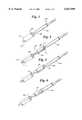
- FIG. 1illustrates a fragmentary side view of a slit tube grasping device having inflatable inner balloons
- FIG. 2is a cross-section projection view of the device of FIG. 1, taken along 2--2;
- FIG. 3illustrates a highly diagrammatic, perspective view of a partially deployed stent, balloon catheter, and guide catheter
- FIG. 4further illustrates the perspective view of FIG. 3, including the stent retrieval device of FIG. 1 before stent capture and before tube profile recovery;
- FIG. 5further illustrates the perspective view of FIG. 3, including the stent retrieval device of FIG. 1 before stent capture after profile recovery;
- FIG. 6further illustrates the perspective view of FIG. 3, including the stent retrieval device of FIG. 1 after stent capture.
- FIG. 1illustrates a stent retrieval device 20 embodying the present invention including a tube portion 46 and a shaft portion 22, tube 46 being attached to a distal region of shaft 22, and having a proximal shoulder 30 decreasing in diameter from tube 46 to shaft 22.
- a preferred embodimentincludes a longitudinal slit 40 running the entire length of tube 46 and through shoulder 30 for side mounting tube 46 over a shaft.
- Tube 46can be mounted over the proximal region of a balloon catheter shaft extending proximally from a guide catheter within the patient.
- tube 46includes radial reinforcing ribs 36 joined to a longitudinal spine 34. In a preferred embodiment, there are three ribs.
- tube 46has a slight taper over its length, having a larger inside diameter distally then proximally. This aids in stent withdrawal by presenting a smaller profile to the guide catheter distal end upon withdrawal while presenting a larger inside diameter to the stent to be captured.
- a preferred method of making ribs 36 and spine 34is to laser cut a piece of NITINOL tubing, for example, 0.063 inch outside diameter tubing having 0.004 inch wall thickness. The laser cutting leaves spine 34 and ribs 36 as a single piece.
- Shaft 22can be fixedly attached to spine 34 at spine stem 52 by soldering, as indicated at 54.
- shaft 22is formed of stainless steel hypotube which includes inflation lumen 24.
- a preferred embodiment of tube 46has a tube interior sheath 44 forming the inner wall of tube 46.
- Sheath 44substantially covers the inside of tube 46 including ribs 36 and spine 34, but not covering slit 40.
- sheath 44is formed by bonding angioplasty balloon material within the interior of tube 46, leaving slit 40 open.
- the most preferred sheath materialis polyolefin or fluoropolymer. The most preferred method of bonding sleeve to ribs utilizes adhesive.
- One embodimenthas a single inner balloon within tube 46.
- the most preferred embodimenthas two inner balloons 38, within tube 46.
- balloon 38is bonded along a side to the interior of sheath 44, holding balloon 38 away from tube center.
- Balloon 38is in fluid communication with inflation lumen 24.
- the preferred embodimentincludes a shoulder collar 32 over shoulder 30, providing a transition from tube 46 to shaft 22.
- shoulder 30is conical shaped.
- shoulder 30has a contour as illustrated in FIG. 1.
- shoulder collar 32is formed from polyolefin or fluoropolymer. Shoulder collar 32 can be formed by wrapping a piece of polymeric material over shoulder 30 and bonding it in place using adhesive.
- a preferred embodimentincludes a distal receiver 42 attached to the distal region of tube 46.
- Distal receiveris preferably tapered, having a larger inside diameter at the distalmost end than at the proximalmost end.
- distal receiver 42is flares as illustrated in FIG. 1.
- Distal receiver 42can be made from the same material as inner sheath 44, and may be formed in one piece with inner sheath 44.
- Distal receiver 42serves to guide and center a stent relative to tube 46 center during stent capture.
- FIG. 2illustrates a cross section taken through the distal portion of tube 46 distal to the distalmost rib 36.
- Ribs 36are shown divided into long rib 60 and short rib 62 by slit 40.
- slit 40is not located directly opposite spine 34.
- slit 40is located 90 degrees relative to spine 34.
- Sheath 44is interior to ribs 36 in the preferred embodiment. Shoulder collar 32 is shown in background in FIG. 2.
- Balloons 38are shown in both deflated state 38a and inflated state 38b in FIG. 2.
- balloons 38are deflated, preferably under a small vacuum.
- balloons 38are pressurized, decreasing the effective inside diameter of the tube, thereby grasping and compressing the captured end of the stent.
- a balloon catheterIn use, when a balloon catheter is positioned in the patient within a guide catheter, having a stent near the balloon, the distal region of a stent retrieval device is side mounted over a proximal region of the catheter shaft laying outside the patient, and compressed to fit within the guide catheter if necessary.
- the grasping device portion of the retrieval deviceis advanced into the patient, distally out of the guide catheter, to the stent.
- the stentis then grasped by inflating the inner balloons, and pulled back into the guide catheter and withdrawn from the patient.
- FIGS. 3-6illustrate the problem and its solution by the present invention.
- the embodiment of FIG. 1is shown for example, in highly diagrammatic form.
- FIG. 3illustrates a guide catheter 100, including a distal end 102, having an inflatable balloon catheter 107 inserted therethrough, including a catheter shaft 110, and balloon 108.
- Stent 104is shown, having slipped proximally from the desired, mid-balloon position. Distal slippage presents a similar problem.
- Stent 104includes a proximal end 106. As shown, withdrawing balloon catheter 107 into guide catheter 100 presents the possibility of guide catheter distal end 102 pushing stent 104 distally off balloon 108. Even in situations where stent 104 has an outer diameter small enough to fit within guide catheter 100, the possibility of guide catheter 100 dislodging stent 104 upon catheter withdrawal remains.
- tube 46is side mounted over catheter shaft 110 using slit 40, and is reduced in cross sectional area by compressing ribs 36, forcing ribs on one side of slit 40 radially inward, curling tube 46, causing short ribs 62 and long ribs 60 to overlap one another near slit 40. Tube 46 is thereby curled around shaft 110. Tube 46 is advanced distally over the balloon catheter shaft by advancing device shaft 22, through the guide catheter, exiting the guide catheter distal end. Upon exiting the guide catheter, tube 46 is free to expand its original, larger, inside diameter.
- ribs 36are made of NITINOL, which allows tube 46 to return to its original diameter when warmed to body temperature.
- FIG. 4illustrates the stent retrieval device embodiment of FIG. 1, distal of guide catheter distal end 102. The device is shown prior to full profile recovery.
- FIG. 5illustrates the stent retrieval device embodiment of FIG. 1, distal of guide catheter distal end 102. The device is shown, having recovered the full profile present prior to insertion into the guide catheter. As illustrated in FIG. 5, the device distal region is sufficiently large enough to contain stent proximal end 106.
- tube 46is advanced until tube distal receiver 42 surrounds stent proximal end 106.
- a slight vacuumis pulled on balloons 38 to increase the effective inside diameter of tube 46.
- Tube 46is further advanced, with distal receiver 42 guiding stent 104 into the center axis of the tube.
- inflation fluid pressureis applied, inflated balloons 38 to position 38b as illustrated in FIG. 2.
- the increased balloon profiledecreases the effective inside diameter available to the stent, thereby grabbing and compressing the stent With the stent firmly grasped as illustrated in FIG. 6, tube 46 is withdrawn proximally toward the guide catheter distal end.
Landscapes
- Health & Medical Sciences (AREA)
- Heart & Thoracic Surgery (AREA)
- Engineering & Computer Science (AREA)
- Biomedical Technology (AREA)
- Life Sciences & Earth Sciences (AREA)
- Veterinary Medicine (AREA)
- Animal Behavior & Ethology (AREA)
- Public Health (AREA)
- General Health & Medical Sciences (AREA)
- Cardiology (AREA)
- Oral & Maxillofacial Surgery (AREA)
- Vascular Medicine (AREA)
- Transplantation (AREA)
- Child & Adolescent Psychology (AREA)
- Biophysics (AREA)
- Pulmonology (AREA)
- Anesthesiology (AREA)
- Hematology (AREA)
- Media Introduction/Drainage Providing Device (AREA)
Abstract
Description
This application claims the benefit of U.S. Provisional application Ser. No. 60/028,054, filed Oct. 3, 1996.
The present invention relates generally to a method and device for stent retrieval.
Background of the Invention Stents are increasingly used in Percutaneous Transluminal Coronary Angioplasty (PTCA). PTCA is a well established procedure for dilating stenosed vessel regions in the heart. In this procedure, a balloon angioplasty catheter is introduced into the vasculature, typically though an incision in the femoral artery in the groin. The balloon catheter is advanced through the femoral artery, through the aortic arch, and into the artery to be treated. The balloon is advanced across a lesion and inflated, dilating the vessel at the location of the balloon expansion. The dilation increases the vessel cross sectional area and the resultant blood flow.
Over a period of time, the dilated vessel section may narrow again, in part due to a rebound from the angioplasty procedure, thereby reversing some of the benefits of the angioplasty. To prevent this vessel narrowing, stents are increasingly used. Stents are placed across the dilated region and radially expanded, opposing any inward radial force by the vessel walls.
Stents may be categorized as self-expanding and balloon expanding. The self-expanding stents are contained within a sheath to prevent premature expansion. The stent is placed within a guide catheter, moved across a lesion, withdrawn from the sheath, and the stent, being biased to expand, expands, ideally with sufficient force to resist the vessel wall rebound force which can occur after angioplasty. The stent can be left in place indefinitely.
Balloon-expandable stent deployment requires "tacking up" the stent, forcing stent struts or members radially outward into close proximity with the vessel wall. The stent is mounted over an uninflated balloon, crimped, and the balloon with stent advanced within a guide catheter. The balloon with stent is advanced distally out of the guide catheter across the lesion. The balloon is inflated, expanding the stent, thereby tacking the stent in place. For optimal stent placement, it is necessary for the stent to be properly positioned axially on the balloon prior to balloon inflation. A non-compliant balloon operated at high pressure is typically used to expand the inside diameter of the stent, forcing it against the vessel interior walls. The balloon is deflated, and withdrawn proximally into the guide catheter.
For both types of stents, self-expanding and balloon expandable, a sheath can be used during stent delivery, being interposed between stent and guide catheter. The sheath adds a not-insubstantial thickness around the stent, increasing the vessel inside diameter required to pass the sheathed stent. In one case, when using a sheath, a sheath outside diameter of 72 mils (thousands of an inch) is required to place a stent having an outside diameter of 60 mils. When not using a sheath, clearance is only required for the 60 mil sheath. This reduced outer diameter translates into increased vasculature accessible for stent placement, making treatable otherwise untreatable lesions.
As a result of the increased vasculature reachable without sheaths, treating physicians increasingly prefer to place stents without using a sheath, the "bare mounted" technique. This is possible with balloon-expanding stents, but has associated difficulties. A stent can be bare mounted over a balloon, crimped, and the balloon advanced through the guide catheter to the distal region of the guide catheter, which is positioned proximal to the vessel region having a lesion. The balloon with stent is advanced distally out of the guide catheter and across the lesion. When the stent is crimped onto the balloon, there can be a slight recoil, such that when balloon and stent are advanced out of the guide catheter, the stent is too large to be retracted into the guide catheter even before balloon inflation.
Occasionally, there are situations where the stent becomes partially or totally dislodged from the balloon. The dislodged stent may be detected while still within the guide catheter. A dislodged stent can be detected using radiography, observing relative positions of radiopaque regions on the stent and balloon catheter. When the stent is dislodged while within the guide catheter, it may be possible to withdraw the balloon catheter and stent together.
At other times, the stent becomes dislodged after the stent has been advanced out of the guide catheter. As the balloon-expanding stents do not self-expand, this creates the situation where a stent may become loose in the vasculature. When the stent is only partially dislodged from the balloon, the balloon with partially mounted stent may be withdrawn proximally into the guide catheter. The stent outer diameter is often only slightly less than the inner diameter of the guide catheter, to keep the guide catheter size down and increase the amount of vasculature open to the guide catheter. The stent outer diameter may be larger than the guide catheter inner diameter, and withdrawal of the balloon will not withdraw the stent, but may instead force the stent off the balloon.
In cases where the stent remains sufficiently small to fit within the guide catheter, withdrawal may still prove problematic. During attempted recovery, there is a point at which the proximal edge of the stent is to be withdrawn proximally past the distal edge of the guide catheter. If the stent is not centered relative to the longitudinal axis of the guide catheter, the guide catheter distal edge may catch against the stent proximal edge, forcing the stent from the balloon.
What would be desirable is a device for retrieving a partially deployed stent. A device for grasping, compressing, and retracting a stent has not hereto been provided.
The present invention provides a device and method for retrieving stents from within a body conduit such as a vein or artery. While the preferred use of the invention is to retrieve coronary stents, use in retrieving stents from other body conduits is contemplated and is explicitly within the scope of the invention.
This can be accomplished by side mounting a stent retriever tube having inner inflatable balloons over the proximal end of a balloon catheter shaft, compressing the tube thereby decreasing the profile, advancing the tube through the guide catheter to the stent, allowing the tube to recover its full profile, pulling a slight vacuum on the inner balloons, advancing the tube over the stent, inflating the inner balloons, grasping the stent, and withdrawing the stent into the guide catheter. While the preferred embodiment mounts over a balloon catheter shaft, the invention may be mounted over other shafts, including guide wires, and may be used without any shaft at all. The preferred embodiment is advanced within a guide catheter, but advancement within other elongate tubes is contemplated and is also within the scope of the invention.
In one embodiment, the retrieval device includes an elongate shaft having a longitudinally slit tube mounted at the distal end. The preferred tube includes a metal (e.g., stainless steel, super-elastic alloy) spine and rib cage having a polymeric sheath bonded to the interior, exclusive of the slit. The tube further includes at least one inflatable inner balloon, attached near the interior wall of the tube. The preferred embodiment has two or more inflatable balloons. The shaft preferably includes hypotube in fluid communication with the inflatable balloons. While tubular shaped balloons are preferred, running substantially the length of the tube, other sized balloons, including a concentric, double walled, inflatable sleeve, is contemplated for use as the balloon. The transition from tube to shaft includes a shoulder, preferably formed of polymeric material. When inflation fluid is supplied to the inflatable balloons, the balloons increase in diameter, decreasing the effective inside diameter of the tube, grasping and compressing any stent within the tube, enabling the capture and withdrawal of a stent.
In use, the slit tube is mounted over a shaft lying within a guide catheter, such as a stent placement balloon shaft. The tube is compressed by curling one side of ribs inside the other side of ribs near the tube slit. The tube is advanced through the guide catheter, exiting the guide catheter distally, and allowed to recover its original profile. The tube is advanced over the stent, and inflation fluid is supplied to inner balloons, decreasing the effective inside diameter, grasping and compressing the stent. The tube grasping the stent is then withdrawn into and through the guide catheter and out of the patient.
FIG. 1 illustrates a fragmentary side view of a slit tube grasping device having inflatable inner balloons;
FIG. 2 is a cross-section projection view of the device of FIG. 1, taken along 2--2;
FIG. 3 illustrates a highly diagrammatic, perspective view of a partially deployed stent, balloon catheter, and guide catheter;
FIG. 4 further illustrates the perspective view of FIG. 3, including the stent retrieval device of FIG. 1 before stent capture and before tube profile recovery;
FIG. 5 further illustrates the perspective view of FIG. 3, including the stent retrieval device of FIG. 1 before stent capture after profile recovery; and
FIG. 6 further illustrates the perspective view of FIG. 3, including the stent retrieval device of FIG. 1 after stent capture.
FIG. 1 illustrates astent retrieval device 20 embodying the present invention including atube portion 46 and ashaft portion 22,tube 46 being attached to a distal region ofshaft 22, and having aproximal shoulder 30 decreasing in diameter fromtube 46 toshaft 22. A preferred embodiment includes alongitudinal slit 40 running the entire length oftube 46 and throughshoulder 30 forside mounting tube 46 over a shaft.Tube 46 can be mounted over the proximal region of a balloon catheter shaft extending proximally from a guide catheter within the patient. In a preferred embodiment,tube 46 includes radial reinforcing ribs 36 joined to a longitudinal spine 34. In a preferred embodiment, there are three ribs.
In one embodiment,tube 46 has a slight taper over its length, having a larger inside diameter distally then proximally. This aids in stent withdrawal by presenting a smaller profile to the guide catheter distal end upon withdrawal while presenting a larger inside diameter to the stent to be captured.
A preferred method of making ribs 36 and spine 34 is to laser cut a piece of NITINOL tubing, for example, 0.063 inch outside diameter tubing having 0.004 inch wall thickness. The laser cutting leaves spine 34 and ribs 36 as a single piece.
A preferred embodiment oftube 46 has a tube interior sheath 44 forming the inner wall oftube 46. Sheath 44 substantially covers the inside oftube 46 including ribs 36 and spine 34, but not coveringslit 40. In a preferred embodiment, sheath 44 is formed by bonding angioplasty balloon material within the interior oftube 46, leaving slit 40 open. The most preferred sheath material is polyolefin or fluoropolymer. The most preferred method of bonding sleeve to ribs utilizes adhesive.
One embodiment has a single inner balloon withintube 46. The most preferred embodiment has two inner balloons 38, withintube 46. In the most preferred embodiment, balloon 38 is bonded along a side to the interior of sheath 44, holding balloon 38 away from tube center. Balloon 38 is in fluid communication with inflation lumen 24.
The preferred embodiment includes a shoulder collar 32 overshoulder 30, providing a transition fromtube 46 toshaft 22. In one embodiment,shoulder 30 is conical shaped. In a most preferred embodiment,shoulder 30 has a contour as illustrated in FIG. 1. In a preferred embodiment, shoulder collar 32 is formed from polyolefin or fluoropolymer. Shoulder collar 32 can be formed by wrapping a piece of polymeric material overshoulder 30 and bonding it in place using adhesive.
A preferred embodiment includes adistal receiver 42 attached to the distal region oftube 46. Distal receiver is preferably tapered, having a larger inside diameter at the distalmost end than at the proximalmost end. In the preferred embodiment,distal receiver 42 is flares as illustrated in FIG. 1.Distal receiver 42 can be made from the same material as inner sheath 44, and may be formed in one piece with inner sheath 44.Distal receiver 42 serves to guide and center a stent relative totube 46 center during stent capture.
FIG. 2 illustrates a cross section taken through the distal portion oftube 46 distal to the distalmost rib 36. Ribs 36 are shown divided intolong rib 60 and short rib 62 byslit 40. In a preferred embodiment, slit 40 is not located directly opposite spine 34. In a most preferred embodiment, slit 40 is located 90 degrees relative to spine 34. Sheath 44 is interior to ribs 36 in the preferred embodiment. Shoulder collar 32 is shown in background in FIG. 2.
Balloons 38 are shown in both deflated state 38a and inflated state 38b in FIG. 2. Whentube 46 is advanced toward the stent, balloons 38 are deflated, preferably under a small vacuum. Whentube 46 has advanced over the stent to be captured, balloons 38 are pressurized, decreasing the effective inside diameter of the tube, thereby grasping and compressing the captured end of the stent.
In use, when a balloon catheter is positioned in the patient within a guide catheter, having a stent near the balloon, the distal region of a stent retrieval device is side mounted over a proximal region of the catheter shaft laying outside the patient, and compressed to fit within the guide catheter if necessary. The grasping device portion of the retrieval device is advanced into the patient, distally out of the guide catheter, to the stent. The stent is then grasped by inflating the inner balloons, and pulled back into the guide catheter and withdrawn from the patient.
FIGS. 3-6 illustrate the problem and its solution by the present invention. The embodiment of FIG. 1 is shown for example, in highly diagrammatic form.
FIG. 3 illustrates aguide catheter 100, including adistal end 102, having aninflatable balloon catheter 107 inserted therethrough, including acatheter shaft 110, and balloon 108.Stent 104 is shown, having slipped proximally from the desired, mid-balloon position. Distal slippage presents a similar problem.Stent 104 includes aproximal end 106. As shown, withdrawingballoon catheter 107 intoguide catheter 100 presents the possibility of guide catheterdistal end 102 pushingstent 104 distally off balloon 108. Even in situations wherestent 104 has an outer diameter small enough to fit withinguide catheter 100, the possibility ofguide catheter 100 dislodgingstent 104 upon catheter withdrawal remains. This possibility exists ifdevice catheter shaft 22 is not sufficiently centered withinguide catheter 100, thereby allowing stent to be withdrawn proximally while off-center. Such an off-center withdrawal can allowstent 104 to be pushed distally by part of guide catheterdistal end 102.
In the preferred method of stent retrieval,tube 46 is side mounted overcatheter shaft 110 usingslit 40, and is reduced in cross sectional area by compressing ribs 36, forcing ribs on one side ofslit 40 radially inward, curlingtube 46, causing short ribs 62 andlong ribs 60 to overlap one anothernear slit 40.Tube 46 is thereby curled aroundshaft 110.Tube 46 is advanced distally over the balloon catheter shaft by advancingdevice shaft 22, through the guide catheter, exiting the guide catheter distal end. Upon exiting the guide catheter,tube 46 is free to expand its original, larger, inside diameter. In a preferred embodiment, ribs 36 are made of NITINOL, which allowstube 46 to return to its original diameter when warmed to body temperature.
FIG. 4 illustrates the stent retrieval device embodiment of FIG. 1, distal of guide catheterdistal end 102. The device is shown prior to full profile recovery. FIG. 5 illustrates the stent retrieval device embodiment of FIG. 1, distal of guide catheterdistal end 102. The device is shown, having recovered the full profile present prior to insertion into the guide catheter. As illustrated in FIG. 5, the device distal region is sufficiently large enough to contain stentproximal end 106.
With the aid of radiographic visualization,tube 46 is advanced until tubedistal receiver 42 surrounds stentproximal end 106. In the preferred method, a slight vacuum is pulled on balloons 38 to increase the effective inside diameter oftube 46.Tube 46 is further advanced, withdistal receiver 42 guidingstent 104 into the center axis of the tube. With the stent at least partially withintube 46, inflation fluid pressure is applied, inflated balloons 38 to position 38b as illustrated in FIG. 2. The increased balloon profile decreases the effective inside diameter available to the stent, thereby grabbing and compressing the stent With the stent firmly grasped as illustrated in FIG. 6,tube 46 is withdrawn proximally toward the guide catheter distal end.Shoulder 30 is drawn first into the guide catheter, centeringtube 46 within the guide catheter and presenting a smooth contour for withdrawal. Asdevice shaft 22 is stronger in tension than compression, a larger profile fortube 46 and a larger amount of friction is more tolerable during device withdrawal than device advancement.Tube 46 is further withdrawn, exiting the patient's body and the guide catheter.
Numerous characteristics and advantages of the invention covered by this document have been set forth in the foregoing description. It will be understood, however, that this disclosure is, in many respects, only illustrative. Changes may be made in details, particularly in matters of shape, size, and arrangement of parts without exceeding the scope of the invention. The inventions's scope is, of course, defined in the language in which the appended claims are expressed.
Claims (8)
1. A stent retrieval device comprising:
an elongate shaft having an inflation lumen and a distal region;
a tube, said tube operatively attached to said shaft distal region, wherein said tube includes a proximal shoulder extending proximally from said tube proximal region to said shaft, decreasing proximally in outer diameter and wherein said tube includes a longitudinal slit; and
an inflatable balloon within said tube, said balloon being in fluid communication with said shaft inflation lumen.
2. A stent retrieval device as recited in claim 1, wherein said slit is substantially linear.
3. A stent retrieval device as recited in claim 2, wherein said tube includes a plurality of reinforcing ribs.
4. A stent retrieval device as recited in claim 3, wherein said tube includes a distal region, said device further comprising
a distal receiver, said receiver operatively attached to said tube distal region and tapered, having a distalmost inside diameter greater than a proximalmost inside diameter.
5. A method for retrieving a stent comprising:
providing a stent retrieval device including an elongate shaft having a distal region, a retrieval tube operatively attached to said shaft distal region, said retrieval tube having at least one inflatable balloon attached within said tube interior, said retrieval tube decreasing in effective inside diameter when said balloon is inflated;
inserting an elongate tube intravascularly into a patient, a portion of said elongate tube extending proximally therefrom, a stent being positioned near the distal end of said elongate tube;
advancing said retrieval tube distally into said patient;
advancing said retrieval tube distal end toward said elongate tube distal end;
advancing said retrieval tube distal end until a portion of said stent proximal end is within said retrieval tube distal end,
decreasing said retrieval tube effective inside diameter;
retracting said retrieval tube containing said stent proximally.
6. A method as recited in claim 5, wherein said elongate tube is a guide catheter.
7. A method as recited in claim 6, wherein said guide catheter has a balloon catheter inserted therethrough, further comprising selecting a section of balloon catheter shaft proximal to said patient's body and moving said retrieval tube over said catheter shaft.
8. A method as recited in claim 7, wherein said retrieval tube has a longitudinal slit therethrough, further comprising selecting a section of balloon catheter shaft proximal to said patient's body and moving said retrieval tube slit over said catheter shaft.
Priority Applications (1)
| Application Number | Priority Date | Filing Date | Title |
|---|---|---|---|
| US08/942,432US6027509A (en) | 1996-10-03 | 1997-10-01 | Stent retrieval device |
Applications Claiming Priority (2)
| Application Number | Priority Date | Filing Date | Title |
|---|---|---|---|
| US2805496P | 1996-10-03 | 1996-10-03 | |
| US08/942,432US6027509A (en) | 1996-10-03 | 1997-10-01 | Stent retrieval device |
Publications (1)
| Publication Number | Publication Date |
|---|---|
| US6027509Atrue US6027509A (en) | 2000-02-22 |
Family
ID=26703222
Family Applications (1)
| Application Number | Title | Priority Date | Filing Date |
|---|---|---|---|
| US08/942,432Expired - LifetimeUS6027509A (en) | 1996-10-03 | 1997-10-01 | Stent retrieval device |
Country Status (1)
| Country | Link |
|---|---|
| US (1) | US6027509A (en) |
Cited By (33)
| Publication number | Priority date | Publication date | Assignee | Title |
|---|---|---|---|---|
| US6187016B1 (en)* | 1999-09-14 | 2001-02-13 | Daniel G. Hedges | Stent retrieval device |
| US20020107541A1 (en)* | 1999-05-07 | 2002-08-08 | Salviac Limited. | Filter element for embolic protection device |
| US20030009189A1 (en)* | 1997-11-07 | 2003-01-09 | Salviac Limited | Embolic protection device |
| US20030032977A1 (en)* | 1997-11-07 | 2003-02-13 | Salviac Limited | Filter element with retractable guidewire tip |
| WO2003073962A1 (en)* | 2002-03-05 | 2003-09-12 | Salviac Limited | An embolic protection system |
| US6636758B2 (en) | 2001-05-01 | 2003-10-21 | Concentric Medical, Inc. | Marker wire and process for using it |
| US6638245B2 (en) | 2001-06-26 | 2003-10-28 | Concentric Medical, Inc. | Balloon catheter |
| WO2003094789A1 (en)* | 2002-05-13 | 2003-11-20 | Salviac Limited | Retrieval catheter for an embolic filter |
| US6702782B2 (en) | 2001-06-26 | 2004-03-09 | Concentric Medical, Inc. | Large lumen balloon catheter |
| WO2004039290A1 (en) | 2002-11-01 | 2004-05-13 | Mirza Kamran Baig | Retrieval device |
| US6802846B2 (en) | 2001-02-12 | 2004-10-12 | Ams Research Corporation | Foreign body retrieval device and method |
| US20040204737A1 (en)* | 2003-04-11 | 2004-10-14 | Scimed Life Systems, Inc. | Embolic filter loop fabricated from composite material |
| US20050228437A1 (en)* | 1997-11-07 | 2005-10-13 | Salviac Limited | Embolic protection system |
| US20050267523A1 (en)* | 2004-03-03 | 2005-12-01 | Nmt Medical Inc. | Delivery/recovery system for septal occluder |
| US20050267555A1 (en)* | 2004-05-28 | 2005-12-01 | Marnfeldt Goran N | Engagement tool for implantable medical devices |
| US20050273119A1 (en)* | 2003-12-09 | 2005-12-08 | Nmt Medical, Inc. | Double spiral patent foramen ovale closure clamp |
| US20050275544A1 (en)* | 2004-05-04 | 2005-12-15 | R.W. Breakpoint L.L.C. | System and method for elimination of bedwetting behavior |
| US7063707B2 (en) | 2002-03-06 | 2006-06-20 | Scimed Life Systems, Inc. | Medical retrieval device |
| US7115141B2 (en)* | 2000-10-09 | 2006-10-03 | Universitatsklinikum Freiburg | Device for supporting a surgical step in a vessel, particularly for removal and implantation of heart valves |
| US20070168014A1 (en)* | 2006-01-13 | 2007-07-19 | Jimenez Teodoro S | Stent Delivery System |
| US20080051870A1 (en)* | 2006-07-19 | 2008-02-28 | Ralf Kaufmann | Marker element for the precise implantation of stents |
| US20080167677A1 (en)* | 1999-05-07 | 2008-07-10 | Salviac Limited | Filter element for embolic protection device |
| WO2008124618A1 (en)* | 2007-04-05 | 2008-10-16 | Nmt Medical, Inc. | Implant recovery device |
| US20100094399A1 (en)* | 2001-04-30 | 2010-04-15 | C. R. Bard, Inc. | Variable speed self-expanding stent delivery system and luer locking connector |
| US20100168756A1 (en)* | 2006-08-07 | 2010-07-01 | Dorn Juergen | Hand-held actuator device |
| US20100174290A1 (en)* | 2007-07-11 | 2010-07-08 | C.R. Bard, Inc. | Device for catheter sheath retraction |
| US20110054396A1 (en)* | 2009-08-27 | 2011-03-03 | Boston Scientific Scimed, Inc. | Balloon Catheter Devices With Drug-Coated Sheath |
| US7935141B2 (en) | 2005-08-17 | 2011-05-03 | C. R. Bard, Inc. | Variable speed stent delivery system |
| US8034095B2 (en) | 2008-08-29 | 2011-10-11 | Cook Medical Technologies Llc | Intraluminal system for retrieving an implantable medical device |
| US9138562B2 (en) | 2007-04-18 | 2015-09-22 | W.L. Gore & Associates, Inc. | Flexible catheter system |
| US9801745B2 (en) | 2010-10-21 | 2017-10-31 | C.R. Bard, Inc. | System to deliver a bodily implant |
| US11006939B2 (en) | 2017-12-08 | 2021-05-18 | Tendyne Holdings, Inc. | Introducer sheath with seal and methods of using the same |
| US11026822B2 (en) | 2006-01-13 | 2021-06-08 | C. R. Bard, Inc. | Stent delivery system |
Citations (39)
| Publication number | Priority date | Publication date | Assignee | Title |
|---|---|---|---|---|
| US2944552A (en)* | 1958-12-29 | 1960-07-12 | Richard B Wilk | Surgical instrument |
| US3421509A (en)* | 1965-12-17 | 1969-01-14 | John M Fiore | Urethral catheter |
| US3657744A (en)* | 1970-05-08 | 1972-04-25 | Univ Minnesota | Method for fixing prosthetic implants in a living body |
| DE2104673A1 (en)* | 1970-11-24 | 1972-05-31 | VEB Kombinat Medizin- und Labortechnik, χ 7035 Leipzig | Device for the removal of ureteral stones and stones in the lower renal pelvis |
| US3842441A (en)* | 1972-10-12 | 1974-10-22 | A Kaiser | A temporary implant and method for tendon surgery |
| US3993078A (en)* | 1974-11-04 | 1976-11-23 | Gambro Ag | Insert for use preferably in vascular surgery |
| US4130904A (en)* | 1977-06-06 | 1978-12-26 | Thermo Electron Corporation | Prosthetic blood conduit |
| US4140126A (en)* | 1977-02-18 | 1979-02-20 | Choudhury M Hasan | Method for performing aneurysm repair |
| US4313231A (en)* | 1980-06-16 | 1982-02-02 | Kabushiki Kaisha Tatebe Seishudo | Vascular prosthesis |
| US4315509A (en)* | 1977-01-10 | 1982-02-16 | Smit Julie A | Insertion and removal catheters and intestinal tubes for restricting absorption |
| US4434797A (en)* | 1979-01-12 | 1984-03-06 | Ab Tesi | Catheter |
| US4483339A (en)* | 1982-01-29 | 1984-11-20 | Rolando Gillis | Vascular surgery roll |
| US4512338A (en)* | 1983-01-25 | 1985-04-23 | Balko Alexander B | Process for restoring patency to body vessels |
| US4562596A (en)* | 1984-04-25 | 1986-01-07 | Elliot Kornberg | Aortic graft, device and method for performing an intraluminal abdominal aortic aneurysm repair |
| US4594996A (en)* | 1982-09-30 | 1986-06-17 | Ibrahim Adel A | Method for removing objects from tubular body passages |
| US4732152A (en)* | 1984-12-05 | 1988-03-22 | Medinvent S.A. | Device for implantation and a method of implantation in a vessel using such device |
| US4733665A (en)* | 1985-11-07 | 1988-03-29 | Expandable Grafts Partnership | Expandable intraluminal graft, and method and apparatus for implanting an expandable intraluminal graft |
| US4744366A (en)* | 1986-09-10 | 1988-05-17 | Jang G David | Concentric independently inflatable/deflatable multiple diameter balloon angioplasty catheter systems and method of use |
| EP0274846A1 (en)* | 1986-12-09 | 1988-07-20 | Boston Scientific Corporation | Apparatus for treating hypertrophy of the prostate gland |
| US4793348A (en)* | 1986-11-15 | 1988-12-27 | Palmaz Julio C | Balloon expandable vena cava filter to prevent migration of lower extremity venous clots into the pulmonary circulation |
| US4800882A (en)* | 1987-03-13 | 1989-01-31 | Cook Incorporated | Endovascular stent and delivery system |
| US4886062A (en)* | 1987-10-19 | 1989-12-12 | Medtronic, Inc. | Intravascular radially expandable stent and method of implant |
| US4907336A (en)* | 1987-03-13 | 1990-03-13 | Cook Incorporated | Method of making an endovascular stent and delivery system |
| US4913141A (en)* | 1988-10-25 | 1990-04-03 | Cordis Corporation | Apparatus and method for placement of a stent within a subject vessel |
| US4921478A (en)* | 1988-02-23 | 1990-05-01 | C. R. Bard, Inc. | Cerebral balloon angioplasty system |
| US4932959A (en)* | 1988-12-01 | 1990-06-12 | Advanced Cardiovascular Systems, Inc. | Vascular catheter with releasably secured guidewire |
| US5026377A (en)* | 1989-07-13 | 1991-06-25 | American Medical Systems, Inc. | Stent placement instrument and method |
| US5053013A (en)* | 1990-03-01 | 1991-10-01 | The Regents Of The University Of Michigan | Implantable infusion device |
| US5156596A (en)* | 1991-02-04 | 1992-10-20 | Menlo Care, Inc. | Catheter with changeable number of lumens |
| US5275605A (en)* | 1992-01-08 | 1994-01-04 | Klaus Winkler | Apparatus for removing calculi from animal bodies |
| US5330482A (en)* | 1991-06-17 | 1994-07-19 | Wilson-Cook Medical Inc. | Endoscopic extraction devices, wire basket stone extractors, stent retrievers, snares and method of constructing the same |
| US5334208A (en)* | 1990-07-09 | 1994-08-02 | Wilson-Cook Medical Inc. | Method for retrieving stents |
| US5388590A (en)* | 1993-07-28 | 1995-02-14 | Medtronic, Inc. | Catheter exchange device |
| US5409495A (en)* | 1993-08-24 | 1995-04-25 | Advanced Cardiovascular Systems, Inc. | Apparatus for uniformly implanting a stent |
| US5411507A (en)* | 1993-01-08 | 1995-05-02 | Richard Wolf Gmbh | Instrument for implanting and extracting stents |
| US5474563A (en)* | 1993-03-25 | 1995-12-12 | Myler; Richard | Cardiovascular stent and retrieval apparatus |
| US5520697A (en)* | 1992-06-20 | 1996-05-28 | Angiomed Ag | Apparatus for correcting the position of a stent |
| US5628754A (en)* | 1995-08-01 | 1997-05-13 | Medtronic, Inc. | Stent delivery guide catheter |
| US5634937A (en)* | 1995-05-19 | 1997-06-03 | General Surgical Innovations, Inc. | Skin seal with inflatable membrane |
- 1997
- 1997-10-01USUS08/942,432patent/US6027509A/ennot_activeExpired - Lifetime
Patent Citations (45)
| Publication number | Priority date | Publication date | Assignee | Title |
|---|---|---|---|---|
| US2944552A (en)* | 1958-12-29 | 1960-07-12 | Richard B Wilk | Surgical instrument |
| US3421509A (en)* | 1965-12-17 | 1969-01-14 | John M Fiore | Urethral catheter |
| US3657744A (en)* | 1970-05-08 | 1972-04-25 | Univ Minnesota | Method for fixing prosthetic implants in a living body |
| DE2104673A1 (en)* | 1970-11-24 | 1972-05-31 | VEB Kombinat Medizin- und Labortechnik, χ 7035 Leipzig | Device for the removal of ureteral stones and stones in the lower renal pelvis |
| US3842441A (en)* | 1972-10-12 | 1974-10-22 | A Kaiser | A temporary implant and method for tendon surgery |
| US3993078A (en)* | 1974-11-04 | 1976-11-23 | Gambro Ag | Insert for use preferably in vascular surgery |
| US4315509A (en)* | 1977-01-10 | 1982-02-16 | Smit Julie A | Insertion and removal catheters and intestinal tubes for restricting absorption |
| US4140126A (en)* | 1977-02-18 | 1979-02-20 | Choudhury M Hasan | Method for performing aneurysm repair |
| US4130904A (en)* | 1977-06-06 | 1978-12-26 | Thermo Electron Corporation | Prosthetic blood conduit |
| US4434797A (en)* | 1979-01-12 | 1984-03-06 | Ab Tesi | Catheter |
| US4313231A (en)* | 1980-06-16 | 1982-02-02 | Kabushiki Kaisha Tatebe Seishudo | Vascular prosthesis |
| US4483339A (en)* | 1982-01-29 | 1984-11-20 | Rolando Gillis | Vascular surgery roll |
| US4594996A (en)* | 1982-09-30 | 1986-06-17 | Ibrahim Adel A | Method for removing objects from tubular body passages |
| US4512338A (en)* | 1983-01-25 | 1985-04-23 | Balko Alexander B | Process for restoring patency to body vessels |
| US4562596A (en)* | 1984-04-25 | 1986-01-07 | Elliot Kornberg | Aortic graft, device and method for performing an intraluminal abdominal aortic aneurysm repair |
| US4732152A (en)* | 1984-12-05 | 1988-03-22 | Medinvent S.A. | Device for implantation and a method of implantation in a vessel using such device |
| US4733665A (en)* | 1985-11-07 | 1988-03-29 | Expandable Grafts Partnership | Expandable intraluminal graft, and method and apparatus for implanting an expandable intraluminal graft |
| US4739762A (en)* | 1985-11-07 | 1988-04-26 | Expandable Grafts Partnership | Expandable intraluminal graft, and method and apparatus for implanting an expandable intraluminal graft |
| US4776337A (en)* | 1985-11-07 | 1988-10-11 | Expandable Grafts Partnership | Expandable intraluminal graft, and method and apparatus for implanting an expandable intraluminal graft |
| US4733665B1 (en)* | 1985-11-07 | 1994-01-11 | Expandable Grafts Partnership | Expandable intraluminal graft,and method and apparatus for implanting an expandable intraluminal graft |
| US4733665C2 (en)* | 1985-11-07 | 2002-01-29 | Expandable Grafts Partnership | Expandable intraluminal graft and method and apparatus for implanting an expandable intraluminal graft |
| US4776337B1 (en)* | 1985-11-07 | 2000-12-05 | Cordis Corp | Expandable intraluminal graft and method and apparatus for implanting an expandable intraluminal graft |
| US4739762B1 (en)* | 1985-11-07 | 1998-10-27 | Expandable Grafts Partnership | Expandable intraluminal graft and method and apparatus for implanting an expandable intraluminal graft |
| US4744366A (en)* | 1986-09-10 | 1988-05-17 | Jang G David | Concentric independently inflatable/deflatable multiple diameter balloon angioplasty catheter systems and method of use |
| US4793348A (en)* | 1986-11-15 | 1988-12-27 | Palmaz Julio C | Balloon expandable vena cava filter to prevent migration of lower extremity venous clots into the pulmonary circulation |
| EP0274846A1 (en)* | 1986-12-09 | 1988-07-20 | Boston Scientific Corporation | Apparatus for treating hypertrophy of the prostate gland |
| US4800882A (en)* | 1987-03-13 | 1989-01-31 | Cook Incorporated | Endovascular stent and delivery system |
| US4907336A (en)* | 1987-03-13 | 1990-03-13 | Cook Incorporated | Method of making an endovascular stent and delivery system |
| US4886062A (en)* | 1987-10-19 | 1989-12-12 | Medtronic, Inc. | Intravascular radially expandable stent and method of implant |
| US4921478A (en)* | 1988-02-23 | 1990-05-01 | C. R. Bard, Inc. | Cerebral balloon angioplasty system |
| US4913141A (en)* | 1988-10-25 | 1990-04-03 | Cordis Corporation | Apparatus and method for placement of a stent within a subject vessel |
| US4932959A (en)* | 1988-12-01 | 1990-06-12 | Advanced Cardiovascular Systems, Inc. | Vascular catheter with releasably secured guidewire |
| US5026377A (en)* | 1989-07-13 | 1991-06-25 | American Medical Systems, Inc. | Stent placement instrument and method |
| US5053013A (en)* | 1990-03-01 | 1991-10-01 | The Regents Of The University Of Michigan | Implantable infusion device |
| US5334208A (en)* | 1990-07-09 | 1994-08-02 | Wilson-Cook Medical Inc. | Method for retrieving stents |
| US5156596A (en)* | 1991-02-04 | 1992-10-20 | Menlo Care, Inc. | Catheter with changeable number of lumens |
| US5330482A (en)* | 1991-06-17 | 1994-07-19 | Wilson-Cook Medical Inc. | Endoscopic extraction devices, wire basket stone extractors, stent retrievers, snares and method of constructing the same |
| US5275605A (en)* | 1992-01-08 | 1994-01-04 | Klaus Winkler | Apparatus for removing calculi from animal bodies |
| US5520697A (en)* | 1992-06-20 | 1996-05-28 | Angiomed Ag | Apparatus for correcting the position of a stent |
| US5411507A (en)* | 1993-01-08 | 1995-05-02 | Richard Wolf Gmbh | Instrument for implanting and extracting stents |
| US5474563A (en)* | 1993-03-25 | 1995-12-12 | Myler; Richard | Cardiovascular stent and retrieval apparatus |
| US5388590A (en)* | 1993-07-28 | 1995-02-14 | Medtronic, Inc. | Catheter exchange device |
| US5409495A (en)* | 1993-08-24 | 1995-04-25 | Advanced Cardiovascular Systems, Inc. | Apparatus for uniformly implanting a stent |
| US5634937A (en)* | 1995-05-19 | 1997-06-03 | General Surgical Innovations, Inc. | Skin seal with inflatable membrane |
| US5628754A (en)* | 1995-08-01 | 1997-05-13 | Medtronic, Inc. | Stent delivery guide catheter |
Cited By (109)
| Publication number | Priority date | Publication date | Assignee | Title |
|---|---|---|---|---|
| US20090099593A1 (en)* | 1997-11-07 | 2009-04-16 | Salviac Limited | Embolic protection device |
| US20060129182A1 (en)* | 1997-11-07 | 2006-06-15 | Salviac Limited | Embolic protection device |
| US20030009189A1 (en)* | 1997-11-07 | 2003-01-09 | Salviac Limited | Embolic protection device |
| US20030032977A1 (en)* | 1997-11-07 | 2003-02-13 | Salviac Limited | Filter element with retractable guidewire tip |
| US8852226B2 (en) | 1997-11-07 | 2014-10-07 | Salviac Limited | Vascular device for use during an interventional procedure |
| US8603131B2 (en) | 1997-11-07 | 2013-12-10 | Salviac Limited | Embolic protection device |
| US20090143814A1 (en)* | 1997-11-07 | 2009-06-04 | Salviac Limited | Embolic protection device |
| US20030208228A1 (en)* | 1997-11-07 | 2003-11-06 | Paul Gilson | Embolic protection device |
| US8430901B2 (en) | 1997-11-07 | 2013-04-30 | Salviac Limited | Embolic protection device |
| US8328842B2 (en) | 1997-11-07 | 2012-12-11 | Salviac Limited | Filter element with retractable guidewire tip |
| US8241319B2 (en) | 1997-11-07 | 2012-08-14 | Salviac Limited | Embolic protection system |
| US20040034385A1 (en)* | 1997-11-07 | 2004-02-19 | Paul Gilson | Embolic protection device |
| US8226678B2 (en) | 1997-11-07 | 2012-07-24 | Salviac Limited | Embolic protection device |
| US7491216B2 (en) | 1997-11-07 | 2009-02-17 | Salviac Limited | Filter element with retractable guidewire tip |
| US8221448B2 (en) | 1997-11-07 | 2012-07-17 | Salviac Limited | Embolic protection device |
| US8216270B2 (en) | 1997-11-07 | 2012-07-10 | Salviac Limited | Embolic protection device |
| US8057504B2 (en) | 1997-11-07 | 2011-11-15 | Salviac Limited | Embolic protection device |
| US20050228437A1 (en)* | 1997-11-07 | 2005-10-13 | Salviac Limited | Embolic protection system |
| US20050234502A1 (en)* | 1997-11-07 | 2005-10-20 | Paul Gilson | Embolic protection system |
| US8052716B2 (en) | 1997-11-07 | 2011-11-08 | Salviac Limited | Embolic protection system |
| US7972352B2 (en) | 1997-11-07 | 2011-07-05 | Salviac Limited | Embolic protection system |
| US20110125182A1 (en)* | 1997-11-07 | 2011-05-26 | Salviac Limited | Filter element with retractable guidewire tip |
| US7901426B2 (en) | 1997-11-07 | 2011-03-08 | Salviac Limited | Embolic protection device |
| US20050283184A1 (en)* | 1997-11-07 | 2005-12-22 | Salviac Limited | Embolic protection device |
| US20060004403A1 (en)* | 1997-11-07 | 2006-01-05 | Salviac Limited | Embolic protection system |
| US7901427B2 (en) | 1997-11-07 | 2011-03-08 | Salviac Limited | Filter element with retractable guidewire tip |
| US20060089663A1 (en)* | 1997-11-07 | 2006-04-27 | Salviac Limited | Embolic protection device |
| US7510565B2 (en) | 1997-11-07 | 2009-03-31 | Salviac Limited | Embolic protection device |
| US7846176B2 (en) | 1997-11-07 | 2010-12-07 | Salviac Limited | Embolic protection system |
| US20080188884A1 (en)* | 1997-11-07 | 2008-08-07 | Salviac Limited | Embolic protection device |
| US20060259069A1 (en)* | 1997-11-07 | 2006-11-16 | Salviac Limited | Embolic protection device |
| US7842063B2 (en) | 1997-11-07 | 2010-11-30 | Salviac Limited | Embolic protection device |
| US20060293704A1 (en)* | 1997-11-07 | 2006-12-28 | Salviac Limited | Embolic protection device |
| US7842066B2 (en) | 1997-11-07 | 2010-11-30 | Salviac Limited | Embolic protection system |
| US20070106322A1 (en)* | 1997-11-07 | 2007-05-10 | Salviac Limited | Embolic protection device |
| US20070123931A1 (en)* | 1997-11-07 | 2007-05-31 | Salviac Limited | Embolic protection system |
| US20070162068A1 (en)* | 1997-11-07 | 2007-07-12 | Salviac Limited | Embolic protection system |
| US20070162069A1 (en)* | 1997-11-07 | 2007-07-12 | Salviac Limited | Embolic protection device |
| US7837701B2 (en) | 1997-11-07 | 2010-11-23 | Salviac Limited | Embolic protection device |
| US20070173884A1 (en)* | 1997-11-07 | 2007-07-26 | Salviac Limited | Embolic protection device |
| US20070233181A1 (en)* | 1997-11-07 | 2007-10-04 | Abbott Laboratories | Embolic protection device |
| US20070239200A1 (en)* | 1997-11-07 | 2007-10-11 | Abbott Laboratories | Embolic protection device |
| US20070244505A1 (en)* | 1997-11-07 | 2007-10-18 | Abbott Laboratories | Embolic protection device |
| US7833242B2 (en) | 1997-11-07 | 2010-11-16 | Salviac Limited | Embolic protection device |
| US20070250107A1 (en)* | 1997-11-07 | 2007-10-25 | Salviac Limited | Embolic protection system |
| US20070282369A1 (en)* | 1997-11-07 | 2007-12-06 | Salviac Limited | Embolic protection device |
| US7780697B2 (en) | 1997-11-07 | 2010-08-24 | Salviac Limited | Embolic protection system |
| US7662165B2 (en) | 1997-11-07 | 2010-02-16 | Salviac Limited | Embolic protection device |
| US20080167677A1 (en)* | 1999-05-07 | 2008-07-10 | Salviac Limited | Filter element for embolic protection device |
| US20020107541A1 (en)* | 1999-05-07 | 2002-08-08 | Salviac Limited. | Filter element for embolic protection device |
| US20090149881A1 (en)* | 1999-05-07 | 2009-06-11 | Salviac Limited | Filter element for embolic protection device |
| US7491215B2 (en) | 1999-05-07 | 2009-02-17 | Salviac Limited | Filter element for embolic protection device |
| US6187016B1 (en)* | 1999-09-14 | 2001-02-13 | Daniel G. Hedges | Stent retrieval device |
| US7115141B2 (en)* | 2000-10-09 | 2006-10-03 | Universitatsklinikum Freiburg | Device for supporting a surgical step in a vessel, particularly for removal and implantation of heart valves |
| US6802846B2 (en) | 2001-02-12 | 2004-10-12 | Ams Research Corporation | Foreign body retrieval device and method |
| US20100094399A1 (en)* | 2001-04-30 | 2010-04-15 | C. R. Bard, Inc. | Variable speed self-expanding stent delivery system and luer locking connector |
| US8062344B2 (en) | 2001-04-30 | 2011-11-22 | Angiomed Gmbh & Co. Medizintechnik Kg | Variable speed self-expanding stent delivery system and luer locking connector |
| US6636758B2 (en) | 2001-05-01 | 2003-10-21 | Concentric Medical, Inc. | Marker wire and process for using it |
| US20040079429A1 (en)* | 2001-06-26 | 2004-04-29 | Concentric Medical, Inc. | Balloon catherer |
| US6638245B2 (en) | 2001-06-26 | 2003-10-28 | Concentric Medical, Inc. | Balloon catheter |
| US7766049B2 (en) | 2001-06-26 | 2010-08-03 | Concentric Medical, Inc. | Balloon catheter |
| US6702782B2 (en) | 2001-06-26 | 2004-03-09 | Concentric Medical, Inc. | Large lumen balloon catheter |
| US20110172699A1 (en)* | 2001-06-26 | 2011-07-14 | Concentric Medical, Inc. | Balloon Catheter |
| WO2003073962A1 (en)* | 2002-03-05 | 2003-09-12 | Salviac Limited | An embolic protection system |
| US7144408B2 (en) | 2002-03-05 | 2006-12-05 | Salviac Limited | Embolic protection system |
| US20030212429A1 (en)* | 2002-03-05 | 2003-11-13 | Martin Keegan | Embolic protection system |
| US20070244504A1 (en)* | 2002-03-05 | 2007-10-18 | Salviac Limited | Embolic protection system |
| US20070060946A1 (en)* | 2002-03-05 | 2007-03-15 | Salviac Limited | Embolic protection system |
| US7063707B2 (en) | 2002-03-06 | 2006-06-20 | Scimed Life Systems, Inc. | Medical retrieval device |
| WO2003094789A1 (en)* | 2002-05-13 | 2003-11-20 | Salviac Limited | Retrieval catheter for an embolic filter |
| US20040006365A1 (en)* | 2002-05-13 | 2004-01-08 | Salviac Limited | Embolic protection system |
| US20070282370A1 (en)* | 2002-05-13 | 2007-12-06 | Salviac Limited | Embolic protection system |
| US20060030865A1 (en)* | 2002-11-01 | 2006-02-09 | Balg Mirza K | Retrieval device |
| WO2004039290A1 (en) | 2002-11-01 | 2004-05-13 | Mirza Kamran Baig | Retrieval device |
| US7611525B2 (en)* | 2002-11-01 | 2009-11-03 | Mirza Kamran Baig | Retrieval device |
| US20090222036A1 (en)* | 2003-04-11 | 2009-09-03 | Boston Scientific Scimed, Inc. | Embolic filter loop fabricated from composite material |
| US20040204737A1 (en)* | 2003-04-11 | 2004-10-14 | Scimed Life Systems, Inc. | Embolic filter loop fabricated from composite material |
| US8753362B2 (en) | 2003-12-09 | 2014-06-17 | W.L. Gore & Associates, Inc. | Double spiral patent foramen ovale closure clamp |
| US20050273119A1 (en)* | 2003-12-09 | 2005-12-08 | Nmt Medical, Inc. | Double spiral patent foramen ovale closure clamp |
| US7871419B2 (en) | 2004-03-03 | 2011-01-18 | Nmt Medical, Inc. | Delivery/recovery system for septal occluder |
| US8945158B2 (en) | 2004-03-03 | 2015-02-03 | W.L. Gore & Associates, Inc. | Delivery/recovery system for septal occluder |
| US8568431B2 (en) | 2004-03-03 | 2013-10-29 | W.L. Gore & Associates, Inc. | Delivery/recovery system for septal occluder |
| US20050267523A1 (en)* | 2004-03-03 | 2005-12-01 | Nmt Medical Inc. | Delivery/recovery system for septal occluder |
| US20110112633A1 (en)* | 2004-03-03 | 2011-05-12 | Nmt Medical, Inc. | Delivery/recovery system for septal occluder |
| US20050275544A1 (en)* | 2004-05-04 | 2005-12-15 | R.W. Breakpoint L.L.C. | System and method for elimination of bedwetting behavior |
| US8364280B2 (en) | 2004-05-28 | 2013-01-29 | Boston Scientific Neuromodulation Corporation | Engagement tool for implantable medical devices |
| US20050267555A1 (en)* | 2004-05-28 | 2005-12-01 | Marnfeldt Goran N | Engagement tool for implantable medical devices |
| US7935141B2 (en) | 2005-08-17 | 2011-05-03 | C. R. Bard, Inc. | Variable speed stent delivery system |
| US8808346B2 (en) | 2006-01-13 | 2014-08-19 | C. R. Bard, Inc. | Stent delivery system |
| US11026822B2 (en) | 2006-01-13 | 2021-06-08 | C. R. Bard, Inc. | Stent delivery system |
| US20070168014A1 (en)* | 2006-01-13 | 2007-07-19 | Jimenez Teodoro S | Stent Delivery System |
| US9675486B2 (en) | 2006-01-13 | 2017-06-13 | C.R. Bard, Inc. | Stent delivery system |
| US8002820B2 (en)* | 2006-07-19 | 2011-08-23 | Jotec Gmbh | Marker element for the precise implantation of stents |
| US20080051870A1 (en)* | 2006-07-19 | 2008-02-28 | Ralf Kaufmann | Marker element for the precise implantation of stents |
| US20100168756A1 (en)* | 2006-08-07 | 2010-07-01 | Dorn Juergen | Hand-held actuator device |
| US10993822B2 (en) | 2006-08-07 | 2021-05-04 | C. R. Bard, Inc. | Hand-held actuator device |
| US9078779B2 (en) | 2006-08-07 | 2015-07-14 | C. R. Bard, Inc. | Hand-held actuator device |
| WO2008124618A1 (en)* | 2007-04-05 | 2008-10-16 | Nmt Medical, Inc. | Implant recovery device |
| US9138562B2 (en) | 2007-04-18 | 2015-09-22 | W.L. Gore & Associates, Inc. | Flexible catheter system |
| US20100174290A1 (en)* | 2007-07-11 | 2010-07-08 | C.R. Bard, Inc. | Device for catheter sheath retraction |
| US9421115B2 (en) | 2007-07-11 | 2016-08-23 | C. R. Bard, Inc. | Device for catheter sheath retraction |
| US10206800B2 (en) | 2007-07-11 | 2019-02-19 | C.R. Bard, Inc. | Device for catheter sheath retraction |
| US8500789B2 (en) | 2007-07-11 | 2013-08-06 | C. R. Bard, Inc. | Device for catheter sheath retraction |
| US11026821B2 (en) | 2007-07-11 | 2021-06-08 | C. R. Bard, Inc. | Device for catheter sheath retraction |
| US8034095B2 (en) | 2008-08-29 | 2011-10-11 | Cook Medical Technologies Llc | Intraluminal system for retrieving an implantable medical device |
| US20110054396A1 (en)* | 2009-08-27 | 2011-03-03 | Boston Scientific Scimed, Inc. | Balloon Catheter Devices With Drug-Coated Sheath |
| US9801745B2 (en) | 2010-10-21 | 2017-10-31 | C.R. Bard, Inc. | System to deliver a bodily implant |
| US10952879B2 (en) | 2010-10-21 | 2021-03-23 | C. R. Bard, Inc. | System to deliver a bodily implant |
| US11006939B2 (en) | 2017-12-08 | 2021-05-18 | Tendyne Holdings, Inc. | Introducer sheath with seal and methods of using the same |
Similar Documents
| Publication | Publication Date | Title |
|---|---|---|
| US6027509A (en) | Stent retrieval device | |
| US6027508A (en) | Stent retrieval device | |
| US10912665B2 (en) | Balloon catheter for multiple adjustable stent deployment | |
| US8303617B2 (en) | Embolic protection system | |
| US6702843B1 (en) | Stent delivery means with balloon retraction means | |
| EP2124814B1 (en) | Apparatus and methods for stent delivery with embolic protection | |
| US6458151B1 (en) | Ostial stent positioning device and method | |
| US6042589A (en) | Reversible-action endoprosthesis delivery device | |
| US7077854B2 (en) | Deployable recoverable vascular filter and methods for use | |
| US6368344B1 (en) | Stent deployment system with reinforced inner member | |
| US20050165352A1 (en) | Stent delivery catheter | |
| JP2002505148A (en) | Expansion and stent delivery system for lesions at bifurcations | |
| US5928246A (en) | Stent securing catheter | |
| US20040260379A1 (en) | Asymmetric stent delivery system with proximal edge protection and method of manufacture thereof | |
| WO1997017914A1 (en) | Stent retrieval device | |
| IE20030361A1 (en) | An embolic protection system |
Legal Events
| Date | Code | Title | Description |
|---|---|---|---|
| AS | Assignment | Owner name:SCIMED LIFE SYSTEMS, INC., MINNESOTA Free format text:ASSIGNMENT OF ASSIGNORS INTEREST;ASSIGNOR:REN, BROOKE Q.;REEL/FRAME:009100/0745 Effective date:19970923 | |
| STCF | Information on status: patent grant | Free format text:PATENTED CASE | |
| FPAY | Fee payment | Year of fee payment:4 | |
| AS | Assignment | Owner name:BOSTON SCIENTIFIC SCIMED, INC., MINNESOTA Free format text:CHANGE OF NAME;ASSIGNOR:SCIMED LIFE SYSTEMS, INC.;REEL/FRAME:018505/0868 Effective date:20050101 Owner name:BOSTON SCIENTIFIC SCIMED, INC.,MINNESOTA Free format text:CHANGE OF NAME;ASSIGNOR:SCIMED LIFE SYSTEMS, INC.;REEL/FRAME:018505/0868 Effective date:20050101 | |
| FPAY | Fee payment | Year of fee payment:8 | |
| FPAY | Fee payment | Year of fee payment:12 |