US6026599A - Pseudo-planar insole insert - Google Patents
Pseudo-planar insole insertDownload PDFInfo
- Publication number
- US6026599A US6026599AUS09/024,489US2448998AUS6026599AUS 6026599 AUS6026599 AUS 6026599AUS 2448998 AUS2448998 AUS 2448998AUS 6026599 AUS6026599 AUS 6026599A
- Authority
- US
- United States
- Prior art keywords
- user
- heel
- foot
- metatarsal
- insole insert
- Prior art date
- Legal status (The legal status is an assumption and is not a legal conclusion. Google has not performed a legal analysis and makes no representation as to the accuracy of the status listed.)
- Expired - Lifetime
Links
- 210000002683footAnatomy0.000claimsabstractdescription151
- 210000001872metatarsal boneAnatomy0.000claimsabstractdescription111
- 210000004744fore-footAnatomy0.000claimsabstractdescription12
- 230000000694effectsEffects0.000claimsabstractdescription10
- 210000003414extremityAnatomy0.000claimsabstractdescription5
- 210000000705lateral cuneiformAnatomy0.000claimsabstractdescription4
- 239000000463materialSubstances0.000claimsdescription32
- 230000005021gaitEffects0.000claimsdescription24
- 210000003739neckAnatomy0.000claimsdescription13
- 210000000988bone and boneAnatomy0.000claimsdescription11
- 230000008901benefitEffects0.000claimsdescription9
- 230000001413cellular effectEffects0.000claimsdescription6
- 210000000450navicular boneAnatomy0.000claimsdescription4
- 229920002725thermoplastic elastomerPolymers0.000claimsdescription2
- 210000000474heelAnatomy0.000description82
- 230000033001locomotionEffects0.000description11
- 210000003205muscleAnatomy0.000description9
- 238000011161developmentMethods0.000description8
- 230000018109developmental processEffects0.000description8
- 230000007935neutral effectEffects0.000description8
- 210000001503jointAnatomy0.000description7
- 210000003371toeAnatomy0.000description7
- 208000004067FlatfootDiseases0.000description5
- 210000002414legAnatomy0.000description5
- 230000001141propulsive effectEffects0.000description5
- 230000035939shockEffects0.000description5
- 230000037396body weightEffects0.000description4
- 230000009133cooperative interactionEffects0.000description4
- 208000034656ContusionsDiseases0.000description3
- 241001016288SesamoidesSpecies0.000description3
- 210000000549articulatio subtalarisAnatomy0.000description3
- 210000000459calcaneusAnatomy0.000description3
- 210000001255halluxAnatomy0.000description3
- 230000009467reductionEffects0.000description3
- 230000000087stabilizing effectEffects0.000description3
- 210000002435tendonAnatomy0.000description3
- 210000001519tissueAnatomy0.000description3
- 208000032170Congenital AbnormalitiesDiseases0.000description2
- 206010065303Medial Tibial Stress SyndromeDiseases0.000description2
- 208000013201Stress fractureDiseases0.000description2
- 206010043255TendonitisDiseases0.000description2
- 208000027418Wounds and injuryDiseases0.000description2
- 230000006378damageEffects0.000description2
- 238000007435diagnostic evaluationMethods0.000description2
- 238000005516engineering processMethods0.000description2
- 208000014674injuryDiseases0.000description2
- 238000003780insertionMethods0.000description2
- 230000037431insertionEffects0.000description2
- 210000003127kneeAnatomy0.000description2
- 210000003041ligamentAnatomy0.000description2
- 210000003141lower extremityAnatomy0.000description2
- 230000007246mechanismEffects0.000description2
- 238000000034methodMethods0.000description2
- 238000012986modificationMethods0.000description2
- 230000004048modificationEffects0.000description2
- 230000001144postural effectEffects0.000description2
- 238000002360preparation methodMethods0.000description2
- 230000000750progressive effectEffects0.000description2
- 230000006641stabilisationEffects0.000description2
- 238000011105stabilizationMethods0.000description2
- 206010006585BunionDiseases0.000description1
- 208000000013Hammer Toe SyndromeDiseases0.000description1
- 206010020751HypersensitivityDiseases0.000description1
- 206010061218InflammationDiseases0.000description1
- 206010053156Musculoskeletal discomfortDiseases0.000description1
- 208000010332Plantar FasciitisDiseases0.000description1
- 230000002159abnormal effectEffects0.000description1
- 239000011358absorbing materialSubstances0.000description1
- 239000000853adhesiveSubstances0.000description1
- 230000001070adhesive effectEffects0.000description1
- 239000003242anti bacterial agentSubstances0.000description1
- 230000000844anti-bacterial effectEffects0.000description1
- 239000004599antimicrobialSubstances0.000description1
- 210000000544articulatio talocruralisAnatomy0.000description1
- 210000000845cartilageAnatomy0.000description1
- 230000015556catabolic processEffects0.000description1
- 210000000460cuneiform boneAnatomy0.000description1
- 230000003247decreasing effectEffects0.000description1
- 230000000881depressing effectEffects0.000description1
- 230000001627detrimental effectEffects0.000description1
- 239000013536elastomeric materialSubstances0.000description1
- 230000007613environmental effectEffects0.000description1
- 238000011156evaluationMethods0.000description1
- 239000004744fabricSubstances0.000description1
- 210000003195fasciaAnatomy0.000description1
- 230000008175fetal developmentEffects0.000description1
- 210000000610foot boneAnatomy0.000description1
- 230000004927fusionEffects0.000description1
- 230000003116impacting effectEffects0.000description1
- 230000004054inflammatory processEffects0.000description1
- 230000003993interactionEffects0.000description1
- 230000007794irritationEffects0.000description1
- 210000000629knee jointAnatomy0.000description1
- 210000001699lower legAnatomy0.000description1
- 210000001161mammalian embryoAnatomy0.000description1
- 238000005259measurementMethods0.000description1
- ZMNSRFNUONFLSP-UHFFFAOYSA-NmephenoxaloneChemical compoundCOC1=CC=CC=C1OCC1OC(=O)NC1ZMNSRFNUONFLSP-UHFFFAOYSA-N0.000description1
- 229960001030mephenoxaloneDrugs0.000description1
- 208000015122neurodegenerative diseaseDiseases0.000description1
- 210000000056organAnatomy0.000description1
- 201000008482osteoarthritisDiseases0.000description1
- 210000001696pelvic girdleAnatomy0.000description1
- 229920002635polyurethanePolymers0.000description1
- 239000004814polyurethaneSubstances0.000description1
- 230000007542postnatal developmentEffects0.000description1
- 230000002265preventionEffects0.000description1
- 230000008569processEffects0.000description1
- 230000002250progressing effectEffects0.000description1
- 230000001737promoting effectEffects0.000description1
- 230000002441reversible effectEffects0.000description1
- 238000000926separation methodMethods0.000description1
- 210000000824sesamoid boneAnatomy0.000description1
- 210000004872soft tissueAnatomy0.000description1
- 239000000725suspensionSubstances0.000description1
- 210000004233talusAnatomy0.000description1
- 238000012360testing methodMethods0.000description1
- 210000002303tibiaAnatomy0.000description1
- 230000007704transitionEffects0.000description1
Images


Classifications
- A—HUMAN NECESSITIES
- A43—FOOTWEAR
- A43B—CHARACTERISTIC FEATURES OF FOOTWEAR; PARTS OF FOOTWEAR
- A43B7/00—Footwear with health or hygienic arrangements
- A43B7/14—Footwear with health or hygienic arrangements with foot-supporting parts
- A43B7/1405—Footwear with health or hygienic arrangements with foot-supporting parts with pads or holes on one or more locations, or having an anatomical or curved form
- A43B7/141—Footwear with health or hygienic arrangements with foot-supporting parts with pads or holes on one or more locations, or having an anatomical or curved form having an anatomical or curved form
- A—HUMAN NECESSITIES
- A43—FOOTWEAR
- A43B—CHARACTERISTIC FEATURES OF FOOTWEAR; PARTS OF FOOTWEAR
- A43B1/00—Footwear characterised by the material
- A43B1/0027—Footwear characterised by the material made at least partially from a material having special colours
- A—HUMAN NECESSITIES
- A43—FOOTWEAR
- A43B—CHARACTERISTIC FEATURES OF FOOTWEAR; PARTS OF FOOTWEAR
- A43B1/00—Footwear characterised by the material
- A43B1/0045—Footwear characterised by the material made at least partially of deodorant means
- A—HUMAN NECESSITIES
- A43—FOOTWEAR
- A43B—CHARACTERISTIC FEATURES OF FOOTWEAR; PARTS OF FOOTWEAR
- A43B13/00—Soles; Sole-and-heel integral units
- A43B13/02—Soles; Sole-and-heel integral units characterised by the material
- A43B13/12—Soles with several layers of different materials
- A—HUMAN NECESSITIES
- A43—FOOTWEAR
- A43B—CHARACTERISTIC FEATURES OF FOOTWEAR; PARTS OF FOOTWEAR
- A43B13/00—Soles; Sole-and-heel integral units
- A43B13/14—Soles; Sole-and-heel integral units characterised by the constructive form
- A43B13/18—Resilient soles
- A43B13/187—Resiliency achieved by the features of the material, e.g. foam, non liquid materials
- A—HUMAN NECESSITIES
- A43—FOOTWEAR
- A43B—CHARACTERISTIC FEATURES OF FOOTWEAR; PARTS OF FOOTWEAR
- A43B13/00—Soles; Sole-and-heel integral units
- A43B13/38—Built-in insoles joined to uppers during the manufacturing process, e.g. structural insoles; Insoles glued to shoes during the manufacturing process
- A43B13/41—Built-in insoles joined to uppers during the manufacturing process, e.g. structural insoles; Insoles glued to shoes during the manufacturing process combined with heel stiffener, toe stiffener, or shank stiffener
- A—HUMAN NECESSITIES
- A43—FOOTWEAR
- A43B—CHARACTERISTIC FEATURES OF FOOTWEAR; PARTS OF FOOTWEAR
- A43B17/00—Insoles for insertion, e.g. footbeds or inlays, for attachment to the shoe after the upper has been joined
- A43B17/10—Insoles for insertion, e.g. footbeds or inlays, for attachment to the shoe after the upper has been joined specially adapted for sweaty feet; waterproof
- A43B17/102—Moisture absorbing socks; Moisture dissipating socks
- A—HUMAN NECESSITIES
- A43—FOOTWEAR
- A43B—CHARACTERISTIC FEATURES OF FOOTWEAR; PARTS OF FOOTWEAR
- A43B3/00—Footwear characterised by the shape or the use
- A43B3/0036—Footwear characterised by the shape or the use characterised by a special shape or design
- A43B3/0063—U-shaped
- A—HUMAN NECESSITIES
- A43—FOOTWEAR
- A43B—CHARACTERISTIC FEATURES OF FOOTWEAR; PARTS OF FOOTWEAR
- A43B7/00—Footwear with health or hygienic arrangements
- A43B7/14—Footwear with health or hygienic arrangements with foot-supporting parts
- A—HUMAN NECESSITIES
- A43—FOOTWEAR
- A43B—CHARACTERISTIC FEATURES OF FOOTWEAR; PARTS OF FOOTWEAR
- A43B7/00—Footwear with health or hygienic arrangements
- A43B7/14—Footwear with health or hygienic arrangements with foot-supporting parts
- A43B7/1405—Footwear with health or hygienic arrangements with foot-supporting parts with pads or holes on one or more locations, or having an anatomical or curved form
- A43B7/1415—Footwear with health or hygienic arrangements with foot-supporting parts with pads or holes on one or more locations, or having an anatomical or curved form characterised by the location under the foot
- A43B7/142—Footwear with health or hygienic arrangements with foot-supporting parts with pads or holes on one or more locations, or having an anatomical or curved form characterised by the location under the foot situated under the medial arch, i.e. under the navicular or cuneiform bones
- A—HUMAN NECESSITIES
- A43—FOOTWEAR
- A43B—CHARACTERISTIC FEATURES OF FOOTWEAR; PARTS OF FOOTWEAR
- A43B7/00—Footwear with health or hygienic arrangements
- A43B7/14—Footwear with health or hygienic arrangements with foot-supporting parts
- A43B7/1405—Footwear with health or hygienic arrangements with foot-supporting parts with pads or holes on one or more locations, or having an anatomical or curved form
- A43B7/1415—Footwear with health or hygienic arrangements with foot-supporting parts with pads or holes on one or more locations, or having an anatomical or curved form characterised by the location under the foot
- A43B7/1425—Footwear with health or hygienic arrangements with foot-supporting parts with pads or holes on one or more locations, or having an anatomical or curved form characterised by the location under the foot situated under the ball of the foot, i.e. the joint between the first metatarsal and first phalange
- A—HUMAN NECESSITIES
- A43—FOOTWEAR
- A43B—CHARACTERISTIC FEATURES OF FOOTWEAR; PARTS OF FOOTWEAR
- A43B7/00—Footwear with health or hygienic arrangements
- A43B7/14—Footwear with health or hygienic arrangements with foot-supporting parts
- A43B7/1405—Footwear with health or hygienic arrangements with foot-supporting parts with pads or holes on one or more locations, or having an anatomical or curved form
- A43B7/1415—Footwear with health or hygienic arrangements with foot-supporting parts with pads or holes on one or more locations, or having an anatomical or curved form characterised by the location under the foot
- A43B7/1435—Footwear with health or hygienic arrangements with foot-supporting parts with pads or holes on one or more locations, or having an anatomical or curved form characterised by the location under the foot situated under the joint between the fifth phalange and the fifth metatarsal bone
- A—HUMAN NECESSITIES
- A43—FOOTWEAR
- A43B—CHARACTERISTIC FEATURES OF FOOTWEAR; PARTS OF FOOTWEAR
- A43B7/00—Footwear with health or hygienic arrangements
- A43B7/14—Footwear with health or hygienic arrangements with foot-supporting parts
- A43B7/1405—Footwear with health or hygienic arrangements with foot-supporting parts with pads or holes on one or more locations, or having an anatomical or curved form
- A43B7/1415—Footwear with health or hygienic arrangements with foot-supporting parts with pads or holes on one or more locations, or having an anatomical or curved form characterised by the location under the foot
- A43B7/144—Footwear with health or hygienic arrangements with foot-supporting parts with pads or holes on one or more locations, or having an anatomical or curved form characterised by the location under the foot situated under the heel, i.e. the calcaneus bone
- A—HUMAN NECESSITIES
- A43—FOOTWEAR
- A43B—CHARACTERISTIC FEATURES OF FOOTWEAR; PARTS OF FOOTWEAR
- A43B7/00—Footwear with health or hygienic arrangements
- A43B7/14—Footwear with health or hygienic arrangements with foot-supporting parts
- A43B7/1405—Footwear with health or hygienic arrangements with foot-supporting parts with pads or holes on one or more locations, or having an anatomical or curved form
- A43B7/1415—Footwear with health or hygienic arrangements with foot-supporting parts with pads or holes on one or more locations, or having an anatomical or curved form characterised by the location under the foot
- A43B7/1445—Footwear with health or hygienic arrangements with foot-supporting parts with pads or holes on one or more locations, or having an anatomical or curved form characterised by the location under the foot situated under the midfoot, i.e. the second, third or fourth metatarsal
- A—HUMAN NECESSITIES
- A43—FOOTWEAR
- A43B—CHARACTERISTIC FEATURES OF FOOTWEAR; PARTS OF FOOTWEAR
- A43B7/00—Footwear with health or hygienic arrangements
- A43B7/14—Footwear with health or hygienic arrangements with foot-supporting parts
- A43B7/22—Footwear with health or hygienic arrangements with foot-supporting parts with fixed flat-foot insertions, metatarsal supports, ankle flaps or the like
- A—HUMAN NECESSITIES
- A43—FOOTWEAR
- A43B—CHARACTERISTIC FEATURES OF FOOTWEAR; PARTS OF FOOTWEAR
- A43B7/00—Footwear with health or hygienic arrangements
- A43B7/32—Footwear with health or hygienic arrangements with shock-absorbing means
Definitions
- This inventionrelates generally to footwear and, more specifically without limitation, to an insole insert for footwear.
- a contoured insole structuremay be provided in children's shoes to reduce abnormal stress from the heel to the metatarsals by properly supporting and stabilizing the feet during development thereof. By so doing, the associated stresses placed upon the medial column of the foot is also reduced, distributing the body weight more evenly on the sole of the foot.
- the lateral (outside) portion of the heelis generally the first part of the foot to strike the ground, with the foot then pivoting on the heel to bring the lateral part of the forefoot into a position whereat it bears against an underlying surface.
- the footresides in a supinated (inclined upwardly from the lateral to the medial side of the foot).
- the footthen pronates until all of the metatarsal heads are in the horizontal plane (flat to the supporting surface) and the heel ideally is oriented perpendicularly to the underlying surface.
- the footis then in a neutral position with the subtalar joint neither pronated nor supinated.
- the bone structural alignmentshould be firmly supported when the foot assumes such neutral position in order to prevent the ligaments, muscles and tendons of the foot from becoming over-stressed.
- Various skeletal characteristics of the feetthat are pertinent to proper foot support include the first, second, third, fourth and fifth metatarsal heads, indicated in phantom at M1 through M5 in FIG. 1; first, second, third, fourth and fifth metatarsal necks associated with the respective metatarsal heads M1-M5, indicated in phantom at N1 through N5; first, second, third, fourth and fifth proximal phalanges spaced distally from the respective metatarsal heads M1-M5, indicated in phantom at P1 through P5; and first, second, third, fourth and fifth metatarsal phalangeal joints spaced between the respective metatarsal heads M1-M5 and proximal phalanges P1-P5, indicated at J1 through J5 in FIG.
- various muscles and tendonscharacteristically interact to stabilize the foot during the sequence of progressive movements normally experienced in a walking or running gait in preparation for movement from the neutral position to a propulsive phase of the gait cycle, sometimes referred to as "toe-off” or "push-off".
- Flexion of the first metatarsal phalangeal jointis normally approximately fifteen degrees to the associated metatarsal in a dorsiflexed position when standing, and increases between sixty-five and ninety degrees, depending on the available motion and the activity required by the joint just prior to lifting off the underlying supporting surface.
- the relationship among the foot bonesis such that the first metatarsal phalangeal joint and the two small bones there beneath, the tibial sesamoid and the fibular sesamoid, should be displaced downwardly ("plantarflex") in order for the toe to function appropriately.
- the progressive phases of gaitare heel strike, when the heel hits the ground; distance, when stability of the arch is an essential necessity; and propulsive phase, as the heel lifts off the ground and the body weight shifts onto the ball of the foot.
- the second and third metatarsalsbe firmly supported, and that the first metatarsal head plantarflex (move downward) relative the second and third metatarsal heads.
- the toesalso should generally be firmly supported during toe-off so that they remain straight, and thus stronger, promoting a "pillar effect" by the phalanges.
- the lower limbs of the human embryobegin to rotate internally ninety degrees from an external position at the pelvic girdle at approximately the eighth week of fetal development.
- the feetbegin to dorsiflex, and around the sixteenth week of development, the completely inverted feet begin to event, all of which are part of the complex preparation of the lower extremity for upright, bi-pedal weight-bearing posture and locomotion.
- a child's feet and legshave sometimes been described as a loose bag of bones and cartilage floating in a mass of soft tissue until about age six. As a result, foot posture is a rapidly changing proposition for children under the age of six years.
- the true structure of a child's footis not developed until approximately seven or eight years of age when development of the sustentaculum tali is generally complete. Further, eighty to ninety percent of the child's adult foot size is developed by the age of ten, with complete development occurring by approximately age 14-16 years in human females and age 15-17 years in human males.
- weight-bearing feetWhen infants begin to bear weight, their feet begin to pronate excessively because their feet are not yet ready, without deformation, to be placed on an unnatural surface, such as a hard flat surface. As a result, if uncorrected, repeated weight-generated forces may cause these early weight-bearing feet to permanently deform (excessive pronation). Thus, such early-age, weight-bearing feet should preferably be maintained in proper postural alignment by providing a more natural environment therefor, such as a better supporting interface between the feet and the underlying supporting surfaces, thereby allowing the feet to develop as normally as possible during their postnatal development.
- the position in which the feet as weight-bearing organs would normally realize greatest efficiencyis one in which the subtalar joint is approximately forty-two degrees from the transverse plane, approximately sixteen degrees from the saggital plane, and approximately forty-eight degrees from the frontal plane, sometimes referred to as the neutral position hereinbefore mentioned.
- the neutral positionthe leg and calcaneus are perpendicular to the weight bearing surface, and the knee joint, ankle joint and forefoot, including the plane of the metatarsal heads, are substantially parallel to the subtalar joint and to the walking surface.
- a fully developed human footcan generally be described as having one of three basic types: normal, low arch ("flat foot”), or high arch. From an anatomical standpoint, normal and flat feet are capable of being functionally controlled by the same basic shoe control mechanism, while a high-arch foot is structurally different and may require a different supporting environment. For example, the amount of adduction ("pigeon-toedness") of the front part of a normal or flat foot in relation to the heel area of the foot is typically slight, while the amount of adduction in a high-arch foot is generally much greater. Further, the movement of a normal or flat foot during running is also substantially different from that of a high-arch foot. If proper support and stabilization is not properly implemented during their early formative development, fully developed feet may be more susceptible to, and be more prone to suffer from, various maladies, including the following:
- inflammation and/or separation of tissue from the tibiasometimes referred to as "shin splint", generally arising from improper articulation of the talonavicular joint between the ankle bone and the key supporting bone of the foot and generally realized as fatigue of the muscles in the front and back of the leg; and
- Such maladiesshould be given due consideration, both in youth and in adults, as the human foot may start to breakdown as a result of degenerative disease by the age of thirty-five years.
- Control of the user's footmust begin in the heel and proceed to the arch, including providing stability of the forefoot in order for the foot to function properly through the normal phases of gait.
- Various deviceshave been developed in attempts to provide needed support and stabilization for a user's feet. A frequent problem with most of such devices, however, is getting the devices to not only properly fit the user's feet but, in the case of insole inserts, to also fit the user's shoes while properly supporting and stabilizing the user's feet.
- a devicewhen placed into footwear, provides an appropriate amount of support and shock attenuation for different regions of the foot to thereby provide a proper environment that promotes a balanced foot position for healthy postural and skeletal structural development thus allowing the parts of the foot to function in a way which provides maximum efficiency, to prepare the body for stresses normally subjected thereto, and to protect those parts of the foot which are subjected to high impact forces.
- An improved insole insertcomprising An insole insert comprises a body having a planar first member constructed of flexible material and having a uniform thickness and constructed of flexible material, the first member having a heel edge, a lateral side edge, and a medial side edge; and a planar second member constructed of flexible material and having a uniform thickness that is substantially thinner than the thickness of the first member.
- the second memberhas a heel portion with a medial portion extending along the medial side edge, a rear portion extending along the heel edge, and a lateral portion extending along the lateral side edge of the first member.
- the second memberalso has an arch portion configured such that a foremost extremity thereof operatively passes beneath the second, third and fourth metatarsal necks of the user's foot.
- An inner edge of the second memberis configured to operatively pass beneath the lateral margin of the internal cuneiform bone and the navicular bone of the user's foot.
- the relative thicknesses of the first member and second memberare dimensioned to moderate any ridging and creasing effects which might otherwise be operatively caused in the sole of the user's foot by the second member.
- a metatarsal cutout, formed in the second member,is dimensioned and configured to be generally operatively centered beneath the user's first metatarsal joint.
- the metatarsal cutouthas a longitudinal edge spaced operatively between the user's first and second metatarsals and a transverse edge spaced operatively just rearwardly from the user's first metatarsal phalangeal joint to pass beneath the first metatarsal neck of the user's foot.
- a longitudinally shaped heel cutout, formed in the second member,is dimensioned and structured to be generally operatively centered beneath the user's heel.
- the heel portion, the arch portion, the metatarsal cutout, and the heel cutoutare dimensioned and configured to cooperatively redistribute weight-generated forces normally bearing against the central portion of the heel, the sesamoids, and the first metatarsal head of the user's foot.
- the increased weight-generated forces normally bearing against the more bony regions of the heel, the sesamoids, and the first metatarsal head of the user's footare substantially reduced and redistributed proximally.
- the principal objects and advantages of the present inventioninclude: providing a device for insertion into existing footwear; providing such a device that is tailored to the biomechanical operation of the wearer's foot; providing such a device for properly supporting and cushioning various regions of the wearer's foot; providing such a device that redistributes weight-generated forces applied to the more bony regions of the heel, sesamoids, and fifth metatarsal joint of the wearer's foot to other larger and more fleshy regions of the sole of the user's foot; and generally providing such a device that is efficient in operation, reliable in performance, and is particularly well adapted for the proposed usage thereof.
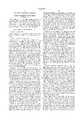
- FIG. 1is a schematic illustration, showing a top plan view of insole of a left shoe and illustrating the approximate position of the metatarsal and related bone structure of a user's left foot in relation thereto.
- FIG. 2is a bottom plan view of a pseudo-planar insole insert for a user's left foot, in accordance with the present invention.
- FIG. 3is a side elevational view taken from the lateral side of the pseudo-planar insole insert shown in FIG. 2.
- FIG. 4is a cross-sectional view of the pseudo-planar insole insert, taken along line 4--4 of FIG. 2.
- FIG. 5is a cross-sectional view of the pseudo-planar insole insert, taken along line 5--5 of FIG. 2, according to the present invention.
- the reference numeral 1generally refers to a pseudo-planar insole insert in accordance with the present invention, as shown in FIGS. 1 through 5.
- the pseudo-planar insole insert 1comprises a body member 11 having a first or upper member 13 with a planar first upper surface 15 for comfortable stable support of a wearer's foot and a planar second or second surface 17, and a second or second member 23 with a planar first or upper surface 25 and a planar second or lower surface 27 for generally bearing against the insole of a wearer's shoe.
- the first member 13 and the second member 23are molded, glued, or otherwise formed or constructed from one or more pliable materials that provides the desired cushioning, light weight, physical characteristics, wearability, breathability, rot resistance, slip resistance, durability for long use, and relative inertness that does not commonly contribute to allergic reactions when in contact with skin.
- the first member 13may be formed of any suitable material, such as DPU sometimes referred to as blown thermoplastic rubber, polyurethane, TPR, PVC, EVA or other material well known to those of ordinary skill in the art of footwear.
- the material selectedis also one that may be treated with a pair of scissors or shears for more precisely adapting, or custom fitting, the pseudo-planar insole insert 1 to the footwear for which it is intended.
- first member 13 and the second member 23may be reverse the relative spacing arrangement of the first member 13 and the second member 23.
- the second member 23may be superimposed between the wearer's foot and the first member 13, whereas the first member 13 may be spaced between the second member 23 and the insole of the user's shoe.
- the upper surface 15 of the body member 11may be overlaid with a thin fabric liner or other suitable pliable sheet-like material, to separate the sole of the wearer's foot from direct contact with the body member 11; such a liner may be constructed of an odor and/or moisture absorbing material, as known in the art, and may also be impregnated with an antibacterial and/or antimicrobial agent.
- a thin fabric liner or other suitable pliable sheet-like materialto separate the sole of the wearer's foot from direct contact with the body member 11; such a liner may be constructed of an odor and/or moisture absorbing material, as known in the art, and may also be impregnated with an antibacterial and/or antimicrobial agent.
- any particular one (or pair) of the pseudo-planar insole insert 1may vary as is customary, depending upon the size of footwear for which that pseudo-planar insole insert 1 is intended.
- Various dimensionsare quantified herein for exemplary purposes only; those quantities were observed for a pseudo-planar insole insert 1 of the present invention for a woman's size nine, oxford-type shoe, sometimes referred to herein as the " woman's size-nine exemplary specimen". It is to be understood that those dimensions may increase or decrease according to the shoe size for which a particular set of the pseudo-planar insole inserts 1 is to be utilized.
- regions of the first member 13are defined as a toe edge 31, a heel edge 33, a medial side edge 35, and a lateral side edge 37 corresponding to parts of the user's foot.
- the toe edge 31, the heel edge 33, the medial side edge 35, and the lateral side edge 37are generally profiled and dimensioned to fit just within the corresponding sides and toe of the user's footwear.
- the first member 13preferably has a uniform thickness, generally in the range of approximately two to six millimeters.
- the first member 13 of the woman's size-nine exemplary specimen of the pseudo-planar insole insert 1has a thickness of approximately 5 mm.
- the first member 13preferably has a Type C (commonly referred to as "Shore C Scale") durometer hardness measured in accordance with American Society of Testing and Material (ASTM) standard D 2440-97 of less than about 70 and more preferably a hardness in a range of about 40-65.
- ASTMAmerican Society of Testing and Material
- the hardnessmay be greater or lesser as desired. For example, if the footwear is intended for walking, the first member 13 may have a Type C durometer hardness (ASTM D 2240-97) of about 45, whereas if the footwear is intended for running, the first member 13 may have a hardness of about 60.
- the pseudo-planar insole insert 1may have a hardness of approximately 55 on the Shore C Scale.
- the first member 13should be sufficiently “soft” to provide shock attenuation, but sufficiently firm to provide stability to the user's foot.
- the second member 23is preferably constructed of the same type of material as the first member 13, with the first surface 25 thereof laminated or otherwise secured to the second surface 17 of the first member 13, such as by heat fusion, adhesive, a chemicsome curing process, or any other suitable method.
- the second member 23may have the same thickness as the first member 13 or, alternatively, the second member 23 may be thicker than the first member 13.
- the second member 23generally has a uniform thickness in the range of two to six millimeters. Preferably, however, the second member 23 has a uniform thickness that is substantially thinner than the thickness of the first member 13. For example, in the woman's size-nine exemplary specimen of the pseudo-planar insole insert 1, the second member 23 has a thickness of approximately 2 mm.
- cellular materialfor supporting purposes.
- non-cellular materialsuch as an elastomeric material
- cushioning purposesfor cushioning purposes.
- non-cellular material for the first member 13 and cellular material for the second member 23it may be desirable to use non-cellular material for the first member 13 and cellular material for the second member 23.
- first member 13 and the second member 23may be constructed of differently colored materials to enhance the aesthetic characteristics of the pseudo-planar insole insert 1 and/or to highlight the use of distinct layers for the first member 13 and the second member 23 that otherwise may appear to form a substantially planar unit when, in fact, the two-layer combination of the first member 13 and the second member 23 provides benefits not previously realized with prior art planar insole inserts.
- the second member 23has an inner edge 41, a heel edge 43, a medial side edge 45, and a lateral side edge 47.
- the heel edge 43, the medial side edge 45, and the lateral side edge 47 of the second member 23are profiled and dimensioned to fit flush with, or just within as indicated by the dashed line designated by the numeral 51 in FIG. 2, the corresponding heel edge 33, the medial side edge 35, and the lateral side edge 37 of the first member 13.
- the inner edge 41defmes the innermost extremities of an arch portion 53 and a heel portion 55 of the second member 23, wherein the heel portion 55 has a medial portion 63, a rear portion 65, and a lateral portion 67 as hereinafter described.
- the heel portion 55can be described as having a U-shaped configuration.
- the medial portion 63, the rear portion 65, and the lateral portion 67 of the heel portion 55have widths in the approximate range of 1/4 inch to 3/4 inch, depending on size of the user's foot.
- the overlaying of the first member 13 over the second member 23effectively moderates any ridging and creasing effects in the user's sole by the inner edge 41 of the second member 23 lying within the confines of the toe edge 31, the heel edge 33, the lateral side edge 37, and the medial side edge 35 of the first member 13.
- the lateral portion 67 of the heel portion 55extends forwardly along the lateral side edge 37, as shown in FIG. 2, to terminate at a foremost end 73 thereof.
- the lateral portion 67 of the heel portion 55is configured to operatively extend distally to approximately beneath a distal end of the lateral margin of the plantar calcaneal tuberosity of the user's foot.
- the medial portion 63 of the heel portion 55extends forwardly along the medial side edge 35 to join the arch portion 53, as shown in FIG. 2.
- the arch portion 53extends forwardly along the medial side edge 35 from the medial portion 63 of the heel portion 55 to terminate at a fore medial segment 75 of the inner edge 41 as shown in FIG. 2, the fore medial segment 75 having a transverse segment 77, a longitudinal segment 83, and an intermediate segment 85.
- the medial portion 63 and the arch portion 53 of the woman's size-nine exemplary specimengenerally extends forwardly to approximately seventy percent of the overall length of the pseudo-planar insole insert 1.
- the longitudinal segment 83is dimensioned and configured to be operatively spaced between the user's first and second metatarsal phalangeal joints J1, J2, and the transverse segment 77 is dimensioned and configured to be spaced just rearwardly from the first metatarsal phalangeal joint J1 such that the transverse segment 77 and the longitudinal segment 83 effectively form a metatarsal cutout 87 in the second member 23 to thereby provide operative flexibility for the first metatarsal phalangeal joint, such that the first metatarsal phalangeal joint and its associated plantar sesamoids can appropriately plantar flex between midstance and toe-off phases of a user's gait.
- the intermediate segment 85 of the inner edge 41is dimensioned and configured to terminate approximately below the second, third, and perhaps fourth metatarsal necks to provide necessary stability and support therefor.
- the fore medial segment 75passes approximately beneath the neck of the first metatarsal head, and the intermediate segment 85 passes approximately or directly beneath the second, third, and perhaps fourth metatarsals.
- the metatarsal cutout 87is configured to permit the user's first metatarsal-phalangeal joint J1 to move vertically downwardly while walking.
- the metatarsal cutout 87which is generally spaced such that the user's first metatarsal phalangeal joint J1 is spaced approximately centrally there over, is configured to have sufficient horizontal dimensions to properly accommodate the user's paired sesamoid bones located beneath his first metatarsal joint J1 to thereby allow proper, natural flexion of the user's metatarsal phalangeal joints despite the user's foot being confined to an article of footwear.
- the metatarsal cutout 87permits the first metatarsal phalangeal joint J1 to be displaced more naturally relative to the adjacent metatarsals to promote increased stability and greater balance to the extrinsic musculature of the foot and to minimize or eliminate the incidence of saddle joint deformity.
- Operatively depressing the first member 13 into the metatarsal cutout 87is also configured to basically cup the first metatarsal phalangeal joint J1 to thereby essentially fix the support provided by the pseudo-planar insole insert 1 securely in the footwear against the user's foot and, additionally, to prevent forward slippage of the user's foot in the footwear.
- the metatarsal cutout 87may have a generally trapezoidal, circular, rectangular, or triangular shape, or may have any other suitable shape so long as the metatarsal cutout 87 is properly dimensioned to, cooperatively with other components of the pseudo-planar insole insert 1, accomplish desired foot functioning and redistribution of the weight-generated forces bearing against the sole of the user's foot during the various phases of gait as described herein.
- the inner edge 41also includes an aft medial segment 93 of the pseudo-planar insole insert 1 that extends generally from the region of the third or fourth metatarsal joints J3, J4, continues rearwardly approximately beneath the lateral cuneiform bone 95, and curves gradually in a rearward and medial direction to pass approximately beneath the navicular bone 97 to then form the inner extremities of the medial portion 63, the rear portion 65, and the lateral portion 67 of the heel portion 55, as shown in FIGS. 1 and 2.
- the medial portion 63, the rear portion 65, and the lateral portion 67 of the heel portion 55extend inwardly respectively from the medial side edge 45, the heel edge 43, and the lateral side edge 47 to form a generally semi-circular profile 103 about a center of curvature 105.
- each of the medial portion 63 and the lateral portion 67 of the heel portion 55 of the woman's size-nine exemplary specimen of the pseudo-planar insole insert 1has a width transversely from the center of curvature 105 of approximately twenty percent of the overall transverse width of the pseudo-planar insole insert 1 through the center of curvature 105.
- the rear portion 65 of the heel portion of the woman's size-nine exemplary specimen of the pseudo-planar insole insert 1has a width directly rearwardly from the center of curvature 105 of approximately five percent of the overall length of the pseudo-planar insole insert 1.
- the heel portion 55 and the arch portion 53are configured and dimensioned to cooperatively redistribute the relatively large weight-generated forces normally bearing against the sesamoids and the central region of the user's heel, that are induced during various supported phases of the user's gait, to other areas of the user's sole that normally experience smaller weight-generated forces to thereby substantially reduce the range of such forces bearing against the sole of the user's foot.
- the portions 63, 65, 67in conjunction with each other and with the arch portion 53, operatively shift the weight-bearing forces normally bearing against the sole of the user's foot from the more bony structure of the user's heel outwardly toward the larger and more fleshy areas of the user's heel, arch, and forefoot.
- the heel portion 55in conjunction with the arch portion 53, is configured to redistribute the weight-generated forces from the center of the user's heel outwardly to thereby reduce or eliminate the incidence of bruising of the bottom center of the user's heel.
- the heel portion 43 and the arch portion 53are cooperatively configured such that a larger portion of the user's body weight is distributed over a larger area of the sole of the user's foot.
- the heel portion 55 and the arch portion 53are cooperatively configured such that an increased portion of the user's weight is supported by the regions of the user's foot between the user's heel and forefoot, providing a bridging effect which operatively reduces the overall weight-bearing forces applied to the user's heel and forefoot during the midstance phase of the user's gait
- the user's footis supported at an elevation, i.e., suspended, slightly above the elevation at which it would otherwise be supported were it not for the heel portion 55 and the arch portion 53.
- the heel portion 55 and the arch portion 53in conjunction with the metatarsal cutout 87, redistribute the larger weight-generated forces normally applied to the user's sesamoids away from the sesamoids toward other areas of the user's forefoot, such as the second and third metatarsals.
- the arch portion 53 and the metatarsal cutout 87are configured such that cooperative interaction therebetween reduces first ray instability by providing relatively more support to the talonavicular joint which, in turn, reduces the stress on adjacent metatarsals, thereby decreasing or eliminating the incidence of metatarsal stress fractures. Also, the arch portion 53 and the metatarsal cutout 87 are configured to promote more natural control of the talonavicular joint to thereby decrease or eliminate the incidence of shin splints and fatigue of the front and back leg muscles, and to thereby promote more efficient movement of the user's lower leg muscles.
- the heel cutout 107 of the woman's size-nine exemplary specimen of the pseudo-planar insole insert 1has a width of approximately sixty percent of the overall transverse width through the center of curvature 105 of the pseudo-planar insole insert 1.
- the operative structural and contour features of the pseudo-planar insole insert 1, namely the heel portion 55 and the arch portion 53, in conjunction with the heel cutout 107,are configured to redistribute the weight-generated forces normally applied in the central region of the user's heel outwardly therefrom to thereby reduce or eliminate the incidence of bruising in the central region of the user's heel.
- the metatarsal cutout 87, the heel portion 55, and the arch portion 53are configured to cooperatively provide the pseudo-planar insole insert 1 with the ability to permit a user's foot to be secure and stable as necessary for appropriate flexing and movement of the bone structure throughout the supported phases of gait in most existing footwear that do not otherwise provide such security and stability.
- the metatarsal cutout 87, the heel portion 55, and the arch portion 53are configured such that cooperative interaction there among largely minimizes or eliminates excessive inward rotation of the user's leg to thereby reduce knee and hip discomforts sometimes associated therewith.
- the body member 11, the metatarsal cutout 87, the heel portion 55, and the arch portion 53are configured such that cooperative interaction there among will more naturally balance the extrinsic muscles on the top and bottom of the user's foot to thereby minimize or entirely eliminate the maladies commonly referred to as bunions and hammertoes.
- a state-of-the-art systemdeveloped for measuring the distribution of weight-generated forces applied to the sole of a user's foot, sometimes referred to as "F-scan in-shoe gait analysis", was used to evaluate the inventive features of the pseudo-planar insole insert 1 of the present invention.
- the F-scan systemuses paper-thin insole devices, each approximately 0.007-inch thick and containing on the order of a thousand individual sensors.
- the F-scan insole devicesare flexible and may be trimmed to custom fit almost any shoe size or shape.
- the F-scan insolesare attached directly to the bottom of a sock or the skin of a user's sole before insertion into footwear.
- the bi-pedal plantar pressures at each of the sensorsare then detected, monitored, and recorded by the F-scan system as they sequentially occur during a normal gait cycle and/or during stance.
- the resultsmay then be compared with similar measurements taken with the same or similar footwear, one set with modifications such as the pseudo-planar insole insert 1, and one set without such modifications.
- F-scan computerized gait analysis systemwas used for diagnostic evaluations of footwear not providing the benefits of the pseudo-planar insole insert 1 and compared with corresponding diagnostic evaluations of footwear utilizing the pseudo-planar insole insert 1 of the present invention.
- a comparison of two corresponding sets of F-scan datadisclosed that the greatest weight-generated forces at the center of the user's heel were reduced from 22.2 kilograms per square centimeter (kg/cm 2 ) without the pseudo-planar insole insert 1 to 19.7 kg/cm 2 with the pseudo-planar insole insert 1, or a reduction in excess of eleven percent; at the greatest weight-generated forces applied to the sesamoids of the user's foot were reduced from 17.8 kg/cm 2 without the pseudo-planar insole insert 1 to 13.5 kg/cm 2 with the pseudo-planar insole insert 1, or a reduction in excess of twenty-four percent; and at the greatest weight-generated forces applied to the fifth metatarsal head of the user's foot were reduced from 26.0 kg/cm 2 without the pseudo-planar insole insert 1 to 13.5 kg/cm 2 with the pseudo-planar insole insert 1, or a reduction of approximately forty-eight percent.
- the pseudo-planar insole insert 1 of the present inventioncomprises a first planar material positioned for attenuating the impact forces applied to the user's foot and other skeletal structures during standing, walking and running, and a combination of the first planar material with a, generally thinner, profiled second planar material for firm supporting the user's foot.
- the material of the first member 13 and the second member 23compresses relatively easily when loaded. However, the regions of the pseudo-planar insole insert 1 wherein the first member 13 is superimposed over the second member 23 do not compress as compactly when loaded as those regions wherein the first member 13 is not superimposed over the second member 23.
- the regions of the body member 11 that include the combination of both the first member 13 and the second member 23are configured to, among other things, compress and provide firmer support for the corresponding regions of the user's foot, whereas the regions of the body member 11 that include only the first member 13, but not the second member 23, are configured to, among other things, redistribute some of the larger weight-generated forces normally bearing against the user's sole in the regions corresponding to those regions of the first member 13 not supported by the second member 23 toward those regions of the first member 13 that are supported by the second member 23.
- the region of the body member 11 corresponding to the arch portion 53finely supports the osseous alignment of the user's foot when in the neutral position thereby relieving stress in the ligaments, muscles and tendons which maintain the foot in that position.
- the arch portion 53provides necessary support for the second and third (and perhaps fourth, N4) metatarsal necks N2, N3, but the region of the first member 13 corresponding to the metatarsal cutout 87 permits the first metatarsal neck N1 and head M1 to plantarflex relative to the second and third metatarsal heads M2, M3.
- the structural and contour features of the first member 13 in combination with the second member 23are configured to cooperatively provide the pseudo-planar insole insert 1 with the ability to permit a user's foot to be secure and stable as necessary for appropriate flexing and movement of the bone structure throughout the phases of gait in most existing footwear that do not otherwise provide such security and stability.
- the resiliency of the lateral portion 67 of the heel portion 55 of the pseudo-planar insole insert 1, in addition to cooperatively redistributing weight-generated forces applied to the user's foot,also provides cushioning for those initial impacts to thereby reduce risk of injury to the user and to thereby support and promote enhanced efficiency of other associated parts of the user's foot and lower skeletal structure.
- the pseudo-planar insole insert 1is appropriately installed in existing footwear and worn on a user's foot, some of the primary benefits provided by the pseudo-planar insole insert 1 while walking and running begin at heel strike, when the heel of the user's footwear first hits the underlying supporting surface.
- the user's footpivots distally about his heel, with the lateral sides of his arch and forefoot impacting against the underlying supporting surface and his foot pronating to a neutral position with the central vertical plane of his heel generally appropriately oriented perpendicularly to the underlying supporting surface.
- resiliency of the body member 11 of the pseudo-planar insole insert 1provides cushioning for the shocks arising from such secondary impacts.
- the first metatarsal phalangeal jointstabilizes as it must before the user's foot subsequently lifts from the underlying supporting surface.
- the lesser phalangeal jointsare accordingly stabilized due to the contours of the second member 23, including the metatarsal cutout 87 for the first metatarsal phalangeal joint J1.
- the resiliency of the body member 11 beneath the user's metatarsal heads M1-M5also serves to attenuate and/or redistribute weight-generated forces applied there against during mid-stance through propulsive phases of his gait cycle.
- the described motionplaces the user's foot in an appropriate biomechanical position for the propulsive phase of his gait cycle, including proper displacing of his sesamoid apparatus during mid-stance and toe-off phases.
- the cooperative interaction by the heel portion 55, the arch portion 53, and the body member 11allows the sesamoids and certain muscles of the user's foot to momentarily rest to thereby create a desirable timing sequence thereof and, particularly in conjunction with the metatarsal cutout 87, to create a more effective lever system just prior to the foot progressing into the toe-off phase of his gait.
- the first metatarsal M1is permitted by the interaction between the first member 13 and the second member 23 to be appropriately pushed downwardly, remaining stable, particularly due to the support provided to the second and third metatarsals by the second member 23 as the user's heel lifts from the underlying supporting surface, and continuing to remain stable and appropriately flex without movement upward or forward up to the position in the user's gait whereat the first metatarsal phalangeal joint J1 lifts from the underlying supporting surface.
- the pseudo-planar insole insert 1allows the user's first metatarsal phalangeal joint J1 to actually displace downwardly to continue to be stabilized, thereby progressively providing appropriate functioning of the user's foot throughout the entire supported phases of his gait.
- the structure of the pseudo-planar insole insert 1provides support and stability for each of the user's heel, arch, and first metatarsal from before the user's foot rotates forwardly, whereat his heel lifts from the underlying supporting surface, to the point in the user's gait whereat the user's first metatarsal actually lifts from the underlying supporting surface.
- the pseudo-planar insole insert 1appropriately provides all of the necessary supporting and stabilizing factors while allowing the user's foot to function appropriately within the confines of his shoe.
- the material properties of the various regions of the pseudo-planar insole insert 1appropriately cushion, support and stabilize various parts of the user's foot as herein described. It should also now be obvious that the resiliencies hereinbefore described may be altered, depending upon the intended use of the footwear for which the pseudo-planar insole insert 1 is intended. For example, adult footwear designed for use in situations where the wearer will frequently be carrying a heavy load (e.g., work boots) may require more support than a child's dress shoe. Likewise, footwear made for running may require firmer support in the heel section to thereby absorb the greater initial shock of each running step than would a hiking boot in which more cushioning may be desired for each walking step. Further, it will be appreciated that the present invention is not limited necessarily to any particular type of footwear and may be equally desirable for use in shoes and boots.
- Use of the pseudo-planar insole insert 1 of the present invention in a child's shoeshould preferably be initiated as soon as the infant's feet become weight-bearing to thereby aid the child in standing and walking, to mold the child's foot into an appropriate position that does not interfere with the foot's normal ontogenetic development, and to provide substantially full and complete support between the child's foot and the underlying supporting surface.
Landscapes
- Health & Medical Sciences (AREA)
- Epidemiology (AREA)
- General Health & Medical Sciences (AREA)
- Public Health (AREA)
- Chemical & Material Sciences (AREA)
- Engineering & Computer Science (AREA)
- Materials Engineering (AREA)
- Footwear And Its Accessory, Manufacturing Method And Apparatuses (AREA)
Abstract
Description
Claims (36)
Priority Applications (3)
| Application Number | Priority Date | Filing Date | Title |
|---|---|---|---|
| US09/024,489US6026599A (en) | 1996-05-29 | 1998-02-17 | Pseudo-planar insole insert |
| AU26815/99AAU2681599A (en) | 1998-02-17 | 1999-02-16 | Pseudo-planar insole insert |
| PCT/US1999/003258WO1999040811A1 (en) | 1998-02-17 | 1999-02-16 | Pseudo-planar insole insert |
Applications Claiming Priority (3)
| Application Number | Priority Date | Filing Date | Title |
|---|---|---|---|
| US65472696A | 1996-05-29 | 1996-05-29 | |
| US08/861,579US5787610A (en) | 1996-05-29 | 1997-05-22 | Footwear |
| US09/024,489US6026599A (en) | 1996-05-29 | 1998-02-17 | Pseudo-planar insole insert |
Related Parent Applications (1)
| Application Number | Title | Priority Date | Filing Date |
|---|---|---|---|
| US08/861,579Continuation-In-PartUS5787610A (en) | 1996-05-29 | 1997-05-22 | Footwear |
Publications (1)
| Publication Number | Publication Date |
|---|---|
| US6026599Atrue US6026599A (en) | 2000-02-22 |
Family
ID=21820850
Family Applications (1)
| Application Number | Title | Priority Date | Filing Date |
|---|---|---|---|
| US09/024,489Expired - LifetimeUS6026599A (en) | 1996-05-29 | 1998-02-17 | Pseudo-planar insole insert |
Country Status (3)
| Country | Link |
|---|---|
| US (1) | US6026599A (en) |
| AU (1) | AU2681599A (en) |
| WO (1) | WO1999040811A1 (en) |
Cited By (22)
| Publication number | Priority date | Publication date | Assignee | Title |
|---|---|---|---|---|
| US6282816B1 (en) | 2000-05-26 | 2001-09-04 | Jay W. Rosendahl | Insole for footwear |
| EP1238790A1 (en)* | 2001-03-08 | 2002-09-11 | adidas International B.V. | Midsole with support element |
| US6558339B1 (en)* | 1999-11-19 | 2003-05-06 | Michael E. Graham | Foot alleviator |
| US20030192202A1 (en)* | 2002-04-10 | 2003-10-16 | Schoenborn Mary L. | Footwear sole |
| US20040102726A1 (en)* | 2002-11-27 | 2004-05-27 | James Sullivan | Orthotic foot devices for bare feet and methods for stabilizing feet |
| US20040134098A1 (en)* | 2000-08-04 | 2004-07-15 | Hermann Beck | Shoe inner sole |
| US6889452B2 (en) | 2001-11-14 | 2005-05-10 | Boot Royalty Company, L.P. | Insole for footwear |
| US20050108899A1 (en)* | 2002-01-16 | 2005-05-26 | Rodney Kielt | Orthotic insert and method of manufacture thereof |
| US20070193071A1 (en)* | 2006-02-17 | 2007-08-23 | Andre Gilmore | First metatarsal head lift orthotic |
| US20070234593A1 (en)* | 2000-08-04 | 2007-10-11 | Caprice Schuhproduktion Gmbh & Co. Kg | Shoe inner sole |
| CH696696A5 (en)* | 2003-08-19 | 2007-10-15 | Pama Reiter Stefan | Insole. |
| US20080167580A1 (en)* | 2005-04-05 | 2008-07-10 | Andante Medical Devices Ltd. | Rehabilitation System |
| US20090031583A1 (en)* | 2007-08-03 | 2009-02-05 | Schering-Plough Healthcare Products, Inc. | Foot Support For Alleviating Knee Pain |
| CN100462021C (en)* | 2005-12-14 | 2009-02-18 | 株式会社全健康护理 | Shoe insole |
| US20090119947A1 (en)* | 2005-02-28 | 2009-05-14 | Kevan Orvitz | Orthopedic Foot Appliance |
| US7549232B2 (en) | 2003-10-14 | 2009-06-23 | Amfit, Inc. | Method to capture and support a 3-D contour |
| US20130133223A1 (en)* | 2011-11-30 | 2013-05-30 | YZ Studio, Inc. | Foot Trainer |
| EP2040576B1 (en) | 2006-07-14 | 2016-08-31 | Footbalance System Oy | Individually formed footwear |
| US20190133203A1 (en)* | 2017-11-09 | 2019-05-09 | Kwan Ho Shin | Socks with lateral plantar arches |
| US10327700B2 (en)* | 2016-02-24 | 2019-06-25 | National Tsing Hua University | Intelligent insole |
| US20220000215A1 (en)* | 2013-03-15 | 2022-01-06 | Rikco International Llc | Pressure relief system for footwear |
| US12408725B1 (en)* | 2022-04-18 | 2025-09-09 | Bernardo Birnbaum | Insole |
Citations (13)
| Publication number | Priority date | Publication date | Assignee | Title |
|---|---|---|---|---|
| US1728243A (en)* | 1927-05-04 | 1929-09-17 | Marshalek Alois | Arch support |
| US1957695A (en)* | 1933-04-11 | 1934-05-08 | Baptist A Chiappetta | Arch support |
| US1992081A (en)* | 1934-05-01 | 1935-02-19 | Gottlieb F Madinger | Arch supporter |
| US2161565A (en)* | 1938-06-10 | 1939-06-06 | Severino A Freda | Arch supporter |
| US2252936A (en)* | 1938-03-05 | 1941-08-19 | Charles P Leydecker | Method of balancing a foot within a shoe |
| US2628440A (en)* | 1951-02-12 | 1953-02-17 | Charles P Leydecker | Foot balancing means |
| US3591882A (en)* | 1969-08-21 | 1971-07-13 | Usm Corp | Chemical manufacture |
| US4266350A (en)* | 1979-08-20 | 1981-05-12 | Ormid Company | Footwear insole |
| US4360027A (en)* | 1981-06-29 | 1982-11-23 | Bruce Friedlander | Thin, light-weight flexible orthopedic device |
| US4813157A (en)* | 1986-07-21 | 1989-03-21 | Michelle Boisvert | Adjustable shoe insole |
| US4841648A (en)* | 1988-02-29 | 1989-06-27 | Shaffer David E | Personalized insole kit |
| US5058585A (en)* | 1990-01-29 | 1991-10-22 | Michael Kendall | Orthotic shoe insert |
| US5787610A (en)* | 1996-05-29 | 1998-08-04 | Jeffrey S. Brooks, Inc. | Footwear |
Family Cites Families (4)
| Publication number | Priority date | Publication date | Assignee | Title |
|---|---|---|---|---|
| US4137654A (en)* | 1977-02-07 | 1979-02-06 | Sports Safety, Inc. | Footwear device |
| AT397602B (en)* | 1991-03-27 | 1994-05-25 | Leder & Schuh Aktiengesellscha | INSOLE, IN PARTICULAR INSOLE, FOR SHOES |
| US5669162A (en)* | 1996-03-07 | 1997-09-23 | Brown Group, Inc. | Cushion insert |
| DE19609177B4 (en)* | 1996-03-11 | 2005-03-03 | Stumpf, Jürgen | Footbed sole or shoe insert |
- 1998
- 1998-02-17USUS09/024,489patent/US6026599A/ennot_activeExpired - Lifetime
- 1999
- 1999-02-16AUAU26815/99Apatent/AU2681599A/ennot_activeAbandoned
- 1999-02-16WOPCT/US1999/003258patent/WO1999040811A1/enactiveApplication Filing
Patent Citations (13)
| Publication number | Priority date | Publication date | Assignee | Title |
|---|---|---|---|---|
| US1728243A (en)* | 1927-05-04 | 1929-09-17 | Marshalek Alois | Arch support |
| US1957695A (en)* | 1933-04-11 | 1934-05-08 | Baptist A Chiappetta | Arch support |
| US1992081A (en)* | 1934-05-01 | 1935-02-19 | Gottlieb F Madinger | Arch supporter |
| US2252936A (en)* | 1938-03-05 | 1941-08-19 | Charles P Leydecker | Method of balancing a foot within a shoe |
| US2161565A (en)* | 1938-06-10 | 1939-06-06 | Severino A Freda | Arch supporter |
| US2628440A (en)* | 1951-02-12 | 1953-02-17 | Charles P Leydecker | Foot balancing means |
| US3591882A (en)* | 1969-08-21 | 1971-07-13 | Usm Corp | Chemical manufacture |
| US4266350A (en)* | 1979-08-20 | 1981-05-12 | Ormid Company | Footwear insole |
| US4360027A (en)* | 1981-06-29 | 1982-11-23 | Bruce Friedlander | Thin, light-weight flexible orthopedic device |
| US4813157A (en)* | 1986-07-21 | 1989-03-21 | Michelle Boisvert | Adjustable shoe insole |
| US4841648A (en)* | 1988-02-29 | 1989-06-27 | Shaffer David E | Personalized insole kit |
| US5058585A (en)* | 1990-01-29 | 1991-10-22 | Michael Kendall | Orthotic shoe insert |
| US5787610A (en)* | 1996-05-29 | 1998-08-04 | Jeffrey S. Brooks, Inc. | Footwear |
Cited By (36)
| Publication number | Priority date | Publication date | Assignee | Title |
|---|---|---|---|---|
| US6558339B1 (en)* | 1999-11-19 | 2003-05-06 | Michael E. Graham | Foot alleviator |
| US6282816B1 (en) | 2000-05-26 | 2001-09-04 | Jay W. Rosendahl | Insole for footwear |
| US7703219B2 (en) | 2000-08-04 | 2010-04-27 | Caprice Schuhproduktion Gmbh & Co. Kg | Shoe inner sole |
| US20040134098A1 (en)* | 2000-08-04 | 2004-07-15 | Hermann Beck | Shoe inner sole |
| US20070234593A1 (en)* | 2000-08-04 | 2007-10-11 | Caprice Schuhproduktion Gmbh & Co. Kg | Shoe inner sole |
| US20070158873A1 (en)* | 2000-08-04 | 2007-07-12 | Caprice Schuhproduktion Gmbh & Co. Kg | Process for making a shoe inner sole |
| EP1238790A1 (en)* | 2001-03-08 | 2002-09-11 | adidas International B.V. | Midsole with support element |
| DE10111229C5 (en)* | 2001-03-08 | 2009-01-29 | Adidas International Marketing B.V. | Sole element with support element, method for its production and shoe with sole element |
| US20060053657A1 (en)* | 2001-11-14 | 2006-03-16 | Ailey James H | Insole for footwear |
| US20070144038A1 (en)* | 2001-11-14 | 2007-06-28 | Ailey James H | Insole for footwear |
| US6889452B2 (en) | 2001-11-14 | 2005-05-10 | Boot Royalty Company, L.P. | Insole for footwear |
| US7637034B2 (en) | 2001-11-14 | 2009-12-29 | Boot Royalty Company, L.P. | Insole for footwear |
| US20050108899A1 (en)* | 2002-01-16 | 2005-05-26 | Rodney Kielt | Orthotic insert and method of manufacture thereof |
| US7458173B2 (en)* | 2002-01-16 | 2008-12-02 | Foot Steps Orthotics Pty Limited | Orthotic insert and method of manufacture thereof |
| US6880266B2 (en)* | 2002-04-10 | 2005-04-19 | Wolverine World Wide, Inc. | Footwear sole |
| US20030192202A1 (en)* | 2002-04-10 | 2003-10-16 | Schoenborn Mary L. | Footwear sole |
| US7041075B2 (en)* | 2002-11-27 | 2006-05-09 | James Sullivan | Orthotic foot devices for bare feet and methods for stabilizing feet |
| US20040102726A1 (en)* | 2002-11-27 | 2004-05-27 | James Sullivan | Orthotic foot devices for bare feet and methods for stabilizing feet |
| CH696696A5 (en)* | 2003-08-19 | 2007-10-15 | Pama Reiter Stefan | Insole. |
| US7549232B2 (en) | 2003-10-14 | 2009-06-23 | Amfit, Inc. | Method to capture and support a 3-D contour |
| US8069586B2 (en)* | 2005-02-28 | 2011-12-06 | Kevan Orvitz | Orthopedic foot appliance |
| US20090119947A1 (en)* | 2005-02-28 | 2009-05-14 | Kevan Orvitz | Orthopedic Foot Appliance |
| WO2006106516A3 (en)* | 2005-04-05 | 2009-05-07 | Andante Medical Devices Ltd | Rehabilitation system |
| US20080167580A1 (en)* | 2005-04-05 | 2008-07-10 | Andante Medical Devices Ltd. | Rehabilitation System |
| CN100462021C (en)* | 2005-12-14 | 2009-02-18 | 株式会社全健康护理 | Shoe insole |
| US20070193071A1 (en)* | 2006-02-17 | 2007-08-23 | Andre Gilmore | First metatarsal head lift orthotic |
| US7832119B2 (en) | 2006-02-17 | 2010-11-16 | Solution Source | First metatarsal head lift orthotic |
| EP2040576B1 (en) | 2006-07-14 | 2016-08-31 | Footbalance System Oy | Individually formed footwear |
| US20090031583A1 (en)* | 2007-08-03 | 2009-02-05 | Schering-Plough Healthcare Products, Inc. | Foot Support For Alleviating Knee Pain |
| US20130133223A1 (en)* | 2011-11-30 | 2013-05-30 | YZ Studio, Inc. | Foot Trainer |
| US9345284B2 (en)* | 2011-11-30 | 2016-05-24 | YZ Studio, Inc. | Foot trainer |
| US20220000215A1 (en)* | 2013-03-15 | 2022-01-06 | Rikco International Llc | Pressure relief system for footwear |
| US11737508B2 (en)* | 2013-03-15 | 2023-08-29 | Rikco International Llc | Pressure relief system for footwear |
| US10327700B2 (en)* | 2016-02-24 | 2019-06-25 | National Tsing Hua University | Intelligent insole |
| US20190133203A1 (en)* | 2017-11-09 | 2019-05-09 | Kwan Ho Shin | Socks with lateral plantar arches |
| US12408725B1 (en)* | 2022-04-18 | 2025-09-09 | Bernardo Birnbaum | Insole |
Also Published As
| Publication number | Publication date |
|---|---|
| AU2681599A (en) | 1999-08-30 |
| WO1999040811A1 (en) | 1999-08-19 |
Similar Documents
| Publication | Publication Date | Title |
|---|---|---|
| US6131311A (en) | Insole insert for footwear | |
| US6026599A (en) | Pseudo-planar insole insert | |
| US5964046A (en) | Footwear | |
| CA2643673C (en) | An orthopedic foot appliance | |
| US6880266B2 (en) | Footwear sole | |
| US20040103561A1 (en) | Footwear with orthopedic component system | |
| US6854198B2 (en) | Footwear | |
| US20010032400A1 (en) | Footwear outsole having arcuate inner-structure | |
| US4979318A (en) | Pronatary insert for high-heeled shoes | |
| EP3331392B1 (en) | Orthotic device for shoes | |
| US20020162250A1 (en) | Unitary orthotic insert and orthopedic insole | |
| WO1992021258A1 (en) | Tripod support for the human foot | |
| WO2021173898A1 (en) | An in-shoe insole to provide comfort and reduce pain in high heeled shoes and boots, constructed from an anatomically shaped last | |
| US6321468B1 (en) | Footwear outsole having arcuate inner-structure | |
| WO1999053785A1 (en) | Insole insert having perforation-modified resiliency | |
| WO1999053786A1 (en) | Laminated insole insert for footwear | |
| CA3210210C (en) | Auxiliary or integrated inner sole structure for footwear | |
| CN118695793A (en) | Auxiliary or integrated internal sole structures for footwear | |
| Helfand | Basic considerations for shoes, shoe modifications, and orthoses in foot care | |
| Johnson | Running shoes and orthoses: a practical approach | |
| AU3732989A (en) | Pronatary insert for high-heeled shoes | |
| NZ535902A (en) | Orthotic with deep heeled cup, medial heel wedge and arch support, and lower profiled lateral mid-foot and flat forefoot regions | |
| HK1099493B (en) | Footwear sole |
Legal Events
| Date | Code | Title | Description |
|---|---|---|---|
| AS | Assignment | Owner name:PAYLESS SHOESOURCE, INC., KANSAS Free format text:ASSIGNMENT OF ASSIGNORS INTEREST;ASSIGNORS:BLACKWELL, TERRY DEAN;BROOKS, JEFFREY S.;REEL/FRAME:009180/0880;SIGNING DATES FROM 19980216 TO 19980217 | |
| STCF | Information on status: patent grant | Free format text:PATENTED CASE | |
| FPAY | Fee payment | Year of fee payment:4 | |
| FPAY | Fee payment | Year of fee payment:8 | |
| FPAY | Fee payment | Year of fee payment:12 | |
| AS | Assignment | Owner name:WELLS FARGO BANK, NATIONAL ASSOCIATION, MASSACHUSE Free format text:SECURITY AGREEMENT;ASSIGNORS:CLINCH, LLC;COLLECTIVE BRANDS FINANCE, INC.;COLLECTIVE BRANDS FRANCHISING SERVICES, LLC;AND OTHERS;REEL/FRAME:029108/0001 Effective date:20121009 | |
| AS | Assignment | Owner name:MORGAN STANLEY SENIOR FUNDING, INC. A NATIONAL BAN Free format text:SECURITY AGREEMENT;ASSIGNORS:PAYLESS CUSTOMER SERVICE SOLUTION, LLC;COLLECTIVE LICENSING, LP;PAYLESS COLLECTIVE GP, LLC;AND OTHERS;REEL/FRAME:029138/0112 Effective date:20121009 | |
| AS | Assignment | Owner name:EASTBOROUGH, INC., KANSAS Free format text:RELEASE BY SECURED PARTY;ASSIGNOR:MORGAN STANLEY SENIOR FUNDING, INC.,;REEL/FRAME:032438/0045 Effective date:20140311 Owner name:PAYLESS SHOESOURCE WORLDWIDE, INC., KANSAS Free format text:RELEASE BY SECURED PARTY;ASSIGNOR:MORGAN STANLEY SENIOR FUNDING, INC.,;REEL/FRAME:032438/0045 Effective date:20140311 Owner name:COLLECTIVE BRANDS SERVICES, INC., KANSAS Free format text:RELEASE BY SECURED PARTY;ASSIGNOR:MORGAN STANLEY SENIOR FUNDING, INC.,;REEL/FRAME:032438/0045 Effective date:20140311 Owner name:COLLECTIVE BRANDS FRANCHISING SERVICES, LLC, KANSA Free format text:RELEASE BY SECURED PARTY;ASSIGNOR:MORGAN STANLEY SENIOR FUNDING, INC.,;REEL/FRAME:032438/0045 Effective date:20140311 Owner name:PAYLESS PURCHASING SERVICES, INC., KANSAS Free format text:RELEASE BY SECURED PARTY;ASSIGNOR:MORGAN STANLEY SENIOR FUNDING, INC.,;REEL/FRAME:032438/0045 Effective date:20140311 Owner name:COLLECTIVE BRANDS, LLC, KANSAS Free format text:RELEASE BY SECURED PARTY;ASSIGNOR:MORGAN STANLEY SENIOR FUNDING, INC.,;REEL/FRAME:032438/0045 Effective date:20140311 Owner name:COLLECTIVE BRANDS FINANCE, INC., KANSAS Free format text:RELEASE BY SECURED PARTY;ASSIGNOR:MORGAN STANLEY SENIOR FUNDING, INC.,;REEL/FRAME:032438/0045 Effective date:20140311 Owner name:COLLECTIVE BRANDS, INC., KANSAS Free format text:RELEASE BY SECURED PARTY;ASSIGNOR:MORGAN STANLEY SENIOR FUNDING, INC.,;REEL/FRAME:032438/0045 Effective date:20140311 Owner name:PAYLESS GOLD VALUE WY, INC., KANSAS Free format text:RELEASE BY SECURED PARTY;ASSIGNOR:MORGAN STANLEY SENIOR FUNDING, INC.,;REEL/FRAME:032438/0045 Effective date:20140311 Owner name:PAYLESS COLLECTIVE GP, LLC, KANSAS Free format text:RELEASE BY SECURED PARTY;ASSIGNOR:MORGAN STANLEY SENIOR FUNDING, INC.,;REEL/FRAME:032438/0045 Effective date:20140311 Owner name:PAYLESS INTERNATIONAL FRANCHISING, LLC, KANSAS Free format text:RELEASE BY SECURED PARTY;ASSIGNOR:MORGAN STANLEY SENIOR FUNDING, INC.,;REEL/FRAME:032438/0045 Effective date:20140311 Owner name:DYELIGHTS, INC., KANSAS Free format text:RELEASE BY SECURED PARTY;ASSIGNOR:MORGAN STANLEY SENIOR FUNDING, INC.,;REEL/FRAME:032438/0045 Effective date:20140311 Owner name:PSS DELAWARE COMPANY 2, INC., KANSAS Free format text:RELEASE BY SECURED PARTY;ASSIGNOR:MORGAN STANLEY SENIOR FUNDING, INC.,;REEL/FRAME:032438/0045 Effective date:20140311 Owner name:PAYLESS SHOESOURCE DISTRIBUTION, INC., KANSAS Free format text:RELEASE BY SECURED PARTY;ASSIGNOR:MORGAN STANLEY SENIOR FUNDING, INC.,;REEL/FRAME:032438/0045 Effective date:20140311 Owner name:PAYLESS SHOESOURCE MERCHANDISING, INC., KANSAS Free format text:RELEASE BY SECURED PARTY;ASSIGNOR:MORGAN STANLEY SENIOR FUNDING, INC.,;REEL/FRAME:032438/0045 Effective date:20140311 Owner name:CLINCH, LLC, COLORADO Free format text:RELEASE BY SECURED PARTY;ASSIGNOR:MORGAN STANLEY SENIOR FUNDING, INC.,;REEL/FRAME:032438/0045 Effective date:20140311 Owner name:PAYLESS GOLD VALUE, LLC, KANSAS Free format text:RELEASE BY SECURED PARTY;ASSIGNOR:MORGAN STANLEY SENIOR FUNDING, INC.,;REEL/FRAME:032438/0045 Effective date:20140311 Owner name:PSS DELAWARE COMPANY 4, INC., KANSAS Free format text:RELEASE BY SECURED PARTY;ASSIGNOR:MORGAN STANLEY SENIOR FUNDING, INC.,;REEL/FRAME:032438/0045 Effective date:20140311 Owner name:PAYLESS SHOESOURCE LEASING, LLC, KANSAS Free format text:RELEASE BY SECURED PARTY;ASSIGNOR:MORGAN STANLEY SENIOR FUNDING, INC.,;REEL/FRAME:032438/0045 Effective date:20140311 Owner name:PAYLESS NYC, INC., KANSAS Free format text:RELEASE BY SECURED PARTY;ASSIGNOR:MORGAN STANLEY SENIOR FUNDING, INC.,;REEL/FRAME:032438/0045 Effective date:20140311 Owner name:WBG - PSS HOLDINGS LLC, CALIFORNIA Free format text:RELEASE BY SECURED PARTY;ASSIGNOR:MORGAN STANLEY SENIOR FUNDING, INC.,;REEL/FRAME:032438/0045 Effective date:20140311 Owner name:COLLECTIVE LICENSING INTERNATIONAL, LLC, COLORADO Free format text:RELEASE BY SECURED PARTY;ASSIGNOR:MORGAN STANLEY SENIOR FUNDING, INC.,;REEL/FRAME:032438/0045 Effective date:20140311 Owner name:COLLECTIVE LICENSING, LP, COLORADO Free format text:RELEASE BY SECURED PARTY;ASSIGNOR:MORGAN STANLEY SENIOR FUNDING, INC.,;REEL/FRAME:032438/0045 Effective date:20140311 Owner name:PAYLESS SHOESOURCE, INC., KANSAS Free format text:RELEASE BY SECURED PARTY;ASSIGNOR:MORGAN STANLEY SENIOR FUNDING, INC.,;REEL/FRAME:032438/0045 Effective date:20140311 Owner name:PAYLESS CUSTOMER SERVICE SOLUTION, LLC, KANSAS Free format text:RELEASE BY SECURED PARTY;ASSIGNOR:MORGAN STANLEY SENIOR FUNDING, INC.,;REEL/FRAME:032438/0045 Effective date:20140311 Owner name:SHOE SOURCING, INC., KANSAS Free format text:RELEASE BY SECURED PARTY;ASSIGNOR:MORGAN STANLEY SENIOR FUNDING, INC.,;REEL/FRAME:032438/0045 Effective date:20140311 | |
| AS | Assignment | Owner name:MORGAN STANLEY SENIOR FUNDING, INC., NEW YORK Free format text:GRANT OF FIRST LIEN SECURITY INTEREST IN UNITED STATES PATENTS;ASSIGNORS:CLINCH, LLC;PAYLESS FINANCE, INC.;COLLECTIVE BRANDS FRANCHISING SERVICES, LLC;AND OTHERS;REEL/FRAME:032447/0656 Effective date:20140311 | |
| AS | Assignment | Owner name:MORGAN STANLEY SENIOR FUNDING, INC., NEW YORK Free format text:SECURITY INTEREST;ASSIGNORS:CLINCH, LLC;PAYLESS FINANCE, INC.;COLLECTIVE BRANDS FRANCHISING SERVICES, LLC;AND OTHERS;REEL/FRAME:032449/0064 Effective date:20140311 | |
| AS | Assignment | Owner name:COLLECTIVE BRANDS, LLC, KANSAS Free format text:RELEASE BY SECURED PARTY;ASSIGNOR:MORGAN STANLEY SENIOR FUNDING, INC.;REEL/FRAME:043325/0308 Effective date:20170817 Owner name:PAYLESS COLLECTIVE GP, LLC, KANSAS Free format text:RELEASE BY SECURED PARTY;ASSIGNOR:MORGAN STANLEY SENIOR FUNDING, INC.;REEL/FRAME:043325/0308 Effective date:20170817 Owner name:PAYLESS SHOESOURCE DISTRIBUTION, INC., KANSAS Free format text:RELEASE BY SECURED PARTY;ASSIGNOR:MORGAN STANLEY SENIOR FUNDING, INC.;REEL/FRAME:043325/0308 Effective date:20170817 Owner name:WBG-PSS HOLDINGS LLC, KANSAS Free format text:RELEASE BY SECURED PARTY;ASSIGNOR:MORGAN STANLEY SENIOR FUNDING, INC.;REEL/FRAME:043325/0308 Effective date:20170817 Owner name:COLLECTIVE LICENSING INTERNATIONAL, LLC, KANSAS Free format text:RELEASE BY SECURED PARTY;ASSIGNOR:MORGAN STANLEY SENIOR FUNDING, INC.;REEL/FRAME:043325/0308 Effective date:20170817 Owner name:PAYLESS SHOESOURCE, INC., KANSAS Free format text:RELEASE BY SECURED PARTY;ASSIGNOR:MORGAN STANLEY SENIOR FUNDING, INC.;REEL/FRAME:043325/0308 Effective date:20170817 Owner name:PAYLESS GOLD VALUE WY, INC., KANSAS Free format text:RELEASE BY SECURED PARTY;ASSIGNOR:MORGAN STANLEY SENIOR FUNDING, INC.;REEL/FRAME:043325/0308 Effective date:20170817 Owner name:PSS DELAWARE COMPANY 2, INC., KANSAS Free format text:RELEASE BY SECURED PARTY;ASSIGNOR:MORGAN STANLEY SENIOR FUNDING, INC.;REEL/FRAME:043325/0308 Effective date:20170817 Owner name:PAYLESS SHOESOURCE MERCHANDISING, INC., KANSAS Free format text:RELEASE BY SECURED PARTY;ASSIGNOR:MORGAN STANLEY SENIOR FUNDING, INC.;REEL/FRAME:043325/0308 Effective date:20170817 Owner name:COLLECTIVE BRANDS, INC., KANSAS Free format text:RELEASE BY SECURED PARTY;ASSIGNOR:MORGAN STANLEY SENIOR FUNDING, INC.;REEL/FRAME:043325/0308 Effective date:20170817 Owner name:PSS DELAWARE COMPANY 4, INC., KANSAS Free format text:RELEASE BY SECURED PARTY;ASSIGNOR:MORGAN STANLEY SENIOR FUNDING, INC.;REEL/FRAME:043325/0308 Effective date:20170817 Owner name:PAYLESS SHOESOURCE WORLDWIDE, INC., KANSAS Free format text:RELEASE BY SECURED PARTY;ASSIGNOR:MORGAN STANLEY SENIOR FUNDING, INC.;REEL/FRAME:043325/0308 Effective date:20170817 Owner name:COLLECTIVE LICENSING, LP, KANSAS Free format text:RELEASE BY SECURED PARTY;ASSIGNOR:MORGAN STANLEY SENIOR FUNDING, INC.;REEL/FRAME:043325/0308 Effective date:20170817 Owner name:COLLECTIVE BRANDS FRANCHISING SERVICES, LLC, KANSA Free format text:RELEASE BY SECURED PARTY;ASSIGNOR:MORGAN STANLEY SENIOR FUNDING, INC.;REEL/FRAME:043325/0308 Effective date:20170817 Owner name:COLLECTIVE BRANDS SERVICES, INC., KANSAS Free format text:RELEASE BY SECURED PARTY;ASSIGNOR:MORGAN STANLEY SENIOR FUNDING, INC.;REEL/FRAME:043325/0308 Effective date:20170817 Owner name:CLINCH, LLC, KANSAS Free format text:RELEASE BY SECURED PARTY;ASSIGNOR:MORGAN STANLEY SENIOR FUNDING, INC.;REEL/FRAME:043325/0308 Effective date:20170817 Owner name:PAYLESS PURCHASING SERVICES, INC., KANSAS Free format text:RELEASE BY SECURED PARTY;ASSIGNOR:MORGAN STANLEY SENIOR FUNDING, INC.;REEL/FRAME:043325/0308 Effective date:20170817 Owner name:PAYLESS NYC, INC., KANSAS Free format text:RELEASE BY SECURED PARTY;ASSIGNOR:MORGAN STANLEY SENIOR FUNDING, INC.;REEL/FRAME:043325/0308 Effective date:20170817 Owner name:SHOE SOURCING, INC., KANSAS Free format text:RELEASE BY SECURED PARTY;ASSIGNOR:MORGAN STANLEY SENIOR FUNDING, INC.;REEL/FRAME:043325/0308 Effective date:20170817 Owner name:PAYLESS INTERNATIONAL FRANCHISING, LLC, KANSAS Free format text:RELEASE BY SECURED PARTY;ASSIGNOR:MORGAN STANLEY SENIOR FUNDING, INC.;REEL/FRAME:043325/0308 Effective date:20170817 Owner name:COLLECTIVE BRANDS FINANCE, INC., KANSAS Free format text:RELEASE BY SECURED PARTY;ASSIGNOR:MORGAN STANLEY SENIOR FUNDING, INC.;REEL/FRAME:043325/0308 Effective date:20170817 Owner name:PAYLESS SHOESOURCE LEASING, LLC, KANSAS Free format text:RELEASE BY SECURED PARTY;ASSIGNOR:MORGAN STANLEY SENIOR FUNDING, INC.;REEL/FRAME:043325/0308 Effective date:20170817 Owner name:EASTBOROUGH, INC., KANSAS Free format text:RELEASE BY SECURED PARTY;ASSIGNOR:MORGAN STANLEY SENIOR FUNDING, INC.;REEL/FRAME:043325/0308 Effective date:20170817 Owner name:COLLECTIVE BRANDS FRANCHISING SERVICES, LLC, KANSA Free format text:RELEASE BY SECURED PARTY;ASSIGNOR:WELLS FARGO BANK, NATIONAL ASSOCIATION;REEL/FRAME:043592/0044 Effective date:20170817 Owner name:PAYLESS SHOESOURCE WORLDWIDE, INC., KANSAS Free format text:RELEASE BY SECURED PARTY;ASSIGNOR:WELLS FARGO BANK, NATIONAL ASSOCIATION;REEL/FRAME:043592/0044 Effective date:20170817 Owner name:COLLECTIVE LICENSING, LP, KANSAS Free format text:RELEASE BY SECURED PARTY;ASSIGNOR:WELLS FARGO BANK, NATIONAL ASSOCIATION;REEL/FRAME:043592/0044 Effective date:20170817 Owner name:COLLECTIVE LICENSING INTERNATIONAL, LLC, KANSAS Free format text:RELEASE BY SECURED PARTY;ASSIGNOR:WELLS FARGO BANK, NATIONAL ASSOCIATION;REEL/FRAME:043592/0044 Effective date:20170817 Owner name:PAYLESS NYC, INC., KANSAS Free format text:RELEASE BY SECURED PARTY;ASSIGNOR:WELLS FARGO BANK, NATIONAL ASSOCIATION;REEL/FRAME:043592/0044 Effective date:20170817 Owner name:PAYLESS GOLD VALUE, LLC, KANSAS Free format text:RELEASE BY SECURED PARTY;ASSIGNOR:WELLS FARGO BANK, NATIONAL ASSOCIATION;REEL/FRAME:043592/0044 Effective date:20170817 Owner name:EASTBOROUGH, INC., KANSAS Free format text:RELEASE BY SECURED PARTY;ASSIGNOR:WELLS FARGO BANK, NATIONAL ASSOCIATION;REEL/FRAME:043592/0044 Effective date:20170817 Owner name:COLLECTIVE BRANDS SERVICES, INC., KANSAS Free format text:RELEASE BY SECURED PARTY;ASSIGNOR:WELLS FARGO BANK, NATIONAL ASSOCIATION;REEL/FRAME:043592/0044 Effective date:20170817 Owner name:PAYLESS SHOESOURCE MERCHANDISING, INC., KANSAS Free format text:RELEASE BY SECURED PARTY;ASSIGNOR:WELLS FARGO BANK, NATIONAL ASSOCIATION;REEL/FRAME:043592/0044 Effective date:20170817 Owner name:PAYLESS CUSTOMER SERVICE SOLUTION, LLC, KANSAS Free format text:RELEASE BY SECURED PARTY;ASSIGNOR:WELLS FARGO BANK, NATIONAL ASSOCIATION;REEL/FRAME:043592/0044 Effective date:20170817 Owner name:PAYLESS PURCHASING SERVICES, INC., KANSAS Free format text:RELEASE BY SECURED PARTY;ASSIGNOR:WELLS FARGO BANK, NATIONAL ASSOCIATION;REEL/FRAME:043592/0044 Effective date:20170817 Owner name:PAYLESS SHOESOURCE LEASING, LLC, KANSAS Free format text:RELEASE BY SECURED PARTY;ASSIGNOR:WELLS FARGO BANK, NATIONAL ASSOCIATION;REEL/FRAME:043592/0044 Effective date:20170817 Owner name:DYELIGHTS, INC., KANSAS Free format text:RELEASE BY SECURED PARTY;ASSIGNOR:WELLS FARGO BANK, NATIONAL ASSOCIATION;REEL/FRAME:043592/0044 Effective date:20170817 Owner name:PAYLESS FINANCE, INC. (FKA COLLECTIVE BRANDS FINAN Free format text:RELEASE BY SECURED PARTY;ASSIGNOR:WELLS FARGO BANK, NATIONAL ASSOCIATION;REEL/FRAME:043592/0044 Effective date:20170817 Owner name:PSS DELAWARE COMPANY 2, INC., KANSAS Free format text:RELEASE BY SECURED PARTY;ASSIGNOR:WELLS FARGO BANK, NATIONAL ASSOCIATION;REEL/FRAME:043592/0044 Effective date:20170817 Owner name:COLLECTIVE BRANDS, LLC, KANSAS Free format text:RELEASE BY SECURED PARTY;ASSIGNOR:WELLS FARGO BANK, NATIONAL ASSOCIATION;REEL/FRAME:043592/0044 Effective date:20170817 Owner name:CLINCH, LLC, KANSAS Free format text:RELEASE BY SECURED PARTY;ASSIGNOR:WELLS FARGO BANK, NATIONAL ASSOCIATION;REEL/FRAME:043592/0044 Effective date:20170817 Owner name:PAYLESS SHOESOURCE, INC., KANSAS Free format text:RELEASE BY SECURED PARTY;ASSIGNOR:WELLS FARGO BANK, NATIONAL ASSOCIATION;REEL/FRAME:043592/0044 Effective date:20170817 Owner name:PAYLESS INTERNATIONAL FRANCHISING, LLC, KANSAS Free format text:RELEASE BY SECURED PARTY;ASSIGNOR:WELLS FARGO BANK, NATIONAL ASSOCIATION;REEL/FRAME:043592/0044 Effective date:20170817 Owner name:SHOE SOURCING, INC., KANSAS Free format text:RELEASE BY SECURED PARTY;ASSIGNOR:WELLS FARGO BANK, NATIONAL ASSOCIATION;REEL/FRAME:043592/0044 Effective date:20170817 Owner name:PAYLESS GOLD VALUE CO, INC. (FKA PAYLESS GOLD VALU Free format text:RELEASE BY SECURED PARTY;ASSIGNOR:WELLS FARGO BANK, NATIONAL ASSOCIATION;REEL/FRAME:043592/0044 Effective date:20170817 Owner name:PAYLESS SHOESOURCE DISTRIBUTION, INC., KANSAS Free format text:RELEASE BY SECURED PARTY;ASSIGNOR:WELLS FARGO BANK, NATIONAL ASSOCIATION;REEL/FRAME:043592/0044 Effective date:20170817 Owner name:PAYLESS INC. (FKA COLLECTIVE BRANDS, INC.), KANSAS Free format text:RELEASE BY SECURED PARTY;ASSIGNOR:WELLS FARGO BANK, NATIONAL ASSOCIATION;REEL/FRAME:043592/0044 Effective date:20170817 Owner name:PAYLESS COLLECTIVE GP, LLC, KANSAS Free format text:RELEASE BY SECURED PARTY;ASSIGNOR:WELLS FARGO BANK, NATIONAL ASSOCIATION;REEL/FRAME:043592/0044 Effective date:20170817 Owner name:PSS DELAWARE COMPANY 4, INC., KANSAS Free format text:RELEASE BY SECURED PARTY;ASSIGNOR:WELLS FARGO BANK, NATIONAL ASSOCIATION;REEL/FRAME:043592/0044 Effective date:20170817 Owner name:WBG - PSS HOLDINGS LLC, KANSAS Free format text:RELEASE BY SECURED PARTY;ASSIGNOR:WELLS FARGO BANK, NATIONAL ASSOCIATION;REEL/FRAME:043592/0044 Effective date:20170817 | |
| AS | Assignment | Owner name:PAYLESS INTERNATIONAL FRANCHISING, LLC, KANSAS Free format text:RELEASE BY SECURED PARTY;ASSIGNOR:CORTLAND PRODUCTS CORP.;REEL/FRAME:043331/0433 Effective date:20170817 Owner name:CLINCH, LLC, KANSAS Free format text:RELEASE BY SECURED PARTY;ASSIGNOR:CORTLAND PRODUCTS CORP.;REEL/FRAME:043331/0433 Effective date:20170817 Owner name:PAYLESS SHOESOURCE LEASING LLC, KANSAS Free format text:RELEASE BY SECURED PARTY;ASSIGNOR:CORTLAND PRODUCTS CORP.;REEL/FRAME:043331/0433 Effective date:20170817 Owner name:COLLECTIVE BRANDS SERVICES, INC., KANSAS Free format text:RELEASE BY SECURED PARTY;ASSIGNOR:CORTLAND PRODUCTS CORP.;REEL/FRAME:043331/0433 Effective date:20170817 Owner name:COLLECTIVE LICENSING, LP, KANSAS Free format text:RELEASE BY SECURED PARTY;ASSIGNOR:CORTLAND PRODUCTS CORP.;REEL/FRAME:043331/0433 Effective date:20170817 Owner name:COLLECTIVE BRANDS, INC. (N/K/A PAYLESS INC.), KANS Free format text:RELEASE BY SECURED PARTY;ASSIGNOR:CORTLAND PRODUCTS CORP.;REEL/FRAME:043331/0433 Effective date:20170817 Owner name:PAYLESS NYC, INC., KANSAS Free format text:RELEASE BY SECURED PARTY;ASSIGNOR:CORTLAND PRODUCTS CORP.;REEL/FRAME:043331/0433 Effective date:20170817 Owner name:PAYLESS SHOESOURCE WORLDWIDE, INC., KANSAS Free format text:RELEASE BY SECURED PARTY;ASSIGNOR:CORTLAND PRODUCTS CORP.;REEL/FRAME:043331/0433 Effective date:20170817 Owner name:WBG-PSS HOLDINGS LLC, KANSAS Free format text:RELEASE BY SECURED PARTY;ASSIGNOR:CORTLAND PRODUCTS CORP.;REEL/FRAME:043331/0433 Effective date:20170817 Owner name:EASTBOROUGH, INC., KANSAS Free format text:RELEASE BY SECURED PARTY;ASSIGNOR:CORTLAND PRODUCTS CORP.;REEL/FRAME:043331/0433 Effective date:20170817 Owner name:PSS DELAWARE COMPANY 4, INC., KANSAS Free format text:RELEASE BY SECURED PARTY;ASSIGNOR:CORTLAND PRODUCTS CORP.;REEL/FRAME:043331/0433 Effective date:20170817 Owner name:PAYLESS SHOESOURCE DISTRIBUTION, INC., KANSAS Free format text:RELEASE BY SECURED PARTY;ASSIGNOR:CORTLAND PRODUCTS CORP.;REEL/FRAME:043331/0433 Effective date:20170817 Owner name:COLLECTIVE BRANDS, LLC, KANSAS Free format text:RELEASE BY SECURED PARTY;ASSIGNOR:CORTLAND PRODUCTS CORP.;REEL/FRAME:043331/0433 Effective date:20170817 Owner name:PAYLESS SHOESOURCE MERCHANDISING, INC., KANSAS Free format text:RELEASE BY SECURED PARTY;ASSIGNOR:CORTLAND PRODUCTS CORP.;REEL/FRAME:043331/0433 Effective date:20170817 Owner name:PAYLESS PURCHASING SERVICES, INC., KANSAS Free format text:RELEASE BY SECURED PARTY;ASSIGNOR:CORTLAND PRODUCTS CORP.;REEL/FRAME:043331/0433 Effective date:20170817 Owner name:PAYLESS COLLECTIVE GP, LLC, KANSAS Free format text:RELEASE BY SECURED PARTY;ASSIGNOR:CORTLAND PRODUCTS CORP.;REEL/FRAME:043331/0433 Effective date:20170817 Owner name:PAYLESS GOLD VALUE WY, INC. (N/K/A PAYLESS GOLD VA Free format text:RELEASE BY SECURED PARTY;ASSIGNOR:CORTLAND PRODUCTS CORP.;REEL/FRAME:043331/0433 Effective date:20170817 Owner name:COLLECTIVE BRANDS FINANCE, INC. (N/K/A PAYLESS FIN Free format text:RELEASE BY SECURED PARTY;ASSIGNOR:CORTLAND PRODUCTS CORP.;REEL/FRAME:043331/0433 Effective date:20170817 Owner name:PSS DELAWARE COMPANY 2, INC., KANSAS Free format text:RELEASE BY SECURED PARTY;ASSIGNOR:CORTLAND PRODUCTS CORP.;REEL/FRAME:043331/0433 Effective date:20170817 Owner name:SHOE SOURCING, INC., KANSAS Free format text:RELEASE BY SECURED PARTY;ASSIGNOR:CORTLAND PRODUCTS CORP.;REEL/FRAME:043331/0433 Effective date:20170817 Owner name:PAYLESS SHOESOURCE, INC., KANSAS Free format text:RELEASE BY SECURED PARTY;ASSIGNOR:CORTLAND PRODUCTS CORP.;REEL/FRAME:043331/0433 Effective date:20170817 Owner name:COLLECTIVE LICENSING INTERNATIONAL, LLC, KANSAS Free format text:RELEASE BY SECURED PARTY;ASSIGNOR:CORTLAND PRODUCTS CORP.;REEL/FRAME:043331/0433 Effective date:20170817 Owner name:COLLECTIVE BRANDS FRANCHISING SERVICES, LLC, KANSA Free format text:RELEASE BY SECURED PARTY;ASSIGNOR:CORTLAND PRODUCTS CORP.;REEL/FRAME:043331/0433 Effective date:20170817 |