US6026160A - xDSL splitter interconnect module for network interface device - Google Patents
xDSL splitter interconnect module for network interface deviceDownload PDFInfo
- Publication number
- US6026160A US6026160AUS09/001,678US167897AUS6026160AUS 6026160 AUS6026160 AUS 6026160AUS 167897 AUS167897 AUS 167897AUS 6026160 AUS6026160 AUS 6026160A
- Authority
- US
- United States
- Prior art keywords
- pair
- plug
- module
- jack
- splitter
- Prior art date
- Legal status (The legal status is an assumption and is not a legal conclusion. Google has not performed a legal analysis and makes no representation as to the accuracy of the status listed.)
- Expired - Lifetime
Links
- 238000009434installationMethods0.000claimsdescription9
- 238000000034methodMethods0.000claimsdescription7
- 230000001012protectorEffects0.000description12
- 238000012360testing methodMethods0.000description10
- 238000013461designMethods0.000description6
- 238000003780insertionMethods0.000description3
- 230000037431insertionEffects0.000description3
- 239000004020conductorSubstances0.000description2
- 238000012986modificationMethods0.000description2
- 230000004048modificationEffects0.000description2
- 230000000717retained effectEffects0.000description2
- 238000006467substitution reactionMethods0.000description2
- 230000005540biological transmissionEffects0.000description1
- 230000000903blocking effectEffects0.000description1
- 239000003990capacitorSubstances0.000description1
- 238000010586diagramMethods0.000description1
- 238000006073displacement reactionMethods0.000description1
- 238000009413insulationMethods0.000description1
- 230000007257malfunctionEffects0.000description1
- 230000011664signalingEffects0.000description1
- 229910000679solderInorganic materials0.000description1
- 238000003466weldingMethods0.000description1
Images


Classifications
- H—ELECTRICITY
- H04—ELECTRIC COMMUNICATION TECHNIQUE
- H04Q—SELECTING
- H04Q1/00—Details of selecting apparatus or arrangements
- H04Q1/02—Constructional details
- H04Q1/028—Subscriber network interface devices
- H—ELECTRICITY
- H04—ELECTRIC COMMUNICATION TECHNIQUE
- H04Q—SELECTING
- H04Q2201/00—Constructional details of selecting arrangements
- H04Q2201/80—Constructional details of selecting arrangements in specific systems
- H04Q2201/802—Constructional details of selecting arrangements in specific systems in data transmission systems
Definitions
- ADSLAsymmetric Digital Subscriber Line
- VDSLPlain Old Telephone Service
- IDSLis a variation wherein the multimedia and/or high speed data is transmitted concurrently with an ISDN signal instead of the POTS signal.
- the ISDNwhile a higher frequency than the POTS signal, is lower than the multimedia or high speed data signal.
- xDSLwill be used herein to generically refer to these different versions of transmitting higher frequency signals (e.g. ADSL, VDSL) over twisted pair concurrently with a relatively lower frequency signal (e.g., POTS, ISDN, or out-of-band signaling used in special services).
- first signal and second signalwill be used herein to generically refer to at least two different frequency signals transmitted concurrently over twisted-pair wiring and that are intended to be separated, or split, at the subscriber.
- combined signalswill be used to refer to both the first and second signals combined over a line.
- An xDSL architectureconnects an xDSL modem on each end of a twisted-pair telephone line, that is, at the "central office" (or node or remote terminal) and at the premises of the subscriber (or customer).
- the terms "splitting” or “splitter”are used to refer to a circuit or component, for example, a low pass filter or low pass and high pass filter combination, that separates the first signal from a combined signal, in the example of a low pass filter, and that separates both the first and second signals from the combined signal in the example of the low pass and high pass filter combination. Components other than low pass and high pass filters may exist or be developed that also perform this splitting function.
- the structure and nature of the various splitter circuits or componentsform no part of the present invention other than the fact that they "split" the combined signal and must be interconnected into an XDSL network in some manner at the customer end of the network.
- a splitter sold by Alcatel under the designation "A1000 ADSL Remote Splitter”is disclosed as being installed in a NID, however, the Alcatel product suffers from potential drawbacks.
- the installation of the Alcatel splitterrequires that the inside wiring be disconnected from the subscriber terminals of one of the POTS modules mounted in the NID and connected to the splitter. Then wires from the splitter are installed to the subscriber terminals on the POTS module. This removal of wiring and rewiring can be a cumbersome process and significantly increases the potential for a wiring mistake on installation. This is especially so considering that POTS modules were designed with a demarcation point that eliminated the need for the subscriber to disconnect any terminal wiring.
- the Alcatel splitterdoes not provide a separate demarcation point for the POTS-only signal or for the xDSL-only signal. Because the splitter is placed between the demarcation point and the inside wiring, the combined signal passes through the demarcation point (the RJ-11 jack and plug) thereby preventing the ability to have a demarcation point for each isolated signal. Also, the Alcatel splitter takes up four line module spaces in a six line NID. This eliminates its use in NIDs of less than 5 lines or NIDs without four consecutive line module spaces available.
- the Alcatel splittermounts to an adapter plate that flexes a mounting tang with a projection in the NID as it is snapped into place in the NID by the customer with the telco door closed. Flexing of the mounting tang with the telco door closed is not the intended manner of use of the mounting tang which is meant to flexibly receive POTS modules therein with the telco door open. While insertion is possible while the telco door is closed due to the ramping on the top of the projection on the mounting tang, removal of the adapter plate is not practical without opening the telco door because the tang cannot be readily flexed to clear the projection from the adapter plate.
- the present inventionprovides an improved apparatus for accommodating the xDSL splitter in existing Network Interface Devices (NIDs).
- NIDsNetwork Interface Devices
- One aspect of the present inventionprovides a network interface device (ND) with a point of demarcation for xDSL and POTS signals between an outside plant pair of wires and a first and second pair of inside wires.
- the NIDcomprises a housing having an interior and at least one door that closes over the interior.
- the interiorhas a first compartment that is accessible by at least the subscriber and a second compartment to which access by the subscriber is not intended.
- the first compartmenthas a plurality of mounting locations with the same configurations.
- a POTS moduleis removably mounted in the housing at a first mounting location of the plurality of mounting locations.
- the POTS modulecomprises a first pair of terminals for having the outside plant pair of wires connected thereto, a second pair of terminals for having the first pair of inside wires connected thereto, a first jack electrically connected to the first pair of terminals, and a first plug electrically connected to the second pair of terminals.
- a splitter moduleis removably mounted in the housing at a second mounting location of the plurality of mounting locations.
- the splitter modulecomprises a second plug that is removably inserted into the first jack, a second jack having the first plug removably inserted therein, and a first splitter circuit located in series between the second plug and second jack that is designed to pass only the POTS signal from the second plug to the second jack.
- Another aspect of the present inventionprovides a method of providing a point of demarcation for xDSL signals and POTS signals between an outside plant pair of wires and first and second pair of inside subscriber wires in a network interface device (ND) that has at least one POTS module in a first mounting location of a plurality of mounting locations.
- the POTS modulehas a first pair of terminals connected to the outside plant pair of wires, a second pair of terminals connected to the first pair of inside wires, and a demarcation point of a first jack with a first plug inserted therein located in series between the first pair of terminals and the second pair of terminals.
- the methodcomprises the steps of removably mounting a splitter module at a second of the plurality of mounting locations.
- the splitter modulehas a second plug, a second jack and a first splitter circuit located in series between the second plug and the second jack that is designed to pass only the POTS signal from the second plug to the second jack.
- the first plugis removed from the first jack and inserted in the second jack.
- the second plugis inserted in the first jack.
- Another aspect of the present inventionprovides a splitter module for installation in a network interface device (NED) that has at least one POTS module in a first mounting location of a plurality of mounting locations
- the POTS modulehas a first pair of terminals, a second pair of terminals, and a demarcation point of a first jack with a first plug inserted therein located in series between the first pair of terminals and the second pair of terminals.
- the splitter modulecomprises a housing with an outer configuration for being removably mountable at one of the plurality of mounting locations.
- a second plugflexibly extends from the housing such that when the housing is mounted in a mounting location adjacent the first mounting location, the second plug can be inserted into the first jack after the first plug is removed.
- a second jackis located on the housing such that when the housing is mounted in a mounting location adjacent the first mounting location, the first plug can be removed from the first jack and inserted into the second jack.
- a first splitter circuitis located in series between the second plug and the second jack, the first splitter circuit designed to pass only the POTS signal from the second plug to the second jack.
- FIG. 1is a front view of a network interface device for use with the present invention with its inner and outer doors in the opened position;
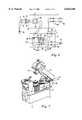
- FIG. 2is a perspective view of a preferred embodiment of the splitter module of the present invention interconnected with a POTS module;
- FIG. 3is an exploded view of a preferred embodiment of the splitter module of the present invention.
- FIG. 4is a side view of the preferred embodiment of the splitter module of the present invention being removed from its mounting location;
- FIG. 5is a side view of an alternative embodiment of the splitter module of the present invention being removed from its mounting location;
- FIG. 6is a wiring diagram of the preferred embodiment of the splitter module of the present invention interconnected with a POTS module;
- FIG. 7is an alternative embodiment of a POTS module with which a splitter module according to the present invention could also be used.
- NID 12network interface device 12
- NID 12has a plurality of POTS modules 14 removably mounted therein.
- Various types of NIDs with one or more POTS modulesare known in the art, and the present invention is not limited to a specific NID or POTS module design.
- the NID and POTS modules 14 depicted in FIG. 1are combined in a CAC 7600 available from Siecor Corporation.
- NID 12has housing 20 with interior 22 that is divided into subscriber compartment 24 and telephone company (telco) compartment 26.
- Inner door 28closes over telco compartment 26 and prevents removal of POTS modules 14 from NED 12.
- Outer door 30closes over inner door 28 and subscriber compartment 24, onto housing 20, and the subscriber is able to open outer door 30 to access subscriber compartment 24.
- Housing 20defines first port 32 entering into telco compartment 26.
- a plurality of protectors 34are mounted in telco compartment 26. Outside plant wire pairs 36 are routed into first port 32, through first grommet 38 and terminated at a respective pair of protector terminals 40 as is well known in the art.
- Each protector 34has a surge protector element that shorts to ground in response to a certain threshold surge over its respective outside plant wire pair 36.
- Ground terminals 42 of each protectorare connected together by wires 44, and the bottom ground terminal 42a is connected to earth ground wire 46 that is routed out of housing 12 to be joined to earth ground as is known.
- Other variations of how the protectors are arranged and connectedare common, including the PTD NID available from Siecor that houses the surge protector element in the POTS module.
- PTD patentsdisclose the structure and operation of the PTD NID and PTD POTS modules. Because the PTD POTS module contains the protector element, the outside plant wire pairs are routed directly to terminals on the PTD POTS module. In contrast, in FIG. 1, outside plant wire pairs 36 are connected to POTS modules 14 by being connected to protector terminals 40 to which leads 50 of POTS modules 14 are connected. Leads 50 of POTS modules 14 have outside plant terminals 52 which are connected to protector terminals 40 and thereby connected to outside plant wire pairs 36.
- Each POTS module 14is mounted in a respective mounting location 56b-d.
- Mounting locations 56a and 56fare empty and mounting location 56e receives splitter module 16 of the present invention as will be described in more detail below with reference to other Figures.
- Mounting locations 56have structure for removable mounting of POTS modules 14 thereto as will be discussed in further detail below.
- POTS moduleshave two pairs of subscriber terminals 60. Each pair has a ring terminal 62 and a tip terminal 64 and the ring terminals 62a, b are connected together by first conductor 66 and tip terminals 64a, b are connected together by second conductor 68.
- One subscriber ring terminal and one subscriber tip terminalmay be adequate, however, certain telephone companies require an extra pair of subscriber terminals.
- Inside wire pairs 72are connected to subscriber terminals 60 and routed outside of NID 12 through second grommet 74 and second port 76 as is well known.
- demarcation point 80Connected in series between outside plant terminals 52 and subscriber terminals 60 is demarcation point 80 which is shown as first jack 82 with first plug 84 inserted therein.
- First jack 82is wired to outside plant terminals 52 and first plug 84 is wired to subscriber terminals 60.
- first plug 84is disconnected from first jack 82, the inside wiring 72 is disconnected from the outside plant wiring.
- This demarcation pointserves at least two main purposes: (1) to provide a test point for the subscriber to determine whether a POTS signal malfunction is a result of something between the NID and the subscriber's phone or something beyond the NID such that it would be a telephone company problem, and (2) to remove the inside wiring from being in electrical contact with the outside plant wiring for safety concerns during repair or installation of inside wiring.
- First plug 84 and first jack 82are the commonly used RJ-11 telephone plug and jack where first plug has a free end for insertion into first jack 82 to make an electrical connection.
- First plug 84has a back end from which extends line cord 94.
- Line cord 94has first end 96 connected to first plug 84 and second end 98 opposite thereto and connected to subscriber terminals 60.
- Line cord 94is of sufficient length to allow first plug 84 to be removed from first jack 82 and placed out of the way to allow a test plug to then be inserted into first jack 82.
- the interface between first jack 82 and first plug 84is sealed in some manner, for example, by a boot 81 on the plug containing gel as disclosed in U.S. Pat. No. 5,595,504.
- POTS module 14'is shown which is a PTD module of the PTD patents referenced above.
- POTS module 14'has first plug 84' contained in door 85 that is hinged to POTS module 14'. When door 85 is closed, first plug 84' resides in first jack 82', and when door 85 is opened a test plug can then be inserted into first jack 82'.
- Line cord 94'has a first end connected to the back of the first plug and a second end connected to subscriber terminals 60'.
- the first plugis not readily separable from door 85; however, door 85 is readily snapped off of POTS module 14' at hooks 87.
- subscriber bridge 70is snap fit to POTS module 14' and is readily removable as shown in the PTD patents as a unit comprising subscriber terminals 60', door 85 and line cord 94'.
- First jack 82'remains on POTS module 14'.
- demarcation pointis known, such as having a jack and shunt plug arrangement where the subscriber terminals are wired to other contacts in the jack, and the plug shunts the outside plant contacts to the subscriber contacts.
- Another alternativeis a design where the demarcation point is out of circuit during normal operation and then physically switched into the circuit when needed, for example, U.S. Pat. No. 5,414,765.
- a common NID designis to locate the POTS modules in subscriber compartment 24 so that demarcation point 80 is accessible but have inner door 28 prevent removal of POTS modules 14 when inner door is closed. Also, inner door 28 covers protectors 34 to prevent access to the protectors by subscribers. Inner door 28 typically can only be opened by a special tool that subscribers do not typically possess thereby effectively preventing subscriber removal of the POTS modules and preventing access to telco compartment 26.
- the other commonly used NIDshave other door arrangements to similarly prevent removal of a line module from the NID while still providing access to the test jack on the line module.
- Each mounting location 56 of NID 12has vertical walls 100a-d. Walls 100a and 100b are opposite each other and have projection 102a, b respectively. Wall 100a has two vertical slots 104 on each side of projection 102a so as to define tang 106 which is slightly flexible.
- POTS module 14has first edge 58a and second edge 58b opposite thereto by a length approximately that between walls 100a and 100b such that edges 58a, b snap underneath projections 102a, b, respectively.
- Projection 102ahas ramp surface 103 along which edge 58a slides and flexes tang 106 outward. After edge 58a clears projection 102a, tang 106 flexes back to a vertical position such that projection 102a is disposed over edge 58a.
- Walls 100c,dhave ribs 108 on which POTS module 14 is disposed upon being snapped into mounting location 56.
- Inner door 28has free side 29 that is disposed adjacent tangs 106 when inner door 28 is closed so as to prevent tangs 106 from being flexed outward.
- Wall 100bis not flexible outward, therefore, edges 58a,b are confined underneath projections 102a,b, respectively when inner door 28 is closed. As such, when inner door 28 is closed and locked by a telco-access-only bolt or lock, POTS modules 14 are effectively locked in place such that a subscriber cannot remove them from NID 12.
- the present inventionprovides a splitter module that can be readily installed into NID 12 and interconnected with an existing POTS module 14, or an ISDN module or other module providing a demarcation point for a lower signal, so as to effectively locate an XDSL splitter physically in the NED and electrically between a first wire pair, e.g. an outside plant wire pair, and a second and third wire pair, e.g. two inside wiring pairs, to provide a demarcation point for one or more of the combined signal, lower signal and higher signal.
- a first wire paire.g. an outside plant wire pair
- a second and third wire paire.g. two inside wiring pairs
- housing 110that defines interior 112 that receives splitter circuit card 114 and is closed by cover 116 which has second jack 118 and second plug 120.
- Housing 110has generally five walls joined together to define interior 112: bottom wall 124, first end wall 126 and second end wall 128 opposite each other and extending generally perpendicular from bottom wall 124, top wall 130 opposite bottom wall 124 extending from first end wall 126 to second end wall 128, and side wall 132 spanning across these walls to close one side of the housing designated as closed side 134.
- Open side 136 of housing 110is opposite closed side 134.
- Periphery 138 of housing 110 around open side 136defines shoulder 140 recessed from edge 142
- Three projections 144extend from edge 142 over shoulder 140 so as to receive the edges of cover 116 snap fit therebetween.
- Bottom wall 124is sized to be received in a mounting location 56.
- First end wall 126has first ledge 146a for snapping underneath first projection 102a
- second end wall 128has second ledge 146b for being disposed underneath second projection 102b.
- second wall 128defines cut out 148 which creates flexible arm 150 with second ledge 146b. Arm 150 is deflectable into interior 112 by a finger until second ledge 146b clears second projection 102b allowing splitter module 16 to be slightly rotated and then lifted out of mounting location 56 even when inner door 28 is closed and locking POTS modules 14 in their respective mounting locations.
- First and second end walls 126, 128have recessed portions 152a, b, respectively, below ledges 146a, b, respectively, to prevent any interference between end walls 126, 128 and walls 100a,b, respectively, of mounting location 56 upon insertion and removal of splitter module 16 from mounting location 56.
- FIG. 5shows an alternative embodiment where splitter module 16' is not removable from mounting location 56 when inner door 28 is closed for the application where the telephone company owns the splitter module.
- Splitter module 16'has second end wall 128' that is continuous from the side wall to the open side at second ledge 146b' so that second ledge 146b' can not be deflected by a finger to clear second projection 102b.
- first end wall 126is continuous from the side wall to the open side at first ledge 146a so that it is not deflectable.
- Housing 110carries second terminals 158 which are shown as screws 160 that screw into screw posts 162 for connection of a wire as is known.
- second inside wire pair 72b for carrying the xDSL signal to the subscriberwould be terminated at terminals 158.
- Terminals 158may be any of a variety of designs, for example, insulation displacement connectors, post and washer, etc.
- Circuit card 114is mounted in housing 110.
- Circuit card 114has edge 166, first side 168 toward interior 112 and second side 170 opposite thereto.
- Edge 166corresponds at least partially with periphery 138 of housing 110 and housing 110 has ribs 172 with top surface 174 that receive edge 166 disposed thereon such that first side 168 of circuit card 114 is spaced from side wall 132.
- Circuit card 114can be secured within housing 110 by any suitable means, for example, by capturing it between top surface 174 and locating pins 177 on cover. Alternatively, circuit card can be secured by ultrasonic welding, screws, snap fit design, or other suitable means.
- circuit card 114carries xDSL splitter circuit 176 that comprises various splitter components 178 mounted on first side 168 so as to be located between side wall 132 and circuit card 114.
- First, second and third pair of contacts, 180, 182 and 184are located on second side 170 and connected through card 114 to circuit 176. Contacts 180, 182 and 184 may be any type of contact, for example, solder points, printed circuit board connectors, etc.
- Second plug 120is electrically connected to first pair of contacts 180 by second line cord 186 having first end 188 connected to second plug 120 and second end 190 opposite thereto connected to circuit 176 at first pair of contacts 180.
- Second plug 120is preferably an RJ-11 plug that is receivable in first jack 82 on POTS module 14.
- Second line 186 cordis of sufficient length to allow sufficient freedom of movement of second plug 120 to be inserted into first jack 82.
- Second jack 118is electrically connected to second pair of contacts 182 by leads 192.
- second jack 118may be electrically connected to circuit 176 with circuit board connectors.
- Second jack 118is preferably an RJ-11 jack that can receive first plug 84 inserted therein.
- Second jack 118is physically mounted to cover 116.
- Cover 116has edge 196 that generally corresponds to periphery 138 of housing 110 and that is snap fit between projections 144 and shoulder 140 to close interior 112 of housing 110.
- Cover 116defines well 198 with recessed surface 200 that defines opening 202 with notches 204.
- Latch fingers 194 of second jack 118snap through notches 204 to secure second jack 118 to recessed surface 200.
- Circuit card 114is shaped to accommodate well 198 extending past circuit card 114 into interior 112.
- Second jack 118has opening 206 that is approximately flush with cover 116 and oriented laterally. Second jack 118 is located such that when splitter module 16 is located adjacent a POTS module 14, opening 206 is accessible to receive first plug 84 therein. Alternatively, second jack 118 may be located where opening 206 is oriented upward, for example, by having second jack mounted on top wall 130. Cover 116 defines slot 208 through which second line cord 186 passes.
- splitter module 16With reference to FIGS. 2 and 6, the preferred interconnection of splitter module 16 with POTS module 14 is shown.
- POTS module 14is connected to the outside plant wire pair conventionally.
- the outside plant wire paircarries the combined signal.
- Splitter module 16is mounted adjacent to POTS module 14.
- First plug 84is removed from first jack 82 and inserted into second jack 118. This creates first demarcation point 210.
- Second plug 120is then inserted into first jack 82 which creates second demarcation point 214.
- First splitter circuit component 212for example a low pass filter, is connected in series between second jack 118 and second plug 120 and is designed to pass only the first signal, e.g. POTS, of a combined signal from second plug 120 to second jack 118.
- First pair of inside wires 72ais connected to subscriber terminals 60, or alternatively, these wires may already be connected to subscriber terminals 60 from the original POTS line installation and in such case they are simply left as connected.
- Second terminals 158are electrically connected to second plug 120 at third pair of contacts 184 at signal branch point 213 between low pass filter 212 and second plug 120 such that the entire combined signal travels to second terminals 158.
- Second pair of inside wires 72bis connected to second terminals 158.
- first demarcation point 210provides a test point for the isolated first signal, e.g. POTS
- second demarcation point 214provides a test point for the combined signal.
- first demarcation point 210By having first demarcation point 210, the traditional subscriber access point is retained for the subscriber to perform testing on a phone line as is the traditional use of a POTS demarcation point in NIDs. Second demarcation point is not suitable for such use because a phone plugged in to second demarcation point would most likely pick up other audible signals making it difficult to determine with certainty the location of a fault. However, second demarcation point 214 is also desirable because by disconnecting at this point removes both pairs of inside wires 72a, b from the outside plant for safety purposes. It also allows the xDSL modem to be plugged in to test for signals at that point.
- second splitter circuit component 218, for example a high pass filteris located in series between signal branch point 213 and second terminals 158 and is designed to pass only the second signal, e.g. xDSL signals, of a combined signal to second terminals 158.
- third jack 220 and third plug 222are added in series between second splitter circuit component 218 and second terminals 158 to provide third demarcation point 224 for the isolated second signal, e.g. xDSL.
- Third demarcation point 224may be desired to provide a test point for only the xDSL signal should there be some means for the subscriber to test for location of a fault with the xDSL signal that requires the absence of the POTS signal on the xDSL line.
- Second splitter circuit component 218may be any other component that exists or may be developed that selectively passes the higher signal. For example, a pair of DC blocking capacitors has been proposed as a possible substitute for a high pass filter.
- the housing of splitter module 16can be adapted to receive door 85 of a PTD POTS module 14' in view of the ease in which door 85 can be removed from the POTS module. If a replacement door is desired for POTS module 14', the second plug can be incorporated into a door that will then be replaced over the top of the POTS module.
- the housing of splitter module 16in view of the submodularity of subscriber bridge 70, can be adapted to receive the subscriber bridge from the POTS module which would include the door 85 and first plug 84'. The splitter module would then have second subscriber bridge to connect over the top of the POTS module.
- the interconnection of the present inventionis not limited to the exchanging of RJ-11 plugs and jacks between the modules but may be achieved by exchanging other detachable portions of the modules to achieve the same goal of incorporating the splitter circuit into the NID.
Landscapes
- Engineering & Computer Science (AREA)
- Computer Networks & Wireless Communication (AREA)
- Structure Of Telephone Exchanges (AREA)
Abstract
Description
Claims (20)
Priority Applications (2)
| Application Number | Priority Date | Filing Date | Title |
|---|---|---|---|
| US09/001,678US6026160A (en) | 1997-12-31 | 1997-12-31 | xDSL splitter interconnect module for network interface device |
| CA002256998ACA2256998C (en) | 1997-12-31 | 1998-12-23 | Xdsl splitter interconnect module for network interface device |
Applications Claiming Priority (1)
| Application Number | Priority Date | Filing Date | Title |
|---|---|---|---|
| US09/001,678US6026160A (en) | 1997-12-31 | 1997-12-31 | xDSL splitter interconnect module for network interface device |
Publications (1)
| Publication Number | Publication Date |
|---|---|
| US6026160Atrue US6026160A (en) | 2000-02-15 |
Family
ID=21697271
Family Applications (1)
| Application Number | Title | Priority Date | Filing Date |
|---|---|---|---|
| US09/001,678Expired - LifetimeUS6026160A (en) | 1997-12-31 | 1997-12-31 | xDSL splitter interconnect module for network interface device |
Country Status (2)
| Country | Link |
|---|---|
| US (1) | US6026160A (en) |
| CA (1) | CA2256998C (en) |
Cited By (35)
| Publication number | Priority date | Publication date | Assignee | Title |
|---|---|---|---|---|
| US6137866A (en)* | 1998-05-28 | 2000-10-24 | Siecor Operations, Llc | Indoor XDSL splitter assembly |
| US6239672B1 (en)* | 1998-06-29 | 2001-05-29 | Cisco Technology, Inc. | Wall mount filter for a digital subscriber line (xDSL) network and methods of installation and manufacture |
| US6272219B1 (en)* | 1998-04-01 | 2001-08-07 | Terayon Communications Systems, Inc. | Access network with an integrated splitter |
| US20030002660A1 (en)* | 2001-06-13 | 2003-01-02 | James Albanese | Network interface device and high speed delivery method therefor |
| US6570965B1 (en)* | 2000-11-02 | 2003-05-27 | Home Director, Inc. | Configurable telephone line distribution modules for designating primary and secondary telephone lines |
| WO2003056800A1 (en)* | 2001-12-26 | 2003-07-10 | Allied Telesis Kabushiki Kaisha | Vdsl system |
| US20030156389A1 (en)* | 2000-06-15 | 2003-08-21 | Ralf-Dieter Busse | Distributor module for use in telecommunications and data systems technology |
| WO2003101074A3 (en)* | 2002-05-23 | 2004-01-29 | 3M Innovative Properties Co | Cover plates for adsl-splitter positions in modular distribution frames |
| US6688919B2 (en)* | 2001-10-16 | 2004-02-10 | Adc Dsl Systems, Inc. | Housing for telecommunications module |
| US6711260B1 (en)* | 1998-08-18 | 2004-03-23 | Sbc Technology Resources, Inc. | Method and apparatus for spectral containment over telephone service lines |
| US20040251986A1 (en)* | 2001-10-22 | 2004-12-16 | Bernd Heise | Splitter circuit |
| US20050008142A1 (en)* | 2003-07-08 | 2005-01-13 | James Dickens | DSL protector having a detachable wire interface |
| US20050083959A1 (en)* | 2001-07-05 | 2005-04-21 | Serconet, Ltd. | Telephone outlet with packet telephony adapter, and a network using same |
| US6996232B1 (en)* | 1997-12-31 | 2006-02-07 | Corning Cable Systems Llc | XDSL splitter line module for network interface device |
| US20060072741A1 (en)* | 2003-01-30 | 2006-04-06 | Serconet Ltd | Method and system for providing DC power on local telephone lines |
| US20070041340A1 (en)* | 2003-09-07 | 2007-02-22 | Serconet Ltd. | Modular outlet |
| US20070047721A1 (en)* | 2005-08-26 | 2007-03-01 | Bryan Kennedy | Enclosure for broadband service delivery system |
| US20080013529A1 (en)* | 2000-04-18 | 2008-01-17 | Serconet Ltd. | Telephone communication system over a single telephone line |
| US20080205006A1 (en)* | 2003-08-08 | 2008-08-28 | Walter Fursich | Housing for Receiving Printed Circuit Boards Whose Components form at Least Parts of a Communication System |
| US20080226060A1 (en)* | 2004-02-16 | 2008-09-18 | Serconet Ltd. | Outlet add-on module |
| US20080292073A1 (en)* | 1999-07-20 | 2008-11-27 | Serconet, Ltd | Network for telephony and data communication |
| US20080304656A1 (en)* | 2007-06-08 | 2008-12-11 | Vernon Reed | Splitter wall plates for digital subscriber line (dsl) communication systems and methods to use the same |
| US7633966B2 (en) | 2000-04-19 | 2009-12-15 | Mosaid Technologies Incorporated | Network combining wired and non-wired segments |
| WO2010009408A1 (en)* | 2008-07-17 | 2010-01-21 | Afl Telecommunications, Llc | Method and apparatus for universal xdsl demarcation interface with multi-functional capability and signal performance enhancement |
| US7715534B2 (en) | 2000-03-20 | 2010-05-11 | Mosaid Technologies Incorporated | Telephone outlet for implementing a local area network over telephone lines and a local area network using such outlets |
| US7734037B1 (en)* | 2004-06-15 | 2010-06-08 | Verizon Services Corp. | Remote terminal unit connector |
| US7746905B2 (en) | 2003-03-13 | 2010-06-29 | Mosaid Technologies Incorporated | Private telephone network connected to more than one public network |
| US20110134937A1 (en)* | 2008-04-22 | 2011-06-09 | Afl Telecommunications ,Llc. | Method and apparatus for universal xdsl demarcation interface with multi-functional capability and signal performance enhancement |
| US7965735B2 (en) | 1998-07-28 | 2011-06-21 | Mosaid Technologies Incorporated | Local area network of serial intelligent cells |
| US7990908B2 (en) | 2002-11-13 | 2011-08-02 | Mosaid Technologies Incorporated | Addressable outlet, and a network using the same |
| US8582598B2 (en) | 1999-07-07 | 2013-11-12 | Mosaid Technologies Incorporated | Local area network for distributing data communication, sensing and control signals |
| EP2993881A1 (en)* | 2014-09-08 | 2016-03-09 | Nexans | Inner termination device |
| US10187515B2 (en)* | 2014-08-28 | 2019-01-22 | Corning Optical Communications LLC | Network interface devices having external demarcation points |
| US10230226B1 (en) | 2018-07-03 | 2019-03-12 | Afl Telecommunications Llc | Network interface devices |
| US10986164B2 (en) | 2004-01-13 | 2021-04-20 | May Patents Ltd. | Information device |
Citations (4)
| Publication number | Priority date | Publication date | Assignee | Title |
|---|---|---|---|---|
| US4910770A (en)* | 1986-06-30 | 1990-03-20 | Keptel, Inc. | Network interface device and enclosure |
| US5408260A (en)* | 1994-01-11 | 1995-04-18 | Northern Telecom Limited | Customer premises ADSL signal distribution arrangement |
| US5440335A (en)* | 1993-05-28 | 1995-08-08 | U S West Advanced Technologies, Inc. | Method and apparatus for delivering passband and telephony signals in a coaxial cable network |
| US5469495A (en)* | 1993-05-28 | 1995-11-21 | U S West Advanced Technologies, Inc. | Method and apparatus for delivering secured telephone service in hybrid coaxial cable network |
- 1997
- 1997-12-31USUS09/001,678patent/US6026160A/ennot_activeExpired - Lifetime
- 1998
- 1998-12-23CACA002256998Apatent/CA2256998C/ennot_activeExpired - Fee Related
Patent Citations (4)
| Publication number | Priority date | Publication date | Assignee | Title |
|---|---|---|---|---|
| US4910770A (en)* | 1986-06-30 | 1990-03-20 | Keptel, Inc. | Network interface device and enclosure |
| US5440335A (en)* | 1993-05-28 | 1995-08-08 | U S West Advanced Technologies, Inc. | Method and apparatus for delivering passband and telephony signals in a coaxial cable network |
| US5469495A (en)* | 1993-05-28 | 1995-11-21 | U S West Advanced Technologies, Inc. | Method and apparatus for delivering secured telephone service in hybrid coaxial cable network |
| US5408260A (en)* | 1994-01-11 | 1995-04-18 | Northern Telecom Limited | Customer premises ADSL signal distribution arrangement |
Non-Patent Citations (2)
| Title |
|---|
| A1000 ADSL Remote Splitter (LDFR) Installation (with Guidelines for In home Wiring); Alcatel Telecom; A9693; 3EC 15158 AAAA TCZZA Ed. 01, Dec. 1997.* |
| A1000 ADSL Remote Splitter (LDFR) Installation (with Guidelines for In-home Wiring); Alcatel Telecom; A9693; 3EC 15158 AAAA TCZZA-Ed. 01, Dec. 1997. |
Cited By (92)
| Publication number | Priority date | Publication date | Assignee | Title |
|---|---|---|---|---|
| US6996232B1 (en)* | 1997-12-31 | 2006-02-07 | Corning Cable Systems Llc | XDSL splitter line module for network interface device |
| US6272219B1 (en)* | 1998-04-01 | 2001-08-07 | Terayon Communications Systems, Inc. | Access network with an integrated splitter |
| US6137866A (en)* | 1998-05-28 | 2000-10-24 | Siecor Operations, Llc | Indoor XDSL splitter assembly |
| US6239672B1 (en)* | 1998-06-29 | 2001-05-29 | Cisco Technology, Inc. | Wall mount filter for a digital subscriber line (xDSL) network and methods of installation and manufacture |
| US8908673B2 (en) | 1998-07-28 | 2014-12-09 | Conversant Intellectual Property Management Incorporated | Local area network of serial intelligent cells |
| US7965735B2 (en) | 1998-07-28 | 2011-06-21 | Mosaid Technologies Incorporated | Local area network of serial intelligent cells |
| US7986708B2 (en) | 1998-07-28 | 2011-07-26 | Mosaid Technologies Incorporated | Local area network of serial intelligent cells |
| US8325636B2 (en) | 1998-07-28 | 2012-12-04 | Mosaid Technologies Incorporated | Local area network of serial intelligent cells |
| US8867523B2 (en) | 1998-07-28 | 2014-10-21 | Conversant Intellectual Property Management Incorporated | Local area network of serial intelligent cells |
| US8885659B2 (en) | 1998-07-28 | 2014-11-11 | Conversant Intellectual Property Management Incorporated | Local area network of serial intelligent cells |
| US8885660B2 (en) | 1998-07-28 | 2014-11-11 | Conversant Intellectual Property Management Incorporated | Local area network of serial intelligent cells |
| US8144852B2 (en) | 1998-08-18 | 2012-03-27 | At&T Labs, Inc. | Method and apparatus for spectral containment over telephone service lines |
| US20040120509A1 (en)* | 1998-08-18 | 2004-06-24 | Sbc Technology Resources, Inc. | Method and apparatus for spectral containment over telephone service lines |
| US6711260B1 (en)* | 1998-08-18 | 2004-03-23 | Sbc Technology Resources, Inc. | Method and apparatus for spectral containment over telephone service lines |
| US7020275B2 (en) | 1998-08-18 | 2006-03-28 | Sbc Technology Resources, Inc. | Method and apparatus for spectral containment over telephone service lines |
| US20060067488A1 (en)* | 1998-08-18 | 2006-03-30 | Sbc Technology Resources, Inc. | Method and apparatus for spectral containment over telephone service lines |
| US20080175364A1 (en)* | 1998-08-18 | 2008-07-24 | At&T Labs, Inc. | Method and apparatus for spectral containment over telephone service lines |
| US7352857B2 (en) | 1998-08-18 | 2008-04-01 | At&T Labs, Inc. | Method and apparatus for spectral containment over telephone service lines |
| US8582598B2 (en) | 1999-07-07 | 2013-11-12 | Mosaid Technologies Incorporated | Local area network for distributing data communication, sensing and control signals |
| US20080292073A1 (en)* | 1999-07-20 | 2008-11-27 | Serconet, Ltd | Network for telephony and data communication |
| US8929523B2 (en) | 1999-07-20 | 2015-01-06 | Conversant Intellectual Property Management Inc. | Network for telephony and data communication |
| US8351582B2 (en) | 1999-07-20 | 2013-01-08 | Mosaid Technologies Incorporated | Network for telephony and data communication |
| US8855277B2 (en) | 2000-03-20 | 2014-10-07 | Conversant Intellectual Property Managment Incorporated | Telephone outlet for implementing a local area network over telephone lines and a local area network using such outlets |
| US8363797B2 (en) | 2000-03-20 | 2013-01-29 | Mosaid Technologies Incorporated | Telephone outlet for implementing a local area network over telephone lines and a local area network using such outlets |
| US7715534B2 (en) | 2000-03-20 | 2010-05-11 | Mosaid Technologies Incorporated | Telephone outlet for implementing a local area network over telephone lines and a local area network using such outlets |
| US8000349B2 (en) | 2000-04-18 | 2011-08-16 | Mosaid Technologies Incorporated | Telephone communication system over a single telephone line |
| US8223800B2 (en) | 2000-04-18 | 2012-07-17 | Mosaid Technologies Incorporated | Telephone communication system over a single telephone line |
| US7593394B2 (en) | 2000-04-18 | 2009-09-22 | Mosaid Technologies Incorporated | Telephone communication system over a single telephone line |
| US20080013529A1 (en)* | 2000-04-18 | 2008-01-17 | Serconet Ltd. | Telephone communication system over a single telephone line |
| US8559422B2 (en) | 2000-04-18 | 2013-10-15 | Mosaid Technologies Incorporated | Telephone communication system over a single telephone line |
| US20080232579A1 (en)* | 2000-04-18 | 2008-09-25 | Serconet Ltd. | Telephone communication system over a single telephone line |
| US8873586B2 (en) | 2000-04-19 | 2014-10-28 | Conversant Intellectual Property Management Incorporated | Network combining wired and non-wired segments |
| US8867506B2 (en) | 2000-04-19 | 2014-10-21 | Conversant Intellectual Property Management Incorporated | Network combining wired and non-wired segments |
| US8848725B2 (en) | 2000-04-19 | 2014-09-30 | Conversant Intellectual Property Management Incorporated | Network combining wired and non-wired segments |
| US8982903B2 (en) | 2000-04-19 | 2015-03-17 | Conversant Intellectual Property Management Inc. | Network combining wired and non-wired segments |
| US7633966B2 (en) | 2000-04-19 | 2009-12-15 | Mosaid Technologies Incorporated | Network combining wired and non-wired segments |
| US8982904B2 (en) | 2000-04-19 | 2015-03-17 | Conversant Intellectual Property Management Inc. | Network combining wired and non-wired segments |
| US8873575B2 (en) | 2000-04-19 | 2014-10-28 | Conversant Intellectual Property Management Incorporated | Network combining wired and non-wired segments |
| US20030156389A1 (en)* | 2000-06-15 | 2003-08-21 | Ralf-Dieter Busse | Distributor module for use in telecommunications and data systems technology |
| US7410369B2 (en) | 2000-06-15 | 2008-08-12 | Adc Gmbh | Distribution connection module for telecommunications and data systems technology |
| US20090068893A1 (en)* | 2000-06-15 | 2009-03-12 | Adc Gmbh | Distribution connection module for telecommunications and data systems technology |
| US7270551B2 (en)* | 2000-06-15 | 2007-09-18 | Adc Gmbh | Distributor module for use in telecommunications and data systems technology |
| US7785115B2 (en) | 2000-06-15 | 2010-08-31 | Adc Gmbh | Distribution connection module for telecommunications and data systems technology |
| US6570965B1 (en)* | 2000-11-02 | 2003-05-27 | Home Director, Inc. | Configurable telephone line distribution modules for designating primary and secondary telephone lines |
| US20030002660A1 (en)* | 2001-06-13 | 2003-01-02 | James Albanese | Network interface device and high speed delivery method therefor |
| US7769030B2 (en) | 2001-07-05 | 2010-08-03 | Mosaid Technologies Incorporated | Telephone outlet with packet telephony adapter, and a network using same |
| US7680255B2 (en) | 2001-07-05 | 2010-03-16 | Mosaid Technologies Incorporated | Telephone outlet with packet telephony adaptor, and a network using same |
| US8761186B2 (en) | 2001-07-05 | 2014-06-24 | Conversant Intellectual Property Management Incorporated | Telephone outlet with packet telephony adapter, and a network using same |
| US20050083959A1 (en)* | 2001-07-05 | 2005-04-21 | Serconet, Ltd. | Telephone outlet with packet telephony adapter, and a network using same |
| US8472593B2 (en) | 2001-07-05 | 2013-06-25 | Mosaid Technologies Incorporated | Telephone outlet with packet telephony adaptor, and a network using same |
| US6688919B2 (en)* | 2001-10-16 | 2004-02-10 | Adc Dsl Systems, Inc. | Housing for telecommunications module |
| US20040251986A1 (en)* | 2001-10-22 | 2004-12-16 | Bernd Heise | Splitter circuit |
| DE10151949B4 (en)* | 2001-10-22 | 2011-08-11 | Lantiq Deutschland GmbH, 85579 | Splitter circuitry |
| US7388885B2 (en) | 2001-10-22 | 2008-06-17 | Infineon Technologies Ag | Splitter circuit |
| WO2003056800A1 (en)* | 2001-12-26 | 2003-07-10 | Allied Telesis Kabushiki Kaisha | Vdsl system |
| US20050023020A1 (en)* | 2002-05-23 | 2005-02-03 | Friedrich Denter | Cover plates for ADSL-splitter positions in modular distribution frames |
| WO2003101074A3 (en)* | 2002-05-23 | 2004-01-29 | 3M Innovative Properties Co | Cover plates for adsl-splitter positions in modular distribution frames |
| US7990908B2 (en) | 2002-11-13 | 2011-08-02 | Mosaid Technologies Incorporated | Addressable outlet, and a network using the same |
| US7702095B2 (en) | 2003-01-30 | 2010-04-20 | Mosaid Technologies Incorporated | Method and system for providing DC power on local telephone lines |
| US8107618B2 (en) | 2003-01-30 | 2012-01-31 | Mosaid Technologies Incorporated | Method and system for providing DC power on local telephone lines |
| US20060072741A1 (en)* | 2003-01-30 | 2006-04-06 | Serconet Ltd | Method and system for providing DC power on local telephone lines |
| US8787562B2 (en) | 2003-01-30 | 2014-07-22 | Conversant Intellectual Property Management Inc. | Method and system for providing DC power on local telephone lines |
| US7746905B2 (en) | 2003-03-13 | 2010-06-29 | Mosaid Technologies Incorporated | Private telephone network connected to more than one public network |
| US8238328B2 (en) | 2003-03-13 | 2012-08-07 | Mosaid Technologies Incorporated | Telephone system having multiple distinct sources and accessories therefor |
| US20050008142A1 (en)* | 2003-07-08 | 2005-01-13 | James Dickens | DSL protector having a detachable wire interface |
| US7280655B2 (en)* | 2003-07-08 | 2007-10-09 | At&T Bls Intellectual Property Inc. | DSL protector having a detachable wire interface |
| US20080205006A1 (en)* | 2003-08-08 | 2008-08-28 | Walter Fursich | Housing for Receiving Printed Circuit Boards Whose Components form at Least Parts of a Communication System |
| US7903429B2 (en)* | 2003-08-08 | 2011-03-08 | Siemens Aktiengesellschaft | Housing for receiving printed circuit boards whose components form at least parts of a communication system |
| US7686653B2 (en) | 2003-09-07 | 2010-03-30 | Mosaid Technologies Incorporated | Modular outlet |
| US20070041340A1 (en)* | 2003-09-07 | 2007-02-22 | Serconet Ltd. | Modular outlet |
| US11032353B2 (en) | 2004-01-13 | 2021-06-08 | May Patents Ltd. | Information device |
| US10986164B2 (en) | 2004-01-13 | 2021-04-20 | May Patents Ltd. | Information device |
| US20080226060A1 (en)* | 2004-02-16 | 2008-09-18 | Serconet Ltd. | Outlet add-on module |
| US8611528B2 (en) | 2004-02-16 | 2013-12-17 | Mosaid Technologies Incorporated | Outlet add-on module |
| US7734037B1 (en)* | 2004-06-15 | 2010-06-08 | Verizon Services Corp. | Remote terminal unit connector |
| US7643631B2 (en)* | 2005-08-26 | 2010-01-05 | Adc Telecommunications, Inc. | Enclosure for broadband service delivery system |
| US20070047721A1 (en)* | 2005-08-26 | 2007-03-01 | Bryan Kennedy | Enclosure for broadband service delivery system |
| US20080304656A1 (en)* | 2007-06-08 | 2008-12-11 | Vernon Reed | Splitter wall plates for digital subscriber line (dsl) communication systems and methods to use the same |
| US8422662B2 (en) | 2007-06-08 | 2013-04-16 | At&T Intellectual Property I, L.P. | Splitter wall plates for digital subscriber line (DSL) communication systems and methods to use the same |
| US8644493B2 (en) | 2007-06-08 | 2014-02-04 | At&T Intellectual Property I, L.P. | Splitter wall plates for digital subscriber line (DSL) communication systems and methods to use the same |
| US20100098059A1 (en)* | 2007-06-08 | 2010-04-22 | Vernon Reed | Splitter wall plates for digital subscriber line (dsl) communication systems and methods to use the same |
| US7657023B2 (en) | 2007-06-08 | 2010-02-02 | At&T Intellectual Property I, L.P. | Splitter wall plates for digital subscriber line (DSL) communication systems and methods to use the same |
| US9264786B2 (en)* | 2008-04-22 | 2016-02-16 | Afl Telecommunications Llc | Method and apparatus for universal XDSL demarcation interface with multi-functional capability and signal performance enhancement |
| US20110134937A1 (en)* | 2008-04-22 | 2011-06-09 | Afl Telecommunications ,Llc. | Method and apparatus for universal xdsl demarcation interface with multi-functional capability and signal performance enhancement |
| US8406413B2 (en)* | 2008-04-22 | 2013-03-26 | Afl Telecommunications Llc | Method and apparatus for universal xDSL demarcation interface with multi-functional capability and signal performance enhancement |
| US20110170579A1 (en)* | 2008-04-22 | 2011-07-14 | Afl Telecommunications, Llc | METHOD AND APPARATUS FOR UNIVERSAL xDSL DEMARCATION INTERFACE WITH MULTI-FUNCTIONAL CAPABILITY AND SIGNAL PERFORMANCE ENHANCEMENT |
| WO2010009408A1 (en)* | 2008-07-17 | 2010-01-21 | Afl Telecommunications, Llc | Method and apparatus for universal xdsl demarcation interface with multi-functional capability and signal performance enhancement |
| US10187515B2 (en)* | 2014-08-28 | 2019-01-22 | Corning Optical Communications LLC | Network interface devices having external demarcation points |
| EP2993881A1 (en)* | 2014-09-08 | 2016-03-09 | Nexans | Inner termination device |
| FR3025682A1 (en)* | 2014-09-08 | 2016-03-11 | Nexans | INTERNAL TERMINATION DEVICE |
| US10230226B1 (en) | 2018-07-03 | 2019-03-12 | Afl Telecommunications Llc | Network interface devices |
| US10389095B1 (en) | 2018-07-03 | 2019-08-20 | Afl Telecommunications Llc | Network interface devices |
Also Published As
| Publication number | Publication date |
|---|---|
| CA2256998C (en) | 2006-02-21 |
| CA2256998A1 (en) | 1999-06-30 |
Similar Documents
| Publication | Publication Date | Title |
|---|---|---|
| US6026160A (en) | xDSL splitter interconnect module for network interface device | |
| US6137866A (en) | Indoor XDSL splitter assembly | |
| US6438226B1 (en) | XDSL splitter assembly for main distribution frame | |
| US6078661A (en) | Modular network interface device | |
| AU2002343375B2 (en) | Front access DSX assembly | |
| US6996232B1 (en) | XDSL splitter line module for network interface device | |
| US4488008A (en) | Telephone network interface device | |
| US5901220A (en) | Network interface device | |
| US6560334B1 (en) | Telephone subscriber line module | |
| US6322375B1 (en) | Network interface device with circuit board architecture | |
| US5297199A (en) | Apparatus for connecting and disconnecting subscriber premises line and incoming telephone company line | |
| AU2002343375A1 (en) | Front access DSX assembly | |
| US6229890B1 (en) | Network interface device with automatic connector closure | |
| WO1992004793A1 (en) | Modular protected entrance terminal | |
| US6039578A (en) | Network interface device for line testing | |
| KR100530429B1 (en) | Improved interface cards for use in telecommunication networks | |
| EP1578144B1 (en) | Modular arrangement in the field of telecommunications | |
| US20080318479A1 (en) | Plug in the Field of Telecommunications, an Assembly Including a Telecommunications Module and a Plug, and a Method of Manufacturing a Plug | |
| EP1895783A1 (en) | A modular assembly including a splitter module and a switch/control module as well as line, POTS and DSL contacts. | |
| WO1997023021A1 (en) | Test port jack for network interface device | |
| WO2006022865A1 (en) | Termination module including subscriber bridge having burglar alarm connections | |
| US20030035535A1 (en) | Compact wall phone filter housing unit | |
| HK1065433B (en) | Front access dsx assembly |
Legal Events
| Date | Code | Title | Description |
|---|---|---|---|
| AS | Assignment | Owner name:SIECOR OPERATIONS, LLC, NORTH CAROLINA Free format text:ASSIGNMENT OF ASSIGNORS INTEREST;ASSIGNORS:STABER, HARLEY J.;LANDQUIST, TODD C.;KEENUM, JOHN A.;REEL/FRAME:009548/0319 Effective date:19980511 | |
| STCF | Information on status: patent grant | Free format text:PATENTED CASE | |
| FPAY | Fee payment | Year of fee payment:4 | |
| FPAY | Fee payment | Year of fee payment:8 | |
| FPAY | Fee payment | Year of fee payment:12 | |
| AS | Assignment | Owner name:CORNING CABLE SYSTEMS LLC, NORTH CAROLINA Free format text:CHANGE OF NAME;ASSIGNOR:SIECOR OPERATIONS, LLC;REEL/FRAME:041988/0926 Effective date:20000524 | |
| AS | Assignment | Owner name:CCS TECHNOLOGY, INC., DELAWARE Free format text:ASSIGNMENT OF ASSIGNORS INTEREST;ASSIGNOR:CORNING CABLE SYSTEMS LLC;REEL/FRAME:042377/0394 Effective date:20030124 | |
| AS | Assignment | Owner name:CORNING OPTICAL COMMUNICATIONS LLC, NORTH CAROLINA Free format text:MERGER;ASSIGNORS:CCS TECHNOLOGY, INC.;CORNING OPTICAL COMMUNICATIONS BRANDS, INC.;REEL/FRAME:043601/0427 Effective date:20170630 |