US6024759A - Method and apparatus for performing pectus excavatum repair - Google Patents
Method and apparatus for performing pectus excavatum repairDownload PDFInfo
- Publication number
- US6024759A US6024759AUS09/074,969US7496998AUS6024759AUS 6024759 AUS6024759 AUS 6024759AUS 7496998 AUS7496998 AUS 7496998AUS 6024759 AUS6024759 AUS 6024759A
- Authority
- US
- United States
- Prior art keywords
- pectus bar
- elongated
- pectus
- bar
- stabilizer
- Prior art date
- Legal status (The legal status is an assumption and is not a legal conclusion. Google has not performed a legal analysis and makes no representation as to the accuracy of the status listed.)
- Expired - Lifetime
Links
- 208000002325Funnel ChestDiseases0.000titleclaimsabstractdescription33
- 230000008439repair processEffects0.000titleclaimsabstractdescription33
- 206010034204Pectus excavatumDiseases0.000titleclaimsabstractdescription32
- 238000000034methodMethods0.000titleclaimsabstractdescription30
- 210000001562sternumAnatomy0.000claimsabstractdescription47
- 239000000463materialSubstances0.000claimsabstractdescription18
- 239000003381stabilizerSubstances0.000claimsdescription105
- 239000010935stainless steelSubstances0.000claimsdescription6
- 229910001220stainless steelInorganic materials0.000claimsdescription6
- 238000007493shaping processMethods0.000claimsdescription4
- 230000001186cumulative effectEffects0.000claims1
- 238000005452bendingMethods0.000description26
- 210000000779thoracic wallAnatomy0.000description13
- 238000001356surgical procedureMethods0.000description11
- 208000032170Congenital AbnormalitiesDiseases0.000description10
- 210000000038chestAnatomy0.000description9
- 210000000845cartilageAnatomy0.000description7
- 238000012360testing methodMethods0.000description7
- 230000008878couplingEffects0.000description6
- 238000010168coupling processMethods0.000description6
- 238000005859coupling reactionMethods0.000description6
- 230000007246mechanismEffects0.000description6
- 210000000115thoracic cavityAnatomy0.000description6
- QTCANKDTWWSCMR-UHFFFAOYSA-Ncostic aldehydeNatural productsC1CCC(=C)C2CC(C(=C)C=O)CCC21CQTCANKDTWWSCMR-UHFFFAOYSA-N0.000description5
- ISTFUJWTQAMRGA-UHFFFAOYSA-Niso-beta-costalNatural productsC1C(C(=C)C=O)CCC2(C)CCCC(C)=C21ISTFUJWTQAMRGA-UHFFFAOYSA-N0.000description5
- 238000002271resectionMethods0.000description4
- 238000006073displacement reactionMethods0.000description3
- 108700041400F 382Proteins0.000description2
- 239000000560biocompatible materialSubstances0.000description2
- 239000008280bloodSubstances0.000description2
- 210000004369bloodAnatomy0.000description2
- 210000000081body of the sternumAnatomy0.000description2
- 230000000694effectsEffects0.000description2
- 230000001747exhibiting effectEffects0.000description2
- 238000003780insertionMethods0.000description2
- 230000037431insertionEffects0.000description2
- 230000007774longtermEffects0.000description2
- 230000013011matingEffects0.000description2
- 210000001370mediastinumAnatomy0.000description2
- 210000003205muscleAnatomy0.000description2
- 210000002976pectoralis muscleAnatomy0.000description2
- 230000000717retained effectEffects0.000description2
- 235000020637scallopNutrition0.000description2
- 231100000241scarToxicity0.000description2
- RBMHUYBJIYNRLY-UHFFFAOYSA-N2-[(1-carboxy-1-hydroxyethyl)-hydroxyphosphoryl]-2-hydroxypropanoic acidChemical compoundOC(=O)C(O)(C)P(O)(=O)C(C)(O)C(O)=ORBMHUYBJIYNRLY-UHFFFAOYSA-N0.000description1
- 229910000684Cobalt-chromeInorganic materials0.000description1
- 206010010356Congenital anomalyDiseases0.000description1
- JVTAAEKCZFNVCJ-REOHCLBHSA-NL-lactic acidChemical compoundC[C@H](O)C(O)=OJVTAAEKCZFNVCJ-REOHCLBHSA-N0.000description1
- 208000001826Marfan syndromeDiseases0.000description1
- 241000237509Patinopecten sp.Species0.000description1
- 241000237503PectinidaeSpecies0.000description1
- 229920000954PolyglycolidePolymers0.000description1
- 208000026062Tissue diseaseDiseases0.000description1
- RTAQQCXQSZGOHL-UHFFFAOYSA-NTitaniumChemical compound[Ti]RTAQQCXQSZGOHL-UHFFFAOYSA-N0.000description1
- 230000003444anaesthetic effectEffects0.000description1
- 238000009412basement excavationMethods0.000description1
- 210000000988bone and boneAnatomy0.000description1
- 239000010952cobalt-chromeSubstances0.000description1
- 230000006835compressionEffects0.000description1
- 238000007906compressionMethods0.000description1
- 229920001577copolymerPolymers0.000description1
- 238000012937correctionMethods0.000description1
- 239000002537cosmeticSubstances0.000description1
- 230000000994depressogenic effectEffects0.000description1
- 238000005516engineering processMethods0.000description1
- OVBPIULPVIDEAO-LBPRGKRZSA-Nfolic acidChemical compoundC=1N=C2NC(N)=NC(=O)C2=NC=1CNC1=CC=C(C(=O)N[C@@H](CCC(O)=O)C(O)=O)C=C1OVBPIULPVIDEAO-LBPRGKRZSA-N0.000description1
- 239000007943implantSubstances0.000description1
- 238000002513implantationMethods0.000description1
- 208000014674injuryDiseases0.000description1
- 230000003601intercostal effectEffects0.000description1
- 210000004072lungAnatomy0.000description1
- 229910052751metalInorganic materials0.000description1
- 239000002184metalSubstances0.000description1
- 238000012986modificationMethods0.000description1
- 230000004048modificationEffects0.000description1
- 238000001885myotomyMethods0.000description1
- 229920001434poly(D-lactide)Polymers0.000description1
- 229920001432poly(L-lactide)Polymers0.000description1
- 229920000642polymerPolymers0.000description1
- 238000005070samplingMethods0.000description1
- 210000004872soft tissueAnatomy0.000description1
- 230000006641stabilisationEffects0.000description1
- 238000011105stabilizationMethods0.000description1
- 230000000087stabilizing effectEffects0.000description1
- 238000007655standard test methodMethods0.000description1
- 238000010998test methodMethods0.000description1
- 239000010936titaniumSubstances0.000description1
- 229910052719titaniumInorganic materials0.000description1
- 230000005532trappingEffects0.000description1
- 230000008733traumaEffects0.000description1
- 238000012800visualizationMethods0.000description1
- 238000003466weldingMethods0.000description1
Images


Classifications
- A—HUMAN NECESSITIES
- A61—MEDICAL OR VETERINARY SCIENCE; HYGIENE
- A61B—DIAGNOSIS; SURGERY; IDENTIFICATION
- A61B17/00—Surgical instruments, devices or methods
- A61B17/56—Surgical instruments or methods for treatment of bones or joints; Devices specially adapted therefor
- A61B17/58—Surgical instruments or methods for treatment of bones or joints; Devices specially adapted therefor for osteosynthesis, e.g. bone plates, screws or setting implements
- A61B17/88—Osteosynthesis instruments; Methods or means for implanting or extracting internal or external fixation devices
- A61B17/8863—Apparatus for shaping or cutting osteosynthesis equipment by medical personnel
- A—HUMAN NECESSITIES
- A61—MEDICAL OR VETERINARY SCIENCE; HYGIENE
- A61B—DIAGNOSIS; SURGERY; IDENTIFICATION
- A61B17/00—Surgical instruments, devices or methods
- A61B17/56—Surgical instruments or methods for treatment of bones or joints; Devices specially adapted therefor
- A61B17/58—Surgical instruments or methods for treatment of bones or joints; Devices specially adapted therefor for osteosynthesis, e.g. bone plates, screws or setting implements
- A61B17/68—Internal fixation devices, including fasteners and spinal fixators, even if a part thereof projects from the skin
- A61B17/80—Cortical plates, i.e. bone plates; Instruments for holding or positioning cortical plates, or for compressing bones attached to cortical plates
- A61B17/8061—Cortical plates, i.e. bone plates; Instruments for holding or positioning cortical plates, or for compressing bones attached to cortical plates specially adapted for particular bones
- A61B17/8076—Cortical plates, i.e. bone plates; Instruments for holding or positioning cortical plates, or for compressing bones attached to cortical plates specially adapted for particular bones for the ribs or the sternum
Definitions
- This inventionrelates generally to a method and apparatus for use in surgical procedures, and more particularly, to a method and apparatus for performing pectus excavatum repair.
- Pectus excavatumalso known as funnel chest
- Pectus excavatumis one of the most common anterior chest wall deformities. Patients exhibiting this deformity range from having a mildly depressed sternum to other extreme cases in which the sternum is positioned substantially adjacent to the vertebrae column.
- This depression or deformityis produced by posterior depression of the sternum and the lower costal cartilages.
- the body of the sternumis generally angled posteriorly towards the vertebrae generally starting below the second costal cartilage.
- the costal cartilagesare then angled posteriorly to meet the sternum, thereby creating a depression in the chest wall.
- This strutgenerally consists of an elongated rectangular shaped bar having a rectangular cross-section that can be bent manually to hold the sternum in a slightly over-corrected position.
- This strutis generally laid behind the lower half of the body of the sternum, with the separated sternum laid atop the strut.
- the strutis anchored on each side at the appropriate position to a rib exposed by a myotomy through the pectoral muscles. Holes positioned at each end of the strut are then used to facilitate fixation by means of sutures.
- This struthas a thickness of 1.5 mm, provides an estimated bendable strength of about 24 in-lbs (inch-pounds) and a bendable stiffness of about 232 lb-in 2 (pounds times inches squared), as estimated and determined in accordance with the procedure set forth in ASTM (American Standard Test Method) F382 and further discussed herein.
- This strutalso has an estimated yield strength of about 25 ⁇ 10 6 psi (pounds per square inch) based upon the material used for this strut.
- This strutfurther does not provide for stabilization of the strut ends by means other than fixation with sutures which is generally not sufficient in many adolescent patients and older or for Applicants' new procedure. Furthermore, the blunt or squared ends of this bar are also difficult to guide through a patient and may tear and catch on soft tissue.
- a method and apparatus for performing pectus excavatum repair on a deformed sternumis disclosed. This is basically achieved by providing an elongated bar having minimum bendable strength, a minimum bendable stiffness, or a minimum yield strength.
- the baris preferably bent in a convex manner and inserted with the convexity facing posteriorly and thereafter rotated with the convexity facing anteriorly.
- an apparatus for performing pectus excavatum repair on a deformed sternumincludes an elongated pectus bar.
- the elongated pectus barhas a first end and a second end with a minimum bendable strength of about 65 in-lbs.
- the elongated pectus baris operable to retrain the deformed sternum into a desired shape.
- an apparatus for performing pectus excavatum repair on a deformed sternumalso includes an elongated pectus bar.
- the elongated pectus barhas a first end and a second end with a minimum bendable stiffness of about 1000 lb-in 2 .
- the elongated pectus baris operable to retrain a deformed sternum into a desired shape.
- an apparatus for performing pectus excavatum repair on a deformed sternumalso includes an elongated pectus bar.
- the elongated pectus barhas a first end and a second end with a yield strength of at least about 35 ⁇ 10 6 psi.
- the elongated baris operable to retrain the deformed sternum into a desired shape.
- a method for performing pectus excavatum repair on a deformed sternumincludes the steps of providing an elongated pectus bar having a first end and a second end, shaping the pectus bar into a convexly curved pectus bar, passing the pectus bar under the deformed sternum with the convexity facing posteriorly, and rotating the pectus bar so that the convexity faces anteriorly, whereby the deformed sternum is raised into a desired position.
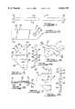
- FIG. 1is a top elevational view of a pectus bar for performing pectus excavatum repair according to the teachings of a first preferred embodiment of the present invention
- FIG. 1Ais a perspective view of a pectus bar for performing pectus excavatum repair according to the teachings of a second preferred embodiment of the present invention
- FIG. 1Bis a perspective view of a pectus bar for performing pectus excavatum repair according to the teachings of a third preferred embodiment of the present invention
- FIG. 1Cis a perspective view of a pectus bar for performing pectus excavatum repair according to the teachings of a fourth preferred embodiment of the present invention.
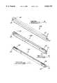
- FIG. 2is an enlarged top elevational view of the pectus bar of FIG. 1;
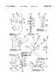
- FIG. 3is a top elevational view of a stabilizer for performing pectus excavatum repair according to the teachings of a first preferred embodiment of the present invention
- FIG. 4is a right side elevational view of the stabilizer of FIG. 3;
- FIG. 5is a perspective view of the pectus bar of FIG. 1 assembled with the stabilizer of FIG. 3;
- FIG. 6is a side cross-sectional view of the assembly of FIG. 5 taken along line 6--6 of FIG. 5;
- FIG. 7is a top elevational view of a stabilizer for performing pectus excavatum repair according to the teachings of a second preferred embodiment of the present invention.
- FIG. 8is a right side elevational view of the stabilizer of FIG. 7;
- FIG. 9is a top elevational view of a stabilizer for performing pectus excavatum repair according to the teachings of a third preferred embodiment of the present invention.
- FIG. 10is a left side elevational view of the stabilizer of FIG. 9;
- FIG. 11is a side elevational view of a rivet for performing pectus excavatum repair according to the teachings of the present invention.
- FIG. 12is a perspective view of the pectus bar of FIG. 1 assembled with the stabilizer of FIG. 9 and the rivet of FIG. 11;
- FIG. 13is a top elevational view of a stabilizer for performing pectus excavatum repair according to the teachings of a fourth preferred embodiment of the present invention.
- FIG. 14is a left side elevational view of the stabilizer of FIG. 13;
- FIG. 15is a top elevational view of a stabilizer for performing pectus excavatum repair according to the teachings of a fifth preferred embodiment of the present invention.
- FIG. 16is a left side elevational view of the stabilizer of FIG. 15;
- FIG. 17is an assembled side cross-sectional view of the stabilizer of FIG. 15 utilizing a pair of bolts to secure the stabilizer of FIG. 15 to the pectus bar of FIG. 1;
- FIG. 18is a top elevational view of a stabilizer for performing pectus excavatum repair according to the teachings of a sixth preferred embodiment of the present invention.
- FIG. 19is a right side elevational view of the stabilizer of FIG. 18;
- FIG. 20is a top elevational view of a stabilizer for performing pectus excavatum repair according to the teachings of a seventh preferred embodiment of the present invention.
- FIG. 21is a left side elevational view of the stabilizer of FIG. 20;
- FIG. 22is a top elevational view of a stabilizer for performing pectus excavatum repair according to the teachings of a eighth preferred embodiment of the present invention.
- FIG. 23is a right side elevational view of the stabilizer of FIG. 22.
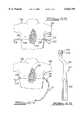
- FIGS. 24-32illustrate a method for performing pectus excavatum repair applying the pectus bar of FIG. 1, the stabilizer of FIG. 3 along with instrumentation used during the surgical procedure.
- pectus baras used herein may refer to a single pectus bar or multiple bars positioned or aligned adjacent one another to form the pectus bar with either the single pectus bar or the multiple bars combined providing at least the minimum bendable strength, bendable stiffness or yield strength, as further described herein.
- the pectus bar 10is an elongated bar having a lateral rectangular cross-section with a first end 12 and a second end 14.
- the pectus bar 10is provided in various sizes having a length between about 7 inches to about 15 inches with each size varying by about 1 inch.
- the thickness of the pectus bar 10preferably ranges between about 1.5 mm to about 4.5 mm and the width preferably varies between about 5 mm to about 20 mm. However, should there be additional clearance, the pectus bar 10 may be thicker or wider.
- the pectus bar 10includes a pair of opposing planar sidewalls 16 and 18 and a pair of opposing arcuate sidewalls 20 and 22.
- the second end 14 of the pectus bar 10is shown in an enlarged view with the understanding that the first end 12 is a mirror image of the second end 14.
- the second end 14includes the arcuate sidewall 22 which is generally a half circle.
- Each sidewall 16 and 18define a plurality of arcuate notches or scallops 24 having arcuate corners 26 to eliminate any sharp contours.
- Each sidewall 16 and 18includes five (5) notches 24, however, those skilled in the art would recognize that fewer or more notches may also be provided.
- the notches 24are essentially used for securing the pectus bar 10 by wrapping sutures about the notches 24.
- a hole 28 having a chamfer 30is defined by the pectus bar 10 and is perpendicular to a first planar surface 32 and opposing planar surface 34 (see FIG. 6).
- the hole 28may further be used for securing the pectus bar 10, via sutures passing therethrough or for securing the pectus bar 10 to a stabilizer, further discussed herein.
- the pectus bar 10is provided in a straight or flattened condition which is subsequently shaped to match a desired chest contour during surgery. As previously indicated, the pectus bar 10 has a thickness between the range of about 1.5 mm to about 4.5 mm. The width of the pectus bar 10 is between the range of about 5 mm to about 20 mm. In this regard, the cross-sectional area ranges between about 7.5 mm 2 to about 90 mm 2 with the thicker bars or larger cross-sectional area exhibiting a higher bending stiffness and bending strength.
- the minimum required bending strength and the minimum required bending stiffness needed to train and shape the sternumshould be about 65 in-lbs and 1000 lb-in 2 , respectively, as defined using ASTM Method F382-95.
- the material selectedshould have a minimum yield strength of about 35 ⁇ 10 6 psi. It should be noted that the minimum bending strength, bending stiffness, and yield strength are far in excess of that determined to be exhibited by the prior art Mueller bar. For example, upon testing six pectus bars 10, each having a thickness of 2.8 mm and a length of 13 inches with each made from cold-worked 316 LVM stainless steel, an average bending strength of 174 in-lbs and an average bending stiffness of 1283 lb-in 2 was determined.
- these pectus barsexhibit a yield strength of about 135 ⁇ 10 6 psi.
- the bending strengths and bending stiffnessesare based upon ASTM F382 test method set forth below which identifies the test materials, equipment, procedure and results.
- Sternum PlateSix (6) plates with a length of 13" and all plates made from 316 LVM stainless steel and each are 2.8 mm thick.
- Test FixtureFour point bend fixture with 3/8" diameter rollers at loading and support locations. The distance h and k, as defined in ASTM F382-95, were 1.5".
- Test MachineServo-hydraulic test machine from Interlaken Technology Corp. (Eden Prairie, Minn.). Machine was operated in displacement control at a rate of 0.50"/min. Load and displacement data was recorded at a sampling rate of 4 points/sec.
- Table 1summarizes the results from the test.
- the average bending strengthis 174 in-lbs.
- the average bending stiffness for the platesis 1283 lb-in 2 , as defined in ASTM F382-95.
- the pectus baris preferably made from cold-worked 316 LVM stainless steel to deliver the above desired bending strength and bending stiffness within the desired thickness and cross-sectional area ranges which are above the minimum bending strength and stiffness required. Moreover, the material selected for the pectus bar also provides a yield strength of 135 ⁇ 10 6 psi which is also above the minimum yield strength needed to reach a successful result. Those skilled in the art will also recognize that various other bio-compatible materials can also be utilized such as titanium, cobalt-chrome, etc.
- various resorbable material that can be shapedmay also be used for the pectus bar 10 as long as it provides the above-identified minimum bending strength, stiffness of the bar or yield strength within the desired thickness and cross-sectional area ranges.
- These resorbable materialsinclude, but are not limited to, any of a family of resorbable materials including polymers and copolymers of PLLA, PGA, PDLA, etc. or any of the resorbable materials set forth in U.S. Pat. No. 5,569,250 which is hereby incorporated by reference.
- each of the characteristics of bending strength, bending stiffness and yield strengthare independent from one another. Therefore, by providing a single pectus bar 10, which may include a plurality of adjacent bars, that meets any one of the minimum bending strength, bending stiffness or yield strength requirement from a single bar or accumulative from the multiple bars will enable successful treatment of this deformity.
- the increase in the bending strength, bending stiffness and yield strengthis also required to achieve the successful result, since the shape of the sternum is actually retrained to maintain a new desired shape without a sterno-osteotomy or cartilage resection as previously performed in the prior art using the prior art strut from the V. Mueller, as noted above.
- pectus bars 10A-10Care shown in alternate preferred embodiments.
- pectus bar 10Aincludes three (3) independent elongated cylindrical bars 11 which are positioned substantially adjacent to one another.
- the cylindrical bars 11may be linked together by any appropriate means, such as metal bands, welding, etc. or may merely be located adjacent one another independently.
- the pectus bar 10Bis shown including three (3) staggered elongated rectangular shaped bars 13 also aligned and positioned adjacent one another to form the single pectus bar 10B.
- the pectus bar 10Calso includes the three (3) elongated rectangular bars 13 stacked atop one another, as shown clearly in FIG. 1C.
- pectus bars 10A, 10B and 10Care employed substantially similar to the pectus bar 10 further described herein.
- pectus bars 10A, 10B and 10Cmay be affixed to the various embodiments of the stabilizers disclosed herein, may include arcuate or rounded ends, as well as include notches or bores for assisting in securing the pectus bars 10A, 10B and 10C within the patient, as described with respect to pectus bar 10. It should also be understood that the pectus bars 10A, 10B and 10C may be formed from more or less than the three (3) bars shown.
- the stabilizer 36is designed to be received on one or both ends 12 and 14 of the pectus bar 10 in order to stabilize the positioning and placement of the pectus bar 10 within a patient, further discussed herein.
- the stabilizer 36is also preferably constructed from cold-worked 316 LVM stainless steel or any other biocompatible material as set forth above, including any resorbable material, such as Lactosorb provided by Biomet, Inc. of Warsaw, Ind.
- the stabilizer 36has a first planar surface 38, a second planar surface 40 and is defined by a substantially triangular shaped sidewall 42 having rounded corners 44.
- the sidewall 42defines two sets of three notches 46, each again used for retaining the stabilizer 36, via sutures wrapped about the notches 46.
- a dove tail groove or channel 48runs from a first rounded corner 50 to a center 52 of a side 54.
- the channel 48is defined by a first planar sidewall 56, opposing perpendicular sidewalls 58 and inner sidewalls 60 of flange 62.
- the mating shapecould be triangular or any shape that allows mating of the components.
- the slot or channel 48is operable to slidably receive either end 12 or 14 of the pectus bar 10.
- the stabilizer plate 36also defines a pair of holes or bores 64 defined by a sidewall 66.
- the stabilizer 36is shown slidably received within the pectus bar 10.
- the second end 14 of the pectus bar 10is shown having an arcuate shape to meet the contour of the chest cavity.
- the sidewalls 58 of the channel 48provide for a clearance of the curved pectus bar 10, as shown in FIG. 6.
- This curvature of the pectus bar 10is used to snuggly secure the pectus bar 10 relative to the stabilizer 36 along substantially three contact points 68.
- the stabilizer 36will generally be sutured on both the first end 12 and the second end 14 of the pectus bar 10 to ensure that the pectus bar 10 is fixedly retained within the chest cavity upon implantation.
- FIGS. 7-8a stabilizer 70 according to the teachings of a second preferred embodiment in the present invention, is shown.
- the stabilizer 70is substantially similar to the stabilizer 36, except for defining a first channel 72 and a second channel 74 along with defining a centrally positioned hole 76 and three notches 78 positioned adjacent thereto.
- the hole 76is defined by the sidewall 66 and the notches 78 are used to receive sutures for securing the stabilizer 70 relative to the chest cavity.
- the first channel 72 and the second channel 74allow for a pair of pectus bars 10 to be joined substantially parallel to one another to provide even further contouring and shaping capabilities which may be required for more severe deformities.
- the channels 72 and 74are also operable to slidably receive pectus bars 10 and the contour of the pectus bars 10 are operable to snuggly secure the pectus bars 10 relative to the stabilizer 70.
- FIGS. 9-12a stabilizer 80 according to the teachings of a third preferred embodiment of the present invention, is shown.
- the stabilizer 80is substantially similar to the stabilizer 36 except that the stabilizer 80 defines a channel 82 having a rounded closed end 84 with a hole 86 defined by sidewall 66 positioned adjacent thereto.
- each side of the triangular shaped sidewall 42includes a set of three notches 88.
- the endwall 84 along with the hole 86is substantially aligned with the hole 28 and each end 12 and 14 of the pectus bars 10.
- a rivet 90is operable to be passed through both holes 28 and 86 of the pectus bar 10 and stabilizer 80, respectively, to fixedly secure the stabilizer 80 relative to the pectus bar 10.
- the rivet 90as shown in FIG. 11, includes an arcuate shaped head 92, a cylindrical shaft portion 94 and a conically shaped locking portion 96. Passing through the cylindrical shaft 94 and the conically shaped portion 96 is a U-shaped groove 98 which enables the rivet 90 to flex upon passing the rivet 90 through holes 28 and 86.
- various other coupling elements or mechanismssuch as a nut and bolt, machine screw, etc. could also be used to secure the stabilizer 80 relative to the pectus bar 10.
- FIG. 12shows the stabilizer 80 secured to the second end 14 of the pectus bar 10 with the rivet 90.
- the stabilizer 100is substantially similar to the stabilizer 80 except that the stabilizer 100 includes a channel 102 defined by a first planar sidewall 104 and opposing perpendicular sidewalls 106 having a rounded end 108.
- the channel 102does not include the upturned flange 62, which thereby provides further versatility with regard to attaching and aligning the stabilizer 100 relative to the pectus bar 10.
- the channel 102further includes a pair of holes 110 defined by sidewalls 66 which are designed to mate with a pair of holes 28 passing through each end 12 and 14 of the pectus bar 10.
- the two holes 110are designed to operably receive the rivets 90 or other appropriate coupling mechanisms.
- the two holes 110provide further securement of the stabilizer 10 relative to the pectus bar 10 since there is generally no three point contact 68 used with the stabilizer 100.
- the pectus bar 10is generally not contoured along this area and remains substantially planar for hole alignment.
- the stabilizer 112includes a first planar surface 114, a second planar surface 116 with a substantially rectangular shaped sidewall 118 having rounded ends 120.
- the stabilizer 112includes a pair of holes 122 defined by sidewalls 124 and a dove tail channel 126.
- the channel 126is defined by a first planar sidewall 128, opposing perpendicular sidewalls 130 and flange sidewalls 132 of flange 134.
- the sidewalls 132are made to slidably receive the pectus bar 10 being shaped to have an arcuate contour.
- the pectus bar 10may be secured to the stabilizer 112 by way of a rivet 90 passing through a hole (not shown) centered within the channel 126 or by way of the arcuate contour formed within the pectus bar 10.
- a rivet 90passing through a hole (not shown) centered within the channel 126 or by way of the arcuate contour formed within the pectus bar 10.
- the stabilizer 112is primarily to prevent the pectus bar 10 from rotating 180° which is prevented by the flange 134, slight axial movement of the stabilizer 112 relative to the longitudinal axis of the pectus bar 10 may be tolerated.
- the stabilizer 112can be secured relative to the pectus bar 10 by way of wrapping sutures about both the stabilizer 112 and the pectus bar 10 to provide sufficient securement of the stabilizer 112 along the longitudinal axis of the pectus bar 10.
- the pectus bar 10may be secured to the stabilizer 112 by way of a pair of bolts 136 passing through holes 122 adjacent the flange 134, as shown in FIG. 17.
- the screw shaft 140may be captured by a notch or scallop 24 of the pectus bar 10.
- the rivet 90 or other coupling mechanismmay also be used.
- the stabilizer 144has an outer shape substantially similar to the stabilizer 112 and in this regard, like reference numerals will be used to identify like structures.
- the stabilizer 144includes a pair of channels 146 adapted to receive a pair of pectus bars 10 which will be positioned substantially parallel with one another.
- Each channel 146is defined by a planar sidewall 148 and a pair of perpendicular opposing sidewalls 150. Passing through each channel is a bore 152 defined by a sidewall 154 and passing through the center of the stabilizer 144 is a bore 156 defined by sidewall 158.
- the bores 152are operable to be aligned with the bore 28 in the first end 12 or the second end 14 of the pectus bar 10.
- the rivet 90 or other appropriate coupling mechanismcan then be used to secure the stabilizer 144 relative to the pectus bars 10.
- the bore 156is again used to receive sutures to provide further securement.
- the distance between each channel 146is generally determined by the distance between the patient's ribs.
- the stabilizer 160is pivotably coupled to a pectus bar 162, via a nut and bolt 164 or other coupling mechanism passing through bores 166 and 168, respectively.
- the pectus bar 162is substantially similar to the pectus bar 10, except that the end 170 of the pectus bar 162 includes a step 172 to define a clearance area 173 to retain a portion of the stabilizer 160.
- the stabilizer 160has a shape which is substantially similar to the stabilizer 112 except that no channel or slot is provided.
- the stabilizer 160is rotatably or pivotably secured to the pectus bar 162 such that upon insertion of the pectus bar 162 into the chest cavity, the stabilizer 160 is rotated about 90° clockwise or counter-clockwise to create a T-shaped end.
- a stabilizer 176according to the teachings of an eighth preferred embodiment of the present invention, is shown.
- the stabilizer 176is pivotably secured relative to a pectus bar 178.
- the pectus bar 178is substantially similar to the pectus bar 10, except that each end 180 of the pectus bar 178 includes or defines a U-shaped slot 182 which is operable to retain a portion of the stabilizer 176.
- the stabilizer 176is pivotably secured to the pectus bar 178, via a compression rivet 184 or other appropriate coupling element which passes through bore 186 of the pectus bar 178 and bore 188 within the stabilizer 176.
- the stabilizer 176can be rotated about 90° either clockwise or counter-clockwise to create a substantially T-shaped stabilizing mechanism.
- a patient's chest 190is measured prior to surgery with the correctly sized pectus bar 10 selected based upon the patient's chest size and overall concave deformity, identified by reference numeral 192.
- the size and strength of the pectus bar 10 selectedmust be strong enough to support the chest 190 in the corrected position even when the patient sustains unexpected trauma.
- the pectus bar 10remains within the patient for about a two-year period and thus needs to be long enough to accommodate for growth during this two-year period since the majority of the patients are small children.
- Two pectus bars 10are generally more effective than a single pectus bar 10, but in some situations may cause over-correction in some patients.
- Patients with Marfan's syndrome or other related tissue diseasesgenerally have soft bone and, therefore, require two pectus bars 10 in order to distribute the pressure over a wider area.
- a higher bendable strength and bendable stiffness pectus bar 10is required versus a patient having a less severe deformity 192 or a younger patient since the sternum is more malleable with the younger patient.
- the material utilized for the pectus bar 10is a cold-worked 316 LVM stainless steel which is capable of providing the minimal bendable strength, bendable stiffnesses or yield strength.
- the selected pectus bar 10is bent into an initial convex shape prior to surgery.
- a patientis positioned with both arms 194 abducted at the shoulder 196 to allow access to the lateral chest wall 190.
- the previously selected pectus bar 10is then placed on the patients chest 190 and bent into its final desired shape to conform to the desired anterior chest wall curvature.
- the pectus bar 10is custom bent into this desired shape by using a pectus bar bender 198, as shown in FIG. 24.
- the pectus bar bender 198includes a pair of handles 200, which pivot about a contour wheel 202 under spring tension from spring 204.
- a pair of rollers 206are used for shaping the pectus bar 10 against the contour wheel 202 upon drawing the handles 200 together.
- the pectus bar 10is positioned substantially perpendicular to the bender 198 between the rollers 206 and the contour wheel 202. In this way, the surgeon can easily shape the pectus bar 10 to any desired curvature upon placing the pectus bar 10 between the rollers 206 and the contour wheel 202 and squeezing the handles 200, as shown in FIG. 24.
- a transverse incision 208 of about 2.5 cm longis made on each side of the lateral chest wall 190 between the anterior axillary and posterior axillary lines, as shown in FIG. 26.
- a pectus bar umbilical tape puller 210as shown in FIG. 25 is then used to shape a tunnel under and adjacent to the sternum and to draw an umbilical tape 212 through a tunnel 214 formed by the puller 210.
- the excavation of the tunnelmay be facilitated by insertion of a thoracoscope into the chest to allow visualization of the tape puller as it comes through the mediastinum.
- the pectus bar umbilical tape puller 210has a substantially cylindrical body 216 which forms a handle 218 at the proximal end and a curved blunt tip 220 at the distal end. As the body 216 extends to the curved distal tip 220, the diameter of the cylindrical body 216 tapers to a smaller diameter. At the curved distal tip 220 there is defined a umbilical tape hole 222 which is operable to receive the umbilical tape 212. It should further be noted that a conventional Kelly clamp may also be used in place of the umbilical tape puller 210 and used in substantially the same way as described herein.
- the skin tunnel 214is raised anteriorly and the previously selected intercostal space is entered with the umbilical tape puller 210.
- the puller 210is slowly advanced across the mediastinum immediately under the sternum until it is emerged on the opposite side, as shown in FIG. 26.
- the umbilical tape 212is then passed through the hole 222 and through the tunnel 214. Once the strand of umbilical tape 212 is passed through the tunnel 214, the umbilical tape 212 may then be used to guide the puller 210 or the Kelly clamp from the opposite side to make sure that the tunnel 214 is wide enough to receive the pectus bar 10.
- the umbilical tape 212is again routed through the tunnel 214 and the pectus bar 10 is secured to one end of the umbilical tape 212 through hole 28 in the pectus bar 10, as shown in FIG. 27.
- the pectus bar 10is pulled beneath the sternum using the umbilical tape 212 for guiding and traction.
- the pectus bar 10is passed under the sternum with the convexity facing posteriorly and the rounded ends 12 and 14 self-guiding the pectus bar 10, as shown in FIG. 30.
- the pectus bar 10With the pectus bar 10 in position, the pectus bar 10 is turned over about 180° so that the convexity faces anteriorly, thereby raising the sternum 224 and anterior chest wall 190 into the desired position, as shown in FIGS. 30 and 31.
- the pectus bar 10is turned or rotated using a pectus bar flipper 226, as shown in FIG. 28.
- the pectus bar flipper 226includes a handle 228, a shaft 230 and an engagement head 232.
- the shaft 230is appropriately bent such that when the engagement head 232 is engaged with the pectus bar 10, the flipper 226 is positioned substantially away from the chest cavity 190.
- the engagement head 232defines a receiving slot 234 which is operable to slidably receive either the first end 12 or the second end 14 of the pectus bar 10. It should further be noted that in place of the flipper 226, a vice grip or other appropriate instrument may also be used to rotate the pectus bar 10.
- a second pectus bar 10may be placed superiorly or inferiorly, if required.
- the pectus bar 10may then be secured to the lateral chest wall muscles with heavy sutures 236.
- one of the above-identified stabilizersmay be attached to one or both ends of the pectus bar 10. If two pectus bars 10 are used, the stabilizers which are operable to receive a pair of pectus bars 10 are connected to both ends to substantially form a rectangular cage. As shown in FIG. 32, using the stabilizers 36, the stabilizers 36 are slid onto the first end 12 and the second end 14 of the pectus bar 10. The stabilizers 36, as well as the pectus bar 10, are then secured with the heavy sutures 236 to the lateral chest wall muscles.
- PEEPpositive end expiratory pressure
- the implantswould be resorbed over time without the need for subsequent removal. If a resorbable material is not used, the pectus bar 10 along with the stabilizers are removed after about two years on an outpatient basis.
- the chest wall deformity 192is thus substantially eliminated with the sternum 224 retaining substantially all of its new contoured shape.
Landscapes
- Health & Medical Sciences (AREA)
- Orthopedic Medicine & Surgery (AREA)
- Surgery (AREA)
- Life Sciences & Earth Sciences (AREA)
- Heart & Thoracic Surgery (AREA)
- Nuclear Medicine, Radiotherapy & Molecular Imaging (AREA)
- Engineering & Computer Science (AREA)
- Biomedical Technology (AREA)
- Medical Informatics (AREA)
- Molecular Biology (AREA)
- Animal Behavior & Ethology (AREA)
- General Health & Medical Sciences (AREA)
- Public Health (AREA)
- Veterinary Medicine (AREA)
- Neurology (AREA)
- Materials For Medical Uses (AREA)
Abstract
Description
TABLE 1 ______________________________________ Results Equiv. Bending Load, Slope, Stiffness, Bending Specimen P S E Strength # (lbs) (lb/in) (lb-in.sup.2) (in-lb) ______________________________________ Specimen 1 235 928 1305.0 176.3Specimen 2 228 904 1271.3 171.0Specimen 3 236 925 1300.8 177.0 Specimen 4 238 940 1321.9 178.5Specimen 5 219 880 1237.5 164.3 Specimen 6 232 896 1260.0 174.0 Average 231 912 1283 174 ______________________________________
Claims (33)
Priority Applications (1)
| Application Number | Priority Date | Filing Date | Title |
|---|---|---|---|
| US09/074,969US6024759A (en) | 1998-05-08 | 1998-05-08 | Method and apparatus for performing pectus excavatum repair |
Applications Claiming Priority (1)
| Application Number | Priority Date | Filing Date | Title |
|---|---|---|---|
| US09/074,969US6024759A (en) | 1998-05-08 | 1998-05-08 | Method and apparatus for performing pectus excavatum repair |
Publications (1)
| Publication Number | Publication Date |
|---|---|
| US6024759Atrue US6024759A (en) | 2000-02-15 |
Family
ID=22122737
Family Applications (1)
| Application Number | Title | Priority Date | Filing Date |
|---|---|---|---|
| US09/074,969Expired - LifetimeUS6024759A (en) | 1998-05-08 | 1998-05-08 | Method and apparatus for performing pectus excavatum repair |
Country Status (1)
| Country | Link |
|---|---|
| US (1) | US6024759A (en) |
Cited By (53)
| Publication number | Priority date | Publication date | Assignee | Title |
|---|---|---|---|---|
| US6569166B2 (en)* | 1999-10-20 | 2003-05-27 | Spiration, Inc. | Method for expanding the thorax |
| WO2004028412A1 (en)* | 2002-09-28 | 2004-04-08 | Medixalign Co., Ltd. | Implant for correction of pectus excavatum |
| US20040117016A1 (en)* | 2002-11-06 | 2004-06-17 | Horacio Abramson | Apparatus for the correction of chest wall deformities such as pectus carinatum and method of using the same |
| US20040243229A1 (en)* | 2002-01-09 | 2004-12-02 | Myocor, Inc. | Devices and methods for heart valve treatment |
| WO2005055844A1 (en) | 2003-12-12 | 2005-06-23 | Alexander Rokitansky | Implant for correction of cobbler's chest |
| US20060074448A1 (en)* | 2004-09-29 | 2006-04-06 | The Regents Of The University Of California | Apparatus and methods for magnetic alteration of deformities |
| US20060079897A1 (en)* | 2004-09-29 | 2006-04-13 | Harrison Michael R | Apparatus and methods for magnetic alteration of anatomical features |
| US20060259141A1 (en)* | 2005-05-13 | 2006-11-16 | Walter Lorenz Surgical, Inc. | Pectus bar stabilizer |
| US20060271107A1 (en)* | 2004-09-29 | 2006-11-30 | Harrison Michael R | Apparatus and methods for magnetic alteration of anatomical features |
| US20070276378A1 (en)* | 2004-09-29 | 2007-11-29 | The Regents Of The University Of California | Apparatus and methods for magnetic alteration of anatomical features |
| WO2008114915A1 (en)* | 2007-03-19 | 2008-09-25 | Hyung Joo Park | Introducer with dissection function for pectus excavatum repair operation |
| US20090048618A1 (en)* | 2004-09-29 | 2009-02-19 | The Regents Of The University Of California | Apparatus and method for magnetic alteration of anatomical features |
| US20090048601A1 (en)* | 2007-08-15 | 2009-02-19 | Forton Charles R | Mis crosslink apparatus and methods for spinal implant |
| WO2009035358A1 (en)* | 2007-09-13 | 2009-03-19 | Universidade Do Minho | System for automatic and personalized modelling/bending of surgical prosthesis for correction of pectus excavatum based on pre-surgical imaging information |
| WO2009028836A3 (en)* | 2007-08-28 | 2009-05-07 | Hyung Joo Park | Fixator for bar of pectus excavatum repair operation |
| US20100114103A1 (en)* | 2008-11-06 | 2010-05-06 | The Regents Of The University Of California | Apparatus and methods for alteration of anatomical features |
| RU2398540C1 (en)* | 2009-06-04 | 2010-09-10 | Общество с ограниченной ответственностью "ИЛЬКОМ" | Device for thoracoplasty on non-resected sternum deformed in funnel-shaped way and method of its realisation |
| US20110172576A1 (en)* | 2010-01-08 | 2011-07-14 | Alejandro Castro | Method and apparatus for nonsurgical correction of chest wall deformities |
| US20110208255A1 (en)* | 2010-02-23 | 2011-08-25 | Chi Mei Medical Center | Introducer device for use in nuss procedure |
| US20110203581A1 (en)* | 2001-10-25 | 2011-08-25 | Spiration, Inc. | Apparatus and method for deployment of a bronchial obstruction device |
| US20110251540A1 (en)* | 2010-04-13 | 2011-10-13 | David Notrica | Apparatus and method for treating pectus excavatum |
| CN102342855A (en)* | 2010-07-29 | 2012-02-08 | 财团法人奇美医院 | Introductory device for chest cavity correction |
| US20120130371A1 (en)* | 2009-08-14 | 2012-05-24 | Xinhua Hospital Affiliated To Shanghai Jiaotong University School Of Medicine | Steel plate for funnel chest orthopaedic surgery |
| US8221421B2 (en) | 2001-02-23 | 2012-07-17 | Synthes Usa, Llc | Sternum fixation device |
| US8328807B2 (en) | 2008-07-09 | 2012-12-11 | Icon Orthopaedic Concepts, Llc | Ankle arthrodesis nail and outrigger assembly |
| US20130023919A1 (en)* | 2004-11-19 | 2013-01-24 | Pulmonx, Inc. | Implant loading device and system |
| US8414584B2 (en) | 2008-07-09 | 2013-04-09 | Icon Orthopaedic Concepts, Llc | Ankle arthrodesis nail and outrigger assembly |
| RU2485903C1 (en)* | 2012-03-16 | 2013-06-27 | государственное бюджетное образовательное учреждение высшего профессионального образования "Башкирский государственный медицинский университет" Министерства здравоохранения Российской Федерации (ГБОУ ВПО БГМУ Минздрава России) | Device for treating funnel chest deformation |
| US8603127B2 (en) | 2002-03-20 | 2013-12-10 | Spiration, Inc. | Removable anchored lung volume reduction devices and methods |
| US8667973B2 (en) | 2003-04-08 | 2014-03-11 | Spiration, Inc. | Bronchoscopic lung volume reduction method |
| US20140163691A1 (en)* | 2011-05-23 | 2014-06-12 | Philippe Dartevelle | Osteosynthesis implant |
| US8795241B2 (en) | 2011-05-13 | 2014-08-05 | Spiration, Inc. | Deployment catheter |
| US8956319B2 (en) | 2002-05-17 | 2015-02-17 | Spiration, Inc. | One-way valve devices for anchored implantation in a lung |
| US8974484B2 (en) | 2001-09-11 | 2015-03-10 | Spiration, Inc. | Removable lung reduction devices, systems, and methods |
| US8974527B2 (en) | 2003-08-08 | 2015-03-10 | Spiration, Inc. | Bronchoscopic repair of air leaks in a lung |
| US20150134009A1 (en)* | 2013-11-14 | 2015-05-14 | Biomet Microfixation, Llc | Locking mechanism for pectus bar |
| US9198669B2 (en) | 2006-03-31 | 2015-12-01 | Spiration, Inc. | Articulable anchor |
| US20170156759A1 (en)* | 2015-08-05 | 2017-06-08 | Hyung Joo Park | Medical device for pectus excavatum deformity correction surgery |
| US9827026B1 (en)* | 2014-09-30 | 2017-11-28 | Allscripts Software, Llc | Nuss procedure aid |
| WO2018128089A1 (en)* | 2017-01-05 | 2018-07-12 | 学校法人 川崎学園 | Securing tool for funnel chest correcting bar, and funnel chest correcting device |
| US20190069938A1 (en)* | 2016-03-16 | 2019-03-07 | Pampamed Srl | A zip to the rib sternal pull-back system and method for pectus carinatum treatment |
| WO2019046626A1 (en)* | 2017-08-31 | 2019-03-07 | Notrica David M | Apparatus and methods for treating pectus excavatum |
| US10617455B2 (en)* | 2017-03-08 | 2020-04-14 | Zimmer Biomet CMF and Thoracic, LLC | Pectus bar support devices and methods |
| US10722279B2 (en) | 2017-02-10 | 2020-07-28 | Zimmer Biomet CMF and Thoracic, LLC | Stabilizer holder and inserter tool and methods |
| CN111658173A (en)* | 2020-06-18 | 2020-09-15 | 吉林大学第一医院 | Rib fracture orthostatic fixing device for thoracic surgery |
| RU2741235C1 (en)* | 2020-03-02 | 2021-01-22 | Государственное автономное учреждение здравоохранения "Республиканская клиническая больница Министерства здравоохранения Республики Татарстан" | Plate for stabilization of thorax |
| US11457912B2 (en) | 2016-06-02 | 2022-10-04 | Parcus Medical, Llc | Suture tool and method of use |
| WO2022261110A1 (en)* | 2021-06-07 | 2022-12-15 | Children's Hospital Medical Center | Resorbable material activated mechanisms |
| US11576727B2 (en) | 2016-03-02 | 2023-02-14 | Nuvasive, Inc. | Systems and methods for spinal correction surgical planning |
| US11607223B2 (en) | 2017-06-30 | 2023-03-21 | The Regents Of The University Of California | Magnetic devices, systems, and methods |
| US11998242B2 (en) | 2015-02-13 | 2024-06-04 | Nuvasive, Inc. | Systems and methods for planning, performing, and assessing spinal correction during surgery |
| US12357384B2 (en) | 2013-03-15 | 2025-07-15 | Nuvasive, Inc. | Spinal balance assessment |
| RU2845953C1 (en)* | 2025-03-13 | 2025-08-28 | Федеральное государственное бюджетное образовательное учреждение высшего образования "Московский авиационный институт (национальный исследовательский университет)" | Guidewire for the preparation of a saphenomuscular tunnel in the surgical correction of keel chest deformation and a method for its treatment |
Citations (4)
| Publication number | Priority date | Publication date | Assignee | Title |
|---|---|---|---|---|
| US2695607A (en)* | 1951-04-24 | 1954-11-30 | Herbert E Hipps | Self-retaining bone retractor |
| US3946728A (en)* | 1973-05-28 | 1976-03-30 | Protek A.G. | Surgical device |
| US4201215A (en)* | 1977-09-06 | 1980-05-06 | Crossett E S | Apparatus and method for closing a severed sternum |
| US5520609A (en)* | 1991-05-29 | 1996-05-28 | Origin Medsystems, Inc. | Apparatus and method for peritoneal retraction |
- 1998
- 1998-05-08USUS09/074,969patent/US6024759A/ennot_activeExpired - Lifetime
Patent Citations (4)
| Publication number | Priority date | Publication date | Assignee | Title |
|---|---|---|---|---|
| US2695607A (en)* | 1951-04-24 | 1954-11-30 | Herbert E Hipps | Self-retaining bone retractor |
| US3946728A (en)* | 1973-05-28 | 1976-03-30 | Protek A.G. | Surgical device |
| US4201215A (en)* | 1977-09-06 | 1980-05-06 | Crossett E S | Apparatus and method for closing a severed sternum |
| US5520609A (en)* | 1991-05-29 | 1996-05-28 | Origin Medsystems, Inc. | Apparatus and method for peritoneal retraction |
Non-Patent Citations (9)
| Title |
|---|
| A. Lincoln Brown, M.D., Pectus Excavatum, Journal of Thoracic Surgery, pp. 164 184.* |
| A. Lincoln Brown, M.D., Pectus Excavatum, Journal of Thoracic Surgery, pp. 164-184. |
| Alton Ochsner, M.D. and Michael DeBakey, M.D., The Journal of Thoracic Surgery, vol. 8, No. 5, Jun., 1939, pp. 469 511.* |
| Alton Ochsner, M.D. and Michael DeBakey, M.D., The Journal of Thoracic Surgery, vol. 8, No. 5, Jun., 1939, pp. 469-511. |
| American v. Mueller, Sternum Instruments, p. 345 (1 sheet).* |
| Current Problems in Surgery, Congenital Chest Wall Deformities, vol. XXXIII, No. 6, 1996, pp. 470 543.* |
| Current Problems in Surgery, Congenital Chest Wall Deformities, vol. XXXIII, No. 6, 1996, pp. 470-543. |
| Donald Nuss, Robert E. Kelly Jr, Daniel P. Croitoru, and Michael E. Katz, Journal of Pediatric Surgery, "A 10-Year Review of a Minimally Invasive Technique for the Correction of Pectus Excavatum", copyright 1998 by W.B. Saunders Company, pp. 545-552. |
| Donald Nuss, Robert E. Kelly Jr, Daniel P. Croitoru, and Michael E. Katz, Journal of Pediatric Surgery, A 10 Year Review of a Minimally Invasive Technique for the Correction of Pectus Excavatum , copyright 1998 by W.B. Saunders Company, pp. 545 552.* |
Cited By (100)
| Publication number | Priority date | Publication date | Assignee | Title |
|---|---|---|---|---|
| US6569166B2 (en)* | 1999-10-20 | 2003-05-27 | Spiration, Inc. | Method for expanding the thorax |
| US8876824B2 (en) | 2001-02-23 | 2014-11-04 | DePuy Synthes Products, LLC | Sternum fixation device |
| US8221421B2 (en) | 2001-02-23 | 2012-07-17 | Synthes Usa, Llc | Sternum fixation device |
| US8974484B2 (en) | 2001-09-11 | 2015-03-10 | Spiration, Inc. | Removable lung reduction devices, systems, and methods |
| US20110203581A1 (en)* | 2001-10-25 | 2011-08-25 | Spiration, Inc. | Apparatus and method for deployment of a bronchial obstruction device |
| US8986336B2 (en) | 2001-10-25 | 2015-03-24 | Spiration, Inc. | Apparatus and method for deployment of a bronchial obstruction device |
| US20040243229A1 (en)* | 2002-01-09 | 2004-12-02 | Myocor, Inc. | Devices and methods for heart valve treatment |
| US8603127B2 (en) | 2002-03-20 | 2013-12-10 | Spiration, Inc. | Removable anchored lung volume reduction devices and methods |
| US8926647B2 (en) | 2002-03-20 | 2015-01-06 | Spiration, Inc. | Removable anchored lung volume reduction devices and methods |
| US8956319B2 (en) | 2002-05-17 | 2015-02-17 | Spiration, Inc. | One-way valve devices for anchored implantation in a lung |
| US20060058786A1 (en)* | 2002-09-28 | 2006-03-16 | Medixalign Co., Ltd. | Implant for correction of pectus excavatum |
| WO2004028412A1 (en)* | 2002-09-28 | 2004-04-08 | Medixalign Co., Ltd. | Implant for correction of pectus excavatum |
| US7156847B2 (en) | 2002-11-06 | 2007-01-02 | Horacio Abramson | Apparatus for the correction of chest wall deformities such as Pectus Carinatum and method of using the same |
| US20040117016A1 (en)* | 2002-11-06 | 2004-06-17 | Horacio Abramson | Apparatus for the correction of chest wall deformities such as pectus carinatum and method of using the same |
| US8667973B2 (en) | 2003-04-08 | 2014-03-11 | Spiration, Inc. | Bronchoscopic lung volume reduction method |
| US9622752B2 (en) | 2003-08-08 | 2017-04-18 | Spiration, Inc. | Bronchoscopic repair of air leaks in a lung |
| US8974527B2 (en) | 2003-08-08 | 2015-03-10 | Spiration, Inc. | Bronchoscopic repair of air leaks in a lung |
| DE202004021763U1 (en) | 2003-12-12 | 2010-09-30 | Rokitansky, Alexander, Dr. | Funnel chest correction implant |
| WO2005055844A1 (en) | 2003-12-12 | 2005-06-23 | Alexander Rokitansky | Implant for correction of cobbler's chest |
| US20090048618A1 (en)* | 2004-09-29 | 2009-02-19 | The Regents Of The University Of California | Apparatus and method for magnetic alteration of anatomical features |
| US8043290B2 (en) | 2004-09-29 | 2011-10-25 | The Regents Of The University Of California, San Francisco | Apparatus and methods for magnetic alteration of deformities |
| US20070276378A1 (en)* | 2004-09-29 | 2007-11-29 | The Regents Of The University Of California | Apparatus and methods for magnetic alteration of anatomical features |
| US20060271107A1 (en)* | 2004-09-29 | 2006-11-30 | Harrison Michael R | Apparatus and methods for magnetic alteration of anatomical features |
| US8439915B2 (en) | 2004-09-29 | 2013-05-14 | The Regents Of The University Of California | Apparatus and methods for magnetic alteration of anatomical features |
| US20060079897A1 (en)* | 2004-09-29 | 2006-04-13 | Harrison Michael R | Apparatus and methods for magnetic alteration of anatomical features |
| US20060074448A1 (en)* | 2004-09-29 | 2006-04-06 | The Regents Of The University Of California | Apparatus and methods for magnetic alteration of deformities |
| US8142454B2 (en) | 2004-09-29 | 2012-03-27 | The Regents Of The University Of California, San Francisco | Apparatus and method for magnetic alteration of anatomical features |
| US11083556B2 (en)* | 2004-11-19 | 2021-08-10 | Pulmonx Corporation | Implant loading device and system |
| US20210330441A1 (en)* | 2004-11-19 | 2021-10-28 | Pulmonx Corporation | Implant loading device and system |
| US12064331B2 (en)* | 2004-11-19 | 2024-08-20 | Pulmonx Corporation | Implant loading device and system |
| US9211181B2 (en)* | 2004-11-19 | 2015-12-15 | Pulmonx Corporation | Implant loading device and system |
| US9872755B2 (en)* | 2004-11-19 | 2018-01-23 | Pulmonx Corporation | Implant loading device and system |
| US20130023919A1 (en)* | 2004-11-19 | 2013-01-24 | Pulmonx, Inc. | Implant loading device and system |
| US9668792B2 (en) | 2005-05-13 | 2017-06-06 | Zimmer Biomet CMF and Thoracic, LLC | Pectus bar stabilizer |
| US9138272B2 (en)* | 2005-05-13 | 2015-09-22 | Biomet Microfixation, Llc | Pectus bar stabilizer |
| US20060259141A1 (en)* | 2005-05-13 | 2006-11-16 | Walter Lorenz Surgical, Inc. | Pectus bar stabilizer |
| US20140214103A1 (en)* | 2005-05-13 | 2014-07-31 | Biomet Microfixation, Llc | Pectus bar stabilizer |
| US8715285B2 (en) | 2005-05-13 | 2014-05-06 | Biomet Microfixation, Llc | Pectus bar stabilizer |
| US9198669B2 (en) | 2006-03-31 | 2015-12-01 | Spiration, Inc. | Articulable anchor |
| US20100100142A1 (en)* | 2007-03-19 | 2010-04-22 | Hyung Joo Park | Introducer with dissection function for pectus excavatum repair operation |
| WO2008114915A1 (en)* | 2007-03-19 | 2008-09-25 | Hyung Joo Park | Introducer with dissection function for pectus excavatum repair operation |
| US8048129B2 (en)* | 2007-08-15 | 2011-11-01 | Zimmer Spine, Inc. | MIS crosslink apparatus and methods for spinal implant |
| US8608780B2 (en) | 2007-08-15 | 2013-12-17 | Zimmer Spine, Inc. | MIS crosslink apparatus and methods for spinal implant |
| US20090048601A1 (en)* | 2007-08-15 | 2009-02-19 | Forton Charles R | Mis crosslink apparatus and methods for spinal implant |
| US20100256691A1 (en)* | 2007-08-28 | 2010-10-07 | Hyung Joo Park | Fixator for bar of pectus excavatum repair operation |
| US9833269B2 (en) | 2007-08-28 | 2017-12-05 | Hyung Joo Park | Fixator for bar of pectus excavatum repair operation |
| WO2009028836A3 (en)* | 2007-08-28 | 2009-05-07 | Hyung Joo Park | Fixator for bar of pectus excavatum repair operation |
| WO2009035358A1 (en)* | 2007-09-13 | 2009-03-19 | Universidade Do Minho | System for automatic and personalized modelling/bending of surgical prosthesis for correction of pectus excavatum based on pre-surgical imaging information |
| US8414584B2 (en) | 2008-07-09 | 2013-04-09 | Icon Orthopaedic Concepts, Llc | Ankle arthrodesis nail and outrigger assembly |
| US9226783B2 (en) | 2008-07-09 | 2016-01-05 | Icon Orthopaedic Concepts, Llc | Ankle arthrodesis nail and outrigger assembly |
| US8328807B2 (en) | 2008-07-09 | 2012-12-11 | Icon Orthopaedic Concepts, Llc | Ankle arthrodesis nail and outrigger assembly |
| US20100114103A1 (en)* | 2008-11-06 | 2010-05-06 | The Regents Of The University Of California | Apparatus and methods for alteration of anatomical features |
| RU2398540C1 (en)* | 2009-06-04 | 2010-09-10 | Общество с ограниченной ответственностью "ИЛЬКОМ" | Device for thoracoplasty on non-resected sternum deformed in funnel-shaped way and method of its realisation |
| US8876823B2 (en)* | 2009-08-14 | 2014-11-04 | Xinhua Hospital Affiliated To Shanghai Jiaotong University School Of Medicine | Steel plate for funnel chest orthopaedic surgery |
| US20120130371A1 (en)* | 2009-08-14 | 2012-05-24 | Xinhua Hospital Affiliated To Shanghai Jiaotong University School Of Medicine | Steel plate for funnel chest orthopaedic surgery |
| US20110172576A1 (en)* | 2010-01-08 | 2011-07-14 | Alejandro Castro | Method and apparatus for nonsurgical correction of chest wall deformities |
| US8333768B2 (en) | 2010-01-08 | 2012-12-18 | William Gallo | Method and apparatus for nonsurgical correction of chest wall deformities |
| EP2361575A1 (en)* | 2010-02-23 | 2011-08-31 | Chi-Mei Medical Center | Introducer device for use in Nuss procedure |
| TWI380797B (en)* | 2010-02-23 | 2013-01-01 | ||
| US20110208255A1 (en)* | 2010-02-23 | 2011-08-25 | Chi Mei Medical Center | Introducer device for use in nuss procedure |
| US20110251540A1 (en)* | 2010-04-13 | 2011-10-13 | David Notrica | Apparatus and method for treating pectus excavatum |
| CN102342855A (en)* | 2010-07-29 | 2012-02-08 | 财团法人奇美医院 | Introductory device for chest cavity correction |
| CN102342855B (en)* | 2010-07-29 | 2013-02-27 | 财团法人奇美医院 | Introductory device for chest cavity correction |
| US8795241B2 (en) | 2011-05-13 | 2014-08-05 | Spiration, Inc. | Deployment catheter |
| US9339388B2 (en)* | 2011-05-23 | 2016-05-17 | Association Marie Lannelongue | Osteosynthesis implant |
| US20140163691A1 (en)* | 2011-05-23 | 2014-06-12 | Philippe Dartevelle | Osteosynthesis implant |
| US20180104039A1 (en)* | 2011-09-23 | 2018-04-19 | Pulmonx Corporation | Implant loading device and system |
| US10350048B2 (en)* | 2011-09-23 | 2019-07-16 | Pulmonx Corporation | Implant loading device and system |
| RU2485903C1 (en)* | 2012-03-16 | 2013-06-27 | государственное бюджетное образовательное учреждение высшего профессионального образования "Башкирский государственный медицинский университет" Министерства здравоохранения Российской Федерации (ГБОУ ВПО БГМУ Минздрава России) | Device for treating funnel chest deformation |
| US12357384B2 (en) | 2013-03-15 | 2025-07-15 | Nuvasive, Inc. | Spinal balance assessment |
| US9743968B2 (en)* | 2013-11-14 | 2017-08-29 | Zimmer Biomet CMF and Thoracic, LLC | Locking mechanism for pectus bar |
| US20150134009A1 (en)* | 2013-11-14 | 2015-05-14 | Biomet Microfixation, Llc | Locking mechanism for pectus bar |
| US9827026B1 (en)* | 2014-09-30 | 2017-11-28 | Allscripts Software, Llc | Nuss procedure aid |
| US10376295B1 (en)* | 2014-09-30 | 2019-08-13 | Allscripts Software, Llc | Nuss procedure aid |
| US11998242B2 (en) | 2015-02-13 | 2024-06-04 | Nuvasive, Inc. | Systems and methods for planning, performing, and assessing spinal correction during surgery |
| US20170156759A1 (en)* | 2015-08-05 | 2017-06-08 | Hyung Joo Park | Medical device for pectus excavatum deformity correction surgery |
| US9872708B2 (en)* | 2015-08-05 | 2018-01-23 | Hyung Joo Park | Medical device for pectus excavatum deformity correction surgery |
| US11576727B2 (en) | 2016-03-02 | 2023-02-14 | Nuvasive, Inc. | Systems and methods for spinal correction surgical planning |
| US11903655B2 (en) | 2016-03-02 | 2024-02-20 | Nuvasive Inc. | Systems and methods for spinal correction surgical planning |
| US20190069938A1 (en)* | 2016-03-16 | 2019-03-07 | Pampamed Srl | A zip to the rib sternal pull-back system and method for pectus carinatum treatment |
| US10786294B2 (en)* | 2016-03-16 | 2020-09-29 | Pampamed Srl | Zip to the rib sternal pull-back system and method for pectus carinatum treatment |
| US12274436B2 (en) | 2016-06-02 | 2025-04-15 | Parcus Medical, Llc | Suture tool and method of use |
| US11457912B2 (en) | 2016-06-02 | 2022-10-04 | Parcus Medical, Llc | Suture tool and method of use |
| CN110167469A (en)* | 2017-01-05 | 2019-08-23 | 学校法人川崎学园 | The fixator and chonechondrosternon apparatus for correcting of chonechondrosternon rectification plate |
| WO2018128089A1 (en)* | 2017-01-05 | 2018-07-12 | 学校法人 川崎学園 | Securing tool for funnel chest correcting bar, and funnel chest correcting device |
| US11432858B2 (en) | 2017-02-10 | 2022-09-06 | Zimmer Biomet CMF and Thoracic, LLC | Stabilizer holder and inserter tool and methods |
| US10722279B2 (en) | 2017-02-10 | 2020-07-28 | Zimmer Biomet CMF and Thoracic, LLC | Stabilizer holder and inserter tool and methods |
| US20210007785A1 (en)* | 2017-02-10 | 2021-01-14 | Zimmer Biomet CMF and Thoracic, LLC | Pectus bar and stabilizer devices and methods |
| US11633218B2 (en)* | 2017-02-10 | 2023-04-25 | Zimmer Biomet CMF and Thoracic, LLC | Pectus bar and stabilizer devices and methods |
| US10820931B2 (en) | 2017-02-10 | 2020-11-03 | Zimmer Biomet CMF and Thoracic, LLC | Pectus bar and stabilizer devices and methods |
| US11364059B2 (en)* | 2017-03-08 | 2022-06-21 | Zimmer Biomet CMF and Thoracic, LLC | Pectus bar support devices and methods |
| US10617455B2 (en)* | 2017-03-08 | 2020-04-14 | Zimmer Biomet CMF and Thoracic, LLC | Pectus bar support devices and methods |
| US11607223B2 (en) | 2017-06-30 | 2023-03-21 | The Regents Of The University Of California | Magnetic devices, systems, and methods |
| WO2019046626A1 (en)* | 2017-08-31 | 2019-03-07 | Notrica David M | Apparatus and methods for treating pectus excavatum |
| US11185358B2 (en) | 2017-08-31 | 2021-11-30 | Medical Design Innovation, Llc | Apparatus and methods for treating pectus excavatum |
| RU2741235C1 (en)* | 2020-03-02 | 2021-01-22 | Государственное автономное учреждение здравоохранения "Республиканская клиническая больница Министерства здравоохранения Республики Татарстан" | Plate for stabilization of thorax |
| CN111658173A (en)* | 2020-06-18 | 2020-09-15 | 吉林大学第一医院 | Rib fracture orthostatic fixing device for thoracic surgery |
| CN111658173B (en)* | 2020-06-18 | 2021-06-15 | 吉林大学第一医院 | An orthopedic fixation device for rib fractures in thoracic surgery |
| WO2022261110A1 (en)* | 2021-06-07 | 2022-12-15 | Children's Hospital Medical Center | Resorbable material activated mechanisms |
| RU2845953C1 (en)* | 2025-03-13 | 2025-08-28 | Федеральное государственное бюджетное образовательное учреждение высшего образования "Московский авиационный институт (национальный исследовательский университет)" | Guidewire for the preparation of a saphenomuscular tunnel in the surgical correction of keel chest deformation and a method for its treatment |
Similar Documents
| Publication | Publication Date | Title |
|---|---|---|
| US6024759A (en) | Method and apparatus for performing pectus excavatum repair | |
| US12396765B2 (en) | Instruments and methods for tensioning a spinal tether | |
| JP5438015B2 (en) | Bone fixation system and method of use | |
| US9968382B2 (en) | Spinal stabilization system and method | |
| EP1096890B1 (en) | Device for vertebral body tethering without fusion | |
| US10932826B2 (en) | Rod inserter and methods of use | |
| US7776047B2 (en) | Guide for spinal tools, implants, and devices | |
| US7416553B2 (en) | Drill guide and plate inserter | |
| US9468482B2 (en) | Securing fasteners | |
| US20120143339A1 (en) | Methods and devices for expanding a spinal canal | |
| US6350265B1 (en) | Cover for plate for mandibular osteosynthesis | |
| JPH08206130A (en) | Apparatus for longitudinal direction match and/or binding ofbone joining | |
| US20040210232A1 (en) | Guide device and plate inserter | |
| AU2004268542A1 (en) | Systems and methods for positioning implants relative to bone anchors in surgical approaches to the spine | |
| AU2025203481A1 (en) | Modular spine stabilization system and associated instruments | |
| RU2823862C1 (en) | Method of treating rupture of pubic symphysis combined with fractures of horizontal branches of pubic bones | |
| EP4265207B1 (en) | Fixation devices for rib stabilization | |
| US10426519B2 (en) | Minimally invasive system for dynamic correction of a spinal deformity | |
| AU2002322554A1 (en) | Spinal stabilization system and method |
Legal Events
| Date | Code | Title | Description |
|---|---|---|---|
| AS | Assignment | Owner name:WALTER LORENZ SURGICAL, INC., FLORIDA Free format text:ASSIGNMENT OF ASSIGNORS INTEREST;ASSIGNORS:NUSS, DONALD;BEUSE, FRANCOIS;STONE, KEVIN T.;AND OTHERS;REEL/FRAME:009380/0208;SIGNING DATES FROM 19980714 TO 19980721 | |
| AS | Assignment | Owner name:WALTER LORENZ SURGICAL, INC., FLORIDA Free format text:ASSIGNMENT OF ASSIGNORS INTEREST;ASSIGNORS:NUSS, DONALD;BEUSE, FRANCOIS;STONE, KEVIN T.;AND OTHERS;REEL/FRAME:009578/0822;SIGNING DATES FROM 19980714 TO 19980721 | |
| STCF | Information on status: patent grant | Free format text:PATENTED CASE | |
| CC | Certificate of correction | ||
| FPAY | Fee payment | Year of fee payment:4 | |
| AS | Assignment | Owner name:BIOMET MICROFIXATION, INC., INDIANA Free format text:CHANGE OF NAME;ASSIGNOR:WALTER LORENZ SURGICAL, INC.;REEL/FRAME:019204/0176 Effective date:20070330 | |
| AS | Assignment | Owner name:BIOMET MICROFIXATION, INC., FLORIDA Free format text:CORRECTIVE ASSIGNMENT TO CORRECT THE ASSIGNEE'S ADDRESS, PREVIOUSLY RECORDED ON REEL 019204 FRAME 0176;ASSIGNOR:WALTER LORENZ SURGICAL, INC.;REEL/FRAME:019304/0779 Effective date:20070330 | |
| FPAY | Fee payment | Year of fee payment:8 | |
| AS | Assignment | Owner name:BANK OF AMERICA, N.A., AS ADMINISTRATIVE AGENT FOR Free format text:SECURITY AGREEMENT;ASSIGNORS:LVB ACQUISITION, INC.;BIOMET, INC.;REEL/FRAME:020362/0001 Effective date:20070925 | |
| AS | Assignment | Owner name:BIOMET MICROFIXATION, LLC, FLORIDA Free format text:CHANGE OF NAME;ASSIGNOR:BIOMET MICROFIXATION, INC.;REEL/FRAME:021380/0693 Effective date:20080227 | |
| FPAY | Fee payment | Year of fee payment:12 | |
| AS | Assignment | Owner name:LVB ACQUISITION, INC., INDIANA Free format text:RELEASE OF SECURITY INTEREST IN PATENTS RECORDED AT REEL 020362/ FRAME 0001;ASSIGNOR:BANK OF AMERICA, N.A., AS ADMINISTRATIVE AGENT;REEL/FRAME:037155/0133 Effective date:20150624 Owner name:BIOMET, INC., INDIANA Free format text:RELEASE OF SECURITY INTEREST IN PATENTS RECORDED AT REEL 020362/ FRAME 0001;ASSIGNOR:BANK OF AMERICA, N.A., AS ADMINISTRATIVE AGENT;REEL/FRAME:037155/0133 Effective date:20150624 | |
| AS | Assignment | Owner name:ZIMMER BIOMET CMF AND THORACIC, LLC, FLORIDA Free format text:CHANGE OF NAME;ASSIGNOR:BIOMET MICROFIXATION, LLC;REEL/FRAME:039467/0010 Effective date:20151110 | |
| AS | Assignment | Owner name:ZIMMER BIOMET CMF AND THORACIC, LLC, FLORIDA Free format text:CORRECTIVE ASSIGNMENT TO CORRECT THE APPLICATION NUMBER 09408245 NUMBER SHOULD BE 09405245 PREVIOUSLY RECORDED AT REEL: 039467 FRAME: 0010. ASSIGNOR(S) HEREBY CONFIRMS THE ASSIGNMENT;ASSIGNOR:BIOMET MICROFIXATION, LLC;REEL/FRAME:039937/0713 Effective date:20151110 |