US6023236A - Speedometer assisted patrol speed search for DSP traffic radar - Google Patents
Speedometer assisted patrol speed search for DSP traffic radarDownload PDFInfo
- Publication number
- US6023236A US6023236AUS09/201,284US20128498AUS6023236AUS 6023236 AUS6023236 AUS 6023236AUS 20128498 AUS20128498 AUS 20128498AUS 6023236 AUS6023236 AUS 6023236A
- Authority
- US
- United States
- Prior art keywords
- speed
- patrol vehicle
- speedometer
- patrol
- information
- Prior art date
- Legal status (The legal status is an assumption and is not a legal conclusion. Google has not performed a legal analysis and makes no representation as to the accuracy of the status listed.)
- Expired - Lifetime
Links
Images

Classifications
- G—PHYSICS
- G01—MEASURING; TESTING
- G01S—RADIO DIRECTION-FINDING; RADIO NAVIGATION; DETERMINING DISTANCE OR VELOCITY BY USE OF RADIO WAVES; LOCATING OR PRESENCE-DETECTING BY USE OF THE REFLECTION OR RERADIATION OF RADIO WAVES; ANALOGOUS ARRANGEMENTS USING OTHER WAVES
- G01S13/00—Systems using the reflection or reradiation of radio waves, e.g. radar systems; Analogous systems using reflection or reradiation of waves whose nature or wavelength is irrelevant or unspecified
- G01S13/02—Systems using reflection of radio waves, e.g. primary radar systems; Analogous systems
- G01S13/50—Systems of measurement based on relative movement of target
- G01S13/58—Velocity or trajectory determination systems; Sense-of-movement determination systems
- G01S13/60—Velocity or trajectory determination systems; Sense-of-movement determination systems wherein the transmitter and receiver are mounted on the moving object, e.g. for determining ground speed, drift angle, ground track
- G—PHYSICS
- G01—MEASURING; TESTING
- G01S—RADIO DIRECTION-FINDING; RADIO NAVIGATION; DETERMINING DISTANCE OR VELOCITY BY USE OF RADIO WAVES; LOCATING OR PRESENCE-DETECTING BY USE OF THE REFLECTION OR RERADIATION OF RADIO WAVES; ANALOGOUS ARRANGEMENTS USING OTHER WAVES
- G01S13/00—Systems using the reflection or reradiation of radio waves, e.g. radar systems; Analogous systems using reflection or reradiation of waves whose nature or wavelength is irrelevant or unspecified
- G01S13/86—Combinations of radar systems with non-radar systems, e.g. sonar, direction finder
- G—PHYSICS
- G01—MEASURING; TESTING
- G01S—RADIO DIRECTION-FINDING; RADIO NAVIGATION; DETERMINING DISTANCE OR VELOCITY BY USE OF RADIO WAVES; LOCATING OR PRESENCE-DETECTING BY USE OF THE REFLECTION OR RERADIATION OF RADIO WAVES; ANALOGOUS ARRANGEMENTS USING OTHER WAVES
- G01S13/00—Systems using the reflection or reradiation of radio waves, e.g. radar systems; Analogous systems using reflection or reradiation of waves whose nature or wavelength is irrelevant or unspecified
- G01S13/88—Radar or analogous systems specially adapted for specific applications
- G01S13/91—Radar or analogous systems specially adapted for specific applications for traffic control
- G01S13/92—Radar or analogous systems specially adapted for specific applications for traffic control for velocity measurement
Definitions
- This inventionrelates to improvements in traffic radar devices for law enforcement and related applications in which the speed of a target vehicle is detected from a stationary or moving transmitter location and, in particular, to a method and apparatus for processing Doppler return information by analyzing a limited area of the frequency spectrum corresponding to the speedometer output of the patrol vehicle, in conjunction with analysis of the entire frequency spectrum in order to improve target identification and minimize interference and unwanted harmonics.
- DSPdigital signal processing
- the patrol speedis found by using frequency and magnitude criteria, signal patterns, and patrol vehicle tracking history.
- Such a DSP radaris disclosed, for example, in U.S. Pat. No. 5,528,246 to Henderson et al., owned by the assignee herein. Anomalies can occur using these methods such as when the transmitting antenna is released from standby mode, when strong returns from other vehicles are received that are caused by a shadowing effect when a vehicle is traveling in the same direction as the patrol vehicle but at a different speed or when the patrol vehicle signal is summed with another vehicle moving in the opposite direction. Another problem can occur when the radar is in moving mode and the patrol vehicle comes to a stop at a traffic light. A return from moving traffic can be confused with the patrol vehicle and a wrong patrol vehicle speed is displayed resulting in an inaccurate calculation of a target speed.
- Another important object of the present inventionis to provide a method and apparatus for determining the patrol vehicle speed when the patrol vehicle comes to a stop while the radar unit is in moving mode.
- a further important object of the present inventionis to provide a method and apparatus for determining patrol vehicle speed that is more reliable.
- the signal from an electronic speedometeris input to a DSP radar.
- the signal processing system of the radar unitconverts the pulses from the speedometer and calculates the speedometer speed. Using this speed as the center of a search window, the system searches for the patrol vehicle radar return signal that falls within the search window. Once the patrol speed is found, other targets can be found and their speed accurately determined. If the radar is in moving mode and the patrol vehicle comes to a stop, there will be no pulses from the electronic speedometer and the patrol speed will be calculated to be zero eliminating the need to search for a non-existent patrol vehicle radar return signal. If no patrol vehicle radar return signal is found within the search window, a search for the patrol vehicle radar return is conducted using methods known in the prior art. Likewise, if speedometer pulses are not detected at start-up, the search for the patrol vehicle return signal may employ prior art methods.
- FIG. 1is a simplified block diagram of the DSP radar unit and electronic speedometer.
- FIG. 2illustrates a frequency spectrum with only the patrol vehicle signal present.
- FIG. 3comprises a flow chart of the DSP software synchronization routine.
- FIG. 4comprises a flow chart of the DSP software that processes the speedometer pulses.
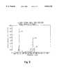
- FIG. 5illustrates a frequency spectrum showing the patrol vehicle signal, a target signal and the search window.
- FIG. 1illustrates a DSP radar unit 10 with an antenna 12 for sending and receiving radar signals.
- Radar return signals received by antenna 12are converted from analog to digital by A to D converter 14, and input to signal processing system 16 containing a digital signal processor (DSP).
- DSPdigital signal processor
- a DSP traffic radar unittransmits a single frequency microwave signal toward moving and stationary targets. A portion of the microwave signal is reflected by the targets and is received, mixed, and amplified by the receiver section of antenna 12. The signal received is a composite of all signals reflected by the moving and stationary targets. Conversion of the signal from the time domain to the frequency domain by the DSP separates the targets by frequency, which is directly proportional to the speed of the target.
- the operator interfaceincluding mode selection and data display, is included in logic control system 18.
- Logic control system 18 and signal processing system 16work in tandem to control calculation, configuration, and display of targets and patrol speed.
- Output 22 from a patrol car electronic speedometer 20is connected to the DSP of signal processing system 16.
- a display window(not shown) is provided to display the patrol vehicle speed.
- the electronic speedometer 20outputs a certain number of pulses for each mile the patrol vehicle travels.
- a common value of speedometer pulsesis 8,000 pulses per mile. Therefore, when the patrol vehicle is traveling at a speed of one mile per hour, the speedometer will output (8,000 pulses per mile * 1 mile per hour) pulses per hour.
- the number of pulses per secondis found by dividing the number of pulses per mile by the number of seconds per hour. Thus, the number of pulses that occur in one second (per mile per hour) is 8,000 pulses per hour divided by 3,600 seconds per hour, which equals 2.222 pulses per second (per mile per hour).
- the sync timeis the reciprocal of this value or 1/2.222, which equals 0.450 seconds or 450 milliseconds.
- the sync timeis the amount of time needed to accumulate pulses, which is equal to the speed of the vehicle in miles per hour.
- the synchronization numberis stored and used to steer the DSP patrol search. Since the DSP does not directly use the speedometer pulses as the patrol speed, small inaccuracies of the speedometer synchronization are not important.
- the electronic speedometer output pulsesare interfaced to the DSP in signal processing system 16 by way of a level converter and a Schmitt trigger logic circuit known in the art, to an edge sensitive interrupt pin on the DSP chip (such as Analog Device ADI2185).
- the DSPcalls an interrupt service routine that counts pulses each time a speedometer pulse is received.
- Configuration and control of a traffic radar unitis typically accomplished using buttons on the front panel of the radar unit and on the remote control unit (as illustrated for example in the U.S. Pat. No. 5,528,246). Although specific buttons on the remote control unit illustrated in the '246 patent will be used to describe the operation of the present invention, their use is for example only and not a limitation of the present invention. Other buttons or controls can be used to perform the same functions.
- the operatordepresses the "patrol blank” button on the remote control unit twice while driving the patrol vehicle at a constant speed.
- the operatorrequests to synchronize the speedometer input to the patrol vehicle radar return 28, which is transformed from the time domain to the frequency domain by the DSP of Signal Processing System 16. Synchronization is typically done upon initial installation of the radar unit in the patrol vehicle or when the radar unit is moved to another vehicle. From the main loop 30, the patrol speed is displayed from the radar return 32. The entire frequency spectrum is shown in FIG. 2 after translation from the time domain with only a patrol vehicle signal 28 present. If the vehicle speedometer does not match the radar displayed speed 34, the operator can cancel the synchronization by pressing any button other than the "lock" button on the remote control unit, the routine returns to the main loop 54 and the patrol speed is found using standard searching parameters.
- the operatordepresses the "lock” button on the remote control unit and the cancel timer starts and the system enters the sync state 36. If the patrol speed is zero 38, any previous sync number and sync valid flag will be cleared 46 and the unit will display "0" as the synchronization number 50. This gives the operator a way to clear previously stored synchronization data. The sync number and cleared sync valid flag are stored 52. The routine then returns to the main loop 54 and the patrol speed is found using standard searching parameters.
- a loopis entered where speedometer pulses are accumulated 40 until either the patrol speed equals the speedometer pulses 42 or the cancel timer has expired. If the patrol speed does not equal the speedometer pulses 42 and cancel timer has not expired 44, speedometer pulses continue to accumulate 40. If the cancel timer has expired 44, the sync number and sync valid are cleared 46 and the unit will display "0" as the synchronization number 50 and store the sync number and cleared sync valid flag 52. The routine then returns to the main loop 54 and the patrol speed is found using standard searching parameters.
- the sync numberis calculated from the elapsed cancel timer and the sync valid flag is set 48.
- the sync numberis displayed 50 and the sync number and sync valid flag are stored in non-volatile memory 52. The unit then returns to the main loop 54.
- the sync number and the sync valid flagare sent to the DSP from nonvolatile memory.
- the DSP synchronization softwareis only executed upon operator command when it is necessary to synchronize the radar unit with the speedometer, or to clear previously stored parameters.
- FIG. 5illustrates the frequency spectrum with a patrol vehicle signal 28 and target vehicle signal 96.
- the patrol vehicleis moving at a higher speed and in the same direction as the target vehicle. If the counting interval has completed 74 and there were some speedometer pulses counted during the counting interval 76, and the number of pulses are within the patrol range 78, the pulse count is converted from the time domain to the equivalent bin number in the frequency domain of the Doppler spectra 80.
- the patrol speed search window 81is set to plus or minus five MPH (or KPH) of the speedometer bin 82 and the counting interval timer is reset 84.
- the patrol vehicle returnis searched for within the search interval 86.
- the routinereturns to the main loop 94 to search for other targets 96.
- the patrol speedis zero indicating that the patrol vehicle has stopped and since the search range is set to zero, the patrol vehicle speed is set to zero and the patrol vehicle search range is set to zero 92.
- the counting interval timeis reset 84, and the patrol vehicle return is searched for within the search range 86. Since the search range is set to zero, the patrol vehicle speed is set to zero and the routine returns to the main loop 82 to search for other targets.
- the default search rangeis restored 90.
- the counting intervalis reset 84 and the routine searches for the patrol vehicle 86 using standard searching parameters. The routine then returns to the main routine 94 to search for other targets.
- the present inventionunambiguously determines the patrol vehicle speed eliminating erroneous target speed calculation and display.
Landscapes
- Engineering & Computer Science (AREA)
- Radar, Positioning & Navigation (AREA)
- Remote Sensing (AREA)
- Physics & Mathematics (AREA)
- Computer Networks & Wireless Communication (AREA)
- General Physics & Mathematics (AREA)
- Electromagnetism (AREA)
- Radar Systems Or Details Thereof (AREA)
Abstract
Description
Claims (10)
Priority Applications (1)
| Application Number | Priority Date | Filing Date | Title |
|---|---|---|---|
| US09/201,284US6023236A (en) | 1998-11-30 | 1998-11-30 | Speedometer assisted patrol speed search for DSP traffic radar |
Applications Claiming Priority (1)
| Application Number | Priority Date | Filing Date | Title |
|---|---|---|---|
| US09/201,284US6023236A (en) | 1998-11-30 | 1998-11-30 | Speedometer assisted patrol speed search for DSP traffic radar |
Publications (1)
| Publication Number | Publication Date |
|---|---|
| US6023236Atrue US6023236A (en) | 2000-02-08 |
Family
ID=22745238
Family Applications (1)
| Application Number | Title | Priority Date | Filing Date |
|---|---|---|---|
| US09/201,284Expired - LifetimeUS6023236A (en) | 1998-11-30 | 1998-11-30 | Speedometer assisted patrol speed search for DSP traffic radar |
Country Status (1)
| Country | Link |
|---|---|
| US (1) | US6023236A (en) |
Cited By (16)
| Publication number | Priority date | Publication date | Assignee | Title |
|---|---|---|---|---|
| US6400309B1 (en) | 1999-10-15 | 2002-06-04 | Mph Industries, Inc. | Doppler-based traffic radar system and related method of operation without detection |
| US6501418B1 (en)* | 2002-04-09 | 2002-12-31 | Applied Concepts, Inc. | Patrol speed acquisition in police Doppler radar |
| US6501417B1 (en) | 2001-11-13 | 2002-12-31 | Mph Industries, Inc. | Transceiver assembly used in a Doppler-based traffic radar system |
| US6580386B1 (en)* | 2001-08-16 | 2003-06-17 | Applied Concepts, Inc. | System and method for processing radar data |
| US6587068B2 (en) | 2001-10-09 | 2003-07-01 | Escort Inc. | Police radar/laser detector with integral vehicle parameter display |
| US6744379B1 (en) | 2001-08-16 | 2004-06-01 | Applied Concepts, Inc. | System and method for displaying radar data |
| US20040246171A1 (en)* | 2001-10-09 | 2004-12-09 | Escort Inc. | Police radar/laser detector with integral vehicle parameter display using a vehicle interface |
| US20050146458A1 (en)* | 2004-01-07 | 2005-07-07 | Carmichael Steve D. | Vehicular electronics interface module and related methods |
| US20050253749A1 (en)* | 2004-05-14 | 2005-11-17 | Shelton Maurice E | Traffic radar system with improved patrol speed capture |
| ES2335453A1 (en)* | 2007-05-17 | 2010-03-26 | Universidad Politecnica De Madrid | SYSTEM OF VERIFICATION OF THE QUALITY OF THE SPEED MEASURE IN SYSTEMS BASED ON RADAR DOPPLER. |
| US7705772B1 (en) | 2009-01-19 | 2010-04-27 | Kustom Signals, Inc. | Traffic radar with target duration tracking |
| CN101320086B (en)* | 2008-06-27 | 2011-03-30 | 北京航空航天大学 | Echo signal processing device and method of a Doppler speed measuring lidar |
| US10162051B2 (en) | 2014-03-13 | 2018-12-25 | Kustom Signals, Inc. | USB/Wireless based traffic radar system |
| US10488426B2 (en) | 2017-07-21 | 2019-11-26 | Applied Concepts, Inc. | System for determining speed and related mapping information for a speed detector |
| US10984253B2 (en) | 2013-06-06 | 2021-04-20 | Kustom Signals, Inc. | Traffic enforcement system with time tracking and integrated video capture |
| US11579314B2 (en) | 2017-10-09 | 2023-02-14 | Kustom Signals, Inc. | Traffic radar system with patrol vehicle speed detection |
Citations (12)
| Publication number | Priority date | Publication date | Assignee | Title |
|---|---|---|---|---|
| US4335382A (en)* | 1980-03-10 | 1982-06-15 | Decatur Electronics, Inc. | Traffic radar system |
| US5381155A (en)* | 1993-12-08 | 1995-01-10 | Gerber; Eliot S. | Vehicle speeding detection and identification |
| US5525996A (en)* | 1995-02-10 | 1996-06-11 | Applied Concepts, Inc. | Police traffic radar for calculating and simultaneously displaying fastest target speed |
| US5528246A (en)* | 1994-06-30 | 1996-06-18 | Kustom Signals, Inc. | Traffic radar with digital signal processing |
| US5528245A (en)* | 1995-02-10 | 1996-06-18 | Applied Concepts, Inc. | Police traffic radar using double balanced mixer for even order harmonic suppression |
| US5563603A (en)* | 1995-02-10 | 1996-10-08 | Aker; John L. | Police traffic radar using digital data transfer between antenna and counting unit |
| US5565871A (en)* | 1995-02-10 | 1996-10-15 | Applied Concepts Inc. | Police traffic radar for allowing manual rejection of incorrect patrol speed display |
| US5570093A (en)* | 1995-02-10 | 1996-10-29 | Applied Concepts, Inc. | Police traffic radar using absolute signal strength information to improve target signal processing accuracy |
| ES2091756T3 (en)* | 1988-07-14 | 1996-11-16 | Multanova Ag | PROCEDURE AND DEVICE FOR VEHICLE SPEED MONITORING THROUGH A RADAR-DOPPLER SPEED MEASUREMENT FACILITY AS WELL AS THE PROCEDURE APPLICATION. |
| US5815092A (en)* | 1997-04-22 | 1998-09-29 | Gregg, Iii; Eugene Stuart | Combined speed measuring device detector, speed measuring device and printer for verifying vehicle speed |
| US5912822A (en)* | 1994-06-01 | 1999-06-15 | American Traffic Systems, Inc. | Frequency domain processing of Doppler signals in a traffic monitoring system |
| US5935190A (en)* | 1994-06-01 | 1999-08-10 | American Traffic Systems, Inc. | Traffic monitoring system |
- 1998
- 1998-11-30USUS09/201,284patent/US6023236A/ennot_activeExpired - Lifetime
Patent Citations (13)
| Publication number | Priority date | Publication date | Assignee | Title |
|---|---|---|---|---|
| US4335382A (en)* | 1980-03-10 | 1982-06-15 | Decatur Electronics, Inc. | Traffic radar system |
| ES2091756T3 (en)* | 1988-07-14 | 1996-11-16 | Multanova Ag | PROCEDURE AND DEVICE FOR VEHICLE SPEED MONITORING THROUGH A RADAR-DOPPLER SPEED MEASUREMENT FACILITY AS WELL AS THE PROCEDURE APPLICATION. |
| US5381155A (en)* | 1993-12-08 | 1995-01-10 | Gerber; Eliot S. | Vehicle speeding detection and identification |
| US5935190A (en)* | 1994-06-01 | 1999-08-10 | American Traffic Systems, Inc. | Traffic monitoring system |
| US5912822A (en)* | 1994-06-01 | 1999-06-15 | American Traffic Systems, Inc. | Frequency domain processing of Doppler signals in a traffic monitoring system |
| US5528246A (en)* | 1994-06-30 | 1996-06-18 | Kustom Signals, Inc. | Traffic radar with digital signal processing |
| US5565871A (en)* | 1995-02-10 | 1996-10-15 | Applied Concepts Inc. | Police traffic radar for allowing manual rejection of incorrect patrol speed display |
| US5570093A (en)* | 1995-02-10 | 1996-10-29 | Applied Concepts, Inc. | Police traffic radar using absolute signal strength information to improve target signal processing accuracy |
| US5563603A (en)* | 1995-02-10 | 1996-10-08 | Aker; John L. | Police traffic radar using digital data transfer between antenna and counting unit |
| US5691724A (en)* | 1995-02-10 | 1997-11-25 | Aker; John L. | Police traffic radar using FFT processing to find fastest target |
| US5528245A (en)* | 1995-02-10 | 1996-06-18 | Applied Concepts, Inc. | Police traffic radar using double balanced mixer for even order harmonic suppression |
| US5525996A (en)* | 1995-02-10 | 1996-06-11 | Applied Concepts, Inc. | Police traffic radar for calculating and simultaneously displaying fastest target speed |
| US5815092A (en)* | 1997-04-22 | 1998-09-29 | Gregg, Iii; Eugene Stuart | Combined speed measuring device detector, speed measuring device and printer for verifying vehicle speed |
Non-Patent Citations (10)
| Title |
|---|
| "35-GHz-Doppler radar for law enforcement agencies in Europe", Westphal, R.; Kessler, A., Microwave Symposium Digest, 1988., IEEE MTT-S International, 1988, pp.: 1031-1033 vol. 2. |
| "Improving on police radar", Fisher, P.D., IEEE Spectrum vol.: 29 7, Jul. 1992, pp.: 38-43. |
| "Millimeter wave safety warning system for in-vehicle signing", Greneker, G., IEEE Aerospace and Electronics Systems Magazine vol.: 13 7, Jul. 1998, pp.: 7-12. |
| "Radar Speed Monitoring System", Sato, Y., Vehicle Navigation and Information Systems Conference, 1994.Proceedings., 1994, 1994, pp.: 89-93. |
| "Spread spectrum for commercial communications", Schilling, D.L.; Milstein, L.B.; Pickholtz, R.L.; Kullback, M.; Miller, F., IEEE Communications Magazine Vol.: 29 4, Apr. 1991, pp.: 66-79. |
| 35 GHz Doppler radar for law enforcement agencies in Europe , Westphal, R.; Kessler, A., Microwave Symposium Digest, 1988., IEEE MTT S International, 1988, pp.: 1031 1033 vol. 2.* |
| Improving on police radar , Fisher, P.D., IEEE Spectrum vol.: 29 7, Jul. 1992, pp.: 38 43.* |
| Millimeter wave safety warning system for in vehicle signing , Greneker, G., IEEE Aerospace and Electronics Systems Magazine vol.: 13 7, Jul. 1998, pp.: 7 12.* |
| Radar Speed Monitoring System , Sato, Y., Vehicle Navigation and Information Systems Conference, 1994.Proceedings., 1994, 1994, pp.: 89 93.* |
| Spread spectrum for commercial communications , Schilling, D.L.; Milstein, L.B.; Pickholtz, R.L.; Kullback, M.; Miller, F., IEEE Communications Magazine Vol.: 29 4, Apr. 1991, pp.: 66 79.* |
Cited By (28)
| Publication number | Priority date | Publication date | Assignee | Title |
|---|---|---|---|---|
| US20060055583A1 (en)* | 1999-06-14 | 2006-03-16 | Escort Inc. | Acceleration detector with integral vehicle parameter display using a vehicle interface |
| US7397416B2 (en) | 1999-06-14 | 2008-07-08 | Escort Inc. | Police radar/laser detector with integral vehicle parameter display using a vehicle interface |
| US20060284756A1 (en)* | 1999-06-14 | 2006-12-21 | Escort Inc. | Police Radar/Laser Detector with Integral Vehicle Parameter Display Using a Vehicle Interface |
| US7098844B2 (en) | 1999-06-14 | 2006-08-29 | Escort Inc. | Acceleration detector with integral vehicle parameter display using a vehicle interface |
| US6400309B1 (en) | 1999-10-15 | 2002-06-04 | Mph Industries, Inc. | Doppler-based traffic radar system and related method of operation without detection |
| US7411544B2 (en)* | 2001-08-16 | 2008-08-12 | Applied Concepts, Inc. | System and method for determining patrol speed |
| US6580386B1 (en)* | 2001-08-16 | 2003-06-17 | Applied Concepts, Inc. | System and method for processing radar data |
| US6744379B1 (en) | 2001-08-16 | 2004-06-01 | Applied Concepts, Inc. | System and method for displaying radar data |
| US20040222921A1 (en)* | 2001-08-16 | 2004-11-11 | Aker John L. | System and method for determining patrol speed |
| US6831593B2 (en)* | 2001-08-16 | 2004-12-14 | Applied Concepts, Inc. | System and method for processing radar data |
| US20040246171A1 (en)* | 2001-10-09 | 2004-12-09 | Escort Inc. | Police radar/laser detector with integral vehicle parameter display using a vehicle interface |
| US6836238B1 (en) | 2001-10-09 | 2004-12-28 | Escort Inc. | Police radar/laser detector with integral vehicle parameter display using a vehicle interface |
| US6587068B2 (en) | 2001-10-09 | 2003-07-01 | Escort Inc. | Police radar/laser detector with integral vehicle parameter display |
| US6501417B1 (en) | 2001-11-13 | 2002-12-31 | Mph Industries, Inc. | Transceiver assembly used in a Doppler-based traffic radar system |
| US6501418B1 (en)* | 2002-04-09 | 2002-12-31 | Applied Concepts, Inc. | Patrol speed acquisition in police Doppler radar |
| US20050146458A1 (en)* | 2004-01-07 | 2005-07-07 | Carmichael Steve D. | Vehicular electronics interface module and related methods |
| US7091901B2 (en)* | 2004-05-14 | 2006-08-15 | Kustom Signals, Inc. | Traffic radar system with improved patrol speed capture |
| US20050253749A1 (en)* | 2004-05-14 | 2005-11-17 | Shelton Maurice E | Traffic radar system with improved patrol speed capture |
| ES2335453A1 (en)* | 2007-05-17 | 2010-03-26 | Universidad Politecnica De Madrid | SYSTEM OF VERIFICATION OF THE QUALITY OF THE SPEED MEASURE IN SYSTEMS BASED ON RADAR DOPPLER. |
| CN101320086B (en)* | 2008-06-27 | 2011-03-30 | 北京航空航天大学 | Echo signal processing device and method of a Doppler speed measuring lidar |
| US7705772B1 (en) | 2009-01-19 | 2010-04-27 | Kustom Signals, Inc. | Traffic radar with target duration tracking |
| US10984253B2 (en) | 2013-06-06 | 2021-04-20 | Kustom Signals, Inc. | Traffic enforcement system with time tracking and integrated video capture |
| US10162051B2 (en) | 2014-03-13 | 2018-12-25 | Kustom Signals, Inc. | USB/Wireless based traffic radar system |
| US10488426B2 (en) | 2017-07-21 | 2019-11-26 | Applied Concepts, Inc. | System for determining speed and related mapping information for a speed detector |
| US11579314B2 (en) | 2017-10-09 | 2023-02-14 | Kustom Signals, Inc. | Traffic radar system with patrol vehicle speed detection |
| US11703602B2 (en) | 2017-10-09 | 2023-07-18 | Kustom Signals, Inc. | Traffic radar system with patrol vehicle speed detection |
| US11977172B2 (en) | 2017-10-09 | 2024-05-07 | Kustom Signals, Inc. | Traffic radar system with patrol vehicle speed detection |
| US11982754B2 (en) | 2017-10-09 | 2024-05-14 | Kustom Signals, Inc. | Traffic radar system with patrol vehicle speed detection |
Similar Documents
| Publication | Publication Date | Title |
|---|---|---|
| US6023236A (en) | Speedometer assisted patrol speed search for DSP traffic radar | |
| EP0655141B1 (en) | Multi-frequency, multi-target vehicular radar system using digital signal processing | |
| US5977884A (en) | Radar detector responsive to vehicle speed | |
| EP1371997B1 (en) | Method for detecting stationary object on road by radar | |
| US5528246A (en) | Traffic radar with digital signal processing | |
| US4348675A (en) | FM-CW Radar system for use in an automotive vehicle | |
| US20040027273A1 (en) | Method for adaptive target processing in a motor vehicle radar system | |
| JP3401618B2 (en) | Radar apparatus and noise level threshold changing method | |
| GB2283631A (en) | Radar | |
| US4180816A (en) | Testing circuit for radar-operated vehicle safety assurance systems | |
| US20050116855A1 (en) | Device and method for registering, detecting, and/or analyzing at least one object | |
| JP3346867B2 (en) | Stationary object identification type mobile radar device | |
| US6501418B1 (en) | Patrol speed acquisition in police Doppler radar | |
| US5940024A (en) | Onboard radar system for a vehicle | |
| US5861836A (en) | Circuit configuration having radar equipment for determining a distance or a relative speed | |
| US20090135050A1 (en) | Automotive radar system | |
| US5760743A (en) | Miss distance indicator data processing and recording apparatus | |
| JPH0883400A (en) | Vehicle obstacle identification system | |
| JPH09133765A (en) | FM-CW radar device | |
| US7091901B2 (en) | Traffic radar system with improved patrol speed capture | |
| JP3114700B2 (en) | FM-CW radar device | |
| JP2656051B2 (en) | Navigation device for mobile objects | |
| JPH1090390A (en) | Navigation device for vehicle | |
| JPH0545449A (en) | Radar apparatus and target tracking method | |
| JPH0146836B2 (en) |
Legal Events
| Date | Code | Title | Description |
|---|---|---|---|
| AS | Assignment | Owner name:KUSTOM SIGNALS, INC., KANSAS Free format text:ASSIGNMENT OF ASSIGNORS INTEREST;ASSIGNOR:SHELTON, MAURICE E.;REEL/FRAME:009617/0214 Effective date:19981103 | |
| STCF | Information on status: patent grant | Free format text:PATENTED CASE | |
| AS | Assignment | Owner name:LEHMAN COMMERCIAL PAPER INC., NEW YORK Free format text:SECURITY AGREEMENT;ASSIGNOR:KUSTOM SIGNALS, INC.;REEL/FRAME:012110/0166 Effective date:20010814 | |
| FPAY | Fee payment | Year of fee payment:4 | |
| AS | Assignment | Owner name:KUSTOM SIGNALS, INC., MISSOURI Free format text:RELEASE BY SECURED PARTY;ASSIGNOR:LEHMAN COMMERCIAL PAPER, INC.;REEL/FRAME:016862/0176 Effective date:20051031 | |
| AS | Assignment | Owner name:THE GOVERNOR AND COMPANY OF THE BANK OF SCOTLAND, Free format text:SECURITY AGREEMENT;ASSIGNOR:KUSTOM SIGNALS, INC.;REEL/FRAME:016987/0644 Effective date:20051222 | |
| AS | Assignment | Owner name:BARCLAYS BANK PLC, UNITED KINGDOM Free format text:SECURITY AGREEMENT;ASSIGNOR:KUSTOM SIGNALS, INC.;REEL/FRAME:019134/0523 Effective date:20070403 | |
| REMI | Maintenance fee reminder mailed | ||
| FPAY | Fee payment | Year of fee payment:8 | |
| SULP | Surcharge for late payment | Year of fee payment:7 | |
| AS | Assignment | Owner name:KUSTOM SIGNALS, INC., KANSAS Free format text:RELEASE BY SECURED PARTY;ASSIGNOR:THE GOVERNOR AND COMPANY OF THE BANK OF SCOTLAND;REEL/FRAME:024697/0518 Effective date:20070403 | |
| FPAY | Fee payment | Year of fee payment:12 | |
| AS | Assignment | Owner name:BARCLAYS BANK PLC, UNITED KINGDOM Free format text:SECURITY AGREEMENT;ASSIGNOR:KUSTOM SIGNALS, INC.;REEL/FRAME:031747/0497 Effective date:20100521 | |
| AS | Assignment | Owner name:KUSTOM SIGNALS, INC., KANSAS Free format text:RELEASE BY SECURED PARTY;ASSIGNOR:BARCLAYS BANK PLC;REEL/FRAME:032618/0516 Effective date:20140327 Owner name:KUSTOM SIGNALS, INC., KANSAS Free format text:RELEASE BY SECURED PARTY;ASSIGNOR:BARCLAYS BANK PLC;REEL/FRAME:032618/0727 Effective date:20140327 | |
| AS | Assignment | Owner name:PNC BANK, NATIONAL ASSOCIATION, PENNSYLVANIA Free format text:SECURITY INTEREST;ASSIGNOR:KUSTOM SIGNALS, INC.;REEL/FRAME:046656/0448 Effective date:20180725 |