US6023166A - MRI antenna - Google Patents
MRI antennaDownload PDFInfo
- Publication number
- US6023166A US6023166AUS08/974,080US97408097AUS6023166AUS 6023166 AUS6023166 AUS 6023166AUS 97408097 AUS97408097 AUS 97408097AUS 6023166 AUS6023166 AUS 6023166A
- Authority
- US
- United States
- Prior art keywords
- primary
- radio frequency
- antenna
- primary coil
- plane
- Prior art date
- Legal status (The legal status is an assumption and is not a legal conclusion. Google has not performed a legal analysis and makes no representation as to the accuracy of the status listed.)
- Expired - Lifetime
Links
- 238000004804windingMethods0.000claimsabstractdescription73
- 238000002595magnetic resonance imagingMethods0.000claimsabstractdescription57
- 210000000481breastAnatomy0.000claimsabstractdescription53
- 239000003990capacitorSubstances0.000claimsdescription45
- 230000008878couplingEffects0.000claimsdescription8
- 238000010168coupling processMethods0.000claimsdescription8
- 238000005859coupling reactionMethods0.000claimsdescription8
- 206010051131MastoptosisDiseases0.000claimsdescription3
- 230000001939inductive effectEffects0.000claimsdescription3
- 238000000034methodMethods0.000abstractdescription13
- 238000012545processingMethods0.000abstractdescription2
- 230000035945sensitivityEffects0.000description15
- 238000003384imaging methodMethods0.000description11
- 210000000779thoracic wallAnatomy0.000description7
- 210000000038chestAnatomy0.000description6
- 229910052739hydrogenInorganic materials0.000description6
- 239000001257hydrogenSubstances0.000description6
- RYGMFSIKBFXOCR-UHFFFAOYSA-NCopperChemical compound[Cu]RYGMFSIKBFXOCR-UHFFFAOYSA-N0.000description5
- UFHFLCQGNIYNRP-UHFFFAOYSA-NHydrogenChemical compound[H][H]UFHFLCQGNIYNRP-UHFFFAOYSA-N0.000description5
- 229910052802copperInorganic materials0.000description5
- 239000010949copperSubstances0.000description5
- 239000006260foamSubstances0.000description5
- 206010028980NeoplasmDiseases0.000description3
- 230000001419dependent effectEffects0.000description3
- 239000010410layerSubstances0.000description3
- 239000000463materialSubstances0.000description3
- 210000002445nippleAnatomy0.000description3
- 239000004033plasticSubstances0.000description3
- 229920003023plasticPolymers0.000description3
- 238000005481NMR spectroscopyMethods0.000description2
- 229920006362Teflon®Polymers0.000description2
- 230000005856abnormalityEffects0.000description2
- 239000011248coating agentSubstances0.000description2
- 238000000576coating methodMethods0.000description2
- 239000004020conductorSubstances0.000description2
- 230000007423decreaseEffects0.000description2
- 229920001971elastomerPolymers0.000description2
- 230000003068static effectEffects0.000description2
- 239000013598vectorSubstances0.000description2
- IJGRMHOSHXDMSA-UHFFFAOYSA-NAtomic nitrogenChemical compoundN#NIJGRMHOSHXDMSA-UHFFFAOYSA-N0.000description1
- 206010006187Breast cancerDiseases0.000description1
- 208000026310Breast neoplasmDiseases0.000description1
- OKTJSMMVPCPJKN-UHFFFAOYSA-NCarbonChemical compound[C]OKTJSMMVPCPJKN-UHFFFAOYSA-N0.000description1
- OKTJSMMVPCPJKN-OUBTZVSYSA-NCarbon-13Chemical compound[13C]OKTJSMMVPCPJKN-OUBTZVSYSA-N0.000description1
- 210000003484anatomyAnatomy0.000description1
- 230000005540biological transmissionEffects0.000description1
- 229910052799carbonInorganic materials0.000description1
- 238000001514detection methodMethods0.000description1
- 238000003745diagnosisMethods0.000description1
- 230000003292diminished effectEffects0.000description1
- 238000007598dipping methodMethods0.000description1
- 230000005284excitationEffects0.000description1
- BHEPBYXIRTUNPN-UHFFFAOYSA-Nhydridophosphorus(.) (triplet)Chemical compound[PH]BHEPBYXIRTUNPN-UHFFFAOYSA-N0.000description1
- 150000002431hydrogenChemical class0.000description1
- 239000007943implantSubstances0.000description1
- 238000003780insertionMethods0.000description1
- 230000037431insertionEffects0.000description1
- 230000001678irradiating effectEffects0.000description1
- 238000012986modificationMethods0.000description1
- 230000004048modificationEffects0.000description1
- 229920001296polysiloxanePolymers0.000description1
- 239000011241protective layerSubstances0.000description1
- KEAYESYHFKHZAL-IGMARMGPSA-Nsodium-23 atomChemical compound[23Na]KEAYESYHFKHZAL-IGMARMGPSA-N0.000description1
- 239000007779soft materialSubstances0.000description1
- 239000007787solidSubstances0.000description1
- 239000007921spraySubstances0.000description1
- 238000012546transferMethods0.000description1
- 125000000391vinyl groupChemical group[H]C([*])=C([H])[H]0.000description1
- 229920002554vinyl polymerPolymers0.000description1
Images


Classifications
- G—PHYSICS
- G01—MEASURING; TESTING
- G01R—MEASURING ELECTRIC VARIABLES; MEASURING MAGNETIC VARIABLES
- G01R33/00—Arrangements or instruments for measuring magnetic variables
- G01R33/20—Arrangements or instruments for measuring magnetic variables involving magnetic resonance
- G01R33/28—Details of apparatus provided for in groups G01R33/44 - G01R33/64
- G01R33/32—Excitation or detection systems, e.g. using radio frequency signals
- G01R33/36—Electrical details, e.g. matching or coupling of the coil to the receiver
- G01R33/3628—Tuning/matching of the transmit/receive coil
- G—PHYSICS
- G01—MEASURING; TESTING
- G01R—MEASURING ELECTRIC VARIABLES; MEASURING MAGNETIC VARIABLES
- G01R33/00—Arrangements or instruments for measuring magnetic variables
- G01R33/20—Arrangements or instruments for measuring magnetic variables involving magnetic resonance
- G01R33/28—Details of apparatus provided for in groups G01R33/44 - G01R33/64
- G01R33/32—Excitation or detection systems, e.g. using radio frequency signals
- G01R33/34—Constructional details, e.g. resonators, specially adapted to MR
- G01R33/34046—Volume type coils, e.g. bird-cage coils; Quadrature bird-cage coils; Circularly polarised coils
- G01R33/34053—Solenoid coils; Toroidal coils
- G—PHYSICS
- G01—MEASURING; TESTING
- G01R—MEASURING ELECTRIC VARIABLES; MEASURING MAGNETIC VARIABLES
- G01R33/00—Arrangements or instruments for measuring magnetic variables
- G01R33/20—Arrangements or instruments for measuring magnetic variables involving magnetic resonance
- G01R33/28—Details of apparatus provided for in groups G01R33/44 - G01R33/64
- G01R33/32—Excitation or detection systems, e.g. using radio frequency signals
- G01R33/34—Constructional details, e.g. resonators, specially adapted to MR
- G01R33/34084—Constructional details, e.g. resonators, specially adapted to MR implantable coils or coils being geometrically adaptable to the sample, e.g. flexible coils or coils comprising mutually movable parts
- G—PHYSICS
- G01—MEASURING; TESTING
- G01R—MEASURING ELECTRIC VARIABLES; MEASURING MAGNETIC VARIABLES
- G01R33/00—Arrangements or instruments for measuring magnetic variables
- G01R33/20—Arrangements or instruments for measuring magnetic variables involving magnetic resonance
- G01R33/28—Details of apparatus provided for in groups G01R33/44 - G01R33/64
- G01R33/32—Excitation or detection systems, e.g. using radio frequency signals
- G01R33/34—Constructional details, e.g. resonators, specially adapted to MR
- G01R33/341—Constructional details, e.g. resonators, specially adapted to MR comprising surface coils
- G01R33/3415—Constructional details, e.g. resonators, specially adapted to MR comprising surface coils comprising arrays of sub-coils, i.e. phased-array coils with flexible receiver channels
Definitions
- This inventionrelates to radio frequency antennas for use in magnetic resonance imaging. More particularly, this invention relates to radio frequency antennas for use in the magnetic resonance imaging of a woman's breasts.
- the antennacan be used to receive magnetic resonance imaging signals from the woman's breast and surrounding area, as well as to transmit radio frequency pulses to the patient.
- Magnetic resonance imagingis a well known, highly useful technique for diagnosing abnormalities in biological tissue. MRI can detect abnormalities which are difficult or impossible to detect by other techniques, without the use of x-rays or invasive procedures.
- Magnetic resonance imaginguses changes in the angular momentum or spin of the atomic nuclei of certain elements within body tissue in a static magnetic field after excitation by radio frequency energy, to derive images containing useful information concerning the condition of the tissue.
- the patientis inserted into an imaging volume containing a static magnetic field.
- the vector of the angular momentum or spin of nuclei containing an odd number of protons or neutronstends to align with the direction of the magnetic field.
- Irradiating the tissue within the imaging volume by a pulse or pulses of radio frequency energy having a particular bandwidth of frequency, referred to as the resonant or Larmor frequencyshifts the vectors of those nuclei out of alignment with the applied magnetic field.
- the spins of the nucleithen turn or "precess" around the direction of the applied primary magnetic field.
- the nucleiemit small radio frequency signals, referred to as magnetic resonance ("MR") signals, at the resonant or Larmor frequency, which are detected by a radio frequency antenna tuned to that frequency.
- Gradient magnetic fieldsare provided to spatially encode the MR signals emitted by the nuclei.
- the precessing spinsgradually drift out of phase with one another, back into alignment with the direction of the applied magnetic field. This causes the MR signals emitted by the nuclei to decay.
- the MR signalsare detected by a radio frequency receiving antenna positioned within the imaging volume proximate the patient, and are amplified, digitized and processed by the MRI system. Hydrogen, nitrogen-14, phosphorous 31, carbon 13 and sodium 23 are typical nuclei detected by MRI. Hydrogen is most commonly detected because it is the most abundant nuclei in the human body and emits the strongest MR signal.
- the rate of decay of the MR signalsvaries for different types of tissue, including injured or diseased tissue, such as cancerous tissue.
- tissueincluding injured or diseased tissue, such as cancerous tissue.
- mathematical techniquesinvolving correlation of the gradient magnetic field and the particular frequency of the radio frequency waves applied at various times with the rate of decay of the MR signals emitted by the patient, it is possible to determine the concentrations and the condition of the environment of the nuclei of interest at various locations within the patient's body. This information is typically displayed as an image with varying intensities, which are a function of the concentration and environment of the nuclei of interest.
- Typical MRI systemsare the Quad 7000 and Quad 12000 available from FONAR Corporation, Melville, N.Y., for example.
- the quality of the magnetic resonance imageis directly related to the characteristics of the receiving antenna.
- Significant electrical characteristics of the antennainclude sensitivity, Q factor and the signal-to-noise ratio.
- Sensitivityis the signal voltage generated in the receiving antenna by MR signals of a particular magnitude. The higher the sensitivity within the region to be imaged, the weaker the signals which can be detected.
- the sensitivity of the antennais preferably substantially uniform with respect to MR signals emanating from all volume elements within the region of the subject which is to be imaged.
- the Q or quality factorwhich is closely related to sensitivity of the antenna, is a measure of the ability of the antenna to amplify the received signal.
- the Q-value of the antennacan be lowered by a patient proximate or within an antenna, due to inductive coupling between the patient and the antenna. Antennas must therefore have a high Q-value when they are unloaded and the Q-value must not become too diminished by the presence of the patient.
- the coilmust couple well with the region of a patient's anatomy which is to be imaged.
- Signal-to-noise ratiois the ratio between those components in the electrical impulses appearing at the antenna terminals representing the detected MR signals, to the components representing spurious electromagnetic signals in the environment, and internally generated thermal noise from the patient.
- the antennashould have low sensitivity to signals from outside the region to be imaged.
- the antennais "tuned" or arranged to resonate electrically at the frequency of the MR signals to be received, typically several megahertz or more. Neither the coil size nor geometry of the antenna can therefore create an inductance or self-capacitance which prevents tuning to the desired frequency.
- the antennamust also meet certain physical requirements.
- the antennashould have a high filling factor, which maximizes the amount of tissue which fits within the volume detected by the windings of the coil.
- the antennamust also fit within the relatively small imaging volumes typically provided for receiving the subject within the magnet assembly, along with other components of the system and the subject. The antenna should not cause significant discomfort to the subject. Additionally, the antenna should be easy to position with respect to the subject, and be relatively insensitive to minor faults in positioning relative to the subject.
- the sensitivity and signal-to-noise ratio of radio frequency antennas for use in MRIhave been improved by providing a secondary coil, tuned to resonate at the Larmor frequency of the element of interest, for being positioned proximate the part of the subject which is to be imaged, and a similarly tuned primary coil, typically a single loop, for being positioned adjacent the secondary winding.
- the primary and secondary coilsare inductively coupled to each other.
- the primary windingis connected to the pre-amplifier of the MRI system.
- MR signals emitted by the patientinduce voltages in the secondary winding, causing current to flow within the winding.
- the currentgenerates a magnetic field which induces voltage in the primary winding.
- the MR signalsmay be received by the primary coil, as well.
- the secondary and primary coilsamplify the MR signals, and the primary coil filters spurious signals outside of the frequency band of the Larmor frequency. See, for example, U.S. Pat. No. 5,583,438 and U.S. Pat. No. 5,575,287, assigned to the assignee of the present invention.
- MRIenables very accurate discrimination between healthy and cancerous tissue without the discomfort of more traditional techniques.
- MRIcan be used to detect leakage of silicone from breast implants. While expensive, recent innovations can make MRI examination of the breast region of a patient economical.
- U.S. Pat. No. 5,490,513for example, assigned to the assignee of the present invention, teaches a method and apparatus for increasing patient throughput, and hence the efficiency of the use of the MRI system, by providing multiple patient handling systems in an MRI system with multiple entrances to the imaging volume.
- a second patientis being positioned and prepared for imaging on the second patient handling system.
- the imaging procedureis completed on the first patient
- the second patientis inserted into the imaging volume through a second entrance and imaged, while a third patient is being prepared on the first or another patient handling system.
- a greater number of patientscan thereby be imaged in a limited period of time.
- Tumorscan be located both in the breast tissue and in the chest wall surrounding and underlying the breast.
- the ability to detect tumors in the chest wall in addition to the breast tissuedepends in part on the ability of the radio frequency antenna used in the imaging process to accurately detect MR signals from the chest wall. It has also been found that MRI of the breasts is best performed with the patient in a prone position and the breasts hanging without restraint. The antenna therefore needs to be close enough to the breast tissue to adequately couple to the tissue, without compressing the breast tissue.
- a radio frequency antennawhich uniformly detects MR signals from the breast tissue and chest wall, with low signal-to-noise ratio, without compressing the breasts would be advantageous.
- an antenna for use in the magnetic resonance imaging of the breast region of a patienthaving two tuned secondary coils inductively coupled to a primary coil.
- the secondary coilswhich each define a region for receiving one of the breasts of the patient, receives magnetic resonance signals from the breast and surrounding region, including the chest wall. Voltage signals dependent upon the magnetic resonance signals detected by the secondary coils are induced in the primary coil.
- the primary coilprovides the signals to a magnetic resonance imaging system for processing.
- the primary coilmay detect magnetic resonance signals from adjacent tissue, as well.
- the coilsare tuned to the resonant or Larmor frequency of an element of interest, such as hydrogen.
- Portions of the secondary coilslie in two different intersecting planes.
- the portion in one planeis adjacent and proximate to the primary coil to achieve good inductive coupling with the primary coil. Critical coupling is preferred.
- the portion in the other planeis distanced from the primary coil, and essentially extends the range of the antenna.
- the secondary coilsinclude two windings.
- One windingis adjacent the primary coil.
- the other windinghas one portion adjacent to or proximate the primary coil, and another portion distanced from the primary coil.
- the primary coil and the adjacent or proximate portions of the secondary coilspreferably lie in a first plane while the portion of the secondary coil distanced from the primary coil lies in a second plane intersecting the first plane.
- the plane of the primary coil and adjacent portions of the secondary coilsmay be spherical.
- a cushion arrangement for conducting magnetic resonance imaging of the pendulous breasts of a prone patientincluding a base cushion having a cavity with opposed inclined side walls for supporting a portion of an antenna in a plurality of positions.
- a head cushion with a recess for supporting a top portion of the antennais provided forward of the cavity.
- a body cushionis provided rearward of the cavity.
- An additional cushionmay be provided within the cavity to further support the antenna.
- a method of collecting magnetic resonance signals from the breast region of a patientwherein the breasts of a patient are received within first and second coils of an antenna.
- the breast region of the patientis irradiated to excite the emission of magnetic resonance signals, which are simultaneously received by the first and second coils.
- the first and second coilsinduce signals in a third coil inductively coupled to the first and second coils.
- the induced signalsare transmitted from the third coil to the receiving circuitry of an MRI system.
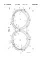
- FIG. 1is a top view of a schematic representation of a radio frequency antenna 10 in accordance with the present invention, for use in magnetic resonance imaging of the breast region of a patient;
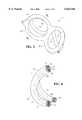
- FIG. 2is a side perspective view of the right side of the antenna 10 of FIG. 1, identifying a first plane P1 and a second plane P2;
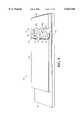
- FIG. 3is a top view of an antenna 10 in accordance with the present invention, showing the positioning of the antenna windings;
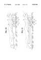
- FIG. 4is a view of the antenna of FIG. 3 along line 4--4;
- FIG. 4Ais a view of the antenna of FIG. 3, along line 4A--4A;
- FIG. 5is a rear, upper perspective view of the radio frequency antenna 10 in accordance with the present invention, covered with an insulative coating;
- FIG. 6is a cross-sectional view of antenna 10, through line 6--6 in FIG. 5;
- FIG. 7is an electrical schematic of the antenna in accordance with the present invention.
- FIG. 8is a schematic representation of the connection between the antenna of the present invention to an MRI system
- FIG. 9is a rear perspective view of a cushion arrangement for supporting the patient in a prone position on a patient bed, for use with the antenna of the present invention.
- FIGS. 10 and 11are side views of the cushions of FIG. 9, supported on a bed, with a portion removed to show the preferred placement of the antenna with respect to a large breasted woman and small breasted woman, respectively;
- FIG. 12is a rear perspective view of an alternative cushion arrangement.
- FIG. 12Ais a side view of an optional cushion for providing additional support for the antenna of the present invention.
- FIG. 1is a top view of a schematic representation of a radio frequency antenna 10 for use in magnetic resonance imaging ("MRI") of the breast region of a patient in accordance with the present invention.
- the antenna 10has a tuned primary circuit or coil 12 inductively coupled to two tuned secondary circuits or coils 14, 16.
- the primary coil 12is elongated along an axis of elongation A--A to accommodate the secondary coils 14, 16.
- the secondary coils 14, 16are adjacent to each other along the axis A--A.
- the primary coil 12has two elliptical shaped sections 12a, 12b.
- the major axes of each of the elliptical sectionslies generally in the direction of the axis A--A.
- One secondary coil 14lies within the right elliptical shaped section 12a of the primary coil 12 and the other secondary coil 16 lies within the left elliptical shaped section 12b.
- the primary coil 12includes at least one primary inductor and at least one primary capacitor connected in series to form a loop.
- the primary coil 12is preferably formed of two primary coil segments 12', 12", which are inductors, connected in series by two capacitors C 1 , C 6 . Multiple coil segments are preferred to lower the inductance of the resulting coil. Otherwise, it may be difficult to tune the coil 12 to resonate at the Larmor frequency of the element of interest in MRI systems at higher magnetic field strengths. In addition, it is believed that the decrease in direct current flow due to the presence of two or more capacitors in the circuit decreases the sensitivity of the antenna 10 to eddy currents generated by the gradient magnetic field of the MRI system.
- the secondary circuits or coils 14, 16are each spiral coils forming closed loops.
- the secondary coils 14, 16each have two windings.
- the secondary coils 14, 16include at least one secondary inductor and at least one secondary capacitor connected in series.
- the secondary coils 14, 16are also preferably formed of two secondary coil segments 18, 20 and 22, 24, having inductances and connected in series by capacitors C 2 , C 3 and C 4 , C 5 , respectively. It is preferred that the secondary coils 14, 16 be formed of multiple coil segments connected by capacitors, for the reasons described above with respect to the primary coil 12.
- the coil segments 18, 20form first windings 18, 20, and the coil segments 22, 24 form second windings 22, 24.
- the first windings 18 and 20are shaded in FIG. 1 to ease identification.
- Each of the secondary coils 14,16has portions in two different planes. One portion is adjacent and parallel to the primary coil 12 to inductively couple the secondary coils 14,16 to the primary coil 12. Another portion is distanced from the primary coil 12, to increase the filling factor of the antenna 10.
- portions 18c, 20c of the first windings 18, 20, which extends between point x and point y on the first windings 18, 20,are distanced from the primary coil 12.
- the remaining portions 18a, 18b and 20a, 20b of the first windings, and significant portions of the second windings 20, 24lie in a different plane than the portions 18c, 20c and are adjacent and parallel to, or at least proximate to, the primary coil 12.
- the adjacent, proximate and parallel spacing of the coilsis best shown in FIG. 3.
- FIG. 2is a side perspective view of the right side 12a of the primary coil 12 and the secondary coil 14, of the schematic representation of the antenna 10 of FIG. 1, superimposed on a first plane P1 and a second plane P2 which intersects the first plane P1 at an angle ⁇ , to illustrate the planar relationship between the coils in this embodiment of the invention.
- the second winding 22lies substantially in the first plane P1.
- the portion 18c of the first windinglies substantially in the second plane P2.
- Portions 18a and 18b of the first winding 18lie substantially within the first plane P1.
- the first winding 18is folded along a chord C which lies along an axis D and extends between points x-y on the first winding 18.
- the axis Dlies generally in the direction of the axis of elongation A of the primary coil, shown in FIG. 1.
- the primary coil 12preferably lies substantially in the first plane P1, as well.
- An angle ⁇ of about 30° between the first plane P1 and the second plane P2is preferred.
- the capacitor C 1 of the primary coil 12is omitted in this view.
- the secondary coil 16is a mirror image of coil 14. Therefore, portions 20a, 20b of the first winding 20, and the second winding 24 lie substantially in a first plane while portion 20c, which extends between points x and y, lies substantially in second plane.
- the two secondary circuits 14, 16are mirror images of each other, magnetic resonance ("MR") signals picked up by the secondary coils 14, 16 induce voltages which cause current to flow in opposite directions in each coil 14, 16.
- the current flowing in adjacent portions of the two secondary coils 14, 16,therefore, flow in the same direction, as indicated by the arrows 25 in FIG. 1.
- the interference between the secondary circuits 14, 16is thereby minimized, obviating the need for shielding between the circuits, even though the secondary coils 14, 16 are slightly inductively coupled, and enabling the detection of MR signals from both breasts simultaneously.
- the direction of the current in FIG. 1is exemplary.
- the currentcan flow in either direction dependent on the direction of the first windings 18, 20 and second windings 22, 24 and the direction of the applied magnetic field.
- FIG. 3is a top view of the positioning of the coils in an antenna 10 in accordance with a preferred embodiment of the present invention.
- FIG. 4is a view of the antenna 10 along line 4--4 in FIG. 3.
- FIG. 4Ais a view of the antenna 10 along line 4A--AA of FIG. 3.
- the primary coil segments 12', 12" and the secondary coil segments 18, 20 and 22, 24are contained within insulative tubing.
- the number of the tubingcorresponds to the number of the winding contained within the tubing, as identified in FIG. 1.
- the coil segmentscan be solid wires or hollow tubes of a suitable conducting material, such as copper. Teflon® is a preferred insulative tubing material. Copper is a preferred conducting material.
- the capacitors C 2 , C 3 , C 4 and C 5 connecting the wire segments of the secondary coils 14, 16,are shown in FIG. 3.
- the wire segments 12', 12" of the primary coil 12are connected to two BNC coaxial connectors 40.
- the capacitors C 1 and C 6which are not shown in this view, are connected to the BNC connectors 40.
- the primary coil 12is preferably approximately critically coupled to each of the secondary coils 14, 16. Overcoupling has been found to produce multiple resonances. To achieve the preferred degree of coupling between the primary coil 12 and the secondary coils 14, 16, the primary coil 12 is immediately adjacent to or proximate the first or second windings of each of the secondary coils 14, 16, along a substantial portion of its length. The portions of the secondary coils adjacent and proximate to the primary coil 12 substantially follow the elliptical shape of the primary coil 12, such that the adjacent and proximate portions of the primary coils 12 and secondary coils 14, 16 are parallel to each other.
- FIG. 3shows portions of the second windings 22, 24 adjacent to the primary coil segment 12". Portions of the second winding 22, 24 are also adjacent to portions of the primary coil segment 12'. Portions 18a, 20a of the second winding are adjacent to the second windings 22, 24, respectively, and proximate the primary coil segment 12'. Portions 18b, 20b of the second windings 18, 20, respectively, are also adjacent to other portions of the primary coil 12'. In those areas, portions of the second windings 22, 24 are adjacent to portions 18b, 20b, and proximate the primary coil segment 12'. In the view of FIG. 3, the second portions 18c, 22c of the first windings 18, 22 of each of the secondary coils 14,16 in the second plane extend out of the page.
- the coil segmentsare preferably hollow copper tubing with an outer diameter of about 0.125 inches. Adjacent coil segments are preferably about 0.125 inches apart to achieve the preferred critical coupling.
- FIG. 6includes a cross-sectional view of the insulative tubing 70 and copper tubing 72.
- FIG. 4is a view of the antenna 10 taken along line 4--4 in FIG. 3.
- the second portions 18c, 20c of the first windings 18, 20are shown, distanced from the primary wire segment 12".
- the primary coil 12is preferably curved to follow the contour of the chest.
- the first plane P1 containing the primary coil 12is, therefore, preferably a curved plane. Curving the primary coil 12 improves the reception of MR signals from the breast region, particularly in the chest and the outer sides of the breasts.
- the curvature of the primary coil 12is preferably about 11.5 R.
- the length "L" of the antennais about 16 inches.
- the vertical height "H2" of the primary coil 12" as measured from the bottom edge of the antenna 10 in this viewis about 3 inches.
- the vertical height "H3" of the second portions 18c, 20c of the winding 18, 20 as measured from the bottom edge of the antenna 10is about 4.5 inches.
- the secondary coils 14, 16preferably substantially follow the curvature of the primary coil 12, such that the second windings 22 and the portions 18a, 18b and 20a, 20b of the first windings, respectively, lie substantially within the same curved first plane as the primary coil 12.
- the bottom portions of the second windings 22, 24 shown in FIG. 3,are therefore obscured in the view of FIG. 4 by the primary wire segment 12".
- the windings 22 and 18a of the secondary coil 14 and windings 24 and 20a of the secondary coil 16substantially obscure the portions of the second windings 22, 24 behind them, respectively, in this view.
- the capacitors C 3 , C 4are shown covered by a protective layer of foam 42, wrapped around the capacitors and secured by ties 44.
- the foam, or other such soft material,should not contain carbon. The foam protects the capacitors during handling.
- FIG. 4Ais a side view of the antenna of FIG. 4 taken along line 4A--4A of FIG. 3.
- the primary coil 12has a curvature transverse to the axis of elongation A, which is a consequence of curving the antenna 10 to provide the curvature shown in FIG. 4.
- the curvatureis about 11.5 R. Since the curvature of the primary coil along the axis of elongation is also about 11.5 R, the primary coil 12 and the adjacent and proximate parts of the coils 14, 16 lie substantially on a spherical plane. As in FIG. 4, interior windings are obscured by the primary coil 12 in this view.
- the BNC connector 40is not shown in this view.
- the primary coil 12 and the adjacent portions of the secondary coils 14, 16lie in the same plane. However, as long as sufficient portions of the primary and secondary coils are adjacent and/or sufficiently proximate to each other to achieve the desired degree of coupling, the primary coil 12 and portions of the secondary coils 14, 16 need not be in the same plane. In either case, portions 18c, 20c of the secondary coils are distanced from the primary coil 12, to increase the filling factor of the antenna 10.
- the tubingis covered by layers of foam about 0.25 inches thick,
- the antenna 10is then covered with an electrically insulative, soft coating, such as rubber, plastic, or vinyl.
- the materialshould have a high dielectric strength to minimize capacitative losses by the antenna 10. A dielectric strength of at least about 400 volts/mil is preferred.
- Buellidyne Ia rubber type material, may be used, for example. Buellidyne I can be applied by spray or dipping by Contour Fabricators, Inc., Grand Blanc, Mich., for example. A layer of about 0.125 inches is sufficient.
- FIG. 5is a rear, upper perspective view of the fully assembled radio frequency antenna 10 in accordance with the present invention.
- the antenna 10has a top portion 62, a first depending loop 64 and a second depending loop 66.
- the top portion 62includes the primary coil segment 12', and portions of the first and second windings of the secondary coils.
- the first depending loop 64contains the primary coil 12 and the second windings 22, 24.
- the second depending loop 66contains the portions 18c, 20c of the second winding 18, 20 of the secondary coils 14, 16, respectively.
- FIG. 6is a cross-sectional view of antenna 10, through line 6--6 in FIG. 5, showing the primary coil segments 12', 12", the second winding 24, the portion 20b of the first winding 18 and the portion 20c of the first winding 18.
- the outer insulative layer 60, foam 68, Teflon® tubing 70 and copper wires 72are shown, as well.
- FIG. 7is an electrical schematic of the antenna 10 in accordance with the present invention.
- the coil segments of the primary circuit 12 in FIG. 1are represented by two inductors L 1 , L 2 .
- the capacitors C 1 , C 6connect the inductors L 1 , L 2 in series.
- the coil segments making up each of the secondary circuits 14, 16are represented by the inductors L 3 , L 4 and L 5 , L 6 , respectively.
- Capacitors C 2 , C 3connect the inductors L 3 and L 4 in series.
- the capacitors C 4 and C 5connect the inductors L 5 and L 6 in series.
- the secondary circuits 14, 16are inductively coupled to the primary circuit 12.
- a port 49 shown in the form of a terminal pairis provided to permit the transfer of signals from the primary coil 12 to the MRI system.
- the port 49is connected to the peamplifier of the MRI system, as discussed with respect to FIG. 8, below.
- An optional port 49amay also be provided to enable connection of the other side of the primary coil 12 to the MRI system.
- the port 49aalso enables connection of the primary coil 12 to a source of radio frequency energy within the MRI system, if the antenna 10 is to be used as a transmitting antenna, as well.
- the primary circuit 12is grounded, as well.
- the values of the capacitorsare adjusted to tune the primary circuit 12 and secondary circuits 14, 16 to resonate at the Larmor frequency of the element of interest.
- the resonant or Larmor frequency of an element of interestdepends on the magnetic field strength of the magnet of the MRI system. Hydrogen is the most commonly detected element. For hydrogen imaging in an MRI system with a magnetic field strength of 3,500 Gauss, for example, the Larmor frequency is about 14.9 MHz.
- the length of the primary coil segment 12"is preferably about 19 inches.
- the length of the primary coil segment 12"is preferably about 26 inches.
- the length of the first windings 18, 20 of the secondary coils 14, 16is preferably about 20 inches and the length of the second windings 22, 24 is about 26 inches.
- the value of the capacitors C 2 , C 3 , C 4 and C 5is 140 picofarads ("pf"); the value of C 1 is 33 pf; and C 6 is 80 pf. At 6,000 Gauss, the Larmor frequency of hydrogen is about 25.5 MH z . In a preferred configuration, with the same coil and winding lengths as above, all the capacitors are 33 pf.
- FIG. 8is a schematic representation of the connection between the antenna 10 of the present invention to an MRI system 50.
- the antenna 10is connected to the pre-amplifier 54 of the MRI system 50 through the port 49.
- the presence of a patientprovides a load on the antenna 10 which lowers the antenna's Q.
- the presence of the patientalso shifts the resonant frequency of the antenna 10 so that the antenna 10 may require returning to the desired Larmor frequency.
- a varactor, or variable capacitor 52is therefore provided between the capacitor C 1 of the antenna 10 and the preamplifier 54 of the MRI system 50, parallel to the capacitor C 1 .
- the varactor 52enables retuning of the antenna 10 by varying the effective capacitance of capacitor C 1 when the antenna 10 is positioned with respect to the patient, as is known in the art.
- a back diode 56is preferably provided parallel with the varactor 52 to prevent the passage of excessive voltage to the pre-amplifier 54, also as is known in the art. Voltage greater than about 0.7 volts is typically blocked by the back diode 56.
- the varactor 52is controlled by the computer 58 of the MRI system 50.
- the port 49may be connected to the varactor 52, back diode 56 and pre-amplifier through a short, low capacitance cable, or other appropriate means.
- FIG. 8also shows an optional connection between the capacitor C 6 and the antenna 10 and the RF subsystem 60 of the MRI system 50, through the optional port 49.
- the RF subsystem 60is controlled by a nuclear magnetic resonance ("NMR") controller 62 and the computer 58 of the MRI system 50.
- NMRnuclear magnetic resonance
- the RF subsystem 60can also be connected to capacitor C 1 through a switch controlled by the computer 58.
- the computer 58would switch the connection between the RF subsystem and the antenna 10, and the preamplifier 54 and the antenna 10, at appropriate times.
- Use of the antenna 10 as a transmitteris not preferred, however, because it has been found that the transmission of the radio frequency pulses is more uniform if the transmitter is further from the patient.
- FIG. 9is a rear perspective view of a cushion arrangement 80 for supporting the patient in a prone position on a patient bed, defining a region 82 for receiving the pendulous breasts of the patient and the antenna 10 of the present invention.
- the arrangementincludes a base cushion 84 having a cavity 86, a head cushion 88 and a body cushion 90.
- the head cushion 88 and body cushion 90are preferably secured to the base cushion 84 in a desired location by velcro. Other methods for securing the cushions can be used as well, such as straps.
- the head cushion 88preferably includes two recessed sections 88a in the rear top corner, to receive and support part of the top portion 62 of the antenna 10.
- the cavity 86 of the base cushion 84has two opposing side wall portions 92, downwardly inclined toward the interior of the cavity 86, for supporting the second depending loop 66 of the antenna 10 in a desired position.
- the first depending loop 64can bear against the rear wall 98 of the base cushion 84, or the top front corner 98a of the base cushion 84, dependent upon the desired position of the antenna 10 with respect to the breasts of a patient, as shown in FIGS. 10 and 11.
- the antenna 10is preferably positioned such that the top portion 62 of the antenna 10, which includes the primary coil segment 12', the windings 22, 24 and portions 18a, 18b and 20a, 20b of the first winding (see FIG. 6, for example), is adjacent to the chest wall of the woman, in front of the breasts of a prone patient.
- the preferred orientation of the antenna 10is a compromise between maximizing the filling factor by encompassing as much breast tissue within the region encompassed by the coils of the antenna 10, and aligning the plane of the antenna coils as closely as possible with the direction of the applied magnetic field, as is known in the art.
- FIGS. 10 and 11are side views of the cushions of FIG. 9, supported on a bed 94, with a portion of the right side wall of the cavity 86 of the base cushion 84 removed, showing the preferred placement of the antenna 10 with respect to a large breasted woman and small breasted woman, respectively.
- the front and rear walls 96, 98, respectively, of the base cushionare shown.
- the front and rear walls 96, 98are about 8 inches apart.
- the antenna 10is preferably oriented at an angle of about 30° with respect to the patient bed 94, measured by a line through the top portion 62 and the bottom of the first depending loop 64, as shown in FIG. 10. A substantial portion of the breast tissue is thereby encompassed by the antenna 10, and is close to the antenna coils. While the planes of the first depending loop 64 and the second depending loop 66 are not very closely aligned with the vertical direction of the magnetic field, the large filling factor and close proximity of the coils to the breast tissue enables good sensitivity.
- the top portion 62 of the antenna 10is positioned in the recesses 88a of the head cushion and the bottom of the first depending loop 64 bears against the top front comer 98a of the base cushion 84.
- the sides of the second depending loop 66are supported by the inclined side walls 92 of the base cushion 84.
- the center of the antenna 10may be supported by a cushion 100 which may be inserted into the cavity 86, between the breasts.
- the body cushion 90is preferably positioned toward the rear of the base cushion 84, so that the top front corner 98a of the base cushion 84 is unobstructed.
- the preferred positioning with respect to a small breasted womanis about 45°. While not as much breast tissue is encompassed by the antenna 10 as in the case of a large breasted woman, the planes of the first and second depending loops 64, 66 are more closely aligned with the vertical direction of the magnetic field. The antenna 10, therefore, has good sensitivity beyond the region actually encompassed by the antenna 10. As shown in FIG. 11, the top portion 62 of the antenna 10 is supported in the recesses 88a. The second depending loop 66 is supported by the inclined walls 92 and the first depending loop 64 bears against the midpoint of the rear wall 98 of the body cushion 84 for stability. The front wall 91 of the body cushion 84 is preferably aligned with the front wall 98 of the base cushion.
- the top portion 62 of the antennais adjacent to the chest region above the breasts, the first depending loop 64 is behind the breast and the second depending loop 66 is slightly behind the breast, beneath the nipple region of the breast.
- the portions of the secondary coils 14, 16 coils within the top portion 62 of the antennadetects MR signals emitted by the chest and upper breast region of the patient.
- the portions of the secondary coils 14, 16 within the first depending loop 64detect MR signals emitted by the lower breast and the portion of the secondary coils 14, 16 within the second depending loop 66 detect MR signals emitted from the nipple region and center portion of the breasts. MR signals are detected from both breasts simultaneously.
- the MR signals emitted from the breast region of the patientinduce voltage signals in the adjacent secondary coils 14, 16.
- the voltage signalscause current to flow within the secondary coils 14, 16, which generates a magnetic field in the region of the primary coil 12.
- the magnetic fieldinduces voltage signals in the primary coil, which are provided to the pre-amplifier 54 of the MRI system 50.
- the primary coil 12also detects MR signals directly from adjacent regions of the patient.
- FIG. 12is a rear perspective view of an alternative cushion arrangement, wherein the side walls 110 of the cavity 112 of the base cushion 114 have tapered portions 116 adjacent to the opposing inclined portions 118 of the side walls.
- the tapered portions 116are slightly inclined toward the interior of the cavity 112. This arrangement eases insertion of the antenna 10 into position within the cavity 112.
- An optional cushion 120 for providing additional support for the center of the antenna 10,is shown as well.
- FIG. 12Ais a side view of the cushion 120, showing a flat top surface 112, a tapered surface 124, and a rear wall 126. The center of the antenna 10 bears against the tapered surface 124.
- a cushion 120can be used with the cushion arrangement of FIGS. 9-11, as well.
- an antenna 10 tuned to a Larmor frequency of about 24.9 MHzhas a sensitivity of from about -18 decibel volts ("dbv") to about -20 dbv, within a volume defined by the antenna 10.
- An antenna tuned to 14.9 MHzhas a sensitivity of from about -19 dbv to about -21 dbv.
- the antenna 10 in accordance with the present inventionthereby achieves high, substantially uniform sensitivity over the region of the chest, breast, and nipple of a patient. As mentioned above, sensitivity proximate the chest region is particularly advantageous in detecting tumors in the chest wall.
Landscapes
- Physics & Mathematics (AREA)
- Condensed Matter Physics & Semiconductors (AREA)
- General Physics & Mathematics (AREA)
- Magnetic Resonance Imaging Apparatus (AREA)
Abstract
Description
Claims (27)
Priority Applications (1)
| Application Number | Priority Date | Filing Date | Title |
|---|---|---|---|
| US08/974,080US6023166A (en) | 1997-11-19 | 1997-11-19 | MRI antenna |
Applications Claiming Priority (1)
| Application Number | Priority Date | Filing Date | Title |
|---|---|---|---|
| US08/974,080US6023166A (en) | 1997-11-19 | 1997-11-19 | MRI antenna |
Publications (1)
| Publication Number | Publication Date |
|---|---|
| US6023166Atrue US6023166A (en) | 2000-02-08 |
Family
ID=25521563
Family Applications (1)
| Application Number | Title | Priority Date | Filing Date |
|---|---|---|---|
| US08/974,080Expired - LifetimeUS6023166A (en) | 1997-11-19 | 1997-11-19 | MRI antenna |
Country Status (1)
| Country | Link |
|---|---|
| US (1) | US6023166A (en) |
Cited By (54)
| Publication number | Priority date | Publication date | Assignee | Title |
|---|---|---|---|---|
| US6141580A (en)* | 1997-12-26 | 2000-10-31 | Ge Yokogawa Medical Systems, Limited | Detecting coil for magnetic resonance diagnostic apparatus |
| US6163717A (en)* | 1998-11-25 | 2000-12-19 | Toshiba America Mri, Inc. | Open structure breast coil and support arrangement for interventional MRI |
| US20010039378A1 (en)* | 2000-05-08 | 2001-11-08 | Lampman David A. | Breast biopsy and therapy system for magnetic resonance imagers |
| US20020169374A1 (en)* | 2001-04-18 | 2002-11-14 | Jovan Jevtic | Phased array local coil for MRI imaging having non-overlapping regions of sensitivity |
| US20030020476A1 (en)* | 2001-07-20 | 2003-01-30 | Duensing G. Randy | Method and apparatus for magnetic resonance imaging |
| US20030128033A1 (en)* | 2001-11-15 | 2003-07-10 | Ralph Sinkus | Mammography accessory for MR elastography |
| US6633161B1 (en) | 1999-05-21 | 2003-10-14 | The General Hospital Corporation | RF coil for imaging system |
| US6636040B1 (en) | 1999-12-17 | 2003-10-21 | Fonar Corporation | MRI antenna |
| US20040012391A1 (en)* | 1999-05-21 | 2004-01-22 | Vaughan J. T. | Radio frequency gradient and shim coil |
| US20040027128A1 (en)* | 2000-07-31 | 2004-02-12 | Regents Of The University Of Minnesota | Radio frequency magnetic field unit |
| US6701178B2 (en)* | 1999-09-30 | 2004-03-02 | Toshiba America Mri, Inc. | Inherently de-coupled sandwiched solenoidal array coil |
| US6727698B1 (en) | 1999-12-17 | 2004-04-27 | Fonar Corporation | MRI antennas including electrically connected inner and outer conductors, and MRI systems including such antennas |
| US20040257081A1 (en)* | 2003-03-20 | 2004-12-23 | Heinz Hahn | Magnetic resonance surface coil unit |
| US6847210B1 (en) | 1999-12-17 | 2005-01-25 | Fonar Corporation | MRI antenna |
| US20050104591A1 (en)* | 2003-11-19 | 2005-05-19 | Kun Qu | Magnetic resonance imaging array coil system and method for breast imaging |
| US20050162168A1 (en)* | 2004-01-28 | 2005-07-28 | Worcester Polytechnic Institute | Multi-modal RF coil for magnetic resonance imaging |
| US20050174117A1 (en)* | 2004-02-02 | 2005-08-11 | Helmut Greim | Local coil unit for use in a magnetic resonance apparatus |
| US20050187459A1 (en)* | 2004-02-02 | 2005-08-25 | Esaote, S.P.A. | Magnetic resonance imaging apparatus |
| US20050245805A1 (en)* | 2004-04-30 | 2005-11-03 | General Electric Company | Bilateral imaging apparatus |
| US20060006865A1 (en)* | 2000-10-09 | 2006-01-12 | Regents Of The University Of Minnesota | Method and apparatus for magnetic resonance imaging and spectroscopy using microstrip transmission line coils |
| US20060074295A1 (en)* | 2004-10-01 | 2006-04-06 | Nexgen | Combined MR coil technology in medical devices |
| US20060173273A1 (en)* | 2005-01-28 | 2006-08-03 | Siemens Aktiengesellschaft | System or method for examining a patient by means of an imaging medical diagnostic equipment |
| US20060192628A1 (en)* | 2002-06-20 | 2006-08-31 | Alfred E. Mann Foundation For Scientific Research | System and method for automatic tuning of a magnetic field generator |
| WO2007049167A3 (en)* | 2005-10-28 | 2007-10-25 | Koninkl Philips Electronics Nv | Non- cylindrical rf coil for mri |
| US20080081988A1 (en)* | 2006-09-29 | 2008-04-03 | Esaote S.P.A. | MRI apparatus and MRI method using such apparatus |
| US20080275333A1 (en)* | 2007-05-03 | 2008-11-06 | Sean Bedilion Fain | Local mri breast coil and method of use |
| DE102004006286B4 (en)* | 2003-03-20 | 2009-01-02 | Siemens Ag | Magnetic surface coil unit |
| US20100004529A1 (en)* | 2008-07-03 | 2010-01-07 | Qsum Biopsy Disposables Llc | Process and apparatus for draping breast mri imaging coils |
| US7710117B2 (en) | 2004-05-07 | 2010-05-04 | Regents Of The University Of Minnesota | Multi-current elements for magnetic resonance radio frequency coils |
| US7715895B1 (en)* | 2001-11-21 | 2010-05-11 | Aurora Imaging Technology, Inc. | Separate local RF transmit and receive coils for breast MRI system |
| USD622389S1 (en) | 2009-11-25 | 2010-08-24 | QSUM Biopsy Disposable LLC | Protective drape covering for magnetic resonance imaging device |
| US20100213941A1 (en)* | 2007-09-28 | 2010-08-26 | Max-Planck-Gesellschaft zur Foerdering der Wissenschafften e.V. | Stripline antenna and antenna array for a magnetic resonance device |
| US20100292559A1 (en)* | 2009-05-14 | 2010-11-18 | Thilo Hannemann | Radar-equipped patient bed for a medical imaging apparatus, and operating method therefor |
| US20110124949A1 (en)* | 2009-11-25 | 2011-05-26 | Qsum Biopsy Disposables Llc | Method and apparatus for stabilizing tubing during a brachytherapy procedure |
| US20110241683A1 (en)* | 2010-04-01 | 2011-10-06 | Anderson Nnewihe | Multi-channel breast mri radio frequency receiver coil |
| EP1877835A4 (en)* | 2005-04-15 | 2012-04-11 | Cornell Res Foundation Inc | SCALE RESONATOR IN SCALE WITH TWO DIMENSIONS PASS-UP |
| US20120176137A1 (en)* | 2009-09-30 | 2012-07-12 | Hitachi Medical Corporation | Gradient magnetic field coil and magnetic resonance imaging device |
| CN102579046A (en)* | 2011-12-12 | 2012-07-18 | 中国科学院深圳先进技术研究院 | Breast coil device |
| US20130197352A1 (en)* | 2012-01-31 | 2013-08-01 | Dominik Paul | Holder for Double Loop Coil for MCP Images |
| US20140039301A1 (en)* | 2012-08-01 | 2014-02-06 | Daniel Driemel | MR Surface Coil with Integrated Automatic Patient Immobilization |
| US20140055148A1 (en)* | 2012-08-23 | 2014-02-27 | Stephan Biber | Identifying Transmission/Reception Coils of a Magnetic Resonance Imaging Scanner with the Aid of Electronically Readable Labels |
| US20140292339A1 (en)* | 2013-03-27 | 2014-10-02 | Andre Albsmeier | Local Coil System Including an Energy Reception Antenna for Inductively Receiving Energy for the Local Coil System |
| US8934990B1 (en) | 2010-03-04 | 2015-01-13 | Fonar Corporation | Localized RF heating |
| JP2015131112A (en)* | 2014-01-10 | 2015-07-23 | シーメンス アクチエンゲゼルシヤフトSiemens Aktiengesellschaft | Nuclear magnetic resonance tomography system for generating mammographic images |
| EP3045929A1 (en)* | 2015-01-15 | 2016-07-20 | Siemens Healthcare GmbH | Sensor for the detection of movements of a patient in an imaging system |
| WO2016178887A1 (en)* | 2015-05-04 | 2016-11-10 | General Electric Company | Partially folded gradient coil unit |
| EP3116391A4 (en)* | 2014-03-14 | 2017-12-27 | The General Hospital Corporation | System and method for spiral volume imaging |
| WO2018053419A1 (en)* | 2016-09-19 | 2018-03-22 | The Medical College Of Wisconsin, Inc. | Strongly coupled fourth-order resonance coil system for enhanced signal detection |
| US10034709B1 (en) | 2010-03-04 | 2018-07-31 | Fonar Corporation | Focused radio frequency ablation |
| US10709387B2 (en) | 2015-05-12 | 2020-07-14 | Hyperfine Research, Inc. | Radio frequency coil methods and apparatus |
| WO2020217069A1 (en)* | 2019-04-26 | 2020-10-29 | Oxford University Innovation Limited | Radiofrequency coil |
| US20210113112A1 (en)* | 2019-10-16 | 2021-04-22 | Esaote S.P.A. | Patient support device, such as a patient bed, table or chair, for use with Magnetic Resonance imaging apparatuses |
| US11105870B2 (en)* | 2017-05-04 | 2021-08-31 | Siemens Healthcare Gmbh | Coil arrangement for transmitting high-frequency radiation |
| WO2023072608A1 (en)* | 2021-10-28 | 2023-05-04 | Multiwave Imaging | Radio frequency device for a magnetic resonance imaging system |
Citations (30)
| Publication number | Priority date | Publication date | Assignee | Title |
|---|---|---|---|---|
| US4354499A (en)* | 1978-11-20 | 1982-10-19 | Damadian Raymond V | Apparatus and method for nuclear magnetic resonance scanning and mapping |
| US4534358A (en)* | 1983-03-30 | 1985-08-13 | Picker International Limited | Nuclear magnetic resonance imaging apparatus |
| US4608991A (en)* | 1984-09-26 | 1986-09-02 | Southwest Research Institute | Method for in-vivo NMR measurements in the human breast to screen for small breast cancer in an otherwise healthy breast |
| US4636730A (en)* | 1984-08-16 | 1987-01-13 | General Electric Company | NMR spectroscopy body probes with at least one surface coil |
| US4635643A (en)* | 1982-09-28 | 1987-01-13 | The Medical College Of Wisconsin Research Foundation, Inc. | Assay method for the in vivo quantitative determination of mineral content in bone |
| US4733190A (en)* | 1987-03-16 | 1988-03-22 | Medical Advances, Inc. | NMR local coil with adjustable spacing |
| US4742304A (en)* | 1986-05-02 | 1988-05-03 | Phospho-Energetics, Inc. | Multiple tuning NMR probe |
| US4774468A (en)* | 1983-11-02 | 1988-09-27 | Picker International Limited | Coil arrangements for nuclear magnetic resonance apparatus |
| US4784146A (en)* | 1986-08-14 | 1988-11-15 | University Of Florida | Angled segment receiver coil for NMR imaging of a human head |
| US4793356A (en)* | 1985-08-14 | 1988-12-27 | Picker International, Inc. | Surface coil system for magnetic resonance imaging |
| US4887038A (en)* | 1987-11-25 | 1989-12-12 | Fonar Corporation | Solenoidal surface coils for magnetic resonance imaging |
| US4918388A (en)* | 1985-08-14 | 1990-04-17 | Picker International, Inc. | Quadrature surface coils for magnetic resonance imaging |
| US4920318A (en)* | 1985-08-14 | 1990-04-24 | Picker International, Inc. | Surface coil system for magnetic resonance imaging |
| US4926866A (en)* | 1985-10-11 | 1990-05-22 | Lee Arnold St J | System for gathering physiological data |
| US5003265A (en)* | 1988-05-18 | 1991-03-26 | U.S. Philips Corporation | Magnetic resonance imaging apparatus comprising an RF coil system |
| US5024229A (en)* | 1987-11-16 | 1991-06-18 | The University Of Rochester | Resonators for magnetic resonance imaging |
| US5050605A (en)* | 1989-04-12 | 1991-09-24 | Fonar Corporation | Magnetic resonance imaging antennas with spiral coils and imaging methods employing the same |
| US5243289A (en)* | 1991-08-09 | 1993-09-07 | The Trustees Of The University Of Pennsylvania | Multiply-tuned probe for magnetic resonance imaging or spectroscopy |
| US5351688A (en)* | 1993-08-16 | 1994-10-04 | Univ. Of Ne Board Of Regents | NMR quadrature detection solenoidal coils |
| US5363845A (en)* | 1993-08-13 | 1994-11-15 | Medical Advances, Inc. | Breast coil for magnetic resonance imaging |
| US5379768A (en)* | 1991-11-15 | 1995-01-10 | Picker Nordstar, Inc. | Anatomic support for an MRI-apparatus |
| US5414360A (en)* | 1992-09-09 | 1995-05-09 | Bruker Analytische Messtechnik Gmbh | Gradient coils for therapy tomographs |
| US5416413A (en)* | 1992-08-13 | 1995-05-16 | U. S. Philips Corporation | Magnetic resonance examination apparatus comprising a coil system for MR mammography |
| US5575287A (en)* | 1993-01-25 | 1996-11-19 | Fonar Corporation | Inductively coupled RF coils for magnetic resonance studies |
| US5583438A (en)* | 1989-04-12 | 1996-12-10 | Fonar Corporation | Inductively coupled dedicated RF coils for MRI |
| US5585721A (en)* | 1991-06-24 | 1996-12-17 | Fonar Corporation | Inductively coupled dedicated RF coils for MRI |
| US5602557A (en)* | 1994-09-29 | 1997-02-11 | Siemens Aktiengesellschaft | Mammography antenna arrangement for NMR examinations of a female breast |
| US5623927A (en)* | 1992-09-28 | 1997-04-29 | Fonar Corporation | Multiple patient breast scanning on a magnetic resonance imaging apparatus |
| US5699802A (en)* | 1994-09-29 | 1997-12-23 | Siemens Aktiengesellschaft | Mammography antenna arrangement for NMR examinations of a female breast |
| US5804969A (en)* | 1995-07-28 | 1998-09-08 | Advanced Mammography Systems, Inc. | MRI RF coil |
- 1997
- 1997-11-19USUS08/974,080patent/US6023166A/ennot_activeExpired - Lifetime
Patent Citations (30)
| Publication number | Priority date | Publication date | Assignee | Title |
|---|---|---|---|---|
| US4354499A (en)* | 1978-11-20 | 1982-10-19 | Damadian Raymond V | Apparatus and method for nuclear magnetic resonance scanning and mapping |
| US4635643A (en)* | 1982-09-28 | 1987-01-13 | The Medical College Of Wisconsin Research Foundation, Inc. | Assay method for the in vivo quantitative determination of mineral content in bone |
| US4534358A (en)* | 1983-03-30 | 1985-08-13 | Picker International Limited | Nuclear magnetic resonance imaging apparatus |
| US4774468A (en)* | 1983-11-02 | 1988-09-27 | Picker International Limited | Coil arrangements for nuclear magnetic resonance apparatus |
| US4636730A (en)* | 1984-08-16 | 1987-01-13 | General Electric Company | NMR spectroscopy body probes with at least one surface coil |
| US4608991A (en)* | 1984-09-26 | 1986-09-02 | Southwest Research Institute | Method for in-vivo NMR measurements in the human breast to screen for small breast cancer in an otherwise healthy breast |
| US4793356A (en)* | 1985-08-14 | 1988-12-27 | Picker International, Inc. | Surface coil system for magnetic resonance imaging |
| US4918388A (en)* | 1985-08-14 | 1990-04-17 | Picker International, Inc. | Quadrature surface coils for magnetic resonance imaging |
| US4920318A (en)* | 1985-08-14 | 1990-04-24 | Picker International, Inc. | Surface coil system for magnetic resonance imaging |
| US4926866A (en)* | 1985-10-11 | 1990-05-22 | Lee Arnold St J | System for gathering physiological data |
| US4742304A (en)* | 1986-05-02 | 1988-05-03 | Phospho-Energetics, Inc. | Multiple tuning NMR probe |
| US4784146A (en)* | 1986-08-14 | 1988-11-15 | University Of Florida | Angled segment receiver coil for NMR imaging of a human head |
| US4733190A (en)* | 1987-03-16 | 1988-03-22 | Medical Advances, Inc. | NMR local coil with adjustable spacing |
| US5024229A (en)* | 1987-11-16 | 1991-06-18 | The University Of Rochester | Resonators for magnetic resonance imaging |
| US4887038A (en)* | 1987-11-25 | 1989-12-12 | Fonar Corporation | Solenoidal surface coils for magnetic resonance imaging |
| US5003265A (en)* | 1988-05-18 | 1991-03-26 | U.S. Philips Corporation | Magnetic resonance imaging apparatus comprising an RF coil system |
| US5050605A (en)* | 1989-04-12 | 1991-09-24 | Fonar Corporation | Magnetic resonance imaging antennas with spiral coils and imaging methods employing the same |
| US5583438A (en)* | 1989-04-12 | 1996-12-10 | Fonar Corporation | Inductively coupled dedicated RF coils for MRI |
| US5585721A (en)* | 1991-06-24 | 1996-12-17 | Fonar Corporation | Inductively coupled dedicated RF coils for MRI |
| US5243289A (en)* | 1991-08-09 | 1993-09-07 | The Trustees Of The University Of Pennsylvania | Multiply-tuned probe for magnetic resonance imaging or spectroscopy |
| US5379768A (en)* | 1991-11-15 | 1995-01-10 | Picker Nordstar, Inc. | Anatomic support for an MRI-apparatus |
| US5416413A (en)* | 1992-08-13 | 1995-05-16 | U. S. Philips Corporation | Magnetic resonance examination apparatus comprising a coil system for MR mammography |
| US5414360A (en)* | 1992-09-09 | 1995-05-09 | Bruker Analytische Messtechnik Gmbh | Gradient coils for therapy tomographs |
| US5623927A (en)* | 1992-09-28 | 1997-04-29 | Fonar Corporation | Multiple patient breast scanning on a magnetic resonance imaging apparatus |
| US5575287A (en)* | 1993-01-25 | 1996-11-19 | Fonar Corporation | Inductively coupled RF coils for magnetic resonance studies |
| US5363845A (en)* | 1993-08-13 | 1994-11-15 | Medical Advances, Inc. | Breast coil for magnetic resonance imaging |
| US5351688A (en)* | 1993-08-16 | 1994-10-04 | Univ. Of Ne Board Of Regents | NMR quadrature detection solenoidal coils |
| US5602557A (en)* | 1994-09-29 | 1997-02-11 | Siemens Aktiengesellschaft | Mammography antenna arrangement for NMR examinations of a female breast |
| US5699802A (en)* | 1994-09-29 | 1997-12-23 | Siemens Aktiengesellschaft | Mammography antenna arrangement for NMR examinations of a female breast |
| US5804969A (en)* | 1995-07-28 | 1998-09-08 | Advanced Mammography Systems, Inc. | MRI RF coil |
Non-Patent Citations (16)
| Title |
|---|
| "Electrical Fundamentals for Technicians", Second Edition, McGraw-Hill Book Company, pp. 128-130, 408-411. |
| "Estimation of the SNR Loss Due to Inductive Coupling Loops", S. Wright, Society of Magnetic Resonance in Medicine, vol. 2, p. 955 (Aug., 1989). |
| "Estimation of the SNR Loss Due to Inductive Coupling Loops", S.M. Wright, Society of Magnetic Resonance in Imaging, Book of Abstracts, vol. 2, p. 955 (Aug., 1989). |
| "Inductive (Flux Linkage) Coupling to Local Coils in Magnetic Resonance Imaging and Spectroscopy", W. Froncisz et al., Journal of Magnetic Resonance 66, pp. 135-143 (1986). |
| "Magnetism and Metallurgy of Soft Magnetic Materials", C. Chen, Dover Publications, Inc., pp. 6-8 (1977). |
| "Optimization of Receiver Coil Bandwidth by Inductive Coupling", L. Darrasse et al., Society of Magnetic Resonance in Medicine, Works in Progress, p. 1340 (Aug., 1990). |
| "Optimized RF Coils for Low Field MRI", C. Leussler et al., Society of Magnetic Resonance in Medicine, Book of Abstracts, vol. 2, p. 938 (Aug., 1989). |
| "The Performance of Mutually-coupled Coils for Magnetic Resonance Signal Recovery", D.J. Gilderdale et al., Society of Magnetic Resonance in Imaging, Book of Abstracts, vol. 2, p. 956 (Aug., 1989). |
| Electrical Fundamentals for Technicians , Second Edition, McGraw Hill Book Company, pp. 128 130, 408 411.* |
| Estimation of the SNR Loss Due to Inductive Coupling Loops , S. Wright, Society of Magnetic Resonance in Medicine, vol. 2, p. 955 (Aug., 1989).* |
| Estimation of the SNR Loss Due to Inductive Coupling Loops , S.M. Wright, Society of Magnetic Resonance in Imaging, Book of Abstracts, vol. 2, p. 955 (Aug., 1989).* |
| Inductive (Flux Linkage) Coupling to Local Coils in Magnetic Resonance Imaging and Spectroscopy , W. Froncisz et al., Journal of Magnetic Resonance 66, pp. 135 143 (1986).* |
| Magnetism and Metallurgy of Soft Magnetic Materials , C. Chen, Dover Publications, Inc., pp. 6 8 (1977).* |
| Optimization of Receiver Coil Bandwidth by Inductive Coupling , L. Darrasse et al., Society of Magnetic Resonance in Medicine, Works in Progress, p. 1340 (Aug., 1990).* |
| Optimized RF Coils for Low Field MRI , C. Leussler et al., Society of Magnetic Resonance in Medicine, Book of Abstracts, vol. 2, p. 938 (Aug., 1989).* |
| The Performance of Mutually coupled Coils for Magnetic Resonance Signal Recovery , D.J. Gilderdale et al., Society of Magnetic Resonance in Imaging, Book of Abstracts, vol. 2, p. 956 (Aug., 1989).* |
Cited By (102)
| Publication number | Priority date | Publication date | Assignee | Title |
|---|---|---|---|---|
| US6141580A (en)* | 1997-12-26 | 2000-10-31 | Ge Yokogawa Medical Systems, Limited | Detecting coil for magnetic resonance diagnostic apparatus |
| US6163717A (en)* | 1998-11-25 | 2000-12-19 | Toshiba America Mri, Inc. | Open structure breast coil and support arrangement for interventional MRI |
| US7268554B2 (en) | 1999-05-21 | 2007-09-11 | The General Hospital Corporation | RF coil for imaging system |
| US7598739B2 (en) | 1999-05-21 | 2009-10-06 | Regents Of The University Of Minnesota | Radio frequency gradient, shim and parallel imaging coil |
| US6633161B1 (en) | 1999-05-21 | 2003-10-14 | The General Hospital Corporation | RF coil for imaging system |
| US20040012391A1 (en)* | 1999-05-21 | 2004-01-22 | Vaughan J. T. | Radio frequency gradient and shim coil |
| US20070007964A1 (en)* | 1999-05-21 | 2007-01-11 | The General Hospital Corporation D/B/A Massachusetts General Hospital | RF coil for imaging system |
| US20060033501A1 (en)* | 1999-05-21 | 2006-02-16 | The General Hospital Corporation D/B/A Massachusetts General Hospital | RF coil for imaging system |
| US6701178B2 (en)* | 1999-09-30 | 2004-03-02 | Toshiba America Mri, Inc. | Inherently de-coupled sandwiched solenoidal array coil |
| US7573432B1 (en) | 1999-12-17 | 2009-08-11 | Fonar Corporation | MRI antenna |
| US6636040B1 (en) | 1999-12-17 | 2003-10-21 | Fonar Corporation | MRI antenna |
| US6727698B1 (en) | 1999-12-17 | 2004-04-27 | Fonar Corporation | MRI antennas including electrically connected inner and outer conductors, and MRI systems including such antennas |
| US6847210B1 (en) | 1999-12-17 | 2005-01-25 | Fonar Corporation | MRI antenna |
| US20010039378A1 (en)* | 2000-05-08 | 2001-11-08 | Lampman David A. | Breast biopsy and therapy system for magnetic resonance imagers |
| US6889073B2 (en) | 2000-05-08 | 2005-05-03 | David A. Lampman | Breast biopsy and therapy system for magnetic resonance imagers |
| US20060001426A1 (en)* | 2000-07-31 | 2006-01-05 | Regents Of The University Of Minnesota | Assymetric radio frequency magnetic line array |
| US20060255806A1 (en)* | 2000-07-31 | 2006-11-16 | Regents Of The University Of Minnesota | Assymetric radio frequency magnetic line array |
| US7893693B2 (en) | 2000-07-31 | 2011-02-22 | Regents Of The University Of Minnesota | Assymetric radio frequency magnetic line array |
| US6958607B2 (en) | 2000-07-31 | 2005-10-25 | Regents Of The University Of Minnesota | Assymetric radio frequency transmission line array |
| US20040027128A1 (en)* | 2000-07-31 | 2004-02-12 | Regents Of The University Of Minnesota | Radio frequency magnetic field unit |
| US20060006865A1 (en)* | 2000-10-09 | 2006-01-12 | Regents Of The University Of Minnesota | Method and apparatus for magnetic resonance imaging and spectroscopy using microstrip transmission line coils |
| US20060277749A1 (en)* | 2000-10-09 | 2006-12-14 | Regents Of The University Of Minnesota | Method and apparatus for magnetic resonance imaging and spectroscopy using microstrip transmission line coils |
| US7023209B2 (en)* | 2000-10-09 | 2006-04-04 | Regents Of The University Of Minnesota | Method and apparatus for magnetic resonance imaging and spectroscopy using microstrip transmission line coils |
| US7091721B2 (en)* | 2001-04-18 | 2006-08-15 | IGC—Medical Advances, Inc. | Phased array local coil for MRI imaging having non-overlapping regions of sensitivity |
| US20020169374A1 (en)* | 2001-04-18 | 2002-11-14 | Jovan Jevtic | Phased array local coil for MRI imaging having non-overlapping regions of sensitivity |
| US20030020476A1 (en)* | 2001-07-20 | 2003-01-30 | Duensing G. Randy | Method and apparatus for magnetic resonance imaging |
| US7233147B2 (en)* | 2001-07-20 | 2007-06-19 | Invivo Corporation | Method and apparatus for magnetic resonance imaging incorporating a spiral coil |
| US20030128033A1 (en)* | 2001-11-15 | 2003-07-10 | Ralph Sinkus | Mammography accessory for MR elastography |
| US6833703B2 (en)* | 2001-11-15 | 2004-12-21 | Koninklijke Philips Electronics N.V. | Mechanical oscillator for MR elastography |
| US7715895B1 (en)* | 2001-11-21 | 2010-05-11 | Aurora Imaging Technology, Inc. | Separate local RF transmit and receive coils for breast MRI system |
| US20060192628A1 (en)* | 2002-06-20 | 2006-08-31 | Alfred E. Mann Foundation For Scientific Research | System and method for automatic tuning of a magnetic field generator |
| US7515012B2 (en) | 2002-06-20 | 2009-04-07 | Alfred E. Mann Foundation For Scientific Research | System and method for automatic tuning of a magnetic field generator |
| US20040257081A1 (en)* | 2003-03-20 | 2004-12-23 | Heinz Hahn | Magnetic resonance surface coil unit |
| DE102004006286B4 (en)* | 2003-03-20 | 2009-01-02 | Siemens Ag | Magnetic surface coil unit |
| US7009398B2 (en) | 2003-03-20 | 2006-03-07 | Siemens Aktiengesellschaft | Portable magnetic resonance surface coil unit with an access opening for manual gripping |
| US7084631B2 (en)* | 2003-11-19 | 2006-08-01 | General Electric Company | Magnetic resonance imaging array coil system and method for breast imaging |
| US20050104591A1 (en)* | 2003-11-19 | 2005-05-19 | Kun Qu | Magnetic resonance imaging array coil system and method for breast imaging |
| US7084630B2 (en) | 2004-01-28 | 2006-08-01 | Worcester Polytechnic Institute | Multi-modal RF coil for magnetic resonance imaging |
| US20050162168A1 (en)* | 2004-01-28 | 2005-07-28 | Worcester Polytechnic Institute | Multi-modal RF coil for magnetic resonance imaging |
| US8195273B2 (en) | 2004-02-02 | 2012-06-05 | Esaote S.P.A. | Magnetic resonance imaging apparatus |
| US7212002B2 (en)* | 2004-02-02 | 2007-05-01 | Siemens Aktiengesellschaft | Local coil unit for use in a magnetic resonance apparatus |
| US9888865B2 (en) | 2004-02-02 | 2018-02-13 | Esaote S.P.A. | Magnetic resonance imaging apparatus |
| US20050187459A1 (en)* | 2004-02-02 | 2005-08-25 | Esaote, S.P.A. | Magnetic resonance imaging apparatus |
| US20050174117A1 (en)* | 2004-02-02 | 2005-08-11 | Helmut Greim | Local coil unit for use in a magnetic resonance apparatus |
| US7386338B2 (en)* | 2004-04-30 | 2008-06-10 | General Electric Company | Bilateral imaging apparatus |
| US20050245805A1 (en)* | 2004-04-30 | 2005-11-03 | General Electric Company | Bilateral imaging apparatus |
| US7710117B2 (en) | 2004-05-07 | 2010-05-04 | Regents Of The University Of Minnesota | Multi-current elements for magnetic resonance radio frequency coils |
| US20060074295A1 (en)* | 2004-10-01 | 2006-04-06 | Nexgen | Combined MR coil technology in medical devices |
| US7505803B2 (en)* | 2005-01-28 | 2009-03-17 | Siemens Aktiengesellschaft | System or method for examining a patient by means of an imaging medical diagnostic equipment |
| US20060173273A1 (en)* | 2005-01-28 | 2006-08-03 | Siemens Aktiengesellschaft | System or method for examining a patient by means of an imaging medical diagnostic equipment |
| EP1703638A1 (en)* | 2005-03-14 | 2006-09-20 | Alfred E. Mann Foundation for Scientific Research | System and method for automatic tuning of a magnetic field generator |
| EP1877835A4 (en)* | 2005-04-15 | 2012-04-11 | Cornell Res Foundation Inc | SCALE RESONATOR IN SCALE WITH TWO DIMENSIONS PASS-UP |
| WO2007049167A3 (en)* | 2005-10-28 | 2007-10-25 | Koninkl Philips Electronics Nv | Non- cylindrical rf coil for mri |
| US7728591B2 (en) | 2005-10-28 | 2010-06-01 | Koninklijke Philips Electronics N.V. | Imaging region-specific radio frequency coils for MRI |
| US20080284436A1 (en)* | 2005-10-28 | 2008-11-20 | Koninklijke Philips Electronics N. V. | Imaging Region-Specific Radio Frequency Coils for Mri |
| US20080081988A1 (en)* | 2006-09-29 | 2008-04-03 | Esaote S.P.A. | MRI apparatus and MRI method using such apparatus |
| US9763597B2 (en)* | 2007-05-03 | 2017-09-19 | Wisconsin Alumni Research Foundation | Local MRI breast coil and method of use |
| US20080275333A1 (en)* | 2007-05-03 | 2008-11-06 | Sean Bedilion Fain | Local mri breast coil and method of use |
| US8581588B2 (en)* | 2007-09-28 | 2013-11-12 | Max-Planck-Gesellschaft Zur Foerderung Der Wissenschaften E.V. | Stripline antenna and antenna array for a magnetic resonance device |
| US20100213941A1 (en)* | 2007-09-28 | 2010-08-26 | Max-Planck-Gesellschaft zur Foerdering der Wissenschafften e.V. | Stripline antenna and antenna array for a magnetic resonance device |
| US8473027B2 (en) | 2008-07-03 | 2013-06-25 | Qsum Biopsy Disposables Llc | Process for draping breast MRI imaging coils |
| US20100004529A1 (en)* | 2008-07-03 | 2010-01-07 | Qsum Biopsy Disposables Llc | Process and apparatus for draping breast mri imaging coils |
| US20100292559A1 (en)* | 2009-05-14 | 2010-11-18 | Thilo Hannemann | Radar-equipped patient bed for a medical imaging apparatus, and operating method therefor |
| US8689377B2 (en)* | 2009-05-14 | 2014-04-08 | Siemens Aktiengesellschaft | Radar-equipped patient bed for a medical imaging apparatus, and operating method therefor |
| US20120176137A1 (en)* | 2009-09-30 | 2012-07-12 | Hitachi Medical Corporation | Gradient magnetic field coil and magnetic resonance imaging device |
| US9075119B2 (en)* | 2009-09-30 | 2015-07-07 | Hitachi Medical Corporation | Gradient magnetic field coil and magnetic resonance imaging device |
| US20110124949A1 (en)* | 2009-11-25 | 2011-05-26 | Qsum Biopsy Disposables Llc | Method and apparatus for stabilizing tubing during a brachytherapy procedure |
| USD622389S1 (en) | 2009-11-25 | 2010-08-24 | QSUM Biopsy Disposable LLC | Protective drape covering for magnetic resonance imaging device |
| US8934990B1 (en) | 2010-03-04 | 2015-01-13 | Fonar Corporation | Localized RF heating |
| US10034709B1 (en) | 2010-03-04 | 2018-07-31 | Fonar Corporation | Focused radio frequency ablation |
| US20110241683A1 (en)* | 2010-04-01 | 2011-10-06 | Anderson Nnewihe | Multi-channel breast mri radio frequency receiver coil |
| US8587311B2 (en)* | 2010-04-01 | 2013-11-19 | General Electric Company | Multi-channel breast MRI radio frequency receiver coil |
| CN102579046A (en)* | 2011-12-12 | 2012-07-18 | 中国科学院深圳先进技术研究院 | Breast coil device |
| CN102579046B (en)* | 2011-12-12 | 2013-11-06 | 中国科学院深圳先进技术研究院 | Breast coil device |
| US20130197352A1 (en)* | 2012-01-31 | 2013-08-01 | Dominik Paul | Holder for Double Loop Coil for MCP Images |
| US9700231B2 (en)* | 2012-01-31 | 2017-07-11 | Siemens Aktiengesellschaft | Holder for double loop coil for MCP images |
| US20140039301A1 (en)* | 2012-08-01 | 2014-02-06 | Daniel Driemel | MR Surface Coil with Integrated Automatic Patient Immobilization |
| US9841473B2 (en)* | 2012-08-01 | 2017-12-12 | Siemens Aktiengesellschaft | MR surface coil with integrated automatic patient immobilization |
| US20140055148A1 (en)* | 2012-08-23 | 2014-02-27 | Stephan Biber | Identifying Transmission/Reception Coils of a Magnetic Resonance Imaging Scanner with the Aid of Electronically Readable Labels |
| US9903897B2 (en)* | 2012-08-23 | 2018-02-27 | Siemens Aktiengesellschaft | Identifying transmission/reception coils of a magnetic resonance imaging scanner with the aid of electronically readable labels |
| US20140292339A1 (en)* | 2013-03-27 | 2014-10-02 | Andre Albsmeier | Local Coil System Including an Energy Reception Antenna for Inductively Receiving Energy for the Local Coil System |
| US9804238B2 (en)* | 2013-03-27 | 2017-10-31 | Siemens Aktiengesellschaft | Local coil system including an energy reception antenna for inductively receiving energy for the local coil system |
| JP2015131112A (en)* | 2014-01-10 | 2015-07-23 | シーメンス アクチエンゲゼルシヤフトSiemens Aktiengesellschaft | Nuclear magnetic resonance tomography system for generating mammographic images |
| US10201313B2 (en) | 2014-01-10 | 2019-02-12 | Siemens Aktiengesellschaft | Magnetic resonance imaging system for generating a mammographic representation |
| US10527689B2 (en) | 2014-03-14 | 2020-01-07 | The General Hospital Corporation | System and method for spiral volume imaging |
| EP3116391A4 (en)* | 2014-03-14 | 2017-12-27 | The General Hospital Corporation | System and method for spiral volume imaging |
| EP3045929A1 (en)* | 2015-01-15 | 2016-07-20 | Siemens Healthcare GmbH | Sensor for the detection of movements of a patient in an imaging system |
| WO2016178887A1 (en)* | 2015-05-04 | 2016-11-10 | General Electric Company | Partially folded gradient coil unit |
| CN106199471A (en)* | 2015-05-04 | 2016-12-07 | 通用电气公司 | partially folded gradient coil unit and device |
| CN106199471B (en)* | 2015-05-04 | 2019-10-01 | 通用电气公司 | Partially folded gradient coil unit and device |
| US10488477B2 (en) | 2015-05-04 | 2019-11-26 | General Electric Company | Partially folded gradient coil unit |
| US10912517B2 (en) | 2015-05-12 | 2021-02-09 | Hyperfine Research, Inc. | Radio frequency coil methods and apparatus |
| US10709387B2 (en) | 2015-05-12 | 2020-07-14 | Hyperfine Research, Inc. | Radio frequency coil methods and apparatus |
| US11850075B2 (en) | 2015-05-12 | 2023-12-26 | Hyperfine Operations, Inc. | Radio frequency coil methods and apparatus |
| WO2018053419A1 (en)* | 2016-09-19 | 2018-03-22 | The Medical College Of Wisconsin, Inc. | Strongly coupled fourth-order resonance coil system for enhanced signal detection |
| US11385307B2 (en) | 2016-09-19 | 2022-07-12 | The Medical College Of Wisconsin, Inc. | Strongly coupled fourth-order resonance coil systems for enhanced signal detection |
| US11105870B2 (en)* | 2017-05-04 | 2021-08-31 | Siemens Healthcare Gmbh | Coil arrangement for transmitting high-frequency radiation |
| WO2020217069A1 (en)* | 2019-04-26 | 2020-10-29 | Oxford University Innovation Limited | Radiofrequency coil |
| US20210113112A1 (en)* | 2019-10-16 | 2021-04-22 | Esaote S.P.A. | Patient support device, such as a patient bed, table or chair, for use with Magnetic Resonance imaging apparatuses |
| US11717224B2 (en)* | 2019-10-16 | 2023-08-08 | Esaote S.P.A. | Patient support device, such as a patient bed, table or chair, for use with magnetic resonance imaging apparatuses |
| WO2023072608A1 (en)* | 2021-10-28 | 2023-05-04 | Multiwave Imaging | Radio frequency device for a magnetic resonance imaging system |
| FR3128792A1 (en)* | 2021-10-28 | 2023-05-05 | Multiwave Imaging | Radiofrequency device for a magnetic resonance imaging system |
Similar Documents
| Publication | Publication Date | Title |
|---|---|---|
| US6023166A (en) | MRI antenna | |
| US7573432B1 (en) | MRI antenna | |
| US5050605A (en) | Magnetic resonance imaging antennas with spiral coils and imaging methods employing the same | |
| US6171240B1 (en) | MRI RF catheter coil | |
| EP1059539B1 (en) | RF Body Coil for an open MRI system | |
| US6636040B1 (en) | MRI antenna | |
| US5430378A (en) | NMR quadrature detection array | |
| US8013606B2 (en) | Shielded multix coil array for parallel high field MRI | |
| US4680549A (en) | NMR coil arrangement | |
| EP0598013B1 (en) | Anatomically conformal quadrature mri surface coil | |
| US5185576A (en) | Local gradient coil | |
| US4812761A (en) | Electrically parallel equal phase resonant loops for nuclear magnetic resonance surface coils | |
| US7386338B2 (en) | Bilateral imaging apparatus | |
| EP0256520A2 (en) | NMR local coil network | |
| US5689189A (en) | Technique for designing distributed radio frequency coils and distributed radio frequency coils designed thereby | |
| US20040183534A1 (en) | Diagonal-arranged quadrature MRI radio frequency array coil system for three dimensional parallel imaging | |
| US7420371B2 (en) | Slab-selective RF coil for MR system | |
| US5751146A (en) | Surface coil for high resolution imaging | |
| US10483645B2 (en) | Combined loop-dipole antenna array system and methods | |
| US6850065B1 (en) | MRI coil system for breast imaging | |
| US6538441B1 (en) | RF coil for reduced electric field exposure for use in very high field magnetic resonance imaging | |
| US5646530A (en) | Surface coil for high resolution imaging using a magnetic resonance imaging apparatus | |
| US6727698B1 (en) | MRI antennas including electrically connected inner and outer conductors, and MRI systems including such antennas | |
| US5543710A (en) | NMR conformal solenoidal coil | |
| Constantinides et al. | A phased array coil for human cardiac imaging |
Legal Events
| Date | Code | Title | Description |
|---|---|---|---|
| AS | Assignment | Owner name:FONAR CORPORATION, NEW YORK Free format text:ASSIGNMENT OF ASSIGNORS INTEREST;ASSIGNOR:EYDELMAN, GREGORY I.;REEL/FRAME:008940/0291 Effective date:19980113 | |
| STCF | Information on status: patent grant | Free format text:PATENTED CASE | |
| CC | Certificate of correction | ||
| FEPP | Fee payment procedure | Free format text:PAT HOLDER CLAIMS SMALL ENTITY STATUS, ENTITY STATUS SET TO SMALL (ORIGINAL EVENT CODE: LTOS); ENTITY STATUS OF PATENT OWNER: LARGE ENTITY | |
| FEPP | Fee payment procedure | Free format text:PAT HOLDER NO LONGER CLAIMS SMALL ENTITY STATUS, ENTITY STATUS SET TO UNDISCOUNTED (ORIGINAL EVENT CODE: STOL); ENTITY STATUS OF PATENT OWNER: LARGE ENTITY | |
| REFU | Refund | Free format text:REFUND - SURCHARGE, PETITION TO ACCEPT PYMT AFTER EXP, UNINTENTIONAL (ORIGINAL EVENT CODE: R2551); ENTITY STATUS OF PATENT OWNER: LARGE ENTITY | |
| FPAY | Fee payment | Year of fee payment:4 | |
| REMI | Maintenance fee reminder mailed | ||
| FPAY | Fee payment | Year of fee payment:8 | |
| SULP | Surcharge for late payment | Year of fee payment:7 | |
| REMI | Maintenance fee reminder mailed | ||
| FPAY | Fee payment | Year of fee payment:12 | |
| SULP | Surcharge for late payment | Year of fee payment:11 |