US6022293A - Electronic control of transmission line pressure - Google Patents
Electronic control of transmission line pressureDownload PDFInfo
- Publication number
- US6022293A US6022293AUS09/168,836US16883698AUS6022293AUS 6022293 AUS6022293 AUS 6022293AUS 16883698 AUS16883698 AUS 16883698AUS 6022293 AUS6022293 AUS 6022293A
- Authority
- US
- United States
- Prior art keywords
- pressure
- line pressure
- hydraulic
- hydraulic line
- transmission
- Prior art date
- Legal status (The legal status is an assumption and is not a legal conclusion. Google has not performed a legal analysis and makes no representation as to the accuracy of the status listed.)
- Expired - Lifetime
Links
- 230000005540biological transmissionEffects0.000titleclaimsabstractdescription70
- 238000000034methodMethods0.000claimsabstractdescription81
- 230000004044responseEffects0.000claimsabstractdescription3
- 230000007257malfunctionEffects0.000claimsdescription12
- 239000012530fluidSubstances0.000claimsdescription8
- 230000001276controlling effectEffects0.000claims9
- 230000001105regulatory effectEffects0.000claims1
- 230000003044adaptive effectEffects0.000abstractdescription7
- 239000000446fuelSubstances0.000abstractdescription5
- 238000005516engineering processMethods0.000abstractdescription3
- 230000003213activating effectEffects0.000abstract1
- SLVOKEOPLJCHCQ-SEYXRHQNSA-N[(z)-octadec-9-enyl] 2-(trimethylazaniumyl)ethyl phosphateChemical compoundCCCCCCCC\C=C/CCCCCCCCOP([O-])(=O)OCC[N+](C)(C)CSLVOKEOPLJCHCQ-SEYXRHQNSA-N0.000description4
- 238000006073displacement reactionMethods0.000description4
- 230000000694effectsEffects0.000description4
- 238000012360testing methodMethods0.000description4
- 230000009471actionEffects0.000description3
- 230000001419dependent effectEffects0.000description3
- 230000008901benefitEffects0.000description2
- 238000013461designMethods0.000description2
- 230000003071parasitic effectEffects0.000description2
- 238000012546transferMethods0.000description2
- ORILYTVJVMAKLC-UHFFFAOYSA-NAdamantaneNatural productsC1C(C2)CC3CC1CC2C3ORILYTVJVMAKLC-UHFFFAOYSA-N0.000description1
- 101000739168Homo sapiens Mammaglobin-BProteins0.000description1
- 102100037267Mammaglobin-BHuman genes0.000description1
- 230000000712assemblyEffects0.000description1
- 238000000429assemblyMethods0.000description1
- 230000008859changeEffects0.000description1
- 238000002485combustion reactionMethods0.000description1
- 238000011217control strategyMethods0.000description1
- 238000012937correctionMethods0.000description1
- 230000003247decreasing effectEffects0.000description1
- 238000001514detection methodMethods0.000description1
- 238000011161developmentMethods0.000description1
- 238000002405diagnostic procedureMethods0.000description1
- 238000010586diagramMethods0.000description1
- 230000007613environmental effectEffects0.000description1
- 238000003819low-pressure liquid chromatographyMethods0.000description1
- 238000012986modificationMethods0.000description1
- 230000004048modificationEffects0.000description1
- 238000012545processingMethods0.000description1
- 238000011084recoveryMethods0.000description1
- 230000009467reductionEffects0.000description1
- 238000012549trainingMethods0.000description1
Images


Classifications
- F—MECHANICAL ENGINEERING; LIGHTING; HEATING; WEAPONS; BLASTING
- F16—ENGINEERING ELEMENTS AND UNITS; GENERAL MEASURES FOR PRODUCING AND MAINTAINING EFFECTIVE FUNCTIONING OF MACHINES OR INSTALLATIONS; THERMAL INSULATION IN GENERAL
- F16H—GEARING
- F16H61/00—Control functions within control units of change-speed- or reversing-gearings for conveying rotary motion ; Control of exclusively fluid gearing, friction gearing, gearings with endless flexible members or other particular types of gearing
- F16H61/0021—Generation or control of line pressure
- F—MECHANICAL ENGINEERING; LIGHTING; HEATING; WEAPONS; BLASTING
- F16—ENGINEERING ELEMENTS AND UNITS; GENERAL MEASURES FOR PRODUCING AND MAINTAINING EFFECTIVE FUNCTIONING OF MACHINES OR INSTALLATIONS; THERMAL INSULATION IN GENERAL
- F16H—GEARING
- F16H59/00—Control inputs to control units of change-speed- or reversing-gearings for conveying rotary motion
- F16H59/68—Inputs being a function of gearing status
- F16H2059/683—Sensing pressure in control systems or in fluid-controlled devices, e.g. by pressure sensors
- F—MECHANICAL ENGINEERING; LIGHTING; HEATING; WEAPONS; BLASTING
- F16—ENGINEERING ELEMENTS AND UNITS; GENERAL MEASURES FOR PRODUCING AND MAINTAINING EFFECTIVE FUNCTIONING OF MACHINES OR INSTALLATIONS; THERMAL INSULATION IN GENERAL
- F16H—GEARING
- F16H61/00—Control functions within control units of change-speed- or reversing-gearings for conveying rotary motion ; Control of exclusively fluid gearing, friction gearing, gearings with endless flexible members or other particular types of gearing
- F16H61/02—Control functions within control units of change-speed- or reversing-gearings for conveying rotary motion ; Control of exclusively fluid gearing, friction gearing, gearings with endless flexible members or other particular types of gearing characterised by the signals used
- F16H61/0202—Control functions within control units of change-speed- or reversing-gearings for conveying rotary motion ; Control of exclusively fluid gearing, friction gearing, gearings with endless flexible members or other particular types of gearing characterised by the signals used the signals being electric
- F16H61/0251—Elements specially adapted for electric control units, e.g. valves for converting electrical signals to fluid signals
- F16H2061/0255—Solenoid valve using PWM or duty-cycle control
- F—MECHANICAL ENGINEERING; LIGHTING; HEATING; WEAPONS; BLASTING
- F16—ENGINEERING ELEMENTS AND UNITS; GENERAL MEASURES FOR PRODUCING AND MAINTAINING EFFECTIVE FUNCTIONING OF MACHINES OR INSTALLATIONS; THERMAL INSULATION IN GENERAL
- F16H—GEARING
- F16H59/00—Control inputs to control units of change-speed- or reversing-gearings for conveying rotary motion
- F16H59/36—Inputs being a function of speed
- F16H59/46—Inputs being a function of speed dependent on a comparison between speeds
- F—MECHANICAL ENGINEERING; LIGHTING; HEATING; WEAPONS; BLASTING
- F16—ENGINEERING ELEMENTS AND UNITS; GENERAL MEASURES FOR PRODUCING AND MAINTAINING EFFECTIVE FUNCTIONING OF MACHINES OR INSTALLATIONS; THERMAL INSULATION IN GENERAL
- F16H—GEARING
- F16H59/00—Control inputs to control units of change-speed- or reversing-gearings for conveying rotary motion
- F16H59/74—Inputs being a function of engine parameters
- F16H59/78—Temperature
- F—MECHANICAL ENGINEERING; LIGHTING; HEATING; WEAPONS; BLASTING
- F16—ENGINEERING ELEMENTS AND UNITS; GENERAL MEASURES FOR PRODUCING AND MAINTAINING EFFECTIVE FUNCTIONING OF MACHINES OR INSTALLATIONS; THERMAL INSULATION IN GENERAL
- F16H—GEARING
- F16H61/00—Control functions within control units of change-speed- or reversing-gearings for conveying rotary motion ; Control of exclusively fluid gearing, friction gearing, gearings with endless flexible members or other particular types of gearing
- F16H61/12—Detecting malfunction or potential malfunction, e.g. fail safe ; Circumventing or fixing failures
- Y—GENERAL TAGGING OF NEW TECHNOLOGICAL DEVELOPMENTS; GENERAL TAGGING OF CROSS-SECTIONAL TECHNOLOGIES SPANNING OVER SEVERAL SECTIONS OF THE IPC; TECHNICAL SUBJECTS COVERED BY FORMER USPC CROSS-REFERENCE ART COLLECTIONS [XRACs] AND DIGESTS
- Y10—TECHNICAL SUBJECTS COVERED BY FORMER USPC
- Y10S—TECHNICAL SUBJECTS COVERED BY FORMER USPC CROSS-REFERENCE ART COLLECTIONS [XRACs] AND DIGESTS
- Y10S477/00—Interrelated power delivery controls, including engine control
- Y10S477/906—Means detecting or ameliorating the effects of malfunction or potential malfunction
Definitions
- the present inventionrelates generally to systems for controlling the hydraulic line pressure in an electronic automatic transmission and, more particularly, to a pressure regulator having a solenoid-actuated valve for adaptively controlling the level of hydraulic line pressure delivered to frictional elements within the transmission based on the difference between transducer sensed line pressure and desired line pressure.
- land vehiclesrequire three basic components: a power plant such as an internal combustion engine, a powertrain and wheels.
- the function of the powertrainis to transmit torque generated by the power plant to the wheels thereby providing movement of the vehicle.
- a powertrain's main componentis typically referred to as the transmission.
- Engine torque and speedare converted in the transmission in accordance with the tractive power demand of the vehicle to propel the vehicle.
- the vehicle's transmissionis also capable of controlling the direction of rotation being applied to the wheels so that the vehicle may be driven both forward and backward.
- An automatic transmissiontypically includes a hydrodynamic torque converter to smoothly transfer engine torque from the engine crankshaft to the transmission input shaft through fluid flow forces.
- the transmissionalso includes frictional elements or clutch assemblies which couple the transmission input shaft through one or more planetary gear sets to provide various ratios of torque to the transmission output shaft.
- the output shaftis usually connected to the drive wheels via a differential.
- a hydraulic control assemblyengages and disengages the frictional elements which transfer torque through the transmission and effect gear changes in the transmission.
- Various componentssuch as spring-biased spool valves, spring-biased accumulators and ball check valves, direct and regulate the fluid flow in the hydraulic control assembly.
- a hydraulic pumpprovides fluid pressure and flow rate to energize the hydraulic components in the assembly. Sufficient hydraulic line pressure is required to engage the frictional elements and prevent slippage therebetween to transmit torque from the transmission input shaft to the transmission output shaft. If insufficient line pressure is provided, the frictional elements do not fully engage and slip occurs resulting in power loss and damage to the transmission. Conversely, if excessive line pressure is provided, the hydraulic pump torque is higher than necessary resulting in decreased fuel efficiency of the vehicle.
- It is yet another object of the inventionis to provide a control system where the control actuation can be continuously corrected as a function of target pressure and operating pressure.
- a hydraulic control system for an automatic transmissionwhich is responsive to certain operating conditions such that the minimum hydraulic line pressure is provided to the frictional elements of the transmission to maintain the torque transmitted through the transmission.
- the present inventionprovides a method and apparatus which utilizes control technology to provide a minimum hydraulic line pressure to prevent slip and compensate for variations in operating conditions.
- the hydraulic control systemutilizes various operational parameters such as engine speed, turbine speed, output speed (vehicle speed), hydraulic line pressure, driver selected gear, the operating gear and the torque converter operating condition to generate control signals for adjusting the hydraulic line pressure applied to the frictional elements of the transmission system.
- the present inventionprovides a method and apparatus which utilizes closed-loop adaptive control technology to learn the optimum line pressure requirements to prevent slip in a transmission based on current operational conditions.
- the adaptive control systemperforms its functions in real time, i.e., the system implements an action which affects the output, reads the effect, and adjusts the action continuously.
- a desired hydraulic line pressure levelis determined by the transmission controller based upon current torque and shift requirement parameters (see '545 patent).
- the actual hydraulic line pressureis read from a transducer coupled to the line. Based upon the difference between the actual and desired line pressure, the line pressure is adjusted via a regulator valve controlled by solenoid duty cycle.
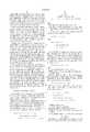
- FIG. 1is a block diagram of the transmission hardware and controller of the present invention
- FIG. 2is a flowchart of the method for controlling the hydraulic line pressure
- FIG. 3is a flowchart of an open loop control methodology of the present invention.
- FIG. 4is a flowchart of a method for reacting to clutch slip according to the present invention.
- FIG. 5is a flowchart of a method of determining a desired pressure according to the present invention.
- transmission hardware 100is connected to an operatively controlled by a transmission controller 102.
- the transmission hardware 100includes a regulator 104 interdisposed between a line pressure control (LPC) solenoid actuated valve 106, a pump 108, and a clutch and valve transmission subassembly 110.
- LPCline pressure control
- a pressure transducer 112is operatively disposed adjacent the subassembly 110 so as to detect the hydraulic line pressure throughout the hydraulic system interconnecting the regulator 104, LPC 106, pump 108 and subassembly 110.
- the pressure transducer 112is electrically coupled to a digital controller 114 of the transmission controller 102. As such, a signal representative of the pressure within the transmission hydraulic system may be communicated to the digital controller 114 for further processing.
- a target pressure generator 116communicates with the digital controller 114.
- the target pressure generator 116delivers a signal to the digital controller 114 indicative of a desired pressure for the transmission hydraulic system.
- the desired pressurechanges depending on the specific operating parameters of the vehicle.
- the output of the target pressure generator 116is based on various operational inputs such as engine speed, turbine speed, output speed, throttle, MAP, etc.
- the target pressure generator 116delivers the target pressure value to the digital controller 114.
- the digital controller 114compares the target pressure from the target pressure generator 116 to the actual pressure as read by the transducer 112. Based upon this difference, the digital controller 114 varies the setting of the LPC 106 which varies the fluid flow and pressure through the regulator 104 from the pump 108 to the subassembly 110. As such, the pressure within the hydraulic system is varied. As described in greater detail below, the digital controller 114 may continue to operate in this closed loop mode or may also operate in an open loop mode to control the hydraulic pressure.
- the pressure transducer 112continues to send actual pressure readings to the digital controller 114 which compares them to the target pressure determined by the target pressure generator 116 based on system inputs.
- the digital controller 114controls the LPC 106 based on a pre-selected schedule of LPC settings.
- the present inventionprovides for adaptive control of hydraulic line pressure to the multi-clutch assembly 110 and various clutches therein during operation of all forward gears.
- This line pressure controlis active except during shifts and EMCC operation or partial lock-up (PLU) of the torque converter when a preset hydraulic line pressure is maintained.
- PLUpartial lock-up
- the methodcontinuously controls hydraulic line pressure to a target level based upon instantaneous torque and shift requirements.
- the method of controlling transmission fluid line pressureuses negative feedback control. Based on the voltage input from the transducer 112, a "Duty Cycle” (DC) output is calculated.
- the DC outputproduces an electric current through the LPC valve 106 which varies fluid flow to the regulator valve 104 controlling line pressure.
- duty cycleis defined as the percent of time the LPC valve 106 is energized over a given time period such as 14 msec.
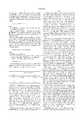
- FIG. 2a flowchart of the method for controlling the hydraulic line pressure and the transmission according to the present invention is illustrated.
- the methodologyis run periodically as called for by the transmission controller 102, for instance, every seven milliseconds.
- the methodologyenters at bubble 10 and falls through to block 12 where the actual pressure (P) within a hydraulic line is read from the transducer 112. From block 12, the methodology continues to decision block 14 where it determines whether the actual pressure P is within an acceptable operating range. For instance, the actual pressure should be below 250 and above 25 PSI during normal operation.
- the methodologydetermines if the value within the fault counter is greater than a preselected limit. This fault counter limit establishes an acceptable tolerance for the control methodology. If the fault counter value is less than the limit at decision block 18, or if the actual pressure is within the acceptable operating range in decision block 14, the methodology continues to block 20. In block 20, the methodology computes a difference (E) between the actual pressure (P) and the desired pressure (P*):
- the desired pressure levelis determined by the electronic transmission controller 102 based upon the torque and shift requirements of the transmission under current operating conditions (i.e., feedback).
- FIG. 5depicts a flowchart of a method for determining a desired pressure P* for a given set of environmental conditions according to the present invention.
- THRis the current throttle angle position sensor reading.
- the methodologycontinues to decision block 78 and determines if the torque converter clutch is engaged. If the torque converter clutch is engaged at decision block 78, the methodology continues to block 80. In block 80, the methodology calculates the desired pressure P* based on net engine torque which, in this case, is equal to turbine torque T t :
- K tca gain factor based on torque capacity
- MLPa minimum line pressure adjustment value
- T tTurbine Torque.
- the methodologycalculates desired pressure P* based on turbine torque and a constant:
- N eEngine speed in revolutions per minute
- N tTorque converter turbine speed in revolutions per minute
- P* maxis defined to be the maximum operating pressure of transmission. P* is set to P* max under all special conditions that require a consistent high line pressure level.
- the minimum operating pressureis set as follows:
- P lowMinimum achievable pressure dependent upon transmission hardware.
- the LPC valve 106 preferably used in the present inventionhas an operating range of approximately 0-50% duty cycle. Running the solenoid 106 at duty cycle values above the saturation point (DC max ) is undesirable and unnecessary since the only effect is to dissipate more power in the driver circuit, generating additional heat and reducing durability.
- DC maxis dependent upon the voltage across the coil and temperature. Based on data submitted by the solenoid supplier, a relationship is defined for DC max vs. voltage and temperature. Since the relationship is non-linear, the table is used to approximate DC max for a transmission temperature range between 0-300° F. and battery voltage range between 10-16 volts. Linear interpolation is used between table data points.
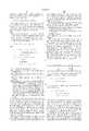
- FIG. 4a flowchart of a method for determining a clutch slip occurrence according to the present invention is illustrated.
- the systemthen returns to normal closed-loop control but with the minimum desired pressure increased slightly with use of the variable "MLP" in the calculation of desired pressure P*.
- MLPis "Minimum Line Pressure" adjustment amount and is used to compensate for clutch slippage when in-gear.
- the method for clutch slip controlenters at bubble 50 and falls through to block 52 where the slip counter is decremented at key-on start-up if the slip counter does not equal zero.
- the methodologycontinues to decision block 54 to determine if the torque converter clutch is fully engaged. If the torque converter clutch is not fully engaged at decision block 54, the methodology continues to decision block 56 to determine if the turbine and output shaft speeds are within an allowable ratio. For instance, since output speed times gear ratio equals turbine speed, the measured turbine speed should be within a tolerance of about 30 rpm. If the turbine and output shaft speeds are within the allowable ratio, the methodology advances from decision block 56 to block 58 and clears the clutch slip flag. However, if the turbine and output shaft speeds are outside of the allowable ratio, the methodology advances from decision block 56 to decision block 60.
- decision block 62the methodology determines if the engine rpm is greater than the turbine speed plus a tolerance factor such as 50 rpm. If the engine rpm is not greater than the turbine speed plus the tolerance factor at decision block 52, the methodology advances to block 58 and clears the slip clutch flag. However, if the engine rpm is greater than the turbine speed plus the tolerance factor at decision block 62, the methodology advances to decision block 60.
- the methodologydetermines if it is operating in open loop control. If not, the methodology continues to block 64 and increments the slip counter to the value PC. However, if the methodology is operating in open loop control at decision block 60, the methodology continues to block 66 and increments the slip counter to the value OLPC. OLPC is "Open Loop Pressure Count" and compensates for clutch slippage when in-gear and open loop. After incrementing the slip counter at either block 64 or block 66, the methodology advances to block 68 and sets the clutch slip flag. After setting the clutch slip flag at block 68, or clearing the clutch slip flag at block 58, the flag setting is used in the decision block 28 of FIG. 2. Thereafter, the methodology exits the routine at 70.
- the methodology described above with respect to FIG. 4may also be represented mathematically as follows.
- the transmission controllercontrols the LPC valve 106 according to the following control equation which may be performed at 7 msec intervals(i):
- DC(i)current calculated DC to be output to the LPC valve which is inversely proportional to line pressure
- DC maxMaximum duty cycle based on operating range of the LPC valve
- the effect of decrementing MLPis to lower line pressure for all conditions.
- the desired line pressure, P*is deliberately biased so that slip will only occur at light throttle (e.g. ⁇ 20%). This ensures that the slip will be so slight that no noticeable disturbance occurs.
- the methodologyadvances to block 30 and sets the duty cycle output to the minimum duty cycle DC min . If the clutch slip flag is not set at decision block 28, the methodology continues to block 32 and uses the duty cycle output computed from block 24. After setting the duty cycle to the appropriate value in block 30 or 32, the methodology continues to bubble 34 where it exits the routine pending a return therethrough upon demand by the transmission controller.
- the methodologyadvances from decision block 18 to block 36 and stores the diagnostic fault.
- a sensor diagnostic testis used to detect an open or short in the pressure transducer circuit. This test runs every program loop time (7 msec). If a problem is detected, the failure is reported to diagnostics and testing of the circuit is continued for recovery.
- the Sensor Fault (SLFT) flagis set if the sensor fault counter SFCTR>200.
- the SLFT flagis cleared if SFCTR ⁇ 180.
- the counteris incremented as follows:
- SFCTRSFCTR+8, if analog to digital convertor (A/D) input voltage outside operating range,
- SFCTRSFCTR-1, if A/D input voltage within operating range
- the methodologyAfter reporting the failure condition to diagnostics at block 36, the methodology continues to block 38 and implements open loop control of the system which is illustrated in FIG. 3.
- the LPC valve 106if the signal from the transducer 112 becomes unreliable due to an electrical circuit failure, the LPC valve 106 is operated at a duty cycle which produces pressures at or near maximum desired pressure (P* max ), i.e., open loop control (no feedback).
- P* maxmaximum desired pressure
- the methodologylooks up DC Temp based on temperature and desired pressure.
- DC Tempis based on test data taken over a temperature range of 40° F. to 300° F. with linear interpolation used between table data points:
- OLPCis incremented by 8 when clutch slippage is detected and decremented by 1 each time vehicle is started and is limited, OLPC ⁇ 64.
- the DC outputis based upon test data, voltage compensation, and occurrence of clutch slip. From block 44, the methodology continues to block 46 and outputs DC OL . From block 46 the methodology falls through to bubble 48 and exits the subroutine.
- a malfunction of the line pressure control systemis determined from operating outside the acceptable control window and not achieving desired pressure level as defined below.
- the methodologyreports a system failed low condition to Diagnostics. If the LPFF is set, the methodology reports a system off-target condition to Diagnostics. If the LPHF is set, the methodology reports a system failed high condition to Diagnostics. It should be noted that the methodology does not check for the Line Pressure Low Flag (LPLF) or Line Pressure Fault Flag (LPFF) during shut down, during the first 10 seconds after startup, when engine RPM ⁇ (14 ⁇ P*), or while performing special system functions. When a fault flag is set, pressure control is again maintained through an open loop strategy as described above.
- LPLFLine Pressure Low Flag
- LPFFLine Pressure Fault Flag
- the primary benefit of the improved control systemis a reduction of pump pressure to the minimum required level which reduces parasitic losses to a minimum and improves fuel economy. Additionally, the fixed line pressure levels during shifts can be optimized providing consistent shift quality.
Landscapes
- Engineering & Computer Science (AREA)
- General Engineering & Computer Science (AREA)
- Mechanical Engineering (AREA)
- Control Of Transmission Device (AREA)
Abstract
Description
E=measured pressure (P)-desired pressure (P*).
P*.sub.B =2(THR.sub.s -17°), P*.sub.B ≦0 psi
P*=K.sub.tc (1+MLP/64)T.sub.t +P*.sub.B +ΔP*.sub.THR,
P*=15+K.sub.tc (1+MLP/64)T.sub.t +P*.sub.B +ΔP*.sub.THR.
P*.sub.min =P.sub.low [1+MLP(i)/64]+ΔP*.sub.THR
δDC=G[-δDC(I-1)+0.39E(I)-0.28E(I-1)]
DC(I)=DC(I-1)+δDC
______________________________________ BATTERY VOLTAGE TEMP ° F. 10 V . . . 16 V ______________________________________ 0° DC.sub.maxll . . . DC.sub.maxml . . . . . . . . . . . . 300° DC.sub.maxln . . . DC.sub.maxmn ______________________________________
DC(i)=DC(i-1)+δDC(i); Limit DC.sub.min ≦DC≦DC.sub.max.
δDC(i)=G[-δDC(i-1)+C.sub.G1 E(i)-C.sub.G2 E(i-1)]
______________________________________ Temperature (° F.) DC.sub.Temp ______________________________________ 40°DC.sub.Temp1 0°DC.sub.Temp2 300E DC.sub.Temp3 ______________________________________
Claims (16)
Priority Applications (1)
| Application Number | Priority Date | Filing Date | Title |
|---|---|---|---|
| US09/168,836US6022293A (en) | 1998-10-08 | 1998-10-08 | Electronic control of transmission line pressure |
Applications Claiming Priority (1)
| Application Number | Priority Date | Filing Date | Title |
|---|---|---|---|
| US09/168,836US6022293A (en) | 1998-10-08 | 1998-10-08 | Electronic control of transmission line pressure |
Publications (1)
| Publication Number | Publication Date |
|---|---|
| US6022293Atrue US6022293A (en) | 2000-02-08 |
Family
ID=22613138
Family Applications (1)
| Application Number | Title | Priority Date | Filing Date |
|---|---|---|---|
| US09/168,836Expired - LifetimeUS6022293A (en) | 1998-10-08 | 1998-10-08 | Electronic control of transmission line pressure |
Country Status (1)
| Country | Link |
|---|---|
| US (1) | US6022293A (en) |
Cited By (37)
| Publication number | Priority date | Publication date | Assignee | Title |
|---|---|---|---|---|
| EP1150031A1 (en)* | 2000-04-27 | 2001-10-31 | Eaton Corporation | A self-calibrating system and method for controlling a hydraulically operated device |
| US6471613B1 (en) | 2000-08-23 | 2002-10-29 | Daimlerchrysler Corporation | Transmission with variable line pressure |
| US6514175B2 (en)* | 2000-05-19 | 2003-02-04 | Toyota Jidosha Kabushiki Kaisha | Hydraulic control system for transmissions |
| US6537181B2 (en)* | 2000-03-08 | 2003-03-25 | Mitsubishi Jidosha Kogyo Kabushiki Kaisha | Clutch control device and method for use in continuously variable transmission |
| US20030064849A1 (en)* | 2001-09-28 | 2003-04-03 | Jatco Ltd | Hydraulic control device for automatic transmission |
| WO2003048614A1 (en)* | 2001-12-04 | 2003-06-12 | Zf Friedrichshafen Ag | Method for controlling a pressure supply device in a hydraulic circuit |
| FR2834034A1 (en)* | 2001-12-20 | 2003-06-27 | Renault | METHOD FOR CONTROLLING AN AUTOMATED TRANSMISSION WITH STAGE REPORTS |
| US6675079B2 (en)* | 2000-12-30 | 2004-01-06 | Hyundai Motor Company | Fault diagnosis method for an input shaft speed sensor of an automatic transmission |
| US20040005956A1 (en)* | 2002-07-08 | 2004-01-08 | Beong-Yeol You | Hydraulic control system for an automatic transmission |
| US6679800B1 (en)* | 1999-10-18 | 2004-01-20 | Nissan Motor Co., Ltd. | Hydraulic pressure control method and apparatus of an automatic transmission for a vehicle |
| EP1411277A1 (en)* | 2002-10-16 | 2004-04-21 | Van Doorne's Transmissie B.V. | Gearshift control method for an automatic transmission and automatic transmission operated in accordance therewith |
| US20040106501A1 (en)* | 2001-04-18 | 2004-06-03 | Otto Lutz | Gearbox control system |
| US20040106497A1 (en)* | 2002-12-02 | 2004-06-03 | Toyota Jidosha Kabushiki Kaisha | Shift control apparatus and shift control method for a vehicular automatic transmission |
| US6875156B1 (en)* | 2002-09-27 | 2005-04-05 | Michael Steiger | Transmission controller and a method of use |
| US20050107213A1 (en)* | 2003-11-17 | 2005-05-19 | Kim Joung C. | Line pressure variable control method and system for an automatic transmission |
| US20050283297A1 (en)* | 2004-06-22 | 2005-12-22 | Eaton Corporation (Rj) | Closed-loop, valve-based transmission control algorithum |
| CN100346247C (en)* | 2003-01-28 | 2007-10-31 | 姚福来 | Method for controlling operating efficiency of water pump fan for industrial controller and configuration software |
| US20070288148A1 (en)* | 2006-06-08 | 2007-12-13 | Weijia Cui | Adaptive Open Loop Line Pressure Control Of Hydraulic Fluid In An Automatic Transmission |
| US20080082242A1 (en)* | 2006-10-03 | 2008-04-03 | Dell Eva Mark L | Mode selection and switching logic in a closed-loop pulse width modulation valve-based transmission control system |
| US20080176709A1 (en)* | 2007-01-24 | 2008-07-24 | Wu Peter E | Method and apparatus to monitor devices of a hydraulic circuit of an electro-mechanical transmission |
| US20080176706A1 (en)* | 2007-01-24 | 2008-07-24 | Wu Peter E | Method and apparatus to control operation of an electro-mechanical transmission |
| CN100432881C (en)* | 2002-12-24 | 2008-11-12 | 姚福来 | Water pump fan running efficiency controlling method for speeder |
| CN100458170C (en)* | 2003-01-28 | 2009-02-04 | 姚福来 | Method and apparatus for controlling operating efficiency of water pump fan of control speed regulator |
| US20090065719A1 (en)* | 2007-09-06 | 2009-03-12 | Stoever Guy T | Electrically controlled pilot operated pressure regulator valve apparatus and method of operation of the same |
| US20090112423A1 (en)* | 2007-10-29 | 2009-04-30 | Gm Global Technology Operations, Inc. | Method and apparatus to control operation of a hydraulic pump for an electro-mechanical transmission |
| US20090111644A1 (en)* | 2007-10-25 | 2009-04-30 | Gm Global Technology Operations, Inc. | Method and apparatus for clutch torque control in mode and fixed gear for a hybrid powertrain system |
| US20090112421A1 (en)* | 2007-10-26 | 2009-04-30 | Gm Global Technology Operations, Inc. | Method and apparatus to control hydraulic line pressure in an electro-mechanical transmission |
| US20090112429A1 (en)* | 2007-10-26 | 2009-04-30 | Gm Global Technology Operations, Inc. | Method and apparatus to control clutch pressures in an electro-mechanical transmission |
| US20090107135A1 (en)* | 2007-10-31 | 2009-04-30 | Sauer-Danfoss Inc. | Low power hmt with by-pass valve |
| US8275530B2 (en) | 2010-09-20 | 2012-09-25 | Sonnax Industries, Inc. | Apparatus and method for increasing transmission line fluid pressure |
| US20130253787A1 (en)* | 2012-03-26 | 2013-09-26 | Cnh America Llc | System and method for controlling the pressure of hydraulic fluid supplied within a work vehicle transmission |
| US8548699B2 (en) | 2010-05-25 | 2013-10-01 | GM Global Technology Operations LLC | Control system and method for adaptive control of transmission fluid operating pressures |
| CN103671885A (en)* | 2012-09-14 | 2014-03-26 | 福特全球技术公司 | Line pressure control with input shaft torque measurement |
| CN101270755B (en)* | 2008-05-11 | 2014-05-21 | 姚福来 | Timing and switching method for controlling water pump fan parallel-connection energy-saving operation |
| US20140358390A1 (en)* | 2013-06-04 | 2014-12-04 | Infineon Technologies Ag | Direct clutch slip control |
| US20150260278A1 (en)* | 2012-12-26 | 2015-09-17 | Aisin Aw Co., Ltd. | Hydraulic control device for automatic transmission |
| CN111946466A (en)* | 2020-07-06 | 2020-11-17 | 江苏大学 | A dual-fuel engine methanol pressure regulating system and control method thereof |
Citations (17)
| Publication number | Priority date | Publication date | Assignee | Title |
|---|---|---|---|---|
| US3631744A (en)* | 1969-12-22 | 1972-01-04 | Chrysler Corp | Hydrodynamic transmission |
| US3956947A (en)* | 1974-06-14 | 1976-05-18 | Chrysler Corporation | Adaptive control system for automatic transmission |
| US4106367A (en)* | 1974-10-07 | 1978-08-15 | Regie Nationale Des Usines Renault | Pressure control apparatus for the automatic transmission of automotive vehicles |
| US4289048A (en)* | 1978-09-11 | 1981-09-15 | Chrysler Corporation | Lock-up system for torque converter |
| US4505368A (en)* | 1981-09-18 | 1985-03-19 | Robert Bosch Gmbh | Operator-controlled automotive gear or transmission change system |
| US4781080A (en)* | 1986-01-07 | 1988-11-01 | Toyota Jidosha Kabushiki Kaisha | Hydraulic pressure control device in automatic transmission |
| US4836055A (en)* | 1987-04-13 | 1989-06-06 | Fuji Jukogyo Kabushiki Kaisha | System for controlling a line pressure in an automatic transmission for motor vehicles |
| US4875391A (en)* | 1988-04-29 | 1989-10-24 | Chrysler Motors Corporation | Electronically-controlled, adaptive automatic transmission system |
| US5060540A (en)* | 1989-05-19 | 1991-10-29 | Nissan Motor Co., Ltd. | Line pressure control based on learning of quality of shifting in automatic transmission |
| US5074167A (en)* | 1989-10-19 | 1991-12-24 | Mazda Motor Corporation | Automatic transmission |
| US5093789A (en)* | 1989-01-10 | 1992-03-03 | Mazda Motor Corporation | Oil pressure control systems for automatic transmissions |
| US5103692A (en)* | 1990-06-08 | 1992-04-14 | Nissan Motor Co., Ltd. | Automatic transmission and engine control system |
| US5305663A (en)* | 1992-08-10 | 1994-04-26 | Ford Motor Company | Automatic transmission control system |
| US5449329A (en)* | 1993-07-20 | 1995-09-12 | Deere & Company | Method for controlling transmission control clutches |
| US5458545A (en)* | 1994-01-21 | 1995-10-17 | Chrysler Corporation | Adaptive line pressure control for an electronic automatic transmission |
| US5630773A (en)* | 1996-02-02 | 1997-05-20 | Eaton Corporation | Method and apparatus for slip mode control of automatic clutch |
| US5803869A (en)* | 1997-03-17 | 1998-09-08 | General Motors Corporation | Automatic transmission auto neutral clutch controls with intermittent slip and a method of control |
- 1998
- 1998-10-08USUS09/168,836patent/US6022293A/ennot_activeExpired - Lifetime
Patent Citations (17)
| Publication number | Priority date | Publication date | Assignee | Title |
|---|---|---|---|---|
| US3631744A (en)* | 1969-12-22 | 1972-01-04 | Chrysler Corp | Hydrodynamic transmission |
| US3956947A (en)* | 1974-06-14 | 1976-05-18 | Chrysler Corporation | Adaptive control system for automatic transmission |
| US4106367A (en)* | 1974-10-07 | 1978-08-15 | Regie Nationale Des Usines Renault | Pressure control apparatus for the automatic transmission of automotive vehicles |
| US4289048A (en)* | 1978-09-11 | 1981-09-15 | Chrysler Corporation | Lock-up system for torque converter |
| US4505368A (en)* | 1981-09-18 | 1985-03-19 | Robert Bosch Gmbh | Operator-controlled automotive gear or transmission change system |
| US4781080A (en)* | 1986-01-07 | 1988-11-01 | Toyota Jidosha Kabushiki Kaisha | Hydraulic pressure control device in automatic transmission |
| US4836055A (en)* | 1987-04-13 | 1989-06-06 | Fuji Jukogyo Kabushiki Kaisha | System for controlling a line pressure in an automatic transmission for motor vehicles |
| US4875391A (en)* | 1988-04-29 | 1989-10-24 | Chrysler Motors Corporation | Electronically-controlled, adaptive automatic transmission system |
| US5093789A (en)* | 1989-01-10 | 1992-03-03 | Mazda Motor Corporation | Oil pressure control systems for automatic transmissions |
| US5060540A (en)* | 1989-05-19 | 1991-10-29 | Nissan Motor Co., Ltd. | Line pressure control based on learning of quality of shifting in automatic transmission |
| US5074167A (en)* | 1989-10-19 | 1991-12-24 | Mazda Motor Corporation | Automatic transmission |
| US5103692A (en)* | 1990-06-08 | 1992-04-14 | Nissan Motor Co., Ltd. | Automatic transmission and engine control system |
| US5305663A (en)* | 1992-08-10 | 1994-04-26 | Ford Motor Company | Automatic transmission control system |
| US5449329A (en)* | 1993-07-20 | 1995-09-12 | Deere & Company | Method for controlling transmission control clutches |
| US5458545A (en)* | 1994-01-21 | 1995-10-17 | Chrysler Corporation | Adaptive line pressure control for an electronic automatic transmission |
| US5630773A (en)* | 1996-02-02 | 1997-05-20 | Eaton Corporation | Method and apparatus for slip mode control of automatic clutch |
| US5803869A (en)* | 1997-03-17 | 1998-09-08 | General Motors Corporation | Automatic transmission auto neutral clutch controls with intermittent slip and a method of control |
Cited By (68)
| Publication number | Priority date | Publication date | Assignee | Title |
|---|---|---|---|---|
| US6679800B1 (en)* | 1999-10-18 | 2004-01-20 | Nissan Motor Co., Ltd. | Hydraulic pressure control method and apparatus of an automatic transmission for a vehicle |
| US6537181B2 (en)* | 2000-03-08 | 2003-03-25 | Mitsubishi Jidosha Kogyo Kabushiki Kaisha | Clutch control device and method for use in continuously variable transmission |
| DE10110920B4 (en)* | 2000-03-08 | 2009-12-17 | Mitsubishi Jidosha Kogyo K.K. | Clutch control device and method for its use in a continuously variable transmission |
| US6341552B1 (en) | 2000-04-27 | 2002-01-29 | Eaton Corporation | Self-calibrating system and method for controlling a hydraulically operated device |
| AU773739B2 (en)* | 2000-04-27 | 2004-06-03 | Eaton Corporation | A self-calibrating system and method for controlling a hydraulically operated device |
| EP1150031A1 (en)* | 2000-04-27 | 2001-10-31 | Eaton Corporation | A self-calibrating system and method for controlling a hydraulically operated device |
| US6514175B2 (en)* | 2000-05-19 | 2003-02-04 | Toyota Jidosha Kabushiki Kaisha | Hydraulic control system for transmissions |
| US6471613B1 (en) | 2000-08-23 | 2002-10-29 | Daimlerchrysler Corporation | Transmission with variable line pressure |
| CN1307379C (en)* | 2000-12-30 | 2007-03-28 | 现代自动车株式会社 | Fault diagnostic method for drive shaft speed sensor with automatic transmission |
| US6675079B2 (en)* | 2000-12-30 | 2004-01-06 | Hyundai Motor Company | Fault diagnosis method for an input shaft speed sensor of an automatic transmission |
| US7131931B2 (en)* | 2001-04-18 | 2006-11-07 | Zf Friedrichshafen Ag | Gearbox control system |
| US20040106501A1 (en)* | 2001-04-18 | 2004-06-03 | Otto Lutz | Gearbox control system |
| EP1298360A3 (en)* | 2001-09-28 | 2005-03-02 | JATCO Ltd | Hydraulic control method and device for automatic transmissions |
| US20030064849A1 (en)* | 2001-09-28 | 2003-04-03 | Jatco Ltd | Hydraulic control device for automatic transmission |
| WO2003048614A1 (en)* | 2001-12-04 | 2003-06-12 | Zf Friedrichshafen Ag | Method for controlling a pressure supply device in a hydraulic circuit |
| US20050002796A1 (en)* | 2001-12-04 | 2005-01-06 | Thomas Knoblauch | Method for controlling a pressure supply device in a hydraulic circuit |
| US7073328B2 (en) | 2001-12-04 | 2006-07-11 | Zf Friedrichshafen Ag | Method for controlling a pressure supply device in a hydraulic circuit |
| FR2834034A1 (en)* | 2001-12-20 | 2003-06-27 | Renault | METHOD FOR CONTROLLING AN AUTOMATED TRANSMISSION WITH STAGE REPORTS |
| US6832977B2 (en) | 2002-07-08 | 2004-12-21 | Hyundai Motor Company | Hydraulic control system for an automatic transmission |
| DE10260340B4 (en)* | 2002-07-08 | 2009-12-03 | Hyundai Motor Company | System and method for hydraulic control of a motor vehicle automatic transmission |
| US20040005956A1 (en)* | 2002-07-08 | 2004-01-08 | Beong-Yeol You | Hydraulic control system for an automatic transmission |
| US6875156B1 (en)* | 2002-09-27 | 2005-04-05 | Michael Steiger | Transmission controller and a method of use |
| EP1411277A1 (en)* | 2002-10-16 | 2004-04-21 | Van Doorne's Transmissie B.V. | Gearshift control method for an automatic transmission and automatic transmission operated in accordance therewith |
| US20040106497A1 (en)* | 2002-12-02 | 2004-06-03 | Toyota Jidosha Kabushiki Kaisha | Shift control apparatus and shift control method for a vehicular automatic transmission |
| US6931315B2 (en)* | 2002-12-02 | 2005-08-16 | Toyota Jidosha Kabushiki Kaisha | Shift control apparatus and shift control method for a vehicular automatic transmission |
| CN1304771C (en)* | 2002-12-02 | 2007-03-14 | 丰田自动车株式会社 | Shift control apparatus and shift control method for a vehicular automatic transmission |
| CN100432881C (en)* | 2002-12-24 | 2008-11-12 | 姚福来 | Water pump fan running efficiency controlling method for speeder |
| CN100458170C (en)* | 2003-01-28 | 2009-02-04 | 姚福来 | Method and apparatus for controlling operating efficiency of water pump fan of control speed regulator |
| CN100346247C (en)* | 2003-01-28 | 2007-10-31 | 姚福来 | Method for controlling operating efficiency of water pump fan for industrial controller and configuration software |
| US20050107213A1 (en)* | 2003-11-17 | 2005-05-19 | Kim Joung C. | Line pressure variable control method and system for an automatic transmission |
| US7164981B2 (en) | 2003-11-17 | 2007-01-16 | Hyundai Motor Company | Line pressure variable control method and system for an automatic transmission |
| US20050283297A1 (en)* | 2004-06-22 | 2005-12-22 | Eaton Corporation (Rj) | Closed-loop, valve-based transmission control algorithum |
| US7194349B2 (en)* | 2004-06-22 | 2007-03-20 | Eaton Corporation | Closed-loop, valve-based transmission control algorithum |
| US20070288148A1 (en)* | 2006-06-08 | 2007-12-13 | Weijia Cui | Adaptive Open Loop Line Pressure Control Of Hydraulic Fluid In An Automatic Transmission |
| US20080082242A1 (en)* | 2006-10-03 | 2008-04-03 | Dell Eva Mark L | Mode selection and switching logic in a closed-loop pulse width modulation valve-based transmission control system |
| US20080176709A1 (en)* | 2007-01-24 | 2008-07-24 | Wu Peter E | Method and apparatus to monitor devices of a hydraulic circuit of an electro-mechanical transmission |
| US7670254B2 (en)* | 2007-01-24 | 2010-03-02 | Gm Global Technology Operations, Inc. | Method and apparatus to monitor devices of a hydraulic circuit of an electro-mechanical transmission |
| US20080176706A1 (en)* | 2007-01-24 | 2008-07-24 | Wu Peter E | Method and apparatus to control operation of an electro-mechanical transmission |
| US7648440B2 (en) | 2007-01-24 | 2010-01-19 | Gm Global Technology Operations, Inc. | Method and apparatus to control operation of an electro-mechanical transmission |
| US8910657B2 (en) | 2007-09-06 | 2014-12-16 | Cnh Industrial America Llc | Electrically controlled pilot operated pressure regulator valve apparatus and method of operation of the same |
| US20090065719A1 (en)* | 2007-09-06 | 2009-03-12 | Stoever Guy T | Electrically controlled pilot operated pressure regulator valve apparatus and method of operation of the same |
| US20090111644A1 (en)* | 2007-10-25 | 2009-04-30 | Gm Global Technology Operations, Inc. | Method and apparatus for clutch torque control in mode and fixed gear for a hybrid powertrain system |
| US8187145B2 (en)* | 2007-10-25 | 2012-05-29 | GM Global Technology Operations LLC | Method and apparatus for clutch torque control in mode and fixed gear for a hybrid powertrain system |
| US20090112421A1 (en)* | 2007-10-26 | 2009-04-30 | Gm Global Technology Operations, Inc. | Method and apparatus to control hydraulic line pressure in an electro-mechanical transmission |
| EP2053279A3 (en)* | 2007-10-26 | 2012-03-21 | GM Global Technology Operations LLC | Method and apparatus to control clutch pressures in an electro-mechanical transmission |
| US20090112429A1 (en)* | 2007-10-26 | 2009-04-30 | Gm Global Technology Operations, Inc. | Method and apparatus to control clutch pressures in an electro-mechanical transmission |
| US8560191B2 (en) | 2007-10-26 | 2013-10-15 | GM Global Technology Operations LLC | Method and apparatus to control clutch pressures in an electro-mechanical transmission |
| US9097337B2 (en)* | 2007-10-26 | 2015-08-04 | GM Global Technology Operations LLC | Method and apparatus to control hydraulic line pressure in an electro-mechanical transmission |
| US20090112423A1 (en)* | 2007-10-29 | 2009-04-30 | Gm Global Technology Operations, Inc. | Method and apparatus to control operation of a hydraulic pump for an electro-mechanical transmission |
| US8170762B2 (en)* | 2007-10-29 | 2012-05-01 | GM Global Technology Operations LLC | Method and apparatus to control operation of a hydraulic pump for an electro-mechanical transmission |
| US7730722B2 (en) | 2007-10-31 | 2010-06-08 | Sauer-Danfoss Inc. | Low power HMT with by-pass valve |
| US20090107135A1 (en)* | 2007-10-31 | 2009-04-30 | Sauer-Danfoss Inc. | Low power hmt with by-pass valve |
| CN101270755B (en)* | 2008-05-11 | 2014-05-21 | 姚福来 | Timing and switching method for controlling water pump fan parallel-connection energy-saving operation |
| US8548699B2 (en) | 2010-05-25 | 2013-10-01 | GM Global Technology Operations LLC | Control system and method for adaptive control of transmission fluid operating pressures |
| US8275530B2 (en) | 2010-09-20 | 2012-09-25 | Sonnax Industries, Inc. | Apparatus and method for increasing transmission line fluid pressure |
| US20130253787A1 (en)* | 2012-03-26 | 2013-09-26 | Cnh America Llc | System and method for controlling the pressure of hydraulic fluid supplied within a work vehicle transmission |
| US8958963B2 (en)* | 2012-03-26 | 2015-02-17 | Cnh Industrial America Llc | System and method for controlling the pressure of hydraulic fluid supplied within a work vehicle transmission |
| EP2644948A3 (en)* | 2012-03-26 | 2017-11-29 | CNH Industrial Italia S.p.A. | System and method for controlling the pressure of hydraulic fluid supplied within a work vehicle transmission |
| CN103671885A (en)* | 2012-09-14 | 2014-03-26 | 福特全球技术公司 | Line pressure control with input shaft torque measurement |
| US9488267B2 (en)* | 2012-09-14 | 2016-11-08 | Ford Global Technologies, Llc | Line pressure control with input shaft torque measurement |
| CN103671885B (en)* | 2012-09-14 | 2017-09-29 | 福特全球技术公司 | The loine pressure control measured using input shaft torque |
| US20150260278A1 (en)* | 2012-12-26 | 2015-09-17 | Aisin Aw Co., Ltd. | Hydraulic control device for automatic transmission |
| US9458927B2 (en)* | 2012-12-26 | 2016-10-04 | Aisin Aw Co., Ltd. | Hydraulic control device for automatic transmission |
| US20140358390A1 (en)* | 2013-06-04 | 2014-12-04 | Infineon Technologies Ag | Direct clutch slip control |
| US9097345B2 (en)* | 2013-06-04 | 2015-08-04 | Infineon Technologies Ag | Direct clutch slip control |
| US10174837B2 (en) | 2013-06-04 | 2019-01-08 | Infineon Technologies Ag | Direct clutch slip control |
| CN111946466A (en)* | 2020-07-06 | 2020-11-17 | 江苏大学 | A dual-fuel engine methanol pressure regulating system and control method thereof |
| CN111946466B (en)* | 2020-07-06 | 2022-06-21 | 江苏大学 | A dual-fuel engine methanol pressure regulating system and control method thereof |
Similar Documents
| Publication | Publication Date | Title |
|---|---|---|
| US6022293A (en) | Electronic control of transmission line pressure | |
| US5458545A (en) | Adaptive line pressure control for an electronic automatic transmission | |
| US4805750A (en) | Steady state slip detection/correction for a motor vehicle transmission | |
| US6813551B2 (en) | Control apparatus for continuously variable transmission | |
| US6928357B2 (en) | Torque-converter slip control system | |
| US4793454A (en) | Continuously variable transmission clutch control system | |
| EP0424005A2 (en) | Line pressure control system for a continuously variable transmission | |
| EP1217264A2 (en) | Slip control system for lock-up clutch of a torque converter | |
| US5719768A (en) | Lock-up clutch control method | |
| US7346442B2 (en) | Lockup control of torque converter | |
| EP0525853B1 (en) | A method of operation for an automatic transmission | |
| US6066072A (en) | Torque converter relative rotation control device | |
| US20040082434A1 (en) | Engaging force control of lockup clutch | |
| US6049750A (en) | Speed change ratio controller for continuously variable transmission | |
| US5289741A (en) | Adaptive transmission pressure control with run-through detection | |
| US7039516B2 (en) | Belt type continuously variable transmission | |
| US5089964A (en) | Hydraulic transmission control system | |
| US20070288148A1 (en) | Adaptive Open Loop Line Pressure Control Of Hydraulic Fluid In An Automatic Transmission | |
| US5086665A (en) | Adaptive shift pressure characterization of an electronically controlled automatic transmission | |
| JPH05240331A (en) | Hydraulic control device for vehicle power transmission device | |
| EP0668456A2 (en) | Method and apparatus for controlling a gear change in an automatic transmission | |
| US5082095A (en) | Lock-up clutch pressure control device | |
| US6398693B1 (en) | Line pressure control unit of automatic transmission | |
| CN111692166B (en) | Method for controlling a hydraulic system | |
| JPH03181659A (en) | Controller for continuously variable transmission |
Legal Events
| Date | Code | Title | Description |
|---|---|---|---|
| AS | Assignment | Owner name:CHRYSLER CORPORATION, MICHIGAN Free format text:ASSIGNMENT OF ASSIGNORS INTEREST;ASSIGNORS:DOURRA, HUSSEIN A.;PARENTI, DAVID;LEISING, MAURICE B.;REEL/FRAME:009607/0110 Effective date:19981006 | |
| STCF | Information on status: patent grant | Free format text:PATENTED CASE | |
| FPAY | Fee payment | Year of fee payment:4 | |
| FPAY | Fee payment | Year of fee payment:8 | |
| AS | Assignment | Owner name:WILMINGTON TRUST COMPANY, DELAWARE Free format text:GRANT OF SECURITY INTEREST IN PATENT RIGHTS - FIRST PRIORITY;ASSIGNOR:CHRYSLER LLC;REEL/FRAME:019773/0001 Effective date:20070803 Owner name:WILMINGTON TRUST COMPANY,DELAWARE Free format text:GRANT OF SECURITY INTEREST IN PATENT RIGHTS - FIRST PRIORITY;ASSIGNOR:CHRYSLER LLC;REEL/FRAME:019773/0001 Effective date:20070803 | |
| AS | Assignment | Owner name:WILMINGTON TRUST COMPANY, DELAWARE Free format text:GRANT OF SECURITY INTEREST IN PATENT RIGHTS - SECOND PRIORITY;ASSIGNOR:CHRYSLER LLC;REEL/FRAME:019767/0810 Effective date:20070803 Owner name:WILMINGTON TRUST COMPANY,DELAWARE Free format text:GRANT OF SECURITY INTEREST IN PATENT RIGHTS - SECOND PRIORITY;ASSIGNOR:CHRYSLER LLC;REEL/FRAME:019767/0810 Effective date:20070803 | |
| AS | Assignment | Owner name:DAIMLERCHRYSLER CORPORATION, MICHIGAN Free format text:CHANGE OF NAME;ASSIGNOR:CHRYSLER CORPORATION;REEL/FRAME:021826/0034 Effective date:19981116 | |
| AS | Assignment | Owner name:CHRYSLER LLC, MICHIGAN Free format text:CHANGE OF NAME;ASSIGNOR:DAIMLERCHRYSLER COMPANY LLC;REEL/FRAME:021832/0233 Effective date:20070727 Owner name:DAIMLERCHRYSLER COMPANY LLC, MICHIGAN Free format text:CHANGE OF NAME;ASSIGNOR:DAIMLERCHRYSLER CORPORATION;REEL/FRAME:021832/0256 Effective date:20070329 | |
| AS | Assignment | Owner name:US DEPARTMENT OF THE TREASURY, DISTRICT OF COLUMBI Free format text:GRANT OF SECURITY INTEREST IN PATENT RIGHTS - THIR;ASSIGNOR:CHRYSLER LLC;REEL/FRAME:022259/0188 Effective date:20090102 Owner name:US DEPARTMENT OF THE TREASURY,DISTRICT OF COLUMBIA Free format text:GRANT OF SECURITY INTEREST IN PATENT RIGHTS - THIR;ASSIGNOR:CHRYSLER LLC;REEL/FRAME:022259/0188 Effective date:20090102 | |
| AS | Assignment | Owner name:CHRYSLER LLC, MICHIGAN Free format text:RELEASE BY SECURED PARTY;ASSIGNOR:US DEPARTMENT OF THE TREASURY;REEL/FRAME:022910/0273 Effective date:20090608 | |
| AS | Assignment | Owner name:CHRYSLER LLC, MICHIGAN Free format text:RELEASE OF SECURITY INTEREST IN PATENT RIGHTS - FIRST PRIORITY;ASSIGNOR:WILMINGTON TRUST COMPANY;REEL/FRAME:022910/0498 Effective date:20090604 Owner name:CHRYSLER LLC, MICHIGAN Free format text:RELEASE OF SECURITY INTEREST IN PATENT RIGHTS - SECOND PRIORITY;ASSIGNOR:WILMINGTON TRUST COMPANY;REEL/FRAME:022910/0740 Effective date:20090604 Owner name:NEW CARCO ACQUISITION LLC, MICHIGAN Free format text:ASSIGNMENT OF ASSIGNORS INTEREST;ASSIGNOR:CHRYSLER LLC;REEL/FRAME:022915/0001 Effective date:20090610 Owner name:THE UNITED STATES DEPARTMENT OF THE TREASURY, DIST Free format text:SECURITY AGREEMENT;ASSIGNOR:NEW CARCO ACQUISITION LLC;REEL/FRAME:022915/0489 Effective date:20090610 Owner name:CHRYSLER LLC,MICHIGAN Free format text:RELEASE OF SECURITY INTEREST IN PATENT RIGHTS - FIRST PRIORITY;ASSIGNOR:WILMINGTON TRUST COMPANY;REEL/FRAME:022910/0498 Effective date:20090604 Owner name:CHRYSLER LLC,MICHIGAN Free format text:RELEASE OF SECURITY INTEREST IN PATENT RIGHTS - SECOND PRIORITY;ASSIGNOR:WILMINGTON TRUST COMPANY;REEL/FRAME:022910/0740 Effective date:20090604 Owner name:NEW CARCO ACQUISITION LLC,MICHIGAN Free format text:ASSIGNMENT OF ASSIGNORS INTEREST;ASSIGNOR:CHRYSLER LLC;REEL/FRAME:022915/0001 Effective date:20090610 Owner name:THE UNITED STATES DEPARTMENT OF THE TREASURY,DISTR Free format text:SECURITY AGREEMENT;ASSIGNOR:NEW CARCO ACQUISITION LLC;REEL/FRAME:022915/0489 Effective date:20090610 | |
| AS | Assignment | Owner name:CHRYSLER GROUP LLC, MICHIGAN Free format text:CHANGE OF NAME;ASSIGNOR:NEW CARCO ACQUISITION LLC;REEL/FRAME:022919/0126 Effective date:20090610 Owner name:CHRYSLER GROUP LLC,MICHIGAN Free format text:CHANGE OF NAME;ASSIGNOR:NEW CARCO ACQUISITION LLC;REEL/FRAME:022919/0126 Effective date:20090610 | |
| AS | Assignment | Owner name:CHRYSLER GROUP LLC, MICHIGAN Free format text:RELEASE BY SECURED PARTY;ASSIGNOR:THE UNITED STATES DEPARTMENT OF THE TREASURY;REEL/FRAME:026343/0298 Effective date:20110524 Owner name:CHRYSLER GROUP GLOBAL ELECTRIC MOTORCARS LLC, NORT Free format text:RELEASE BY SECURED PARTY;ASSIGNOR:THE UNITED STATES DEPARTMENT OF THE TREASURY;REEL/FRAME:026343/0298 Effective date:20110524 | |
| AS | Assignment | Owner name:CITIBANK, N.A., NEW YORK Free format text:SECURITY AGREEMENT;ASSIGNOR:CHRYSLER GROUP LLC;REEL/FRAME:026404/0123 Effective date:20110524 | |
| AS | Assignment | Owner name:CITIBANK, N.A., NEW YORK Free format text:SECURITY AGREEMENT;ASSIGNOR:CHRYSLER GROUP LLC;REEL/FRAME:026435/0652 Effective date:20110524 | |
| FPAY | Fee payment | Year of fee payment:12 | |
| AS | Assignment | Owner name:JPMORGAN CHASE BANK, N.A., ILLINOIS Free format text:SECURITY AGREEMENT;ASSIGNOR:CHRYSLER GROUP LLC;REEL/FRAME:032384/0640 Effective date:20140207 | |
| AS | Assignment | Owner name:FCA US LLC, MICHIGAN Free format text:CHANGE OF NAME;ASSIGNOR:CHRYSLER GROUP LLC;REEL/FRAME:035553/0356 Effective date:20141203 | |
| AS | Assignment | Owner name:FCA US LLC, FORMERLY KNOWN AS CHRYSLER GROUP LLC, Free format text:RELEASE OF SECURITY INTEREST RELEASING SECOND-LIEN SECURITY INTEREST PREVIOUSLY RECORDED AT REEL 026426 AND FRAME 0644, REEL 026435 AND FRAME 0652, AND REEL 032384 AND FRAME 0591;ASSIGNOR:CITIBANK, N.A.;REEL/FRAME:037784/0001 Effective date:20151221 | |
| AS | Assignment | Owner name:FCA US LLC (FORMERLY KNOWN AS CHRYSLER GROUP LLC), Free format text:RELEASE BY SECURED PARTY;ASSIGNOR:CITIBANK, N.A.;REEL/FRAME:042885/0255 Effective date:20170224 | |
| AS | Assignment | Owner name:FCA US LLC (FORMERLY KNOWN AS CHRYSLER GROUP LLC), Free format text:RELEASE BY SECURED PARTY;ASSIGNOR:JPMORGAN CHASE BANK, N.A.;REEL/FRAME:048177/0356 Effective date:20181113 |