US6020854A - Artillery fuse antenna for positioning and telemetry - Google Patents
Artillery fuse antenna for positioning and telemetryDownload PDFInfo
- Publication number
- US6020854A US6020854AUS09/086,638US8663898AUS6020854AUS 6020854 AUS6020854 AUS 6020854AUS 8663898 AUS8663898 AUS 8663898AUS 6020854 AUS6020854 AUS 6020854A
- Authority
- US
- United States
- Prior art keywords
- antenna
- radiator
- fuse
- disposed
- dielectric
- Prior art date
- Legal status (The legal status is an assumption and is not a legal conclusion. Google has not performed a legal analysis and makes no representation as to the accuracy of the status listed.)
- Expired - Lifetime
Links
- 230000005404monopoleEffects0.000claimsabstractdescription8
- 239000002360explosiveSubstances0.000claimsabstractdescription5
- 230000005855radiationEffects0.000description12
- 239000004020conductorSubstances0.000description4
- 230000001133accelerationEffects0.000description3
- 230000005540biological transmissionEffects0.000description3
- 230000005684electric fieldEffects0.000description3
- 238000005474detonationMethods0.000description2
- 230000000694effectsEffects0.000description2
- 239000000463materialSubstances0.000description2
- 239000007787solidSubstances0.000description2
- 230000015556catabolic processEffects0.000description1
- 238000010276constructionMethods0.000description1
- 238000006731degradation reactionMethods0.000description1
- 230000000593degrading effectEffects0.000description1
- 230000002708enhancing effectEffects0.000description1
- 230000036039immunityEffects0.000description1
- 239000004570mortar (masonry)Substances0.000description1
Images

Classifications
- H—ELECTRICITY
- H01—ELECTRIC ELEMENTS
- H01Q—ANTENNAS, i.e. RADIO AERIALS
- H01Q9/00—Electrically-short antennas having dimensions not more than twice the operating wavelength and consisting of conductive active radiating elements
- H01Q9/04—Resonant antennas
- H01Q9/30—Resonant antennas with feed to end of elongated active element, e.g. unipole
- H01Q9/32—Vertical arrangement of element
- H01Q9/36—Vertical arrangement of element with top loading
- H—ELECTRICITY
- H01—ELECTRIC ELEMENTS
- H01Q—ANTENNAS, i.e. RADIO AERIALS
- H01Q1/00—Details of, or arrangements associated with, antennas
- H01Q1/27—Adaptation for use in or on movable bodies
- H01Q1/28—Adaptation for use in or on aircraft, missiles, satellites, or balloons
- H01Q1/281—Nose antennas
Definitions
- the present inventiongenerally relates to the field of artillery fuses, and particularly to an antenna for utilization in an artillery fuse.
- Artillery shellstypically utilize a fuse installed at the leading end of the shell.
- the fuseis a mechanical or electronic device designed to control the detonation of the explosive charge of the shell.
- Modern artillery fusesfurther include electronics and telemetry systems for improved accuracy and detonation control.
- the electronic circuits disposed in the fuseremain in radio-frequency contact with a ground station after launch of the shell for coordinating the trajectory of the shell, making course correction as necessary.
- the artillery fusemay operate in conjunction with a satellite based positioning system such as the NAVSTAR global positioning system (GPS), maintained and operated by the United States government, for accurately determining the coordinates of the shell as it travels along its trajectory and reaches the point of impact, and for correcting the trajectories of subsequently fired munitions.
- GPSglobal positioning system
- An artillery fuse having telemetry and positioning system electronicsrequires an antenna suitable for the application and environment to which an artillery shell is subject.
- the fuse antennashould be able to survive the extreme acceleration and high rotational velocities typical of gun launched projectiles.
- the radiation pattern of the antennashould exhibit relatively high gain in the aft direction, the direction opposite to the direction of travel of the shell.
- the radiation pattern of the antennashould be minimal in the direction of travel of the shell to minimize or prevent jamming from the vicinity of the target area of the shell.
- Such an antennashould be of a sufficiently reduced size so as not to occupy a large of space within the interior of the fuse, and is desirably designed for operation with L-band and S-band signals.
- Lis the letter designation for microwave signals in the frequency range from 1 to 2 GHz
- Sis the letter designation for microwave signals in the frequency range from 2-4 GHz.
- the present inventionis directed to an antenna for utilization in a fuse of an artillery shell.
- the antennaincludes a radiator having first and second ends, a length and a diameter for radiating a radio-frequency signal, a capacitance hat disposed at the first end of the radiator for capacitively loading the radiator wherein the capacitance hat is symmetrically disposed with respect to the radiator, and a ground plane disposed at the second end of the radiator wherein the ground plane is symmetrically disposed with respect to the radiator such that the antenna is a monopole antenna.
- the antennaalso includes a dielectric having a top surface, a bottom surface and a central longitudinal axis, the dielectric being symmetrically disposed about the central longitudinal axis wherein radiator is disposed coincidentally with the central longitudinal axis of the dielectric, the capacitance hat is disposed on the top surface of the dielectric and the ground plane is disposed on the bottom surface of the dielectric.
- the present inventionis also directed to a fuse utilized for detonating the explosive charge of an artillery shell.
- the fuseincludes a casing symmetrically disposed about a longitudinal central axis and defining an interior cavity, and the antenna of the present invention disposed within the interior cavity of the fuse casing.
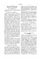
- FIG. 1is an illustration of an artillery shell in which the antenna of the present invention is utilized
- FIG. 2is an illustration of the antenna of the present invention disposed in the nose of a fuse for an artillery shell;
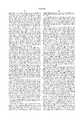
- FIG. 3is a graphical depiction of the radiation pattern of the antenna of the present invention.
- FIG. 4is an illustration of a munitions telemetry system in which the antenna of the present invention may be utilized.
- the artillery shell 100is typically launched or fired from a cannon, mortar, or similar type of gun (not shown).
- a fuse 104is disposed at the nose 102 of shell 100 and is typically physically contiguous with the body of shell 100.
- a fuse, or fuzeis a mechanical or electronic device utilized for detonating an explosive charge such as the charge of an artillery shell or similar munition.
- Shell 100when launched or otherwise projected, travels in a forward direction 106 toward the vicinity of a target.
- the rear 110 of shell 100generally points in the aft direction 112 toward the vicinity of origin of shell 100, i.e. toward the gun from which shell 100 is launched.
- Antenna 128comprises a frustumularly shaped dielectric 116 having a top surface 118 and a bottom surface 120.
- a frustumis generally the part of a solid, such as a cone or pyramid, disposed between two usually parallel cutting planes. More specifically, a frustum is the part of a conical solid left after cutting off the top portion or vertex of the cone with a plane parallel to the base of the cone.
- a frustumis defined also to include any object, form, or shape symmetrically disposed about a longitudinal axis and having an outer surface definable by a line, by a conical section, or by a quadratic equation.
- Antenna 128is disposed in the nose 114 of fuse 126.
- a radiator 122is disposed coincidentally with the central axis of dielectric 116.
- Top surface 118 of dielectric 116is metallized and electrically connected to radiator 122 to function as a capacitance hat for radiator 122.
- bottom surface 120 of dielectric 116is also metallized and functions as a ground plane for radiator 120. Since metallized bottom surface 120 functions as a ground plane, it is not electrically connected to radiator 122.
- antenna 128is a monopole antenna comprising a single radiator 122 having a capacitance hat 118 at the end of radiator 122.
- radiator 122 of antenna 128must be of a length equal to one-quarter of the carrier wavelength for which antenna 128 is designed.
- capacitance hat 118allows the length of radiator 122 to be less than one-quarter of the desired wavelength due to the effects of capacitive loading.
- the shorter length of radiator 122allows the overall size of antenna to be correspondingly smaller as well, thereby facilitating the fit of antenna 128 into the nose 114 of fuse 126.
- Capacitance hat 118(metallized top surface 118 of dielectric 116) is used to implement capacitive loading of monopole radiator 122.
- the length of monopole radiator 122is physically shorter than one-fourth the wavelength of the signal for which antenna 128 is designed.
- Capacitance hat 118is disposed at the end of radiator 122 thereby capacitively loading radiator 122 and effectively tuning antenna 128 to be electrically equivalent to a non-capacitively loaded radiator having a length equal to one-quarter wavelength. Utilization of capacitance hat 118 allows for a shorter physical length of radiator 122 and therefore a reduction in the overall size of antenna 128.
- a reduction in the size of antenna 128allows for antenna 128 to fit within a smaller sized fuse 126 without occupying a large amount of space. Further, capacitive loading of radiator 122 provides an increase in the bandwidth of antenna 128, thereby allowing antenna 128 to be utilized over a greater range of frequencies.
- the bandwidth of antenna 128may also be determined by the diameter of radiator 122. The bandwidth of antenna 128 is proportional to the diameter of radiator 122; the greater the diameter of radiator 122, the greater the bandwidth of antenna 128.
- antenna 128comprises a monolithic structure capable of withstanding the dynamically harsh environment of accelerations greater than or equal to 35,000 g's (where 1 g is the acceleration caused by the earth's gravitational field at seal level) and roll rates greater than or equal to 21,000 rotations per second such as experienced by shell 100 during flight.
- the monopole design of antenna 128is azimuthally symmetric, thereby providing immunity to carrier-phase roll-up and roll-ripple.
- Antenna 128is mechanically robust, low volume, and low cost and does not require power combiners or impedance matching typically required on asymmetrical antenna designs. Consequently, antenna 128 does not suffer the additional power loss of antennas requiring power combiners or impedance matching.
- the impedance of antenna 128is preferably approximately 50 ohms.
- radiator 122determines the center frequency of antenna 128, and the material which dielectric 116 comprises determines the bandwidth of antenna 128.
- Antenna 128is desirably adapted to operate at both L-band and S-band frequencies.
- the overall length of antenna 128is preferably on the order of 0.75 inches or less.
- Antenna 128preferably fits within the envelope of a standard fuse.
- Antenna 128couples to an electronic circuit 132 disposed in fuse 126 via a transmission line 130.
- Transmission line 130preferably comprises a coaxial cable conductor.
- the center conductor of coaxial cable 130electrically connects to radiator 122, and the outer shielding conductor of coaxial cable 130 electrically connects to ground plane 120 of antenna 128.
- the radiation pattern of FIG. 3represents the electric field radiation pattern of antenna 128 of FIG. 2 when transmitting or receiving a signal of a desired wavelength.
- the electric field strength characteristics between 0 degrees to 180 degrees in the positive directioncorresponds to the forward direction 106 of travel of artillery shell 100 as shown in FIG. 1
- the electric field strength characteristics between 0 to 180 degrees in the negative directioncorresponds to the aft direction 112 of artillery shell 100 as shown in FIG. 1.
- antenna 128has a relatively lower gain (greater attenuation) in the forward direction 106, and a relatively greater gain (lower attenuation) in the aft direction 112.
- This type of radiation patternis desirable since communications with a base station located at the point of origin of artillery shell 100 are facilitated, while the susceptibility of antenna 128 to jamming with a signal transmitted from the target location of artillery shell 100 is reduced.
- the desirable radiation pattern of antenna 128 shown in FIG. 3is further enhanced by the conductivity of the casings of fuse 126 and shell 100, whereby the radiation pattern is further "pulled" away from the forward direction 106 toward the aft direction 112. This results from the casings enhancing the effectiveness of ground plane 120.
- An artillery shell (munition) 100is launched toward a target 140, travelling in a forward direction 106 toward target 140.
- a base station 134is located within the vicinity of origin of shell 100 in an aft direction 112 from shell 100 with respect to the forward direction of travel 106 of shell 100.
- Antenna 128facilitates transmission of a radio-frequency telemetry signal 142 between shell 100 and a remote device such as base station 134.
- Base station 134is provided with an antenna 136 for facilitating radio-frequency communications between shell 100 and base station 134.
- antenna 144facilitates reception of a positioning signal 144 received from a space vehicle 138 as part of a constellation of space vehicles in a global positioning system. The positioning signal 144 allows for the instantaneous position and trajectory of shell 100 to be defined and integrated with the telemetry signal 142 such that base station 134 may coordinate the guiding of shell 100 toward target 140 and the detonating of fuse 126.
- Space vehicle 138may be a satellite in the NAVSTAR global positioning system (GPS) maintained and operated by the U.S. government.
- the GPS systemcomprises a constellation of earth orbiting space vehicles that continuously transmit telemetry signals that provide time and position information to a receiver capable of receiving and decoding the telemetry signals.
- electronics 132 of fuse 126may include a GPS receiver such that the instantaneous position and trajectory of munition 100 may be determined.
- electronics 132may include a transmitter or transceiver which relays the GPS time and position information of munition 100 to base station 134 for range correction and auto-registration purposes.
- the signal relayed between artillery shell 100 and base station 134may be a pseudo-lite GPS signal, for example.
Landscapes
- Physics & Mathematics (AREA)
- Engineering & Computer Science (AREA)
- Astronomy & Astrophysics (AREA)
- Aviation & Aerospace Engineering (AREA)
- General Physics & Mathematics (AREA)
- Remote Sensing (AREA)
- Details Of Aerials (AREA)
Abstract
Description
The present invention generally relates to the field of artillery fuses, and particularly to an antenna for utilization in an artillery fuse.
Artillery shells typically utilize a fuse installed at the leading end of the shell. The fuse is a mechanical or electronic device designed to control the detonation of the explosive charge of the shell. Modern artillery fuses further include electronics and telemetry systems for improved accuracy and detonation control. The electronic circuits disposed in the fuse remain in radio-frequency contact with a ground station after launch of the shell for coordinating the trajectory of the shell, making course correction as necessary. Further, the artillery fuse may operate in conjunction with a satellite based positioning system such as the NAVSTAR global positioning system (GPS), maintained and operated by the United States government, for accurately determining the coordinates of the shell as it travels along its trajectory and reaches the point of impact, and for correcting the trajectories of subsequently fired munitions.
An artillery fuse having telemetry and positioning system electronics requires an antenna suitable for the application and environment to which an artillery shell is subject. The fuse antenna should be able to survive the extreme acceleration and high rotational velocities typical of gun launched projectiles. Further, the radiation pattern of the antenna should exhibit relatively high gain in the aft direction, the direction opposite to the direction of travel of the shell. The radiation pattern of the antenna should be minimal in the direction of travel of the shell to minimize or prevent jamming from the vicinity of the target area of the shell. Such an antenna should be of a sufficiently reduced size so as not to occupy a large of space within the interior of the fuse, and is desirably designed for operation with L-band and S-band signals. ("L" is the letter designation for microwave signals in the frequency range from 1 to 2 GHz and "S" is the letter designation for microwave signals in the frequency range from 2-4 GHz.)
The performance of prior antenna configurations such as patch-array designs are subject to performance degradation effects including carrier-phase roll-up and roll-ripple due to antenna asymmetry. It would be desirable to provide an antenna having azimuthal symmetry to avoid such performance degrading problems. It would be further desirable to provide an antenna that does not require power combiners or impedance matching, and that does not suffer impedance loss typical with prior antenna implementations.
The present invention is directed to an antenna for utilization in a fuse of an artillery shell. In one embodiment, the antenna includes a radiator having first and second ends, a length and a diameter for radiating a radio-frequency signal, a capacitance hat disposed at the first end of the radiator for capacitively loading the radiator wherein the capacitance hat is symmetrically disposed with respect to the radiator, and a ground plane disposed at the second end of the radiator wherein the ground plane is symmetrically disposed with respect to the radiator such that the antenna is a monopole antenna. The antenna also includes a dielectric having a top surface, a bottom surface and a central longitudinal axis, the dielectric being symmetrically disposed about the central longitudinal axis wherein radiator is disposed coincidentally with the central longitudinal axis of the dielectric, the capacitance hat is disposed on the top surface of the dielectric and the ground plane is disposed on the bottom surface of the dielectric.
The present invention is also directed to a fuse utilized for detonating the explosive charge of an artillery shell. In one embodiment, the fuse includes a casing symmetrically disposed about a longitudinal central axis and defining an interior cavity, and the antenna of the present invention disposed within the interior cavity of the fuse casing.
It is to be understood that both the foregoing general description and the following detailed description are exemplary and explanatory only and are not restrictive of the invention as claimed.
The accompanying drawings, which are incorporated in and constitute a part of the specification, illustrate an embodiment of the invention and together with the general description, serve to explain the principles of the invention.
The numerous advantages of the present invention may be better understood by those skilled in the art by reference to the accompanying figures in which:
FIG. 1 is an illustration of an artillery shell in which the antenna of the present invention is utilized;
FIG. 2 is an illustration of the antenna of the present invention disposed in the nose of a fuse for an artillery shell;
FIG. 3 is a graphical depiction of the radiation pattern of the antenna of the present invention; and
FIG. 4 is an illustration of a munitions telemetry system in which the antenna of the present invention may be utilized.
Reference will now be made in detail to the presently preferred embodiment of the invention, an example of which is illustrated in the accompanying drawings.
Referring now to FIG. 1, an artillery shell in accordance with the present invention is shown. Theartillery shell 100 is typically launched or fired from a cannon, mortar, or similar type of gun (not shown). A fuse 104 is disposed at the nose 102 ofshell 100 and is typically physically contiguous with the body ofshell 100. A fuse, or fuze, is a mechanical or electronic device utilized for detonating an explosive charge such as the charge of an artillery shell or similar munition. Shell 100, when launched or otherwise projected, travels in aforward direction 106 toward the vicinity of a target. The rear 110 ofshell 100 generally points in theaft direction 112 toward the vicinity of origin ofshell 100, i.e. toward the gun from whichshell 100 is launched.
Referring now to FIG. 2, an artillery shell fuse incorporating the antenna of the present invention is shown. The fuse 126 shown in FIG. 2 is analogous to fuse 104 shown in FIG. 1. Antenna 128 comprises a frustumularly shaped dielectric 116 having a top surface 118 and a bottom surface 120. A frustum is generally the part of a solid, such as a cone or pyramid, disposed between two usually parallel cutting planes. More specifically, a frustum is the part of a conical solid left after cutting off the top portion or vertex of the cone with a plane parallel to the base of the cone. A frustum is defined also to include any object, form, or shape symmetrically disposed about a longitudinal axis and having an outer surface definable by a line, by a conical section, or by a quadratic equation. Antenna 128 is disposed in thenose 114 of fuse 126. A radiator 122 is disposed coincidentally with the central axis of dielectric 116. Top surface 118 of dielectric 116 is metallized and electrically connected to radiator 122 to function as a capacitance hat for radiator 122. Further, bottom surface 120 of dielectric 116 is also metallized and functions as a ground plane for radiator 120. Since metallized bottom surface 120 functions as a ground plane, it is not electrically connected to radiator 122. Metallized bottom surface 120 has an aperture formed therein to allow radiator 122 or a conductor coupled to radiator 122 to pass therethrough. Thus, antenna 128 is a monopole antenna comprising a single radiator 122 having a capacitance hat 118 at the end of radiator 122. Normally, radiator 122 of antenna 128 must be of a length equal to one-quarter of the carrier wavelength for which antenna 128 is designed. However, capacitance hat 118 allows the length of radiator 122 to be less than one-quarter of the desired wavelength due to the effects of capacitive loading. The shorter length of radiator 122 allows the overall size of antenna to be correspondingly smaller as well, thereby facilitating the fit of antenna 128 into thenose 114 of fuse 126.
Capacitance hat 118 (metallized top surface 118 of dielectric 116) is used to implement capacitive loading of monopole radiator 122. The length of monopole radiator 122 is physically shorter than one-fourth the wavelength of the signal for which antenna 128 is designed. Capacitance hat 118 is disposed at the end of radiator 122 thereby capacitively loading radiator 122 and effectively tuning antenna 128 to be electrically equivalent to a non-capacitively loaded radiator having a length equal to one-quarter wavelength. Utilization of capacitance hat 118 allows for a shorter physical length of radiator 122 and therefore a reduction in the overall size of antenna 128. A reduction in the size of antenna 128 allows for antenna 128 to fit within a smaller sized fuse 126 without occupying a large amount of space. Further, capacitive loading of radiator 122 provides an increase in the bandwidth of antenna 128, thereby allowing antenna 128 to be utilized over a greater range of frequencies. The bandwidth of antenna 128 may also be determined by the diameter of radiator 122. The bandwidth of antenna 128 is proportional to the diameter of radiator 122; the greater the diameter of radiator 122, the greater the bandwidth of antenna 128.
In a preferred embodiment of the invention, antenna 128 comprises a monolithic structure capable of withstanding the dynamically harsh environment of accelerations greater than or equal to 35,000 g's (where 1 g is the acceleration caused by the earth's gravitational field at seal level) and roll rates greater than or equal to 21,000 rotations per second such as experienced byshell 100 during flight. The monopole design of antenna 128 is azimuthally symmetric, thereby providing immunity to carrier-phase roll-up and roll-ripple. Antenna 128 is mechanically robust, low volume, and low cost and does not require power combiners or impedance matching typically required on asymmetrical antenna designs. Consequently, antenna 128 does not suffer the additional power loss of antennas requiring power combiners or impedance matching. The impedance of antenna 128 is preferably approximately 50 ohms.
The length and diameter of radiator 122 determines the center frequency of antenna 128, and the material which dielectric 116 comprises determines the bandwidth of antenna 128. Antenna 128 is desirably adapted to operate at both L-band and S-band frequencies. The overall length of antenna 128 is preferably on the order of 0.75 inches or less. Antenna 128 preferably fits within the envelope of a standard fuse.
Antenna 128 couples to an electronic circuit 132 disposed in fuse 126 via a transmission line 130. Transmission line 130 preferably comprises a coaxial cable conductor. The center conductor of coaxial cable 130 electrically connects to radiator 122, and the outer shielding conductor of coaxial cable 130 electrically connects to ground plane 120 of antenna 128.
Referring now to FIG. 3, the radiation pattern of the antenna of the present invention is shown. The radiation pattern of FIG. 3 represents the electric field radiation pattern of antenna 128 of FIG. 2 when transmitting or receiving a signal of a desired wavelength. The electric field strength characteristics between 0 degrees to 180 degrees in the positive direction (upper portion of radiation pattern) corresponds to theforward direction 106 of travel ofartillery shell 100 as shown in FIG. 1, and the electric field strength characteristics between 0 to 180 degrees in the negative direction (lower portion of radiation pattern) corresponds to theaft direction 112 ofartillery shell 100 as shown in FIG. 1. As can be determined from the radiation pattern of FIG, 3, antenna 128 has a relatively lower gain (greater attenuation) in theforward direction 106, and a relatively greater gain (lower attenuation) in theaft direction 112. This type of radiation pattern is desirable since communications with a base station located at the point of origin ofartillery shell 100 are facilitated, while the susceptibility of antenna 128 to jamming with a signal transmitted from the target location ofartillery shell 100 is reduced. The desirable radiation pattern of antenna 128 shown in FIG. 3 is further enhanced by the conductivity of the casings of fuse 126 andshell 100, whereby the radiation pattern is further "pulled" away from theforward direction 106 toward theaft direction 112. This results from the casings enhancing the effectiveness of ground plane 120.
Referring now to FIG. 4, an application of the antenna of the present invention is shown. An artillery shell (munition) 100 is launched toward atarget 140, travelling in aforward direction 106 towardtarget 140. Abase station 134 is located within the vicinity of origin ofshell 100 in anaft direction 112 fromshell 100 with respect to the forward direction oftravel 106 ofshell 100. Antenna 128 facilitates transmission of a radio-frequency telemetry signal 142 betweenshell 100 and a remote device such asbase station 134.Base station 134 is provided with anantenna 136 for facilitating radio-frequency communications betweenshell 100 andbase station 134. Further, antenna 144 facilitates reception of a positioning signal 144 received from aspace vehicle 138 as part of a constellation of space vehicles in a global positioning system. The positioning signal 144 allows for the instantaneous position and trajectory ofshell 100 to be defined and integrated with the telemetry signal 142 such thatbase station 134 may coordinate the guiding ofshell 100 towardtarget 140 and the detonating of fuse 126.
It is believed that the artillery fuse antenna of the present invention and many of its attendant advantages will be understood by the foregoing description, and it will be apparent that various changes may be made in the form, construction and arrangement of the components thereof without departing from the scope and spirit of the invention or without sacrificing all of its material advantages. The form herein before described being merely an explanatory embodiment thereof. It is the intention of the following claims to encompass and include such changes.
Claims (14)
1. An antenna for utilization in a fuse of an artillery shell, comprising:
a radiator having first and second ends, a length and a diameter for radiating a radio-frequency signal;
a capacitance hat disposed at the first end of said radiator for capacitively loading said radiator, said capacitance hat being symmetrically disposed with respect to said radiator; and
a ground plane disposed at the second end of said radiator and being symmetrically disposed with respect to said radiator such that the antenna is a monopole antenna wherein said capacitance hat and said ground plane define a frustum having a central longitudinal axis coincidental with said radiator.
2. An antenna as claimed in claim 1, wherein the said radiator, said capacitance hat and said dielectric are optimized for operation of antenna in the L-band and the S-band.
3. An antenna for utilization in a fuse of an artillery shell, comprising:
a dielectric having a top surface, a bottom surface and a central longitudinal axis, said dielectric being symmetrically disposed about the central longitudinal axis;
a radiator having first and second ends, a length and a diameter for radiating a radio-frequency signal;
a capacitance hat disposed on the top surface of said dielectric and coupled to the first end of said radiator for capacitively loading said radiator;
a ground plane disposed on the bottom surface of said dielectric adjacent to the second end of said radiator such that the antenna is a monopole antenna.
4. An antenna as claimed in claim 3, wherein a said dielectric is frustumularly shaped.
5. An antenna as claimed in claim 3, wherein the top surface of said dielectric is discoidally shaped.
6. An antenna as claimed in claim 3, wherein the bottom surface of said dielectric is discoidally shaped.
7. An antenna as claimed in claim 3, wherein the length and diameter of said radiator and said capacitance hat are optimized for operation of the antenna in the L-band.
8. An antenna as claimed in claim 3, wherein the length and diameter of said radiator and said capacitance hat are optimized for operation of the antenna in the S-band.
9. A fuse utilized for detonating the explosive charge of an artillery shell, comprising:
a casing symmetrically disposed about a longitudinal central axis and defining an interior cavity; and
an antenna for relaying a radio-frequency signal between the fuse and a remote device, said antenna comprising a radiator having first and second ends disposed within the interior cavity coincidentally with the longitudinal central axis, a capacitance hat disposed at the first end of said radiator for capacitively loading said radiator, and a ground plane disposed perpendicular to the longitudinal central axis at the second end of said radiator.
10. A fuse as claimed in claim 9, further comprising a transmitter coupled to said antenna for transmitting a radio-frequency signal from the fuse to the remote device.
11. A fuse as claimed in claim 9, further comprising a receiver coupled to said antenna for receiving a radio-frequency signal from the remote device.
12. A fuse as claimed in claim 9, wherein said antenna is frustumularly shaped.
13. A fuse as claimed in claim 9, wherein said casing increases the effectiveness of said ground plane.
14. A fuse as claimed in claim 9, wherein said antenna is optimized for operation with L-band and S-band signals.
Priority Applications (1)
| Application Number | Priority Date | Filing Date | Title |
|---|---|---|---|
| US09/086,638US6020854A (en) | 1998-05-29 | 1998-05-29 | Artillery fuse antenna for positioning and telemetry |
Applications Claiming Priority (1)
| Application Number | Priority Date | Filing Date | Title |
|---|---|---|---|
| US09/086,638US6020854A (en) | 1998-05-29 | 1998-05-29 | Artillery fuse antenna for positioning and telemetry |
Publications (1)
| Publication Number | Publication Date |
|---|---|
| US6020854Atrue US6020854A (en) | 2000-02-01 |
Family
ID=22199881
Family Applications (1)
| Application Number | Title | Priority Date | Filing Date |
|---|---|---|---|
| US09/086,638Expired - LifetimeUS6020854A (en) | 1998-05-29 | 1998-05-29 | Artillery fuse antenna for positioning and telemetry |
Country Status (1)
| Country | Link |
|---|---|
| US (1) | US6020854A (en) |
Cited By (24)
| Publication number | Priority date | Publication date | Assignee | Title |
|---|---|---|---|---|
| WO2002003497A1 (en)* | 2000-07-05 | 2002-01-10 | Royal Ordnance Plc | Proximity sensing device |
| US6380906B1 (en)* | 2001-04-12 | 2002-04-30 | The United States Of America As Represented By The Secretary Of The Air Force | Airborne and subterranean UHF antenna |
| US20040159261A1 (en)* | 2003-02-18 | 2004-08-19 | Steele Michael F. | Accuracy fuze for airburst cargo delivery projectiles |
| US6834591B2 (en)* | 1998-12-23 | 2004-12-28 | Bae Systems Plc | Proximity fuze |
| US20050078036A1 (en)* | 2001-10-04 | 2005-04-14 | Volker Koch | Projectile comprising a reception antenna for a satellite navigation receiver |
| US20060139225A1 (en)* | 2004-12-28 | 2006-06-29 | Toyota Jidosha Kabushiki Kaisha | Antenna apparatus and communication method employing it |
| US7296520B1 (en)* | 2004-11-15 | 2007-11-20 | United States Of America As Represented By The Secretary | External telemetry unit |
| US7548202B1 (en)* | 2006-08-29 | 2009-06-16 | Rockwell Collins, Inc. | Doppler radio direction finding antenna |
| US20100289687A1 (en)* | 2009-05-15 | 2010-11-18 | Mayflower Communications Company, Inc. | Antijam protected GPS-based measurement of roll rate and roll angle of spinning platforms |
| US8077099B1 (en)* | 2007-06-26 | 2011-12-13 | Rockwell Collins, Inc. | Multi-band symmetric phase center folded monopole antenna for GPS/proximity munitions fuse applications |
| US8138982B1 (en)* | 2007-06-26 | 2012-03-20 | Rockwell Collins, Inc. | Munitions/artillery shell GPS multi-edge slot anti-jamming array |
| US8159403B1 (en)* | 2007-06-26 | 2012-04-17 | Rockwell Collins, Inc. | GPS munitions/artillery anti-jamming array with multi-band capability |
| US8487822B1 (en) | 2007-09-13 | 2013-07-16 | Rockwell Collins, Inc. | Adaptible antenna using liquid metal structures |
| US8723746B1 (en) | 2009-10-01 | 2014-05-13 | Rockwell Collins, Inc. | Slotted ground plane antenna |
| EP2174614B1 (en)* | 2008-10-13 | 2016-05-25 | Covidien LP | Antenna assemblies for medical applications |
| USD773443S1 (en)* | 2014-12-19 | 2016-12-06 | Panasonic Intellectual Property Management Co., Ltd. | Antenna |
| USD775612S1 (en)* | 2014-12-19 | 2017-01-03 | Panasonic Intellectual Property Management Co., Ltd. | Antenna |
| USD951924S1 (en)* | 2020-11-24 | 2022-05-17 | Enrique J Baiz | Vehicle antenna |
| US11555679B1 (en) | 2017-07-07 | 2023-01-17 | Northrop Grumman Systems Corporation | Active spin control |
| US11573069B1 (en) | 2020-07-02 | 2023-02-07 | Northrop Grumman Systems Corporation | Axial flux machine for use with projectiles |
| US11578956B1 (en) | 2017-11-01 | 2023-02-14 | Northrop Grumman Systems Corporation | Detecting body spin on a projectile |
| US12209848B1 (en) | 2017-07-26 | 2025-01-28 | Northrop Grumman Systems Corporation | Despun wing control system for guided projectile maneuvers |
| US12313389B1 (en) | 2022-03-11 | 2025-05-27 | Northrop Grumman Systems Corporation | Tunable safe and arming devices and methods of manufacture |
| US12374800B2 (en) | 2022-03-09 | 2025-07-29 | Hi-Q Military Antennas-AES, LLC | Ruggedized rapid tuning frequency adjustable mobile HF antenna with re-entrant capacitive hat |
Citations (5)
| Publication number | Priority date | Publication date | Assignee | Title |
|---|---|---|---|---|
| US3852756A (en)* | 1974-02-15 | 1974-12-03 | Us Navy | Electrically small resonant antenna with capacitively coupled load |
| US3967276A (en)* | 1975-01-09 | 1976-06-29 | Beam Guidance Inc. | Antenna structures having reactance at free end |
| US4037540A (en)* | 1974-11-16 | 1977-07-26 | Licentia Patent-Verwaltungs-G.M.B.H. | Directional antenna for a projectile or rocket detonator |
| US5652598A (en)* | 1996-02-20 | 1997-07-29 | Trw, Inc. | Charge collector equipped, open-sleeve antennas |
| US5815120A (en)* | 1996-02-28 | 1998-09-29 | International Business Machines Corporation | Radio frequency local area network adapter card structure and method of manufacture |
- 1998
- 1998-05-29USUS09/086,638patent/US6020854A/ennot_activeExpired - Lifetime
Patent Citations (5)
| Publication number | Priority date | Publication date | Assignee | Title |
|---|---|---|---|---|
| US3852756A (en)* | 1974-02-15 | 1974-12-03 | Us Navy | Electrically small resonant antenna with capacitively coupled load |
| US4037540A (en)* | 1974-11-16 | 1977-07-26 | Licentia Patent-Verwaltungs-G.M.B.H. | Directional antenna for a projectile or rocket detonator |
| US3967276A (en)* | 1975-01-09 | 1976-06-29 | Beam Guidance Inc. | Antenna structures having reactance at free end |
| US5652598A (en)* | 1996-02-20 | 1997-07-29 | Trw, Inc. | Charge collector equipped, open-sleeve antennas |
| US5815120A (en)* | 1996-02-28 | 1998-09-29 | International Business Machines Corporation | Radio frequency local area network adapter card structure and method of manufacture |
Cited By (34)
| Publication number | Priority date | Publication date | Assignee | Title |
|---|---|---|---|---|
| US6834591B2 (en)* | 1998-12-23 | 2004-12-28 | Bae Systems Plc | Proximity fuze |
| US20040008035A1 (en)* | 2000-07-05 | 2004-01-15 | Hickey Dennis J. | Proximity sensing device |
| WO2002003497A1 (en)* | 2000-07-05 | 2002-01-10 | Royal Ordnance Plc | Proximity sensing device |
| US6380906B1 (en)* | 2001-04-12 | 2002-04-30 | The United States Of America As Represented By The Secretary Of The Air Force | Airborne and subterranean UHF antenna |
| US7057567B2 (en)* | 2001-10-04 | 2006-06-06 | Diehl Munitionssysteme Gmbh & Co. | Projectile comprising a reception antenna for a satellite navigation receiver |
| US20050078036A1 (en)* | 2001-10-04 | 2005-04-14 | Volker Koch | Projectile comprising a reception antenna for a satellite navigation receiver |
| US20040159261A1 (en)* | 2003-02-18 | 2004-08-19 | Steele Michael F. | Accuracy fuze for airburst cargo delivery projectiles |
| US7121210B2 (en) | 2003-02-18 | 2006-10-17 | Kdi Precision Products, Inc. | Accuracy fuze for airburst cargo delivery projectiles |
| US7296520B1 (en)* | 2004-11-15 | 2007-11-20 | United States Of America As Represented By The Secretary | External telemetry unit |
| US7721648B1 (en)* | 2004-11-15 | 2010-05-25 | United States Of America As Represented By The Secretary | External telemetry method |
| US20060139225A1 (en)* | 2004-12-28 | 2006-06-29 | Toyota Jidosha Kabushiki Kaisha | Antenna apparatus and communication method employing it |
| US7336234B2 (en)* | 2004-12-28 | 2008-02-26 | Toyota Jidosha Kabushiki Kaisha | Antenna apparatus and communication method employing it |
| US7548202B1 (en)* | 2006-08-29 | 2009-06-16 | Rockwell Collins, Inc. | Doppler radio direction finding antenna |
| US8138982B1 (en)* | 2007-06-26 | 2012-03-20 | Rockwell Collins, Inc. | Munitions/artillery shell GPS multi-edge slot anti-jamming array |
| US8077099B1 (en)* | 2007-06-26 | 2011-12-13 | Rockwell Collins, Inc. | Multi-band symmetric phase center folded monopole antenna for GPS/proximity munitions fuse applications |
| US8159403B1 (en)* | 2007-06-26 | 2012-04-17 | Rockwell Collins, Inc. | GPS munitions/artillery anti-jamming array with multi-band capability |
| US8487822B1 (en) | 2007-09-13 | 2013-07-16 | Rockwell Collins, Inc. | Adaptible antenna using liquid metal structures |
| EP2174614B1 (en)* | 2008-10-13 | 2016-05-25 | Covidien LP | Antenna assemblies for medical applications |
| US8106811B2 (en)* | 2009-05-15 | 2012-01-31 | Mayflower Communications Company, Inc. | Antijam protected GPS-based measurement of roll rate and roll angle of spinning platforms |
| US20100289687A1 (en)* | 2009-05-15 | 2010-11-18 | Mayflower Communications Company, Inc. | Antijam protected GPS-based measurement of roll rate and roll angle of spinning platforms |
| US8269667B2 (en) | 2009-05-15 | 2012-09-18 | Mayflower Communications Company, Inc. | GPS-based roll rate and roll angle measurement in the absence of jamming |
| US8723746B1 (en) | 2009-10-01 | 2014-05-13 | Rockwell Collins, Inc. | Slotted ground plane antenna |
| USD773443S1 (en)* | 2014-12-19 | 2016-12-06 | Panasonic Intellectual Property Management Co., Ltd. | Antenna |
| USD775612S1 (en)* | 2014-12-19 | 2017-01-03 | Panasonic Intellectual Property Management Co., Ltd. | Antenna |
| US12158326B1 (en) | 2017-07-07 | 2024-12-03 | Northrop Grumman Systems Corporation | Active spin control |
| US11555679B1 (en) | 2017-07-07 | 2023-01-17 | Northrop Grumman Systems Corporation | Active spin control |
| US12209848B1 (en) | 2017-07-26 | 2025-01-28 | Northrop Grumman Systems Corporation | Despun wing control system for guided projectile maneuvers |
| US11578956B1 (en) | 2017-11-01 | 2023-02-14 | Northrop Grumman Systems Corporation | Detecting body spin on a projectile |
| US12276485B1 (en) | 2017-11-01 | 2025-04-15 | Northrop Grumman Systems Corporation | Detecting body spin on a projectile |
| US11573069B1 (en) | 2020-07-02 | 2023-02-07 | Northrop Grumman Systems Corporation | Axial flux machine for use with projectiles |
| US12055375B2 (en) | 2020-07-02 | 2024-08-06 | Northrop Grumman Systems Corporation | Axial flux machine for use with projectiles |
| USD951924S1 (en)* | 2020-11-24 | 2022-05-17 | Enrique J Baiz | Vehicle antenna |
| US12374800B2 (en) | 2022-03-09 | 2025-07-29 | Hi-Q Military Antennas-AES, LLC | Ruggedized rapid tuning frequency adjustable mobile HF antenna with re-entrant capacitive hat |
| US12313389B1 (en) | 2022-03-11 | 2025-05-27 | Northrop Grumman Systems Corporation | Tunable safe and arming devices and methods of manufacture |
Similar Documents
| Publication | Publication Date | Title |
|---|---|---|
| US6020854A (en) | Artillery fuse antenna for positioning and telemetry | |
| US6098547A (en) | Artillery fuse circumferential slot antenna for positioning and telemetry | |
| US7548202B1 (en) | Doppler radio direction finding antenna | |
| US8138982B1 (en) | Munitions/artillery shell GPS multi-edge slot anti-jamming array | |
| US7570219B1 (en) | Circular polarization antenna for precision guided munitions | |
| US6307514B1 (en) | Method and system for guiding an artillery shell | |
| US5982339A (en) | Antenna system utilizing a frequency selective surface | |
| JP4046565B2 (en) | Interactive satellite terminal antenna system | |
| US8098197B1 (en) | System and method for providing hybrid global positioning system/height of burst antenna operation with optimizied radiation patterns | |
| US4291627A (en) | Electrical fuze with a plurality of modes of operation | |
| US8159403B1 (en) | GPS munitions/artillery anti-jamming array with multi-band capability | |
| CN108370101B (en) | Space station, satellite and associated antenna system | |
| US12107326B2 (en) | Compact antenna system for munition | |
| US8077099B1 (en) | Multi-band symmetric phase center folded monopole antenna for GPS/proximity munitions fuse applications | |
| US4010470A (en) | Multi-function integrated radome-antenna system | |
| GB2272575A (en) | Dual band antenna | |
| US2781512A (en) | Cylindrical notch antenna | |
| US3739386A (en) | Base mounted re-entry vehicle antenna | |
| US3127609A (en) | Antenna having ring waveguide two wavelengths long for feeding two slots in diametrically opposed portions thereof | |
| US4722282A (en) | Payload-carrying projectile | |
| US6919846B2 (en) | Slot antenna for artillery ammunition | |
| KR101457004B1 (en) | Antennas for the Fuze of Projectiles | |
| US7057567B2 (en) | Projectile comprising a reception antenna for a satellite navigation receiver | |
| US6615734B2 (en) | Munition article with antenna for satellite navigation | |
| RU2184343C1 (en) | Radio-controlled anti-aircraft missile |
Legal Events
| Date | Code | Title | Description |
|---|---|---|---|
| AS | Assignment | Owner name:ROCKWELL COLLINS, INC., IOWA Free format text:ASSIGNMENT OF ASSIGNORS INTEREST;ASSIGNORS:JAGNOW, PAUL G.;JENNINGS, WILLIAM C.;REEL/FRAME:009223/0623 Effective date:19980529 | |
| REMI | Maintenance fee reminder mailed | ||
| FPAY | Fee payment | Year of fee payment:4 | |
| SULP | Surcharge for late payment | ||
| REMI | Maintenance fee reminder mailed | ||
| FEPP | Fee payment procedure | Free format text:PETITION RELATED TO MAINTENANCE FEES GRANTED (ORIGINAL EVENT CODE: PMFG); ENTITY STATUS OF PATENT OWNER: LARGE ENTITY Free format text:PETITION RELATED TO MAINTENANCE FEES FILED (ORIGINAL EVENT CODE: PMFP); ENTITY STATUS OF PATENT OWNER: LARGE ENTITY | |
| REIN | Reinstatement after maintenance fee payment confirmed | ||
| PRDP | Patent reinstated due to the acceptance of a late maintenance fee | Effective date:20080313 | |
| FPAY | Fee payment | Year of fee payment:8 | |
| STCF | Information on status: patent grant | Free format text:PATENTED CASE | |
| SULP | Surcharge for late payment | ||
| FP | Lapsed due to failure to pay maintenance fee | Effective date:20080201 | |
| FPAY | Fee payment | Year of fee payment:12 |