US6019791A - Buttress for cardiac valve reconstruction - Google Patents
Buttress for cardiac valve reconstructionDownload PDFInfo
- Publication number
- US6019791A US6019791AUS09/000,059US5998AUS6019791AUS 6019791 AUS6019791 AUS 6019791AUS 5998 AUS5998 AUS 5998AUS 6019791 AUS6019791 AUS 6019791A
- Authority
- US
- United States
- Prior art keywords
- buttress
- fabric
- elongate member
- extended
- longitudinally
- Prior art date
- Legal status (The legal status is an assumption and is not a legal conclusion. Google has not performed a legal analysis and makes no representation as to the accuracy of the status listed.)
- Expired - Lifetime
Links
Images

Classifications
- A—HUMAN NECESSITIES
- A61—MEDICAL OR VETERINARY SCIENCE; HYGIENE
- A61F—FILTERS IMPLANTABLE INTO BLOOD VESSELS; PROSTHESES; DEVICES PROVIDING PATENCY TO, OR PREVENTING COLLAPSING OF, TUBULAR STRUCTURES OF THE BODY, e.g. STENTS; ORTHOPAEDIC, NURSING OR CONTRACEPTIVE DEVICES; FOMENTATION; TREATMENT OR PROTECTION OF EYES OR EARS; BANDAGES, DRESSINGS OR ABSORBENT PADS; FIRST-AID KITS
- A61F2/00—Filters implantable into blood vessels; Prostheses, i.e. artificial substitutes or replacements for parts of the body; Appliances for connecting them with the body; Devices providing patency to, or preventing collapsing of, tubular structures of the body, e.g. stents
- A61F2/02—Prostheses implantable into the body
- A61F2/24—Heart valves ; Vascular valves, e.g. venous valves; Heart implants, e.g. passive devices for improving the function of the native valve or the heart muscle; Transmyocardial revascularisation [TMR] devices; Valves implantable in the body
- A61F2/2442—Annuloplasty rings or inserts for correcting the valve shape; Implants for improving the function of a native heart valve
- A61F2/2445—Annuloplasty rings in direct contact with the valve annulus
- A—HUMAN NECESSITIES
- A61—MEDICAL OR VETERINARY SCIENCE; HYGIENE
- A61F—FILTERS IMPLANTABLE INTO BLOOD VESSELS; PROSTHESES; DEVICES PROVIDING PATENCY TO, OR PREVENTING COLLAPSING OF, TUBULAR STRUCTURES OF THE BODY, e.g. STENTS; ORTHOPAEDIC, NURSING OR CONTRACEPTIVE DEVICES; FOMENTATION; TREATMENT OR PROTECTION OF EYES OR EARS; BANDAGES, DRESSINGS OR ABSORBENT PADS; FIRST-AID KITS
- A61F2/00—Filters implantable into blood vessels; Prostheses, i.e. artificial substitutes or replacements for parts of the body; Appliances for connecting them with the body; Devices providing patency to, or preventing collapsing of, tubular structures of the body, e.g. stents
- A61F2/02—Prostheses implantable into the body
- A61F2/24—Heart valves ; Vascular valves, e.g. venous valves; Heart implants, e.g. passive devices for improving the function of the native valve or the heart muscle; Transmyocardial revascularisation [TMR] devices; Valves implantable in the body
- A61F2/2442—Annuloplasty rings or inserts for correcting the valve shape; Implants for improving the function of a native heart valve
- A61F2/2466—Delivery devices therefor
Definitions
- the present inventionrelates to a buttress for cardiac valve reconstruction of atrioventricular cardiac valves.
- the mitral and tricuspid valvesare located in the left and right atrioventricular openings, respectively, of the heart and serve to prevent regurgitation of blood from the ventricle into the atrium when the ventricle contracts during systole.
- the mitral valvewhich is surrounded by a dense fibrous ring known as the annulus, comprises two valve cusps or leaflets of unequal size, the large or anterior leaflet adjacent the aortic opening and the smaller posterior leaflet.
- the line at which the leaflets come togetheris called the commissure.
- the tricuspid valvecomprises three leaflets, usually referred to as the anterior, posterior and septal cusps, which are attached to a fibrous ring known as the annulus.
- the mitral valveis subjected to significantly higher back pressure than the tricuspid valve. Accordingly, it is more common to require surgery to repair a mitral valve than a tricuspid valve and, therefore, the discussion herein is primarily concerned with mitral valve reconstruction. However, it will be understood that the same principles apply in respect of both mitral and tricuspid valve reconstruction.
- each annulusIn a normal heart, the mitral and tricuspid annuli move in a dynamic and non-planar way with each cardiac cycle.
- the circumference of the mitral and tricuspid annulireduce during systole, so that their respective surface areas reduce by about 20-250%, and then enlarge correspondingly during diastole.
- the movement of each annulus, which is non-planar,is difficult to describe but would be similar to a pitching, yawing, rolling or rotation motion. All the components of each annulus do not necessarily move to the same degree.
- annuloplasty buttresscomprises a rigid annular or part-annular member which is dimensioned to fit against the base of the valve leaflets and is secured in place by sutures.
- Known rigid annular (or closed) annuloplasty ringsaffect the movement of the annulus by preventing normal movement, specifically, by restricting it to planar movement. This reduces ventricular function and, if the ventricle is compromised already, is likely to reduce its efficiency further.
- Another disadvantage of such non-planar movementis a tendancy to force the rigid ring to dehisce or be torn loose from the annulus by the securing sutures being pulled through the tissue. This happens as a result of the stress caused by restraining the annulus from undergoing normal physiological changes during each cardiac cycle.
- the closed nature of a rigid ringprevents the natural change in the circumference of the annulus, in particular, that which occurs during diastole (the relaxation phase of the cardiac cycle) when the surface area of the mitral and tricuspid valve orifices increase by 20-25%.
- the rigid closed ringlimits the movement of the anterior mitral leaflet in the inter-trigonal region. This effectively limits the ability of the closed ring system and, at high flow rates across the mitral or tricuspid valve, is likely to produce obstruction/stenosis.
- a flexible closed ringwas devised for use in atrioventricular annuloplasty.
- the structural properties of the material required for the flexible closed ringare inertness and non-biodegradability.
- the materialshould also permit good, but not excessive, tissue in-growth since excessive tissue in-growth would convert the flexible nature of the device into a rigid device. It was expected that a flexible ring would permit normal movement of the annulus during the cardiac cycle. This should allow the heart to function in a more natural manner and, in addition, should decrease the tendancy of dehiscence because the stress forces in any particular part of the ring would be reduced.
- a subsequent modification of the flexible closed ringinvolved the incorporation of a traction thread which passes through the interior of the ring, with both ends exiting the ring a short distance apart.
- a ringonce implanted, can be reduced in circumferential size, by pulling on the traction thread to contract the ring either symmetrically, by pulling both ends of the traction thread the same amount, or asymmetrically, by pulling one end more than the other. Once the desired ring circumferential size has been achieved, the ends of the traction thread are then tied off.
- a flexible closed ringhas less device-related problems such as haemolysis (red cell damage), or shear damage across the device than a rigid ring. Furthermore, the flexible nature of the flexible closed ring interferes less with ventricular function than the rigid systems described above.
- each of such known closed flexible ringsfail to restore normal heart valve function since, as mentioned above, the most common mitral heart valve defect is a dilation of the posterior two-thirds of the valve annulus and an accompanying loss of the normal shape of the valve. In such circumstances, the natural tendancy of a damaged valve is to re-assume its unnatural shape and one of the disadvantages of known flexible closed rings is that they allow too much movement of the valve annulus, thereby failing to support the damaged annulus sufficiently to restore and maintain a normal annular shape.
- known flexible closed ringsare liable to reduce the orifice area to a greater extent and make it even smaller than the actual ring implanted, due to a "crimping" or buckling effect of sutures as they are tied down, which effectively creates stenosis or obstruction.
- the known flexible closed rings using traction or draw stringssuffer from the same problem as the simple closed flexible rings, in that it is very easy to reduce the orifice size of the mitral ring excessively, thus creating stenosis. In addition, they also leave a cumbersome suture prolapsing, which can specifically be a site for infection and/or haemolysis.
- a buttress for cardiac valve reconstructioncomprising an elongate member formed from a fabric bendable, in use, into an open substantially ring-shaped configuration dimensioned to fit against the base of the cusps of the cardiac valve.
- such a buttress according to the inventionwhich is substantially "C"-shaped, permits both normal non-planar annular movement and expansion/contraction of the annular circumference during the cardiac cycle, whilst, at the same time, restoring the damaged annulus towards its normal physiological shape.
- the arcuate spacing between the free ends of the elongate memberis more than one quarter of the unextended length of the elongate member.
- the buttressis adapted for mitral valve reconstruction and, in use, fits against at least the base of the posterior mitral leaflet.
- the unextended length of the elongate memberapproximates four times the maximum depth of the anterior mitral leaflet, from the base of the anterior leaflet to the commissure with the posterior mitral leaflet.
- the buttressis adapted for tricuspid valve reconstruction and, in use, fits against at least the base of the anterior tricuspid leaflet.
- the fabricis adapted to be both longitudinally and transversely expandable. More advantageously, the fabric is adapted to be longitudinally and transversely expandable by the provision of, on one side, longitudinally extending ribs and, on the reverse side, transversely extending ribs.
- the fabricis woven or knitted from polymerised tetrafluoroethylene.
- the fabricis adapted to be longitudinally extendable to no more than 150%, preferably no more than 125%, more preferably about 105-108% of the length of the elongate member in a non-extended condition.
- the elongate memberis substantially cuboid-shaped.
- the elongate membercomprises two superimposed layers of the fabric, which layers are fastened together by longitudinally extending seams, having inwardly extending, opposing selvedges.
- the elongate membercomprises a length of fabric folded at each end in a reflex manner, to form the two superimposed layers.
- the elongate membercomprises two superimposed lengths of fabric.
- the buttressis impregnated with a radiopaque material comprising an inert, water insoluble, heavy metal compound, preferably barium sulphate or titanium dioxide.
- a radiopaque filamentis provided within the buttress, the radiopaque filament including an inert, water insoluble heavy metal compound such as, for example, barium sulphate or titanium dioxide. This renders the buttress radiopaque and allows it to be observed in vivo radiologically and under fluoroscopy. In addition, from a safety point of view, if the buttress were to migrate, this would allow the buttress to be readily located.
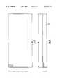
- FIG. 1is a plan view of a fabric column
- FIG. 2is a plan view of a cuff from the fabric column of FIG. 1;
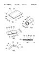
- FIG. 3is a perspective view and FIGS. 4-7 are plan views of sequential steps in a process for the manufacture of a buttress according to a first embodiment of the present invention
- FIGS. 8 and 9are perspective views of steps involved in the manufacture of a buttress according to a second embodiment of the present invention.
- FIG. 10is a perspective view
- FIG. 11is a longitudinal sectional view
- FIG. 12is a plan view of a buttress according to a third embodiment of the present invention.
- FIG. 13is a perspective view of a first embodiment of a holder
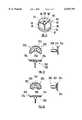
- FIGS. 14A-14Hare plan and end views of sequential steps in assembling a buttress according to the invention onto a second embodiment of a holder;
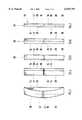
- FIG. 15is underneath, section and side views of a third embodiment of a holder.
- FIG. 16is underneath, section and side views of a fourth embodiment of a holder.
- the buttress 10 according to the inventionis manufactured according to the procedures set out hereinbelow, with reference to the sequential steps illustrated in FIGS. 1-7 of the accompanying drawings.
- the finished buttress 10according to the invention, as illustrated in FIG. 7 of the accompanying drawings, comprises an elongate member 12 which is substantially cuboid-shaped.
- the buttress 10 according to the inventionis formed by longitudinally fastening two layers of fabric 34, 36 together, by means of second and third seams 14, 16 respectively.
- the free ends 22,22' of the fabricare fastened together by a transversely extending first seam 18.
- the buttress 10 according to the inventionmay be rendered radiopaque by either impregnating the fabric with a radiopaque material (not shown) or by providing a radiopaque material (20) in the form of a filament within the lumin of the buttress 10. It will be appreciated that the buttress 10 according to the invention, in itself, is not necessarily radiopaque and it may be desirable to render it radiopaque, in order to be able to observe, in vivo, the movement of the annulus during the cardiac cycle and the location of the buttress 10 within the annulus.
- the buttress 10 according to the present inventionis composed of Teflon MS 010 fabric supplied by Bard of the United Kingdom. Tissue in-growth has been demonstrated to occur reliably when Teflon (Trade Mark) is used in a buttress 10 according to the invention. It will be appreciated that any suitable inert, non-degradable and sufficiently elastic (i.e. expandable and contractable) woven or knitted fabric of medical grade and supportive of tissue in-growth may be used in place of Teflon MS 010. It will also be appreciated that the elastic nature of the fabric may arise because of its mechanical structure and/or its chemical composition. A suitable fabric must, of course, be sufficiently elastic to support the damaged annulus and to permit normal (or almost normal) physiological annular movement during the cardiac cycle.
- the fabricshould be sufficiently elastic to permit longitudinal elongation to no more than 150%, preferably to no more than 125%, most preferably to 105-108% of its unextended length.
- the fabricshould also be transversely extendible, to accommodate non-planar movement of the annulus during the cardiac cycle.
- the fabricshould be sufficiently elastic to permit the 25% increase in atrioventricular valve orifice surface area which occurs during each cardiac cycle.
- woven or knitted fabricsmay be used including fabrics derived from polytetrafluoroethylene (e.g., GoreTex (Trade Mark) and Teflon (Trade Mark)) and from polyethylene terephthalate (e.g., Dacron (Trade Mark)).
- the Teflon fabric sheetis placed on a designated clean work surface, "right side” up, with the ribs running directly away from the operator (ribs partially shown in FIG. 1).
- the operatorcuts parallel with the ribs, to remove any frayed and/or partial ribs from the right hand side of the sheet.
- the operatorthen cuts a column of fabric of width "B", measuring from right to left.
- the appropriate column widthis obtained using, for example, the dimensional information from Table 1 and the relevant measurement is marked with a straight pin. If the measurement falls in the middle of a rib, the pin is moved to the right so that the cut will be made between ribs. A slight cut is made with scissors and the pin is then removed. Cutting is then continued between the ribs from the bottom to the top of the fabric sheet, thereby separating an individual column having the width "B" from the main sheet (see FIG. 1). Further individual columns are then cut by repeating the above steps to yield the desired quantity of fabric columns.
- the column of width "B”is then placed "wrong side” up, and twisted through 90°, so that the ribs are running longways, away from the operator (ribs partially shown in FIG. 2).
- the width of the desired cuffis measured by referring to, for example, the cuff width "C" specified in Table 1, measuring from left to right.
- the desired measurementis marked with a straight pin and a slight cut is made with a scissors.
- the pinis then removed and cutting is continued until an individual cuff has been detached from the column, ensuring at all times that cutting is between the ribs.
- an individual cuff having the dimensions "B" ⁇ "C"is obtained (see FIG. 2).
- the first seam 18is made using an approximately 50 cm length of 5/0 white suture comprising, for example, Filodell coated, virgin braided polyester surgical suture having a diameter of 0.0048 ⁇ 0.001.
- a suitable sutureis supplied by Purcell Sutures of the United Kingdom.
- the 5/0 white sutureis threaded through a size 10B needle, whereupon both thread ends are joined and secured by tying a 1/2 overhand knot (left over right, right over left). The excess thread ends are then trimmed as close to the knot as is possible.
- the threaded needleis then inserted through the right side, making one back stitch (make a stitch, go back over the last stitch one more time), ensuring that the fabric ends are within the stitch.
- the same stitching patternis then continued to the end of the seam, ensuring an even tension along the first seam 18. The operator should avoid pulling the thread too tight as this will cause distortion of the first seam 18.
- the last stitchis placed as for the first stitch, ensuring that the edge of the fabric is taken into the stitch.
- the needleis then passed through the loop and the thread is gently pulled until the loop closes making a loop knot, thereby securing the end.
- the threadis then trimmed as close to the knot as is possible.
- the first seam 18is then opened and flattened with a steel ruler and excess material is trimmed off (not shown).
- the first seam 18is then positioned adjacent the transverse mid-line of the cuff 12 (see FIG. 3).
- An approximately 70 cm length of 5/0 white sutureis threaded through a size 10B needle. Both thread ends are joined and secured by tying a 1/2 overhand knot and the excess thread ends are trimmed as close to the knot as is possible.
- a second seam 14see FIG. 4
- the threaded needleis inserted approximately 3 mm from the respective superimposed selvedges or fabric edges 24,24' and the needle is inserted through the "right side", making one back stitch ensuring that the ends are within the stitch and bringing the needle through the second seam 14 line. Stitching is continued in the same pattern until approximately one third of the second seam 14 is complete.
- the needleis then inserted back into the back stitch already made, making a securing stitch 26 in the second seam 14.
- the normal stitching patternis then continued until approximately two thirds of the second seam 14 has been completed and, again, a securing double back stitch 26 is made.
- the normal stitching patternis then continued to the end of the second seam 14, ensuring an even tension throughout. The operator should avoid pulling the thread too tight as this will cause distortion of the second seam 14.
- the last stitchis placed as for the first stitch, ensuring the edge of the fabric is taken into the stitch.
- the needleis then run back through the final back stitch making a loop in which the needle is passed through.
- the threadis then gently pulled until the loop closes making a loop knot and securing the end.
- the threadis trimmed as close to the knot as is possible.
- a suitable radiopaque material 20comprises radiopaque silicone filaments having a 1.0 ⁇ 0.5 mm diameter, which are obtained from Speciality Silicone Fabricators, Inc.of 3077 Rollie Gates Drive, Paso Robles, Calif. 93446, United States of America under the Trade Name SSF-METN-750.
- a filamenthas a minimum tensile strength of 1200 p.s.i., a minimum elongation of 750% and a minimum tear strength of 200 ppi.
- the silicone filamentis cut into the desired length (see Table 2) using a scissors, a sharp blade or the like, ensuring that an even clean cut is made, which is free from tears, punctures, etc.
- the silicone strip 20is then inserted into the buttress 10 by placing it flat against the second seam 14, ensuring it is not twisted or creased (see FIG. 6 in which the radiopaque strip 20 is illustrated in dotted outline).
- a third seam 16is made using a 70 cm length of 5/0 white suture, which is threaded through a size 10B needle. A 1/2 overhand knot is made and excess thread is trimmed, single suture being used for this seam 16.
- Each of the right hand superimposed selvedges or fabric edges 28,28' of the cuff 12are then folded inwardly to the extent necessary to ensure that the finished buttress 10 conforms to the dimensions specified in Table 2.
- the threaded needleis inserted, to make a back stitch.
- the stitchesare picked up by sewing 1 mm hemming stitch on alternate sides of the seam 16. All stitches are taken in a slightly different area to prevent fatiguing of the fabric. Again, when approximately one third of the third seam 16 is stitched, a securing loop stitch 30 is made.
- the stitching patternis continued, folding both sides 28,28' evenly, until approximately two-thirds of the third seam 16 is complete and, again, a securing loop stitch 30 is made.
- the stitching patternis then continued to the end of the third seam 16 ensuring that the thread is not pulled too tight, so as to cause distortion of the third seam 16.
- the operatorfinishes with a securing loop stitch and the needle is inserted into the corner of the cuff 12.
- the needleis then brought up through the flat of the cuff 12 on the same side as the first seam 18, approximately 10 mm from the edge, ensuring that the needle does not contact the silicone strip 20.
- a 1 mm double back stitchis made, with a loop on the last back stitch to secure the thread.
- the threadis then buried for another 2 mm and excess thread is clipped as close to the fabric as is possible.
- An indicator(visible as 232 in FIG. 12) is attached using a 50 cm length of 5/0 green suture, which is threaded through a size 10B needle.
- the indicatorwhich may be star-shaped, is made on the first seam-less side of the cuff 12 adjacent the transverse mid-line. This is achieved by inserting the needle into the surface of the fabric making a securing back stitch approximately 10 mm from the transverse mid-line. The needle is moved to form a longitudinal stitch and a transverse stitch is then placed through the centre of the longitudinal stitch, thereby forming the "star" shape. The needle is then re-inserted in the surface of the fabric coming up approximately 10 mm on the opposite side of the indicator and a securing back stitch is made.
- the threadis then buried and trimmed as close as is possible to the surface of the fabric.
- the star indicatorserves to flatten the profile of the buttress 10 adjacent the transverse mid-line since, otherwise, the buttress 10 tends to protrude due to the volume displaced by the longitudinal edges 22, 22' of the first seam 18.
- the buttress 10 according to the inventionis sutured into the mitral annulus, with the first seam 18 adjacent the mitral annulus itself, so that the indicator faces the orifice and identifies the transverse mid-line of the buttress 10 according to the invention.
- the buttress 10When the buttress 10 according to the invention is initially formed, the buttress 10 is cuboid and, therefore, extends in a substantially rectilinear direction.
- the trimmed fabric edges 24,24' of the second seam 14 and the fabric edges 28,28' of the third seam 16each extend inwardly, facing each other, within the elongate member 12. These inwardly extending fabric edges 24,24',28,28' provide sufficient structural integrity so that the buttress 10 can, in use, support the damaged annulus so as to restore normal annular function.
- the buttress 10 according to the inventionmay be supplied in a desired arcuate shape, on a holder as described and exemplified in the following Examples 4 and 5.
- the ringmay be shaped to the desired shape by moulding the buttress 10 about a mould of the desired shape (not shown), attaching sutures to the longitudinal ends 38 of the buttress 10 followed by tying the sutures in place so that the desired shape is held. The mould may then be removed.
- sterilisationassists in maintaining the buttress 10 in the desired shape. It has been found that, during sterilisation, moisture is absorbed from the radiopaque material 20 and/or from the surrounding atmosphere--it is believed that this moisture absorption aids in maintaining the desired buttress 10 shape.
- FIGS. 8 and 9illustrate a second embodiment of a buttress 110 according to the present invention, which comprises two superimposed layers 134,136 of fabric for example Teflon felt.
- a suitable feltis manufactured by Meadox Medicals Incorporated of 111 Baurer Drive, Oakland, N.J. 07436, United States of America, under the Trade Mark Meadox.
- the fabrichas been fastened or sewn together by longitudinally extending second and third seams 114,116, following which the elongate member 112 is turned inside out (see FIG.
- the buttress 110is finished off by tucking in the superimposed free ends 122 and by then forming a fourth seam (not shown) at each end 138 thereof.
- FIGS. 10-12 of the accompanying drawingsillustrate a third embodiment of a buttress 210 according to the present invention.
- the buttress 210is formed from one layer of fabric, each longitudinal end 222,222' of which is folded in a reflex manner, to form the required two layers having longitudinal ends 238.
- the layersare then fastened together by longitudinally extending second and third seams 214,216.
- the elongate member 212is then turned inside out (see FIGS. 11 and 12) using a crochet-type hook (not shown) so that the respective fabric edges 224, 224', 228, 228' (fabric edge 228' not visible) of the second and third seams 214,216 now extend inwardly, opposing each other.
- the ends 238 of the elongate member 212are smooth and closed and the buttress 210 is then closed by providing a first seam 218 at a lap joint 40.
- the buttress 210can be shaped to a desired arcuate angle by shaping the buttress 210 about a mould (not shown), by suturing the free ends 238 to each other at the desired spacing (not shown) or in any other manner.
- FIG. 13 of the accompanying drawingsillustrates a first embodiment of a holder generally indicated as 50.
- the holder 50comprises a circumferentially extending rim 52 having a circumferentially extending groove 54, which groove 54 extends over at least a part of the circumference of the rim 52.
- the groove 54is shaped and dimensioned to accept a buttress 10, 110, 210 according to the present invention as will be described in greater detail hereinafter.
- a plurality of radially extending spokes 56support the rim 52.
- Circumferentially arranged apertures 58, 58', 58"are provided in the rim 52.
- FIGS. 14A-H of the accompanying drawingsillustrate a second embodiment of a holder 150.
- the holder 150comprises a circumferentially extending rim 152, supported by radially extending spokes 156.
- a circumferentially extending groove 154is provided to receive a buttress 10, 110, 210 according to the invention.
- the assemblyshould be performed on a designated clean work surface in a clean environment area.
- a suitable holder 150is annular and includes six apertures, A1, A2, A3, B1, B2 and B3, each extending radially through the rim 152.
- the buttress 10, 110, 210 according to the present inventionis assembled on the holder 150 in the following manner.
- a 50 cm length of 2/0 green sutureis threaded through a size 5B needle and a 1/2 overhand knot is made.
- the 2/0 green suturesuitably comprises Filodell coated, virgin braided polyester surgical suture having a diameter of 0.0125 ⁇ 0.001.
- a suitable sutureis supplied by Purcell Sutures of the United Kingdom.
- the buttress 10, 110, 210is positioned in the groove 154, so that, from above, the buttress 10, 110, 210 is not visible and fits snugly in the groove 154.
- the needleis then brought in through A2 and directly through B2 (see FIG. 14B).
- the needleis then brought through the surface fabric of the buttress 10, 110, 210 to the right of B2 (see FIG. 14C) making an approximately 1 mm stitch on the buttress 10, 110, 210.
- the needleis then inserted through B3 and then A3 (see FIG. 14D).
- the needleis then brought up through the middle of one longitudinal end 38 of the buttress 10, 110, 210 on the surface of the fabric making an approximately 1 mm stitch.
- the needleis then placed over the middle of the opposite longitudinal end 38 and again a 1 mm stitch is made on the surface of the fabric (see FIG. 14E).
- the needleis then inserted through A1 and directly through B1 (see FIG. 14F).
- the needleis then brought up through the surface of the fabric making a 1 mm stitch to the left of B2 (see FIG. 14G) and the needle is then brought back through B2 followed through A2 (see FIG. 14H).
- both thread endsWith both thread ends now in the same position, i.e., extending from A2, the thread is then gently pulled an even amount on either side, ensuring that the thread is not pulled too tight as this will cause distortion.
- the operatorshould then ensure that the buttress 10 is secure and firmly in place and four overhand knots are then begun. Upon completion, the thread ends are cut as close to the knot as is possible.
- an identification tag(not shown) may be attached to the buttress 10, 110, 210.
- Such an identification tagmay carry a serial number.
- the identification tagmay be attached using an approximately 50 cm length of 5/0 white suture threaded into a size 10B needle.
- the assembled buttress 10, 110, 210 according to the invention and holder 150may then be placed in a pouch which can be heat sealed.
- the buttress/holderWhen it is desired to perform annuloplasty using a buttress according to the present invention, the buttress/holder is removed from the pouch and offered to the annulus where the buttress is sutured into place. When the buttress is secured to the annulus, the green suture connecting the buttress to the holder is severed and the green suture and the holder are discarded. Since the buttress has been offered to the posterior aspect of the annulus extended beyond its unextended length, this urges the posterior aspect to contract, thereby restoring the normal resting orifice surface area.
- the buttressmay be offered to the orifice without a holder.
- FIGS. 15 and 16 of the accompanying drawingsillustrate alternative holders 250, 350.
- FIG. 15illustrates plan, side and sectional views of a pen-torus-shaped holder 250 having a scalloped flange 262 extending from the rim 252 of the pen-torus.
- FIG. 16illustrates plan, side and sectional views of a pen-toroid-shaped holder 350, having a scalloped flange 362 extending from the rim 352 of the pen-toroid.
- Assembly of a buttress 10, 110, 210 according to the present invention on each of these holders 250, 350involves stitching the buttress 10, 110, 210 onto the holder 250, 350 by threading the needle through the apertures indicated in dotted outline on the respective sectional views.
- the buttress 10, 110, 210is desirably elongated on the holder 250, 350 by gently pulling the suture threads evenly, before securely tying them.
- the overall 30 day hospital mortalitywas 8 of 261 patients (3%), whereas the 30 day hospital mortality for isolated mitral annuloplasty was 1 of 152 patients (0.65%).
- the actuarial 1 year, 5 year and 10 year survival rateswere 96%, 93% and 90%, respectively.
- the re-operation free rates at 5 years and 10 yearswere 92% and 90%, respectively.
- the rigid closed ring Carpentier group of patientsactuarially had an incidence of repair failure of three cases at a mean follow-up of one year.
- the mean follow-up for the 77 patients receiving a buttress according to the present inventionis thirteen months, with two patients requiring re-operation for reconstruction failure.
- the ex-planted flexible buttress devicesshowed no technical fault, which compares most favourably with the rigid ring population.
- mitral reconstruction by annuloplasty using a buttress 10, 110, 210 according to the present inventionis a stable durable repair with low mortality and low re-operation rates. Furthermore, correct positioning in the annulus and correct elongation of the buttress 10, 110, 210 according to the present invention, is facilitated by using a holder 50, 150, 250, 350.
Landscapes
- Health & Medical Sciences (AREA)
- Cardiology (AREA)
- Oral & Maxillofacial Surgery (AREA)
- Transplantation (AREA)
- Engineering & Computer Science (AREA)
- Biomedical Technology (AREA)
- Heart & Thoracic Surgery (AREA)
- Vascular Medicine (AREA)
- Life Sciences & Earth Sciences (AREA)
- Animal Behavior & Ethology (AREA)
- General Health & Medical Sciences (AREA)
- Public Health (AREA)
- Veterinary Medicine (AREA)
- Prostheses (AREA)
- Check Valves (AREA)
- External Artificial Organs (AREA)
Abstract
Description
TABLE 1 ______________________________________ Buttress Size, Fabric Column and Cuff Dimensions Buttress Fabric Column Cuff Fabric Dimension Size Width Length "A" "B" (mm) "C" (mm) ______________________________________ R30 128 10 R32 10 R34 10 R36 10 R38 10 R40 10 ______________________________________
TABLE 2 ______________________________________ Length of Radiopaque Material and Dimensions of Finished Buttress according to the invention Radiopaque Finished Finished Buttress Silicone Buttress Buttress Size Length "D" Width "E" Length "F" "A" (mm) (mm) (mm) ______________________________________R30 56 4.5 60 R32 60 4.5 64 R34 64 4.5 68 R36 68 4.5 72 R38 72 4.5 76 R40 76 4.5 80 ______________________________________
Claims (28)
Applications Claiming Priority (3)
| Application Number | Priority Date | Filing Date | Title |
|---|---|---|---|
| IE950546 | 1995-07-17 | ||
| IE950546 | 1995-07-17 | ||
| PCT/IE1996/000041WO1997003625A1 (en) | 1995-07-17 | 1996-07-17 | A buttress for cardiac valve reconstruction |
Publications (1)
| Publication Number | Publication Date |
|---|---|
| US6019791Atrue US6019791A (en) | 2000-02-01 |
Family
ID=11040827
Family Applications (1)
| Application Number | Title | Priority Date | Filing Date |
|---|---|---|---|
| US09/000,059Expired - LifetimeUS6019791A (en) | 1995-07-17 | 1996-07-17 | Buttress for cardiac valve reconstruction |
Country Status (12)
| Country | Link |
|---|---|
| US (1) | US6019791A (en) |
| EP (1) | EP0840579B1 (en) |
| JP (1) | JPH11509126A (en) |
| CN (1) | CN1150865C (en) |
| AT (1) | ATE254892T1 (en) |
| AU (1) | AU720447C (en) |
| BR (1) | BR9609768A (en) |
| CA (1) | CA2227142A1 (en) |
| DE (1) | DE69630888T2 (en) |
| ES (1) | ES2211966T3 (en) |
| IE (1) | IES71161B2 (en) |
| WO (1) | WO1997003625A1 (en) |
Cited By (144)
| Publication number | Priority date | Publication date | Assignee | Title |
|---|---|---|---|---|
| US6726716B2 (en) | 2001-08-24 | 2004-04-27 | Edwards Lifesciences Corporation | Self-molding annuloplasty ring |
| EP1294310A4 (en)* | 2000-05-22 | 2004-07-07 | Shlomo Gabbay | Cardiac prosthesis for helping improve operation of a heart valve |
| US20060085030A1 (en)* | 2004-10-15 | 2006-04-20 | Bettuchi Michael J | Seal element for anastomosis |
| US20060085034A1 (en)* | 2004-10-18 | 2006-04-20 | Bettuchi Michael J | Support structures and methods of using the same |
| US20060135992A1 (en)* | 2004-10-18 | 2006-06-22 | Bettuchi Michael J | Annular adhesive structure |
| US20070179528A1 (en)* | 2006-02-02 | 2007-08-02 | Soltz Michael A | Mechanically tuned buttress material to assist with proper formation of surgical element in diseased tissue |
| US20070203510A1 (en)* | 2006-02-28 | 2007-08-30 | Bettuchi Michael J | Annular disk for reduction of anastomotic tension and methods of using the same |
| US20080110959A1 (en)* | 2002-06-17 | 2008-05-15 | Tyco Healthcare Group Lp | Annular support structures |
| US20080140115A1 (en)* | 2004-08-17 | 2008-06-12 | Stopek Joshua B | Stapling Support Structures |
| US20080303045A1 (en)* | 2007-04-09 | 2008-12-11 | Rohm Co., Ltd. | Semiconductor light emitting device |
| US20080308608A1 (en)* | 2007-06-18 | 2008-12-18 | Prommersberger Megan L | Interlocking buttress material retention system |
| US20080314960A1 (en)* | 2007-06-22 | 2008-12-25 | Stanislaw Marczyk | Detachable buttress material retention systems for use with a surgical stapling device |
| US20090001122A1 (en)* | 2007-06-27 | 2009-01-01 | Megan Prommersberger | Buttress and surgical stapling apparatus |
| US20090095792A1 (en)* | 2006-02-28 | 2009-04-16 | Bettuchi Michael J | Hub for positioning annular structure on a surgical device |
| US20090134200A1 (en)* | 2007-03-06 | 2009-05-28 | Danyel Tarinelli | Surgical stapling apparatus |
| US20090218384A1 (en)* | 2007-06-18 | 2009-09-03 | Ernie Aranyi | Structure for attachment of buttress material to anvils and cartridges of surgical staplers |
| US20090287230A1 (en)* | 2005-03-15 | 2009-11-19 | Tyco Healthcare Group Lp | Anastomosis composite gasket |
| US20100016888A1 (en)* | 2005-05-05 | 2010-01-21 | Allison Calabrese | Surgical Gasket |
| US20100012703A1 (en)* | 2005-05-05 | 2010-01-21 | Allison Calabrese | Surgical Gasket |
| US20100012704A1 (en)* | 2007-03-06 | 2010-01-21 | Danyel Tarinelli Racenet | Surgical Stapling Apparatus |
| US20100065606A1 (en)* | 2006-10-26 | 2010-03-18 | Stopek Megan L | Methods of Using Shape Memory Alloys for Buttress Attachment |
| US20100147922A1 (en)* | 2008-12-16 | 2010-06-17 | Tyco Healthcare Group Lp | Surgical Apparatus Including Surgical Buttress |
| US20100147923A1 (en)* | 2005-03-15 | 2010-06-17 | Tyco Healthcare Group Lp | Circular anastomosis structures |
| US20100243707A1 (en)* | 2009-03-31 | 2010-09-30 | Lee Olson | Surgical stapling apparatus |
| US20100243708A1 (en)* | 2009-03-31 | 2010-09-30 | Ernie Aranyi | Surgical stapling apparatus |
| US20100249805A1 (en)* | 2009-03-31 | 2010-09-30 | Lee Olson | Crimp And Release Of Suture Holding Buttress Material |
| US7845536B2 (en) | 2004-10-18 | 2010-12-07 | Tyco Healthcare Group Lp | Annular adhesive structure |
| US20110101070A1 (en)* | 2007-05-25 | 2011-05-05 | Tyco Healthcare Group Lp | Staple buttress retention system |
| US7967179B2 (en) | 2009-03-31 | 2011-06-28 | Tyco Healthcare Group Lp | Center cinch and release of buttress material |
| US8157151B2 (en) | 2009-10-15 | 2012-04-17 | Tyco Healthcare Group Lp | Staple line reinforcement for anvil and cartridge |
| US8348130B2 (en) | 2010-12-10 | 2013-01-08 | Covidien Lp | Surgical apparatus including surgical buttress |
| US8348126B2 (en) | 2009-03-31 | 2013-01-08 | Covidien Lp | Crimp and release of suture holding buttress material |
| US8365972B2 (en) | 2009-03-31 | 2013-02-05 | Covidien Lp | Surgical stapling apparatus |
| US8479968B2 (en) | 2011-03-10 | 2013-07-09 | Covidien Lp | Surgical instrument buttress attachment |
| US8584920B2 (en) | 2011-11-04 | 2013-11-19 | Covidien Lp | Surgical stapling apparatus including releasable buttress |
| US8789737B2 (en) | 2011-04-27 | 2014-07-29 | Covidien Lp | Circular stapler and staple line reinforcement material |
| US8814025B2 (en) | 2011-09-15 | 2014-08-26 | Ethicon Endo-Surgery, Inc. | Fibrin pad matrix with suspended heat activated beads of adhesive |
| US8820606B2 (en) | 2012-02-24 | 2014-09-02 | Covidien Lp | Buttress retention system for linear endostaplers |
| US8899464B2 (en) | 2011-10-03 | 2014-12-02 | Ethicon Endo-Surgery, Inc. | Attachment of surgical staple buttress to cartridge |
| US8956406B2 (en) | 2008-04-16 | 2015-02-17 | Heart Repair Technologies, Inc. | Transvalvular intraanular band and chordae cutting for ischemic and dilated cardiomyopathy |
| US8961597B2 (en) | 2008-04-16 | 2015-02-24 | Heart Repair Technologies, Inc. | Percutaneous transvalvular intraannular band for mitral valve repair |
| US8967448B2 (en) | 2011-12-14 | 2015-03-03 | Covidien Lp | Surgical stapling apparatus including buttress attachment via tabs |
| US8985429B2 (en) | 2011-09-23 | 2015-03-24 | Ethicon Endo-Surgery, Inc. | Surgical stapling device with adjunct material application feature |
| US8998059B2 (en) | 2011-08-01 | 2015-04-07 | Ethicon Endo-Surgery, Inc. | Adjunct therapy device having driver with cavity for hemostatic agent |
| US8998060B2 (en) | 2011-09-13 | 2015-04-07 | Ethicon Endo-Surgery, Inc. | Resistive heated surgical staple cartridge with phase change sealant |
| US9010609B2 (en) | 2012-01-26 | 2015-04-21 | Covidien Lp | Circular stapler including buttress |
| US9010612B2 (en) | 2012-01-26 | 2015-04-21 | Covidien Lp | Buttress support design for EEA anvil |
| US9010608B2 (en) | 2011-12-14 | 2015-04-21 | Covidien Lp | Releasable buttress retention on a surgical stapler |
| US9084602B2 (en) | 2011-01-26 | 2015-07-21 | Covidien Lp | Buttress film with hemostatic action for surgical stapling apparatus |
| US9089326B2 (en) | 2011-10-07 | 2015-07-28 | Ethicon Endo-Surgery, Inc. | Dual staple cartridge for surgical stapler |
| US9101359B2 (en) | 2011-09-13 | 2015-08-11 | Ethicon Endo-Surgery, Inc. | Surgical staple cartridge with self-dispensing staple buttress |
| US9113885B2 (en) | 2011-12-14 | 2015-08-25 | Covidien Lp | Buttress assembly for use with surgical stapling device |
| US9125649B2 (en) | 2011-09-15 | 2015-09-08 | Ethicon Endo-Surgery, Inc. | Surgical instrument with filled staple |
| US9161753B2 (en) | 2012-10-10 | 2015-10-20 | Covidien Lp | Buttress fixation for a circular stapler |
| US9168137B2 (en) | 2008-04-16 | 2015-10-27 | Heart Repair Technologies, Inc. | Transvalvular intraannular band for aortic valve repair |
| US9192383B2 (en) | 2013-02-04 | 2015-11-24 | Covidien Lp | Circular stapling device including buttress material |
| US9192384B2 (en) | 2012-11-09 | 2015-11-24 | Covidien Lp | Recessed groove for better suture retention |
| US9198644B2 (en) | 2011-09-22 | 2015-12-01 | Ethicon Endo-Surgery, Inc. | Anvil cartridge for surgical fastening device |
| US9204881B2 (en) | 2013-01-11 | 2015-12-08 | Covidien Lp | Buttress retainer for EEA anvil |
| US9237892B2 (en) | 2011-12-14 | 2016-01-19 | Covidien Lp | Buttress attachment to the cartridge surface |
| US9254180B2 (en) | 2011-09-15 | 2016-02-09 | Ethicon Endo-Surgery, Inc. | Surgical instrument with staple reinforcement clip |
| US9295466B2 (en) | 2012-11-30 | 2016-03-29 | Covidien Lp | Surgical apparatus including surgical buttress |
| US9326773B2 (en) | 2012-01-26 | 2016-05-03 | Covidien Lp | Surgical device including buttress material |
| US9351731B2 (en) | 2011-12-14 | 2016-05-31 | Covidien Lp | Surgical stapling apparatus including releasable surgical buttress |
| US9351732B2 (en) | 2011-12-14 | 2016-05-31 | Covidien Lp | Buttress attachment to degradable polymer zones |
| US9393018B2 (en) | 2011-09-22 | 2016-07-19 | Ethicon Endo-Surgery, Inc. | Surgical staple assembly with hemostatic feature |
| US9402627B2 (en) | 2012-12-13 | 2016-08-02 | Covidien Lp | Folded buttress for use with a surgical apparatus |
| US9414839B2 (en) | 2013-02-04 | 2016-08-16 | Covidien Lp | Buttress attachment for circular stapling device |
| US9433420B2 (en) | 2013-01-23 | 2016-09-06 | Covidien Lp | Surgical apparatus including surgical buttress |
| US9486215B2 (en) | 2009-03-31 | 2016-11-08 | Covidien Lp | Surgical stapling apparatus |
| US9492170B2 (en) | 2011-08-10 | 2016-11-15 | Ethicon Endo-Surgery, Inc. | Device for applying adjunct in endoscopic procedure |
| US9504470B2 (en) | 2013-02-25 | 2016-11-29 | Covidien Lp | Circular stapling device with buttress |
| US9522002B2 (en) | 2012-12-13 | 2016-12-20 | Covidien Lp | Surgical instrument with pressure distribution device |
| US9572576B2 (en) | 2012-07-18 | 2017-02-21 | Covidien Lp | Surgical apparatus including surgical buttress |
| US9610080B2 (en) | 2009-10-15 | 2017-04-04 | Covidien Lp | Staple line reinforcement for anvil and cartridge |
| US20170119390A1 (en)* | 2015-10-29 | 2017-05-04 | Ethicon Endo-Surgery, Llc | Surgical stapler buttress assembly with features to interact with movable end effector components |
| US9655620B2 (en) | 2013-10-28 | 2017-05-23 | Covidien Lp | Circular surgical stapling device including buttress material |
| US9675351B2 (en) | 2011-10-26 | 2017-06-13 | Covidien Lp | Buttress release from surgical stapler by knife pushing |
| US9681936B2 (en) | 2012-11-30 | 2017-06-20 | Covidien Lp | Multi-layer porous film material |
| US9693772B2 (en) | 2009-10-15 | 2017-07-04 | Covidien Lp | Staple line reinforcement for anvil and cartridge |
| US9782173B2 (en) | 2013-03-07 | 2017-10-10 | Covidien Lp | Circular stapling device including buttress release mechanism |
| US9844378B2 (en) | 2014-04-29 | 2017-12-19 | Covidien Lp | Surgical stapling apparatus and methods of adhering a surgical buttress thereto |
| US9931116B2 (en) | 2012-02-10 | 2018-04-03 | Covidien Lp | Buttress composition |
| US9999408B2 (en) | 2011-09-14 | 2018-06-19 | Ethicon Endo-Surgery, Inc. | Surgical instrument with fluid fillable buttress |
| US10293553B2 (en) | 2009-10-15 | 2019-05-21 | Covidien Lp | Buttress brachytherapy and integrated staple line markers for margin identification |
| US10368868B2 (en) | 2017-03-09 | 2019-08-06 | Covidien Lp | Structure for attaching buttress material to anvil and cartridge of surgical stapling instrument |
| US10420556B2 (en) | 2012-11-09 | 2019-09-24 | Covidien Lp | Surgical stapling apparatus including buttress attachment |
| US10456259B2 (en) | 2008-04-16 | 2019-10-29 | Heart Repair Technologies, Inc. | Transvalvular intraannular band for mitral valve repair |
| US10470767B2 (en) | 2015-02-10 | 2019-11-12 | Covidien Lp | Surgical stapling instrument having ultrasonic energy delivery |
| US10576298B2 (en) | 2009-10-15 | 2020-03-03 | Covidien Lp | Buttress brachytherapy and integrated staple line markers for margin identification |
| US10722234B2 (en) | 2013-02-28 | 2020-07-28 | Covidien Lp | Adherence concepts for non-woven absorbable felt buttresses |
| US10758237B2 (en) | 2018-04-30 | 2020-09-01 | Covidien Lp | Circular stapling apparatus with pinned buttress |
| US20200318261A1 (en)* | 2017-12-15 | 2020-10-08 | Toray Industries, Inc. | Woven fabric and method for manufacturing same |
| US10806459B2 (en) | 2018-09-14 | 2020-10-20 | Covidien Lp | Drug patterned reinforcement material for circular anastomosis |
| US10835216B2 (en) | 2014-12-24 | 2020-11-17 | Covidien Lp | Spinneret for manufacture of melt blown nonwoven fabric |
| US10842485B2 (en) | 2009-10-15 | 2020-11-24 | Covidien Lp | Brachytherapy buttress |
| US10849625B2 (en) | 2017-08-07 | 2020-12-01 | Covidien Lp | Surgical buttress retention systems for surgical stapling apparatus |
| US10874768B2 (en) | 2017-01-20 | 2020-12-29 | Covidien Lp | Drug eluting medical device |
| US10881395B2 (en) | 2012-08-20 | 2021-01-05 | Covidien Lp | Buttress attachment features for surgical stapling apparatus |
| US10925607B2 (en) | 2017-02-28 | 2021-02-23 | Covidien Lp | Surgical stapling apparatus with staple sheath |
| US10945733B2 (en) | 2017-08-23 | 2021-03-16 | Covidien Lp | Surgical buttress reload and tip attachment assemblies for surgical stapling apparatus |
| US10952729B2 (en) | 2018-10-03 | 2021-03-23 | Covidien Lp | Universal linear buttress retention/release assemblies and methods |
| US10959731B2 (en) | 2016-06-14 | 2021-03-30 | Covidien Lp | Buttress attachment for surgical stapling instrument |
| US11013599B2 (en) | 2008-04-16 | 2021-05-25 | Heart Repair Technologies, Inc. | Percutaneous transvalvular intraannular band for mitral valve repair |
| US11020578B2 (en) | 2015-04-10 | 2021-06-01 | Covidien Lp | Surgical stapler with integrated bladder |
| US11026686B2 (en) | 2016-11-08 | 2021-06-08 | Covidien Lp | Structure for attaching buttress to anvil and/or cartridge of surgical stapling instrument |
| US11033391B2 (en) | 2016-12-22 | 2021-06-15 | Heart Repair Technologies, Inc. | Percutaneous delivery systems for anchoring an implant in a cardiac valve annulus |
| US11065000B2 (en) | 2018-02-22 | 2021-07-20 | Covidien Lp | Surgical buttresses for surgical stapling apparatus |
| US11083579B2 (en) | 2008-04-16 | 2021-08-10 | Heart Repair Technologies, Inc. | Transvalvular intraanular band and chordae cutting for ischemic and dilated cardiomyopathy |
| US11096610B2 (en) | 2017-03-28 | 2021-08-24 | Covidien Lp | Surgical implants including sensing fibers |
| US11141151B2 (en) | 2017-12-08 | 2021-10-12 | Covidien Lp | Surgical buttress for circular stapling |
| US11219460B2 (en) | 2018-07-02 | 2022-01-11 | Covidien Lp | Surgical stapling apparatus with anvil buttress |
| US20220079584A1 (en)* | 2020-09-16 | 2022-03-17 | Ethicon Llc | Apparatus and method to apply buttress to end effector of surgical stapler with authentication |
| US11284896B2 (en) | 2018-05-09 | 2022-03-29 | Covidien Lp | Surgical buttress loading and attaching/detaching assemblies |
| US11337699B2 (en) | 2020-04-28 | 2022-05-24 | Covidien Lp | Magnesium infused surgical buttress for surgical stapler |
| US11399833B2 (en) | 2020-10-19 | 2022-08-02 | Covidien Lp | Anvil buttress attachment for surgical stapling apparatus |
| US11419605B2 (en) | 2020-09-16 | 2022-08-23 | Cilag Gmbh International | Apparatus and method to close end effector of surgical stapler onto buttress |
| US11426163B2 (en) | 2018-05-09 | 2022-08-30 | Covidien Lp | Universal linear surgical stapling buttress |
| US11432818B2 (en) | 2018-05-09 | 2022-09-06 | Covidien Lp | Surgical buttress assemblies |
| US11452523B2 (en) | 2020-09-16 | 2022-09-27 | Cilag Gmbh International | Apparatus and method to apply buttresses separately to jaws of end effector of surgical stapler |
| US11478245B2 (en) | 2019-05-08 | 2022-10-25 | Covidien Lp | Surgical stapling device |
| US11510670B1 (en) | 2021-06-23 | 2022-11-29 | Covidien Lp | Buttress attachment for surgical stapling apparatus |
| US11523824B2 (en) | 2019-12-12 | 2022-12-13 | Covidien Lp | Anvil buttress loading for a surgical stapling apparatus |
| US11534170B2 (en) | 2021-01-04 | 2022-12-27 | Covidien Lp | Anvil buttress attachment for surgical stapling apparatus |
| US11547407B2 (en) | 2020-03-19 | 2023-01-10 | Covidien Lp | Staple line reinforcement for surgical stapling apparatus |
| US11559306B2 (en) | 2020-09-16 | 2023-01-24 | Cilag Gmbh International | Apparatus and method to detect full seating of buttress applicator in end effector of surgical stapler |
| US11564683B2 (en) | 2020-09-16 | 2023-01-31 | Cilag Gmbh International | Apparatus and method to apply buttress to end effector of surgical stapler via driven member |
| US11571208B2 (en) | 2019-10-11 | 2023-02-07 | Covidien Lp | Surgical buttress loading units |
| US11596399B2 (en) | 2021-06-23 | 2023-03-07 | Covidien Lp | Anvil buttress attachment for surgical stapling apparatus |
| US11596403B2 (en) | 2019-05-08 | 2023-03-07 | Covidien Lp | Surgical stapling device |
| US11660093B2 (en) | 2020-09-16 | 2023-05-30 | Cilag Gmbh International | Method of applying buttress to end effector of surgical stapler |
| US11672538B2 (en) | 2021-06-24 | 2023-06-13 | Covidien Lp | Surgical stapling device including a buttress retention assembly |
| US11678879B2 (en) | 2021-07-01 | 2023-06-20 | Covidien Lp | Buttress attachment for surgical stapling apparatus |
| US11684368B2 (en) | 2021-07-14 | 2023-06-27 | Covidien Lp | Surgical stapling device including a buttress retention assembly |
| US11707276B2 (en) | 2020-09-08 | 2023-07-25 | Covidien Lp | Surgical buttress assemblies and techniques for surgical stapling |
| US11730472B2 (en) | 2019-04-25 | 2023-08-22 | Covidien Lp | Surgical system and surgical loading units thereof |
| US11751875B2 (en) | 2021-10-13 | 2023-09-12 | Coviden Lp | Surgical buttress attachment assemblies for surgical stapling apparatus |
| US11766261B2 (en) | 2020-09-16 | 2023-09-26 | Cilag Gmbh International | Apparatus and method to apply buttress to end effector of surgical stapler via fixed base |
| US11801052B2 (en) | 2021-08-30 | 2023-10-31 | Covidien Lp | Assemblies for surgical stapling instruments |
| US11806017B2 (en) | 2021-11-23 | 2023-11-07 | Covidien Lp | Anvil buttress loading system for surgical stapling apparatus |
| US11969169B2 (en) | 2019-09-10 | 2024-04-30 | Covidien Lp | Anvil buttress loading unit for a surgical stapling apparatus |
| US12070213B2 (en) | 2022-02-24 | 2024-08-27 | Covidien Lp | Surgical medical devices |
| US12076013B2 (en) | 2021-08-03 | 2024-09-03 | Covidien Lp | Surgical buttress attachment assemblies for surgical stapling apparatus |
| US12364604B2 (en) | 2019-02-11 | 2025-07-22 | Heart Repair Technologies, Inc. | Percutaneous delivery systems for anchoring an implant in a cardiac valve annulus |
Families Citing this family (6)
| Publication number | Priority date | Publication date | Assignee | Title |
|---|---|---|---|---|
| AU8882298A (en) | 1997-08-28 | 1999-03-22 | Alfred Edward Wood | Apparatus for selecting a suitably dimensioned buttress for a mitral valve |
| EP1432369B1 (en) | 2001-08-31 | 2008-02-27 | Mitral Interventions | Apparatus for valve repair |
| US7101395B2 (en) | 2002-06-12 | 2006-09-05 | Mitral Interventions, Inc. | Method and apparatus for tissue connection |
| CA2813136A1 (en)* | 2004-02-27 | 2005-09-15 | Aortx, Inc. | Prosthetic heart valve delivery systems and methods |
| CN102247225B (en)* | 2005-02-28 | 2015-07-22 | 梅德坦提亚国际有限公司 | Device for improving the function of heart valve and kit |
| US7739971B2 (en)* | 2005-06-07 | 2010-06-22 | Edwards Lifesciences Corporation | Systems and methods for assembling components of a fabric-covered prosthetic heart valve |
Citations (8)
| Publication number | Priority date | Publication date | Assignee | Title |
|---|---|---|---|---|
| US4042979A (en)* | 1976-07-12 | 1977-08-23 | Angell William W | Valvuloplasty ring and prosthetic method |
| US4055861A (en)* | 1975-04-11 | 1977-11-01 | Rhone-Poulenc Industries | Support for a natural human heart valve |
| US4164046A (en)* | 1977-05-16 | 1979-08-14 | Cooley Denton | Valve prosthesis |
| EP0338994A1 (en)* | 1988-01-12 | 1989-10-25 | Mario Morea | Prosthetic device for the surgical correction of tricuspid insufficiency |
| WO1993015690A2 (en)* | 1992-01-27 | 1993-08-19 | Medtronic, Inc. | Annuloplasty and suture rings |
| US5290300A (en)* | 1989-07-31 | 1994-03-01 | Baxter International Inc. | Flexible suture guide and holder |
| US5397348A (en)* | 1993-12-13 | 1995-03-14 | Carbomedics, Inc. | Mechanical heart valve with compressible stiffening ring |
| US5522884A (en)* | 1993-02-19 | 1996-06-04 | Medtronic, Inc. | Holder for adjustable mitral & tricuspid annuloplasty rings |
- 1996
- 1996-07-17CACA002227142Apatent/CA2227142A1/ennot_activeAbandoned
- 1996-07-17WOPCT/IE1996/000041patent/WO1997003625A1/enactiveIP Right Grant
- 1996-07-17USUS09/000,059patent/US6019791A/ennot_activeExpired - Lifetime
- 1996-07-17DEDE69630888Tpatent/DE69630888T2/ennot_activeExpired - Lifetime
- 1996-07-17BRBR9609768Apatent/BR9609768A/ennot_activeApplication Discontinuation
- 1996-07-17ESES96925951Tpatent/ES2211966T3/ennot_activeExpired - Lifetime
- 1996-07-17EPEP96925951Apatent/EP0840579B1/ennot_activeExpired - Lifetime
- 1996-07-17IEIES960520patent/IES71161B2/ennot_activeIP Right Cessation
- 1996-07-17ATAT96925951Tpatent/ATE254892T1/ennot_activeIP Right Cessation
- 1996-07-17CNCNB961956305Apatent/CN1150865C/ennot_activeExpired - Fee Related
- 1996-07-17JPJP9506507Apatent/JPH11509126A/enactivePending
- 1996-07-17AUAU66289/96Apatent/AU720447C/ennot_activeCeased
Patent Citations (8)
| Publication number | Priority date | Publication date | Assignee | Title |
|---|---|---|---|---|
| US4055861A (en)* | 1975-04-11 | 1977-11-01 | Rhone-Poulenc Industries | Support for a natural human heart valve |
| US4042979A (en)* | 1976-07-12 | 1977-08-23 | Angell William W | Valvuloplasty ring and prosthetic method |
| US4164046A (en)* | 1977-05-16 | 1979-08-14 | Cooley Denton | Valve prosthesis |
| EP0338994A1 (en)* | 1988-01-12 | 1989-10-25 | Mario Morea | Prosthetic device for the surgical correction of tricuspid insufficiency |
| US5290300A (en)* | 1989-07-31 | 1994-03-01 | Baxter International Inc. | Flexible suture guide and holder |
| WO1993015690A2 (en)* | 1992-01-27 | 1993-08-19 | Medtronic, Inc. | Annuloplasty and suture rings |
| US5522884A (en)* | 1993-02-19 | 1996-06-04 | Medtronic, Inc. | Holder for adjustable mitral & tricuspid annuloplasty rings |
| US5397348A (en)* | 1993-12-13 | 1995-03-14 | Carbomedics, Inc. | Mechanical heart valve with compressible stiffening ring |
Non-Patent Citations (4)
| Title |
|---|
| Duran et al., The Annals of Thoracic Surgery, (22) 5, 458 463, Nov. 1976.* |
| Duran et al., The Annals of Thoracic Surgery, (22) 5, 458-463, Nov. 1976. |
| Melo et al., The Journal of Thoracic and Cardiovascular Surgery, (110) 5, 1333 1337, Nov. 1995.* |
| Melo et al., The Journal of Thoracic and Cardiovascular Surgery, (110) 5, 1333-1337, Nov. 1995. |
Cited By (337)
| Publication number | Priority date | Publication date | Assignee | Title |
|---|---|---|---|---|
| EP1294310A4 (en)* | 2000-05-22 | 2004-07-07 | Shlomo Gabbay | Cardiac prosthesis for helping improve operation of a heart valve |
| US7063722B2 (en) | 2001-08-24 | 2006-06-20 | Edwards Lifesciences, Llc | Method of implanting a self-molding annuloplasty ring |
| US20040162611A1 (en)* | 2001-08-24 | 2004-08-19 | Salvador Marquez | Method of implanting a self-molding annuloplasty ring |
| US6726716B2 (en) | 2001-08-24 | 2004-04-27 | Edwards Lifesciences Corporation | Self-molding annuloplasty ring |
| US20060184241A1 (en)* | 2001-08-24 | 2006-08-17 | Salvador Marquez | Self-molding annuloplasty ring |
| US20080110959A1 (en)* | 2002-06-17 | 2008-05-15 | Tyco Healthcare Group Lp | Annular support structures |
| US8192460B2 (en) | 2002-06-17 | 2012-06-05 | Tyco Healthcare Group Lp | Annular support structures |
| US7744627B2 (en) | 2002-06-17 | 2010-06-29 | Tyco Healthcare Group Lp | Annular support structures |
| US7951166B2 (en) | 2002-06-17 | 2011-05-31 | Tyco Healthcare Group Lp | Annular support structures |
| US20110130788A1 (en)* | 2002-06-17 | 2011-06-02 | Tyco Healthcare Group Lp | Annular support structures |
| US20100065607A1 (en)* | 2002-06-17 | 2010-03-18 | Tyco Healthcare Group Lp | Annular support structures |
| US9351729B2 (en) | 2002-06-17 | 2016-05-31 | Covidien Lp | Annular support structures |
| US8257391B2 (en) | 2002-06-17 | 2012-09-04 | Tyco Healthcare Group Lp | Annular support structures |
| US8551138B2 (en) | 2002-06-17 | 2013-10-08 | Covidien Lp | Annular support structures |
| US20080140115A1 (en)* | 2004-08-17 | 2008-06-12 | Stopek Joshua B | Stapling Support Structures |
| US8236015B2 (en) | 2004-10-15 | 2012-08-07 | Tyco Healthcare Group Lp | Seal element for anastomosis |
| US20060085030A1 (en)* | 2004-10-15 | 2006-04-20 | Bettuchi Michael J | Seal element for anastomosis |
| US9028528B2 (en) | 2004-10-15 | 2015-05-12 | Covidien Lp | Seal element for anastomosis |
| US8663258B2 (en) | 2004-10-15 | 2014-03-04 | Covidien Lp | Seal element for anastomosis |
| US20100282814A1 (en)* | 2004-10-15 | 2010-11-11 | Tyco Healthcaere Group LP | Seal Element for Anastomosis |
| US9737304B2 (en) | 2004-10-15 | 2017-08-22 | Covidien Lp | Seal element for anastomosis |
| US8372094B2 (en) | 2004-10-15 | 2013-02-12 | Covidien Lp | Seal element for anastomosis |
| US10456139B2 (en) | 2004-10-15 | 2019-10-29 | Covidien Lp | Seal element for anastomosis |
| US8225799B2 (en) | 2004-10-18 | 2012-07-24 | Tyco Healthcare Group Lp | Support structures and methods of using the same |
| US20060135992A1 (en)* | 2004-10-18 | 2006-06-22 | Bettuchi Michael J | Annular adhesive structure |
| US11045200B2 (en) | 2004-10-18 | 2021-06-29 | Covidien Lp | Support structures and methods of using the same |
| US8424742B2 (en) | 2004-10-18 | 2013-04-23 | Covidien Lp | Support structures and methods of using the same |
| US8276800B2 (en) | 2004-10-18 | 2012-10-02 | Tyco Healthcare Group Lp | Support structures and methods of using the same |
| US10154840B2 (en) | 2004-10-18 | 2018-12-18 | Covidien Lp | Annular adhesive structure |
| US8146791B2 (en) | 2004-10-18 | 2012-04-03 | Tyco Healthcare Group Lp | Annular adhesive structure |
| US9220504B2 (en) | 2004-10-18 | 2015-12-29 | Covidien Lp | Annular adhesive structure |
| US20110230901A1 (en)* | 2004-10-18 | 2011-09-22 | Tyco Healthcare Group Lp | Support structures and methods of using the same |
| US20060085034A1 (en)* | 2004-10-18 | 2006-04-20 | Bettuchi Michael J | Support structures and methods of using the same |
| US8511533B2 (en) | 2004-10-18 | 2013-08-20 | Covidien Lp | Annular adhesive structure |
| US8684250B2 (en) | 2004-10-18 | 2014-04-01 | Covidien Lp | Annular adhesive structure |
| US8308045B2 (en) | 2004-10-18 | 2012-11-13 | Tyco Healthcare Group Lp | Annular adhesive structure |
| US7823592B2 (en) | 2004-10-18 | 2010-11-02 | Tyco Healthcare Group Lp | Annular adhesive structure |
| US20100282815A1 (en)* | 2004-10-18 | 2010-11-11 | Tyco Healthcare Group Lp | Annular Adhesive Structure |
| US8313014B2 (en) | 2004-10-18 | 2012-11-20 | Covidien Lp | Support structures and methods of using the same |
| US7845536B2 (en) | 2004-10-18 | 2010-12-07 | Tyco Healthcare Group Lp | Annular adhesive structure |
| US8312885B2 (en) | 2004-10-18 | 2012-11-20 | Tyco Healthcare Group Lp | Annular adhesive structure |
| US20110024476A1 (en)* | 2004-10-18 | 2011-02-03 | Tyco Healthcare Group Lp | Annular Adhesive Structure |
| US20110024481A1 (en)* | 2004-10-18 | 2011-02-03 | Tyco Healthcare Group Lp | Annular Adhesive Structure |
| US20110036894A1 (en)* | 2004-10-18 | 2011-02-17 | Tyco Healthcare Group Lp | Support structures and methods of using the same |
| US20110046650A1 (en)* | 2004-10-18 | 2011-02-24 | Tyco Healthcare Group Lp | Support Structures and Methods of Using the Same |
| US20110042442A1 (en)* | 2004-10-18 | 2011-02-24 | Tyco Healthcare Group Lp | Annular Adhesive Structure |
| US20110057016A1 (en)* | 2004-10-18 | 2011-03-10 | Tyco Healthcare Group Lp | Support Structures and Methods of Using the Same |
| US9445817B2 (en) | 2004-10-18 | 2016-09-20 | Covidien Lp | Support structures and methods of using the same |
| US10813636B2 (en) | 2004-10-18 | 2020-10-27 | Covidien Lp | Annular adhesive structure |
| US7938307B2 (en) | 2004-10-18 | 2011-05-10 | Tyco Healthcare Group Lp | Support structures and methods of using the same |
| US9226754B2 (en) | 2005-03-15 | 2016-01-05 | Covidien Lp | Anastomosis composite gasket |
| US20090287230A1 (en)* | 2005-03-15 | 2009-11-19 | Tyco Healthcare Group Lp | Anastomosis composite gasket |
| US10470771B2 (en) | 2005-03-15 | 2019-11-12 | Covidien Lp | Circular anastomosis structures |
| US8167895B2 (en) | 2005-03-15 | 2012-05-01 | Tyco Healthcare Group Lp | Anastomosis composite gasket |
| US20100147923A1 (en)* | 2005-03-15 | 2010-06-17 | Tyco Healthcare Group Lp | Circular anastomosis structures |
| US20110184444A1 (en)* | 2005-03-15 | 2011-07-28 | Tyco Healthcare Group Lp | Anastomosis composite gasket |
| US9364229B2 (en) | 2005-03-15 | 2016-06-14 | Covidien Lp | Circular anastomosis structures |
| US20100016888A1 (en)* | 2005-05-05 | 2010-01-21 | Allison Calabrese | Surgical Gasket |
| US20100012703A1 (en)* | 2005-05-05 | 2010-01-21 | Allison Calabrese | Surgical Gasket |
| US20070179528A1 (en)* | 2006-02-02 | 2007-08-02 | Soltz Michael A | Mechanically tuned buttress material to assist with proper formation of surgical element in diseased tissue |
| US9629626B2 (en) | 2006-02-02 | 2017-04-25 | Covidien Lp | Mechanically tuned buttress material to assist with proper formation of surgical element in diseased tissue |
| US20090095792A1 (en)* | 2006-02-28 | 2009-04-16 | Bettuchi Michael J | Hub for positioning annular structure on a surgical device |
| US20070203510A1 (en)* | 2006-02-28 | 2007-08-30 | Bettuchi Michael J | Annular disk for reduction of anastomotic tension and methods of using the same |
| US8286849B2 (en) | 2006-02-28 | 2012-10-16 | Tyco Healthcare Group Lp | Hub for positioning annular structure on a surgical device |
| US20100264195A1 (en)* | 2006-02-28 | 2010-10-21 | Tyco Healthcare Group Lp | Hub for positioning annular structure on a surgical device |
| US9161757B2 (en) | 2006-02-28 | 2015-10-20 | Covidien Lp | Hub for positioning annular structure on a surgical device |
| US7793813B2 (en) | 2006-02-28 | 2010-09-14 | Tyco Healthcare Group Lp | Hub for positioning annular structure on a surgical device |
| US20100065606A1 (en)* | 2006-10-26 | 2010-03-18 | Stopek Megan L | Methods of Using Shape Memory Alloys for Buttress Attachment |
| US8028883B2 (en) | 2006-10-26 | 2011-10-04 | Tyco Healthcare Group Lp | Methods of using shape memory alloys for buttress attachment |
| US9433413B2 (en) | 2006-10-26 | 2016-09-06 | Covidien Lp | Methods of using shape memory alloys for buttress attachment |
| US8453652B2 (en) | 2006-10-26 | 2013-06-04 | Covidien Lp | Methods of using shape memory alloys for buttress attachment |
| US8245901B2 (en) | 2006-10-26 | 2012-08-21 | Tyco Healthcare Group Lp | Methods of using shape memory alloys for buttress attachment |
| US9345479B2 (en) | 2007-03-06 | 2016-05-24 | Covidien Lp | Surgical stapling apparatus |
| US20100012704A1 (en)* | 2007-03-06 | 2010-01-21 | Danyel Tarinelli Racenet | Surgical Stapling Apparatus |
| US8231043B2 (en) | 2007-03-06 | 2012-07-31 | Tyco Healthcare Group Lp | Surgical stapling apparatus |
| US20100072254A1 (en)* | 2007-03-06 | 2010-03-25 | Tyco Healthcare Group Lp | Surgical stapling apparatus |
| US11510668B2 (en) | 2007-03-06 | 2022-11-29 | Covidien Lp | Surgical stapling apparatus |
| US9192378B2 (en) | 2007-03-06 | 2015-11-24 | Covidien Lp | Surgical stapling apparatus |
| US8413871B2 (en) | 2007-03-06 | 2013-04-09 | Covidien Lp | Surgical stapling apparatus |
| US20090134200A1 (en)* | 2007-03-06 | 2009-05-28 | Danyel Tarinelli | Surgical stapling apparatus |
| US9192379B2 (en) | 2007-03-06 | 2015-11-24 | Covidien Lp | Surgical stapling apparatus |
| US9192380B2 (en) | 2007-03-06 | 2015-11-24 | Covidien Lp | Surgical stapling apparatus |
| US10111659B2 (en) | 2007-03-06 | 2018-10-30 | Covidien Lp | Surgical stapling apparatus |
| US8371493B2 (en) | 2007-03-06 | 2013-02-12 | Covidien Lp | Surgical stapling apparatus |
| US10828027B2 (en) | 2007-03-06 | 2020-11-10 | Covidien Lp | Surgical stapling apparatus |
| US8011555B2 (en) | 2007-03-06 | 2011-09-06 | Tyco Healthcare Group Lp | Surgical stapling apparatus |
| US8371492B2 (en) | 2007-03-06 | 2013-02-12 | Covidien Lp | Surgical stapling apparatus |
| US20080303045A1 (en)* | 2007-04-09 | 2008-12-11 | Rohm Co., Ltd. | Semiconductor light emitting device |
| US8016177B2 (en) | 2007-05-25 | 2011-09-13 | Tyco Healthcare Group Lp | Staple buttress retention system |
| US9775618B2 (en) | 2007-05-25 | 2017-10-03 | Covidien Lp | Staple buttress retention system |
| US20110101070A1 (en)* | 2007-05-25 | 2011-05-05 | Tyco Healthcare Group Lp | Staple buttress retention system |
| US9433412B2 (en) | 2007-05-25 | 2016-09-06 | Covidien Lp | Staple buttress retention system |
| US8453910B2 (en) | 2007-05-25 | 2013-06-04 | Covidien Lp | Staple buttress retention system |
| US8038045B2 (en) | 2007-05-25 | 2011-10-18 | Tyco Healthcare Group Lp | Staple buttress retention system |
| US8256654B2 (en) | 2007-05-25 | 2012-09-04 | Tyco Healthcare Group Lp | Staple buttress retention system |
| US8210414B2 (en) | 2007-05-25 | 2012-07-03 | Tyco Healthcare Group Lp | Staple buttress retention system |
| US9364234B2 (en) | 2007-06-18 | 2016-06-14 | Covidien Lp | Interlocking buttress material retention system |
| US7665646B2 (en) | 2007-06-18 | 2010-02-23 | Tyco Healthcare Group Lp | Interlocking buttress material retention system |
| US20090218384A1 (en)* | 2007-06-18 | 2009-09-03 | Ernie Aranyi | Structure for attachment of buttress material to anvils and cartridges of surgical staplers |
| US10675032B2 (en) | 2007-06-18 | 2020-06-09 | Covidien Lp | Interlocking buttress material retention system |
| US20080308608A1 (en)* | 2007-06-18 | 2008-12-18 | Prommersberger Megan L | Interlocking buttress material retention system |
| US11419608B2 (en) | 2007-06-18 | 2022-08-23 | Covidien Lp | Interlocking buttress material retention system |
| US8083119B2 (en) | 2007-06-18 | 2011-12-27 | Tyco Healthcare Group Lp | Interlocking buttress material retention system |
| US7909224B2 (en) | 2007-06-18 | 2011-03-22 | Tyco Healthcare Group Lp | Interlocking buttress material retention system |
| US7950561B2 (en) | 2007-06-18 | 2011-05-31 | Tyco Healthcare Group Lp | Structure for attachment of buttress material to anvils and cartridges of surgical staplers |
| US20110215133A1 (en)* | 2007-06-18 | 2011-09-08 | Tyco Healthcare Group Lp | Structure for attachment of buttress material to anvils and cartridges of surgical stapler |
| US8616430B2 (en) | 2007-06-18 | 2013-12-31 | Covidien Lp | Interlocking buttress material retention system |
| US10022125B2 (en) | 2007-06-18 | 2018-07-17 | Covidien Lp | Interlocking buttress material retention system |
| US20100116868A1 (en)* | 2007-06-18 | 2010-05-13 | Tyco Healthcare Group Lp | Interlocking buttress material retention system |
| US20110168759A1 (en)* | 2007-06-18 | 2011-07-14 | Prommersberger Megan L | Interlocking Buttress Material Retention System |
| US8308046B2 (en) | 2007-06-18 | 2012-11-13 | Tyco Healthcare Group Lp | Interlocking buttress material retention system |
| US9016543B2 (en) | 2007-06-18 | 2015-04-28 | Covidien Lp | Interlocking buttress material retention system |
| US8308042B2 (en) | 2007-06-18 | 2012-11-13 | Tyco Healthcare Group Lp | Structure for attachment of buttress material to anvils and cartridges of surgical stapler |
| US9198663B1 (en) | 2007-06-22 | 2015-12-01 | Covidien Lp | Detachable buttress material retention systems for use with a surgical stapling device |
| US20080314960A1 (en)* | 2007-06-22 | 2008-12-25 | Stanislaw Marczyk | Detachable buttress material retention systems for use with a surgical stapling device |
| US9113873B2 (en) | 2007-06-22 | 2015-08-25 | Covidien Lp | Detachable buttress material retention systems for use with a surgical stapling device |
| US8512402B2 (en) | 2007-06-22 | 2013-08-20 | Covidien Lp | Detachable buttress material retention systems for use with a surgical stapling device |
| US7845533B2 (en) | 2007-06-22 | 2010-12-07 | Tyco Healthcare Group Lp | Detachable buttress material retention systems for use with a surgical stapling device |
| US8062330B2 (en) | 2007-06-27 | 2011-11-22 | Tyco Healthcare Group Lp | Buttress and surgical stapling apparatus |
| US9005243B2 (en) | 2007-06-27 | 2015-04-14 | Covidien Lp | Buttress and surgical stapling apparatus |
| US20090001122A1 (en)* | 2007-06-27 | 2009-01-01 | Megan Prommersberger | Buttress and surgical stapling apparatus |
| US10611060B2 (en) | 2007-06-27 | 2020-04-07 | Covidien Lp | Buttress and surgical stapling apparatus |
| US9636850B2 (en) | 2007-06-27 | 2017-05-02 | Covidien Lp | Buttress and surgical stapling apparatus |
| US8496683B2 (en) | 2007-06-27 | 2013-07-30 | Covidien Lp | Buttress and surgical stapling apparatus |
| US11013599B2 (en) | 2008-04-16 | 2021-05-25 | Heart Repair Technologies, Inc. | Percutaneous transvalvular intraannular band for mitral valve repair |
| US10219903B2 (en) | 2008-04-16 | 2019-03-05 | Heart Repair Technologies, Inc. | Transvalvular intraanular band and chordae cutting for ischemic and dilated cardiomyopathy |
| US9615925B2 (en) | 2008-04-16 | 2017-04-11 | Heart Repair Technologies, Inc. | Transvalvular intraanular band for ischemic and dilated cardiomyopathy |
| US9468526B2 (en) | 2008-04-16 | 2016-10-18 | Heart Repair Technologies, Inc. | Percutaneous transvalvular intraannular band for mitral valve repair |
| US8961597B2 (en) | 2008-04-16 | 2015-02-24 | Heart Repair Technologies, Inc. | Percutaneous transvalvular intraannular band for mitral valve repair |
| US8956406B2 (en) | 2008-04-16 | 2015-02-17 | Heart Repair Technologies, Inc. | Transvalvular intraanular band and chordae cutting for ischemic and dilated cardiomyopathy |
| US9168137B2 (en) | 2008-04-16 | 2015-10-27 | Heart Repair Technologies, Inc. | Transvalvular intraannular band for aortic valve repair |
| US9585753B2 (en) | 2008-04-16 | 2017-03-07 | Heart Repair Technologies, Inc. | Transvalvular intraannular band for valve repair |
| US10238488B2 (en) | 2008-04-16 | 2019-03-26 | Heart Repair Technologies, Inc. | Percutaneous transvalvular intraannular band for mitral valve repair |
| US11083579B2 (en) | 2008-04-16 | 2021-08-10 | Heart Repair Technologies, Inc. | Transvalvular intraanular band and chordae cutting for ischemic and dilated cardiomyopathy |
| US10456259B2 (en) | 2008-04-16 | 2019-10-29 | Heart Repair Technologies, Inc. | Transvalvular intraannular band for mitral valve repair |
| US12201526B2 (en) | 2008-04-16 | 2025-01-21 | Heart Repair Technologies, Inc. | Percutaneous transvalvular intraannular band for mitral valve repair |
| US8668129B2 (en) | 2008-12-16 | 2014-03-11 | Covidien Lp | Surgical apparatus including surgical buttress |
| US10617419B2 (en) | 2008-12-16 | 2020-04-14 | Covidien Lp | Surgical apparatus including surgical buttress |
| US20100147922A1 (en)* | 2008-12-16 | 2010-06-17 | Tyco Healthcare Group Lp | Surgical Apparatus Including Surgical Buttress |
| US8011550B2 (en) | 2009-03-31 | 2011-09-06 | Tyco Healthcare Group Lp | Surgical stapling apparatus |
| US7988027B2 (en) | 2009-03-31 | 2011-08-02 | Tyco Healthcare Group Lp | Crimp and release of suture holding buttress material |
| US8939344B2 (en) | 2009-03-31 | 2015-01-27 | Covidien Lp | Surgical stapling apparatus |
| US8408440B2 (en) | 2009-03-31 | 2013-04-02 | Covidien Lp | Surgical stapling apparatus |
| US8235273B2 (en) | 2009-03-31 | 2012-08-07 | Tyco Healthcare Group Lp | Center cinch and release of buttress material |
| US9445812B2 (en) | 2009-03-31 | 2016-09-20 | Covidien Lp | Center cinch and release of buttress material |
| US20100243708A1 (en)* | 2009-03-31 | 2010-09-30 | Ernie Aranyi | Surgical stapling apparatus |
| US12201297B2 (en) | 2009-03-31 | 2025-01-21 | Covidien Lp | Surgical stapling apparatus |
| US8157149B2 (en) | 2009-03-31 | 2012-04-17 | Tyco Healthcare Group Lp | Crimp and release of suture holding buttress material |
| US10368869B2 (en) | 2009-03-31 | 2019-08-06 | Covidien Lp | Surgical stapling apparatus |
| US11666334B2 (en) | 2009-03-31 | 2023-06-06 | Covidien Lp | Surgical stapling apparatus |
| US20100243707A1 (en)* | 2009-03-31 | 2010-09-30 | Lee Olson | Surgical stapling apparatus |
| US20100249805A1 (en)* | 2009-03-31 | 2010-09-30 | Lee Olson | Crimp And Release Of Suture Holding Buttress Material |
| US8757466B2 (en) | 2009-03-31 | 2014-06-24 | Covidien Lp | Surgical stapling apparatus |
| US7967179B2 (en) | 2009-03-31 | 2011-06-28 | Tyco Healthcare Group Lp | Center cinch and release of buttress material |
| US11116503B2 (en) | 2009-03-31 | 2021-09-14 | Covidien Lp | Center cinch and release of buttress material |
| US9010606B2 (en) | 2009-03-31 | 2015-04-21 | Covidien Lp | Surgical stapling apparatus |
| US8016178B2 (en) | 2009-03-31 | 2011-09-13 | Tyco Healthcare Group Lp | Surgical stapling apparatus |
| US8453909B2 (en) | 2009-03-31 | 2013-06-04 | Covidien Lp | Center cinch and release of buttress material |
| US8365972B2 (en) | 2009-03-31 | 2013-02-05 | Covidien Lp | Surgical stapling apparatus |
| US9486215B2 (en) | 2009-03-31 | 2016-11-08 | Covidien Lp | Surgical stapling apparatus |
| US8348126B2 (en) | 2009-03-31 | 2013-01-08 | Covidien Lp | Crimp and release of suture holding buttress material |
| US8631989B2 (en) | 2009-03-31 | 2014-01-21 | Covidien Lp | Surgical stapling apparatus |
| US10327772B2 (en) | 2009-03-31 | 2019-06-25 | Covidien Lp | Center cinch and release of buttress material |
| US10682140B2 (en) | 2009-10-15 | 2020-06-16 | Covidien Lp | Staple line reinforcement for anvil and cartridge |
| US10842485B2 (en) | 2009-10-15 | 2020-11-24 | Covidien Lp | Brachytherapy buttress |
| US8561873B2 (en) | 2009-10-15 | 2013-10-22 | Covidien Lp | Staple line reinforcement for anvil and cartridge |
| US10576298B2 (en) | 2009-10-15 | 2020-03-03 | Covidien Lp | Buttress brachytherapy and integrated staple line markers for margin identification |
| US9610080B2 (en) | 2009-10-15 | 2017-04-04 | Covidien Lp | Staple line reinforcement for anvil and cartridge |
| US9622745B2 (en) | 2009-10-15 | 2017-04-18 | Covidien Lp | Staple line reinforcement for anvil and cartridge |
| US11617584B2 (en) | 2009-10-15 | 2023-04-04 | Covidien Lp | Staple line reinforcement for anvil and cartridge |
| US10293553B2 (en) | 2009-10-15 | 2019-05-21 | Covidien Lp | Buttress brachytherapy and integrated staple line markers for margin identification |
| US8157151B2 (en) | 2009-10-15 | 2012-04-17 | Tyco Healthcare Group Lp | Staple line reinforcement for anvil and cartridge |
| US9693772B2 (en) | 2009-10-15 | 2017-07-04 | Covidien Lp | Staple line reinforcement for anvil and cartridge |
| US8348130B2 (en) | 2010-12-10 | 2013-01-08 | Covidien Lp | Surgical apparatus including surgical buttress |
| US9084602B2 (en) | 2011-01-26 | 2015-07-21 | Covidien Lp | Buttress film with hemostatic action for surgical stapling apparatus |
| US8479968B2 (en) | 2011-03-10 | 2013-07-09 | Covidien Lp | Surgical instrument buttress attachment |
| US9107665B2 (en) | 2011-03-10 | 2015-08-18 | Covidien Lp | Surgical instrument buttress attachment |
| US9055944B2 (en) | 2011-03-10 | 2015-06-16 | Covidien Lp | Surgical instrument buttress attachment |
| US11771430B2 (en) | 2011-04-27 | 2023-10-03 | Covidien Lp | Stapler and staple line reinforcement material |
| US8789737B2 (en) | 2011-04-27 | 2014-07-29 | Covidien Lp | Circular stapler and staple line reinforcement material |
| US9016544B2 (en) | 2011-04-27 | 2015-04-28 | Covidien Lp | Circular stapler and staple line reinforcement material |
| US10687818B2 (en) | 2011-04-27 | 2020-06-23 | Covidien Lp | Circular stapler and staple line reinforcment material |
| US8998059B2 (en) | 2011-08-01 | 2015-04-07 | Ethicon Endo-Surgery, Inc. | Adjunct therapy device having driver with cavity for hemostatic agent |
| US9492170B2 (en) | 2011-08-10 | 2016-11-15 | Ethicon Endo-Surgery, Inc. | Device for applying adjunct in endoscopic procedure |
| US9101359B2 (en) | 2011-09-13 | 2015-08-11 | Ethicon Endo-Surgery, Inc. | Surgical staple cartridge with self-dispensing staple buttress |
| US8998060B2 (en) | 2011-09-13 | 2015-04-07 | Ethicon Endo-Surgery, Inc. | Resistive heated surgical staple cartridge with phase change sealant |
| US9999408B2 (en) | 2011-09-14 | 2018-06-19 | Ethicon Endo-Surgery, Inc. | Surgical instrument with fluid fillable buttress |
| US8814025B2 (en) | 2011-09-15 | 2014-08-26 | Ethicon Endo-Surgery, Inc. | Fibrin pad matrix with suspended heat activated beads of adhesive |
| US9254180B2 (en) | 2011-09-15 | 2016-02-09 | Ethicon Endo-Surgery, Inc. | Surgical instrument with staple reinforcement clip |
| US9125649B2 (en) | 2011-09-15 | 2015-09-08 | Ethicon Endo-Surgery, Inc. | Surgical instrument with filled staple |
| US9198644B2 (en) | 2011-09-22 | 2015-12-01 | Ethicon Endo-Surgery, Inc. | Anvil cartridge for surgical fastening device |
| US9393018B2 (en) | 2011-09-22 | 2016-07-19 | Ethicon Endo-Surgery, Inc. | Surgical staple assembly with hemostatic feature |
| US8985429B2 (en) | 2011-09-23 | 2015-03-24 | Ethicon Endo-Surgery, Inc. | Surgical stapling device with adjunct material application feature |
| US8899464B2 (en) | 2011-10-03 | 2014-12-02 | Ethicon Endo-Surgery, Inc. | Attachment of surgical staple buttress to cartridge |
| US9089326B2 (en) | 2011-10-07 | 2015-07-28 | Ethicon Endo-Surgery, Inc. | Dual staple cartridge for surgical stapler |
| US10667814B2 (en) | 2011-10-26 | 2020-06-02 | Covidien Lp | Buttress release from surgical stapler by knife pushing |
| US9675351B2 (en) | 2011-10-26 | 2017-06-13 | Covidien Lp | Buttress release from surgical stapler by knife pushing |
| US8870050B2 (en) | 2011-11-04 | 2014-10-28 | Covidien Lp | Surgical stapling apparatus including releasable buttress |
| US9107667B2 (en) | 2011-11-04 | 2015-08-18 | Covidien Lp | Surgical stapling apparatus including releasable buttress |
| US8584920B2 (en) | 2011-11-04 | 2013-11-19 | Covidien Lp | Surgical stapling apparatus including releasable buttress |
| US9351732B2 (en) | 2011-12-14 | 2016-05-31 | Covidien Lp | Buttress attachment to degradable polymer zones |
| US10357249B2 (en) | 2011-12-14 | 2019-07-23 | Covidien Lp | Surgical stapling apparatus including releasable surgical buttress |
| US9237892B2 (en) | 2011-12-14 | 2016-01-19 | Covidien Lp | Buttress attachment to the cartridge surface |
| US11229434B2 (en) | 2011-12-14 | 2022-01-25 | Covidien Lp | Surgical stapling apparatus including releasable surgical buttress |
| US9237893B2 (en) | 2011-12-14 | 2016-01-19 | Covidien Lp | Surgical stapling apparatus including buttress attachment via tabs |
| US10098639B2 (en) | 2011-12-14 | 2018-10-16 | Covidien Lp | Buttress attachment to the cartridge surface |
| US9277922B2 (en) | 2011-12-14 | 2016-03-08 | Covidien Lp | Surgical stapling apparatus including buttress attachment via tabs |
| US10828034B2 (en) | 2011-12-14 | 2020-11-10 | Covidien Lp | Buttress attachment to the cartridge surface |
| US9351731B2 (en) | 2011-12-14 | 2016-05-31 | Covidien Lp | Surgical stapling apparatus including releasable surgical buttress |
| US9113885B2 (en) | 2011-12-14 | 2015-08-25 | Covidien Lp | Buttress assembly for use with surgical stapling device |
| US10786255B2 (en) | 2011-12-14 | 2020-09-29 | Covidien Lp | Buttress assembly for use with surgical stapling device |
| US9010608B2 (en) | 2011-12-14 | 2015-04-21 | Covidien Lp | Releasable buttress retention on a surgical stapler |
| US8967448B2 (en) | 2011-12-14 | 2015-03-03 | Covidien Lp | Surgical stapling apparatus including buttress attachment via tabs |
| US9597077B2 (en) | 2011-12-14 | 2017-03-21 | Covidien Lp | Buttress attachment to the cartridge surface |
| US10321908B2 (en) | 2011-12-14 | 2019-06-18 | Covidien Lp | Surgical stapling apparatus including buttress attachment via tabs |
| US9010612B2 (en) | 2012-01-26 | 2015-04-21 | Covidien Lp | Buttress support design for EEA anvil |
| US9775617B2 (en) | 2012-01-26 | 2017-10-03 | Covidien Lp | Circular stapler including buttress |
| US9010609B2 (en) | 2012-01-26 | 2015-04-21 | Covidien Lp | Circular stapler including buttress |
| US9326773B2 (en) | 2012-01-26 | 2016-05-03 | Covidien Lp | Surgical device including buttress material |
| US10695066B2 (en) | 2012-01-26 | 2020-06-30 | Covidien Lp | Surgical device including buttress material |
| US9186144B2 (en) | 2012-01-26 | 2015-11-17 | Covidien Lp | Buttress support design for EEA anvil |
| US11419609B2 (en) | 2012-01-26 | 2022-08-23 | Covidien Lp | Surgical device including buttress material |
| US9931116B2 (en) | 2012-02-10 | 2018-04-03 | Covidien Lp | Buttress composition |
| US8820606B2 (en) | 2012-02-24 | 2014-09-02 | Covidien Lp | Buttress retention system for linear endostaplers |
| US9198660B2 (en) | 2012-02-24 | 2015-12-01 | Covidien Lp | Buttress retention system for linear endostaplers |
| US9010610B2 (en) | 2012-02-24 | 2015-04-21 | Covidien Lp | Buttress retention system for linear endostaplers |
| US11399832B2 (en) | 2012-07-18 | 2022-08-02 | Covidien Lp | Surgical apparatus including surgical buttress |
| US10485540B2 (en) | 2012-07-18 | 2019-11-26 | Covidien Lp | Surgical apparatus including surgical buttress |
| US9572576B2 (en) | 2012-07-18 | 2017-02-21 | Covidien Lp | Surgical apparatus including surgical buttress |
| US10881395B2 (en) | 2012-08-20 | 2021-01-05 | Covidien Lp | Buttress attachment features for surgical stapling apparatus |
| US10285704B2 (en) | 2012-10-10 | 2019-05-14 | Covidien Lp | Buttress fixation for a circular stapler |
| US11207072B2 (en) | 2012-10-10 | 2021-12-28 | Covidien Lp | Buttress fixation for a circular stapler |
| US11759211B2 (en) | 2012-10-10 | 2023-09-19 | Covidien Lp | Buttress fixation for a circular stapler |
| US9161753B2 (en) | 2012-10-10 | 2015-10-20 | Covidien Lp | Buttress fixation for a circular stapler |
| US9192384B2 (en) | 2012-11-09 | 2015-11-24 | Covidien Lp | Recessed groove for better suture retention |
| US10420556B2 (en) | 2012-11-09 | 2019-09-24 | Covidien Lp | Surgical stapling apparatus including buttress attachment |
| US9681936B2 (en) | 2012-11-30 | 2017-06-20 | Covidien Lp | Multi-layer porous film material |
| US9295466B2 (en) | 2012-11-30 | 2016-03-29 | Covidien Lp | Surgical apparatus including surgical buttress |
| US10245031B2 (en) | 2012-11-30 | 2019-04-02 | Covidien Lp | Surgical apparatus including surgical buttress |
| US10390827B2 (en) | 2012-11-30 | 2019-08-27 | Covidien Lp | Multi-layer porous film material |
| US10349942B2 (en) | 2012-12-13 | 2019-07-16 | Covidien Lp | Folded buttress for use with a surgical apparatus |
| US10786251B2 (en) | 2012-12-13 | 2020-09-29 | Covidien Lp | Surgical instrument with pressure distribution device |
| US11806018B2 (en) | 2012-12-13 | 2023-11-07 | Coviden Lp | Folded buttress for use with a surgical apparatus |
| US9522002B2 (en) | 2012-12-13 | 2016-12-20 | Covidien Lp | Surgical instrument with pressure distribution device |
| US11026688B2 (en) | 2012-12-13 | 2021-06-08 | Covidien Lp | Folded buttress for use with a surgical apparatus |
| US9402627B2 (en) | 2012-12-13 | 2016-08-02 | Covidien Lp | Folded buttress for use with a surgical apparatus |
| US9204881B2 (en) | 2013-01-11 | 2015-12-08 | Covidien Lp | Buttress retainer for EEA anvil |
| US9433420B2 (en) | 2013-01-23 | 2016-09-06 | Covidien Lp | Surgical apparatus including surgical buttress |
| US9974542B2 (en) | 2013-01-23 | 2018-05-22 | Covidien Lp | Surgical apparatus including surgical buttress |
| US9895151B2 (en) | 2013-02-04 | 2018-02-20 | Covidien Lp | Circular stapling device including buttress material |
| US9192383B2 (en) | 2013-02-04 | 2015-11-24 | Covidien Lp | Circular stapling device including buttress material |
| US10478191B2 (en) | 2013-02-04 | 2019-11-19 | Covidien Lp | Buttress attachment for circular stapling device |
| US11484316B2 (en) | 2013-02-04 | 2022-11-01 | Covidien Lp | Circular stapling device including buttress material |
| US9414839B2 (en) | 2013-02-04 | 2016-08-16 | Covidien Lp | Buttress attachment for circular stapling device |
| US10595872B2 (en) | 2013-02-04 | 2020-03-24 | Covidien Lp | Circular stapling device including buttress material |
| US10321911B2 (en) | 2013-02-25 | 2019-06-18 | Covidien Lp | Circular stapling device with buttress |
| US11076857B2 (en) | 2013-02-25 | 2021-08-03 | Covidien Lp | Circular stapling device with buttress |
| US9504470B2 (en) | 2013-02-25 | 2016-11-29 | Covidien Lp | Circular stapling device with buttress |
| US10722234B2 (en) | 2013-02-28 | 2020-07-28 | Covidien Lp | Adherence concepts for non-woven absorbable felt buttresses |
| US9782173B2 (en) | 2013-03-07 | 2017-10-10 | Covidien Lp | Circular stapling device including buttress release mechanism |
| US9655620B2 (en) | 2013-10-28 | 2017-05-23 | Covidien Lp | Circular surgical stapling device including buttress material |
| US11272936B2 (en) | 2013-10-28 | 2022-03-15 | Covidien Lp | Circular surgical stapling device including buttress material |
| US10548598B2 (en) | 2013-10-28 | 2020-02-04 | Covidien Lp | Circular surgical stapling device including buttress material |
| US9844378B2 (en) | 2014-04-29 | 2017-12-19 | Covidien Lp | Surgical stapling apparatus and methods of adhering a surgical buttress thereto |
| US10835216B2 (en) | 2014-12-24 | 2020-11-17 | Covidien Lp | Spinneret for manufacture of melt blown nonwoven fabric |
| US10470767B2 (en) | 2015-02-10 | 2019-11-12 | Covidien Lp | Surgical stapling instrument having ultrasonic energy delivery |
| US11020578B2 (en) | 2015-04-10 | 2021-06-01 | Covidien Lp | Surgical stapler with integrated bladder |
| US10499918B2 (en)* | 2015-10-29 | 2019-12-10 | Ethicon Llc | Surgical stapler buttress assembly with features to interact with movable end effector components |
| US20170119390A1 (en)* | 2015-10-29 | 2017-05-04 | Ethicon Endo-Surgery, Llc | Surgical stapler buttress assembly with features to interact with movable end effector components |
| US10959731B2 (en) | 2016-06-14 | 2021-03-30 | Covidien Lp | Buttress attachment for surgical stapling instrument |
| US11596404B2 (en) | 2016-11-08 | 2023-03-07 | Covidien Lp | Structure for attaching buttress to anvil and/or cartridge of surgical stapling instrument |
| US11026686B2 (en) | 2016-11-08 | 2021-06-08 | Covidien Lp | Structure for attaching buttress to anvil and/or cartridge of surgical stapling instrument |
| US11986391B2 (en) | 2016-12-22 | 2024-05-21 | Heart Repair Technologies, Inc. | Percutaneous delivery systems for anchoring an implant in a cardiac valve annulus |
| US11033391B2 (en) | 2016-12-22 | 2021-06-15 | Heart Repair Technologies, Inc. | Percutaneous delivery systems for anchoring an implant in a cardiac valve annulus |
| US11571498B2 (en) | 2017-01-20 | 2023-02-07 | Covidien Lp | Drug eluting medical device |
| US10874768B2 (en) | 2017-01-20 | 2020-12-29 | Covidien Lp | Drug eluting medical device |
| US10925607B2 (en) | 2017-02-28 | 2021-02-23 | Covidien Lp | Surgical stapling apparatus with staple sheath |
| US11272932B2 (en) | 2017-03-09 | 2022-03-15 | Covidien Lp | Structure for attaching buttress material to anvil and cartridge of surgical stapling instrument |
| US10368868B2 (en) | 2017-03-09 | 2019-08-06 | Covidien Lp | Structure for attaching buttress material to anvil and cartridge of surgical stapling instrument |
| US11096610B2 (en) | 2017-03-28 | 2021-08-24 | Covidien Lp | Surgical implants including sensing fibers |
| US10849625B2 (en) | 2017-08-07 | 2020-12-01 | Covidien Lp | Surgical buttress retention systems for surgical stapling apparatus |
| US11426164B2 (en) | 2017-08-07 | 2022-08-30 | Covidien Lp | Surgical buttress retention systems for surgical stapling apparatus |
| US10945733B2 (en) | 2017-08-23 | 2021-03-16 | Covidien Lp | Surgical buttress reload and tip attachment assemblies for surgical stapling apparatus |
| US11801053B2 (en) | 2017-08-23 | 2023-10-31 | Covidien Lp | Surgical buttress reload and tip attachment assemblies for surgical stapling apparatus |
| US11446033B2 (en) | 2017-08-23 | 2022-09-20 | Covidien Lp | Surgical buttress reload and tip attachment assemblies for surgical stapling apparatus |
| US11653916B2 (en) | 2017-12-08 | 2023-05-23 | Covidien Lp | Surgical buttress for circular stapling |
| US11141151B2 (en) | 2017-12-08 | 2021-10-12 | Covidien Lp | Surgical buttress for circular stapling |
| US20200318261A1 (en)* | 2017-12-15 | 2020-10-08 | Toray Industries, Inc. | Woven fabric and method for manufacturing same |
| US11578435B2 (en)* | 2017-12-15 | 2023-02-14 | Toray Industries, Inc. | Woven fabric and method for manufacturing same |
| US11065000B2 (en) | 2018-02-22 | 2021-07-20 | Covidien Lp | Surgical buttresses for surgical stapling apparatus |
| US10758237B2 (en) | 2018-04-30 | 2020-09-01 | Covidien Lp | Circular stapling apparatus with pinned buttress |
| US11350940B2 (en) | 2018-04-30 | 2022-06-07 | Covidien Lp | Circular stapling apparatus with pinned buttress |
| US11432818B2 (en) | 2018-05-09 | 2022-09-06 | Covidien Lp | Surgical buttress assemblies |
| US11426163B2 (en) | 2018-05-09 | 2022-08-30 | Covidien Lp | Universal linear surgical stapling buttress |
| US11931039B2 (en) | 2018-05-09 | 2024-03-19 | Covidien Lp | Surgical buttress loading and attaching/detaching assemblies |
| US11284896B2 (en) | 2018-05-09 | 2022-03-29 | Covidien Lp | Surgical buttress loading and attaching/detaching assemblies |
| US11219460B2 (en) | 2018-07-02 | 2022-01-11 | Covidien Lp | Surgical stapling apparatus with anvil buttress |
| US11376008B2 (en) | 2018-09-14 | 2022-07-05 | Covidien Lp | Drug patterned reinforcement material for circular anastomosis |
| US10806459B2 (en) | 2018-09-14 | 2020-10-20 | Covidien Lp | Drug patterned reinforcement material for circular anastomosis |
| US10952729B2 (en) | 2018-10-03 | 2021-03-23 | Covidien Lp | Universal linear buttress retention/release assemblies and methods |
| US11627964B2 (en) | 2018-10-03 | 2023-04-18 | Covidien Lp | Universal linear buttress retention/release assemblies and methods |
| US12364604B2 (en) | 2019-02-11 | 2025-07-22 | Heart Repair Technologies, Inc. | Percutaneous delivery systems for anchoring an implant in a cardiac valve annulus |
| US11730472B2 (en) | 2019-04-25 | 2023-08-22 | Covidien Lp | Surgical system and surgical loading units thereof |
| US11478245B2 (en) | 2019-05-08 | 2022-10-25 | Covidien Lp | Surgical stapling device |
| US11596403B2 (en) | 2019-05-08 | 2023-03-07 | Covidien Lp | Surgical stapling device |
| US11969169B2 (en) | 2019-09-10 | 2024-04-30 | Covidien Lp | Anvil buttress loading unit for a surgical stapling apparatus |
| US11571208B2 (en) | 2019-10-11 | 2023-02-07 | Covidien Lp | Surgical buttress loading units |
| US11523824B2 (en) | 2019-12-12 | 2022-12-13 | Covidien Lp | Anvil buttress loading for a surgical stapling apparatus |
| US12376854B2 (en) | 2019-12-12 | 2025-08-05 | Covidien Lp | Anvil buttress loading for a surgical stapling apparatus |
| US11547407B2 (en) | 2020-03-19 | 2023-01-10 | Covidien Lp | Staple line reinforcement for surgical stapling apparatus |
| US11337699B2 (en) | 2020-04-28 | 2022-05-24 | Covidien Lp | Magnesium infused surgical buttress for surgical stapler |
| US11707276B2 (en) | 2020-09-08 | 2023-07-25 | Covidien Lp | Surgical buttress assemblies and techniques for surgical stapling |
| US11660093B2 (en) | 2020-09-16 | 2023-05-30 | Cilag Gmbh International | Method of applying buttress to end effector of surgical stapler |
| US11413040B2 (en)* | 2020-09-16 | 2022-08-16 | Cilag Gmbh International | Apparatus and method to apply buttress to end effector of surgical stapler with authentication |
| US11559306B2 (en) | 2020-09-16 | 2023-01-24 | Cilag Gmbh International | Apparatus and method to detect full seating of buttress applicator in end effector of surgical stapler |
| US11452523B2 (en) | 2020-09-16 | 2022-09-27 | Cilag Gmbh International | Apparatus and method to apply buttresses separately to jaws of end effector of surgical stapler |
| US11766261B2 (en) | 2020-09-16 | 2023-09-26 | Cilag Gmbh International | Apparatus and method to apply buttress to end effector of surgical stapler via fixed base |
| US11564683B2 (en) | 2020-09-16 | 2023-01-31 | Cilag Gmbh International | Apparatus and method to apply buttress to end effector of surgical stapler via driven member |
| US20220079584A1 (en)* | 2020-09-16 | 2022-03-17 | Ethicon Llc | Apparatus and method to apply buttress to end effector of surgical stapler with authentication |
| US11419605B2 (en) | 2020-09-16 | 2022-08-23 | Cilag Gmbh International | Apparatus and method to close end effector of surgical stapler onto buttress |
| US11957348B2 (en) | 2020-10-19 | 2024-04-16 | Covidien Lp | Anvil buttress attachment for surgical stapling apparatus |
| US11399833B2 (en) | 2020-10-19 | 2022-08-02 | Covidien Lp | Anvil buttress attachment for surgical stapling apparatus |
| US11534170B2 (en) | 2021-01-04 | 2022-12-27 | Covidien Lp | Anvil buttress attachment for surgical stapling apparatus |
| US12004746B2 (en) | 2021-01-04 | 2024-06-11 | Covidien Lp | Anvil buttress attachment for surgical stapling apparatus |
| US11510670B1 (en) | 2021-06-23 | 2022-11-29 | Covidien Lp | Buttress attachment for surgical stapling apparatus |
| US11596399B2 (en) | 2021-06-23 | 2023-03-07 | Covidien Lp | Anvil buttress attachment for surgical stapling apparatus |
| US12127740B2 (en) | 2021-06-23 | 2024-10-29 | Covidien Lp | Buttress attachment for surgical stapling apparatus |
| US11672538B2 (en) | 2021-06-24 | 2023-06-13 | Covidien Lp | Surgical stapling device including a buttress retention assembly |
| US12102322B2 (en) | 2021-07-01 | 2024-10-01 | Covidien Lp | Buttress attachment for surgical stapling apparatus |
| US11678879B2 (en) | 2021-07-01 | 2023-06-20 | Covidien Lp | Buttress attachment for surgical stapling apparatus |
| US11684368B2 (en) | 2021-07-14 | 2023-06-27 | Covidien Lp | Surgical stapling device including a buttress retention assembly |
| US12076013B2 (en) | 2021-08-03 | 2024-09-03 | Covidien Lp | Surgical buttress attachment assemblies for surgical stapling apparatus |
| US11801052B2 (en) | 2021-08-30 | 2023-10-31 | Covidien Lp | Assemblies for surgical stapling instruments |
| US11751875B2 (en) | 2021-10-13 | 2023-09-12 | Coviden Lp | Surgical buttress attachment assemblies for surgical stapling apparatus |
| US12137908B2 (en) | 2021-11-23 | 2024-11-12 | Covidien Lp | Anvil buttress loading system for surgical stapling apparatus |
| US11806017B2 (en) | 2021-11-23 | 2023-11-07 | Covidien Lp | Anvil buttress loading system for surgical stapling apparatus |
| US12070213B2 (en) | 2022-02-24 | 2024-08-27 | Covidien Lp | Surgical medical devices |
Also Published As
| Publication number | Publication date |
|---|---|
| ES2211966T3 (en) | 2004-07-16 |
| DE69630888D1 (en) | 2004-01-08 |
| ATE254892T1 (en) | 2003-12-15 |
| JPH11509126A (en) | 1999-08-17 |
| AU6628996A (en) | 1997-02-18 |
| CN1190879A (en) | 1998-08-19 |
| CN1150865C (en) | 2004-05-26 |
| CA2227142A1 (en) | 1997-02-06 |
| DE69630888T2 (en) | 2004-09-02 |
| AU720447B2 (en) | 2000-06-01 |
| WO1997003625A1 (en) | 1997-02-06 |
| IES71161B2 (en) | 1997-01-29 |
| BR9609768A (en) | 1999-01-26 |
| AU720447C (en) | 2007-03-15 |
| EP0840579B1 (en) | 2003-11-26 |
| EP0840579A1 (en) | 1998-05-13 |
Similar Documents
| Publication | Publication Date | Title |
|---|---|---|
| US6019791A (en) | Buttress for cardiac valve reconstruction | |
| US11980544B2 (en) | Holder and deployment system for prosthetic heart valves | |
| US11617645B2 (en) | Structural members for prosthetic mitral valves | |
| CN102014797B (en) | Quick release annuloplasty ring holder | |
| DE60037309T2 (en) | FLEXIBLE HEART FLAP | |
| EP0779793B1 (en) | Apparatus for reducing circumference of vascular structure | |
| CA2900655C (en) | Rapidly deployable surgical heart valves | |
| JP4057783B2 (en) | Annular ring with cut zone | |
| US9089424B2 (en) | Aortic annuloplasty ring | |
| JP6006218B2 (en) | Aortic valve device | |
| US5041130A (en) | Flexible annuloplasty ring and holder | |
| US9370418B2 (en) | Rapidly deployable surgical heart valves | |
| US20240285398A1 (en) | Leaflet assemblies and methods for attaching leaflets to a frame of an expandable prosthetic heart valve | |
| CN102014796A (en) | A stent that positions and anchors a valve prosthesis at its implantation site in the patient's heart | |
| US12133796B2 (en) | Prosthetic heart valve with radiopaque elements | |
| KR20240121823A (en) | Systems, devices, and methods having stent frame features | |
| US20220054259A1 (en) | Flexible Anchor For Prosthetic Heart Valve | |
| US20200237514A1 (en) | Method for manufacturing personalized naturally designed mitral prosthesis | |
| CN212788787U (en) | Artificial heart valve | |
| US12029446B2 (en) | Surgical site support article | |
| US20220387173A1 (en) | Expandable Anchor For Prosthetic Mitral Valve |
Legal Events
| Date | Code | Title | Description |
|---|---|---|---|
| AS | Assignment | Owner name:AOR TECH EUROPE LIMITED, SCOTLAND Free format text:EXCLUSIVE LICENSE;ASSIGNOR:WOOD, ALFRED EDWARD;REEL/FRAME:009032/0570 Effective date:19970113 | |
| AS | Assignment | Owner name:AORTECH EUROPE LIMITED, SCOTLAND Free format text:LICENSE AGREEMENT;ASSIGNOR:WOOD, ALFRED EDWARD;REEL/FRAME:009674/0305 Effective date:19980506 | |
| FEPP | Fee payment procedure | Free format text:PAYOR NUMBER ASSIGNED (ORIGINAL EVENT CODE: ASPN); ENTITY STATUS OF PATENT OWNER: LARGE ENTITY | |
| STCF | Information on status: patent grant | Free format text:PATENTED CASE | |
| CC | Certificate of correction | ||
| FEPP | Fee payment procedure | Free format text:PAYER NUMBER DE-ASSIGNED (ORIGINAL EVENT CODE: RMPN); ENTITY STATUS OF PATENT OWNER: LARGE ENTITY | |
| FPAY | Fee payment | Year of fee payment:4 | |
| REMI | Maintenance fee reminder mailed | ||
| FPAY | Fee payment | Year of fee payment:8 | |
| SULP | Surcharge for late payment | Year of fee payment:7 | |
| FEPP | Fee payment procedure | Free format text:PAT HOLDER NO LONGER CLAIMS SMALL ENTITY STATUS, ENTITY STATUS SET TO UNDISCOUNTED (ORIGINAL EVENT CODE: STOL); ENTITY STATUS OF PATENT OWNER: LARGE ENTITY | |
| FPAY | Fee payment | Year of fee payment:12 |