US6019756A - Laser device for transmyocardial revascularization procedures - Google Patents
Laser device for transmyocardial revascularization proceduresDownload PDFInfo
- Publication number
- US6019756A US6019756AUS08/790,193US79019397AUS6019756AUS 6019756 AUS6019756 AUS 6019756AUS 79019397 AUS79019397 AUS 79019397AUS 6019756 AUS6019756 AUS 6019756A
- Authority
- US
- United States
- Prior art keywords
- hand
- held device
- housing
- control button
- nose piece
- Prior art date
- Legal status (The legal status is an assumption and is not a legal conclusion. Google has not performed a legal analysis and makes no representation as to the accuracy of the status listed.)
- Expired - Lifetime
Links
Images


Classifications
- A—HUMAN NECESSITIES
- A61—MEDICAL OR VETERINARY SCIENCE; HYGIENE
- A61B—DIAGNOSIS; SURGERY; IDENTIFICATION
- A61B18/00—Surgical instruments, devices or methods for transferring non-mechanical forms of energy to or from the body
- A61B18/18—Surgical instruments, devices or methods for transferring non-mechanical forms of energy to or from the body by applying electromagnetic radiation, e.g. microwaves
- A61B18/20—Surgical instruments, devices or methods for transferring non-mechanical forms of energy to or from the body by applying electromagnetic radiation, e.g. microwaves using laser
- A61B18/22—Surgical instruments, devices or methods for transferring non-mechanical forms of energy to or from the body by applying electromagnetic radiation, e.g. microwaves using laser the beam being directed along or through a flexible conduit, e.g. an optical fibre; Couplings or hand-pieces therefor
- A61B18/24—Surgical instruments, devices or methods for transferring non-mechanical forms of energy to or from the body by applying electromagnetic radiation, e.g. microwaves using laser the beam being directed along or through a flexible conduit, e.g. an optical fibre; Couplings or hand-pieces therefor with a catheter
- A—HUMAN NECESSITIES
- A61—MEDICAL OR VETERINARY SCIENCE; HYGIENE
- A61B—DIAGNOSIS; SURGERY; IDENTIFICATION
- A61B17/00—Surgical instruments, devices or methods
- A—HUMAN NECESSITIES
- A61—MEDICAL OR VETERINARY SCIENCE; HYGIENE
- A61B—DIAGNOSIS; SURGERY; IDENTIFICATION
- A61B17/00—Surgical instruments, devices or methods
- A61B17/34—Trocars; Puncturing needles
- A61B17/3403—Needle locating or guiding means
- A—HUMAN NECESSITIES
- A61—MEDICAL OR VETERINARY SCIENCE; HYGIENE
- A61B—DIAGNOSIS; SURGERY; IDENTIFICATION
- A61B17/00—Surgical instruments, devices or methods
- A61B17/34—Trocars; Puncturing needles
- A61B17/3478—Endoscopic needles, e.g. for infusion
- A—HUMAN NECESSITIES
- A61—MEDICAL OR VETERINARY SCIENCE; HYGIENE
- A61B—DIAGNOSIS; SURGERY; IDENTIFICATION
- A61B18/00—Surgical instruments, devices or methods for transferring non-mechanical forms of energy to or from the body
- A61B18/18—Surgical instruments, devices or methods for transferring non-mechanical forms of energy to or from the body by applying electromagnetic radiation, e.g. microwaves
- A61B18/20—Surgical instruments, devices or methods for transferring non-mechanical forms of energy to or from the body by applying electromagnetic radiation, e.g. microwaves using laser
- A61B18/22—Surgical instruments, devices or methods for transferring non-mechanical forms of energy to or from the body by applying electromagnetic radiation, e.g. microwaves using laser the beam being directed along or through a flexible conduit, e.g. an optical fibre; Couplings or hand-pieces therefor
- A—HUMAN NECESSITIES
- A61—MEDICAL OR VETERINARY SCIENCE; HYGIENE
- A61B—DIAGNOSIS; SURGERY; IDENTIFICATION
- A61B90/00—Instruments, implements or accessories specially adapted for surgery or diagnosis and not covered by any of the groups A61B1/00 - A61B50/00, e.g. for luxation treatment or for protecting wound edges
- A61B90/10—Instruments, implements or accessories specially adapted for surgery or diagnosis and not covered by any of the groups A61B1/00 - A61B50/00, e.g. for luxation treatment or for protecting wound edges for stereotaxic surgery, e.g. frame-based stereotaxis
- A61B90/11—Instruments, implements or accessories specially adapted for surgery or diagnosis and not covered by any of the groups A61B1/00 - A61B50/00, e.g. for luxation treatment or for protecting wound edges for stereotaxic surgery, e.g. frame-based stereotaxis with guides for needles or instruments, e.g. arcuate slides or ball joints
- A—HUMAN NECESSITIES
- A61—MEDICAL OR VETERINARY SCIENCE; HYGIENE
- A61B—DIAGNOSIS; SURGERY; IDENTIFICATION
- A61B17/00—Surgical instruments, devices or methods
- A61B17/00234—Surgical instruments, devices or methods for minimally invasive surgery
- A61B2017/00238—Type of minimally invasive operation
- A61B2017/00243—Type of minimally invasive operation cardiac
- A61B2017/00247—Making holes in the wall of the heart, e.g. laser Myocardial revascularization
- A—HUMAN NECESSITIES
- A61—MEDICAL OR VETERINARY SCIENCE; HYGIENE
- A61B—DIAGNOSIS; SURGERY; IDENTIFICATION
- A61B18/00—Surgical instruments, devices or methods for transferring non-mechanical forms of energy to or from the body
- A61B2018/00315—Surgical instruments, devices or methods for transferring non-mechanical forms of energy to or from the body for treatment of particular body parts
- A61B2018/00345—Vascular system
- A61B2018/00351—Heart
- A61B2018/00392—Transmyocardial revascularisation
- A—HUMAN NECESSITIES
- A61—MEDICAL OR VETERINARY SCIENCE; HYGIENE
- A61B—DIAGNOSIS; SURGERY; IDENTIFICATION
- A61B90/00—Instruments, implements or accessories specially adapted for surgery or diagnosis and not covered by any of the groups A61B1/00 - A61B50/00, e.g. for luxation treatment or for protecting wound edges
- A61B90/03—Automatic limiting or abutting means, e.g. for safety
- A61B2090/033—Abutting means, stops, e.g. abutting on tissue or skin
- A61B2090/036—Abutting means, stops, e.g. abutting on tissue or skin abutting on tissue or skin
Definitions
- This inventionrelates to the field of laser surgery, and more particularly to an improved laser surgery device for use in procedures for increasing the flow of blood to heart muscle.
- TMRTransmyocardial Revascularization
- a CO2 laserwas used to produce channels in the ventricle from the epicardium through the myocardium. This procedure followed a surgical incision in the chest wall to expose the heart. Laser energy was transmitted from the laser to the epicardium by means of an articulated arm device of the type commonly used for CO2 laser surgery. The beam was coherent and traveled as a collimated beam of laser energy through the epicardium, the myocardium and the endocardium into the left ventricle cavity. The epicardium received the highest energy density and therefore normally had the largest area of heart tissue removed compared with the endocardium which was approximately 1 cm deep to the epicardium. The resultant channel through the myocardium was funnel-like, with the greatest channel diameter located at the epicardium.
- a needlewas added to the distal tip of an articulated arm system, with a beam of laser energy being passed through the lumen of the needle.
- the metal tip of the needle of the devicewas used to pierce most of the myocardium and the laser beam then was used to create the desired channel through the remaining portion of the myocardium and through the adjacent endocardium.
- the hollow needle used to deliver laser lightwas subject to being clogged by tissue or blood which could flow into the needle, thus blocking the laser light from impinging the myocardium.
- the metal rim of the needlecould be damaged by the intense CO 2 laser light and leave contaminating metal remains within the myocardium which are potentially hazardous.
- the Aita, et al patentdescribes an elongated flexible lasing apparatus which is guided to an area exterior to the patient's heart and irradiates the exterior surface to form a channel through the epicardium, myocardium and endocardium.
- the epicardiumis irradiated at a high energy density and therefore should have a large area of heart tissue removed. Consequently, the Aita, et al procedure has the same problems and disadvantages as the prior Mirhoseini TMR procedure with respect to the aforementioned bleeding problem in the outer surface of the epicardium.
- the operating instrumentbe one which is relatively light, easy to maneuver and manipulate as well as one which will perform its desired laser pulsing function with precision and with a short cycle time.
- a general object of the inventionis to provide an improved operating instrument for TMR procedures that solves these problems.
- Another object of the inventionis to provide an operating instrument for TMR procedures having a tubular J-shaped probe member extending from a main body that forms a handle held by the surgeon and with means for rotating the probe member so that its distal end can be easily manipulated and thereby placed in a desired target area on the surface of the patient's heart.
- Another object of the inventionis to provide an operating instrument for use in TMR procedures having a main hand held body and means thereon for controlling the axial distance of travel for an optical fiber element that extends through the body during a typical TMR procedure.
- Another object of the inventionis to provide a laser surgery device having means for selecting different limits of travel for an optical fiber element during TMR procedure.
- a further object of the inventionis to provide an improved operating instrument for performing TMR procedures which is light and easy to manipulate and yet reliable, durable and precise in its operation.
- Still another object of the inventionis to provide a device for use in a TMR procedure which uses a concave distal end member with a soft, yieldable lining that contacts and conforms to the outer surface of the epicardium as the heart is beating so that the end member will remain in close contact with the epicardium surface as the optical fiber bundle moves through the distal end member during a TMR procedure.
- Yet another object of the inventionis to provide an operating instrument for performing TMR procedures having a fluid passage from its proximal to its distal tip so that either a suction force or an irrigating fluid can be selectively applied to the patient's heart during a TMR procedure.
- the present inventioncomprises a hand-held laser surgery device particularly adapted for myocardial revascularization of a human heart that fulfills the aforesaid objectives.
- the devicecomprises a body portion shaped so that it can be easily gripped by the surgeon and having a forwardly extending shaped probe member.
- An integrated optical fiber assembly attached to a laser power sourceextends through the body portion and the probe member to a distal head assembly on its distal end.
- the latterincludes a disk having a bore through which the distal tip of the fiber bundle can pass.
- An optional yieldable sponge-like liningis provided on the inner surface of the disk and surrounds a tubular piercing member through which the optical fiber extends.
- a rotatable nose portionwhich is fixed to the shaped probe member.
- This nose portionhas an external fin which can be engaged by the surgeon's finger to cause rotation of the nose portion and the probe member. This enables the surgeon to orient the distal end of the probe member in the most advantageous position thereby enabling him to reach desired areas on the surface of the patient's heart quickly and efficiently.
- a sliding control buttonfor moving the fiber bundle axially back and forth.
- the control buttonis operatively connected to the fiber within the body and is movable within a slot in the top surface of the body. The axial travel of the control button and thus the fiber bundle can be limited to one or more selectable distances.
- the optical fiber assemblyis supported so that it cannot buckle and its movement will be free from or with only minimal friction.
- the surgeoncan manipulate the device to the desired location and cause the distal end disk on the probe to contact the outer surface of the patient's heart. As this is done, the piercing member at the distal end of the probe position pierces the epicardium and anchors the device thereto. The surgeon can then move the control button forward and thus cause the distal tip of the fiber element to move through the myocardium.
- an air suction or irrigation conduit connected through the body to the distal head end assemblycan be selectively applied to provide a means for stabilizing the tip onto the heart surface and for keeping the outer surface of the epicardium firmly against the disk of the distal end assembly or for maintaining a moist TMR site on the heart surface respectively.
- Sealing of the epicardiumoccurs after the fiber bundle is withdrawn, the vacuum is discontinued to release the epicardium within the concave distal end member, and the device is moved. Because the preliminary pierced opening in the epicardium substantially closes at this point, a minimum of bleeding occurs after each TMR procedure.
- FIG. 1is a schematic view in section of a human heart showing revascularization of the myocardium utilizing a device according to the present invention.
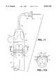
- FIG. 2is an enlarged view in perspective showing a device embodying principles of the invention for implementing the revascularization procedure of FIG. 1, with different positions of the probe member shown in phantom.
- FIG. 3Ais an enlarged fragmentary view in section of the device shown in FIG. 2 showing details of the rotatable nose portion of the body including the internal ratchet mechanism.
- FIG. 3Bis a view similar to FIG. 3A showing the nose portion of the body with a detent wheel of the ratchet mechanism in its retracted position.
- FIG. 4is an exploded fragmentary view showing the detent wheel for the ratchet mechanism with a portion of the body having a fixed ratchet tooth.
- FIG. 5Ais an end view of the detent wheel taken along line 5A--5A of FIG. 4.
- FIG. 5Bis an opposite end view of the detent wheel taken along line 5B--5B of FIG. 4.
- FIG. 6is an exploded view in perspective showing the nose-piece and the detent wheel for the device of FIG. 3A.
- FIG. 7is a view in section of the nose piece taken along line 7--7 of FIG. 3A.
- FIG. 8is a fragmentary exploded view in elevation of the probe shaft and its distal end assembly.
- FIG. 8Ais a fragmentary view in section showing the distal end of FIG. 8 fully assembled.
- FIG. 8Bis a fragmentary view in section showing a modified distal end assembly.
- FIG. 8Cis a fragmentary view in section showing a modified distal end assembly without an end liner.
- FIG. 8Dis a view in section taken along line 8D--8D of FIG. 8.
- FIG. 9is a fragmentary end view of the device showing the control button in a first position after it has completed a TMR procedure involving minimum travel of the fiber bundle and indicating the extension of the optical fiber element from the distal end of the probe.
- FIG. 9Ais a view in cross section taken along line 9A--9A of FIG. 9.
- FIG. 10is a view similar to FIG. 9 showing the stop member and control button after completing a TMR procedure when set for an intermediate travel distance for the fiber bundle.
- FIG. 10Ais a view in cross section taken along line 10A--10A of FIG. 10.
- FIG. 11is a view similar to FIG. 9 showing the stop member and control button of the present device after completing a TMR procedure set for maximum travel of the fiber bundle.
- FIG. 11Ais a view in cross section taken along line 11A--11A of FIG. 11.
- FIG. 1diagrammatically depicts a human heart 10 with the epicardium 12 of the left ventricle 14 exposed where a Trans-Myocardial Revascularization (TMR) procedure according to the invention is to be performed.
- TMRTrans-Myocardial Revascularization
- the surgeonmakes an incision in the patient's chest to expose the outer wall of the heart's left ventricle.
- the wall of the left ventricleis comprised of an outer layer, the epicardium, the main muscle thickness or myocardium, and the inner layer or endocardium.
- the epicardiumis comprised of a smooth, moist serous membrane which is somewhat tougher than the other tissue layers of the heart muscle.
- the surgeonutilizes a hand-held device 16 which is manipulated to contact the outer surface of the patient's heart in the left ventricle area and form a series of revascularization channels 18 in the myocardium of the heart tissue at selected spaced apart locations.
- Such channelsallow more blood to flow into the heart muscle causing capillary regenesis and ultimate strengthening of the heart muscle.
- each of the channelsis formed by first penetrating the epicardium membrane with a tubular piercing element 25 to form a relatively small opening through which at least a portion of the distal end of an optical fiber bundle 26 can thereafter be forced to engage the myocardium.
- the fiber bundleis connected to a laser energy source 28 at its proximal end. Once through this epicardial opening, a beam of laser energy is emitted in pulses from the distal end of the fiber bundle 26 as it is moved forwardly to form the channel 18 or pocket in the myocardium and in most cases completely through the endocardium.
- the distal end of the fiber bundleis retracted to a position within the end member of the device 16 which is then moved to another location to repeat the procedure.
- a number of channelse.g. up to 60, may be formed depending on the patient's condition.
- the device 16comprises a housing body 20 adapted to be hand-held by the surgeon during an operative procedure.
- a generally J-shaped neck or probe member 22is attached to a rotatable nose piece 23 attached to the forward end of the housing body 20 so that the probe member 22 can be rotated to different positions as shown in FIG. 2.
- a detachable enlarged head member 24that surrounds the piercing element 25 and has a disk like shape with a yieldable lining 27 for cushioning contact with the outer surface of the epicardial membrane and for irrigating the TMR site with a solution such as sterile saline or lactated ringers.
- the optical fiber bundle 26whose proximal end is connected to the laser source 28 extends through the housing and through the neck member to the distal head member 24.
- the fiber bundle 26is connected to a movable shuttle 30 (FIGS. 3A and 3B) which is connected to the thumb actuated fiber moving control button 32. Movement of the control button 32 by the surgeon will move the distal end 34 of the fiber bundle forwardly beyond the distal head member 24.
- meansare provided in conjunction with the control button 32 for limiting its travel and thus controlling the extension of the tip of the fiber bundle to a selected distance during each procedure.
- a flexible conduit 31 extending from the vacuum source 37is connected to the vacuum fitting of a conventional stopcock valve 33 that is connected to the rear end of the suction/irrigation hose 36 and communicates with one or more air passages around the fiber bundle that extends to and through the distal head member 24.
- a conduit 35is attached to an irrigant supply 43.
- This suction forcedraws the epicardial tissue firmly against the distal head member 24 so that the piercing element 25 can make a relatively small opening in the epicardial muscle fibers to allow the distal end 34 of the fiber bundle 26 to penetrate and engage the myocardium.
- the suctionfurther allows additional anchoring of the device to the heart.
- lactated Ringers or other sterile irrigant from the source 43is applied to the nose piece section, and through the probe and distal head member 24.
- the irrigantmaintains a moist heart surface during a TMR procedure, and flushes the vacuum/irrigation channel 69 within the body of the device.
- the housing body 20may be comprised of assembled components molded from a suitable plastic material. In general, it comprises a central portion 38 that houses the shuttle 30 and the control button 32. A molded rubber rear end portion 39 extends at an angle from the control portion and provides strain relieved access holes for the suction/irrigation hose 36 and the fiber bundle 26.
- the rotatable nose piece 23At the forward end of the body 20 is the rotatable nose piece 23 which enables the attached J-shaped probe 22 and its distal head member 24 to be turned up to 360° in a desired direction.
- the exterior of the central member 38is provided with elongated recesses 40 on opposite sides to enable it to be gripped firmly, and the nose piece is provided with similar slight depressions 41 on opposite sides of an outwardly extending control fin 42.
- the internal shuttle 30is bonded to the fiber bundle 26 and is connected by a web position 44 to the control button 32 which extends through and is movable within a slot 45 (FIG. 2) in the body wall.
- a tubular plastic conduit 46is attached to an internal barb 47 forming a suction/irrigation passage 48 that extends through the nose piece 23 and the probe member to its distal head member 24.
- the nose piecewhich is tapered forwardly, is combined with other interior components to form a ratchet means that enables it and thus the probe member 22 to be rotatively indexed in increments and to stay in a selected position when rotated by the surgeon.
- FIG. 1the internal shuttle 30 is bonded to the fiber bundle 26 and is connected by a web position 44 to the control button 32 which extends through and is movable within a slot 45 (FIG. 2) in the body wall.
- a tubular plastic conduit 46is attached to an internal barb 47 forming a suction/irrigation passage 48 that extends through the nose piece 23 and the
- the tubular probe member 22extends through and is bonded to a series of cruciform internal fins 56 at the forward end of the nose-piece 23.
- One of the cruciform fins 56has a spline member 57 as shown in FIG. 7 which engages into a slotted opening in the tubular probe member 22.
- the splinemaintains correct orientation of the J-shaped probe to the nose-piece during assembly, and reinforces the adhesive bond against rotational force during use.
- the end of the probe memberextends within and is bonded to the surface of a central bore 49 of a detent wheel 50. As shown in FIG. 5A this detent wheel has an enlarged flange portion 51 having a series of blunt cogs or teeth 52 separated by spaces 53.
- tubular portion 54Extending forwardly from the flange portion is an integral tubular portion 54, which fits around and slides over the outer surface of the inner end of the probe member 22.
- the end of tubular portion 54is provided with cruciform slots 55 that mesh with cruciform internal fins 56 within the end of the nose-piece 23.
- a tubular sleeve 58Spaced outside of and coaxial with the detent wheel 50 is a tubular sleeve 58 having radially outwardly extending end flange 59.
- the forward end of this sleevebears against the cruciform fins of the nose-piece 23 and in this position, the end flange 59 retains an O-ring 60 between it and an end flange 61 of the central body member 38.
- the O-ring 60maintains a compression fit between the nose-piece and the control body while allowing ready rotation of the nose-piece.
- a coiled spring 62which normally urges the end flange 51 of the detent wheel 50 away from the sleeve flange 59.
- the fixed tooth 64 or the body interiorbears against a tapered tooth 52 of the detent wheel 50 and creates a camming action that moves the detent wheel axially against the spring 62.
- This relatively simple mechanical ratchet systemenables the device user to rotate the probe element 22 and its distal end 24 to any desired position with a positive action that produces a responsive ratchet click which indicates that with no pressure on the fin, the nose-piece and probe member will remain in the desired set position.
- a supporting tube 65is provided within the body and its nose-piece 23. As shown in FIG. 3A, with the fiber moving control button pushed fully distally, this tube extends from the shuttle 30 forwardly and somewhat beyond the forward end of the nose-piece. It is made of semi-rigid material and fits around the fiber bundle 26, being sized to provide an easy sliding clearance within the probe member 22. It is co-axial with the probe member 22 which has a larger diameter so that an annular suction/irrigation passage 48 is provided around it.
- the enlarged distal head member 24 on the J-shaped probe member 22 as shown in FIG. 8 and 8A,provides a means for quick attachment and replacement of optional distal head members whenever it is necessary.
- the device 16may utilize different distal head member configurations as shown in FIGS. 8-8C.
- a distal head member 24is provided having a piercing tip 25, a foam lining 27 and suction/irrigation passages 69.
- a distal head 24Ais shown without a piercing tip and without an irrigation lining.
- a distal head embodiment 24Cis shown which has a tip member 25C but no irrigation liner.
- All of the distal head membersutilize Luer style fittings to enable quick attachment and removal.
- a standard male Luer connector sleeve 66is bonded to the distal end of the probe member.
- Each of the distal head membersincludes a tubular female Luer fitting 68 which receives the male Luer connector sleeve 66.
- a Luer retaining nut 74is moved into place and twisted onto the Luer threads of the tubular female Luer fitting and twisted to hold the distal head member assembly to the probe member assembly.
- the piercing suction irrigation tipis comprised of a tubular female Luer into which is bonded the piercing tip 25.
- the tubular holder 67has a large bore 68 at one end to receive the male Luer connecting sleeve 66, and the tubular piercing tip 25 extends from its lower end.
- a series of channels 69which are generally parallel to the axis of the tip holder extend from the bore 68 to its lower end 70 which is within the concave cup area of the head member 24A, thereby communicating the suction or irrigation to the area where the epicardium is penetrated during a TMR procedure.
- the piercing tip 25, preferably made of 304 Hypodermic stainless steelis tubular with its outer, or lower end beveled at something less than 60°.
- the inside edge of the piercing tipis slightly radiused, and the distal tip is flared approximately 0.005" to allow fiber movement without restriction.
- the proximal end of the piercing tip 25is slightly flared to mechanically prevent the tip from falling out of the tubular female Luer fitting 67, and is also bonded to the fitting.
- the piercing tip head member 24Afurther includes a conical disk member 71 with a central opening 72 which receives the lower end 70 of the female Luer fitting 67 and is surrounded by a smooth inner concave surface 73.
- the irrigation tip head memberis identical to a plain suction/irrigation tip with the additional layer 27 of medical grade, plastic foam material bonded to the conical disc member.
- This foam layerhas a central opening and preferably extends outwardly from the cup member to provide a means for cushioning the contact of the head member 24A with the heart surface. It also provides a means for applying a liquid solution such as irrigants and/or drugs to the heart surface when necessary during the TMR procedure.
- the tip holder 67When the distal head 24 is assembled for use as shown in FIG. 8A, the tip holder 67 is retained by the lower end portion 70 which extends through the central opening 72 of the disk member. The piercing tip 25 extends through the opening in the plastic foam liner material 27 on the inner concave surface of disk member. Now, the tip holder 67 is pushed into the Luer sleeve connector 66 on the J-shaped probe member 22 and a Luer retainer nut 74 is moved into place and twisted to hold the assembly together. As shown, when assembled the beveled end of the piercing tip 25 extends just slightly beyond the outer surface of the foam layer 27.
- the device 16is provided with a means for controlling the amount or distance of travel for the control button 32 and thus the distance that the distal tip 34 of the fiber bundle 26 will move from the distal head 24 of the J-shaped probe member 22 during a typical TMR procedure.
- the control button 32 on the body 20is in its rearward or starting position, that is, at the rear of the slot 45 in the body. Spaced from the rear end of the slot and to the right side of it is a first projection or stop member 76 that is integral with the body and extends outwardly therefrom. Further forward of stop member 76 and to the left side of the slot 45 on the body 20 is a second projection or stop member 78.
- the projections 76 and 78serve as stops to limit the travel of the control button 32 to two preset travel distances.
- an arcuate member 80having a curvature that conforms to the outer cylindrical surface of the upper side of the body 20, extends through the control button 32 on a line that is transverse to its direction of movement, i.e. the longitudinal axis of the body 20.
- At the ends of the arcuate member 80are upwardly extending projections 81 and 82.
- the arcuate member 80defines a slot 83 which locally decreases stiffness to create a leaf spring with fixed ends.
- the arcuate member 80defines in the leaf spring area a small projection 87 which fits within a mating recess 89 in the button when the arcuate member 80 is centered as shown in FIG. 11.
- the projection 87moves out of the recess and deflects the leaf spring until the member is returned to the centered position. The force created by the deflection creates frictional drag and resistance to positional change of the arcuate member.
- the left end projection 82engages the left wall of the control button and the right end projection 81 extends outwardly to be in line with the first stop member 76.
- the control button 32can be moved only a preselected distance (e.g. 2.5 centimeters) until the right end projection 81 engages the first stop member 76. This allows the distal tip 34 of the fiber bundle 26 to move the same preselected distance from the surface of the distal end assembly 24 of the probe member 22.
- the arcuate member 80is shown when pushed to the left so that its left end projection 82 will engage the second stop member 78. This position of the arcuate member limits the travel of the control button and thus the tip 34 of the fiber bundle 26 to a selected intermediate distance, e.g. (3 centimeters).
- the control buttoncan be moved its full travel distance which is limited only by the length of the slot 45.
- the device 16 in a typical TMR operationshould be readily apparent from the foregoing description.
- the deviceis gripped and maneuvered by the surgeon, using the rotatable nose-piece 23 and attached probe member controlled by the nose fin, so that the distal head member of the probe can engage the desired target area of the patient's beating heart.
- the ratchet systemallows firm positioning of the probe member at any selected position by applying side pressure to the nose-piece fin member.
- the surgeoncan move the distal tip 34 of the optical fiber bundle forwardly by pushing the control button 32. Simultaneously, the surgeon can activate the laser source with an appropriate switch such as a foot switch (not shown), thereby causing laser pulses to be emitted from the distal tip 34 as it moves forward. Prior to the procedure, the surgeon can preset the amount of travel of the distal tip by moving the arcuate member 80 on the control button to either or none of the stop members 76 and 78.
- the proximal end of the optical fiber bundle 26is connected to the source or generator 28 of laser energy which is preferably a Holmium laser that operates at a wave length in the range of 1.8 to 2.2 microns and a pulse frequency in the range of 2-25 Hertz.
- laser energyis preferably a Holmium laser that operates at a wave length in the range of 1.8 to 2.2 microns and a pulse frequency in the range of 2-25 Hertz.
- a Holmium or Excimer laseris preferable because it provides high absorption efficiency, hemotosis and a moderate absorption range in myocardium tissue, and is compatible with optical fiber delivery.
- laser energyis supplied to the optical fiber bundle 26 which, at its distal end, has a diameter of less than 1.5 mm and sized according to the location and type of laser(s) to be used.
- the optical fiber bundlepreferably is comprised of a plurality (e.g.
- glass fibers 32each having a diameter of 100 microns.
- a suitable bonding or potting materialsuch as a 353 ND Epoxy
- the bundleis preferably surrounded by an annular tantalum marker which serves to retain the bundle in a closely packed geometric boundary.
- a plastic protective sheathsuch as polypropelene having a wall thickness of 0.004 inches.
- Other fiber bundle configurations or a single fibercould be used within the scope of the invention.
- the probe member 22 of the device 16is a tubular member preferably made from stainless steel and having a uniform outside diameter (e.g. 0.120 inches), an inside diameter (e.g. 0.094 inches) and bent into an angular "J" shape within which the optical fiber bundle 26 is slidable.
- the present inventionprovides an improved laser surgery device for performing TMR procedures that is particularly easy to manipulate and maneuver during use and has adjustment features which increase its versatility and efficiency in the formation of effective channels for revascularization.
- the fibermay be a single fiber or other fiber bundle arrangements may be used, and the laser energy may be provided by other lasers.
- the stop mechanismmay include more or less stops and other conventional means may be used for controlling the distance of travel of the fiber.
Landscapes
- Health & Medical Sciences (AREA)
- Life Sciences & Earth Sciences (AREA)
- Surgery (AREA)
- General Health & Medical Sciences (AREA)
- Veterinary Medicine (AREA)
- Biomedical Technology (AREA)
- Heart & Thoracic Surgery (AREA)
- Medical Informatics (AREA)
- Molecular Biology (AREA)
- Animal Behavior & Ethology (AREA)
- Nuclear Medicine, Radiotherapy & Molecular Imaging (AREA)
- Public Health (AREA)
- Engineering & Computer Science (AREA)
- Physics & Mathematics (AREA)
- Pathology (AREA)
- Optics & Photonics (AREA)
- Electromagnetism (AREA)
- Otolaryngology (AREA)
- Oral & Maxillofacial Surgery (AREA)
- Laser Surgery Devices (AREA)
Abstract
Description
Claims (24)
Priority Applications (1)
| Application Number | Priority Date | Filing Date | Title |
|---|---|---|---|
| US08/790,193US6019756A (en) | 1996-04-05 | 1997-01-30 | Laser device for transmyocardial revascularization procedures |
Applications Claiming Priority (3)
| Application Number | Priority Date | Filing Date | Title |
|---|---|---|---|
| US08/628,456US5782823A (en) | 1996-04-05 | 1996-04-05 | Laser device for transmyocardial revascularization procedures including means for enabling a formation of a pilot hole in the epicardium |
| US08/628,849US5738680A (en) | 1996-04-05 | 1996-04-05 | Laser device with piercing tip for transmyocardial revascularization procedures |
| US08/790,193US6019756A (en) | 1996-04-05 | 1997-01-30 | Laser device for transmyocardial revascularization procedures |
Related Parent Applications (2)
| Application Number | Title | Priority Date | Filing Date |
|---|---|---|---|
| US08/628,456Continuation-In-PartUS5782823A (en) | 1996-04-05 | 1996-04-05 | Laser device for transmyocardial revascularization procedures including means for enabling a formation of a pilot hole in the epicardium |
| US08/628,849Continuation-In-PartUS5738680A (en) | 1996-04-05 | 1996-04-05 | Laser device with piercing tip for transmyocardial revascularization procedures |
Publications (1)
| Publication Number | Publication Date |
|---|---|
| US6019756Atrue US6019756A (en) | 2000-02-01 |
Family
ID=27090713
Family Applications (1)
| Application Number | Title | Priority Date | Filing Date |
|---|---|---|---|
| US08/790,193Expired - LifetimeUS6019756A (en) | 1996-04-05 | 1997-01-30 | Laser device for transmyocardial revascularization procedures |
Country Status (1)
| Country | Link |
|---|---|
| US (1) | US6019756A (en) |
Cited By (44)
| Publication number | Priority date | Publication date | Assignee | Title |
|---|---|---|---|---|
| US6152918A (en)* | 1996-04-05 | 2000-11-28 | Eclipse Surgical Technologies, Inc. | Laser device with auto-piercing tip for myocardial revascularization procedures |
| US6174307B1 (en)* | 1996-03-29 | 2001-01-16 | Eclipse Surgical Technologies, Inc. | Viewing surgical scope for minimally invasive procedures |
| US6176856B1 (en)* | 1998-12-18 | 2001-01-23 | Eclipse Surgical Technologies, Inc | Resistive heating system and apparatus for improving blood flow in the heart |
| US6363939B1 (en) | 1996-06-19 | 2002-04-02 | Wilk Patent Development Corp. | Coronary artery by-pass method |
| US20030083682A1 (en)* | 2001-10-29 | 2003-05-01 | Heise Sean R. | Ultrasonic revasculizer |
| WO2003037203A3 (en)* | 2001-10-29 | 2003-10-30 | Edwards Lifesciences Corp | Method and apparatus for providing medicament to tissue |
| US20030216719A1 (en)* | 2001-12-12 | 2003-11-20 | Len Debenedictis | Method and apparatus for treating skin using patterns of optical energy |
| US6669691B1 (en) | 2000-07-18 | 2003-12-30 | Scimed Life Systems, Inc. | Epicardial myocardial revascularization and denervation methods and apparatus |
| US20040116912A1 (en)* | 2002-12-11 | 2004-06-17 | Appling William M. | Endovascular laser treatment device |
| US20060122584A1 (en)* | 2004-10-27 | 2006-06-08 | Bommannan D B | Apparatus and method to treat heart disease using lasers to form microchannels |
| US20060167531A1 (en)* | 2005-01-25 | 2006-07-27 | Michael Gertner | Optical therapies and devices |
| US20080154296A1 (en)* | 2006-12-22 | 2008-06-26 | The Spectranetics Corporation | Tissue Separating Systems and Methods |
| US20080154293A1 (en)* | 2006-12-22 | 2008-06-26 | The Spectranetics Corporation | Retractable Separating Systems and Methods |
| US20080161782A1 (en)* | 2006-10-26 | 2008-07-03 | Reliant Technologies, Inc. | Micropore delivery of active substances |
| US20080208180A1 (en)* | 2002-07-10 | 2008-08-28 | Cartier William A | Endovascular treatment sheath having a heat insulative tip and method for using the same |
| US20090118720A1 (en)* | 2001-12-12 | 2009-05-07 | Reliant Technologies, Inc. | Dermatological Apparatus and Method |
| US20100292783A1 (en)* | 2009-05-13 | 2010-11-18 | Sorin Biomedica Cardio S.R.L. | Device for surgical interventions |
| US20110282342A1 (en)* | 2010-05-10 | 2011-11-17 | Giovanni Leo | Irrigated finned ablation head |
| US8808367B2 (en) | 2007-09-07 | 2014-08-19 | Sorin Group Italia S.R.L. | Prosthetic valve delivery system including retrograde/antegrade approach |
| US9056008B2 (en) | 2006-12-19 | 2015-06-16 | Sorin Group Italia S.R.L. | Instrument and method for in situ development of cardiac valve prostheses |
| US9283040B2 (en) | 2013-03-13 | 2016-03-15 | The Spectranetics Corporation | Device and method of ablative cutting with helical tip |
| US9291663B2 (en) | 2013-03-13 | 2016-03-22 | The Spectranetics Corporation | Alarm for lead insulation abnormality |
| US9413896B2 (en) | 2012-09-14 | 2016-08-09 | The Spectranetics Corporation | Tissue slitting methods and systems |
| USD765243S1 (en) | 2015-02-20 | 2016-08-30 | The Spectranetics Corporation | Medical device handle |
| US9456872B2 (en) | 2013-03-13 | 2016-10-04 | The Spectranetics Corporation | Laser ablation catheter |
| USD770616S1 (en) | 2015-02-20 | 2016-11-01 | The Spectranetics Corporation | Medical device handle |
| US9603618B2 (en) | 2013-03-15 | 2017-03-28 | The Spectranetics Corporation | Medical device for removing an implanted object |
| US9668765B2 (en) | 2013-03-15 | 2017-06-06 | The Spectranetics Corporation | Retractable blade for lead removal device |
| US9883885B2 (en) | 2013-03-13 | 2018-02-06 | The Spectranetics Corporation | System and method of ablative cutting and pulsed vacuum aspiration |
| US9925366B2 (en) | 2013-03-15 | 2018-03-27 | The Spectranetics Corporation | Surgical instrument for removing an implanted object |
| US9980743B2 (en) | 2013-03-15 | 2018-05-29 | The Spectranetics Corporation | Medical device for removing an implanted object using laser cut hypotubes |
| US10058313B2 (en) | 2011-05-24 | 2018-08-28 | Sorin Group Italia S.R.L. | Transapical valve replacement |
| US10136913B2 (en) | 2013-03-15 | 2018-11-27 | The Spectranetics Corporation | Multiple configuration surgical cutting device |
| US10383691B2 (en) | 2013-03-13 | 2019-08-20 | The Spectranetics Corporation | Last catheter with helical internal lumen |
| US10405924B2 (en) | 2014-05-30 | 2019-09-10 | The Spectranetics Corporation | System and method of ablative cutting and vacuum aspiration through primary orifice and auxiliary side port |
| US10448999B2 (en) | 2013-03-15 | 2019-10-22 | The Spectranetics Corporation | Surgical instrument for removing an implanted object |
| US20200163664A1 (en)* | 2013-08-30 | 2020-05-28 | Bioventrix, Inc. | Cardiac tissue anchoring devices, methods, and systems for treatment of congestive heart failure and other conditions |
| US10835279B2 (en) | 2013-03-14 | 2020-11-17 | Spectranetics Llc | Distal end supported tissue slitting apparatus |
| US10842532B2 (en) | 2013-03-15 | 2020-11-24 | Spectranetics Llc | Medical device for removing an implanted object |
| CN114110114A (en)* | 2021-12-24 | 2022-03-01 | 杭州佳量医疗科技有限公司 | One-way stepping device and driving system for optical fiber conduit |
| US11504231B2 (en) | 2018-05-23 | 2022-11-22 | Corcym S.R.L. | Cardiac valve prosthesis |
| US20230149042A1 (en)* | 2021-11-16 | 2023-05-18 | Mukesh Gupta | Needle and cannula assembly for cannulation and treatment of subcutaneous vessels |
| US12053203B2 (en) | 2014-03-03 | 2024-08-06 | Spectranetics, Llc | Multiple configuration surgical cutting device |
| US12318289B2 (en) | 2018-05-23 | 2025-06-03 | Corcym S.R.L. | Device for the in-situ delivery of heart valve prosthesis |
Citations (5)
| Publication number | Priority date | Publication date | Assignee | Title |
|---|---|---|---|---|
| US4846171A (en)* | 1986-10-06 | 1989-07-11 | Gv Medical, Inc. | Laser catheter adjustable control apparatus |
| EP0515867A2 (en)* | 1991-05-01 | 1992-12-02 | The Trustees Of Columbia University In The City Of New York | Myocardial revascularization through the endocardial surface using a laser |
| WO1994014383A1 (en)* | 1992-12-22 | 1994-07-07 | Laser Engineering, Inc. | Handpiece for transmyocardial vascularization heart-synchronized pulsed laser system |
| WO1995017127A1 (en)* | 1993-12-23 | 1995-06-29 | Oticon A/S | Method and instrument for establishing the receiving site of a coronary artery bypass graft |
| WO1996039964A1 (en)* | 1995-06-07 | 1996-12-19 | Cardiogenesis Corporation | Probe for myocardial channel formation |
- 1997
- 1997-01-30USUS08/790,193patent/US6019756A/ennot_activeExpired - Lifetime
Patent Citations (5)
| Publication number | Priority date | Publication date | Assignee | Title |
|---|---|---|---|---|
| US4846171A (en)* | 1986-10-06 | 1989-07-11 | Gv Medical, Inc. | Laser catheter adjustable control apparatus |
| EP0515867A2 (en)* | 1991-05-01 | 1992-12-02 | The Trustees Of Columbia University In The City Of New York | Myocardial revascularization through the endocardial surface using a laser |
| WO1994014383A1 (en)* | 1992-12-22 | 1994-07-07 | Laser Engineering, Inc. | Handpiece for transmyocardial vascularization heart-synchronized pulsed laser system |
| WO1995017127A1 (en)* | 1993-12-23 | 1995-06-29 | Oticon A/S | Method and instrument for establishing the receiving site of a coronary artery bypass graft |
| WO1996039964A1 (en)* | 1995-06-07 | 1996-12-19 | Cardiogenesis Corporation | Probe for myocardial channel formation |
Cited By (88)
| Publication number | Priority date | Publication date | Assignee | Title |
|---|---|---|---|---|
| US6174307B1 (en)* | 1996-03-29 | 2001-01-16 | Eclipse Surgical Technologies, Inc. | Viewing surgical scope for minimally invasive procedures |
| US6152918A (en)* | 1996-04-05 | 2000-11-28 | Eclipse Surgical Technologies, Inc. | Laser device with auto-piercing tip for myocardial revascularization procedures |
| US6363939B1 (en) | 1996-06-19 | 2002-04-02 | Wilk Patent Development Corp. | Coronary artery by-pass method |
| US20020092535A1 (en)* | 1996-06-19 | 2002-07-18 | Wilk Patent Development Corp. | Coronary artery by-pass method |
| US6176856B1 (en)* | 1998-12-18 | 2001-01-23 | Eclipse Surgical Technologies, Inc | Resistive heating system and apparatus for improving blood flow in the heart |
| US20040082949A1 (en)* | 2000-07-18 | 2004-04-29 | Taimisto Miriam H. | Epicardial myocardial revascularization and denervation methods and apparatus |
| US6669691B1 (en) | 2000-07-18 | 2003-12-30 | Scimed Life Systems, Inc. | Epicardial myocardial revascularization and denervation methods and apparatus |
| US7063696B2 (en) | 2000-07-18 | 2006-06-20 | Boston Scientific Scimed, Inc. | Epicardial myocardial revascularization and denervation methods and apparatus |
| WO2003037203A3 (en)* | 2001-10-29 | 2003-10-30 | Edwards Lifesciences Corp | Method and apparatus for providing medicament to tissue |
| US20030083682A1 (en)* | 2001-10-29 | 2003-05-01 | Heise Sean R. | Ultrasonic revasculizer |
| US7776025B2 (en) | 2001-10-29 | 2010-08-17 | Edwards Lifesciences Corporation | Method for providing medicament to tissue |
| US20030216719A1 (en)* | 2001-12-12 | 2003-11-20 | Len Debenedictis | Method and apparatus for treating skin using patterns of optical energy |
| US20090118720A1 (en)* | 2001-12-12 | 2009-05-07 | Reliant Technologies, Inc. | Dermatological Apparatus and Method |
| US20080208180A1 (en)* | 2002-07-10 | 2008-08-28 | Cartier William A | Endovascular treatment sheath having a heat insulative tip and method for using the same |
| US20040116912A1 (en)* | 2002-12-11 | 2004-06-17 | Appling William M. | Endovascular laser treatment device |
| US20060142747A1 (en)* | 2002-12-11 | 2006-06-29 | Appling William M | Method of thermally treating blood vessels |
| US7033347B2 (en) | 2002-12-11 | 2006-04-25 | Angiodynamics, Inc. | Endovascular laser treatment device |
| US8413664B2 (en) | 2002-12-11 | 2013-04-09 | Angiodynamics, Inc. | Method of thermally treating blood vessels |
| US20060122584A1 (en)* | 2004-10-27 | 2006-06-08 | Bommannan D B | Apparatus and method to treat heart disease using lasers to form microchannels |
| US20060167531A1 (en)* | 2005-01-25 | 2006-07-27 | Michael Gertner | Optical therapies and devices |
| US20080161782A1 (en)* | 2006-10-26 | 2008-07-03 | Reliant Technologies, Inc. | Micropore delivery of active substances |
| US9056008B2 (en) | 2006-12-19 | 2015-06-16 | Sorin Group Italia S.R.L. | Instrument and method for in situ development of cardiac valve prostheses |
| US9289226B2 (en) | 2006-12-22 | 2016-03-22 | The Spectranetics Corporation | Retractable separating systems and methods |
| US20080154296A1 (en)* | 2006-12-22 | 2008-06-26 | The Spectranetics Corporation | Tissue Separating Systems and Methods |
| US9808275B2 (en) | 2006-12-22 | 2017-11-07 | The Spectranetics Corporation | Retractable separating systems and methods |
| US9801650B2 (en) | 2006-12-22 | 2017-10-31 | The Spectranetics Corporation | Tissue separating systems and methods |
| US8961551B2 (en) | 2006-12-22 | 2015-02-24 | The Spectranetics Corporation | Retractable separating systems and methods |
| US9028520B2 (en) | 2006-12-22 | 2015-05-12 | The Spectranetics Corporation | Tissue separating systems and methods |
| US20080154293A1 (en)* | 2006-12-22 | 2008-06-26 | The Spectranetics Corporation | Retractable Separating Systems and Methods |
| US10537354B2 (en) | 2006-12-22 | 2020-01-21 | The Spectranetics Corporation | Retractable separating systems and methods |
| US10869687B2 (en) | 2006-12-22 | 2020-12-22 | Spectranetics Llc | Tissue separating systems and methods |
| US8808367B2 (en) | 2007-09-07 | 2014-08-19 | Sorin Group Italia S.R.L. | Prosthetic valve delivery system including retrograde/antegrade approach |
| US20100292783A1 (en)* | 2009-05-13 | 2010-11-18 | Sorin Biomedica Cardio S.R.L. | Device for surgical interventions |
| US9168105B2 (en)* | 2009-05-13 | 2015-10-27 | Sorin Group Italia S.R.L. | Device for surgical interventions |
| US9179968B2 (en)* | 2010-05-10 | 2015-11-10 | St. Jude Medical Luxembourg Holding S.À.R.L. | Irrigated finned ablation head |
| US20110282342A1 (en)* | 2010-05-10 | 2011-11-17 | Giovanni Leo | Irrigated finned ablation head |
| US10631926B2 (en) | 2010-05-10 | 2020-04-28 | St. Jude Medical International Holding S.À R.L. | Irrigated finned ablation head |
| US10058313B2 (en) | 2011-05-24 | 2018-08-28 | Sorin Group Italia S.R.L. | Transapical valve replacement |
| US10531891B2 (en) | 2012-09-14 | 2020-01-14 | The Spectranetics Corporation | Tissue slitting methods and systems |
| US10368900B2 (en) | 2012-09-14 | 2019-08-06 | The Spectranetics Corporation | Tissue slitting methods and systems |
| US9724122B2 (en) | 2012-09-14 | 2017-08-08 | The Spectranetics Corporation | Expandable lead jacket |
| US9763692B2 (en) | 2012-09-14 | 2017-09-19 | The Spectranetics Corporation | Tissue slitting methods and systems |
| US11596435B2 (en) | 2012-09-14 | 2023-03-07 | Specrtranetics Llc | Tissue slitting methods and systems |
| US9413896B2 (en) | 2012-09-14 | 2016-08-09 | The Spectranetics Corporation | Tissue slitting methods and systems |
| US9949753B2 (en) | 2012-09-14 | 2018-04-24 | The Spectranetics Corporation | Tissue slitting methods and systems |
| US9883885B2 (en) | 2013-03-13 | 2018-02-06 | The Spectranetics Corporation | System and method of ablative cutting and pulsed vacuum aspiration |
| US10265520B2 (en) | 2013-03-13 | 2019-04-23 | The Spetranetics Corporation | Alarm for lead insulation abnormality |
| US9925371B2 (en) | 2013-03-13 | 2018-03-27 | The Spectranetics Corporation | Alarm for lead insulation abnormality |
| US9937005B2 (en) | 2013-03-13 | 2018-04-10 | The Spectranetics Corporation | Device and method of ablative cutting with helical tip |
| US9283040B2 (en) | 2013-03-13 | 2016-03-15 | The Spectranetics Corporation | Device and method of ablative cutting with helical tip |
| US9291663B2 (en) | 2013-03-13 | 2016-03-22 | The Spectranetics Corporation | Alarm for lead insulation abnormality |
| US10799293B2 (en) | 2013-03-13 | 2020-10-13 | The Spectranetics Corporation | Laser ablation catheter |
| US9456872B2 (en) | 2013-03-13 | 2016-10-04 | The Spectranetics Corporation | Laser ablation catheter |
| US10485613B2 (en) | 2013-03-13 | 2019-11-26 | The Spectranetics Corporation | Device and method of ablative cutting with helical tip |
| US10383691B2 (en) | 2013-03-13 | 2019-08-20 | The Spectranetics Corporation | Last catheter with helical internal lumen |
| US11925380B2 (en) | 2013-03-14 | 2024-03-12 | Spectranetics Llc | Distal end supported tissue slitting apparatus |
| US10835279B2 (en) | 2013-03-14 | 2020-11-17 | Spectranetics Llc | Distal end supported tissue slitting apparatus |
| US10524817B2 (en) | 2013-03-15 | 2020-01-07 | The Spectranetics Corporation | Surgical instrument including an inwardly deflecting cutting tip for removing an implanted object |
| US9980743B2 (en) | 2013-03-15 | 2018-05-29 | The Spectranetics Corporation | Medical device for removing an implanted object using laser cut hypotubes |
| US10314615B2 (en) | 2013-03-15 | 2019-06-11 | The Spectranetics Corporation | Medical device for removing an implanted object |
| US11925334B2 (en) | 2013-03-15 | 2024-03-12 | Spectranetics Llc | Surgical instrument for removing an implanted object |
| US9603618B2 (en) | 2013-03-15 | 2017-03-28 | The Spectranetics Corporation | Medical device for removing an implanted object |
| US10136913B2 (en) | 2013-03-15 | 2018-11-27 | The Spectranetics Corporation | Multiple configuration surgical cutting device |
| US9925366B2 (en) | 2013-03-15 | 2018-03-27 | The Spectranetics Corporation | Surgical instrument for removing an implanted object |
| US10448999B2 (en) | 2013-03-15 | 2019-10-22 | The Spectranetics Corporation | Surgical instrument for removing an implanted object |
| US9668765B2 (en) | 2013-03-15 | 2017-06-06 | The Spectranetics Corporation | Retractable blade for lead removal device |
| US9918737B2 (en) | 2013-03-15 | 2018-03-20 | The Spectranetics Corporation | Medical device for removing an implanted object |
| US11160579B2 (en) | 2013-03-15 | 2021-11-02 | Spectranetics Llc | Multiple configuration surgical cutting device |
| US10052129B2 (en) | 2013-03-15 | 2018-08-21 | The Spectranetics Corporation | Medical device for removing an implanted object |
| US9956399B2 (en) | 2013-03-15 | 2018-05-01 | The Spectranetics Corporation | Medical device for removing an implanted object |
| US10849603B2 (en) | 2013-03-15 | 2020-12-01 | Spectranetics Llc | Surgical instrument for removing an implanted object |
| US10842532B2 (en) | 2013-03-15 | 2020-11-24 | Spectranetics Llc | Medical device for removing an implanted object |
| US10219819B2 (en) | 2013-03-15 | 2019-03-05 | The Spectranetics Corporation | Retractable blade for lead removal device |
| US11540822B2 (en)* | 2013-08-30 | 2023-01-03 | Bioventrix, Inc. | Cardiac tissue anchoring devices, methods, and systems for treatment of congestive heart failure and other conditions |
| US20200163664A1 (en)* | 2013-08-30 | 2020-05-28 | Bioventrix, Inc. | Cardiac tissue anchoring devices, methods, and systems for treatment of congestive heart failure and other conditions |
| US12053203B2 (en) | 2014-03-03 | 2024-08-06 | Spectranetics, Llc | Multiple configuration surgical cutting device |
| US10405924B2 (en) | 2014-05-30 | 2019-09-10 | The Spectranetics Corporation | System and method of ablative cutting and vacuum aspiration through primary orifice and auxiliary side port |
| USD770616S1 (en) | 2015-02-20 | 2016-11-01 | The Spectranetics Corporation | Medical device handle |
| USD806245S1 (en) | 2015-02-20 | 2017-12-26 | The Spectranetics Corporation | Medical device handle |
| USD819204S1 (en) | 2015-02-20 | 2018-05-29 | The Spectranetics Corporation | Medical device handle |
| USD854682S1 (en) | 2015-02-20 | 2019-07-23 | The Spectranetics Corporation | Medical device handle |
| USD765243S1 (en) | 2015-02-20 | 2016-08-30 | The Spectranetics Corporation | Medical device handle |
| US11504231B2 (en) | 2018-05-23 | 2022-11-22 | Corcym S.R.L. | Cardiac valve prosthesis |
| US11969341B2 (en) | 2018-05-23 | 2024-04-30 | Corcym S.R.L. | Cardiac valve prosthesis |
| US12318289B2 (en) | 2018-05-23 | 2025-06-03 | Corcym S.R.L. | Device for the in-situ delivery of heart valve prosthesis |
| US20230149042A1 (en)* | 2021-11-16 | 2023-05-18 | Mukesh Gupta | Needle and cannula assembly for cannulation and treatment of subcutaneous vessels |
| CN114110114A (en)* | 2021-12-24 | 2022-03-01 | 杭州佳量医疗科技有限公司 | One-way stepping device and driving system for optical fiber conduit |
| CN114110114B (en)* | 2021-12-24 | 2023-12-01 | 杭州佳量医疗科技有限公司 | An optical fiber catheter unidirectional stepping device and driving system |
Similar Documents
| Publication | Publication Date | Title |
|---|---|---|
| US6019756A (en) | Laser device for transmyocardial revascularization procedures | |
| US5738680A (en) | Laser device with piercing tip for transmyocardial revascularization procedures | |
| US6152918A (en) | Laser device with auto-piercing tip for myocardial revascularization procedures | |
| US5782823A (en) | Laser device for transmyocardial revascularization procedures including means for enabling a formation of a pilot hole in the epicardium | |
| US5703985A (en) | Optical fiber device and method for laser surgery procedures | |
| US5997531A (en) | User actuated laser energy device and procedure for forming a channel within tissue | |
| US5389096A (en) | System and method for percutaneous myocardial revascularization | |
| US5885272A (en) | System and method for percutaneous myocardial revascularization | |
| US6231568B1 (en) | Channel-forming laser energy device | |
| US5941893A (en) | Apparatus for transluminally performing surgery | |
| US6162214A (en) | Corning device for myocardial revascularization | |
| US6200311B1 (en) | Minimally invasive TMR device | |
| US6066131A (en) | Contiguous, branched transmyocardial revascularization (TMR) channel, method and device | |
| US5972012A (en) | Cutting apparatus having articulable tip | |
| US5944686A (en) | Instrument for creating a fluid jet | |
| US6042581A (en) | Transvascular TMR device and method | |
| US6011889A (en) | Piercing point optical fiber device for laser surgery procedures | |
| EP0858779A1 (en) | Transmyocardial revascularisation device | |
| EP1011460A1 (en) | Apparatus and methods for percutaneously performing surgery | |
| CA2220689A1 (en) | System for treating or diagnosing heart tissue | |
| JPH11313827A (en) | Surgical scope for observation used for minimum invasive method | |
| JPH09322900A (en) | Combination type mechanical/optical apparatus for myocardial traverse revascularization | |
| WO1999033510A1 (en) | Fluid jet cutting system for cardiac applications | |
| WO1996039954A1 (en) | Instrument having a selectively shapeable tip for creating a fluid jet | |
| JPH1147147A (en) | Proximate branched trans-myocardial revasculization channel, method and device |
Legal Events
| Date | Code | Title | Description |
|---|---|---|---|
| AS | Assignment | Owner name:ECLIPSE SURGICAL TECHNOLOGIES, INC., CALIFORNIA Free format text:ASSIGNMENT OF ASSIGNORS INTEREST;ASSIGNORS:MUELLER, RICHARD L.;HARMAN, STUART D.;PHIPPS, RICHARD D.;REEL/FRAME:008417/0260;SIGNING DATES FROM 19970128 TO 19970130 | |
| STCF | Information on status: patent grant | Free format text:PATENTED CASE | |
| FEPP | Fee payment procedure | Free format text:PAYOR NUMBER ASSIGNED (ORIGINAL EVENT CODE: ASPN); ENTITY STATUS OF PATENT OWNER: SMALL ENTITY | |
| FPAY | Fee payment | Year of fee payment:4 | |
| FPAY | Fee payment | Year of fee payment:8 | |
| FPAY | Fee payment | Year of fee payment:12 | |
| AS | Assignment | Owner name:GENERAL ELECTRIC CAPITAL CORPORATION, AS AGENT, MA Free format text:SECURITY AGREEMENT;ASSIGNOR:CARDIOGENESIS CORPORATION;REEL/FRAME:026540/0064 Effective date:20110630 | |
| AS | Assignment | Owner name:CRYOLIFE, INC., GEORGIA Free format text:MERGER;ASSIGNOR:CARDIOGENESIS CORPORATION;REEL/FRAME:034723/0249 Effective date:20141231 | |
| AS | Assignment | Owner name:GENERAL ELECTRIC CAPITAL CORPORATION, AS AGENT, MARYLAND Free format text:SECURITY INTEREST;ASSIGNOR:CRYOLIFE, INC.;REEL/FRAME:034947/0248 Effective date:20150209 Owner name:GENERAL ELECTRIC CAPITAL CORPORATION, AS AGENT, MA Free format text:SECURITY INTEREST;ASSIGNOR:CRYOLIFE, INC.;REEL/FRAME:034947/0248 Effective date:20150209 | |
| AS | Assignment | Owner name:HEALTHCARE FINANCIAL SOLUTIONS, LLC, AS SUCCESSOR AGENT, MARYLAND Free format text:ASSIGNMENT OF INTELLECTUAL PROPERTY SECURITY AGREEMENT;ASSIGNOR:GENERAL ELECTRIC CAPITAL CORPORATION, AS RETIRING AGENT;REEL/FRAME:037146/0466 Effective date:20151118 Owner name:HEALTHCARE FINANCIAL SOLUTIONS, LLC, AS SUCCESSOR Free format text:ASSIGNMENT OF INTELLECTUAL PROPERTY SECURITY AGREEMENT;ASSIGNOR:GENERAL ELECTRIC CAPITAL CORPORATION, AS RETIRING AGENT;REEL/FRAME:037146/0466 Effective date:20151118 | |
| AS | Assignment | Owner name:HEALTHCARE FINANCIAL SOLUTIONS, LLC, AS AGENT, MARYLAND Free format text:SECURITY INTEREST;ASSIGNORS:CRYOLIFE, INC., AS GRANTOR;VALVE SPECIAL PURPOSE CO., LLC, AS GRANTOR;ON-X LIFE TECHNOLOGIES, INC., AS GRANTOR;REEL/FRAME:037569/0212 Effective date:20160120 Owner name:HEALTHCARE FINANCIAL SOLUTIONS, LLC, AS AGENT, MAR Free format text:SECURITY INTEREST;ASSIGNORS:CRYOLIFE, INC., AS GRANTOR;VALVE SPECIAL PURPOSE CO., LLC, AS GRANTOR;ON-X LIFE TECHNOLOGIES, INC., AS GRANTOR;REEL/FRAME:037569/0212 Effective date:20160120 | |
| AS | Assignment | Owner name:CARDIOGENESIS CORPORATION (N/K/A CRYOLIFE, INC.), GEORGIA Free format text:RELEASE OF SECURITY INTEREST IN PATENTS;ASSIGNOR:HEALTHCARE FINANCIAL SOLUTIONS, LLC, AS ADMINISTRATIVE AGENT;REEL/FRAME:044621/0240 Effective date:20171201 Owner name:ON-X LIFE TECHNOLOGIES, INC. (F/K/A MCRI, INC.), GEORGIA Free format text:RELEASE OF SECURITY INTEREST IN PATENTS;ASSIGNOR:HEALTHCARE FINANCIAL SOLUTIONS, LLC, AS ADMINISTRATIVE AGENT;REEL/FRAME:044621/0240 Effective date:20171201 Owner name:CRYOLIFE ACQUISITION CORPORATION, GEORGIA Free format text:RELEASE OF SECURITY INTEREST IN PATENTS;ASSIGNOR:HEALTHCARE FINANCIAL SOLUTIONS, LLC, AS ADMINISTRATIVE AGENT;REEL/FRAME:044621/0240 Effective date:20171201 Owner name:CRYOLIFE, INC., GEORGIA Free format text:RELEASE OF SECURITY INTEREST IN PATENTS;ASSIGNOR:HEALTHCARE FINANCIAL SOLUTIONS, LLC, AS ADMINISTRATIVE AGENT;REEL/FRAME:044621/0240 Effective date:20171201 Owner name:ON-X LIFE TECHNOLOGIES, INC. (F/K/A MCRI, INC.), G Free format text:RELEASE OF SECURITY INTEREST IN PATENTS;ASSIGNOR:HEALTHCARE FINANCIAL SOLUTIONS, LLC, AS ADMINISTRATIVE AGENT;REEL/FRAME:044621/0240 Effective date:20171201 Owner name:CARDIOGENESIS CORPORATION (N/K/A CRYOLIFE, INC.), Free format text:RELEASE OF SECURITY INTEREST IN PATENTS;ASSIGNOR:HEALTHCARE FINANCIAL SOLUTIONS, LLC, AS ADMINISTRATIVE AGENT;REEL/FRAME:044621/0240 Effective date:20171201 Owner name:HEMOSPHERE, INC., GEORGIA Free format text:RELEASE OF SECURITY INTEREST IN PATENTS;ASSIGNOR:HEALTHCARE FINANCIAL SOLUTIONS, LLC, AS ADMINISTRATIVE AGENT;REEL/FRAME:044621/0240 Effective date:20171201 Owner name:VALVE SPECIAL PURPOSE CO., LLC, GEORGIA Free format text:RELEASE OF SECURITY INTEREST IN PATENTS;ASSIGNOR:HEALTHCARE FINANCIAL SOLUTIONS, LLC, AS ADMINISTRATIVE AGENT;REEL/FRAME:044621/0240 Effective date:20171201 |