US6019721A - Camera with improved focus mechanism - Google Patents
Camera with improved focus mechanismDownload PDFInfo
- Publication number
- US6019721A US6019721AUS09/094,234US9423498AUS6019721AUS 6019721 AUS6019721 AUS 6019721AUS 9423498 AUS9423498 AUS 9423498AUS 6019721 AUS6019721 AUS 6019721A
- Authority
- US
- United States
- Prior art keywords
- camera
- drive
- coupled
- actuator
- image sensor
- Prior art date
- Legal status (The legal status is an assumption and is not a legal conclusion. Google has not performed a legal analysis and makes no representation as to the accuracy of the status listed.)
- Expired - Lifetime
Links
- 230000007246mechanismEffects0.000titleabstractdescription9
- 230000033001locomotionEffects0.000claimsdescription20
- 238000003384imaging methodMethods0.000claimsdescription9
- 230000015541sensory perception of touchEffects0.000claimsdescription2
- 230000008878couplingEffects0.000description3
- 238000010168coupling processMethods0.000description3
- 238000005859coupling reactionMethods0.000description3
- 239000000463materialSubstances0.000description3
- 230000003287optical effectEffects0.000description3
- 239000004677NylonSubstances0.000description1
- XAGFODPZIPBFFR-UHFFFAOYSA-NaluminiumChemical compound[Al]XAGFODPZIPBFFR-UHFFFAOYSA-N0.000description1
- 229910052782aluminiumInorganic materials0.000description1
- 230000005540biological transmissionEffects0.000description1
- 238000004891communicationMethods0.000description1
- 229920006351engineering plasticPolymers0.000description1
- 238000005516engineering processMethods0.000description1
- 239000011152fibreglassSubstances0.000description1
- 230000007774longtermEffects0.000description1
- 238000000034methodMethods0.000description1
- 229920001778nylonPolymers0.000description1
- 239000013307optical fiberSubstances0.000description1
- 229910001220stainless steelInorganic materials0.000description1
- 239000010935stainless steelSubstances0.000description1
Images

Classifications
- A—HUMAN NECESSITIES
- A61—MEDICAL OR VETERINARY SCIENCE; HYGIENE
- A61B—DIAGNOSIS; SURGERY; IDENTIFICATION
- A61B1/00—Instruments for performing medical examinations of the interior of cavities or tubes of the body by visual or photographical inspection, e.g. endoscopes; Illuminating arrangements therefor
- A61B1/24—Instruments for performing medical examinations of the interior of cavities or tubes of the body by visual or photographical inspection, e.g. endoscopes; Illuminating arrangements therefor for the mouth, i.e. stomatoscopes, e.g. with tongue depressors; Instruments for opening or keeping open the mouth
- A—HUMAN NECESSITIES
- A61—MEDICAL OR VETERINARY SCIENCE; HYGIENE
- A61B—DIAGNOSIS; SURGERY; IDENTIFICATION
- A61B1/00—Instruments for performing medical examinations of the interior of cavities or tubes of the body by visual or photographical inspection, e.g. endoscopes; Illuminating arrangements therefor
- A61B1/00163—Optical arrangements
- A61B1/00188—Optical arrangements with focusing or zooming features
- A—HUMAN NECESSITIES
- A61—MEDICAL OR VETERINARY SCIENCE; HYGIENE
- A61B—DIAGNOSIS; SURGERY; IDENTIFICATION
- A61B5/00—Measuring for diagnostic purposes; Identification of persons
- A61B5/0059—Measuring for diagnostic purposes; Identification of persons using light, e.g. diagnosis by transillumination, diascopy, fluorescence
- A61B5/0082—Measuring for diagnostic purposes; Identification of persons using light, e.g. diagnosis by transillumination, diascopy, fluorescence adapted for particular medical purposes
- A61B5/0088—Measuring for diagnostic purposes; Identification of persons using light, e.g. diagnosis by transillumination, diascopy, fluorescence adapted for particular medical purposes for oral or dental tissue
Definitions
- This inventionis generally related to electronic cameras and more specifically to focusing mechanisms in electronic handheld cameras configured with intraoral imaging optics.
- Intraoral camerasElectronic handheld cameras configured with intraoral imaging optics (“intraoral cameras”) are used for capturing images of the inside of a patient's mouth.
- the cameratypically has an elongated body that contains an image sensor and optics.
- the optics and the sensorare designed for capturing images of the inside of the mouth when the distal end of the camera is inserted into the patient's mouth.
- Wires carrying electronic signalstypically connect the image sensor to the proximal end of the camera where a communication interface is provided to an image processing system or monitor that allows manipulation and display of the images.
- Focus mechanismsfor the intraoral camera have been developed.
- One typehas a rotatable dial located at approximately half-way between the proximal and distal ends. Focusing is accomplished by rotating the dial which translates into linear motion of a focusing lens with respect to a stationary image sensor. The focusing lens is positioned between the image sensor and optical elements near the distal end. Locating the dial in the middle of the camera, however, places the user's hand too close to the patient's mouth when focusing.
- An alternative technique for an intraoral cameraplaces the focus dial farther away from the distal end, at the proximal end of the camera. In that case, rotation of the dial moves the image sensor relative to the optics to achieve focus. Although in that case the dial is conveniently located far from the distal end of the camera which is inserted into the patient's mouth, long term use by repeated focusing might result in the failure of the wire connection between the image sensor and the proximal end of the camera.
- a novel intraoral camerais needed which permits a more reliable electrical connection to the image sensor while at the same time allowing the user to focus with her hand away from the patient's mouth and preferably at the rear of the camera.
- one embodiment of the inventionis directed at a camera handpiece having a body with a proximal end and a distal end, and a cavity formed therein.
- the distal endhas an opening for light to enter the cavity.
- An image sensoris stationary and located inside the cavity to receive the light.
- An actuatoris coupled to the body and positioned near the proximal end.
- a driveis coupled to the actuator.
- a lens elementis coupled to the drive and movably disposed in the cavity for focusing the light onto the image sensor in response to movement of the actuator.
- FIG. 1is a perspective view of a camera according to an embodiment of the invention.
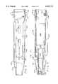
- FIG. 2is a view of the camera taken generally on line 2--2 of FIG. 1, according to another embodiment of the invention.
- FIG. 3is a sectional view of the camera taken generally on line 3--3 of FIG. 2.
- FIG. 4is an enlarged sectional view of the camera showing a collar and lens carrier according to another embodiment of the invention.
- FIG. 5is a top plan view of an embodiment of the camera.
- FIG. 6is a sectional view taken generally on line 6--6 of FIG. 2.
- FIG. 7is a sectional view taken generally on line 7--7 of FIG. 2.
- the inventionprovides for a focus mechanism that can be actuated at the proximal end of a handheld camera, with the image sensor being stationary and the lens element being movable to achieve focus.
- the inventionis particularly useful with intraoral (dental) cameras having a handpiece whose distal end is inserted into a patient's mouth.
- FIG. 1illustrates an embodiment of the invention as a camera 100.
- the camerahas a distal end 134 and proximal end 132 being at opposite ends of an outer casing 142.
- An actuator used for focusingcomprising a ring 116 in this embodiment is provided near the proximal end.
- FIGS. 2 and 3show a perspective view and a side sectional view of an embodiment of the camera 100.
- the camera 100has a body 102 with a cavity 106 formed therein between the distal end 134 and the proximal end 132.
- An image sensor 104is fixed in a stationary manner to the body 102.
- the image sensorin one embodiment, is particularly suitable for intraoral imaging, such as one based on charge coupled device (CCD) technology.
- a cable assembly 105electrically connects the sensor 104 to an interface at the proximal end 132. The interface is used to communicate with an image processing system 101.
- CCDcharge coupled device
- the camera 100may be equipped with a light source near the distal end 134 to illuminate the subject during imaging.
- this light sourceis obtained using an optical fiber 164 used as a light transmission medium to channel light generated beyond the camera 100 to the distal end of the camera and out onto the subject (not shown).
- the cavity 106extends to the distal end 134 of the camera forming an opening for light reflected from a subject to enter the body 102. Light reflected from the subject enters through the prism 162 and is further guided onto an optional relay lens 129 and through to a lens element 128.
- the lens element 128is movably disposed in the cavity 106 for focusing light onto the image sensor 104.
- the lens element 128is coupled to a drive 108.
- the drive 108forms part of a cam together with the ring 116.
- the ring 116is fixed near the proximal end 132 in a direction parallel to a longitudinal axis of the body 102, between a portion of the outer casing 142 and a dress nut 115. Rotation of the ring 116 around the axis translates into linear motion of the drive 108 by way of a pin 117 engaging and pushing against a cam slot 119 in the drive 108.
- Focusingis thus achieved by moving the actuator, e.g., rotating the ring, which causes linear movement of the lens element 128 with respect to the stationary image sensor 104.
- Alternatives to the rotatable ring 116may be a rotatable wheel or other suitable actuator such as a motor driven assembly.
- An alternative to the rotatable mechanism forming a cam with the drive 108may be a lever having linear movement and featuring some gain such that the lever has greater travel than the drive.
- the body 102is made of several sections that are attached together during assembly of the camera 100.
- a head body 103houses the image sensor 104, cable assembly 105, and the interface 107.
- a cylindrical lens tube 112is connected to the head body 103, where the cavity 106 extends into both the head body 103 and the lens tube 112.
- a carrier 120is movably disposed in the lens tube 112, the carrier holding the lens element 128.
- the carrier 120is sized to slidably fit inside the lens tube 112.
- the carrier 120is coupled to the drive 108 through a longitudinal slot 109 in the lens tube 112.
- the coupling between the carrier 120 and the drive 108may be accomplished by means of a collar 124 that is movably engaging an outer surface of the lens tube 112 and is coupled to the drive 108.
- the collar 124is coupled to the carrier 120 by means of a fastener 139 through the slot 109 in the lens tube 112.
- the fastenermay be a set screw.
- the set screwhas a top portion which is threaded into a corresponding hole in the collar 124 while the collar is aligned with the slot 109 and the carrier 120 inside the lens tube.
- the bottom portion of the set screwis not threaded and engages a corresponding hole in the carrier 120.
- Means other than the above for coupling the collar lens element 128 to the drivemay be used such as a direct pin from the drive to either the carrier 120 or the lens element 128 itself.
- FIG. 7illustrates a sectional view taken generally on line 7--7 of FIG. 2.
- the cavity 106can be seen inside the cylindrical lens tube 112 having the slot 109 and containing the carrier 120.
- the collar 124is shown with the fastener 139 coupling the carrier 120 to the collar 124.
- the collar 124is in turn coupled to the drive 108 via two screws.
- the drive 108 in this embodimentis a thin arcuate piece. However, alternatives may be a flat piece that slides against a corresponding flat section of the head body 103.
- the camera 100may house one of a combination of different optics.
- such opticscan be configured for intraoral imaging.
- the opticsmay include a relay lens 129 that works in conjunction with the movable lens elements 127 and 128.
- the relay lensmay be eliminated in favor of a direct optical system.
- the right angle prism 162 and a micro lens 146may be attached to the distal 134 to further enhance performance for intraoral imaging.
- the drive 108is a thin piece that can slide against a corresponding surface of the body 102, and in particular the head body 103.
- the drive 108can be slidably moved in a direction parallel to the common longitudinal axis of the lens tube 112 and the head body 103, and may be guided by posts 107 on the head body 103.
- the drivehas a cam slot 109 that is engaged by a pin 117 connected to the inside surface of the ring 116.
- the drive 108 and the ring 116are located such that the drive 108 extends past the image sensor 104 before being coupled to the collar 124.
- the image sensor 104is fixed at a stationary location between the ring 116 and the movable lens element 128.
- the cam slot 119may have either a fixed profile or variable profile as shown in FIGS. 2 and 5.
- the variable profileallows two ratios of rotational movement of the ring 116 to linear movement of the drive 108.
- the variable profile of FIG. 5can be used to obtain three focus regions, one for capturing fine detail of the subject (e.g., detail of intraoral tissue), one for normal image detail corresponding to the pin 117 located at the boundary between the different profiles (e.g., teeth and gums), and one for capturing images of subjects that are farther away (e.g., the mouth and face of a patient taken with the distal end 134 of the camera 100 outside of the patient's mouth).
- the variable profilemay be selected to allow the same amount of rotational movement on either side of a center of position of the ring 116 to correspond to different optical distances covered by the moving lens element 128.
- a detent mechanismsuch as the one illustrated in FIG. 6 can also be provided.
- FIG. 6shows a sectional view taken generally on line 6--6 of FIG. 2, and shows a spring loaded ball bearing 148 provided in the head body 103.
- a corresponding detent slot 155 in the ring 116is designed to receive the ball of the bearing 148 at the center position of the ring 116, giving the user a tactile sense of a mid-range focus when the pin 117 is located in the boundary between the different profiles of the cam slot 119.
- the head body 103can be made of an engineering plastic such as ERTALYTE or a fiberglass filled nylon material.
- the drive 108may be made of stainless steel, or other high strength material in view of the relatively thin cross-section of the drive.
- the lens tube 112, collar 124, and carrier 120may be made of aluminum, and sized so that the collar 124 slides easily against the outer surface of the lens tube 112 and the carrier 120 slides easily against the inside surface of the lens tube 112.
- a cam mechanismtranslates rotational movement of a ring around an image sensor into linear movement of one or more lens elements in front of the image sensor, the image sensor being stationary. Keeping the image sensor stationary helps increase system reliability due to less stress being placed on the electrical connections to the image sensor.
- the embodiments of the invention describedare of course, subject to some variations in structure or use.
- the head body 103being cylindrical in cross section, other shapes may be used that still have the cavity 106 and support the drive 108.
- the position of the ring near the proximal end of the cameraallows the user to easily focus the camera, where the camera may be held by one hand of a user and focused with the user's other hand. Alternatively, the camera may be held and focused with the same hand. In both instances, the focusing hand is advantageously kept away from the patient's mouth when the distal end of the camera is inserted into the patient's mouth.
- the embodiments described aboveare merely designed to illustrate the invention and should not be construed to limit the scope of the invention which is determined by the claims and their legal equivalents.
Landscapes
- Health & Medical Sciences (AREA)
- Life Sciences & Earth Sciences (AREA)
- Surgery (AREA)
- General Health & Medical Sciences (AREA)
- Medical Informatics (AREA)
- Veterinary Medicine (AREA)
- Pathology (AREA)
- Public Health (AREA)
- Biophysics (AREA)
- Engineering & Computer Science (AREA)
- Biomedical Technology (AREA)
- Heart & Thoracic Surgery (AREA)
- Physics & Mathematics (AREA)
- Molecular Biology (AREA)
- Animal Behavior & Ethology (AREA)
- Nuclear Medicine, Radiotherapy & Molecular Imaging (AREA)
- Radiology & Medical Imaging (AREA)
- Optics & Photonics (AREA)
- Dentistry (AREA)
- Oral & Maxillofacial Surgery (AREA)
- Audiology, Speech & Language Pathology (AREA)
- Endoscopes (AREA)
- Instruments For Viewing The Inside Of Hollow Bodies (AREA)
Abstract
Description
1. Field of the Invention
This invention is generally related to electronic cameras and more specifically to focusing mechanisms in electronic handheld cameras configured with intraoral imaging optics.
2. Description of Related Art
Electronic handheld cameras configured with intraoral imaging optics ("intraoral cameras") are used for capturing images of the inside of a patient's mouth. The camera typically has an elongated body that contains an image sensor and optics. The optics and the sensor are designed for capturing images of the inside of the mouth when the distal end of the camera is inserted into the patient's mouth. Wires carrying electronic signals typically connect the image sensor to the proximal end of the camera where a communication interface is provided to an image processing system or monitor that allows manipulation and display of the images.
Several types of focus mechanisms for the intraoral camera have been developed. One type has a rotatable dial located at approximately half-way between the proximal and distal ends. Focusing is accomplished by rotating the dial which translates into linear motion of a focusing lens with respect to a stationary image sensor. The focusing lens is positioned between the image sensor and optical elements near the distal end. Locating the dial in the middle of the camera, however, places the user's hand too close to the patient's mouth when focusing.
An alternative technique for an intraoral camera places the focus dial farther away from the distal end, at the proximal end of the camera. In that case, rotation of the dial moves the image sensor relative to the optics to achieve focus. Although in that case the dial is conveniently located far from the distal end of the camera which is inserted into the patient's mouth, long term use by repeated focusing might result in the failure of the wire connection between the image sensor and the proximal end of the camera.
Therefore, a novel intraoral camera is needed which permits a more reliable electrical connection to the image sensor while at the same time allowing the user to focus with her hand away from the patient's mouth and preferably at the rear of the camera.
Accordingly, one embodiment of the invention is directed at a camera handpiece having a body with a proximal end and a distal end, and a cavity formed therein. The distal end has an opening for light to enter the cavity. An image sensor is stationary and located inside the cavity to receive the light. An actuator is coupled to the body and positioned near the proximal end. A drive is coupled to the actuator. A lens element is coupled to the drive and movably disposed in the cavity for focusing the light onto the image sensor in response to movement of the actuator.
FIG. 1 is a perspective view of a camera according to an embodiment of the invention.
FIG. 2 is a view of the camera taken generally online 2--2 of FIG. 1, according to another embodiment of the invention.
FIG. 3 is a sectional view of the camera taken generally on line 3--3 of FIG. 2.
FIG. 4 is an enlarged sectional view of the camera showing a collar and lens carrier according to another embodiment of the invention.
FIG. 5 is a top plan view of an embodiment of the camera.
FIG. 6 is a sectional view taken generally on line 6--6 of FIG. 2.
FIG. 7 is a sectional view taken generally on line 7--7 of FIG. 2.
As briefly summarized above, the invention provides for a focus mechanism that can be actuated at the proximal end of a handheld camera, with the image sensor being stationary and the lens element being movable to achieve focus. The invention is particularly useful with intraoral (dental) cameras having a handpiece whose distal end is inserted into a patient's mouth.
FIG. 1 illustrates an embodiment of the invention as a camera 100. The camera has a distal end 134 and proximal end 132 being at opposite ends of anouter casing 142. An actuator used for focusing comprising aring 116 in this embodiment is provided near the proximal end. FIGS. 2 and 3 show a perspective view and a side sectional view of an embodiment of the camera 100. The camera 100 has a body 102 with acavity 106 formed therein between the distal end 134 and the proximal end 132. Animage sensor 104 is fixed in a stationary manner to the body 102. The image sensor, in one embodiment, is particularly suitable for intraoral imaging, such as one based on charge coupled device (CCD) technology. A cable assembly 105 electrically connects thesensor 104 to an interface at the proximal end 132. The interface is used to communicate with an image processing system 101.
The camera 100 may be equipped with a light source near the distal end 134 to illuminate the subject during imaging. In the particular embodiment of FIG. 3, this light source is obtained using an optical fiber 164 used as a light transmission medium to channel light generated beyond the camera 100 to the distal end of the camera and out onto the subject (not shown). Thecavity 106 extends to the distal end 134 of the camera forming an opening for light reflected from a subject to enter the body 102. Light reflected from the subject enters through the prism 162 and is further guided onto an optional relay lens 129 and through to alens element 128.
Thelens element 128 is movably disposed in thecavity 106 for focusing light onto theimage sensor 104. Thelens element 128 is coupled to adrive 108. In one embodiment, thedrive 108 forms part of a cam together with thering 116. Thering 116 is fixed near the proximal end 132 in a direction parallel to a longitudinal axis of the body 102, between a portion of theouter casing 142 and adress nut 115. Rotation of thering 116 around the axis translates into linear motion of thedrive 108 by way of a pin 117 engaging and pushing against acam slot 119 in thedrive 108. Focusing is thus achieved by moving the actuator, e.g., rotating the ring, which causes linear movement of thelens element 128 with respect to thestationary image sensor 104. Alternatives to therotatable ring 116 may be a rotatable wheel or other suitable actuator such as a motor driven assembly. An alternative to the rotatable mechanism forming a cam with thedrive 108 may be a lever having linear movement and featuring some gain such that the lever has greater travel than the drive.
In the particular embodiments illustrated herein, the body 102 is made of several sections that are attached together during assembly of the camera 100. Ahead body 103 houses theimage sensor 104, cable assembly 105, and theinterface 107. Acylindrical lens tube 112 is connected to thehead body 103, where thecavity 106 extends into both thehead body 103 and thelens tube 112. Acarrier 120 is movably disposed in thelens tube 112, the carrier holding thelens element 128. Thecarrier 120 is sized to slidably fit inside thelens tube 112. Thecarrier 120 is coupled to thedrive 108 through alongitudinal slot 109 in thelens tube 112.
Referring now to FIGS. 4 and 7, the coupling between thecarrier 120 and thedrive 108 may be accomplished by means of acollar 124 that is movably engaging an outer surface of thelens tube 112 and is coupled to thedrive 108. Thecollar 124 is coupled to thecarrier 120 by means of afastener 139 through theslot 109 in thelens tube 112. In one embodiment, the fastener may be a set screw. The set screw has a top portion which is threaded into a corresponding hole in thecollar 124 while the collar is aligned with theslot 109 and thecarrier 120 inside the lens tube. The bottom portion of the set screw is not threaded and engages a corresponding hole in thecarrier 120. Means other than the above for coupling thecollar lens element 128 to the drive may be used such as a direct pin from the drive to either thecarrier 120 or thelens element 128 itself.
FIG. 7 illustrates a sectional view taken generally on line 7--7 of FIG. 2. Thecavity 106 can be seen inside thecylindrical lens tube 112 having theslot 109 and containing thecarrier 120. Thecollar 124 is shown with thefastener 139 coupling thecarrier 120 to thecollar 124. Thecollar 124 is in turn coupled to thedrive 108 via two screws. Thedrive 108 in this embodiment is a thin arcuate piece. However, alternatives may be a flat piece that slides against a corresponding flat section of thehead body 103.
The camera 100 may house one of a combination of different optics. In one embodiment, such optics can be configured for intraoral imaging. As shown in FIG. 3, the optics may include a relay lens 129 that works in conjunction with themovable lens elements
In the embodiment of the invention illustrated in FIGS. 4 and 5, thedrive 108 is a thin piece that can slide against a corresponding surface of the body 102, and in particular thehead body 103. Thedrive 108 can be slidably moved in a direction parallel to the common longitudinal axis of thelens tube 112 and thehead body 103, and may be guided byposts 107 on thehead body 103. The drive has acam slot 109 that is engaged by a pin 117 connected to the inside surface of thering 116. In this embodiment, thedrive 108 and thering 116 are located such that thedrive 108 extends past theimage sensor 104 before being coupled to thecollar 124. Theimage sensor 104 is fixed at a stationary location between thering 116 and themovable lens element 128.
In the embodiments of the invention described above, thecam slot 119 may have either a fixed profile or variable profile as shown in FIGS. 2 and 5. The variable profile allows two ratios of rotational movement of thering 116 to linear movement of thedrive 108. For instance, the variable profile of FIG. 5 can be used to obtain three focus regions, one for capturing fine detail of the subject (e.g., detail of intraoral tissue), one for normal image detail corresponding to the pin 117 located at the boundary between the different profiles (e.g., teeth and gums), and one for capturing images of subjects that are farther away (e.g., the mouth and face of a patient taken with the distal end 134 of the camera 100 outside of the patient's mouth).
The variable profile may be selected to allow the same amount of rotational movement on either side of a center of position of thering 116 to correspond to different optical distances covered by the movinglens element 128. A detent mechanism such as the one illustrated in FIG. 6 can also be provided. FIG. 6 shows a sectional view taken generally on line 6--6 of FIG. 2, and shows a spring loaded ball bearing 148 provided in thehead body 103. A corresponding detent slot 155 in thering 116 is designed to receive the ball of the bearing 148 at the center position of thering 116, giving the user a tactile sense of a mid-range focus when the pin 117 is located in the boundary between the different profiles of thecam slot 119.
A wide range of different materials may be used for the different components of the camera 100 described above. For instance, thehead body 103 can be made of an engineering plastic such as ERTALYTE or a fiberglass filled nylon material. Thedrive 108 may be made of stainless steel, or other high strength material in view of the relatively thin cross-section of the drive. Thelens tube 112,collar 124, andcarrier 120 may be made of aluminum, and sized so that thecollar 124 slides easily against the outer surface of thelens tube 112 and thecarrier 120 slides easily against the inside surface of thelens tube 112.
To summarize, the invention has been illustrated by several embodiments of a handheld camera equipped with a focus actuator conveniently located near its proximal end. In one embodiment, a cam mechanism translates rotational movement of a ring around an image sensor into linear movement of one or more lens elements in front of the image sensor, the image sensor being stationary. Keeping the image sensor stationary helps increase system reliability due to less stress being placed on the electrical connections to the image sensor.
The embodiments of the invention described, are of course, subject to some variations in structure or use. For example, although some of the figures illustrate thehead body 103 being cylindrical in cross section, other shapes may be used that still have thecavity 106 and support thedrive 108. Also, in the intraoral embodiment of the camera, the position of the ring near the proximal end of the camera allows the user to easily focus the camera, where the camera may be held by one hand of a user and focused with the user's other hand. Alternatively, the camera may be held and focused with the same hand. In both instances, the focusing hand is advantageously kept away from the patient's mouth when the distal end of the camera is inserted into the patient's mouth. In general, the embodiments described above are merely designed to illustrate the invention and should not be construed to limit the scope of the invention which is determined by the claims and their legal equivalents.
Claims (17)
1. A camera comprising:
a body having a proximal end, a distal end, and a cavity, the distal end having an opening for light to enter the cavity, the body having a lens portion with a slot therein;
image sensor mounted in a fixed position inside the cavity;
actuator drive coupled to the actuator coupled to the body and positioned near the proximal end;
collar movably engaging an outside surface of the lens portion of the body and coupled to the drive;
carrier movably disposed in the lens portion of the body and coupled to the collar through the slot in the lens portion; and
lens element held by the carrier for focusing light onto the image sensor in response to movement of the actuator.
2. The camera of claim 1 wherein the actuator comprises a ring rotatably coupled to the body, and wherein the drive and the ring form a cam for translating rotational movement of the ring into linear movement of the drive.
3. The camera of claim 2 wherein the drive has a cam slot engaged by a pin connected to the ring.
4. The camera of claim 1 further comprising:
optics disposed near the opening in the distal end, the optics and the lens element being configured for intraoral imaging.
5. The camera of claim 1 wherein the image sensor is located between the actuator and the lens element.
6. The camera of claim 1 wherein the lens portion of the body is cylindrical.
7. A handheld article comprising:
a head body having a proximal end and a cavity, the head body having a cylindrical outside surface;
a cylindrical lens tube coupled to the head body and having a distal end, the distal end having an opening for light to enter the cavity through the tube;
image sensor being stationary inside the cavity;
actuator coupled to the head body near the proximal end;
drive coupled to the actuator and having an arcuate cross-section mated to the outside surface of the head body; and
lens element coupled to the drive and movably disposed in the tube for focusing the light onto the image sensor in response to movement of the actuator.
8. The handheld article of claim 7 wherein the actuator comprises a ring being fixed in a direction parallel to a longitudinal axis of the head body and being rotatable about the axis.
9. The handheld article of claim 7 wherein the lens element is configured for intraoral imaging.
10. A camera comprising:
a body having a proximal end, a distal end, and a cavity, the distal end having an opening for light to enter the cavity;
image sensor mounted in a fixed position inside the cavity;
actuator having a ring rotatably coupled to the body and positioned near the proximal end, the ring having a pin connected thereto;
drive having a cam slot engaged by the pin for translating rotational movement of the ring into linear movement of the drive; and
lens element coupled to the drive and movably disposed in the cavity for focusing light onto the image sensor in response to movement of the actuator.
11. The camera of claim 10 wherein the cam slot has a variable profile shaped to provide at least two different ratios of rotational movement of the ring to linear movement of the drive.
12. The camera of claim 11 wherein the cam slot is shaped to provide different focus travel of the lens element on either side of a center position, for the same amount of rotational movement of the ring in opposite directions.
13. The camera of claim 12 further comprising:
detent for providing a tactile sense of a mid-range focus.
14. The camera of claim 10 wherein the body comprises a cylindrical lens tube portion in which a carrier is movably disposed, the carrier holding the lens element and coupled to the drive through a slot in the lens tube.
15. The camera of claim 14 further comprising:
collar movably engaging an outside surface of the lens tube portion and coupled to the drive, the collar being coupled to the carrier through the slot in the lens tube.
16. The camera of claim 10 further comprising:
optics disposed near the opening in the distal end, the optics and the lens element being configured for intraoral imaging.
17. The camera of claim 10 wherein the image sensor is located between the actuator and the lens element.
Priority Applications (1)
| Application Number | Priority Date | Filing Date | Title |
|---|---|---|---|
| US09/094,234US6019721A (en) | 1998-06-09 | 1998-06-09 | Camera with improved focus mechanism |
Applications Claiming Priority (1)
| Application Number | Priority Date | Filing Date | Title |
|---|---|---|---|
| US09/094,234US6019721A (en) | 1998-06-09 | 1998-06-09 | Camera with improved focus mechanism |
Publications (1)
| Publication Number | Publication Date |
|---|---|
| US6019721Atrue US6019721A (en) | 2000-02-01 |
Family
ID=22243927
Family Applications (1)
| Application Number | Title | Priority Date | Filing Date |
|---|---|---|---|
| US09/094,234Expired - LifetimeUS6019721A (en) | 1998-06-09 | 1998-06-09 | Camera with improved focus mechanism |
Country Status (1)
| Country | Link |
|---|---|
| US (1) | US6019721A (en) |
Cited By (39)
| Publication number | Priority date | Publication date | Assignee | Title |
|---|---|---|---|---|
| US6161035A (en)* | 1997-04-30 | 2000-12-12 | Asahi Kogaku Kogyo Kabushiki Kaisha | Fluorescence diagnostic apparatus |
| US6428471B1 (en)* | 1999-02-03 | 2002-08-06 | William E. Durell, Jr. | Variable view arthroscope |
| USD467660S1 (en) | 2001-11-07 | 2002-12-24 | Cygnus Technologies, L.L.C. | Dental imaging apparatus |
| USD468429S1 (en) | 2001-03-26 | 2003-01-07 | Kaltenbach & Voight Gmbh | Intraoral camera |
| US20030053061A1 (en)* | 1999-12-08 | 2003-03-20 | X-Rite, Incorporated | Optical measurement device and related process |
| US6540668B1 (en)* | 1998-12-21 | 2003-04-01 | Henke-Sass, Wolf Gmbh | Endoscope with a coupling device (video coupler) for connection of a video camera |
| US6572539B2 (en)* | 2000-09-04 | 2003-06-03 | Fuji Photo Optical Co., Ltd. | Linear transmission member driving unit for endoscope |
| US20030142206A1 (en)* | 2002-01-28 | 2003-07-31 | Williams Ronald R. | Cable with built in-frame grabber for a dental video camera |
| US20040253563A1 (en)* | 2003-06-10 | 2004-12-16 | Gregorio John Joseph | Compact digital intraoral camera |
| US20050027169A1 (en)* | 2003-07-28 | 2005-02-03 | Welch Allyn, Inc. | Otoscope |
| US20050143624A1 (en)* | 2003-12-31 | 2005-06-30 | Given Imaging Ltd. | Immobilizable in-vivo imager with moveable focusing mechanism |
| US20060167339A1 (en)* | 2002-12-26 | 2006-07-27 | Zvika Gilad | Immobilizable in vivo sensing device |
| AU2003253676B2 (en)* | 2002-06-10 | 2006-11-09 | Gendex Corporation | Compact digital intraoral camera |
| US20070270651A1 (en)* | 2006-05-19 | 2007-11-22 | Zvika Gilad | Device and method for illuminating an in vivo site |
| US20080051637A1 (en)* | 2003-07-28 | 2008-02-28 | Welch Allyn, Inc. | Digital otoscope |
| US20090281389A1 (en)* | 2004-12-30 | 2009-11-12 | Iddan Gavriel J | Device, system, and method for adaptive imaging |
| US20100137686A1 (en)* | 2002-04-25 | 2010-06-03 | Gavriel Meron | Device and method for orienting a device in vivo |
| US20100137685A1 (en)* | 2008-12-02 | 2010-06-03 | Tokendo | Deviated viewing rigid videoendoscope with adjustable focusing |
| US7753842B2 (en) | 2001-06-28 | 2010-07-13 | Given Imaging Ltd. | In vivo imaging device with a small cross sectional area |
| WO2010094805A1 (en)* | 2009-02-23 | 2010-08-26 | Sirona Dental Systems Gmbh | Handheld dental camera and method for optical 3d measurement |
| US20100238279A1 (en)* | 2007-03-16 | 2010-09-23 | Durr Dental Ag | Diagnostic Camera and Attachment for the Implementation Thereof |
| USD630747S1 (en)* | 2009-10-27 | 2011-01-11 | Panasonic Corporation | Intraoral camera |
| US20110157457A1 (en)* | 2009-12-30 | 2011-06-30 | Carestream Health, Inc. | Auto-focus intra-oral camera having a linear piezoelectric actuator |
| EP2380484A1 (en) | 2010-04-20 | 2011-10-26 | Carestream Health, Inc. | Auto-focus intra-oral camera having a linear piezoelectric actuator |
| EP2452613A1 (en)* | 2010-11-11 | 2012-05-16 | Kaltenbach & Voigt GmbH | Medical, in particular dental, diagnosis device with imaging means |
| USD678525S1 (en)* | 2011-03-16 | 2013-03-19 | Panasonic Corporation | Intraoral camera |
| ITBO20120451A1 (en)* | 2012-08-23 | 2014-02-24 | Cefla Coop | CAMERA FOR MEDICAL USE WITH SELECTION OF DIFFERENT OPERATING MODES |
| US20140276102A1 (en)* | 2013-03-14 | 2014-09-18 | Lumicell, Inc. | Medical imaging device and methods of use |
| US8944596B2 (en) | 2011-11-09 | 2015-02-03 | Welch Allyn, Inc. | Digital-based medical devices |
| USD722164S1 (en)* | 2014-02-13 | 2015-02-03 | 3M Innovative Properties Company | Intra-oral scanning wand |
| US9204788B2 (en) | 2011-03-21 | 2015-12-08 | Carestream Health, Inc. | Autofocus method using liquid lens |
| JP2016010470A (en)* | 2014-06-27 | 2016-01-21 | 株式会社吉田製作所 | probe |
| USD774193S1 (en)* | 2015-08-24 | 2016-12-13 | Align Technology, Inc. | Sleeve for an intraoral scanner |
| USD780182S1 (en)* | 2013-03-11 | 2017-02-28 | D4D Technologies, Llc | Handheld scanner |
| USD813392S1 (en)* | 2016-01-16 | 2018-03-20 | Ping Wang | Dental intraoral camera |
| US10078226B2 (en) | 2013-10-14 | 2018-09-18 | Welch Allyn, Inc. | Portable eye viewing device enabled for enhanced field of view |
| US10111581B2 (en) | 2014-02-27 | 2018-10-30 | Align Technology, Inc. | Thermal defogging system and method |
| US10728519B2 (en) | 2004-06-17 | 2020-07-28 | Align Technology, Inc. | Method and apparatus for colour imaging a three-dimensional structure |
| US11147441B2 (en) | 2018-01-16 | 2021-10-19 | Welch Allyn, Inc. | Physical assessment device |
Citations (19)
| Publication number | Priority date | Publication date | Assignee | Title |
|---|---|---|---|---|
| US4182547A (en)* | 1978-08-10 | 1980-01-08 | American Optical Corporation | Image focusing apparatus for fiberscopes |
| US4558691A (en)* | 1983-08-18 | 1985-12-17 | Olympus Optical Co. Ltd. | Endoscope |
| US4765313A (en)* | 1986-08-01 | 1988-08-23 | Olympus Optical Co., Ltd. | Objective part replaceable endoscope tip |
| US4901144A (en)* | 1988-07-20 | 1990-02-13 | Welch Allyn, Inc. | Video endoscope aperture wheel drive system |
| US4905082A (en)* | 1987-05-06 | 1990-02-27 | Olympus Optical Co., Ltd. | Rigid video endoscope having a detachable imaging unit |
| US4969450A (en)* | 1990-01-25 | 1990-11-13 | Smith & Nephew Dyonics, Inc. | Videoarthroscope with one-handed control |
| US5051824A (en)* | 1989-10-30 | 1991-09-24 | Olympus Optical Co., Ltd. | Electronic scope having detachable frame to which solid state imaging device is fastened |
| US5191879A (en)* | 1991-07-24 | 1993-03-09 | Welch Allyn, Inc. | Variable focus camera for borescope or endoscope |
| US5278642A (en)* | 1992-02-26 | 1994-01-11 | Welch Allyn, Inc. | Color imaging system |
| US5290168A (en)* | 1987-03-05 | 1994-03-01 | Optical Systems, Inc. | Electronic video dental camera |
| US5408992A (en)* | 1993-11-05 | 1995-04-25 | British Technology Group Usa Inc. | Endoscopic device for intraoral use |
| US5487661A (en)* | 1993-10-08 | 1996-01-30 | Dentsply International, Inc. | Portable dental camera and system |
| US5528432A (en)* | 1994-02-23 | 1996-06-18 | Ultrak, Inc. | Intra-oral optical viewing device |
| US5527261A (en)* | 1994-08-18 | 1996-06-18 | Welch Allyn, Inc. | Remote hand-held diagnostic instrument with video imaging |
| US5575757A (en)* | 1992-10-09 | 1996-11-19 | Smith & Nephew Endoscopy Inc. | Endoscope with focusing mechanism |
| US5702349A (en)* | 1994-07-07 | 1997-12-30 | Fuji Photo Optical Co., Ltd. | Endoscope with acutely angled handle and associated focus adjustment mechanism |
| US5737013A (en)* | 1992-09-11 | 1998-04-07 | Williams; Ronald R. | Dental video camera with an adjustable iris |
| US5797836A (en)* | 1995-06-07 | 1998-08-25 | Smith & Nephew, Inc. | Endoscope with relative rotation and axial motion between an optical element and an imaging device |
| US5879289A (en)* | 1996-07-15 | 1999-03-09 | Universal Technologies International, Inc. | Hand-held portable endoscopic camera |
- 1998
- 1998-06-09USUS09/094,234patent/US6019721A/ennot_activeExpired - Lifetime
Patent Citations (20)
| Publication number | Priority date | Publication date | Assignee | Title |
|---|---|---|---|---|
| US4182547A (en)* | 1978-08-10 | 1980-01-08 | American Optical Corporation | Image focusing apparatus for fiberscopes |
| US4558691A (en)* | 1983-08-18 | 1985-12-17 | Olympus Optical Co. Ltd. | Endoscope |
| US4765313A (en)* | 1986-08-01 | 1988-08-23 | Olympus Optical Co., Ltd. | Objective part replaceable endoscope tip |
| US5290168A (en)* | 1987-03-05 | 1994-03-01 | Optical Systems, Inc. | Electronic video dental camera |
| US4905082A (en)* | 1987-05-06 | 1990-02-27 | Olympus Optical Co., Ltd. | Rigid video endoscope having a detachable imaging unit |
| US4901144A (en)* | 1988-07-20 | 1990-02-13 | Welch Allyn, Inc. | Video endoscope aperture wheel drive system |
| US5051824A (en)* | 1989-10-30 | 1991-09-24 | Olympus Optical Co., Ltd. | Electronic scope having detachable frame to which solid state imaging device is fastened |
| US4969450A (en)* | 1990-01-25 | 1990-11-13 | Smith & Nephew Dyonics, Inc. | Videoarthroscope with one-handed control |
| US5191879A (en)* | 1991-07-24 | 1993-03-09 | Welch Allyn, Inc. | Variable focus camera for borescope or endoscope |
| US5278642A (en)* | 1992-02-26 | 1994-01-11 | Welch Allyn, Inc. | Color imaging system |
| US5737013A (en)* | 1992-09-11 | 1998-04-07 | Williams; Ronald R. | Dental video camera with an adjustable iris |
| US5575757A (en)* | 1992-10-09 | 1996-11-19 | Smith & Nephew Endoscopy Inc. | Endoscope with focusing mechanism |
| US5487661A (en)* | 1993-10-08 | 1996-01-30 | Dentsply International, Inc. | Portable dental camera and system |
| US5836762A (en)* | 1993-10-08 | 1998-11-17 | Dentsply International Inc. | Portable dental camera system and method |
| US5408992A (en)* | 1993-11-05 | 1995-04-25 | British Technology Group Usa Inc. | Endoscopic device for intraoral use |
| US5528432A (en)* | 1994-02-23 | 1996-06-18 | Ultrak, Inc. | Intra-oral optical viewing device |
| US5702349A (en)* | 1994-07-07 | 1997-12-30 | Fuji Photo Optical Co., Ltd. | Endoscope with acutely angled handle and associated focus adjustment mechanism |
| US5527261A (en)* | 1994-08-18 | 1996-06-18 | Welch Allyn, Inc. | Remote hand-held diagnostic instrument with video imaging |
| US5797836A (en)* | 1995-06-07 | 1998-08-25 | Smith & Nephew, Inc. | Endoscope with relative rotation and axial motion between an optical element and an imaging device |
| US5879289A (en)* | 1996-07-15 | 1999-03-09 | Universal Technologies International, Inc. | Hand-held portable endoscopic camera |
Cited By (72)
| Publication number | Priority date | Publication date | Assignee | Title |
|---|---|---|---|---|
| US6161035A (en)* | 1997-04-30 | 2000-12-12 | Asahi Kogaku Kogyo Kabushiki Kaisha | Fluorescence diagnostic apparatus |
| US6540668B1 (en)* | 1998-12-21 | 2003-04-01 | Henke-Sass, Wolf Gmbh | Endoscope with a coupling device (video coupler) for connection of a video camera |
| US6428471B1 (en)* | 1999-02-03 | 2002-08-06 | William E. Durell, Jr. | Variable view arthroscope |
| US6750971B2 (en) | 1999-12-08 | 2004-06-15 | X-Rite, Incorporated | Optical measurement device and related process |
| US20030053061A1 (en)* | 1999-12-08 | 2003-03-20 | X-Rite, Incorporated | Optical measurement device and related process |
| US7050168B2 (en) | 1999-12-08 | 2006-05-23 | X-Rite, Incorporated | Optical measurement device and related process |
| US7030986B2 (en) | 1999-12-08 | 2006-04-18 | X-Rite Incorporated | Optical measurement device and related process |
| US6867864B2 (en) | 1999-12-08 | 2005-03-15 | X-Rite, Incorporated | Optical measurement device and related process |
| US20050122518A1 (en)* | 1999-12-08 | 2005-06-09 | Overbeck James L. | Optical measurement device and related process |
| US6572539B2 (en)* | 2000-09-04 | 2003-06-03 | Fuji Photo Optical Co., Ltd. | Linear transmission member driving unit for endoscope |
| USD468429S1 (en) | 2001-03-26 | 2003-01-07 | Kaltenbach & Voight Gmbh | Intraoral camera |
| US7753842B2 (en) | 2001-06-28 | 2010-07-13 | Given Imaging Ltd. | In vivo imaging device with a small cross sectional area |
| USD467660S1 (en) | 2001-11-07 | 2002-12-24 | Cygnus Technologies, L.L.C. | Dental imaging apparatus |
| US20030142206A1 (en)* | 2002-01-28 | 2003-07-31 | Williams Ronald R. | Cable with built in-frame grabber for a dental video camera |
| US7084899B2 (en)* | 2002-01-28 | 2006-08-01 | Williams Ronald R | Cable with built in-frame grabber for a dental video camera |
| US20100137686A1 (en)* | 2002-04-25 | 2010-06-03 | Gavriel Meron | Device and method for orienting a device in vivo |
| AU2003253676B2 (en)* | 2002-06-10 | 2006-11-09 | Gendex Corporation | Compact digital intraoral camera |
| US7946979B2 (en) | 2002-12-26 | 2011-05-24 | Given Imaging, Ltd. | Immobilizable in vivo sensing device |
| US20060167339A1 (en)* | 2002-12-26 | 2006-07-27 | Zvika Gilad | Immobilizable in vivo sensing device |
| US20040253563A1 (en)* | 2003-06-10 | 2004-12-16 | Gregorio John Joseph | Compact digital intraoral camera |
| US7086859B2 (en)* | 2003-06-10 | 2006-08-08 | Gendex Corporation | Compact digital intraoral camera system |
| US8066634B2 (en) | 2003-07-28 | 2011-11-29 | Welch Allyn, Inc. | Digital otoscope |
| US20080051637A1 (en)* | 2003-07-28 | 2008-02-28 | Welch Allyn, Inc. | Digital otoscope |
| US7399275B2 (en)* | 2003-07-28 | 2008-07-15 | Welch Allyn, Inc. | Otoscope |
| AU2004261180B2 (en)* | 2003-07-28 | 2009-09-03 | Welch Allyn, Inc. | Otoscope |
| US10470650B2 (en) | 2003-07-28 | 2019-11-12 | Welch Allyn, Inc. | Digital otoscope |
| US10966600B2 (en) | 2003-07-28 | 2021-04-06 | Welch Allyn, Inc. | Digital otoscope |
| US11805990B2 (en) | 2003-07-28 | 2023-11-07 | Welch Allyn, Inc. | Digital otoscope |
| US11071446B2 (en) | 2003-07-28 | 2021-07-27 | Welch Allyn, Inc. | Digital otoscope |
| US20050027169A1 (en)* | 2003-07-28 | 2005-02-03 | Welch Allyn, Inc. | Otoscope |
| US20050143624A1 (en)* | 2003-12-31 | 2005-06-30 | Given Imaging Ltd. | Immobilizable in-vivo imager with moveable focusing mechanism |
| US8702597B2 (en)* | 2003-12-31 | 2014-04-22 | Given Imaging Ltd. | Immobilizable in-vivo imager with moveable focusing mechanism |
| US10750151B2 (en) | 2004-06-17 | 2020-08-18 | Align Technology, Inc. | Method and apparatus for colour imaging a three-dimensional structure |
| US10944953B2 (en) | 2004-06-17 | 2021-03-09 | Align Technology, Inc. | Method and apparatus for colour imaging a three-dimensional structure |
| US10924720B2 (en) | 2004-06-17 | 2021-02-16 | Align Technology, Inc. | Systems and methods for determining surface topology and associated color of an intraoral structure |
| US10812773B2 (en) | 2004-06-17 | 2020-10-20 | Align Technology, Inc. | Method and apparatus for colour imaging a three-dimensional structure |
| US10764557B2 (en) | 2004-06-17 | 2020-09-01 | Align Technology, Inc. | Method and apparatus for imaging a three-dimensional structure |
| US10728519B2 (en) | 2004-06-17 | 2020-07-28 | Align Technology, Inc. | Method and apparatus for colour imaging a three-dimensional structure |
| US10750152B2 (en) | 2004-06-17 | 2020-08-18 | Align Technology, Inc. | Method and apparatus for structure imaging a three-dimensional structure |
| US20090281389A1 (en)* | 2004-12-30 | 2009-11-12 | Iddan Gavriel J | Device, system, and method for adaptive imaging |
| US20070270651A1 (en)* | 2006-05-19 | 2007-11-22 | Zvika Gilad | Device and method for illuminating an in vivo site |
| US20100238279A1 (en)* | 2007-03-16 | 2010-09-23 | Durr Dental Ag | Diagnostic Camera and Attachment for the Implementation Thereof |
| US20100137685A1 (en)* | 2008-12-02 | 2010-06-03 | Tokendo | Deviated viewing rigid videoendoscope with adjustable focusing |
| US8577212B2 (en) | 2009-02-23 | 2013-11-05 | Sirona Dental Systems Gmbh | Handheld dental camera and method for carrying out optical 3D measurement |
| WO2010094805A1 (en)* | 2009-02-23 | 2010-08-26 | Sirona Dental Systems Gmbh | Handheld dental camera and method for optical 3d measurement |
| USD630747S1 (en)* | 2009-10-27 | 2011-01-11 | Panasonic Corporation | Intraoral camera |
| US8305486B2 (en) | 2009-12-30 | 2012-11-06 | Carestream Health, Inc. | Auto-focus intra-oral camera having a linear piezoelectric actuator |
| US20110157457A1 (en)* | 2009-12-30 | 2011-06-30 | Carestream Health, Inc. | Auto-focus intra-oral camera having a linear piezoelectric actuator |
| EP2380484A1 (en) | 2010-04-20 | 2011-10-26 | Carestream Health, Inc. | Auto-focus intra-oral camera having a linear piezoelectric actuator |
| EP2452613A1 (en)* | 2010-11-11 | 2012-05-16 | Kaltenbach & Voigt GmbH | Medical, in particular dental, diagnosis device with imaging means |
| USD678525S1 (en)* | 2011-03-16 | 2013-03-19 | Panasonic Corporation | Intraoral camera |
| US9204788B2 (en) | 2011-03-21 | 2015-12-08 | Carestream Health, Inc. | Autofocus method using liquid lens |
| US10238462B2 (en) | 2011-11-09 | 2019-03-26 | Welch Allyn, Inc. | Digital-based medical devices |
| US8944596B2 (en) | 2011-11-09 | 2015-02-03 | Welch Allyn, Inc. | Digital-based medical devices |
| US11553981B2 (en) | 2011-11-09 | 2023-01-17 | Welch Allyn, Inc. | Digital-based medical devices |
| US9642517B2 (en) | 2011-11-09 | 2017-05-09 | Welch Allyn, Inc. | Digital-based medical devices |
| ITBO20120451A1 (en)* | 2012-08-23 | 2014-02-24 | Cefla Coop | CAMERA FOR MEDICAL USE WITH SELECTION OF DIFFERENT OPERATING MODES |
| US9510741B2 (en) | 2012-08-23 | 2016-12-06 | Cefla Societá Cooperativa | Medical camera with selection of different working modes |
| EP2700350A1 (en)* | 2012-08-23 | 2014-02-26 | Cefla Societa' Cooperativa | Medical camera with selection of different working modes |
| USD780182S1 (en)* | 2013-03-11 | 2017-02-28 | D4D Technologies, Llc | Handheld scanner |
| US10791937B2 (en)* | 2013-03-14 | 2020-10-06 | Lumicell, Inc. | Medical imaging device and methods of use |
| US20140276102A1 (en)* | 2013-03-14 | 2014-09-18 | Lumicell, Inc. | Medical imaging device and methods of use |
| US10078226B2 (en) | 2013-10-14 | 2018-09-18 | Welch Allyn, Inc. | Portable eye viewing device enabled for enhanced field of view |
| USD722164S1 (en)* | 2014-02-13 | 2015-02-03 | 3M Innovative Properties Company | Intra-oral scanning wand |
| US11134834B2 (en) | 2014-02-27 | 2021-10-05 | Alighn Technology, Inc. | Protective sleeve for intraoral scanner |
| US10111581B2 (en) | 2014-02-27 | 2018-10-30 | Align Technology, Inc. | Thermal defogging system and method |
| JP2016010470A (en)* | 2014-06-27 | 2016-01-21 | 株式会社吉田製作所 | probe |
| USD774193S1 (en)* | 2015-08-24 | 2016-12-13 | Align Technology, Inc. | Sleeve for an intraoral scanner |
| USD806248S1 (en) | 2015-08-24 | 2017-12-26 | Align Technology, Inc. | Sleeve for an intraoral scanner |
| USD813392S1 (en)* | 2016-01-16 | 2018-03-20 | Ping Wang | Dental intraoral camera |
| US11147441B2 (en) | 2018-01-16 | 2021-10-19 | Welch Allyn, Inc. | Physical assessment device |
| USD959661S1 (en) | 2018-01-16 | 2022-08-02 | Welch Allyn, Inc. | Medical viewing device |
Similar Documents
| Publication | Publication Date | Title |
|---|---|---|
| US6019721A (en) | Camera with improved focus mechanism | |
| US6641530B2 (en) | Endoscope with objective lens drive mechanism | |
| US5582576A (en) | Electronic endoscope with zoom lens system | |
| US6958766B2 (en) | Dental video imaging system | |
| JPH1156754A (en) | Operation unit of endoscope | |
| US6409658B1 (en) | Endoscope with objective lens drive mechanism | |
| JPWO2011027594A1 (en) | Imaging unit | |
| CA2107872A1 (en) | Focusing Endoscope | |
| US20020135694A1 (en) | Dental video camera | |
| EP1372461B1 (en) | Dental video imaging system | |
| JP4172845B2 (en) | Zoom endoscope | |
| JP3360799B2 (en) | Endoscope objective drive mechanism | |
| JP4185316B2 (en) | Endoscope actuator support structure | |
| JP2929471B2 (en) | Endoscope device | |
| JPH02181718A (en) | Electronic endoscope | |
| JPH1142202A (en) | Endoscope objective drive mechanism | |
| JP2002209831A (en) | Endoscope | |
| JP4390354B2 (en) | Endoscope objective drive mechanism | |
| JP4103217B2 (en) | Endoscope with objective lens moving mechanism | |
| JP3380141B2 (en) | Endoscope objective drive mechanism | |
| JPH04335611A (en) | Fitting structure for solid-state image pickup device for electronic endoscope | |
| JP4426054B2 (en) | Endoscope objective drive mechanism | |
| JP2002301015A (en) | Electronic endoscope for magnifying observation | |
| JPH063495B2 (en) | Endoscope | |
| WO2002082820A1 (en) | Dental video imaging system |
Legal Events
| Date | Code | Title | Description |
|---|---|---|---|
| AS | Assignment | Owner name:INTEGRA MEDICAL, CALIFORNIA Free format text:ASSIGNMENT OF ASSIGNORS INTEREST;ASSIGNORS:HOLMES, DAVID P.;GOLAY, DOUGLAS A.;REEL/FRAME:009243/0492;SIGNING DATES FROM 19980528 TO 19980608 | |
| STCF | Information on status: patent grant | Free format text:PATENTED CASE | |
| FPAY | Fee payment | Year of fee payment:4 | |
| AS | Assignment | Owner name:HENRY SCHEIN, INC., NEW YORK Free format text:ASSIGNMENT OF ASSIGNORS INTEREST;ASSIGNOR:INTEGRA MEDICAL INC.;REEL/FRAME:017931/0208 Effective date:20060706 | |
| AS | Assignment | Owner name:DEXIS, LLC, ILLINOIS Free format text:ASSIGNMENT OF ASSIGNORS INTEREST;ASSIGNOR:HENRY SCHEIN, INC.;REEL/FRAME:018700/0091 Effective date:20061227 | |
| FPAY | Fee payment | Year of fee payment:8 | |
| FPAY | Fee payment | Year of fee payment:12 |