US6019481A - Light fixture with recessed electrical outlet, data receptacle, and support frame for mounting on a wall - Google Patents
Light fixture with recessed electrical outlet, data receptacle, and support frame for mounting on a wallDownload PDFInfo
- Publication number
- US6019481A US6019481AUS09/018,663US1866398AUS6019481AUS 6019481 AUS6019481 AUS 6019481AUS 1866398 AUS1866398 AUS 1866398AUS 6019481 AUS6019481 AUS 6019481A
- Authority
- US
- United States
- Prior art keywords
- support frame
- opening
- housing portion
- light fixture
- outlet
- Prior art date
- Legal status (The legal status is an assumption and is not a legal conclusion. Google has not performed a legal analysis and makes no representation as to the accuracy of the status listed.)
- Expired - Lifetime
Links
Images

Classifications
- F—MECHANICAL ENGINEERING; LIGHTING; HEATING; WEAPONS; BLASTING
- F21—LIGHTING
- F21S—NON-PORTABLE LIGHTING DEVICES; SYSTEMS THEREOF; VEHICLE LIGHTING DEVICES SPECIALLY ADAPTED FOR VEHICLE EXTERIORS
- F21S8/00—Lighting devices intended for fixed installation
- F21S8/03—Lighting devices intended for fixed installation of surface-mounted type
- F21S8/033—Lighting devices intended for fixed installation of surface-mounted type the surface being a wall or like vertical structure, e.g. building facade
- F—MECHANICAL ENGINEERING; LIGHTING; HEATING; WEAPONS; BLASTING
- F21—LIGHTING
- F21S—NON-PORTABLE LIGHTING DEVICES; SYSTEMS THEREOF; VEHICLE LIGHTING DEVICES SPECIALLY ADAPTED FOR VEHICLE EXTERIORS
- F21S2/00—Systems of lighting devices, not provided for in main groups F21S4/00 - F21S10/00 or F21S19/00, e.g. of modular construction
- F—MECHANICAL ENGINEERING; LIGHTING; HEATING; WEAPONS; BLASTING
- F21—LIGHTING
- F21V—FUNCTIONAL FEATURES OR DETAILS OF LIGHTING DEVICES OR SYSTEMS THEREOF; STRUCTURAL COMBINATIONS OF LIGHTING DEVICES WITH OTHER ARTICLES, NOT OTHERWISE PROVIDED FOR
- F21V21/00—Supporting, suspending, or attaching arrangements for lighting devices; Hand grips
- F21V21/02—Wall, ceiling, or floor bases; Fixing pendants or arms to the bases
- F—MECHANICAL ENGINEERING; LIGHTING; HEATING; WEAPONS; BLASTING
- F21—LIGHTING
- F21V—FUNCTIONAL FEATURES OR DETAILS OF LIGHTING DEVICES OR SYSTEMS THEREOF; STRUCTURAL COMBINATIONS OF LIGHTING DEVICES WITH OTHER ARTICLES, NOT OTHERWISE PROVIDED FOR
- F21V33/00—Structural combinations of lighting devices with other articles, not otherwise provided for
- F21V33/0064—Health, life-saving or fire-fighting equipment
- F21V33/0068—Medical equipment
- F21V33/0072—Hospital beds
- F—MECHANICAL ENGINEERING; LIGHTING; HEATING; WEAPONS; BLASTING
- F21—LIGHTING
- F21V—FUNCTIONAL FEATURES OR DETAILS OF LIGHTING DEVICES OR SYSTEMS THEREOF; STRUCTURAL COMBINATIONS OF LIGHTING DEVICES WITH OTHER ARTICLES, NOT OTHERWISE PROVIDED FOR
- F21V17/00—Fastening of component parts of lighting devices, e.g. shades, globes, refractors, reflectors, filters, screens, grids or protective cages
- F21V17/10—Fastening of component parts of lighting devices, e.g. shades, globes, refractors, reflectors, filters, screens, grids or protective cages characterised by specific fastening means or way of fastening
- F21V17/107—Fastening of component parts of lighting devices, e.g. shades, globes, refractors, reflectors, filters, screens, grids or protective cages characterised by specific fastening means or way of fastening using hinge joints
- F—MECHANICAL ENGINEERING; LIGHTING; HEATING; WEAPONS; BLASTING
- F21—LIGHTING
- F21V—FUNCTIONAL FEATURES OR DETAILS OF LIGHTING DEVICES OR SYSTEMS THEREOF; STRUCTURAL COMBINATIONS OF LIGHTING DEVICES WITH OTHER ARTICLES, NOT OTHERWISE PROVIDED FOR
- F21V25/00—Safety devices structurally associated with lighting devices
- F21V25/02—Safety devices structurally associated with lighting devices coming into action when lighting device is disturbed, dismounted, or broken
- F21V25/04—Safety devices structurally associated with lighting devices coming into action when lighting device is disturbed, dismounted, or broken breaking the electric circuit
- F—MECHANICAL ENGINEERING; LIGHTING; HEATING; WEAPONS; BLASTING
- F21—LIGHTING
- F21W—INDEXING SCHEME ASSOCIATED WITH SUBCLASSES F21K, F21L, F21S and F21V, RELATING TO USES OR APPLICATIONS OF LIGHTING DEVICES OR SYSTEMS
- F21W2131/00—Use or application of lighting devices or systems not provided for in codes F21W2102/00-F21W2121/00
- F21W2131/20—Lighting for medical use
- F21W2131/208—Lighting for medical use for hospital wards
- F—MECHANICAL ENGINEERING; LIGHTING; HEATING; WEAPONS; BLASTING
- F21—LIGHTING
- F21Y—INDEXING SCHEME ASSOCIATED WITH SUBCLASSES F21K, F21L, F21S and F21V, RELATING TO THE FORM OR THE KIND OF THE LIGHT SOURCES OR OF THE COLOUR OF THE LIGHT EMITTED
- F21Y2103/00—Elongate light sources, e.g. fluorescent tubes
- F—MECHANICAL ENGINEERING; LIGHTING; HEATING; WEAPONS; BLASTING
- F21—LIGHTING
- F21Y—INDEXING SCHEME ASSOCIATED WITH SUBCLASSES F21K, F21L, F21S and F21V, RELATING TO THE FORM OR THE KIND OF THE LIGHT SOURCES OR OF THE COLOUR OF THE LIGHT EMITTED
- F21Y2115/00—Light-generating elements of semiconductor light sources
- F21Y2115/10—Light-emitting diodes [LED]
- Y—GENERAL TAGGING OF NEW TECHNOLOGICAL DEVELOPMENTS; GENERAL TAGGING OF CROSS-SECTIONAL TECHNOLOGIES SPANNING OVER SEVERAL SECTIONS OF THE IPC; TECHNICAL SUBJECTS COVERED BY FORMER USPC CROSS-REFERENCE ART COLLECTIONS [XRACs] AND DIGESTS
- Y10—TECHNICAL SUBJECTS COVERED BY FORMER USPC
- Y10S—TECHNICAL SUBJECTS COVERED BY FORMER USPC CROSS-REFERENCE ART COLLECTIONS [XRACs] AND DIGESTS
- Y10S362/00—Illumination
- Y10S362/801—Bedroom lighting, e.g. modular combinations
Definitions
- the present inventionrelates to a light fixture apparatus for mounting on a wall of a room, such as in a hospital room. More particularly, the present invention relates to a light fixture apparatus which facilitates mounting of accessory items to the wall and connection to electrical power to facilitate equipment management within the hospital room.
- Some conventional hospital roomsare provided with a track mounted on a wall of the hospital room. When the track is installed, back plating must be added behind the wall in order to support devices such as accessory items coupled to the track.
- the trackincludes an electrical raceway for providing power to the track. Light fixtures or other devices are then mounted on the track in a desired position.
- the light fixture apparatus of the present inventionis designed to support heavy devices such as a patient monitor arm which can weigh 80 pounds or more.
- the light fixture apparatus of the present inventiondoes not require back plating to be installed behind the wall. This facilitates installation of the light fixture apparatus.
- the customersimply installs the light fixture apparatus of the present invention by anchoring the light fixture to studs of the wall. The customer then can install a monitor arm, or any other designed accessories onto a track formed on the light fixture without doing any further construction to the wall.
- the present inventionalso includes an accessory mounting block which is easily installed onto and released from the track on the light fixture to support smaller accessory items.
- the light fixture apparatus of the present inventionincluding a support frame configured to be mounted to a wall and a light box coupled to the support frame.
- a hollow housing portionis also coupled to the support and frame alongside the light box.
- An openingis provided in the housing and a horizontal electrical outlet is in the housing portion opposite the opening.
- the housing portionincludes a first cover pivotally coupled to the support frame at a first end and spaced from the support frame at a second end to form the opening.
- a second coveris secured in the housing to enclose the wiring of the electrical outlet.
- a horizontal data or communication receptacleis also provided in the housing opposite the opening. While the support frame, preferably, is made from extruded metal material, the hollow housing is made from sheet metal.
- FIG. 1is a perspective view of the light fixture apparatus of the present invention with a monitor arm attached to a track on the light fixture.
- FIG. 2is a perspective view similar to the FIG. 1 in which a central auxiliary light has been flipped over.
- FIG. 3is a sectional view taken through the light fixture apparatus of FIG. 1 illustrating a reinforced support member and a first mounting bracket assembly for securing a heavy piece of equipment such as the monitor arm to the light fixture apparatus.
- FIG. 4is a perspective view of an end-portion with the cover open showing the electrical outlets incorporating the principles of the present invention.
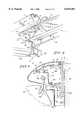
- FIG. 5is a cross-sectional view taken along lines VV of FIG. 4 with the cover in its down position.
- FIGS. 1 and 2illustrate a light fixture apparatus 10 of the present invention.
- the light fixture 10includes a central light box 12 for holding a light source therein.
- the light fixture 10also includes hollow end portions 14 and 16 on opposite sides of the light box.
- a flip-out auxiliary light source 18is located above light box 12.
- the auxiliary light source 18is pivotable in the directions of double-headed arrow 20 to direct the auxiliary light source 22 toward a patient, such as during an exam.
- Handles 24are provided on opposite ends of the auxiliary light 18.
- Light fixture 10further includes an accessory track 26 for mounting accessory items onto the light fixture 10.
- a monitor arm 28can be coupled to the track 26 with a fastener assembly 30 best disclosed in FIG. 3.
- a monitor 32is cantilevered from the track 26 by the monitor arm 28 and fastener assembly 30.
- Light fixture 10is designed to be mounted directly to studs of a wall 46. In most instances, the light fixture 10 permits mounting of accessory items such as the monitor 32 onto track 26 without the use of back plating behind the wall. This facilitates installation of the light fixture 10.
- Light fixture 10includes a reinforced support frame 34 having a first support member 36 and a second support member 38.
- first support member 36is formed from an extruded metal material, such as aluminum for strength.
- First support 36includes a pair of parallel support walls 40 and 42 interconnected by webs 44. Therefore, the first support provides a reinforced support assembly for the light fixture 10.
- the first support member 36is coupled directly to studs in a wall 46 to secure the light fixture 10 to the wall 46. In most instances, back plating is not required for the light fixture 10 due to the reinforced support 34.
- the second support member 38is preferably made from sheet metal and has a first, vertically extending section 48 and a second, generally horizontally extending section 50. Second support member 38 is coupled to the first support member 36 by suitable fasteners 52. An interior region 54 is defined between the first support 36 and the second support member 38 for receiving components such as a ballast 56.
- the auxiliary light source 18includes a housing 58 defining an interior region 60 for holding the auxiliary light source 62.
- the auxiliary light source 62is a halogen lamp.
- a front wall 64 of housing 58is coupled to horizontal leg 50 of second support 38 by hinges 66.
- the first side of each hinge 66is coupled to the wall 64 by a fastener 68.
- a second side of each hinge 66is coupled to horizontal leg 50 by fastener 70.
- An internal sheet metal cover 72is provided for protecting and shielding internal parts of the light fixture 10 when the auxiliary light 18 is flipped to its open position illustrated in FIG. 2.
- a fastener 73secures the cover 72 to the first support member 36.
- Light box 12is coupled to horizontal leg 50 by fasteners 74 and 76. Fasteners permit limited movement of the light box 12 relative to horizontal leg 50 in the directions of double-headed arrow 78.
- a switch 80is also coupled to horizontal leg 50. Switch 80 includes a plunger 82 configured to deactivate the bed when plunger 82 is engaged. In other words, if an item makes contact with light box 12 and pushes the light box 12 upwardly toward horizontal leg 50, a top surface 84 of light box 12 engages plunger 82 to deactivate movement of the bed. The obstruction must be cleared to release the plunger 82 in order to restore power to move the bed.
- FIG. 3also illustrates further details of the mounting track 26 and the fastener assembly 30.
- the mounting track 26is a generally S-shaped track including a first, upper stop 88 and a second, lower stop 90.
- a recessed portion 92 of track 26provides room for a fastener 94.
- Fastener assembly 30includes a S-shaped mounting block 96 configured to be coupled to a desired item such as bracket 98 of monitor arm 28 by the fastener 94.
- An HPL laminate facia insert 99is coupled to first support member 36 adjacent track 26.
- a top end 100 of mounting block 96is configured to abut the first stop 88 on support 36.
- Mounting bracket 98is also secured to a second mounting block 102 by fastener 104.
- Mounting block 102is formed to include a top flange 106 configured to engage the second stop 90 of the support member 36.
- a bottom end 108 of mounting block 96is trapped between support member 36 and mounting block 102.
- FIGS. 4 and 5illustrate the configuration of the hollow end portions 14 and 16 of the light fixture 10.
- a movable cover 110is coupled to support 36 by a hinge 112.
- a first fastener 114secures the hinge 112 to the first support member 36.
- the second support member 38has a first vertically extending portion 48, a second generally horizontally extending section 50 and a third vertically extending section 51.
- the second support member 38is coupled to the first support member 36 by the fasteners 52.
- Mounted in openings in the horizontal portion 50 of the second support member 38is a duplex electrical outlet 116.
- a plug 118 from the monitor 28is plugged into the horizontal electrical outlet 116.
- the wire 120extends through the gap or opening 122 between the cover 110 and the first support member 36 and the second support member 38.
- a horizontal outletallows for ease of insertion removal and further reduces the strain on the plug 118 and the wire 120.
- the opening 122 between the cover 110 and the support members 36 and 38is sufficiently small to minimize removal of the plug 118 without rotating the cover 110 about hinge 112.
- the size of the opening 122also minimizes contact of the outlet 116 by individuals and thereby reducing the risk of electrocution as well as damaging the outlet or a communication or data jack.
- the space 54 between the first support 36 and second support 38is enclosed by cover 72 secured to the first support 36 by fastener 73 and to vertical wall 51 of support 36 by fastener 71. This provides an enclosed cable housing or duct.
- a data or communication jack or receptacle 126is also provided in the vertical wall 50 of the second support 38. This allows connection of the monitor or other equipment to a communication bus.
- cover 110is preferably shown as a single unit, the two-piece cover 110 with living hinge of the previously mentioned patent application may also be used although not preferred.
- the pivoting of the cover 110 about pivot 112provides not only access to the outlet 116 and the jack 120, but also allows movement of the cover 110 if force is applied thereto by, for example, an I.V. pole or other equipment within the room related to the patient.
Landscapes
- Engineering & Computer Science (AREA)
- General Engineering & Computer Science (AREA)
- Health & Medical Sciences (AREA)
- Biomedical Technology (AREA)
- Architecture (AREA)
- Accommodation For Nursing Or Treatment Tables (AREA)
- Arrangement Of Elements, Cooling, Sealing, Or The Like Of Lighting Devices (AREA)
- Non-Portable Lighting Devices Or Systems Thereof (AREA)
Abstract
Description
Claims (12)
Priority Applications (6)
| Application Number | Priority Date | Filing Date | Title |
|---|---|---|---|
| US09/018,663US6019481A (en) | 1996-08-29 | 1998-02-04 | Light fixture with recessed electrical outlet, data receptacle, and support frame for mounting on a wall |
| AU23404/99AAU2340499A (en) | 1998-02-04 | 1999-01-26 | Light fixture with electrical outlets |
| EP99903362AEP1053432A1 (en) | 1998-02-04 | 1999-01-26 | Light fixture with electrical outlets |
| JP2000530738AJP2003511814A (en) | 1998-02-04 | 1999-01-26 | Lighting equipment with electric outlet |
| CA002319518ACA2319518A1 (en) | 1998-02-04 | 1999-01-26 | Light fixture with electrical outlets |
| PCT/US1999/001529WO1999040363A1 (en) | 1998-02-04 | 1999-01-26 | Light fixture with electrical outlets |
Applications Claiming Priority (2)
| Application Number | Priority Date | Filing Date | Title |
|---|---|---|---|
| US08/705,214US5735593A (en) | 1996-08-29 | 1996-08-29 | Light fixture apparatus for a hospital room |
| US09/018,663US6019481A (en) | 1996-08-29 | 1998-02-04 | Light fixture with recessed electrical outlet, data receptacle, and support frame for mounting on a wall |
Related Parent Applications (1)
| Application Number | Title | Priority Date | Filing Date |
|---|---|---|---|
| US08/705,214Continuation-In-PartUS5735593A (en) | 1996-08-29 | 1996-08-29 | Light fixture apparatus for a hospital room |
Publications (1)
| Publication Number | Publication Date |
|---|---|
| US6019481Atrue US6019481A (en) | 2000-02-01 |
Family
ID=21789137
Family Applications (1)
| Application Number | Title | Priority Date | Filing Date |
|---|---|---|---|
| US09/018,663Expired - LifetimeUS6019481A (en) | 1996-08-29 | 1998-02-04 | Light fixture with recessed electrical outlet, data receptacle, and support frame for mounting on a wall |
Country Status (6)
| Country | Link |
|---|---|
| US (1) | US6019481A (en) |
| EP (1) | EP1053432A1 (en) |
| JP (1) | JP2003511814A (en) |
| AU (1) | AU2340499A (en) |
| CA (1) | CA2319518A1 (en) |
| WO (1) | WO1999040363A1 (en) |
Cited By (13)
| Publication number | Priority date | Publication date | Assignee | Title |
|---|---|---|---|---|
| USD456784S1 (en) | 1999-09-21 | 2002-05-07 | Trilux-Lenze Gmbh & Co. Kg. | Supply unit |
| US20030197614A1 (en)* | 2002-04-18 | 2003-10-23 | Bed-Check Corporation | Apparatus for lighting a patient monitor front panel |
| US6932488B1 (en) | 2004-03-02 | 2005-08-23 | Dualume Cabinets, Inc. | Vanity lighting system |
| US7081007B1 (en) | 2005-02-28 | 2006-07-25 | Marchese Christopher L | Ceiling mount electrical fixture |
| US20060260443A1 (en)* | 2003-11-26 | 2006-11-23 | Faries Durward I Jr | Fastening system and method of fastening objects with enhanced security |
| US7198513B2 (en) | 2005-02-28 | 2007-04-03 | Marchese Christopher L | Ceiling mount electrical fixture |
| US20070126318A1 (en)* | 2004-10-14 | 2007-06-07 | Hamberg Stephen R | Service head with accessory tracks |
| US20070267209A1 (en)* | 2006-05-19 | 2007-11-22 | Lifespan Healthcare, Llc | Component-based utility supply apparatus |
| US20100246194A1 (en)* | 2009-03-27 | 2010-09-30 | Nankil Robert R | Lighting fixture having a latching system and an auxiliary emergency light |
| US20100259915A1 (en)* | 2009-04-14 | 2010-10-14 | Irma Hubbs | Window light box with blind |
| US8333038B2 (en) | 2010-02-11 | 2012-12-18 | Herman Miller, Inc. | Wall mounted assembly |
| US8458962B2 (en) | 1999-04-22 | 2013-06-11 | Hill-Rom Services, Inc. | Wall unit having concealable service outlets |
| WO2014108440A1 (en)* | 2013-01-08 | 2014-07-17 | Zumtobel Lighting Gmbh | Hospital supply device with patient reading light |
Citations (25)
| Publication number | Priority date | Publication date | Assignee | Title |
|---|---|---|---|---|
| US2215531A (en)* | 1939-07-14 | 1940-09-24 | Alphonse F Pieper | Lighting unit |
| US2998508A (en)* | 1959-05-19 | 1961-08-29 | Sunbeam Lighting Company | Hospital service console and bedlight fixture combination |
| US3007038A (en)* | 1959-09-04 | 1961-10-31 | Richard C Anisfield | Hospital type wall lamps |
| US3084247A (en)* | 1961-07-03 | 1963-04-02 | Sunbeam Lighting Company | Wall mounted hospital bed light fixture and service console combination |
| US3201582A (en)* | 1963-07-03 | 1965-08-17 | Al L Siegel | Two-way hospital light |
| US3354301A (en)* | 1967-02-09 | 1967-11-21 | Bobrick Mitchell | Room utility and service system |
| FR1554391A (en)* | 1967-02-20 | 1969-01-17 | ||
| US3462892A (en)* | 1968-01-22 | 1969-08-26 | Ronald K Meyer | Adapter wall |
| US3567842A (en)* | 1968-09-05 | 1971-03-02 | Ronald K Meyer | Wall structure |
| US3660591A (en)* | 1970-10-26 | 1972-05-02 | Hill Rom Co Inc | Hospital in-patient service core module |
| US3702928A (en)* | 1971-03-22 | 1972-11-14 | David W Alger | Adjustable lighting apparatus |
| US3769502A (en)* | 1970-10-26 | 1973-10-30 | Hill Rom Co Inc | Hospital service unit |
| US3919540A (en)* | 1974-04-11 | 1975-11-11 | Hill Rom Co Inc | Safety light |
| US4104710A (en)* | 1977-05-31 | 1978-08-01 | Joerns Furniture Company, Division Of American Seating Company | Patient headwall unit |
| US4204274A (en)* | 1977-06-25 | 1980-05-20 | Willi Luderitz | Wall light fixture, particularly for hospital rooms |
| US4589557A (en)* | 1983-07-09 | 1986-05-20 | Bollmann Armin A | Mounting means for (releasably and movably) mounting devices on a wall, particularly in clinics, first aid or surgery rooms, and the like; and manufacturing method for said mounting means |
| DE3506030A1 (en)* | 1985-02-21 | 1986-08-21 | Trilux-Lenze Gmbh + Co Kg, 5760 Arnsberg | Sick-room wall lighting fitting |
| US4646211A (en)* | 1984-11-19 | 1987-02-24 | Hill-Rom Company, Inc. | Service outlet wall and rail system for use thereon |
| US4651258A (en)* | 1986-03-06 | 1987-03-17 | Professional Medical Products, Inc. | Retractable light assembly |
| US4816969A (en)* | 1988-02-05 | 1989-03-28 | Hospital Systems Inc. | Wall-mounted over-bed lighting fixture |
| US4891897A (en)* | 1985-12-12 | 1990-01-09 | Gieske Detlef J | Display panel |
| US5272608A (en)* | 1992-09-21 | 1993-12-21 | Alkco Manufacturing Company | Hospital room lamp |
| US5277005A (en)* | 1992-05-04 | 1994-01-11 | Teknion Furniture Systems | Free-standing partitioning panel |
| DE29717690U1 (en)* | 1997-10-04 | 1997-11-13 | DZ-Licht Außenleuchten GmbH & Co KG, 58730 Fröndenberg | Recessed floor light |
| US5735593A (en)* | 1996-08-29 | 1998-04-07 | Hill-Rom, Inc. | Light fixture apparatus for a hospital room |
Family Cites Families (1)
| Publication number | Priority date | Publication date | Assignee | Title |
|---|---|---|---|---|
| AT297846B (en)* | 1970-09-25 | 1972-04-10 | Siemens Ag | Wall lamp for hospital rooms |
- 1998
- 1998-02-04USUS09/018,663patent/US6019481A/ennot_activeExpired - Lifetime
- 1999
- 1999-01-26WOPCT/US1999/001529patent/WO1999040363A1/ennot_activeApplication Discontinuation
- 1999-01-26CACA002319518Apatent/CA2319518A1/ennot_activeAbandoned
- 1999-01-26EPEP99903362Apatent/EP1053432A1/ennot_activeWithdrawn
- 1999-01-26JPJP2000530738Apatent/JP2003511814A/enactivePending
- 1999-01-26AUAU23404/99Apatent/AU2340499A/ennot_activeAbandoned
Patent Citations (25)
| Publication number | Priority date | Publication date | Assignee | Title |
|---|---|---|---|---|
| US2215531A (en)* | 1939-07-14 | 1940-09-24 | Alphonse F Pieper | Lighting unit |
| US2998508A (en)* | 1959-05-19 | 1961-08-29 | Sunbeam Lighting Company | Hospital service console and bedlight fixture combination |
| US3007038A (en)* | 1959-09-04 | 1961-10-31 | Richard C Anisfield | Hospital type wall lamps |
| US3084247A (en)* | 1961-07-03 | 1963-04-02 | Sunbeam Lighting Company | Wall mounted hospital bed light fixture and service console combination |
| US3201582A (en)* | 1963-07-03 | 1965-08-17 | Al L Siegel | Two-way hospital light |
| US3354301A (en)* | 1967-02-09 | 1967-11-21 | Bobrick Mitchell | Room utility and service system |
| FR1554391A (en)* | 1967-02-20 | 1969-01-17 | ||
| US3462892A (en)* | 1968-01-22 | 1969-08-26 | Ronald K Meyer | Adapter wall |
| US3567842A (en)* | 1968-09-05 | 1971-03-02 | Ronald K Meyer | Wall structure |
| US3660591A (en)* | 1970-10-26 | 1972-05-02 | Hill Rom Co Inc | Hospital in-patient service core module |
| US3769502A (en)* | 1970-10-26 | 1973-10-30 | Hill Rom Co Inc | Hospital service unit |
| US3702928A (en)* | 1971-03-22 | 1972-11-14 | David W Alger | Adjustable lighting apparatus |
| US3919540A (en)* | 1974-04-11 | 1975-11-11 | Hill Rom Co Inc | Safety light |
| US4104710A (en)* | 1977-05-31 | 1978-08-01 | Joerns Furniture Company, Division Of American Seating Company | Patient headwall unit |
| US4204274A (en)* | 1977-06-25 | 1980-05-20 | Willi Luderitz | Wall light fixture, particularly for hospital rooms |
| US4589557A (en)* | 1983-07-09 | 1986-05-20 | Bollmann Armin A | Mounting means for (releasably and movably) mounting devices on a wall, particularly in clinics, first aid or surgery rooms, and the like; and manufacturing method for said mounting means |
| US4646211A (en)* | 1984-11-19 | 1987-02-24 | Hill-Rom Company, Inc. | Service outlet wall and rail system for use thereon |
| DE3506030A1 (en)* | 1985-02-21 | 1986-08-21 | Trilux-Lenze Gmbh + Co Kg, 5760 Arnsberg | Sick-room wall lighting fitting |
| US4891897A (en)* | 1985-12-12 | 1990-01-09 | Gieske Detlef J | Display panel |
| US4651258A (en)* | 1986-03-06 | 1987-03-17 | Professional Medical Products, Inc. | Retractable light assembly |
| US4816969A (en)* | 1988-02-05 | 1989-03-28 | Hospital Systems Inc. | Wall-mounted over-bed lighting fixture |
| US5277005A (en)* | 1992-05-04 | 1994-01-11 | Teknion Furniture Systems | Free-standing partitioning panel |
| US5272608A (en)* | 1992-09-21 | 1993-12-21 | Alkco Manufacturing Company | Hospital room lamp |
| US5735593A (en)* | 1996-08-29 | 1998-04-07 | Hill-Rom, Inc. | Light fixture apparatus for a hospital room |
| DE29717690U1 (en)* | 1997-10-04 | 1997-11-13 | DZ-Licht Außenleuchten GmbH & Co KG, 58730 Fröndenberg | Recessed floor light |
Non-Patent Citations (2)
| Title |
|---|
| The Horizon Headwall System from Hill Rom , 1994.* |
| The Horizon Headwall System from Hill-Rom, 1994. |
Cited By (23)
| Publication number | Priority date | Publication date | Assignee | Title |
|---|---|---|---|---|
| US8458962B2 (en) | 1999-04-22 | 2013-06-11 | Hill-Rom Services, Inc. | Wall unit having concealable service outlets |
| USD456784S1 (en) | 1999-09-21 | 2002-05-07 | Trilux-Lenze Gmbh & Co. Kg. | Supply unit |
| US20030197614A1 (en)* | 2002-04-18 | 2003-10-23 | Bed-Check Corporation | Apparatus for lighting a patient monitor front panel |
| US6864795B2 (en) | 2002-04-18 | 2005-03-08 | Bed-Check Corporation | Apparatus for lighting a patient monitor front panel |
| US20060260443A1 (en)* | 2003-11-26 | 2006-11-23 | Faries Durward I Jr | Fastening system and method of fastening objects with enhanced security |
| US6932488B1 (en) | 2004-03-02 | 2005-08-23 | Dualume Cabinets, Inc. | Vanity lighting system |
| US20050195593A1 (en)* | 2004-03-02 | 2005-09-08 | Horn Donald N | Vanity lighting system |
| US20070126318A1 (en)* | 2004-10-14 | 2007-06-07 | Hamberg Stephen R | Service head with accessory tracks |
| US7081007B1 (en) | 2005-02-28 | 2006-07-25 | Marchese Christopher L | Ceiling mount electrical fixture |
| US7198513B2 (en) | 2005-02-28 | 2007-04-03 | Marchese Christopher L | Ceiling mount electrical fixture |
| US20070267219A1 (en)* | 2006-05-19 | 2007-11-22 | Lifespan Healthcare, Llc | Component-based utility supply apparatus |
| US7770934B2 (en) | 2006-05-19 | 2010-08-10 | Lifespan Healthcare, Llc | Component-based utility supply apparatus |
| US7857354B2 (en) | 2006-05-19 | 2010-12-28 | Lifespan Healthcare, Llc, A Florida Limited Liability Company | Component-based utility supply apparatus |
| US20070267209A1 (en)* | 2006-05-19 | 2007-11-22 | Lifespan Healthcare, Llc | Component-based utility supply apparatus |
| US20100246194A1 (en)* | 2009-03-27 | 2010-09-30 | Nankil Robert R | Lighting fixture having a latching system and an auxiliary emergency light |
| US7993039B2 (en) | 2009-03-27 | 2011-08-09 | Hubbell Incorporated | Lighting fixture having a latching system and an auxiliary emergency light |
| US20100259915A1 (en)* | 2009-04-14 | 2010-10-14 | Irma Hubbs | Window light box with blind |
| US7887213B2 (en) | 2009-04-14 | 2011-02-15 | Irma Hubbs | Window light box with blind |
| US8333038B2 (en) | 2010-02-11 | 2012-12-18 | Herman Miller, Inc. | Wall mounted assembly |
| US8667742B2 (en) | 2010-02-11 | 2014-03-11 | Herman Miller, Inc. | Wall mounted assembly |
| US9072381B2 (en) | 2010-02-11 | 2015-07-07 | Herman Miller, Inc. | Wall mounted assembly |
| US9635941B2 (en) | 2010-02-11 | 2017-05-02 | Herman Miller, Inc. | Wall mounted assembly |
| WO2014108440A1 (en)* | 2013-01-08 | 2014-07-17 | Zumtobel Lighting Gmbh | Hospital supply device with patient reading light |
Also Published As
| Publication number | Publication date |
|---|---|
| JP2003511814A (en) | 2003-03-25 |
| EP1053432A1 (en) | 2000-11-22 |
| CA2319518A1 (en) | 1999-08-12 |
| WO1999040363A1 (en) | 1999-08-12 |
| AU2340499A (en) | 1999-08-23 |
Similar Documents
| Publication | Publication Date | Title |
|---|---|---|
| US6019481A (en) | Light fixture with recessed electrical outlet, data receptacle, and support frame for mounting on a wall | |
| US6669041B2 (en) | Telecommunication and electrical service box for mounting in a floor | |
| CA2242215C (en) | Fully adjustable electrical receptacle housing | |
| US4338485A (en) | Headwall unit for patient servicing and method for installation | |
| US5913787A (en) | Communications conduit connector mounting device | |
| US6158180A (en) | Mounting device for communications conduit connector | |
| US4403278A (en) | Mounting system for suspended lighting fixtures | |
| US6193341B1 (en) | Tiltable electronics cabinet | |
| US6329591B2 (en) | Wall panel assembly | |
| CA1232668A (en) | Housing for electrical connectors | |
| US6290375B1 (en) | Ballast housing having pivotally engaging mounting means | |
| US5735593A (en) | Light fixture apparatus for a hospital room | |
| US6082031A (en) | Canopy mounting device for exit sign | |
| EP0227434A2 (en) | Electrical services pole | |
| US4922668A (en) | Service access unit for floors | |
| US5013873A (en) | Wireway for enclosing electrical conductors | |
| WO2003069887A2 (en) | Television monitor with ceiling and wall mounting system | |
| JPH11346834A (en) | Wiring duct device for desk | |
| JP2002305835A (en) | Wiring duct | |
| JP3344326B2 (en) | Wiring device stand | |
| AU705694B2 (en) | Cord orifice for flush-mounted electrical outlets | |
| JP2566735Y2 (en) | Partition outlet device | |
| JPS6326056Y2 (en) | ||
| JP3306324B2 (en) | Partition | |
| JPH029718Y2 (en) |
Legal Events
| Date | Code | Title | Description |
|---|---|---|---|
| AS | Assignment | Owner name:HILL-ROM, INC., INDIANA Free format text:ASSIGNMENT OF ASSIGNORS INTEREST;ASSIGNORS:AMBACH, DOUGLAS C.;NOBBE, DALE A.;REEL/FRAME:008971/0106;SIGNING DATES FROM 19980128 TO 19980202 | |
| STCF | Information on status: patent grant | Free format text:PATENTED CASE | |
| AS | Assignment | Owner name:HILL-ROM SERVICES, INC., INDIANA Free format text:ASSIGNMENT OF ASSIGNORS INTEREST;ASSIGNOR:HILL-ROM, INC.;REEL/FRAME:011796/0440 Effective date:20010215 | |
| FPAY | Fee payment | Year of fee payment:4 | |
| FEPP | Fee payment procedure | Free format text:PAYOR NUMBER ASSIGNED (ORIGINAL EVENT CODE: ASPN); ENTITY STATUS OF PATENT OWNER: LARGE ENTITY | |
| FPAY | Fee payment | Year of fee payment:8 | |
| FPAY | Fee payment | Year of fee payment:12 | |
| AS | Assignment | Owner name:JPMORGAN CHASE BANK, N.A., AS COLLATERAL AGENT, ILLINOIS Free format text:SECURITY INTEREST;ASSIGNORS:ALLEN MEDICAL SYSTEMS, INC.;HILL-ROM SERVICES, INC.;ASPEN SURGICAL PRODUCTS, INC.;AND OTHERS;REEL/FRAME:036582/0123 Effective date:20150908 Owner name:JPMORGAN CHASE BANK, N.A., AS COLLATERAL AGENT, IL Free format text:SECURITY INTEREST;ASSIGNORS:ALLEN MEDICAL SYSTEMS, INC.;HILL-ROM SERVICES, INC.;ASPEN SURGICAL PRODUCTS, INC.;AND OTHERS;REEL/FRAME:036582/0123 Effective date:20150908 | |
| AS | Assignment | Owner name:MORTARA INSTRUMENT, INC., WISCONSIN Free format text:RELEASE BY SECURED PARTY;ASSIGNOR:JPMORGAN CHASE BANK, N.A.;REEL/FRAME:050254/0513 Effective date:20190830 Owner name:ANODYNE MEDICAL DEVICE, INC., FLORIDA Free format text:RELEASE BY SECURED PARTY;ASSIGNOR:JPMORGAN CHASE BANK, N.A.;REEL/FRAME:050254/0513 Effective date:20190830 Owner name:HILL-ROM SERVICES, INC., ILLINOIS Free format text:RELEASE BY SECURED PARTY;ASSIGNOR:JPMORGAN CHASE BANK, N.A.;REEL/FRAME:050254/0513 Effective date:20190830 Owner name:VOALTE, INC., FLORIDA Free format text:RELEASE BY SECURED PARTY;ASSIGNOR:JPMORGAN CHASE BANK, N.A.;REEL/FRAME:050254/0513 Effective date:20190830 Owner name:MORTARA INSTRUMENT SERVICES, INC., WISCONSIN Free format text:RELEASE BY SECURED PARTY;ASSIGNOR:JPMORGAN CHASE BANK, N.A.;REEL/FRAME:050254/0513 Effective date:20190830 Owner name:HILL-ROM, INC., ILLINOIS Free format text:RELEASE BY SECURED PARTY;ASSIGNOR:JPMORGAN CHASE BANK, N.A.;REEL/FRAME:050254/0513 Effective date:20190830 Owner name:ALLEN MEDICAL SYSTEMS, INC., ILLINOIS Free format text:RELEASE BY SECURED PARTY;ASSIGNOR:JPMORGAN CHASE BANK, N.A.;REEL/FRAME:050254/0513 Effective date:20190830 Owner name:HILL-ROM COMPANY, INC., ILLINOIS Free format text:RELEASE BY SECURED PARTY;ASSIGNOR:JPMORGAN CHASE BANK, N.A.;REEL/FRAME:050254/0513 Effective date:20190830 Owner name:WELCH ALLYN, INC., NEW YORK Free format text:RELEASE BY SECURED PARTY;ASSIGNOR:JPMORGAN CHASE BANK, N.A.;REEL/FRAME:050254/0513 Effective date:20190830 |