US6018891A - Shoe construction - Google Patents
Shoe constructionDownload PDFInfo
- Publication number
- US6018891A US6018891AUS09/162,163US16216398AUS6018891AUS 6018891 AUS6018891 AUS 6018891AUS 16216398 AUS16216398 AUS 16216398AUS 6018891 AUS6018891 AUS 6018891A
- Authority
- US
- United States
- Prior art keywords
- molded
- shoe
- cup
- molded cup
- outwardly extending
- Prior art date
- Legal status (The legal status is an assumption and is not a legal conclusion. Google has not performed a legal analysis and makes no representation as to the accuracy of the status listed.)
- Expired - Lifetime
Links
- 238000010276constructionMethods0.000titleabstractdescription12
- 230000002045lasting effectEffects0.000claimsabstractdescription18
- 239000000463materialSubstances0.000claimsdescription10
- 239000007924injectionSubstances0.000claimsdescription3
- 238000002347injectionMethods0.000claimsdescription3
- 239000004033plasticSubstances0.000claimsdescription3
- 229920001169thermoplasticPolymers0.000claimsdescription2
- 229920002725thermoplastic elastomerPolymers0.000claims2
- 101100441413Caenorhabditis elegans cup-15 geneProteins0.000description19
- 210000002683footAnatomy0.000description7
- 239000004568cementSubstances0.000description3
- 238000004519manufacturing processMethods0.000description3
- 239000004744fabricSubstances0.000description2
- 210000003423ankleAnatomy0.000description1
- 230000000694effectsEffects0.000description1
- 239000011094fiberboardSubstances0.000description1
- 239000010985leatherSubstances0.000description1
- 238000012986modificationMethods0.000description1
- 230000004048modificationEffects0.000description1
- 239000004416thermosoftening plasticSubstances0.000description1
Images

Classifications
- A—HUMAN NECESSITIES
- A43—FOOTWEAR
- A43B—CHARACTERISTIC FEATURES OF FOOTWEAR; PARTS OF FOOTWEAR
- A43B3/00—Footwear characterised by the shape or the use
- A43B3/14—Moccasins, opanken, or like shoes
- A—HUMAN NECESSITIES
- A43—FOOTWEAR
- A43B—CHARACTERISTIC FEATURES OF FOOTWEAR; PARTS OF FOOTWEAR
- A43B23/00—Uppers; Boot legs; Stiffeners; Other single parts of footwear
- A43B23/08—Heel stiffeners; Toe stiffeners
- A43B23/16—Heel stiffeners; Toe stiffeners made of impregnated fabrics, plastics or the like
- A43B23/17—Heel stiffeners; Toe stiffeners made of impregnated fabrics, plastics or the like made of plastics
- A—HUMAN NECESSITIES
- A43—FOOTWEAR
- A43B—CHARACTERISTIC FEATURES OF FOOTWEAR; PARTS OF FOOTWEAR
- A43B5/00—Footwear for sporting purposes
- A43B5/06—Running shoes; Track shoes
- A—HUMAN NECESSITIES
- A43—FOOTWEAR
- A43B—CHARACTERISTIC FEATURES OF FOOTWEAR; PARTS OF FOOTWEAR
- A43B9/00—Footwear characterised by the assembling of the individual parts
Definitions
- This inventionrelates to shoes, more particularly to shoes with a rigid back part for stability and a flexible front part for comfort.
- U.S. Pat. Nos. 4,852,275 (the '275 patent) and 4,704,808 (the '808 patent)disclose a shoe with a heel counter having an outwardly extending flange to increase stability and resistance to roll over.
- the construction disclosed in the '275 and '808 patentsrequires the rearpart of the upper to be stitched through the outwardly extending flange to a sole component, such as the insole. While this type of construction adds stability to the rear part of the shoe, it also increases the cost to manufacture the shoe.
- the outwardly extending flangeneeds to be located at the interface between the insole and the outwardly extending flange, thereby limiting the design possibilities for shoes utilizing this construction.
- the present inventionprovides improved lateral stability by providing a molded cup, wherein the wearer's foot rests, with a flange extending outwardly from a top edge of the molded cup.
- This outwardly extending flangeincreases the stability of a shoe because it is located a vertical distance above the bottom of the wearer's foot.
- a lasting margin of the upper of the shoeis wrapped around the outwardly extending flange of the molded cup. This provides additional stability by unifying the pliable material of the upper with the stiffer material of the molded cup.
- the location of the outwardly extending flange in relation to the shoecan be varied.
- the moldcan be made deeper such that the outwardly extending flange is located higher in the shoe. This variability allows for different aesthetic designs for different shoe models.
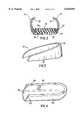
- FIG. 1is a perspective view of a walking shoe constructed in accordance with the invention presently disclosed;
- FIG. 2is a fragmentary cross-sectional view of the front portion of the shoe taken along section line 2--2 of FIG. 1;
- FIG. 3is a perspective view of a heel counter
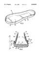
- FIG. 4is a perspective view of a molded heel cup
- FIG. 5is a perspective view an alternative embodiment of the molded heel cup
- FIG. 6is a fragmentary cross-sectional view of the back part of the shoe taken along section line 6--6 of FIG. 1;
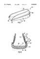
- FIG. 7is a perspective view of an alternative embodiment of a molded heel cup.
- FIG. 8is a fragmentary cross-sectional view of the back part of the shoe with the alternative embodiment of the molded heel cup.
- Shoe 10includes an upper 12, a sole 14, a molded cup 15 (shown in phantom in FIG. 1), and a heel counter 17 (shown in phantom in FIG. 1).
- Upper 12has a vamp 20, medial and lateral quarter panels 21, and foxing 22. Foxing 22 is connected to quarter panels 21 along pattern line 24.
- Vamp 20is provided with a lace opening 26, finished by an eyestay 28 and a tongue 30.
- a lining 32is stitched to upper 12 and extends about an inner surface of vamp 20 and quarter panels 21. Lining 32 may be made of pig skin, fabric or other similar material, or combinations thereof.
- a heel collar 33is provided around an ankle opening 35 for increased comfort of the wearer.
- Heel counter 17is disposed in the heel area of upper 12 and between upper 12 and lining 32.
- Molded heel cup 15is disposed in the heel area of shoe and will be described in greater detail below.
- Sole 14is comprised of an outsole 34, a midsole 36, and an insole 38, as best seen in FIG. 2.
- FIG. 2depicts a section through the front portion of shoe 10, showing a conventional strobel construction in which lining 32 and a lasting margin 13 of upper 12 are joined to insole 38 by stitching 42. Alternatively, lasting margin 13 of upper 12 may be cemented to insole 38.
- insole 38may be constructed of leather or fabric, but also may be made of other materials generally known in the industry.
- a conventional footbed 40may be placed inside the shoe above insole 38.
- Heel counter 17is generally U-shaped when viewed from above, as best seen in FIG. 3.
- heel counter 17has a relatively stiff side wall 18 which extends about the heel portion of upper 12 and increases in height towards its center 19.
- Heel counter 17may be made of fiberboard or other generally known materials.
- FIG. 4A preferred embodiment of molded heel cup 15 is shown in FIG. 4.
- An exterior surface 44 of molded heel cup 15includes a top edge 46 from which a flange 48 extends outwardly and is substantially perpendicular to exterior surface 44.
- Flange 48extends around substantially the entire exterior surface 44 of molded heel cup 15.
- Molded heel cup 15preferably includes a base plate 50 with a top surface 52 where the wearer's foot rests. Molded heel cup 15 extends around the heel area and stops approximately half way to threequarters of the way towards the front of shoe 10. Alternatively, the molded heel cup may extend around the entire shoe, as best seen in FIG. 5.
- the molded cup 17extends from the heel to the toe area of shoe 10.
- Molded heel cup 15 and molded cup 17are preferably made of thermoplastic ruber, but may also be made of hytrel or any other suitable plastic, injection molded material.
- upper 12consisting of vamp 20, quarter panels 21, foxing 22, eyestay 28, tongue 30, and lining 32 are assembled in the manner shown and described, and thereafter heel counter 17 is inserted into the back part of upper 12 between foxing 22 and lining 32.
- Molded heel cup 15is located in the heel area of shoe 10.
- a lasting margin 23 of foxing 22extends around outwardly extending flange 48 of molded cup 15, covers a bottom surface 49 of outwardly extending flange 48, and is cemented to exterior surface 44 of molded heel cup 15.
- Foxing 22is joined to outwardly extending flange 48 by joining means 54, which is stitching in the preferred embodiment, but may also be cement.
- Midsole 36 and outsole 34are cemented to molded heel cup 15, and cap be wrapped up onto exterior surface 44 of molded heel cup 15 up to outwardly extending flange 48.
- molded heel cup 15 and heel counter 17may be combined to form a unified molded unit 60, as best seen in FIGS. 7 and 8.
- an exterior surface 62 of unified molded unit 60extends between a top edge 64 and a bottom edge 66 of unified molded unit 60.
- Flange 48extends outwardly from and is substantially perpendicular to exterior surface 62, between top edge 64 and bottom edge 66. Exterior surface 62 extends above and below flange 48 to top edge 64 and bottom edge 66, respectively.
- Flange 48is preferably located at an approximate midpoint between top edge 64 and bottom edge 66.
- flange 48may be varied along exterior surface 62 to allow for a variety of aesthetic designs of shoe 10, as well as varying degrees of lateral stability.
- lasting margin 23 of foxing 22covers exterior surface 62 of unified molded unit 60 above flange 48, extends around flange 48, covers a bottom surface 49 of flange 48, and terminates on exterior surface 62 of unified molded unit 60 below flange 48.
- Joining means 54joins lasting margin 23 of foxing 22 to flange 48 of unified molded unit 60.
- heel counter 17includes a flange extending outwardly from a bottom edge of heel counter 17 and molded heel cup 15 includes a flange extending outwardly from a top edge of molded heel cup 15. Heel counter 17 and molded heel cup 15 are placed such that their respective flanges are in a face to face relationship.
- the remaining structureis as described above and shown in FIGS. 7 and 8.
- the flanges of molded cup 15 and heel counter 17may be joined prior to being inserted in shoe 10 or by joining means 54.
- the above-described constructionimproves lateral stability of shoe 10 by locating outwardly extending flange 48 some vertical distance away from where the wearer's foot rests, The wearer's foot essentially rests at top surface 52 of base 50 of molded heel cup 15 or immediately above footbed 40. Rollover is caused by torque T, indicated by arrows in FIG. 6. Torque T is normally caused by a friction or other force F acting opposite the horizontal component of the force W created by the wearer's movement. Locating outwardly extending flange 48 above the bottom of the wearer's foot creates a resistance to torque T, thereby improving lateral stability in shoe 10.
- outwardly extending flange 42does not need to be stitched to insole 38, as is described in the '275 and '808 patents.
- the aesthetic designis limited by requiring outwardly extending flange 42 to be located immediately above insole 38.
- flange 42By varying the location of flange 42, a variety of designs can be employed. For example, midsole 36 and outsole 34 can wrap up onto the sides of shoe 10 to meet outwardly extending flange 52. This provides the additional benefit of improving lateral stability through use of the generally harder outsole 34 in the vertical plane, as well as allowing variability in design.
Landscapes
- Health & Medical Sciences (AREA)
- General Health & Medical Sciences (AREA)
- Physical Education & Sports Medicine (AREA)
- Footwear And Its Accessory, Manufacturing Method And Apparatuses (AREA)
Abstract
Description
Claims (16)
Priority Applications (2)
| Application Number | Priority Date | Filing Date | Title |
|---|---|---|---|
| US09/162,163US6018891A (en) | 1998-09-29 | 1998-09-29 | Shoe construction |
| PCT/US1999/021781WO2000018264A1 (en) | 1998-09-29 | 1999-09-24 | Shoe construction |
Applications Claiming Priority (1)
| Application Number | Priority Date | Filing Date | Title |
|---|---|---|---|
| US09/162,163US6018891A (en) | 1998-09-29 | 1998-09-29 | Shoe construction |
Publications (1)
| Publication Number | Publication Date |
|---|---|
| US6018891Atrue US6018891A (en) | 2000-02-01 |
Family
ID=22584425
Family Applications (1)
| Application Number | Title | Priority Date | Filing Date |
|---|---|---|---|
| US09/162,163Expired - LifetimeUS6018891A (en) | 1998-09-29 | 1998-09-29 | Shoe construction |
Country Status (2)
| Country | Link |
|---|---|
| US (1) | US6018891A (en) |
| WO (1) | WO2000018264A1 (en) |
Cited By (16)
| Publication number | Priority date | Publication date | Assignee | Title |
|---|---|---|---|---|
| WO2003092425A1 (en)* | 2002-05-03 | 2003-11-13 | Karlheinz Schlecht | Method for producing shoes, in addition to a shoe produced by said method |
| US20030208931A1 (en)* | 2002-05-09 | 2003-11-13 | Eddie Chen | Shoe with ergonomic foot pad |
| US20040244226A1 (en)* | 2002-12-11 | 2004-12-09 | Salomon S.A. | Article of footwear, particularly for climbing |
| US20040262081A1 (en)* | 2003-06-30 | 2004-12-30 | Diggle Frederick James | Technician catcher |
| US20050016029A1 (en)* | 2003-07-25 | 2005-01-27 | Nike, Inc. | Soccer shoe having independently supported lateral and medial sides |
| US20060117608A1 (en)* | 2004-12-03 | 2006-06-08 | Eddie Chen | Shoe with shell portions |
| CN100381086C (en)* | 2003-12-11 | 2008-04-16 | 陈启明 | Shoes possessing spatial component in middle sole |
| US20100186255A1 (en)* | 2009-01-26 | 2010-07-29 | Nike, Inc. | Stability And Comfort System For An Article Of Footwear |
| US20140259766A1 (en)* | 2013-03-15 | 2014-09-18 | Laurence James | Shoe Construction |
| US20150181974A1 (en)* | 2013-10-22 | 2015-07-02 | Anthony Davis | Athletic shoe trainer |
| WO2016191617A1 (en)* | 2015-05-28 | 2016-12-01 | Spenco Medical Corporation | Heel cup support insole |
| US20160366986A1 (en)* | 2009-09-18 | 2016-12-22 | Nike, Inc. | Footwear Customization Kit |
| US20180103727A1 (en)* | 2016-10-19 | 2018-04-19 | Wolverine Outdoors, Inc. | Footwear construction with heel support assembly |
| USD851874S1 (en) | 2016-01-14 | 2019-06-25 | J.M. Promotions, Inc. | Shoe bumper |
| US10638814B2 (en) | 2015-04-13 | 2020-05-05 | Worldoluxe Llc | Shoe engagement and bumper insert system and method for using the same |
| USD897084S1 (en) | 2015-11-11 | 2020-09-29 | Worldoluxe Llc | Shoe bumper |
Citations (30)
| Publication number | Priority date | Publication date | Assignee | Title |
|---|---|---|---|---|
| US638879A (en)* | 1899-05-27 | 1899-12-12 | Metallic Heel And Counter Company | Shoe heel and counter protector. |
| FR525963A (en)* | 1920-10-12 | 1921-09-29 | Federico Paladino | Heel protector |
| US1602557A (en)* | 1924-10-09 | 1926-10-12 | Frank P Steil | Stitch-down shoe |
| GB318360A (en)* | 1928-08-01 | 1929-09-05 | Playshoe Company Ltd | Improvements in foot wear |
| US2200665A (en)* | 1939-02-23 | 1940-05-14 | Frank L Bolton | Production of salt brine |
| US2211509A (en)* | 1938-11-17 | 1940-08-13 | Henry G Lumbard | Shoemaking |
| US2232767A (en)* | 1938-09-16 | 1941-02-25 | United Shoe Machinery Corp | Manufacture of shoe bottom units |
| US2420466A (en)* | 1946-04-24 | 1947-05-13 | Joseph A Cordeau | Welted moccasin and method of making it |
| CH272234A (en)* | 1946-03-23 | 1950-12-15 | G Keferstein Charles | Process for the production of a shoe and shoe produced according to the process. |
| US2656620A (en)* | 1953-01-12 | 1953-10-27 | Taylor Earl Thomas | Welted moccasin |
| US2661549A (en)* | 1951-09-17 | 1953-12-08 | Lindner Edward | Plastic heel guard |
| US2822557A (en)* | 1955-06-29 | 1958-02-11 | United Shoe Machinery Corp | Methods of making flexible forepart shoes |
| US2866211A (en)* | 1955-07-26 | 1958-12-30 | Lowell Counter Company | Method of making footwear of the mocasin type having moulded counters |
| US2994136A (en)* | 1959-11-25 | 1961-08-01 | Trimfoot Company | Shoe rear quarter and adjacent parts |
| US3170253A (en)* | 1964-05-18 | 1965-02-23 | Brown Shoe Co Inc | Shoe welt |
| US3785915A (en)* | 1970-08-24 | 1974-01-15 | A Closson | Shoe lining and counter stiffener |
| US4224747A (en)* | 1979-01-10 | 1980-09-30 | Sidney Winfield | Moccasin cushioned sole |
| US4231169A (en)* | 1977-06-21 | 1980-11-04 | Toho Beslon Co., Ltd. | Insole and method of producing the same |
| US4322895A (en)* | 1979-12-10 | 1982-04-06 | Stan Hockerson | Stabilized athletic shoe |
| GB2114869A (en)* | 1982-02-10 | 1983-09-01 | Colgate Palmolive Co | Dynamic support system for athletic shoes |
| US4484397A (en)* | 1983-06-21 | 1984-11-27 | Curley Jr John J | Stabilization device |
| US4501076A (en)* | 1982-10-25 | 1985-02-26 | Chesebrough-Pond's Inc. | Shoe construction |
| EP0146208A1 (en)* | 1983-12-19 | 1985-06-26 | Wolverine World Wide, Inc. | Heel counters and athletic shoes incorporating such counters |
| US4551929A (en)* | 1983-02-16 | 1985-11-12 | John Paris | Unit-soled shoe |
| US4625435A (en)* | 1983-09-01 | 1986-12-02 | Nippon Rubber Co., Ltd. | Sports shoe |
| US4689901A (en)* | 1984-10-19 | 1987-09-01 | Frederick Ihlenburg | Reduced torsion resistance athletic shoe sole |
| US4704808A (en)* | 1986-09-25 | 1987-11-10 | Highland Import Corporation | Shoe having a rigid back part and flexible forepart |
| US4852275A (en)* | 1986-09-25 | 1989-08-01 | Highland Import Corporation | Shoe having a rigid back part |
| US4854055A (en)* | 1986-09-05 | 1989-08-08 | Asics Corporation | Sports shoe |
| US5408761A (en)* | 1992-04-09 | 1995-04-25 | A. D. One Sports, Inc. | Sport shoe and support system |
- 1998
- 1998-09-29USUS09/162,163patent/US6018891A/ennot_activeExpired - Lifetime
- 1999
- 1999-09-24WOPCT/US1999/021781patent/WO2000018264A1/enactiveApplication Filing
Patent Citations (31)
| Publication number | Priority date | Publication date | Assignee | Title |
|---|---|---|---|---|
| US638879A (en)* | 1899-05-27 | 1899-12-12 | Metallic Heel And Counter Company | Shoe heel and counter protector. |
| FR525963A (en)* | 1920-10-12 | 1921-09-29 | Federico Paladino | Heel protector |
| US1602557A (en)* | 1924-10-09 | 1926-10-12 | Frank P Steil | Stitch-down shoe |
| GB318360A (en)* | 1928-08-01 | 1929-09-05 | Playshoe Company Ltd | Improvements in foot wear |
| US2232767A (en)* | 1938-09-16 | 1941-02-25 | United Shoe Machinery Corp | Manufacture of shoe bottom units |
| US2211509A (en)* | 1938-11-17 | 1940-08-13 | Henry G Lumbard | Shoemaking |
| US2200665A (en)* | 1939-02-23 | 1940-05-14 | Frank L Bolton | Production of salt brine |
| CH272234A (en)* | 1946-03-23 | 1950-12-15 | G Keferstein Charles | Process for the production of a shoe and shoe produced according to the process. |
| US2420466A (en)* | 1946-04-24 | 1947-05-13 | Joseph A Cordeau | Welted moccasin and method of making it |
| US2661549A (en)* | 1951-09-17 | 1953-12-08 | Lindner Edward | Plastic heel guard |
| US2656620A (en)* | 1953-01-12 | 1953-10-27 | Taylor Earl Thomas | Welted moccasin |
| US2822557A (en)* | 1955-06-29 | 1958-02-11 | United Shoe Machinery Corp | Methods of making flexible forepart shoes |
| US2866211A (en)* | 1955-07-26 | 1958-12-30 | Lowell Counter Company | Method of making footwear of the mocasin type having moulded counters |
| US2994136A (en)* | 1959-11-25 | 1961-08-01 | Trimfoot Company | Shoe rear quarter and adjacent parts |
| US3170253A (en)* | 1964-05-18 | 1965-02-23 | Brown Shoe Co Inc | Shoe welt |
| US3785915A (en)* | 1970-08-24 | 1974-01-15 | A Closson | Shoe lining and counter stiffener |
| US4231169A (en)* | 1977-06-21 | 1980-11-04 | Toho Beslon Co., Ltd. | Insole and method of producing the same |
| US4224747A (en)* | 1979-01-10 | 1980-09-30 | Sidney Winfield | Moccasin cushioned sole |
| US4322895A (en)* | 1979-12-10 | 1982-04-06 | Stan Hockerson | Stabilized athletic shoe |
| US4322895B1 (en)* | 1979-12-10 | 1995-08-08 | Stan Hockerson | Stabilized athletic shoe |
| GB2114869A (en)* | 1982-02-10 | 1983-09-01 | Colgate Palmolive Co | Dynamic support system for athletic shoes |
| US4501076A (en)* | 1982-10-25 | 1985-02-26 | Chesebrough-Pond's Inc. | Shoe construction |
| US4551929A (en)* | 1983-02-16 | 1985-11-12 | John Paris | Unit-soled shoe |
| US4484397A (en)* | 1983-06-21 | 1984-11-27 | Curley Jr John J | Stabilization device |
| US4625435A (en)* | 1983-09-01 | 1986-12-02 | Nippon Rubber Co., Ltd. | Sports shoe |
| EP0146208A1 (en)* | 1983-12-19 | 1985-06-26 | Wolverine World Wide, Inc. | Heel counters and athletic shoes incorporating such counters |
| US4689901A (en)* | 1984-10-19 | 1987-09-01 | Frederick Ihlenburg | Reduced torsion resistance athletic shoe sole |
| US4854055A (en)* | 1986-09-05 | 1989-08-08 | Asics Corporation | Sports shoe |
| US4704808A (en)* | 1986-09-25 | 1987-11-10 | Highland Import Corporation | Shoe having a rigid back part and flexible forepart |
| US4852275A (en)* | 1986-09-25 | 1989-08-01 | Highland Import Corporation | Shoe having a rigid back part |
| US5408761A (en)* | 1992-04-09 | 1995-04-25 | A. D. One Sports, Inc. | Sport shoe and support system |
Cited By (24)
| Publication number | Priority date | Publication date | Assignee | Title |
|---|---|---|---|---|
| WO2003092425A1 (en)* | 2002-05-03 | 2003-11-13 | Karlheinz Schlecht | Method for producing shoes, in addition to a shoe produced by said method |
| US20030208931A1 (en)* | 2002-05-09 | 2003-11-13 | Eddie Chen | Shoe with ergonomic foot pad |
| US6718657B2 (en)* | 2002-05-09 | 2004-04-13 | Eddie Chen | Shoe with ergonomic foot pad |
| US20040244226A1 (en)* | 2002-12-11 | 2004-12-09 | Salomon S.A. | Article of footwear, particularly for climbing |
| US20040262081A1 (en)* | 2003-06-30 | 2004-12-30 | Diggle Frederick James | Technician catcher |
| US20060064905A1 (en)* | 2003-07-25 | 2006-03-30 | Nike, Inc. | Soccer shoe having independently supported lateral and medial sides |
| US7143530B2 (en) | 2003-07-25 | 2006-12-05 | Nike, Inc. | Soccer shoe having independently supported lateral and medial sides |
| US20050016029A1 (en)* | 2003-07-25 | 2005-01-27 | Nike, Inc. | Soccer shoe having independently supported lateral and medial sides |
| CN100381086C (en)* | 2003-12-11 | 2008-04-16 | 陈启明 | Shoes possessing spatial component in middle sole |
| US20060117608A1 (en)* | 2004-12-03 | 2006-06-08 | Eddie Chen | Shoe with shell portions |
| US20100186255A1 (en)* | 2009-01-26 | 2010-07-29 | Nike, Inc. | Stability And Comfort System For An Article Of Footwear |
| US8590178B2 (en)* | 2009-01-26 | 2013-11-26 | Nike, Inc. | Stability and comfort system for an article of footwear |
| US9565896B2 (en) | 2009-01-26 | 2017-02-14 | Nike, Inc. | Stability and comfort system for an article of footwear |
| US20160366986A1 (en)* | 2009-09-18 | 2016-12-22 | Nike, Inc. | Footwear Customization Kit |
| US11350704B2 (en)* | 2009-09-18 | 2022-06-07 | Nike, Inc. | Footwear customization kit |
| US20140259766A1 (en)* | 2013-03-15 | 2014-09-18 | Laurence James | Shoe Construction |
| US10238168B2 (en)* | 2013-03-15 | 2019-03-26 | Laurence James | Shoe construction |
| US11291267B2 (en)* | 2013-03-15 | 2022-04-05 | Laurence James | Shoe construction |
| US20150181974A1 (en)* | 2013-10-22 | 2015-07-02 | Anthony Davis | Athletic shoe trainer |
| US10638814B2 (en) | 2015-04-13 | 2020-05-05 | Worldoluxe Llc | Shoe engagement and bumper insert system and method for using the same |
| WO2016191617A1 (en)* | 2015-05-28 | 2016-12-01 | Spenco Medical Corporation | Heel cup support insole |
| USD897084S1 (en) | 2015-11-11 | 2020-09-29 | Worldoluxe Llc | Shoe bumper |
| USD851874S1 (en) | 2016-01-14 | 2019-06-25 | J.M. Promotions, Inc. | Shoe bumper |
| US20180103727A1 (en)* | 2016-10-19 | 2018-04-19 | Wolverine Outdoors, Inc. | Footwear construction with heel support assembly |
Also Published As
| Publication number | Publication date |
|---|---|
| WO2000018264A1 (en) | 2000-04-06 |
| WO2000018264A9 (en) | 2000-09-14 |
Similar Documents
| Publication | Publication Date | Title |
|---|---|---|
| US4704808A (en) | Shoe having a rigid back part and flexible forepart | |
| US6802138B2 (en) | Cushioning system for footwear and related method of manufacture | |
| EP0316136B1 (en) | Shoe having a rigid back part | |
| US4944099A (en) | Expandable outsole | |
| CA2187830C (en) | Dance shoe sole | |
| EP2661187B1 (en) | Unitary upper and midsole | |
| EP1349464B1 (en) | Shoe construction | |
| CN101836778B (en) | Sole construction and related method of manufacture | |
| US6018891A (en) | Shoe construction | |
| US5784736A (en) | Method for construction of footwear | |
| US20090139114A1 (en) | Sole Assembly for an Article of Footwear | |
| US5765295A (en) | Two piece shoe bottom construction | |
| JPH01268502A (en) | Shoes | |
| WO1997046127A1 (en) | Shoe having perforated shoe upper with outwardly protruding outsole and method of making the same | |
| US20120137540A1 (en) | Composite sole assembly | |
| US3952429A (en) | Sectional shoe mid-sole | |
| US6029301A (en) | Method for construction of footwear | |
| US7017286B2 (en) | Steel toe shoe construction | |
| US6757990B2 (en) | Footwear with integrated stitchdown/athletic bottom construction | |
| US6681502B1 (en) | Sandal | |
| US6763610B2 (en) | Stitch and turn footwear construction | |
| US6092308A (en) | Unitary shoe bottom | |
| US20030182822A1 (en) | Shoe with ergonomic insole unit | |
| WO2005077218A1 (en) | Shoe with removable insole | |
| WO2003020065A1 (en) | Steel toe shoe construction |
Legal Events
| Date | Code | Title | Description |
|---|---|---|---|
| AS | Assignment | Owner name:ROCKPORT COMPANY, INC., THE, MASSACHUSETTS Free format text:ASSIGNMENT OF ASSIGNORS INTEREST;ASSIGNOR:DUCLOS, GARY P.;REEL/FRAME:009486/0600 Effective date:19980922 | |
| STCF | Information on status: patent grant | Free format text:PATENTED CASE | |
| CC | Certificate of correction | ||
| FPAY | Fee payment | Year of fee payment:4 | |
| FPAY | Fee payment | Year of fee payment:8 | |
| FPAY | Fee payment | Year of fee payment:12 | |
| AS | Assignment | Owner name:THE ROCKPORT COMPANY, LLC, MASSACHUSETTS Free format text:MERGER;ASSIGNOR:THE ROCKPORT COMPANY, INC.;REEL/FRAME:034377/0710 Effective date:20000101 | |
| AS | Assignment | Owner name:CITIZENS BUSINESS CAPITAL, MASSACHUSETTS Free format text:SECURITY INTEREST;ASSIGNOR:THE ROCKPORT COMPANY, LLC;REEL/FRAME:036343/0385 Effective date:20150731 | |
| AS | Assignment | Owner name:CORTLAND CAPITAL MARKET SERVICES, LLC, ILLINOIS Free format text:SECURITY INTEREST;ASSIGNOR:THE ROCKPORT COMPANY, LLC;REEL/FRAME:037021/0327 Effective date:20150731 | |
| AS | Assignment | Owner name:GORDON BROTHERS FINANCE COMPANY, MASSACHUSETTS Free format text:GRANT OF SECURITY INTEREST IN UNITED STATES AND CANADIAN PATENTS;ASSIGNOR:ROCKPORT IP HOLDINGS, LLC;REEL/FRAME:046698/0835 Effective date:20180802 | |
| AS | Assignment | Owner name:WELLS FARGO BANK, NATIONAL ASSOCIATION, MASSACHUSETTS Free format text:SECURITY INTEREST;ASSIGNOR:ROCKPORT IP HOLDINGS, LLC;REEL/FRAME:046549/0454 Effective date:20180802 Owner name:WELLS FARGO BANK, NATIONAL ASSOCIATION, MASSACHUSE Free format text:SECURITY INTEREST;ASSIGNOR:ROCKPORT IP HOLDINGS, LLC;REEL/FRAME:046549/0454 Effective date:20180802 | |
| AS | Assignment | Owner name:ROCKPORT IP HOLDINGS, LLC, MASSACHUSETTS Free format text:ASSIGNMENT OF ASSIGNORS INTEREST;ASSIGNOR:THE ROCKPORT COMPANY, LLC;REEL/FRAME:046584/0599 Effective date:20180730 | |
| AS | Assignment | Owner name:GORDON BROTHERS FINANCE COMPANY, MASSACHUSETTS Free format text:SECURITY INTEREST;ASSIGNOR:ROCKPORT IP HOLDINGS, LLC;REEL/FRAME:046654/0029 Effective date:20180802 |