US6018381A - Method for calibrating a photofinishing system and components for use in such a method - Google Patents
Method for calibrating a photofinishing system and components for use in such a methodDownload PDFInfo
- Publication number
- US6018381A US6018381AUS08/794,220US79422097AUS6018381AUS 6018381 AUS6018381 AUS 6018381AUS 79422097 AUS79422097 AUS 79422097AUS 6018381 AUS6018381 AUS 6018381A
- Authority
- US
- United States
- Prior art keywords
- printer
- rendering
- chart
- reference image
- film strip
- Prior art date
- Legal status (The legal status is an assumption and is not a legal conclusion. Google has not performed a legal analysis and makes no representation as to the accuracy of the status listed.)
- Expired - Lifetime
Links
Images

Classifications
- H—ELECTRICITY
- H04—ELECTRIC COMMUNICATION TECHNIQUE
- H04N—PICTORIAL COMMUNICATION, e.g. TELEVISION
- H04N1/00—Scanning, transmission or reproduction of documents or the like, e.g. facsimile transmission; Details thereof
- H04N1/46—Colour picture communication systems
- H04N1/56—Processing of colour picture signals
- H04N1/60—Colour correction or control
- H04N1/6094—Colour correction or control depending on characteristics of the input medium, e.g. film type, newspaper
- G—PHYSICS
- G03—PHOTOGRAPHY; CINEMATOGRAPHY; ANALOGOUS TECHNIQUES USING WAVES OTHER THAN OPTICAL WAVES; ELECTROGRAPHY; HOLOGRAPHY
- G03B—APPARATUS OR ARRANGEMENTS FOR TAKING PHOTOGRAPHS OR FOR PROJECTING OR VIEWING THEM; APPARATUS OR ARRANGEMENTS EMPLOYING ANALOGOUS TECHNIQUES USING WAVES OTHER THAN OPTICAL WAVES; ACCESSORIES THEREFOR
- G03B27/00—Photographic printing apparatus
- G03B27/72—Controlling or varying light intensity, spectral composition, or exposure time in photographic printing apparatus
- G03B27/73—Controlling exposure by variation of spectral composition, e.g. multicolor printers
- G—PHYSICS
- G03—PHOTOGRAPHY; CINEMATOGRAPHY; ANALOGOUS TECHNIQUES USING WAVES OTHER THAN OPTICAL WAVES; ELECTROGRAPHY; HOLOGRAPHY
- G03D—APPARATUS FOR PROCESSING EXPOSED PHOTOGRAPHIC MATERIALS; ACCESSORIES THEREFOR
- G03D13/00—Processing apparatus or accessories therefor, not covered by groups G11B3/00 - G11B11/00
- G03D13/007—Processing control, e.g. test strip, timing devices
- H—ELECTRICITY
- H04—ELECTRIC COMMUNICATION TECHNIQUE
- H04N—PICTORIAL COMMUNICATION, e.g. TELEVISION
- H04N1/00—Scanning, transmission or reproduction of documents or the like, e.g. facsimile transmission; Details thereof
- H04N1/46—Colour picture communication systems
- H04N1/56—Processing of colour picture signals
- H04N1/60—Colour correction or control
- H04N1/603—Colour correction or control controlled by characteristics of the picture signal generator or the picture reproducer
- H04N1/6033—Colour correction or control controlled by characteristics of the picture signal generator or the picture reproducer using test pattern analysis
Definitions
- the present inventionrelates in general to photofinishing systems and is particularly directed to a device (kit) and method which allows simple calibration of a photofinishing system printer.
- Photofinisherscustomarily employ one or more quality control tools, typically in the form of either reference first or second generation original developed negatives.
- First generation and “second generation” original negativesare described in U.S. Pat. Nos. 5,223,891 and 5,313,251. These developed reference images frequently consist of human portrait images and reference color or neutral gray patches.
- Photofinishershave typically calibrated their printers by printing these developed negatives, measuring the densities of reference patches on the resulting prints using a densitometer, and adjusting printer calibration controls until the densities of the reference patches reach recommended (desired) values.
- the calibration of printers using second generation originalswas still generally achieved by measuring the reflection densities of a calibration patch in the image and comparing those densities to specified aim densities provided with the control tool.
- a less formal method of calibrationinvolved repeatedly printing the image after adjustment of the printer balance until a pleasing result, possibly matching a single reference print, is obtained.
- the previously used methodshave a number of disadvantages.
- this method of calibrationfailed to take account of any bias or offset in the film processing components (that is, the physical and chemical components of the film developing process) between the film process used by the calibration kit manufacturer to develop the reference film strip and the film processing components used by the photofinisher to develop customer negatives from a customer film strip.
- the present inventionprovides an apparatus for calibrating a printer of a photofinishing system, comprising:
- the present inventionfurther provides a method of making a reference chart useful in the above apparatus, and a method of calibrating a printer of a photofinishing system using the apparatus.
- the apparatus and method of the present inventioncan provide a number of advantages.
- the method of the present inventiontakes account of any bias or offset in the film processing components of the photofinisher.
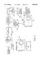
- FIGS. 1A and 1Bshow a flowchart illustrating the method of the present invention used to prepare a reference chart
- FIG. 2is a view of a reference chart produced by the method of FIGS. 1A and 1B;
- FIG. 2Ais an enlarged view of a rendering on the chart of FIG. 2;
- FIG. 3is a flowchart illustrating a kit of the present invention, and a method of the present invention for calibrating a photofinishing system using such a kit.
- a capture film, 102on which the original image, 110, of the scene, 108, is captured, is selected.
- the capture film 102should have wide exposure latitude, high sharpness and good color rendition.
- This filmis used to photograph the reference scene, 108. Additional exposures of the reference scene 108 are also made with the inclusion of various diagnostic charts and devices. Further analytical exposures are additionally produced on the capture film using an exposing device such as a sensitometer, 104, to produce undeveloped sensitometer exposure 106 on the same capture film 102. Since each of the separate photographic and sensitometric exposures on the capture film is used in the determination of the tone and color characteristics of the developed reference scene photograph, they are developed together in a well controlled film processor, 112, in the conventional manner.
- the developed reference scene photograph and diagnostic and sensitometric exposures, 114are scanned using a digital film scanner, 116.
- Optimum qualityrequires the use of a scanner having very high spatial resolution and stable color sensitivities.
- the resulting digital images, 118are in a metric that is scanner dependent and will be called scanner density in this discussion. Scanner density is representative of the opto-electronic response of the scanner system to the optical density modulation in the developed negatives.
- the digital image data (files) resulting from scanning the diagnostic and analytical exposuresare then numerically analyzed.
- the developed negatives of the sensitometric exposuresare also measured using appropriate integral densitometry.
- the data obtainedis then used to determine the capture film and scanner characteristics and thereby construct a digital data transform, 120, that removes the scanner characteristics (such as spectral sensitivity) and the tone and color reproduction characteristics of the capture film from the scanned reference image.
- the components of such a transformmay include, but need not be limited to, particular one-dimensional mapping operations, multi-dimensional lookup tables, matrix operations, interpolation operations, sampling operations, clipping, shifting and scaling operations, the uses of which are familiar to those skilled in the art of digital image processing or other types of data transforming operations.
- the digital image, 122, resulting from application of transform 120is now a representation of the reference scene in terms of exposure density into the three color records of the capture film.
- Exposure densityis a logarithmic quantity representing the imagewise quantity of exposing light reaching each photosensitive record of the capture film.
- the digital image 122 in exposure densityis independent of the color and tone reproduction characteristics of the capture film but is still dependent on the spectral sensitivities of the various photosensitive records of the capture film. That is, digital image 122 carries independent color signals corresponding to the signals sensed in each color channel of the capture film 102 (typically the signals may be in the form of red, green and blue signals, corresponding to the signals sensed by the cyan, magenta and yellow sensitive records of film 102).
- Digital image 122can now be manipulated if desired to change certain image characteristics or to add specific resolution targets or color calibration patches. This is accomplished using digital transform 124, leading to digital image 126, containing the (possibly modified) reference image with added resolution targets or color calibration patches.
- the product film type(the product film type being the type of film for which a calibration kit using the final reference chart, is being designed), has a different spectral sensitivity in its photosensitive record(s) than capture film 102, then it is necessary to develop a second transform, 128 which can transform the exposure densities as sensed by the capture film into exposure densities that would have been sensed by the product film type, producing digital image 130.
- Spectral sensitivity measurements for the photosensitive recording layers of the capture film 102 and the product film typeare required to build this transform. These spectral sensitivities can be obtained in a known manner.
- Digital image 130must now be transformed in a way that digitally models the printing of a negative of the reference image on the product film onto the product photographic paper (a selected type of photographic medium), using a photofinishing system printer, to produce a photographic print of preselected balance. This is accomplished using digital transform 132.
- the resulting digital image, 134represents the exposures that would be recorded in each photosensitive layer of the product photographic paper at the time of printing, if the printer were correctly balanced and calibrated.
- the data required to construct transform 132include spectroscopy and integral densitometry readings of a set of images of color patches on the product film, where the set of color patches represents a reasonably uniform sampling of the color gamut of the film, the power spectrum of the printer lamp and the spectral sensitivities of the various photosensitive layers of the product photographic paper.
- Digital image 134is the basis image from which the reference chart is constructed. Steps 136 through 144 are repetitively applied to build each of the component images for the reference chart.
- Digital transform 136models a photofinishing system printer exposure adjustment (which includes both chromaticity, that is color balance, adjustments, as well as lightness adjustments), so that different exposure levels of the image can be generated which can produce photographic prints on the selected medium (the product type photographic paper) of balances (both color and lightness) offset from the preselected balance. This model can be derived from a study of the printer exposure adjustment mechanisms.
- Digital transform 136also provides for the incorporation of unique reference identifiers (in the form of numbers 1 to 37, and letters A through H and N, as seen on FIG.
- Digital image 138represents represents the exposures that would be recorded in each photosensitive layer of the product photographic paper at the time of printing, for a preselected printer exposure or color balance position.
- the digital image 138can be montaged (that is, integrated) at a preselected location into a larger digital image representing the whole reference chart 154.
- Digital image 142represents the image of the reference chart at various stages of completion, as the component images, 138, are integrated into it.
- Step 144represents the creation of a new digital transform 136 corresponding to a new printer exposure or color balance setting.
- Transform 146converts the reference chart image into a metric suitable for a digital opto-electronic film writer and provides for tone and color calibration of the filmwriter.
- the digital filmwriteroutputs the digital image of the reference chart, 148, producing a film negative 150 of the reference chart, 154. This negative 150 is on a film suitable for use in the digital film writer and may be different from either the capture film or the product film.
- Negative 150prints in a single exposure onto the product paper, exactly (within the limits of modeling error) as would a negative of the reference image, on the product film type, printed at the range of exposure and color balance settings represented on the reference chart.
- the negative of the reference chartis printed photographically, 152, onto the product paper using a photographic printer or enlarger resulting in the reference chart 154.
- Reference chart 154is a chart with 45 different renderings of the same image identified by the hexagons numbered with unique identifier numbers 1 to 37, A to H, and N. Each rendering is different from other renderings by specific amounts of log exposure.
- the renderings of chart 154are preferably printed with the same colorants and on the same substrate 158 as will be used for making photographic prints of a reference film strip 160 carrying unprocessed reference images. More particularly, chart 154 is preferably formed by exposing and processing (that is, developing and fixing the image) the same type of photographic paper as will be used for printing images from the reference film strip 160 and from a customer film strip 170. The exposed and processed paper becomes substrate 158 and the dyes in the paper become the image colorants.
- a photographic mediumsuch as paper or film
- having the same photographic characteristicsand normally references media manufactured in the same way with the same components.
- Reference film strip 160 and customer film strip 170are described below in connection with FIG. 3.
- the color gamut, gloss, contrast, and white point of the printed reference images, reference chart, and printed customer imageswill be identical and an appearance match between the reference image and reference chart can be obtained regardless of viewing conditions.
- the renderingsare in two groups, with all the renderings preferably being on a gray background on substrate 158 to reduce chromatic induction effects.
- a first group of renderingssimulates equally spaced printer exposures resulting in a range of lightness at a constant color balance. This first group is on the left side of chart 154, and vary from Lightest to Darkest, lettered from A to H (A being the lightest of the first group, that is the least exposure, and H being the darkest of the first group, that is the greatest exposure).
- These renderingsare separated by equal changes in log exposure, with D being the rendering recommended by the manufacturer of the kit (hence D has what the manufacturer regards as the recommended density for this scene).
- the second groupchanges in color balance.
- the center patch 1is the recommended color and density (identical to "D" from the left side).
- Adjacent renderings in a given direction on the chartpreferably simulate a constant log exposure difference, such as 0.030 relative log exposure. This difference preferably corresponds to the color correction button increments commonly found on photofinishing optical printers. Thus, all the renderings immediately adjacent to and surrounding a given rendering simulate a constant log exposure offset from that given rendering but in different color directions.
- the different color balance renderingsare achieved by adjusting the relative log exposures in three color dimensions--the red/cyan, green/magenta and yellow/blue axes.
- the yellow/blue exposurewould be increased relative to the red/cyan and magenta/green exposures.
- the changes to these exposuresare made in a way that maintains a constant level of lightness (relative brightness, independent of chromaticity) in the renderings.
- Lightness and chromaticitycan be described, for example, using the CIE L*a*b* color space (see R. W. G. Hunt, The Reproduction of Color Fourth Edition, 1987, Fountain Press, Tolworth, England).
- Chart 154also has a correctly exposed and color balanced rendering N included on the plain gray background of the reference chart to facilitate critical comparison without the distraction of surrounding images.
- Rendering Nis the same as D (which in turn is the same as rendering 1).
- the apparatusis in the form of a kit, and includes reference chart 154, a reference film strip 160, a look up table 162, and an indication that the kit is to be used for establishing a printer calibration for an identified film type or types.
- a kitis meant that all of the elements of the apparatus are provided together (typically in a single package).
- the foregoing indicationmay be in the form of printed instructions associated with the kit (for example, instructions enclosed with the kit or on its packaging) specifying that the kit is for printer calibration for the stated film type or types (preferably for a film type the same as that of the unprocessed reference film strip 160).
- the kitmay additionally comprise an indication that the photographic prints of the reference image are to be made on the same type of photographic medium as the reference chart 154 was made. This indication may be in any of the forms of the previously mentioned indication.
- Look up table 162is shown in the form of the same unique identifiers on reference chart 154, printed in association with corresponding correction factors printed on a paper substrate which are the values for changing the printer output to match a predefined aim rendering (rendering 1 or N, in FIG. 2).
- the kitenables calibration of the printer for customer images made on the same type of film as the reference film strip.
- Reference film strip 160carries latent images (that is, exposed but not processed) of a scene which is suitable for calibrating a printer. This scene would typically contain neutral (that is, one or more gray levels including black and white, which are substantially achromatic) and non-neutral color elements. Preferably the scene would contain multiple objects, and could be a real world scene or computer generated scene.
- the scenewould include human skin colors and other common colors such as sky blue, green foliage, and the like. Most preferably, the scene will be the same as that in the renderings carried by reference chart 154.
- the scenewould be exposed onto the reference filmstrip at a number of different exposure levels, providing at least one normally exposed latent image and one or more latent images that are either under exposed or over exposed.
- a typical reference film stripmay contain images exposed normally, 21/2 stops under exposed, 21/2 stops over exposed and 5 stops over exposed. This facilitates calibration of the photographic printer for negatives of different exposure levels as would typically be encountered in customer orders.
- the reference film strip 160is produced using second generation original methods similar to those described in U.S. Pat. Nos. 5,223,891 and 5,313,251.
- Look up table 162consists of one or more sets of printer adjustment factors corresponding to the differences between the various renderings of the reference image (as identified by the unique identifiers) on the reference chart These adjustment factors correspond to changes in the relative exposure levels in the red/cyan, green/magenta or yellow/blue channels of a photographic printer. By using these adjustment factors the photofinisher is able to change the appearance of prints produced by his photographic printer from matching the density or color balance of a particular rendering on the reference chart to matching the density or color balance of any other rendering on the reference chart.
- the method of using the kit to calibrate a photographic printerbegins with processing of the reference film strip 160 in the film processor 210 of the photofinishing system.
- the photofinishing systemincludes a film processor 210, photographic optical printer 215, and paper processor 230 typically all located at the same single location.
- An advantage of processing the reference film strip at the photofinisher, rather than providing a fully processed film strip in the kit,is that this method accounts for biases that may be present in the film processing operation of the particular photofinishing system.
- the printer calibrationthus obtained will therefore be correct for printing negatives produced using the film processor of the particular photofinishing system rather than simply correct for an ⁇ ideally processed ⁇ film negative. Processing the reference film strip in the film processor produces a strip of reference calibration negatives 212.
- the photofinisherthen makes reference prints of the reference calibration negatives 212 using the printer 215 of the photofinishing system. These prints will most preferably be made on the same type of photographic paper that the reference chart is printed on and that customer prints are made on.
- the reference printsare processed in the paper processor 230 of the photofinishing system.
- the reference prints 220are then compared to the reference image renderings on the reference chart 154. Preferably two comparisons are made--one based on image density using the renderings A to H on the reference chart and the other based on color balance using the renderings 1 to 37 on the reference chart. This comparison is preferably made visually, but reference neutral and/or color patches 156 can be included in the reference image to enable comparison using a densitometer.
- the renderings on the reference chart that match (that is, appear visually to be most similar) the reference prints 220 most closely in density and color balanceare noted.
- the photofinisheralso determines the aim reference rendering on the reference chart. This aim is the rendering having the most desirable color balance and density in the opinion of the photofinisher. Typically the aim rendering recommended by the kit manufacturer, is clearly identified on the reference chart and is generally located in the center of the color balance ring around (that is, rendering number 1 in FIG. 2). If the reference images 220 match the aim rendering then the printer is calibrated. If the reference prints do not match the aim rendering then lookup table 162 is used to determine the printer correction factors needed to obtain output from the printer matching the aim rendering.
- the printer correction factors so obtainedare applied to the printer and a new series of reference prints are made from the reference negatives 212 and processed. These new reference prints are again compared to the reference chart as described above. This cycle may be repeated as necessary until the reference prints match the aim rendering on the reference chart.
- customer films 170 of the same type as the reference film strip 160can be processed in film processor 210 (under the same processing conditions as used for reference film strip 160) and printed using printer 215 onto the same type of photographic paper from which reference chart 154 is made.
- the printed customer imagesare then processed in print processor 230 (under the same processing conditions as used for processing the reference prints). In this way, correctly exposed and color balanced customer prints will be obtained.
- reference film strip 160contains under and over exposed images in addition to the normally exposed image
- printer under and over slope calibrationscan be established to optimally print under and over exposed customer negatives in addition to normally exposed customer negatives.
- look up table 162rather than carrying the correction factors in a human readable form on a substrate, could carry the correction factors in the form of only machine readable data carried by a suitable substrate, such as a machine readable magnetic or optical storage medium (for example, a computer diskette) or solid state memory.
- a suitable substratesuch as a machine readable magnetic or optical storage medium (for example, a computer diskette) or solid state memory.
- the user at a photofinishing labwould need a suitable reader (such as a computer) for this data.
- the correction factors when in the form of machine readable datamay be just carried by the memory of a computer contained as part of a computer controlled printer. This could thereby allow such a computer controlled printer to determine the necessary correction factor to be applied to a printer after the user has made the visual comparison.
- the photographic prints output by printer 215need not be of the reflection kind (that is, they need not be a photographic paper), but could be of the transparent kind for projection or viewing by transmitted (rather than reflected) light.
Landscapes
- Physics & Mathematics (AREA)
- Engineering & Computer Science (AREA)
- Multimedia (AREA)
- Signal Processing (AREA)
- Spectroscopy & Molecular Physics (AREA)
- General Physics & Mathematics (AREA)
- Facsimile Image Signal Circuits (AREA)
- Projection-Type Copiers In General (AREA)
- Control Of Exposure In Printing And Copying (AREA)
- Color Image Communication Systems (AREA)
Abstract
Description
______________________________________ PARTS LIST ______________________________________ 1-37 Unique Idenfifier Numbers 102 Capture Film 104 Sensitometer 106 Sensitometer Exposure 108 Scene 110Original Image 112 Fiim Processor 114 Sensitometric Exposures 116 Digital Film Scanner 118 Digital Image 120 Digital Data Transform 122 Digital Image 124 Digital Transform 126 Ditigal Image 128 Second Transform 130 Digital Image 132 Digital Transform 134 Digital Image 136 Digital Transform 138 Digital Image 140 Steps 142 Digital Image 144 Step 146 Digital Transform 148 Reference Chart 150 Negative 152Step 154 Chart 156 Reference Neutral and/orColor Patches 158Substrate 160Film Strip 162 Look Up Table 170Customer Film Strip 210Film Processor 212Reference Calibration Negatives 215Printer 220Reference Prints 230 Processor ______________________________________
Claims (14)
Priority Applications (5)
| Application Number | Priority Date | Filing Date | Title |
|---|---|---|---|
| US08/794,220US6018381A (en) | 1997-01-30 | 1997-01-30 | Method for calibrating a photofinishing system and components for use in such a method |
| EP98200127AEP0857998B1 (en) | 1997-01-30 | 1998-01-19 | Apparatus and method for calibrating a photofinishing system |
| DE69829326TDE69829326T2 (en) | 1997-01-30 | 1998-01-19 | Apparatus and method for calibrating a photofinishing system |
| JP10011656AJPH10221792A (en) | 1997-01-30 | 1998-01-23 | Method for executing calibration of photograph finishing system and device used for it |
| US09/259,496US6377330B1 (en) | 1997-01-30 | 1999-02-26 | Method for calibrating a photofinishing system and components for use in such a method |
Applications Claiming Priority (1)
| Application Number | Priority Date | Filing Date | Title |
|---|---|---|---|
| US08/794,220US6018381A (en) | 1997-01-30 | 1997-01-30 | Method for calibrating a photofinishing system and components for use in such a method |
Related Child Applications (1)
| Application Number | Title | Priority Date | Filing Date |
|---|---|---|---|
| US09/259,496DivisionUS6377330B1 (en) | 1997-01-30 | 1999-02-26 | Method for calibrating a photofinishing system and components for use in such a method |
Publications (1)
| Publication Number | Publication Date |
|---|---|
| US6018381Atrue US6018381A (en) | 2000-01-25 |
Family
ID=25162055
Family Applications (2)
| Application Number | Title | Priority Date | Filing Date |
|---|---|---|---|
| US08/794,220Expired - LifetimeUS6018381A (en) | 1997-01-30 | 1997-01-30 | Method for calibrating a photofinishing system and components for use in such a method |
| US09/259,496Expired - Fee RelatedUS6377330B1 (en) | 1997-01-30 | 1999-02-26 | Method for calibrating a photofinishing system and components for use in such a method |
Family Applications After (1)
| Application Number | Title | Priority Date | Filing Date |
|---|---|---|---|
| US09/259,496Expired - Fee RelatedUS6377330B1 (en) | 1997-01-30 | 1999-02-26 | Method for calibrating a photofinishing system and components for use in such a method |
Country Status (4)
| Country | Link |
|---|---|
| US (2) | US6018381A (en) |
| EP (1) | EP0857998B1 (en) |
| JP (1) | JPH10221792A (en) |
| DE (1) | DE69829326T2 (en) |
Cited By (10)
| Publication number | Priority date | Publication date | Assignee | Title |
|---|---|---|---|---|
| US6141080A (en)* | 1995-07-12 | 2000-10-31 | Fuji Photo Film Co., Ltd. | Control negative for use in setting up exposure condition of photo-printer |
| US6219446B1 (en)* | 1997-05-21 | 2001-04-17 | Konica Corporation | Image forming apparatus and manufacturing method of lens fitted film unit |
| US6262790B1 (en)* | 1998-03-16 | 2001-07-17 | Fuji Photo Film Co., Ltd. | Printing method, printer and lens-fitted photo film unit |
| US20010010455A1 (en)* | 1998-06-03 | 2001-08-02 | Black & Decker Inc. | Method and apparatus for obtaining product use information |
| US6442497B1 (en)* | 2000-04-14 | 2002-08-27 | Eastman Kodak Company | Calibration method and strip for film scanners in digital photofinishing systems |
| US20030090239A1 (en)* | 2000-04-13 | 2003-05-15 | Kazuyuki Sakakibara | Adapter for battery charger |
| US6628826B1 (en) | 1999-11-29 | 2003-09-30 | Eastman Kodak Company | Color reproduction of images from color films |
| US20070216776A1 (en)* | 2006-03-14 | 2007-09-20 | Xerox Corporation | Color image reproduction |
| US20110149109A1 (en)* | 2009-12-21 | 2011-06-23 | Electronics And Telecommunications Research Institute | Apparatus and method for converting color of taken image |
| US20140368629A1 (en)* | 2011-12-23 | 2014-12-18 | L'oreal | Method for delivering cosmetic advice |
Families Citing this family (14)
| Publication number | Priority date | Publication date | Assignee | Title |
|---|---|---|---|---|
| EP0961482B1 (en)* | 1998-05-28 | 2007-12-12 | Eastman Kodak Company | Digital photofinishing system including digital image processing of alternative capture color photographic media |
| US6154272A (en)* | 1998-10-13 | 2000-11-28 | Eastman Kodak Company | Control tool for and a method of calibrating a photographic processor and photographic printer |
| JP2000255115A (en)* | 1999-03-05 | 2000-09-19 | Sony Corp | Printer apparatus, its photoprinting medium and photoprinting method |
| US6873433B1 (en)* | 2000-03-09 | 2005-03-29 | Eastman Kodak Company | Calibration of color reproduction apparatus |
| US6956966B2 (en) | 2001-04-03 | 2005-10-18 | Electronics For Imaging, Inc. | Method and apparatus for automated image correction for digital image acquisition |
| US7265875B2 (en)* | 2003-07-14 | 2007-09-04 | Kabushiki Kaisha Toshiba | Halftone super-cell optimization for artifact reduction |
| US20050024430A1 (en)* | 2003-07-14 | 2005-02-03 | Kress William C. | Printer profile mapping of input primaries to output primaries |
| US7466445B2 (en)* | 2003-07-14 | 2008-12-16 | Toshiba Corporation | Color and density calibration of color printers |
| EP1626568A1 (en)* | 2004-08-12 | 2006-02-15 | Toshiba Corporation | Color and density calibration of color printers, halftone super-cell optimization for artifact reduction, and printer profile mapping of input primaries to output primaries |
| US8405868B2 (en)* | 2006-09-27 | 2013-03-26 | Andrew Jackson | Method, apparatus and technique for enabling individuals to create and use color |
| USD765699S1 (en)* | 2015-06-06 | 2016-09-06 | Apple Inc. | Display screen or portion thereof with graphical user interface |
| EP3446085A4 (en) | 2016-04-20 | 2020-08-05 | Liefferink, Hauke Maritz | PRESS OPERATOR GOAL, LMD STANDARD AND COLOR CHECK ARRANGEMENT |
| USD861704S1 (en) | 2017-09-11 | 2019-10-01 | Apple Inc. | Electronic device with graphical user interface |
| JP7618994B2 (en)* | 2020-10-06 | 2025-01-22 | 株式会社リコー | Image forming device |
Citations (19)
| Publication number | Priority date | Publication date | Assignee | Title |
|---|---|---|---|---|
| US3292488A (en)* | 1964-05-06 | 1966-12-20 | North American Aviation Inc | Photographic printing means and method |
| US3674364A (en)* | 1970-03-16 | 1972-07-04 | Ventures Res & Dev | Method and apparatus for evaluating color transparencies and the like |
| US3797933A (en)* | 1972-02-03 | 1974-03-19 | Sable Photo Works | Apparatus for making color enlargements |
| CA969400A (en)* | 1971-12-08 | 1975-06-17 | Simon Ratowsky | Printing of colour photographs |
| US4611918A (en)* | 1983-03-24 | 1986-09-16 | Noritsu Kenkya Center Co., Ltd. | Method of determining the optimum exposure conditions for a color printer |
| US4970584A (en)* | 1985-05-15 | 1990-11-13 | Ricoh Company, Ltd. | Method and apparatus for the compensation of color detection |
| US5053808A (en)* | 1988-09-28 | 1991-10-01 | Fuji Photo Film Co., Ltd. | Image forming apparatus |
| US5083154A (en)* | 1990-04-02 | 1992-01-21 | Fuji Photo Film Co., Ltd. | Copying apparatus, print evaluating method for copying apparatus, method for setting printing conditions, and copying apparatus controller |
| US5223891A (en)* | 1991-03-04 | 1993-06-29 | Eastman Kodak Company | Production of second-generation camera-original control tool photographies via photography of digitally-generated transparency of an original scene |
| EP0565283A1 (en)* | 1992-03-29 | 1993-10-13 | Scitex Corporation Ltd. | Apparatus and method for tone and color reproduction control |
| US5262821A (en)* | 1991-06-17 | 1993-11-16 | Fuji Photo Film Co., Ltd. | Condition setup/upkeep print |
| EP0578203A1 (en)* | 1992-07-06 | 1994-01-12 | Eastman Kodak Company | Method and apparatus for forming image data metrics from cascaded photographic imaging systems |
| US5357315A (en)* | 1991-10-30 | 1994-10-18 | Fuji Photo Film Co., Ltd. | Method of determining exposure condition |
| EP0674429A2 (en)* | 1994-03-25 | 1995-09-27 | Eastman Kodak Company | Field calibration method and apparatus for color image reproduction system |
| US5461458A (en)* | 1992-09-15 | 1995-10-24 | Agfa-Gevaert Aktiengesellschaft | Method of automatically controlling exposure when making prints from film from portrait-photography studios |
| EP0751420A1 (en)* | 1995-06-26 | 1997-01-02 | Eastman Kodak Company | Automated photofinishing apparatus |
| DE19625640A1 (en)* | 1995-07-03 | 1997-01-09 | Fuji Photo Film Co Ltd | Control negative for use in adjusting the exposure conditions of photo printers |
| JPH0915760A (en)* | 1995-06-30 | 1997-01-17 | Fuji Color Service Co Ltd | Method for forming photograph processing control tool |
| JPH0915761A (en)* | 1995-06-30 | 1997-01-17 | Fuji Color Service Co Ltd | Method for forming photograph processing control tool |
Family Cites Families (3)
| Publication number | Priority date | Publication date | Assignee | Title |
|---|---|---|---|---|
| US4087180A (en)* | 1977-01-28 | 1978-05-02 | Dinatale Robert F | Photographic printing method |
| JP2914471B2 (en)* | 1993-06-15 | 1999-06-28 | ノーリツ鋼機株式会社 | Monitor image calibration system for image printer |
| US6141080A (en)* | 1995-07-12 | 2000-10-31 | Fuji Photo Film Co., Ltd. | Control negative for use in setting up exposure condition of photo-printer |
- 1997
- 1997-01-30USUS08/794,220patent/US6018381A/ennot_activeExpired - Lifetime
- 1998
- 1998-01-19DEDE69829326Tpatent/DE69829326T2/ennot_activeExpired - Lifetime
- 1998-01-19EPEP98200127Apatent/EP0857998B1/ennot_activeExpired - Lifetime
- 1998-01-23JPJP10011656Apatent/JPH10221792A/enactivePending
- 1999
- 1999-02-26USUS09/259,496patent/US6377330B1/ennot_activeExpired - Fee Related
Patent Citations (20)
| Publication number | Priority date | Publication date | Assignee | Title |
|---|---|---|---|---|
| US3292488A (en)* | 1964-05-06 | 1966-12-20 | North American Aviation Inc | Photographic printing means and method |
| US3674364A (en)* | 1970-03-16 | 1972-07-04 | Ventures Res & Dev | Method and apparatus for evaluating color transparencies and the like |
| CA969400A (en)* | 1971-12-08 | 1975-06-17 | Simon Ratowsky | Printing of colour photographs |
| US3797933A (en)* | 1972-02-03 | 1974-03-19 | Sable Photo Works | Apparatus for making color enlargements |
| US4611918A (en)* | 1983-03-24 | 1986-09-16 | Noritsu Kenkya Center Co., Ltd. | Method of determining the optimum exposure conditions for a color printer |
| US4970584A (en)* | 1985-05-15 | 1990-11-13 | Ricoh Company, Ltd. | Method and apparatus for the compensation of color detection |
| US5053808A (en)* | 1988-09-28 | 1991-10-01 | Fuji Photo Film Co., Ltd. | Image forming apparatus |
| US5083154A (en)* | 1990-04-02 | 1992-01-21 | Fuji Photo Film Co., Ltd. | Copying apparatus, print evaluating method for copying apparatus, method for setting printing conditions, and copying apparatus controller |
| US5223891A (en)* | 1991-03-04 | 1993-06-29 | Eastman Kodak Company | Production of second-generation camera-original control tool photographies via photography of digitally-generated transparency of an original scene |
| US5313251A (en)* | 1991-03-04 | 1994-05-17 | Eastman Kodak Company | Production of second-generation camera-original control tool photographs via photography of digitally generated transparency of a computer-originated image |
| US5262821A (en)* | 1991-06-17 | 1993-11-16 | Fuji Photo Film Co., Ltd. | Condition setup/upkeep print |
| US5357315A (en)* | 1991-10-30 | 1994-10-18 | Fuji Photo Film Co., Ltd. | Method of determining exposure condition |
| EP0565283A1 (en)* | 1992-03-29 | 1993-10-13 | Scitex Corporation Ltd. | Apparatus and method for tone and color reproduction control |
| EP0578203A1 (en)* | 1992-07-06 | 1994-01-12 | Eastman Kodak Company | Method and apparatus for forming image data metrics from cascaded photographic imaging systems |
| US5461458A (en)* | 1992-09-15 | 1995-10-24 | Agfa-Gevaert Aktiengesellschaft | Method of automatically controlling exposure when making prints from film from portrait-photography studios |
| EP0674429A2 (en)* | 1994-03-25 | 1995-09-27 | Eastman Kodak Company | Field calibration method and apparatus for color image reproduction system |
| EP0751420A1 (en)* | 1995-06-26 | 1997-01-02 | Eastman Kodak Company | Automated photofinishing apparatus |
| JPH0915760A (en)* | 1995-06-30 | 1997-01-17 | Fuji Color Service Co Ltd | Method for forming photograph processing control tool |
| JPH0915761A (en)* | 1995-06-30 | 1997-01-17 | Fuji Color Service Co Ltd | Method for forming photograph processing control tool |
| DE19625640A1 (en)* | 1995-07-03 | 1997-01-09 | Fuji Photo Film Co Ltd | Control negative for use in adjusting the exposure conditions of photo printers |
Non-Patent Citations (3)
| Title |
|---|
| Color Printing Techniques, "Analyzing Your Results: Prints from Negatives", The Kodak Workshop Series by Vernon Iuppa and John Smallwood, 1981, pp.26-37. |
| Color Printing Techniques, Analyzing Your Results: Prints from Negatives , The Kodak Workshop Series by Vernon Iuppa and John Smallwood, 1981, pp.26 37.* |
| Film Printing Demonstration Kit Research Disclosure, No. 325, May 1, 1991, p. 366 XP000229721.* |
Cited By (13)
| Publication number | Priority date | Publication date | Assignee | Title |
|---|---|---|---|---|
| US6141080A (en)* | 1995-07-12 | 2000-10-31 | Fuji Photo Film Co., Ltd. | Control negative for use in setting up exposure condition of photo-printer |
| US6219446B1 (en)* | 1997-05-21 | 2001-04-17 | Konica Corporation | Image forming apparatus and manufacturing method of lens fitted film unit |
| US6262790B1 (en)* | 1998-03-16 | 2001-07-17 | Fuji Photo Film Co., Ltd. | Printing method, printer and lens-fitted photo film unit |
| US20010010455A1 (en)* | 1998-06-03 | 2001-08-02 | Black & Decker Inc. | Method and apparatus for obtaining product use information |
| US7138785B2 (en)* | 1998-06-03 | 2006-11-21 | Black & Decker Inc. | Power tool with means for obtaining product use information |
| US6628826B1 (en) | 1999-11-29 | 2003-09-30 | Eastman Kodak Company | Color reproduction of images from color films |
| US20030090239A1 (en)* | 2000-04-13 | 2003-05-15 | Kazuyuki Sakakibara | Adapter for battery charger |
| US6442497B1 (en)* | 2000-04-14 | 2002-08-27 | Eastman Kodak Company | Calibration method and strip for film scanners in digital photofinishing systems |
| US20070216776A1 (en)* | 2006-03-14 | 2007-09-20 | Xerox Corporation | Color image reproduction |
| US20110149109A1 (en)* | 2009-12-21 | 2011-06-23 | Electronics And Telecommunications Research Institute | Apparatus and method for converting color of taken image |
| US20140368629A1 (en)* | 2011-12-23 | 2014-12-18 | L'oreal | Method for delivering cosmetic advice |
| US10213007B2 (en)* | 2011-12-23 | 2019-02-26 | L'oreal | Method for delivering cosmetic advice |
| US10631617B2 (en)* | 2011-12-23 | 2020-04-28 | L'oreal | Method for delivering cosmetic advice |
Also Published As
| Publication number | Publication date |
|---|---|
| DE69829326D1 (en) | 2005-04-21 |
| EP0857998B1 (en) | 2005-03-16 |
| JPH10221792A (en) | 1998-08-21 |
| US6377330B1 (en) | 2002-04-23 |
| DE69829326T2 (en) | 2006-01-26 |
| EP0857998A1 (en) | 1998-08-12 |
Similar Documents
| Publication | Publication Date | Title |
|---|---|---|
| US6018381A (en) | Method for calibrating a photofinishing system and components for use in such a method | |
| US5452111A (en) | Methods and associated apparatus for forming image data metrics which achieve media compatibility for subsequent imaging applications | |
| US5317425A (en) | Technique for use in conjunction with an imaging system for providing an appearance match between two images and for calibrating the system thereto | |
| US5563717A (en) | Method and means for calibration of photographic media using pre-exposed miniature images | |
| EP0587128B1 (en) | Image processing system and method for faithfully reproducing colors of objects from negative film | |
| US6459825B1 (en) | Method and apparatus for a self learning automatic control of photo capture and scanning | |
| US5313251A (en) | Production of second-generation camera-original control tool photographs via photography of digitally generated transparency of a computer-originated image | |
| JPH09197577A (en) | Digital sensitivity correction processing | |
| US7298892B2 (en) | Producing a balanced digital color image having minimal color errors | |
| EP0255127B1 (en) | Simulator for automatic photographic printing apparatus | |
| US5721811A (en) | Pre-press process and system for accurately reproducing color images | |
| US6163389A (en) | Digital photofinishing system including digital image processing of alternative capture color photographic media | |
| US5406325A (en) | Method and apparatus for forming a source-independent image data metric from second generation photographic films | |
| EP0460187B1 (en) | Methods and associated apparatus for forming image data metrics which achieve media compatibility for subsequent imaging applications | |
| JP2955071B2 (en) | Tone conversion method for fading color photographic originals | |
| US5966505A (en) | Image outputting method and converting information producing method | |
| JPH02171736A (en) | Exposure condition setting method for photograph printer | |
| Holm | A strategy for pictorial digital image processing (PDIP) | |
| Tuijn | Input calibration for negative originals | |
| JPH06139323A (en) | Method and system for picture processing capable of faithful reproduction of object color from negative film | |
| US6882451B2 (en) | Method and means for determining estimated relative exposure values from optical density values of photographic media | |
| Kress | Alternatives for the specifications of a color negative film target for input scanner calibration | |
| JP2003066546A (en) | Film chart original plate and film chart | |
| KR950000285B1 (en) | Color fading of faded color photographs | |
| JPH10255037A (en) | Color reproduction correcting method |
Legal Events
| Date | Code | Title | Description |
|---|---|---|---|
| AS | Assignment | Owner name:EASTMAN KODAK COMPANY, NEW YORK Free format text:ASSIGNMENT OF ASSIGNORS INTEREST;ASSIGNORS:VANDERBROOK, PETER;WOOLFE, GEOFFREY J.;REEL/FRAME:008432/0970 Effective date:19970129 Owner name:EASTMAN KODAK COMPANY, NEW YORK Free format text:ASSIGNMENT OF ASSIGNORS INTEREST;ASSIGNORS:VANDERBROOK, PETER;WOOLFE, GEOFFREY J.;REEL/FRAME:008432/0954 Effective date:19970129 | |
| STCF | Information on status: patent grant | Free format text:PATENTED CASE | |
| FEPP | Fee payment procedure | Free format text:PAYOR NUMBER ASSIGNED (ORIGINAL EVENT CODE: ASPN); ENTITY STATUS OF PATENT OWNER: LARGE ENTITY | |
| FPAY | Fee payment | Year of fee payment:4 | |
| FPAY | Fee payment | Year of fee payment:8 | |
| FPAY | Fee payment | Year of fee payment:12 | |
| AS | Assignment | Owner name:CITICORP NORTH AMERICA, INC., AS AGENT, NEW YORK Free format text:SECURITY INTEREST;ASSIGNORS:EASTMAN KODAK COMPANY;PAKON, INC.;REEL/FRAME:028201/0420 Effective date:20120215 | |
| AS | Assignment | Owner name:WILMINGTON TRUST, NATIONAL ASSOCIATION, AS AGENT, Free format text:PATENT SECURITY AGREEMENT;ASSIGNORS:EASTMAN KODAK COMPANY;PAKON, INC.;REEL/FRAME:030122/0235 Effective date:20130322 Owner name:WILMINGTON TRUST, NATIONAL ASSOCIATION, AS AGENT, MINNESOTA Free format text:PATENT SECURITY AGREEMENT;ASSIGNORS:EASTMAN KODAK COMPANY;PAKON, INC.;REEL/FRAME:030122/0235 Effective date:20130322 | |
| AS | Assignment | Owner name:BARCLAYS BANK PLC, AS ADMINISTRATIVE AGENT, NEW YORK Free format text:INTELLECTUAL PROPERTY SECURITY AGREEMENT (SECOND LIEN);ASSIGNORS:EASTMAN KODAK COMPANY;FAR EAST DEVELOPMENT LTD.;FPC INC.;AND OTHERS;REEL/FRAME:031159/0001 Effective date:20130903 Owner name:JPMORGAN CHASE BANK, N.A., AS ADMINISTRATIVE, DELAWARE Free format text:INTELLECTUAL PROPERTY SECURITY AGREEMENT (FIRST LIEN);ASSIGNORS:EASTMAN KODAK COMPANY;FAR EAST DEVELOPMENT LTD.;FPC INC.;AND OTHERS;REEL/FRAME:031158/0001 Effective date:20130903 Owner name:BARCLAYS BANK PLC, AS ADMINISTRATIVE AGENT, NEW YO Free format text:INTELLECTUAL PROPERTY SECURITY AGREEMENT (SECOND LIEN);ASSIGNORS:EASTMAN KODAK COMPANY;FAR EAST DEVELOPMENT LTD.;FPC INC.;AND OTHERS;REEL/FRAME:031159/0001 Effective date:20130903 Owner name:JPMORGAN CHASE BANK, N.A., AS ADMINISTRATIVE, DELA Free format text:INTELLECTUAL PROPERTY SECURITY AGREEMENT (FIRST LIEN);ASSIGNORS:EASTMAN KODAK COMPANY;FAR EAST DEVELOPMENT LTD.;FPC INC.;AND OTHERS;REEL/FRAME:031158/0001 Effective date:20130903 Owner name:PAKON, INC., NEW YORK Free format text:RELEASE OF SECURITY INTEREST IN PATENTS;ASSIGNORS:CITICORP NORTH AMERICA, INC., AS SENIOR DIP AGENT;WILMINGTON TRUST, NATIONAL ASSOCIATION, AS JUNIOR DIP AGENT;REEL/FRAME:031157/0451 Effective date:20130903 Owner name:EASTMAN KODAK COMPANY, NEW YORK Free format text:RELEASE OF SECURITY INTEREST IN PATENTS;ASSIGNORS:CITICORP NORTH AMERICA, INC., AS SENIOR DIP AGENT;WILMINGTON TRUST, NATIONAL ASSOCIATION, AS JUNIOR DIP AGENT;REEL/FRAME:031157/0451 Effective date:20130903 Owner name:BANK OF AMERICA N.A., AS AGENT, MASSACHUSETTS Free format text:INTELLECTUAL PROPERTY SECURITY AGREEMENT (ABL);ASSIGNORS:EASTMAN KODAK COMPANY;FAR EAST DEVELOPMENT LTD.;FPC INC.;AND OTHERS;REEL/FRAME:031162/0117 Effective date:20130903 | |
| AS | Assignment | Owner name:EASTMAN KODAK COMPANY, NEW YORK Free format text:RELEASE BY SECURED PARTY;ASSIGNOR:BARCLAYS BANK PLC;REEL/FRAME:041656/0531 Effective date:20170202 | |
| AS | Assignment | Owner name:KODAK AMERICAS, LTD., NEW YORK Free format text:RELEASE BY SECURED PARTY;ASSIGNOR:JP MORGAN CHASE BANK, N.A., AS ADMINISTRATIVE AGENT;REEL/FRAME:049814/0001 Effective date:20190617 Owner name:FAR EAST DEVELOPMENT LTD., NEW YORK Free format text:RELEASE BY SECURED PARTY;ASSIGNOR:JP MORGAN CHASE BANK, N.A., AS ADMINISTRATIVE AGENT;REEL/FRAME:049814/0001 Effective date:20190617 Owner name:KODAK (NEAR EAST), INC., NEW YORK Free format text:RELEASE BY SECURED PARTY;ASSIGNOR:JP MORGAN CHASE BANK, N.A., AS ADMINISTRATIVE AGENT;REEL/FRAME:049814/0001 Effective date:20190617 Owner name:EASTMAN KODAK COMPANY, NEW YORK Free format text:RELEASE BY SECURED PARTY;ASSIGNOR:JP MORGAN CHASE BANK, N.A., AS ADMINISTRATIVE AGENT;REEL/FRAME:049814/0001 Effective date:20190617 Owner name:PAKON, INC., NEW YORK Free format text:RELEASE BY SECURED PARTY;ASSIGNOR:JP MORGAN CHASE BANK, N.A., AS ADMINISTRATIVE AGENT;REEL/FRAME:049814/0001 Effective date:20190617 Owner name:KODAK AVIATION LEASING LLC, NEW YORK Free format text:RELEASE BY SECURED PARTY;ASSIGNOR:JP MORGAN CHASE BANK, N.A., AS ADMINISTRATIVE AGENT;REEL/FRAME:049814/0001 Effective date:20190617 Owner name:KODAK PORTUGUESA LIMITED, NEW YORK Free format text:RELEASE BY SECURED PARTY;ASSIGNOR:JP MORGAN CHASE BANK, N.A., AS ADMINISTRATIVE AGENT;REEL/FRAME:049814/0001 Effective date:20190617 Owner name:LASER PACIFIC MEDIA CORPORATION, NEW YORK Free format text:RELEASE BY SECURED PARTY;ASSIGNOR:JP MORGAN CHASE BANK, N.A., AS ADMINISTRATIVE AGENT;REEL/FRAME:049814/0001 Effective date:20190617 Owner name:KODAK IMAGING NETWORK, INC., NEW YORK Free format text:RELEASE BY SECURED PARTY;ASSIGNOR:JP MORGAN CHASE BANK, N.A., AS ADMINISTRATIVE AGENT;REEL/FRAME:049814/0001 Effective date:20190617 Owner name:CREO MANUFACTURING AMERICA LLC, NEW YORK Free format text:RELEASE BY SECURED PARTY;ASSIGNOR:JP MORGAN CHASE BANK, N.A., AS ADMINISTRATIVE AGENT;REEL/FRAME:049814/0001 Effective date:20190617 Owner name:KODAK REALTY, INC., NEW YORK Free format text:RELEASE BY SECURED PARTY;ASSIGNOR:JP MORGAN CHASE BANK, N.A., AS ADMINISTRATIVE AGENT;REEL/FRAME:049814/0001 Effective date:20190617 Owner name:QUALEX, INC., NEW YORK Free format text:RELEASE BY SECURED PARTY;ASSIGNOR:JP MORGAN CHASE BANK, N.A., AS ADMINISTRATIVE AGENT;REEL/FRAME:049814/0001 Effective date:20190617 Owner name:NPEC, INC., NEW YORK Free format text:RELEASE BY SECURED PARTY;ASSIGNOR:JP MORGAN CHASE BANK, N.A., AS ADMINISTRATIVE AGENT;REEL/FRAME:049814/0001 Effective date:20190617 Owner name:KODAK PHILIPPINES, LTD., NEW YORK Free format text:RELEASE BY SECURED PARTY;ASSIGNOR:JP MORGAN CHASE BANK, N.A., AS ADMINISTRATIVE AGENT;REEL/FRAME:049814/0001 Effective date:20190617 Owner name:FPC, INC., NEW YORK Free format text:RELEASE BY SECURED PARTY;ASSIGNOR:JP MORGAN CHASE BANK, N.A., AS ADMINISTRATIVE AGENT;REEL/FRAME:049814/0001 Effective date:20190617 | |
| AS | Assignment | Owner name:KODAK REALTY INC., NEW YORK Free format text:RELEASE BY SECURED PARTY;ASSIGNOR:BARCLAYS BANK PLC;REEL/FRAME:052773/0001 Effective date:20170202 Owner name:FPC INC., NEW YORK Free format text:RELEASE BY SECURED PARTY;ASSIGNOR:BARCLAYS BANK PLC;REEL/FRAME:052773/0001 Effective date:20170202 Owner name:LASER PACIFIC MEDIA CORPORATION, NEW YORK Free format text:RELEASE BY SECURED PARTY;ASSIGNOR:BARCLAYS BANK PLC;REEL/FRAME:052773/0001 Effective date:20170202 Owner name:KODAK (NEAR EAST) INC., NEW YORK Free format text:RELEASE BY SECURED PARTY;ASSIGNOR:BARCLAYS BANK PLC;REEL/FRAME:052773/0001 Effective date:20170202 Owner name:NPEC INC., NEW YORK Free format text:RELEASE BY SECURED PARTY;ASSIGNOR:BARCLAYS BANK PLC;REEL/FRAME:052773/0001 Effective date:20170202 Owner name:FAR EAST DEVELOPMENT LTD., NEW YORK Free format text:RELEASE BY SECURED PARTY;ASSIGNOR:BARCLAYS BANK PLC;REEL/FRAME:052773/0001 Effective date:20170202 Owner name:KODAK AMERICAS LTD., NEW YORK Free format text:RELEASE BY SECURED PARTY;ASSIGNOR:BARCLAYS BANK PLC;REEL/FRAME:052773/0001 Effective date:20170202 Owner name:QUALEX INC., NEW YORK Free format text:RELEASE BY SECURED PARTY;ASSIGNOR:BARCLAYS BANK PLC;REEL/FRAME:052773/0001 Effective date:20170202 Owner name:EASTMAN KODAK COMPANY, NEW YORK Free format text:RELEASE BY SECURED PARTY;ASSIGNOR:BARCLAYS BANK PLC;REEL/FRAME:052773/0001 Effective date:20170202 Owner name:KODAK PHILIPPINES LTD., NEW YORK Free format text:RELEASE BY SECURED PARTY;ASSIGNOR:BARCLAYS BANK PLC;REEL/FRAME:052773/0001 Effective date:20170202 |