US6018208A - Articulated motor stator assembly for a pump - Google Patents
Articulated motor stator assembly for a pumpDownload PDFInfo
- Publication number
- US6018208A US6018208AUS09/237,731US23773199AUS6018208AUS 6018208 AUS6018208 AUS 6018208AUS 23773199 AUS23773199 AUS 23773199AUS 6018208 AUS6018208 AUS 6018208A
- Authority
- US
- United States
- Prior art keywords
- assembly
- motor stator
- motor
- sub
- stator assembly
- Prior art date
- Legal status (The legal status is an assumption and is not a legal conclusion. Google has not performed a legal analysis and makes no representation as to the accuracy of the status listed.)
- Expired - Fee Related
Links
Images


Classifications
- H—ELECTRICITY
- H02—GENERATION; CONVERSION OR DISTRIBUTION OF ELECTRIC POWER
- H02K—DYNAMO-ELECTRIC MACHINES
- H02K15/00—Processes or apparatus specially adapted for manufacturing, assembling, maintaining or repairing of dynamo-electric machines
- H02K15/50—Disassembling, repairing or modifying dynamo-electric machines
- A—HUMAN NECESSITIES
- A61—MEDICAL OR VETERINARY SCIENCE; HYGIENE
- A61M—DEVICES FOR INTRODUCING MEDIA INTO, OR ONTO, THE BODY; DEVICES FOR TRANSDUCING BODY MEDIA OR FOR TAKING MEDIA FROM THE BODY; DEVICES FOR PRODUCING OR ENDING SLEEP OR STUPOR
- A61M60/00—Blood pumps; Devices for mechanical circulatory actuation; Balloon pumps for circulatory assistance
- A61M60/10—Location thereof with respect to the patient's body
- A61M60/104—Extracorporeal pumps, i.e. the blood being pumped outside the patient's body
- A61M60/117—Extracorporeal pumps, i.e. the blood being pumped outside the patient's body for assisting the heart, e.g. transcutaneous or external ventricular assist devices
- A—HUMAN NECESSITIES
- A61—MEDICAL OR VETERINARY SCIENCE; HYGIENE
- A61M—DEVICES FOR INTRODUCING MEDIA INTO, OR ONTO, THE BODY; DEVICES FOR TRANSDUCING BODY MEDIA OR FOR TAKING MEDIA FROM THE BODY; DEVICES FOR PRODUCING OR ENDING SLEEP OR STUPOR
- A61M60/00—Blood pumps; Devices for mechanical circulatory actuation; Balloon pumps for circulatory assistance
- A61M60/20—Type thereof
- A61M60/205—Non-positive displacement blood pumps
- A61M60/216—Non-positive displacement blood pumps including a rotating member acting on the blood, e.g. impeller
- A61M60/226—Non-positive displacement blood pumps including a rotating member acting on the blood, e.g. impeller the blood flow through the rotating member having mainly radial components
- A61M60/232—Centrifugal pumps
- A—HUMAN NECESSITIES
- A61—MEDICAL OR VETERINARY SCIENCE; HYGIENE
- A61M—DEVICES FOR INTRODUCING MEDIA INTO, OR ONTO, THE BODY; DEVICES FOR TRANSDUCING BODY MEDIA OR FOR TAKING MEDIA FROM THE BODY; DEVICES FOR PRODUCING OR ENDING SLEEP OR STUPOR
- A61M60/00—Blood pumps; Devices for mechanical circulatory actuation; Balloon pumps for circulatory assistance
- A61M60/20—Type thereof
- A61M60/205—Non-positive displacement blood pumps
- A61M60/216—Non-positive displacement blood pumps including a rotating member acting on the blood, e.g. impeller
- A61M60/237—Non-positive displacement blood pumps including a rotating member acting on the blood, e.g. impeller the blood flow through the rotating member having mainly axial components, e.g. axial flow pumps
- A—HUMAN NECESSITIES
- A61—MEDICAL OR VETERINARY SCIENCE; HYGIENE
- A61M—DEVICES FOR INTRODUCING MEDIA INTO, OR ONTO, THE BODY; DEVICES FOR TRANSDUCING BODY MEDIA OR FOR TAKING MEDIA FROM THE BODY; DEVICES FOR PRODUCING OR ENDING SLEEP OR STUPOR
- A61M60/00—Blood pumps; Devices for mechanical circulatory actuation; Balloon pumps for circulatory assistance
- A61M60/40—Details relating to driving
- A61M60/403—Details relating to driving for non-positive displacement blood pumps
- A61M60/422—Details relating to driving for non-positive displacement blood pumps the force acting on the blood contacting member being electromagnetic, e.g. using canned motor pumps
- A—HUMAN NECESSITIES
- A61—MEDICAL OR VETERINARY SCIENCE; HYGIENE
- A61M—DEVICES FOR INTRODUCING MEDIA INTO, OR ONTO, THE BODY; DEVICES FOR TRANSDUCING BODY MEDIA OR FOR TAKING MEDIA FROM THE BODY; DEVICES FOR PRODUCING OR ENDING SLEEP OR STUPOR
- A61M60/00—Blood pumps; Devices for mechanical circulatory actuation; Balloon pumps for circulatory assistance
- A61M60/80—Constructional details other than related to driving
- A61M60/802—Constructional details other than related to driving of non-positive displacement blood pumps
- A61M60/818—Bearings
- A61M60/825—Contact bearings, e.g. ball-and-cup or pivot bearings
- A—HUMAN NECESSITIES
- A61—MEDICAL OR VETERINARY SCIENCE; HYGIENE
- A61M—DEVICES FOR INTRODUCING MEDIA INTO, OR ONTO, THE BODY; DEVICES FOR TRANSDUCING BODY MEDIA OR FOR TAKING MEDIA FROM THE BODY; DEVICES FOR PRODUCING OR ENDING SLEEP OR STUPOR
- A61M60/00—Blood pumps; Devices for mechanical circulatory actuation; Balloon pumps for circulatory assistance
- A61M60/80—Constructional details other than related to driving
- A61M60/802—Constructional details other than related to driving of non-positive displacement blood pumps
- A61M60/827—Sealings between moving parts
- H—ELECTRICITY
- H02—GENERATION; CONVERSION OR DISTRIBUTION OF ELECTRIC POWER
- H02K—DYNAMO-ELECTRIC MACHINES
- H02K1/00—Details of the magnetic circuit
- H02K1/06—Details of the magnetic circuit characterised by the shape, form or construction
- H02K1/12—Stationary parts of the magnetic circuit
- H02K1/14—Stator cores with salient poles
- H02K1/146—Stator cores with salient poles consisting of a generally annular yoke with salient poles
- H02K1/148—Sectional cores
- H—ELECTRICITY
- H02—GENERATION; CONVERSION OR DISTRIBUTION OF ELECTRIC POWER
- H02K—DYNAMO-ELECTRIC MACHINES
- H02K5/00—Casings; Enclosures; Supports
- H02K5/04—Casings or enclosures characterised by the shape, form or construction thereof
- H02K5/12—Casings or enclosures characterised by the shape, form or construction thereof specially adapted for operating in liquid or gas
- H02K5/128—Casings or enclosures characterised by the shape, form or construction thereof specially adapted for operating in liquid or gas using air-gap sleeves or air-gap discs
- A—HUMAN NECESSITIES
- A61—MEDICAL OR VETERINARY SCIENCE; HYGIENE
- A61M—DEVICES FOR INTRODUCING MEDIA INTO, OR ONTO, THE BODY; DEVICES FOR TRANSDUCING BODY MEDIA OR FOR TAKING MEDIA FROM THE BODY; DEVICES FOR PRODUCING OR ENDING SLEEP OR STUPOR
- A61M60/00—Blood pumps; Devices for mechanical circulatory actuation; Balloon pumps for circulatory assistance
- A61M60/10—Location thereof with respect to the patient's body
- A61M60/122—Implantable pumps or pumping devices, i.e. the blood being pumped inside the patient's body
- A61M60/126—Implantable pumps or pumping devices, i.e. the blood being pumped inside the patient's body implantable via, into, inside, in line, branching on, or around a blood vessel
- A61M60/148—Implantable pumps or pumping devices, i.e. the blood being pumped inside the patient's body implantable via, into, inside, in line, branching on, or around a blood vessel in line with a blood vessel using resection or like techniques, e.g. permanent endovascular heart assist devices
- Y—GENERAL TAGGING OF NEW TECHNOLOGICAL DEVELOPMENTS; GENERAL TAGGING OF CROSS-SECTIONAL TECHNOLOGIES SPANNING OVER SEVERAL SECTIONS OF THE IPC; TECHNICAL SUBJECTS COVERED BY FORMER USPC CROSS-REFERENCE ART COLLECTIONS [XRACs] AND DIGESTS
- Y10—TECHNICAL SUBJECTS COVERED BY FORMER USPC
- Y10S—TECHNICAL SUBJECTS COVERED BY FORMER USPC CROSS-REFERENCE ART COLLECTIONS [XRACs] AND DIGESTS
- Y10S415/00—Rotary kinetic fluid motors or pumps
- Y10S415/90—Rotary blood pump
Definitions
- the present inventionrelates to electric motor assemblies and, more particularly, to pump motor stator assemblies that may be useful, e.g., in blood pump applications.
- a number of implantable blood pumpspresently are under development for application as either artificial hearts or cardiac assist devices. Both centrifugal and axial-flow pumps can be utilized in blood pumps.
- a typical blood pumpincludes a pump housing that defines an inflow port, an outflow port, a pumping chamber, an impeller mechanism mounted within the pumping chamber, an electric motor rotor coupled to the impeller mechanism for blood pumping action, and an electric motor stator that actuates the rotor by an electromagnetic force.
- the impeller mechanismcan be mechanically coupled to the rotor via a transmission shaft as in, for example, a centrifugal-flow type pump.
- the impeller mechanism or bladescan be attached directly to the rotor as in, for example, an axial-flow pump.
- the motor statortypically includes three or more groups of windings. Each winding group is formed from a conductive wire wound around a stack of metallic stampings.
- the motor rotorcontains a permanent magnet. In effect, the stator and rotor together form a brushless dc motor.
- the windingsare disposed around the rotor.
- the statoris annular in shape, forming a ring-like structure that extends around the rotor.
- the stator windingsare sequentially energized, which creates a rotating magnetic field that drives the rotor about its longitudinal axis.
- the annular statoris positioned in the wall of the pump housing, around the rotor.
- the statorIn axial-flow pump designs, the stator is mounted about the blood flow conduit. In centrifugal-flow pumps, the stator is mounted about a rotor neck that is connected to an impeller mechanism located within the blood flow.
- blood pumpsIn view of an application of a blood pump in artificial hearts and/or cardiac assist devices, reliability is a critical performance factor. Moreover, blood pumps must ensure that a patient's blood does not become contaminated during use of the pump by blood contacting pump parts that are outside of the blood conduit. As such, pump components are machined to exacting specifications to minimize pump failure and ensure the integrity of the blood pathway. Consequently, pump components are often very expensive. Accordingly, design improvements that can decrease overall consumer cost remain a constant focus of blood pump development.
- the present inventionis directed to an articulating motor stator and a pump incorporating such a stator.
- the articulating motor statoris particularly useful for blood pumps, but may find ready application in other rotary pump applications, including both centrifugal and axial flow arrangements.
- Blood pumpsare often used on human patients for short time periods, during surgery or other medical procedures, or while the patient is in, or recovering from, a critical condition. Even though after use a pump may remain in perfect working condition, the entire pump is often discarded rather than being reused. Such pump disposal protects against exposing a subsequent patient to infection or other bio-incompatibilities contained within a usual pump. Nevertheless, it is desirable to recycle and re-sterilize the expensive components of a blood pump, e.g. the stator, between patients or when other parts of the pump require replacement.
- An articulated or hinged motor statorallows convenient installation and removal of the stator relative to a blood flow conduit containing a rotor element and an associated impeller mechanism. In this manner, the stator can be readily removed from a pump for repair, maintenance, replacement, or reuse. In particular, the articulating motor stator can be reused in multiple pumps.
- An articulated motor stator in accordance with an embodiment of the present inventionis useful for blood pumping applications and, more particularly, can be used in an extracorporeal blood pump.
- An articulated motor stator in accordance with the present inventionprovides a cost effective alternative to replacing an entire pump when only a portion of the pump has failed. This advantage is significant because the motor stator cost is a significant portion of the total cost of a blood pump. Additionally, a removable articulating stator placed outside a patient's sterile field can be immediately re-used or replaced without requiring a cleaning or sterilization step.
- a motor stator assembly constructed according to the present inventionallows the stator assembly to be opened, the motor rotor removed and replaced, and the original stator assembly to be quickly re-assembled and reused.
- Such a motor stator assemblyis substantially annular in shape and is constructed of two or more sub-assemblies, defining distinct azimuthal parts of the motor stator assembly.
- the sub-assembliescan be mechanically connected via hinges, allowing opening and closing of the motor stator assembly in a clamshell-like manner.
- the stator windingsare electrically connected to electrically conductive terminals mounted within the housing via flexible interconnections, so that electrical continuity between the windings and terminals is unaffected by opening and closing the stator.
- a motor stator assembly constructed according to the present inventionalso enables convenient manufacture, testing, and installation without significant risk of stator damage.
- the motor stator assemblymay form a discrete component that may be added to, or removed from, the blood pump with ease, enabling separate manufacture and shipment from a remote location.
- several motor rotor assembliesmay be easily tested with one motor stator assembly of the present invention in order to optimize the match between the two components of the motor.
- the motor rotor assembly and blood conduitmay be connected to blood vessels in a sterile environment, followed by installation of the motor stator assembly about the blood conduit.
- the present inventionprovides a motor stator assembly for use in a blood pump, the motor stator assembly defining a central aperture configured to receive a motor rotor assembly wherein the motor stator includes stator windings and a housing enclosing the motor stator wherein the housing contains two or more sub-assemblies that are selectively repositionable to allow installation and removal of the motor stator relative to the rotor assembly.
- the present inventionprovides a motor stator assembly for use in a blood pump, the motor stator assembly defining a central aperture configured to receive a motor rotor assembly, a motor stator that includes stator windings, and a housing enclosing the motor stator, wherein the housing contains two or more sub-assemblies that are selectively repositionable to allow installation and removal of the motor stator relative to the motor rotor assembly, and wherein the sub-assemblies are mechanically joined by, and pivotable about, hinge members to define an open configuration in which the sub-assemblies extend away from each other, and a closed configuration in which the sub-assemblies extend towards each other to define a substantially annular aperture for receipt of the motor rotor assembly.
- the present inventionprovides a motor stator assembly for use in a blood pump, the motor stator assembly containing a central aperture configured to receive a motor rotor assembly, a motor stator that includes stator windings and that is substantially annular in shape, thereby defining a ring-like portion and a conduit, and wherein the assembly includes a plurality of sub-assemblies, each subassembly forming an azimuthal portion of the assembly and containing an azimuthal portion of the motor stator.
- the present inventionprovides a motor stator assembly for use in a blood pump containing a central aperture configured to receive a motor rotor assembly, a motor stator, being substantially annular in shape and thereby defining a ring-like portion and a conduit, wherein the motor stator includes stator windings, and wherein the assembly contains a plurality of sub-assemblies, wherein each sub-assembly forms an azimuthal portion of the assembly and contains an azimuthal portion of the motor stator, and wherein one or more sub-assemblies are mechanically joined by, and pivotable about, hinge members, to define an open configuration in which the sub-assemblies extend away from each other, and a closed configuration in which the sub-assemblies extend towards each other to define a substantially annular aperture for receipt of the motor rotor assembly.
- the present inventionprovides a blood pump containing a central aperture configured to receive a motor rotor assembly, a motor stator, wherein the motor stator is substantially annular in shape and thereby defines a ring-like portion and a conduit, and wherein the motor stator includes stator windings, a motor stator assembly containing a plurality of sub-assemblies, wherein each distinct assembly forms an azimuthal portion of the motor stator assembly and contains an azimuthal portion of the motor stator, and wherein one or more sub-assemblies are mechanically joined by, and pivotable about, hinge members, to define an open configuration in which the sub-assemblies extend away from each other, and a closed configuration in which the subassemblies extend towards each other to define a substantially annular aperture for receipt of a motor rotor assembly, and a motor rotor that fits within the motor stator assembly, the motor rotor assembly being so positioned within the motor stator assembly as to cooperate with the motor stator
- the present inventionprovides a method of assembling a blood pump, the blood pump containing a motor stator assembly, including a central aperture configured to receive a motor rotor assembly, wherein the motor stator assembly is substantially annular in shape and thereby defines a ring-like portion and a conduit, and wherein the motor stator assembly includes stator windings, and wherein the motor stator assembly contains a plurality of sub-assemblies, each sub-assembly including a portion of the motor stator, by selectively positioning the sub-assemblies in an open configuration to install the motor rotor assembly within the motor stator assembly and selectively repositioning the sub-assemblies in a closed configuration so that the motor stator assembly fits snugly around the motor rotor assembly.
- the present inventionprovides a method of connecting a blood pump to a living being, the blood pump containing a motor rotor assembly including a blood flow conduit, a motor stator assembly including a central aperture configured to receive the motor rotor assembly, wherein the motor stator assembly is substantially annular in shape and thereby defines a ring-like portion and a conduit, and wherein the motor stator assembly includes stator windings, and wherein the motor stator assembly contains a plurality of sub-assemblies, each sub-assembly including a portion of the motor stator, and wherein the blood flow conduit of the motor rotor assembly is attached to the blood vessels of the living being, and wherein the sub-assemblies are selectively positioned in an open configuration to install the motor stator assembly about the motor rotor assembly connected to the living being, and wherein the motor stator's sub-assemblies are selectively repositioned in a closed configuration so that the motor stator assembly fits snugly around the motor rotor
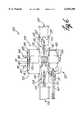
- FIG. 1is a longitudinal cross-sectional diagram depicting a centrifugal-flow blood pump incorporating an articulating motor stator incorporating aspects of the invention
- FIG. 2is an end view, depicting the motor stator assembly of FIG. 1;
- FIG. 3is another end view, depicting the motor stator assembly of FIG. 1;
- FIG. 4is a conceptual cross-sectional end view of the motor stator assembly of FIG. 1 in a closed position
- FIG. 5is a conceptual cross-sectional end view of the motor stator assembly of FIG. 1 in an open position
- FIG. 6is a longitudinal cross-sectional side view diagram depicting an axial-flow blood pump incorporating an articulating motor stator
- FIG. 7is an end view of the motor stator assembly of FIG. 6.
- FIG. 8is another end view of the motor stator assembly of FIG. 6.
- FIG. 1is a longitudinal cross-sectional diagram of a centrifugal-flow blood pump 10 incorporating an articulating stator motor assembly 12 in accordance with an embodiment of the present invention.
- Pump 10can be connected to an animal, e.g. a human, to function as an artificial heart or a cardiac assist device.
- pump 10includes a housing 14 having an inflow portion 16 and an outflow portion 18.
- Inflow portion 16has an inflow opening 22 through which blood enters blood pumping chamber 20.
- Outflow portion 18has an outflow opening 24 through which blood exits pumping chamber 20.
- Inflow and outflow portions, 16, 18can be fitted with additional hardware (not shown) designed to be joined with the cardiovascular system for operation.
- Rotor 26is mounted within bearing blocks 30 and coupled to transmission shaft 28.
- Impeller blades 32, 34are mounted on transmission shaft 28 and oriented to impart centrifugal pumping energy to the blood flow upon actuation of the rotor.
- a seal 27can be provided about transmission shaft 28 between rotor 26 and impeller blades 32, 34. In FIG. 1, only two impeller blades 32, 34 are visible. However, transmission shaft 28 may carry three or more impeller blades, each arranged, for example, in a fan-like pattern.
- Housing 14 and the other components of pump 10can be fabricated from bio-compatible materials.
- Motor stator assembly 12is generally annular in shape, defining a central conduit 29 for receiving the motor rotor assembly 31. Motor rotor assembly 31 is held in place by locating piece 35, which is seated on flanges 19. With further reference to FIG. 1, motor stator assembly 12 includes a stator housing 40 that encloses a motor stator 42. Motor stator 42 has three or more separate groups of electrical windings 43 that surround metal stampings 52, 54. An electrical conduit 60 is coupled to the motor stator assembly 12. Electrical conduit 60 carries electrical cables to motor stator assembly 12 for connection to the electrical windings 43 of metal stampings 54. Electric current is supplied to additional winding groups 43 via flexible cable connections 62, 63 (63 not shown in FIG. 1).
- FIG. 2is an end view of the motor stator assembly 12 illustrating the electrical connections of subassemblies 72, 74, 76 that when together define a substantially annular central conduit 29.
- Currentis supplied to the motor stator assembly 12 via electrical conduit 60.
- Subassemblies 72, 74, 76are supplied electrical current via flexible interconnectors 62, 63.
- Three phase currentcan be applied to motor stator assembly 12.
- each subassembly 72, 74, 76would receive one phase.
- each subassembly 72, 74, 76would have one hot and one return wire coupled to its windings.
- all of the leadsenter motor stator assembly 12 via electrical conduit 60 in subassembly 76.
- Individual leads and returnsare routed from subassembly 76 to subassemblies 72, 74 via flexible interconnectors 62, 63.
- stator housings 40that cover each of subassemblies 72, 74, 76.
- Each stator housing 40can be attached to stator 42 (not pictured) by any conventional manner.
- housing 40is attached to a stator by screws 81.
- Each of subassemblies 72, 74, 76can be filled with an insulating or damping material, if desired, to electrically and mechanically isolate the stator windings from housing 40.
- Subassemblies 72, 74, 76are connected via hinges 78, 80 and a detent locking mechanism 82, which incorporates tab 47 (explained in detail below).
- Stator housing 40can be of alternative designs.
- stator housing 40can be designed to extend across the entire, part, or none of the motor stator. As depicted in FIG. 1, stator housing 40 extends the entire length of the motor stator 42. Furthermore, although the motor stator assembly 20 of FIGS. 1-5 contains three subassemblies, it is to be understood that the motor stator assembly 20 can be constructed from two or more subassemblies.
- FIG. 3is conceptual end view of motor stator assembly 12 viewed from the pump 10 side. Pump 10 and motor stator housings 40 are shown as being removed in FIG. 3 to facilitate the view of motor stator assembly 12.
- subassemblies 72, 74, 76 of motor stator 42surround the central conduit 29 wherein the motor rotor assembly 31 (not shown) is placed during operation.
- Motor stator 42has three or more stacks of metal stampings 50, 52, 54 surrounded by a ring-like portion 65. Metal stampings 50, 52, 54 are wrapped by wire windings 43 (not pictured) that occupy the winding space 56. Attached to the ringlike portion 65 are multiple cooling fins 70 designed to dissipate heat generated by the motor stator 42.
- motor stator sub-assemblies 72, 74, 76can be mechanically connected to each other via hinges 78, 80 and detent locking mechanism 82.
- Hinges 78 and 80comprise hollow cylinders 88, 90, and cylindrical pivot pins 84, 86 whose outer diameter is nearly equal to the inner diameter of hollow cylinders 88, 90.
- Hinges 78, 80provide pivot points about which the subassemblies 72, 74, 76 rotate when the detent locking mechanism 82 is opened.
- stator subassemblies 72, 74, 76 in accordance with the present inventionmay be coupled via an acceptable manner that enables the subassemblies to articulate about a pivot point. Together, the stator subassemblies 72, 74, 76 articulate to a point such that a motor rotor can be radially extracted from or inserted in central conduit 29 when the stator subassemblies are in an opened configuration.
- FIGS. 4 and 5conceptually depict the closed and open configuration of the motor assembly 12, respectively.
- the motor rotor assembly 31(not pictured) occupies the central conduit 29 and fits somewhat snugly within metal stampings 50, 52, 54.
- Motor rotor assembly 31can be separated from the inner walls of conduit 29 and motor stator assembly 12 by a tube, if desired.
- a tubeFor a centrifugal application in which the rotor assembly 31 is not in contact with the pumping fluid, separation may not be necessary.
- an additional tubeordinarily will be used.
- the distance between the subassemblies 72, 74, 76will change when the motor stator 12 is opened.
- the flexible cable interconnections 62, 63should be sufficiently long and flexible to allow the opening of the motor stator 12 without damaging the electrical connections. This can be achieved by manufacturing methods known to those of skill in the art.
- motor stator sub-assemblies 72, 74, 76are in their open position, as in FIG. 5, an azimuthal gap 17 exists between two of the sub-assemblies. Azimuthal gap 17 should be large enough to allow motor rotor assembly 31 to be radially extracted from motor stator assembly 12.
- motor stator 12is opened and closed using a detent locking mechanism 82.
- the detent locking mechanism 82contains two tabs 47,49 that are connected to sliding pins 57, 59.
- Sliding pins 57, 59travel within, and along the axis of a cylindrical channel 51, which is coupled to subassembly 72.
- Sliding pins 57, 59are held apart by a spring 45 that is disposed within the cylindrical channel 51 and is seated between sliding pins 57, 59.
- spring 45is in its relaxed position, sliding pins 57, 59 are forced apart and slide into capture channels 53, 55.
- Capture channels 53, 55are located on the adjoining motor stator sub-assembly 74 such that when spring 45 is in its relaxed position, forcing sliding pins 57, 59 into capture channels 53, 55, motor stator sub-assemblies 72, 74 are locked together and the motor stator assembly is in its closed position, as shown in FIG. 4.
- tabs 47, 49are forced together, e.g., by a human thumb and forefinger, along an axis approximately parallel to an axis defined by cylindrical channel 51, spring 45 is compressed and sliding pins 57, 59 are withdrawn from capture channels 53, 55.
- motor stator sub-assemblies 72, 74are not locked together.
- motor stator sub-assemblies 72, 74When motor stator sub-assemblies 72, 74 are unlocked, the subassemblies 72, 74, 76 are free to rotate about hinges 78, 80 as shown in FIG. 5, which facilitates radial insertion or extraction of the motor rotor assembly 31.
- motor stator assembly 12may be returned to its closed configuration, as seen in FIG. 4, by pivoting motor stator sub-assemblies 72, 74, 76 about hinges 78, 80 and locking detent mechanism 82 to join motor stator sub-assemblies 72, 74.
- motor stator assembly 12When the motor stator assembly 12 is closed, the motor rotor assembly 31 seats on flanges 19 via locating piece 35 as seen in FIG. 1. With motor rotor assembly 31 locked within motor stator assembly 12, the motor can operate blood pump 10.
- winding group 43wound around metal stamping stack 54, is energized via electrical connections contained entirely within motor stator sub-assembly 76.
- Winding groups(not shown) wound around metal stampings 50, 52, in motor stator sub-assemblies 72, 74 are energized via flexible cable connections 62, 63 that run between motor stator sub-assemblies 76, 72 and 76, 74, respectively.
- Flexible cable connections 62, 63are connected to motor stator sub-assemblies 76, 72 and 76, 74 at electrical receptacles 71, 75 and 73, 77, respectively.
- electrical connections 62, 63 between motor stator sub-assemblies, 72, 74, 76preferably are flexible so that electrical current flows to windings 43 when motor stator assembly is opened and returned to its closed position (FIG. 4).
- FIG. 6depicts a longitudinal cross-sectional diagram of an axial-flow blood pump 105 incorporating the invention.
- Motor stator assembly 120is held in its closed configuration by a detent locking mechanism 182 that consists of tabs 147, 149 and sliding pins 157, 159.
- Sliding pins 157, 159travel within, and along the axis of a cylindrical channel 151, which is coupled to subassembly 172.
- Sliding pins 157, 159are held apart by a spring 145 that is disposed within the cylindrical channel 151 and is seated between sliding pins 157, 159.
- Capture channels 153, 155are located on the adjoining motor stator sub-assembly 174 such that when spring 145 is in its relaxed position, forcing sliding pins 157, 159 into capture channels 153, 155, motor stator sub-assemblies 172, 174 are locked together and the motor stator assembly is in its closed position, as shown in FIG. 6.
- tabs 147, 149are forced together, e.g.
- motor stator assembly 120In its closed configuration, motor stator assembly 120 defines a substantially annular passage surrounding a blood flow conduit 115. Blood is physically pumped by a motor rotor assembly 131 contained within the blood flow conduit 115.
- the motor rotor assembly 131is disposed between two ball-and-cup bearings 133, 134 that are proximal to a blood inflow passageway 122 and proximal to a blood outflow passageway 124, respectively.
- Ball-and-cup bearings 133, 134can be realized by providing one end of rotor assembly 131 with substantially spherical convex shape for engagement with a bearing block 137 having a substantially spherically concave shape, while providing the other end of rotor assembly 131 with a substantially spherical concave shape for engagement with a bearing block 135 having a substantially spherically convex shape.
- Bearing blocks 135, 137can be supported within conduit 115 by flow stator blades 139 that extend radially outward from the blocks and contact with an inner wall of the conduit.
- Motor rotor assembly 131carries one or more magnets for interaction with motor stator assembly 120.
- FIG. 6depicts only two impeller blades. It is to be understood, however, that the motor rotor assembly 131 can provide one or more impeller blades.
- Motor stator assembly 120actuates the motor rotor assembly 131 via an electromotive force created when electric current is supplied to wire windings 143 surrounding metal stampings 150 (not pictured), 152, 154 via electric conduit 160.
- FIG. 7 and FIG. 8are conceptual end views of a motor stator assembly 120 as shown in FIG. 6.
- the articulating motor stator assembly 120is substantially the same as that for the motor stator assembly 20.
- motor stator assembly 120includes subassemblies 172, 174, 176.
- Subassemblies 172, 174, 176contain metal stampings 150, 152, 154 (not pictured) that are enclosed in motor stator housings 140.
- the subassemblies 172, 174, 176are held together via hinges 178, 180 and tabs 147, 149 in combination with sliding pins 157, 159. Referring to FIGS.
- the blood flow conduit 115passes through the entire length of the motor stator assembly 120.
- blood flow conduit 115forms a tube that is inserted within the central aperture defined by motor stator assembly 120.
- Contained within the blood flow conduit 115is the motor rotor assembly 131.
- Motor stator housings 140can be coupled via any acceptable method including, e.g., screws 181 as depicted in FIG. 8.
- Electrical connections between subassemblies 172, 174, 176are achieved using flexible electrical interconnectors 162, 163.
- the flexible electrical interconnectorsare of sufficient length and flexibility to facilitate removal of the motor stator assembly 120 from the blood flow conduit 115 similar to that depicted in FIGS. 4 and 5.
- an articulated motor stator assembly in accordance with the inventioncan be modified as necessary to accommodate the physical characteristics of alternative motor rotor assembly designs including known differences between axial-flow and centrifugal-flow pumps. Also, in addition to blood pumps, an articulated stator assembly can be adapted for other pumping applications.
Landscapes
- Health & Medical Sciences (AREA)
- Engineering & Computer Science (AREA)
- Heart & Thoracic Surgery (AREA)
- Cardiology (AREA)
- Life Sciences & Earth Sciences (AREA)
- Animal Behavior & Ethology (AREA)
- Mechanical Engineering (AREA)
- Anesthesiology (AREA)
- Biomedical Technology (AREA)
- Hematology (AREA)
- Veterinary Medicine (AREA)
- Public Health (AREA)
- General Health & Medical Sciences (AREA)
- Power Engineering (AREA)
- Manufacturing & Machinery (AREA)
- External Artificial Organs (AREA)
- Structures Of Non-Positive Displacement Pumps (AREA)
- Permanent Magnet Type Synchronous Machine (AREA)
- Iron Core Of Rotating Electric Machines (AREA)
- Connection Of Motors, Electrical Generators, Mechanical Devices, And The Like (AREA)
Abstract
Description
Claims (28)
Priority Applications (6)
| Application Number | Priority Date | Filing Date | Title |
|---|---|---|---|
| US09/237,731US6018208A (en) | 1999-01-26 | 1999-01-26 | Articulated motor stator assembly for a pump |
| PCT/US2000/001808WO2000043679A1 (en) | 1999-01-26 | 2000-01-24 | Articulated motor stator assembly for a pump |
| AU29724/00AAU2972400A (en) | 1999-01-26 | 2000-01-24 | Articulated motor stator assembly for a pump |
| CA002361347ACA2361347A1 (en) | 1999-01-26 | 2000-01-24 | Articulated motor stator assembly for a pump |
| JP2000595061AJP2002535059A (en) | 1999-01-26 | 2000-01-24 | Articulated stator assembly for pump motors |
| EP00908365AEP1147317A1 (en) | 1999-01-26 | 2000-01-24 | Articulated motor stator assembly for a pump |
Applications Claiming Priority (1)
| Application Number | Priority Date | Filing Date | Title |
|---|---|---|---|
| US09/237,731US6018208A (en) | 1999-01-26 | 1999-01-26 | Articulated motor stator assembly for a pump |
Publications (1)
| Publication Number | Publication Date |
|---|---|
| US6018208Atrue US6018208A (en) | 2000-01-25 |
Family
ID=22894924
Family Applications (1)
| Application Number | Title | Priority Date | Filing Date |
|---|---|---|---|
| US09/237,731Expired - Fee RelatedUS6018208A (en) | 1999-01-26 | 1999-01-26 | Articulated motor stator assembly for a pump |
Country Status (6)
| Country | Link |
|---|---|
| US (1) | US6018208A (en) |
| EP (1) | EP1147317A1 (en) |
| JP (1) | JP2002535059A (en) |
| AU (1) | AU2972400A (en) |
| CA (1) | CA2361347A1 (en) |
| WO (1) | WO2000043679A1 (en) |
Cited By (74)
| Publication number | Priority date | Publication date | Assignee | Title |
|---|---|---|---|---|
| US6135729A (en)* | 1993-11-10 | 2000-10-24 | The United States Of America As Represented By The Administrator Of The National Aeronautics And Space Administration | Blood pump bearing system |
| US6379129B1 (en)* | 2000-03-14 | 2002-04-30 | Minebea Kabushiki-Kaisha | Blower |
| US6719791B1 (en)* | 1999-04-20 | 2004-04-13 | Berlin Heart Ag | Device for the axial transport of fluid media |
| US6790016B2 (en)* | 2002-02-04 | 2004-09-14 | Ching-Yuan Chiang | Motor and its blade unit |
| US20040245872A1 (en)* | 2003-06-03 | 2004-12-09 | Willi Eppler | Inner rotor electric motor |
| US20050107657A1 (en)* | 2002-03-08 | 2005-05-19 | Michel Carrier | Dual inlet mixed-flow blood pump |
| US20050220641A1 (en)* | 2004-04-02 | 2005-10-06 | Denso Corporation | Fuel pump, fuel supply equipment using fuel pump and method for manufacturing fuel pump |
| US20070156006A1 (en)* | 2005-06-06 | 2007-07-05 | The Cleveland Clinic Foundation And Foster-Miller, Inc. | Blood pump |
| US20100226803A1 (en)* | 2006-07-21 | 2010-09-09 | Hitachi, Ltd. | Electric Pump |
| US20110004046A1 (en)* | 2009-07-01 | 2011-01-06 | The Penn State Research Foundation | Blood pump with expandable cannula |
| US20110071338A1 (en)* | 2004-09-17 | 2011-03-24 | The Penn State Research Foundation | Heart assist device with expandable impeller pump |
| US20110116953A1 (en)* | 2009-11-19 | 2011-05-19 | Hyundai Motor Company | Electric Water Pump |
| US20110116954A1 (en)* | 2009-11-19 | 2011-05-19 | Hyundai Motor Company | Electric Water Pump |
| US20110116952A1 (en)* | 2009-11-19 | 2011-05-19 | Hyundai Motor Company | Electric water pump |
| US20110116948A1 (en)* | 2009-11-19 | 2011-05-19 | Hyundai Motor Company | Method for manufacturing stator for electric water pump |
| US20110116947A1 (en)* | 2009-11-19 | 2011-05-19 | Hyundai Motor Company | Electric water pump |
| WO2012092964A1 (en)* | 2011-01-05 | 2012-07-12 | Vestas Wind Systems A/S | A wind turbine generator with movable stator subunits |
| US8597170B2 (en) | 2011-01-05 | 2013-12-03 | Thoratec Corporation | Catheter pump |
| US8721517B2 (en) | 2012-05-14 | 2014-05-13 | Thoratec Corporation | Impeller for catheter pump |
| CN103893849A (en)* | 2014-04-15 | 2014-07-02 | 中南大学 | Fully-implanted axial-flow type blood pump driven by large air gap magnetic force and control method thereof |
| US8864643B2 (en) | 2011-10-13 | 2014-10-21 | Thoratec Corporation | Pump and method for mixed flow blood pumping |
| US8894561B2 (en) | 2012-03-05 | 2014-11-25 | Thoratec Corporation | Modular implantable medical pump |
| US8992163B2 (en) | 2004-09-17 | 2015-03-31 | Thoratec Corporation | Expandable impeller pump |
| EP2860849A1 (en)* | 2013-10-11 | 2015-04-15 | ECP Entwicklungsgesellschaft mbH | Compressible motor, implanting assembly and method for positioning the motor |
| WO2015042522A3 (en)* | 2013-09-23 | 2015-05-14 | Taco, Inc. | Battery-powered hot water recirculation pump |
| US9138518B2 (en) | 2011-01-06 | 2015-09-22 | Thoratec Corporation | Percutaneous heart pump |
| US9144638B2 (en) | 2013-03-14 | 2015-09-29 | Thoratec Corporation | Blood pump rotor bearings |
| US9265870B2 (en) | 2010-10-13 | 2016-02-23 | Thoratec Corporation | Pumping blood |
| US9308302B2 (en) | 2013-03-15 | 2016-04-12 | Thoratec Corporation | Catheter pump assembly including a stator |
| US9327067B2 (en) | 2012-05-14 | 2016-05-03 | Thoratec Corporation | Impeller for catheter pump |
| US9358329B2 (en) | 2012-07-03 | 2016-06-07 | Thoratec Corporation | Catheter pump |
| US9381288B2 (en) | 2013-03-13 | 2016-07-05 | Thoratec Corporation | Fluid handling system |
| US9421311B2 (en) | 2012-07-03 | 2016-08-23 | Thoratec Corporation | Motor assembly for catheter pump |
| US9446179B2 (en) | 2012-05-14 | 2016-09-20 | Thoratec Corporation | Distal bearing support |
| US9675739B2 (en) | 2015-01-22 | 2017-06-13 | Tc1 Llc | Motor assembly with heat exchanger for catheter pump |
| US9675738B2 (en) | 2015-01-22 | 2017-06-13 | Tc1 Llc | Attachment mechanisms for motor of catheter pump |
| CN106968970A (en)* | 2007-06-05 | 2017-07-21 | 瑞思迈发动机及马达技术股份有限公司 | Air blower with bushed bearing |
| US9770543B2 (en) | 2015-01-22 | 2017-09-26 | Tc1 Llc | Reduced rotational mass motor assembly for catheter pump |
| US9827356B2 (en) | 2014-04-15 | 2017-11-28 | Tc1 Llc | Catheter pump with access ports |
| US9872947B2 (en) | 2012-05-14 | 2018-01-23 | Tc1 Llc | Sheath system for catheter pump |
| US9907890B2 (en) | 2015-04-16 | 2018-03-06 | Tc1 Llc | Catheter pump with positioning brace |
| US10029037B2 (en) | 2014-04-15 | 2018-07-24 | Tc1 Llc | Sensors for catheter pumps |
| US10105475B2 (en) | 2014-04-15 | 2018-10-23 | Tc1 Llc | Catheter pump introducer systems and methods |
| US10155078B2 (en) | 2014-09-12 | 2018-12-18 | Easydial Inc. | Portable hemodialysis machine and disposable cartridge |
| US10449279B2 (en) | 2014-08-18 | 2019-10-22 | Tc1 Llc | Guide features for percutaneous catheter pump |
| US10525178B2 (en) | 2013-03-15 | 2020-01-07 | Tc1 Llc | Catheter pump assembly including a stator |
| US10583232B2 (en) | 2014-04-15 | 2020-03-10 | Tc1 Llc | Catheter pump with off-set motor position |
| US10660998B2 (en) | 2016-08-12 | 2020-05-26 | Tci Llc | Devices and methods for monitoring bearing and seal performance |
| US10724534B2 (en) | 2014-11-26 | 2020-07-28 | Tc1 Llc | Pump and method for mixed flow blood pumping |
| US10857273B2 (en) | 2016-07-21 | 2020-12-08 | Tc1 Llc | Rotary seal for cantilevered rotor pump and methods for axial flow blood pumping |
| US20210085850A1 (en)* | 2017-01-12 | 2021-03-25 | California Cardiac Solutions, Inc. | Ventricular Assist Device |
| US10980929B2 (en) | 2014-09-12 | 2021-04-20 | Diality Inc. | Hemodialysis system with ultrafiltration controller |
| US11033728B2 (en) | 2013-03-13 | 2021-06-15 | Tc1 Llc | Fluid handling system |
| US11077294B2 (en) | 2013-03-13 | 2021-08-03 | Tc1 Llc | Sheath assembly for catheter pump |
| US11160970B2 (en) | 2016-07-21 | 2021-11-02 | Tc1 Llc | Fluid seals for catheter pump motor assembly |
| US11219756B2 (en) | 2012-07-03 | 2022-01-11 | Tc1 Llc | Motor assembly for catheter pump |
| US11229786B2 (en) | 2012-05-14 | 2022-01-25 | Tc1 Llc | Impeller for catheter pump |
| WO2022061147A3 (en)* | 2020-09-18 | 2022-04-28 | CardioDyme, Inc. | Systems and methods for pump-assisted blood circulation |
| US11368081B2 (en) | 2018-01-24 | 2022-06-21 | Kardion Gmbh | Magnetic coupling element with a magnetic bearing function |
| US11491322B2 (en) | 2016-07-21 | 2022-11-08 | Tc1 Llc | Gas-filled chamber for catheter pump motor assembly |
| US11754075B2 (en) | 2018-07-10 | 2023-09-12 | Kardion Gmbh | Impeller for an implantable, vascular support system |
| US11786719B2 (en)* | 2018-07-24 | 2023-10-17 | Cardiacassist, Inc. | Rotary blood pump |
| US11944805B2 (en) | 2020-01-31 | 2024-04-02 | Kardion Gmbh | Pump for delivering a fluid and method of manufacturing a pump |
| US12005248B2 (en) | 2018-05-16 | 2024-06-11 | Kardion Gmbh | Rotor bearing system |
| US20240195235A1 (en)* | 2022-12-12 | 2024-06-13 | Levitronix Gmbh | Electromagnetic rotary drive |
| US12064615B2 (en) | 2018-05-30 | 2024-08-20 | Kardion Gmbh | Axial-flow pump for a ventricular assist device and method for producing an axial-flow pump for a ventricular assist device |
| US12076549B2 (en) | 2018-07-20 | 2024-09-03 | Kardion Gmbh | Feed line for a pump unit of a cardiac assistance system, cardiac assistance system and method for producing a feed line for a pump unit of a cardiac assistance system |
| US12107474B2 (en) | 2018-05-16 | 2024-10-01 | Kardion Gmbh | End-face rotating joint for transmitting torques |
| US12144976B2 (en) | 2018-06-21 | 2024-11-19 | Kardion Gmbh | Method and device for detecting a wear condition of a ventricular assist device and for operating same, and ventricular assist device |
| US12194287B2 (en) | 2018-05-30 | 2025-01-14 | Kardion Gmbh | Method of manufacturing electrical conductor tracks in a region of an intravascular blood pump |
| US12201823B2 (en) | 2018-05-30 | 2025-01-21 | Kardion Gmbh | Line device for conducting a blood flow for a heart support system, heart support system, and method for producing a line device |
| US12263333B2 (en) | 2018-06-21 | 2025-04-01 | Kardion Gmbh | Stator vane device for guiding the flow of a fluid flowing out of an outlet opening of a ventricular assist device, ventricular assist device with stator vane device, method for operating a stator vane device and manufacturing method |
| US12383727B2 (en) | 2018-05-30 | 2025-08-12 | Kardion Gmbh | Motor housing module for a heart support system, and heart support system and method for mounting a heart support system |
| US12390633B2 (en) | 2018-08-07 | 2025-08-19 | Kardion Gmbh | Bearing device for a heart support system, and method for rinsing a space in a bearing device for a heart support system |
Families Citing this family (13)
| Publication number | Priority date | Publication date | Assignee | Title |
|---|---|---|---|---|
| IT201600130258A1 (en)* | 2016-12-22 | 2018-06-22 | Bosch Gmbh Robert | GEAR ELECTRIC PUMP |
| CA3066361A1 (en) | 2017-06-07 | 2018-12-13 | Shifamed Holdings, Llc | Intravascular fluid movement devices, systems, and methods of use |
| WO2019094963A1 (en) | 2017-11-13 | 2019-05-16 | Shifamed Holdings, Llc | Intravascular fluid movement devices, systems, and methods of use |
| CN112004563B (en) | 2018-02-01 | 2024-08-06 | 施菲姆德控股有限责任公司 | Intravascular blood pump and methods of use and manufacture |
| US12161857B2 (en) | 2018-07-31 | 2024-12-10 | Shifamed Holdings, Llc | Intravascular blood pumps and methods of use |
| WO2020073047A1 (en) | 2018-10-05 | 2020-04-09 | Shifamed Holdings, Llc | Intravascular blood pumps and methods of use |
| WO2021011473A1 (en) | 2019-07-12 | 2021-01-21 | Shifamed Holdings, Llc | Intravascular blood pumps and methods of manufacture and use |
| US11654275B2 (en) | 2019-07-22 | 2023-05-23 | Shifamed Holdings, Llc | Intravascular blood pumps with struts and methods of use and manufacture |
| US12121713B2 (en) | 2019-09-25 | 2024-10-22 | Shifamed Holdings, Llc | Catheter blood pumps and collapsible blood conduits |
| EP4501393A3 (en) | 2019-09-25 | 2025-04-09 | Shifamed Holdings, LLC | Catheter blood pumps and collapsible pump housings |
| WO2021062265A1 (en) | 2019-09-25 | 2021-04-01 | Shifamed Holdings, Llc | Intravascular blood pump systems and methods of use and control thereof |
| EP4072650A4 (en) | 2019-12-11 | 2024-01-10 | Shifamed Holdings, LLC | Descending aorta and vena cava blood pumps |
| CN113675983A (en) | 2020-05-15 | 2021-11-19 | 广东威灵电机制造有限公司 | Rotating electrical machine and fan |
Citations (23)
| Publication number | Priority date | Publication date | Assignee | Title |
|---|---|---|---|---|
| US452717A (en)* | 1891-05-19 | Andrew l | ||
| US3433163A (en)* | 1966-11-07 | 1969-03-18 | Gen Dynamics Corp | Pump |
| US4625712A (en)* | 1983-09-28 | 1986-12-02 | Nimbus, Inc. | High-capacity intravascular blood pump utilizing percutaneous access |
| US4704121A (en)* | 1983-09-28 | 1987-11-03 | Nimbus, Inc. | Anti-thrombogenic blood pump |
| US4806812A (en)* | 1983-11-18 | 1989-02-21 | Dowty Fuel Systems Limited | Alternating-current electrical generator |
| US4846152A (en)* | 1987-11-24 | 1989-07-11 | Nimbus Medical, Inc. | Single-stage axial flow blood pump |
| US4968911A (en)* | 1985-11-20 | 1990-11-06 | Allied-Signal Inc. | Clam-shell stator construction for electrical machines |
| US4994078A (en)* | 1988-02-17 | 1991-02-19 | Jarvik Robert K | Intraventricular artificial hearts and methods of their surgical implantation and use |
| US5098256A (en)* | 1989-11-21 | 1992-03-24 | The Cleveland Clinic Foundation | Viscous seal blood pump |
| US5112200A (en)* | 1990-05-29 | 1992-05-12 | Nu-Tech Industries, Inc. | Hydrodynamically suspended rotor axial flow blood pump |
| US5118264A (en)* | 1990-01-11 | 1992-06-02 | The Cleveland Clinic Foundation | Purge flow control in rotary blood pumps |
| US5145333A (en)* | 1990-03-01 | 1992-09-08 | The Cleveland Clinic Foundation | Fluid motor driven blood pump |
| US5158440A (en)* | 1990-10-04 | 1992-10-27 | Ingersoll-Rand Company | Integrated centrifugal pump and motor |
| US5205721A (en)* | 1991-02-13 | 1993-04-27 | Nu-Tech Industries, Inc. | Split stator for motor/blood pump |
| US5211546A (en)* | 1990-05-29 | 1993-05-18 | Nu-Tech Industries, Inc. | Axial flow blood pump with hydrodynamically suspended rotor |
| US5239221A (en)* | 1992-10-02 | 1993-08-24 | Juan Hsiu Ching | Combined stator for a carbon brush motor |
| US5324177A (en)* | 1989-05-08 | 1994-06-28 | The Cleveland Clinic Foundation | Sealless rotodynamic pump with radially offset rotor |
| US5393207A (en)* | 1993-01-21 | 1995-02-28 | Nimbus, Inc. | Blood pump with disposable rotor assembly |
| US5399074A (en)* | 1992-09-04 | 1995-03-21 | Kyocera Corporation | Motor driven sealless blood pump |
| US5507629A (en)* | 1994-06-17 | 1996-04-16 | Jarvik; Robert | Artificial hearts with permanent magnet bearings |
| US5527159A (en)* | 1993-11-10 | 1996-06-18 | The United States Of America As Represented By The Administrator Of The National Aeronautics And Space Administration | Rotary blood pump |
| US5588812A (en)* | 1995-04-19 | 1996-12-31 | Nimbus, Inc. | Implantable electric axial-flow blood pump |
| US5707218A (en)* | 1995-04-19 | 1998-01-13 | Nimbus, Inc. | Implantable electric axial-flow blood pump with blood cooled bearing |
Family Cites Families (2)
| Publication number | Priority date | Publication date | Assignee | Title |
|---|---|---|---|---|
| US5382859A (en)* | 1992-09-01 | 1995-01-17 | Unique Mobility | Stator and method of constructing same for high power density electric motors and generators |
| GB2310545B (en)* | 1996-02-22 | 2000-04-19 | Honda Motor Co Ltd | Stator core and method and apparatus for assembling same |
- 1999
- 1999-01-26USUS09/237,731patent/US6018208A/ennot_activeExpired - Fee Related
- 2000
- 2000-01-24WOPCT/US2000/001808patent/WO2000043679A1/ennot_activeApplication Discontinuation
- 2000-01-24EPEP00908365Apatent/EP1147317A1/ennot_activeWithdrawn
- 2000-01-24JPJP2000595061Apatent/JP2002535059A/enactivePending
- 2000-01-24AUAU29724/00Apatent/AU2972400A/ennot_activeAbandoned
- 2000-01-24CACA002361347Apatent/CA2361347A1/ennot_activeAbandoned
Patent Citations (24)
| Publication number | Priority date | Publication date | Assignee | Title |
|---|---|---|---|---|
| US452717A (en)* | 1891-05-19 | Andrew l | ||
| US3433163A (en)* | 1966-11-07 | 1969-03-18 | Gen Dynamics Corp | Pump |
| US4625712A (en)* | 1983-09-28 | 1986-12-02 | Nimbus, Inc. | High-capacity intravascular blood pump utilizing percutaneous access |
| US4704121A (en)* | 1983-09-28 | 1987-11-03 | Nimbus, Inc. | Anti-thrombogenic blood pump |
| US4806812A (en)* | 1983-11-18 | 1989-02-21 | Dowty Fuel Systems Limited | Alternating-current electrical generator |
| US4968911A (en)* | 1985-11-20 | 1990-11-06 | Allied-Signal Inc. | Clam-shell stator construction for electrical machines |
| US4846152A (en)* | 1987-11-24 | 1989-07-11 | Nimbus Medical, Inc. | Single-stage axial flow blood pump |
| US4994078A (en)* | 1988-02-17 | 1991-02-19 | Jarvik Robert K | Intraventricular artificial hearts and methods of their surgical implantation and use |
| US5324177A (en)* | 1989-05-08 | 1994-06-28 | The Cleveland Clinic Foundation | Sealless rotodynamic pump with radially offset rotor |
| US5370509A (en)* | 1989-05-08 | 1994-12-06 | The Cleveland Clinic Foundation | Sealless rotodynamic pump with fluid bearing |
| US5098256A (en)* | 1989-11-21 | 1992-03-24 | The Cleveland Clinic Foundation | Viscous seal blood pump |
| US5118264A (en)* | 1990-01-11 | 1992-06-02 | The Cleveland Clinic Foundation | Purge flow control in rotary blood pumps |
| US5145333A (en)* | 1990-03-01 | 1992-09-08 | The Cleveland Clinic Foundation | Fluid motor driven blood pump |
| US5112200A (en)* | 1990-05-29 | 1992-05-12 | Nu-Tech Industries, Inc. | Hydrodynamically suspended rotor axial flow blood pump |
| US5211546A (en)* | 1990-05-29 | 1993-05-18 | Nu-Tech Industries, Inc. | Axial flow blood pump with hydrodynamically suspended rotor |
| US5158440A (en)* | 1990-10-04 | 1992-10-27 | Ingersoll-Rand Company | Integrated centrifugal pump and motor |
| US5205721A (en)* | 1991-02-13 | 1993-04-27 | Nu-Tech Industries, Inc. | Split stator for motor/blood pump |
| US5399074A (en)* | 1992-09-04 | 1995-03-21 | Kyocera Corporation | Motor driven sealless blood pump |
| US5239221A (en)* | 1992-10-02 | 1993-08-24 | Juan Hsiu Ching | Combined stator for a carbon brush motor |
| US5393207A (en)* | 1993-01-21 | 1995-02-28 | Nimbus, Inc. | Blood pump with disposable rotor assembly |
| US5527159A (en)* | 1993-11-10 | 1996-06-18 | The United States Of America As Represented By The Administrator Of The National Aeronautics And Space Administration | Rotary blood pump |
| US5507629A (en)* | 1994-06-17 | 1996-04-16 | Jarvik; Robert | Artificial hearts with permanent magnet bearings |
| US5588812A (en)* | 1995-04-19 | 1996-12-31 | Nimbus, Inc. | Implantable electric axial-flow blood pump |
| US5707218A (en)* | 1995-04-19 | 1998-01-13 | Nimbus, Inc. | Implantable electric axial-flow blood pump with blood cooled bearing |
Cited By (179)
| Publication number | Priority date | Publication date | Assignee | Title |
|---|---|---|---|---|
| US6135729A (en)* | 1993-11-10 | 2000-10-24 | The United States Of America As Represented By The Administrator Of The National Aeronautics And Space Administration | Blood pump bearing system |
| US6719791B1 (en)* | 1999-04-20 | 2004-04-13 | Berlin Heart Ag | Device for the axial transport of fluid media |
| US6379129B1 (en)* | 2000-03-14 | 2002-04-30 | Minebea Kabushiki-Kaisha | Blower |
| US6790016B2 (en)* | 2002-02-04 | 2004-09-14 | Ching-Yuan Chiang | Motor and its blade unit |
| US20050107657A1 (en)* | 2002-03-08 | 2005-05-19 | Michel Carrier | Dual inlet mixed-flow blood pump |
| US20040245872A1 (en)* | 2003-06-03 | 2004-12-09 | Willi Eppler | Inner rotor electric motor |
| US7129608B2 (en)* | 2003-06-03 | 2006-10-31 | Mineabea Co., Ltd. | Inner rotor electric motor |
| US20050220641A1 (en)* | 2004-04-02 | 2005-10-06 | Denso Corporation | Fuel pump, fuel supply equipment using fuel pump and method for manufacturing fuel pump |
| US9364593B2 (en) | 2004-09-17 | 2016-06-14 | The Penn State Research Foundation | Heart assist device with expandable impeller pump |
| US9364592B2 (en) | 2004-09-17 | 2016-06-14 | The Penn State Research Foundation | Heart assist device with expandable impeller pump |
| US8992163B2 (en) | 2004-09-17 | 2015-03-31 | Thoratec Corporation | Expandable impeller pump |
| US20110071338A1 (en)* | 2004-09-17 | 2011-03-24 | The Penn State Research Foundation | Heart assist device with expandable impeller pump |
| US9717833B2 (en) | 2004-09-17 | 2017-08-01 | The Penn State Research Foundation | Heart assist device with expandable impeller pump |
| US10215187B2 (en) | 2004-09-17 | 2019-02-26 | Tc1 Llc | Expandable impeller pump |
| US11428236B2 (en) | 2004-09-17 | 2022-08-30 | Tc1 Llc | Expandable impeller pump |
| US11434921B2 (en) | 2004-09-17 | 2022-09-06 | Tc1 Llc | Expandable impeller pump |
| US20070156006A1 (en)* | 2005-06-06 | 2007-07-05 | The Cleveland Clinic Foundation And Foster-Miller, Inc. | Blood pump |
| US9950101B2 (en) | 2005-06-06 | 2018-04-24 | The Cleveland Clinic Foundation | Blood pump |
| US8177703B2 (en) | 2005-06-06 | 2012-05-15 | The Cleveland Clinic Foundation | Blood pump |
| US8992407B2 (en) | 2005-06-06 | 2015-03-31 | The Cleveland Clinic Foundation | Blood pump |
| US10369260B2 (en) | 2005-06-06 | 2019-08-06 | The Cleveland Clinic Foundation | Blood pump |
| US11185678B2 (en) | 2005-06-06 | 2021-11-30 | The Cleveland Clinic Foundation | Blood pump |
| US11708833B2 (en) | 2006-03-23 | 2023-07-25 | The Penn State Research Foundation | Heart assist device with expandable impeller pump |
| US10864309B2 (en) | 2006-03-23 | 2020-12-15 | The Penn State Research Foundation | Heart assist device with expandable impeller pump |
| US10149932B2 (en) | 2006-03-23 | 2018-12-11 | The Penn State Research Foundation | Heart assist device with expandable impeller pump |
| US12404858B2 (en) | 2006-03-23 | 2025-09-02 | The Penn State Research Foundation | Catheter blood pump heart assist device |
| US7956509B2 (en)* | 2006-07-21 | 2011-06-07 | Hitachi, Ltd. | Electric pump |
| US20100226803A1 (en)* | 2006-07-21 | 2010-09-09 | Hitachi, Ltd. | Electric Pump |
| US11293453B2 (en) | 2007-06-05 | 2022-04-05 | Resmed Motor Technologies Inc | Positive airway pressure device including blower and support system therefor |
| CN106968970A (en)* | 2007-06-05 | 2017-07-21 | 瑞思迈发动机及马达技术股份有限公司 | Air blower with bushed bearing |
| US12206314B2 (en) | 2007-06-05 | 2025-01-21 | Resmed Motor Technologies Inc. | Blower with bearing tube |
| US10396640B2 (en) | 2007-06-05 | 2019-08-27 | Resmed Motor Technologies Inc. | Blower with bearing tube |
| US8684904B2 (en) | 2009-07-01 | 2014-04-01 | Thoratec Corporation | Blood pump with expandable cannula |
| US20110004046A1 (en)* | 2009-07-01 | 2011-01-06 | The Penn State Research Foundation | Blood pump with expandable cannula |
| US8535211B2 (en) | 2009-07-01 | 2013-09-17 | Thoratec Corporation | Blood pump with expandable cannula |
| US8839503B2 (en) | 2009-11-19 | 2014-09-23 | Hyundai Motor Company | Method for manufacturing stator for electric water pump |
| US20110116947A1 (en)* | 2009-11-19 | 2011-05-19 | Hyundai Motor Company | Electric water pump |
| US8747082B2 (en) | 2009-11-19 | 2014-06-10 | Hyundai Motor Company | Electric water pump |
| US20110116953A1 (en)* | 2009-11-19 | 2011-05-19 | Hyundai Motor Company | Electric Water Pump |
| US8961154B2 (en)* | 2009-11-19 | 2015-02-24 | Hyundai Motor Company | Electric water pump |
| US20110116954A1 (en)* | 2009-11-19 | 2011-05-19 | Hyundai Motor Company | Electric Water Pump |
| US8562314B2 (en) | 2009-11-19 | 2013-10-22 | Hyundai Motor Company | Electric water pump |
| CN102072169A (en)* | 2009-11-19 | 2011-05-25 | 现代自动车株式会社 | Electric water pump |
| US20110116952A1 (en)* | 2009-11-19 | 2011-05-19 | Hyundai Motor Company | Electric water pump |
| US20110116948A1 (en)* | 2009-11-19 | 2011-05-19 | Hyundai Motor Company | Method for manufacturing stator for electric water pump |
| US9265870B2 (en) | 2010-10-13 | 2016-02-23 | Thoratec Corporation | Pumping blood |
| US9362787B2 (en) | 2011-01-05 | 2016-06-07 | Vestas Wind Systems A/S | Wind turbine generator with movable stator subunits |
| WO2012092964A1 (en)* | 2011-01-05 | 2012-07-12 | Vestas Wind Systems A/S | A wind turbine generator with movable stator subunits |
| US8597170B2 (en) | 2011-01-05 | 2013-12-03 | Thoratec Corporation | Catheter pump |
| US10960116B2 (en) | 2011-01-06 | 2021-03-30 | Tci Llc | Percutaneous heart pump |
| US9962475B2 (en) | 2011-01-06 | 2018-05-08 | Tc1 Llc | Percutaneous heart pump |
| US9138518B2 (en) | 2011-01-06 | 2015-09-22 | Thoratec Corporation | Percutaneous heart pump |
| US9533082B2 (en) | 2011-10-13 | 2017-01-03 | Thoratec Corporation | Pump and method for mixed flow blood pumping |
| US10279093B2 (en) | 2011-10-13 | 2019-05-07 | Tc1 Llc | Pump and method for mixed flow blood pumping |
| US8864643B2 (en) | 2011-10-13 | 2014-10-21 | Thoratec Corporation | Pump and method for mixed flow blood pumping |
| US9387285B2 (en) | 2012-03-05 | 2016-07-12 | Thoratec Corporation | Modular implantable medical pump |
| US9186447B2 (en) | 2012-03-05 | 2015-11-17 | Thoratec Corporation | Modular implantable medical pump |
| US8894561B2 (en) | 2012-03-05 | 2014-11-25 | Thoratec Corporation | Modular implantable medical pump |
| US8721517B2 (en) | 2012-05-14 | 2014-05-13 | Thoratec Corporation | Impeller for catheter pump |
| US11357967B2 (en) | 2012-05-14 | 2022-06-14 | Tc1 Llc | Impeller for catheter pump |
| US11229786B2 (en) | 2012-05-14 | 2022-01-25 | Tc1 Llc | Impeller for catheter pump |
| US11260213B2 (en) | 2012-05-14 | 2022-03-01 | Tc1 Llc | Impeller for catheter pump |
| US9872947B2 (en) | 2012-05-14 | 2018-01-23 | Tc1 Llc | Sheath system for catheter pump |
| US11964144B2 (en) | 2012-05-14 | 2024-04-23 | Tc1 Llc | Sheath system for catheter pump |
| US11045638B2 (en) | 2012-05-14 | 2021-06-29 | Tc1 Llc | Sheath system for catheter pump |
| US11311712B2 (en) | 2012-05-14 | 2022-04-26 | Tc1 Llc | Impeller for catheter pump |
| US9327067B2 (en) | 2012-05-14 | 2016-05-03 | Thoratec Corporation | Impeller for catheter pump |
| US10765789B2 (en) | 2012-05-14 | 2020-09-08 | Tc1 Llc | Impeller for catheter pump |
| US10039872B2 (en) | 2012-05-14 | 2018-08-07 | Tc1 Llc | Impeller for catheter pump |
| US9446179B2 (en) | 2012-05-14 | 2016-09-20 | Thoratec Corporation | Distal bearing support |
| US9675740B2 (en) | 2012-05-14 | 2017-06-13 | Tc1 Llc | Impeller for catheter pump |
| US10117980B2 (en) | 2012-05-14 | 2018-11-06 | Tc1 Llc | Distal bearing support |
| US10576193B2 (en) | 2012-07-03 | 2020-03-03 | Tc1 Llc | Motor assembly for catheter pump |
| US12102813B2 (en) | 2012-07-03 | 2024-10-01 | Tc1 Llc | Motor assembly for catheter pump |
| US11925796B2 (en) | 2012-07-03 | 2024-03-12 | Tc1 Llc | Motor assembly for catheter pump |
| US11219756B2 (en) | 2012-07-03 | 2022-01-11 | Tc1 Llc | Motor assembly for catheter pump |
| US11944801B2 (en) | 2012-07-03 | 2024-04-02 | Tc1 Llc | Motor assembly for catheter pump |
| US12337165B2 (en) | 2012-07-03 | 2025-06-24 | Tc1 Llc | Catheter pump |
| US11058865B2 (en) | 2012-07-03 | 2021-07-13 | Tc1 Llc | Catheter pump |
| US11654276B2 (en) | 2012-07-03 | 2023-05-23 | Tc1 Llc | Catheter pump |
| US9421311B2 (en) | 2012-07-03 | 2016-08-23 | Thoratec Corporation | Motor assembly for catheter pump |
| US11925797B2 (en) | 2012-07-03 | 2024-03-12 | Tc1 Llc | Motor assembly for catheter pump |
| US10086121B2 (en) | 2012-07-03 | 2018-10-02 | Tc1 Llc | Catheter pump |
| US11944802B2 (en) | 2012-07-03 | 2024-04-02 | Tc1 Llc | Motor assembly for catheter pump |
| US11660441B2 (en) | 2012-07-03 | 2023-05-30 | Tc1 Llc | Catheter pump |
| US9358329B2 (en) | 2012-07-03 | 2016-06-07 | Thoratec Corporation | Catheter pump |
| US11833342B2 (en) | 2012-07-03 | 2023-12-05 | Tc1 Llc | Motor assembly for catheter pump |
| US10632241B2 (en) | 2013-03-13 | 2020-04-28 | Tc1 Llc | Fluid handling system |
| US11850414B2 (en) | 2013-03-13 | 2023-12-26 | Tc1 Llc | Fluid handling system |
| US11033728B2 (en) | 2013-03-13 | 2021-06-15 | Tc1 Llc | Fluid handling system |
| US9381288B2 (en) | 2013-03-13 | 2016-07-05 | Thoratec Corporation | Fluid handling system |
| US11077294B2 (en) | 2013-03-13 | 2021-08-03 | Tc1 Llc | Sheath assembly for catheter pump |
| US11547845B2 (en) | 2013-03-13 | 2023-01-10 | Tc1 Llc | Fluid handling system |
| US11964119B2 (en) | 2013-03-13 | 2024-04-23 | Tc1 Llc | Sheath assembly for catheter pump |
| US9144638B2 (en) | 2013-03-14 | 2015-09-29 | Thoratec Corporation | Blood pump rotor bearings |
| US9759222B2 (en) | 2013-03-14 | 2017-09-12 | Tc1 Llc | Blood pump rotor bearings |
| US10525178B2 (en) | 2013-03-15 | 2020-01-07 | Tc1 Llc | Catheter pump assembly including a stator |
| US10071192B2 (en) | 2013-03-15 | 2018-09-11 | Tc1 Llp | Catheter pump assembly including a stator |
| US10786610B2 (en) | 2013-03-15 | 2020-09-29 | Tc1 Llc | Catheter pump assembly including a stator |
| US9308302B2 (en) | 2013-03-15 | 2016-04-12 | Thoratec Corporation | Catheter pump assembly including a stator |
| WO2015042522A3 (en)* | 2013-09-23 | 2015-05-14 | Taco, Inc. | Battery-powered hot water recirculation pump |
| US9750860B2 (en) | 2013-10-11 | 2017-09-05 | Ecp Entwicklungsgesellschaft Mbh | Compressible motor, implantation arrangement, and method for positioning the motor |
| CN112968561A (en)* | 2013-10-11 | 2021-06-15 | Ecp发展有限责任公司 | Compressible motor, implant device and method for positioning a motor |
| US11253692B2 (en) | 2013-10-11 | 2022-02-22 | Ecp Entwicklungsgesellschaft Mbh | Compressible motor, implantation arrangement, and method for positioning the motor |
| US11863037B2 (en) | 2013-10-11 | 2024-01-02 | Ecp Entwicklungsgesellschaft Mbh | Compressible motor, implantation arrangement, and method for positioning the motor |
| EP3852245A1 (en)* | 2013-10-11 | 2021-07-21 | ECP Entwicklungsgesellschaft mbH | Compressible motor, implanting assembly and method for positioning the motor |
| EP2860849A1 (en)* | 2013-10-11 | 2015-04-15 | ECP Entwicklungsgesellschaft mbH | Compressible motor, implanting assembly and method for positioning the motor |
| US12395033B2 (en) | 2013-10-11 | 2025-08-19 | Ecp Entwicklungsgesellschaft Mbh | Compressible motor, implantation arrangement, and method for positioning the motor |
| US10342904B2 (en) | 2013-10-11 | 2019-07-09 | Ecp Entwicklungsgesellschaft Mbh | Compressible motor, implantation arrangement, and method for positioning the motor |
| CN105612680B (en)* | 2013-10-11 | 2019-02-26 | Ecp发展有限责任公司 | Compressible motor, implantable device, and method of positioning a motor |
| WO2015052303A1 (en)* | 2013-10-11 | 2015-04-16 | Ecp Entwicklungsgesellschaft Mbh | Compressible motor, implantation arrangement, and method for positioning the motor |
| CN112968561B (en)* | 2013-10-11 | 2024-10-11 | Ecp发展有限责任公司 | Compressible motor, implant device and method of positioning a motor |
| US10709829B2 (en) | 2014-04-15 | 2020-07-14 | Tc1 Llc | Catheter pump introducer systems and methods |
| US10105475B2 (en) | 2014-04-15 | 2018-10-23 | Tc1 Llc | Catheter pump introducer systems and methods |
| CN103893849A (en)* | 2014-04-15 | 2014-07-02 | 中南大学 | Fully-implanted axial-flow type blood pump driven by large air gap magnetic force and control method thereof |
| US11173297B2 (en) | 2014-04-15 | 2021-11-16 | Tc1 Llc | Catheter pump with off-set motor position |
| CN103893849B (en)* | 2014-04-15 | 2016-01-20 | 中南大学 | A kind of full-implantation type axial blood pump of air gaps magnetically-actuated and control method thereof |
| US11331470B2 (en) | 2014-04-15 | 2022-05-17 | Tc1 Llc | Catheter pump with access ports |
| US9827356B2 (en) | 2014-04-15 | 2017-11-28 | Tc1 Llc | Catheter pump with access ports |
| US12059559B2 (en) | 2014-04-15 | 2024-08-13 | Tc1 Llc | Sensors for catheter pumps |
| US10029037B2 (en) | 2014-04-15 | 2018-07-24 | Tc1 Llc | Sensors for catheter pumps |
| US11786720B2 (en) | 2014-04-15 | 2023-10-17 | Tc1 Llc | Catheter pump with off-set motor position |
| US10864308B2 (en) | 2014-04-15 | 2020-12-15 | Tc1 Llc | Sensors for catheter pumps |
| US10583232B2 (en) | 2014-04-15 | 2020-03-10 | Tc1 Llc | Catheter pump with off-set motor position |
| US10576192B2 (en) | 2014-04-15 | 2020-03-03 | Tc1 Llc | Catheter pump with access ports |
| US10449279B2 (en) | 2014-08-18 | 2019-10-22 | Tc1 Llc | Guide features for percutaneous catheter pump |
| US10155078B2 (en) | 2014-09-12 | 2018-12-18 | Easydial Inc. | Portable hemodialysis machine and disposable cartridge |
| US10625008B2 (en) | 2014-09-12 | 2020-04-21 | Diality Inc. | Portable hemodialysis machine and disposable cartridge |
| US10980929B2 (en) | 2014-09-12 | 2021-04-20 | Diality Inc. | Hemodialysis system with ultrafiltration controller |
| US10724534B2 (en) | 2014-11-26 | 2020-07-28 | Tc1 Llc | Pump and method for mixed flow blood pumping |
| US11633586B2 (en) | 2015-01-22 | 2023-04-25 | Tc1 Llc | Motor assembly with heat exchanger for catheter pump |
| US9987404B2 (en) | 2015-01-22 | 2018-06-05 | Tc1 Llc | Motor assembly with heat exchanger for catheter pump |
| US9675739B2 (en) | 2015-01-22 | 2017-06-13 | Tc1 Llc | Motor assembly with heat exchanger for catheter pump |
| US9675738B2 (en) | 2015-01-22 | 2017-06-13 | Tc1 Llc | Attachment mechanisms for motor of catheter pump |
| US11759612B2 (en) | 2015-01-22 | 2023-09-19 | Tc1 Llc | Reduced rotational mass motor assembly for catheter pump |
| US9770543B2 (en) | 2015-01-22 | 2017-09-26 | Tc1 Llc | Reduced rotational mass motor assembly for catheter pump |
| US10709830B2 (en) | 2015-01-22 | 2020-07-14 | Tc1 Llc | Reduced rotational mass motor assembly for catheter pump |
| US12053598B2 (en) | 2015-01-22 | 2024-08-06 | Tc1 Llc | Reduced rotational mass motor assembly for catheter pump |
| US11998729B2 (en) | 2015-01-22 | 2024-06-04 | Tc1 Llc | Motor assembly with heat exchanger for catheter pump |
| US10737005B2 (en) | 2015-01-22 | 2020-08-11 | Tc1 Llc | Motor assembly with heat exchanger for catheter pump |
| US11497896B2 (en) | 2015-01-22 | 2022-11-15 | Tc1 Llc | Reduced rotational mass motor assembly for catheter pump |
| US11911579B2 (en) | 2015-01-22 | 2024-02-27 | Tc1 Llc | Reduced rotational mass motor assembly for catheter pump |
| US9907890B2 (en) | 2015-04-16 | 2018-03-06 | Tc1 Llc | Catheter pump with positioning brace |
| US12011582B2 (en) | 2016-07-21 | 2024-06-18 | Tc1 Llc | Fluid seals for catheter pump motor assembly |
| US11925795B2 (en) | 2016-07-21 | 2024-03-12 | Tc1 Llc | Fluid seals for catheter pump motor assembly |
| US10857273B2 (en) | 2016-07-21 | 2020-12-08 | Tc1 Llc | Rotary seal for cantilevered rotor pump and methods for axial flow blood pumping |
| US11413443B2 (en) | 2016-07-21 | 2022-08-16 | Tc1 Llc | Rotary seal for cantilevered rotor pump and methods for axial flow blood pumping |
| US11160970B2 (en) | 2016-07-21 | 2021-11-02 | Tc1 Llc | Fluid seals for catheter pump motor assembly |
| US12350483B2 (en) | 2016-07-21 | 2025-07-08 | Tc1 Llc | Fluid seals for catheter pump motor assembly |
| US12168120B2 (en) | 2016-07-21 | 2024-12-17 | Tc1 Llc | Gas-filled chamber for catheter pump motor assembly |
| US11491322B2 (en) | 2016-07-21 | 2022-11-08 | Tc1 Llc | Gas-filled chamber for catheter pump motor assembly |
| US11918800B2 (en) | 2016-07-21 | 2024-03-05 | Tc1 Llc | Gas-filled chamber for catheter pump motor assembly |
| US10660998B2 (en) | 2016-08-12 | 2020-05-26 | Tci Llc | Devices and methods for monitoring bearing and seal performance |
| US20210085850A1 (en)* | 2017-01-12 | 2021-03-25 | California Cardiac Solutions, Inc. | Ventricular Assist Device |
| US11804767B2 (en) | 2018-01-24 | 2023-10-31 | Kardion Gmbh | Magnetic coupling element with a magnetic bearing function |
| US11368081B2 (en) | 2018-01-24 | 2022-06-21 | Kardion Gmbh | Magnetic coupling element with a magnetic bearing function |
| US12005248B2 (en) | 2018-05-16 | 2024-06-11 | Kardion Gmbh | Rotor bearing system |
| US12107474B2 (en) | 2018-05-16 | 2024-10-01 | Kardion Gmbh | End-face rotating joint for transmitting torques |
| US12201823B2 (en) | 2018-05-30 | 2025-01-21 | Kardion Gmbh | Line device for conducting a blood flow for a heart support system, heart support system, and method for producing a line device |
| US12194287B2 (en) | 2018-05-30 | 2025-01-14 | Kardion Gmbh | Method of manufacturing electrical conductor tracks in a region of an intravascular blood pump |
| US12064615B2 (en) | 2018-05-30 | 2024-08-20 | Kardion Gmbh | Axial-flow pump for a ventricular assist device and method for producing an axial-flow pump for a ventricular assist device |
| US12383727B2 (en) | 2018-05-30 | 2025-08-12 | Kardion Gmbh | Motor housing module for a heart support system, and heart support system and method for mounting a heart support system |
| US12263333B2 (en) | 2018-06-21 | 2025-04-01 | Kardion Gmbh | Stator vane device for guiding the flow of a fluid flowing out of an outlet opening of a ventricular assist device, ventricular assist device with stator vane device, method for operating a stator vane device and manufacturing method |
| US12144976B2 (en) | 2018-06-21 | 2024-11-19 | Kardion Gmbh | Method and device for detecting a wear condition of a ventricular assist device and for operating same, and ventricular assist device |
| US11754075B2 (en) | 2018-07-10 | 2023-09-12 | Kardion Gmbh | Impeller for an implantable, vascular support system |
| US12076549B2 (en) | 2018-07-20 | 2024-09-03 | Kardion Gmbh | Feed line for a pump unit of a cardiac assistance system, cardiac assistance system and method for producing a feed line for a pump unit of a cardiac assistance system |
| US11786719B2 (en)* | 2018-07-24 | 2023-10-17 | Cardiacassist, Inc. | Rotary blood pump |
| US12226623B2 (en) | 2018-07-24 | 2025-02-18 | Cardiacassist, Inc. | Rotary blood pump |
| US12390633B2 (en) | 2018-08-07 | 2025-08-19 | Kardion Gmbh | Bearing device for a heart support system, and method for rinsing a space in a bearing device for a heart support system |
| US11944805B2 (en) | 2020-01-31 | 2024-04-02 | Kardion Gmbh | Pump for delivering a fluid and method of manufacturing a pump |
| US11628294B2 (en) | 2020-09-18 | 2023-04-18 | CardioDyme, Inc. | Systems and methods for pump-assisted blood circulation |
| US20240245904A1 (en)* | 2020-09-18 | 2024-07-25 | CardioDyme, Inc. | Systems and methods for pump-assisted blood circulation |
| US12214183B2 (en)* | 2020-09-18 | 2025-02-04 | CardioDyme, Inc. | Systems and methods for pump-assisted blood circulation |
| US20230218888A1 (en)* | 2020-09-18 | 2023-07-13 | CardioDyme, Inc. | Systems and methods for pump-assisted blood circulation |
| US11400276B2 (en) | 2020-09-18 | 2022-08-02 | CardioDyme, Inc. | Systems and methods for pump-assisted blood circulation |
| WO2022061147A3 (en)* | 2020-09-18 | 2022-04-28 | CardioDyme, Inc. | Systems and methods for pump-assisted blood circulation |
| US11944804B2 (en)* | 2020-09-18 | 2024-04-02 | CardioDyme, Inc. | Systems and methods for pump-assisted blood circulation |
| US20240195235A1 (en)* | 2022-12-12 | 2024-06-13 | Levitronix Gmbh | Electromagnetic rotary drive |
| EP4387052A1 (en)* | 2022-12-12 | 2024-06-19 | Levitronix GmbH | Electromagnetic rotary drive |
Also Published As
| Publication number | Publication date |
|---|---|
| WO2000043679A1 (en) | 2000-07-27 |
| AU2972400A (en) | 2000-08-07 |
| WO2000043679B1 (en) | 2000-09-14 |
| EP1147317A1 (en) | 2001-10-24 |
| CA2361347A1 (en) | 2000-07-27 |
| JP2002535059A (en) | 2002-10-22 |
Similar Documents
| Publication | Publication Date | Title |
|---|---|---|
| US6018208A (en) | Articulated motor stator assembly for a pump | |
| US20220409879A1 (en) | Rotary Seal for Cantilevered Rotor Pump and Methods for Axial Flow Blood Pumping | |
| US10646630B2 (en) | Cantilevered rotor pump and methods for axial flow blood pumping | |
| US6210133B1 (en) | Blood pump with sterile motor housing | |
| EP0764448B1 (en) | Cardiac support device | |
| EP3077018B1 (en) | Molded vad | |
| US12017058B2 (en) | Intravascular blood pump with ceramic inner sleeve | |
| US5205721A (en) | Split stator for motor/blood pump | |
| US6176848B1 (en) | Intravascular blood pump | |
| CN102257279B (en) | There is the centrifugal pump of offset volute | |
| US5722429A (en) | Connecting arrangement for medical device | |
| US5851174A (en) | Cardiac support device | |
| US5613935A (en) | High reliability cardiac assist system | |
| EP2051751B2 (en) | Blood pump | |
| US20140275721A1 (en) | Centrifugal Blood Pump With Partitioned Implantable Device | |
| EP4299103A1 (en) | Blood pump and driving device thereof | |
| TW202517316A (en) | Motor for a blood pump, motor assembly and blood pump | |
| JP2021532958A (en) | Open electric pump | |
| US20250186790A1 (en) | Implantable Electrical Connector Assembly | |
| EP4531983A1 (en) | Implanted connector booster sealing for implantable medical devices | |
| HK40041761B (en) | Intravascular blood pump with ceramic inner sleeve |
Legal Events
| Date | Code | Title | Description |
|---|---|---|---|
| AS | Assignment | Owner name:NIMBUS, INC., CALIFORNIA Free format text:ASSIGNMENT OF ASSIGNORS INTEREST;ASSIGNORS:MAHER, TIMOTHY R.;THOMAS, DOUGLAS C.;RINTOUL, THOMAS C.;REEL/FRAME:009728/0001 Effective date:19990121 | |
| CC | Certificate of correction | ||
| AS | Assignment | Owner name:THORATEC CORPORATION, CALIFORNIA Free format text:MERGER;ASSIGNOR:THORATEC CARDIOSYSTEMS, INC.;REEL/FRAME:012243/0160 Effective date:20010629 Owner name:THORATEC CARDIOSYSTEMS INC., CALIFORNIA Free format text:MERGER;ASSIGNOR:NIMBUS, INC.;REEL/FRAME:012243/0178 Effective date:20010618 | |
| AS | Assignment | Owner name:THORATEC CORPORATION, CALIFORNIA Free format text:CERTIFICATE OF OWNERSHIP;ASSIGNOR:THORATEC CARDIOSYSTEMS INC.;REEL/FRAME:012252/0299 Effective date:20010702 Owner name:THORATEC CARDIOSYSTEMS INC., CALIFORNIA Free format text:MERGER;ASSIGNOR:NIMBUS INC.;REEL/FRAME:012252/0341 Effective date:20010618 | |
| REMI | Maintenance fee reminder mailed | ||
| LAPS | Lapse for failure to pay maintenance fees | ||
| FP | Lapsed due to failure to pay maintenance fee | Effective date:20040125 | |
| AS | Assignment | Owner name:THORATEC LLC, CALIFORNIA Free format text:CHANGE OF NAME;ASSIGNOR:THORATEC CORPORATION;REEL/FRAME:041474/0173 Effective date:20151112 | |
| AS | Assignment | Owner name:TC1 LLC, MINNESOTA Free format text:ASSIGNMENT OF ASSIGNORS INTEREST;ASSIGNOR:THORATEC LLC;REEL/FRAME:041528/0333 Effective date:20161220 | |
| STCH | Information on status: patent discontinuation | Free format text:PATENT EXPIRED DUE TO NONPAYMENT OF MAINTENANCE FEES UNDER 37 CFR 1.362 |