US6017648A - Insertable fluid flow passage bridgepiece and method - Google Patents
Insertable fluid flow passage bridgepiece and methodDownload PDFInfo
- Publication number
- US6017648A US6017648AUS08/839,667US83966797AUS6017648AUS 6017648 AUS6017648 AUS 6017648AUS 83966797 AUS83966797 AUS 83966797AUS 6017648 AUS6017648 AUS 6017648A
- Authority
- US
- United States
- Prior art keywords
- fluid flow
- manifold
- bridgepiece
- fluid
- flow channel
- Prior art date
- Legal status (The legal status is an assumption and is not a legal conclusion. Google has not performed a legal analysis and makes no representation as to the accuracy of the status listed.)
- Expired - Lifetime
Links
Images


Classifications
- H—ELECTRICITY
- H01—ELECTRIC ELEMENTS
- H01M—PROCESSES OR MEANS, e.g. BATTERIES, FOR THE DIRECT CONVERSION OF CHEMICAL ENERGY INTO ELECTRICAL ENERGY
- H01M8/00—Fuel cells; Manufacture thereof
- H01M8/02—Details
- H01M8/0202—Collectors; Separators, e.g. bipolar separators; Interconnectors
- H01M8/0247—Collectors; Separators, e.g. bipolar separators; Interconnectors characterised by the form
- H—ELECTRICITY
- H01—ELECTRIC ELEMENTS
- H01M—PROCESSES OR MEANS, e.g. BATTERIES, FOR THE DIRECT CONVERSION OF CHEMICAL ENERGY INTO ELECTRICAL ENERGY
- H01M8/00—Fuel cells; Manufacture thereof
- H01M8/02—Details
- H01M8/0202—Collectors; Separators, e.g. bipolar separators; Interconnectors
- H01M8/0258—Collectors; Separators, e.g. bipolar separators; Interconnectors characterised by the configuration of channels, e.g. by the flow field of the reactant or coolant
- H01M8/0263—Collectors; Separators, e.g. bipolar separators; Interconnectors characterised by the configuration of channels, e.g. by the flow field of the reactant or coolant having meandering or serpentine paths
- H—ELECTRICITY
- H01—ELECTRIC ELEMENTS
- H01M—PROCESSES OR MEANS, e.g. BATTERIES, FOR THE DIRECT CONVERSION OF CHEMICAL ENERGY INTO ELECTRICAL ENERGY
- H01M8/00—Fuel cells; Manufacture thereof
- H01M8/02—Details
- H01M8/0202—Collectors; Separators, e.g. bipolar separators; Interconnectors
- H01M8/0267—Collectors; Separators, e.g. bipolar separators; Interconnectors having heating or cooling means, e.g. heaters or coolant flow channels
- H—ELECTRICITY
- H01—ELECTRIC ELEMENTS
- H01M—PROCESSES OR MEANS, e.g. BATTERIES, FOR THE DIRECT CONVERSION OF CHEMICAL ENERGY INTO ELECTRICAL ENERGY
- H01M8/00—Fuel cells; Manufacture thereof
- H01M8/02—Details
- H01M8/0271—Sealing or supporting means around electrodes, matrices or membranes
- H01M8/0276—Sealing means characterised by their form
- H—ELECTRICITY
- H01—ELECTRIC ELEMENTS
- H01M—PROCESSES OR MEANS, e.g. BATTERIES, FOR THE DIRECT CONVERSION OF CHEMICAL ENERGY INTO ELECTRICAL ENERGY
- H01M8/00—Fuel cells; Manufacture thereof
- H01M8/24—Grouping of fuel cells, e.g. stacking of fuel cells
- H01M8/2465—Details of groupings of fuel cells
- H01M8/2483—Details of groupings of fuel cells characterised by internal manifolds
- H—ELECTRICITY
- H01—ELECTRIC ELEMENTS
- H01M—PROCESSES OR MEANS, e.g. BATTERIES, FOR THE DIRECT CONVERSION OF CHEMICAL ENERGY INTO ELECTRICAL ENERGY
- H01M2300/00—Electrolytes
- H01M2300/0017—Non-aqueous electrolytes
- H01M2300/0065—Solid electrolytes
- H01M2300/0082—Organic polymers
- Y—GENERAL TAGGING OF NEW TECHNOLOGICAL DEVELOPMENTS; GENERAL TAGGING OF CROSS-SECTIONAL TECHNOLOGIES SPANNING OVER SEVERAL SECTIONS OF THE IPC; TECHNICAL SUBJECTS COVERED BY FORMER USPC CROSS-REFERENCE ART COLLECTIONS [XRACs] AND DIGESTS
- Y02—TECHNOLOGIES OR APPLICATIONS FOR MITIGATION OR ADAPTATION AGAINST CLIMATE CHANGE
- Y02E—REDUCTION OF GREENHOUSE GAS [GHG] EMISSIONS, RELATED TO ENERGY GENERATION, TRANSMISSION OR DISTRIBUTION
- Y02E60/00—Enabling technologies; Technologies with a potential or indirect contribution to GHG emissions mitigation
- Y02E60/30—Hydrogen technology
- Y02E60/50—Fuel cells
- Y—GENERAL TAGGING OF NEW TECHNOLOGICAL DEVELOPMENTS; GENERAL TAGGING OF CROSS-SECTIONAL TECHNOLOGIES SPANNING OVER SEVERAL SECTIONS OF THE IPC; TECHNICAL SUBJECTS COVERED BY FORMER USPC CROSS-REFERENCE ART COLLECTIONS [XRACs] AND DIGESTS
- Y02—TECHNOLOGIES OR APPLICATIONS FOR MITIGATION OR ADAPTATION AGAINST CLIMATE CHANGE
- Y02P—CLIMATE CHANGE MITIGATION TECHNOLOGIES IN THE PRODUCTION OR PROCESSING OF GOODS
- Y02P70/00—Climate change mitigation technologies in the production process for final industrial or consumer products
- Y02P70/50—Manufacturing or production processes characterised by the final manufactured product
Definitions
- This inventionrelates to fuel cells formed by aligning fluid flow plates and other components to form a fuel cell assembly stack.
- this inventionprovides an improved means of introducing fluid from a fluid manifold into channels in a fluid flow plate. While this invention can be applied to various apparatuses involving stacked fluid flow plates, it is particularly pertinent to fuel cells using Proton Exchange Membrane technology.
- a Proton Exchange Membrane (PEM) fuel cellconverts the chemical energy of a fuel, such as hydrogen, directly into electrical energy.
- PEM fuel cellsoffer many advantages over conventional means of generating electrical energy: they operate at relatively low temperatures and therefore require little or no warmup time; they are clean (their exhaust is typically water and air), they are efficient, and the typical source of fuel--hydrogen--is in abundant supply. Nevertheless, due to difficulties and costs in manufacturing, PEM fuel cells have not yet achieved their potential as replacements for conventional means of generating electrical energy.
- the instant inventionaddresses one of the manufacturing problems that has plagued fuel cell technology.
- FIG. 1depicts a typical PEM-type fuel cell.
- a reaction on the anode side of the PEMproduces protons (H + ) and electrons.
- the protonspass through the membrane to the cathode side, and the electrons also travel to the cathode side of the membrane, but through an external electrical conductor.
- the protons and electronsreact with oxygen gas to produce water.
- the external electron flow from the anode to the cathodeis the electrical energy created by the fuel cell reaction that can be used to supply electricity to a load.
- the PEM fuel cell 100comprises an anode-side fluid flow plate 102 for the flow of hydrogen, an anode area 104, a proton exchange membrane 106, a cathode area 108, and a cathode-side fluid flow plate 110 for the flow of oxygen or air containing oxygen.
- Hydrogen gas introduced from a hydrogen manifold 112 at the anode-side fluid flow plate 102travels along a fluid flow channel 124 in the anode-side flow plate 102, and also diffuses in a direction perpendicular to the flow channel toward the anode area 104.
- the hydrogen gasis oxidized to form hydrogen nuclei (H + ions or protons) and electrons.
- the H + ionstravel through the proton exchange membrane 106 to the cathode area 108, but the hydrogen gas itself does not penetrate the proton exchange membrane 106.
- the electrons formed by the above-mentioned reactionare conducted from the anode area 104 to the anode-side fluid flow plate 102, to copper collector plates 114. Electrons flow from the copper collector plates 114 through an external electrical conductor 116 to a load 118, and from the load to the cathode side of the fuel cell.
- oxygen gaseither in pure form or as a component of air, is introduced to a channel 120 on a cathode-side fluid flow plate 110 from an oxygen manifold 122.
- the oxygenreacts with the protons (H + ) coming through the membrane 106 as described above and the electrons coming from the external conductor as also described above, to form water.
- Each fuel celltypically delivers a relatively small voltage, on the order of about 0.4 to about 0.9 volts.
- fuel cellsare typically connected in series, as a fuel cell stack.
- Some fuel cell stack designsemploy “cooler” plates or “humidifier plates” that are positioned in the stack in order to provide needed cooling of the assembly, humidification of reactant gases, or both.
- a fuel cell stacktherefore typically requires means for distributing hydrogen, oxygen, coolant means and humidification means to the different flow plates in the fuel cell stack.
- the coolant means and humidification meansis water.
- the distribution of hydrogen, oxygen, and water to the various fluid flow plates in the fuel cell stack, as well as removal of unused reactant gases and water from the plates,is accomplished by means of fluid flow manifolds.
- Each of the various components in the stackhas "manifold holes" which, when aligned, form columns that are used as the fluid flow manifolds.
- the manifoldconducts fluid perpendicularly to the planes of the various fluid flow plates. If a particular plate distributes the fluid that is being conducted through a particular fluid manifold, that manifold must be in communication with that plate's means for distributing that fluid (usually, a flow channel).
- the present inventionaddresses how most effectively to conduct fluid from such a columnar fluid flow manifold to an open-face flow channel on a fluid flow plate.
- the open-face flow channelis not directly connected to the manifold hole on the fluid flow plate. Rather, a passage drilled from the inside of the manifold hole to the inside of the beginning of the fluid flow channel serves to connect the manifold to the flow channel. The required passage is drilled either by "edge drilling” or “angle drilling.” Neither of these methods is wholly satisfactory.
- FIGS. 2 and 2Adepict the prior art method of edgedrilling a fluid passage to connect an inlet manifold to a flow channel in a fluid flow plate.
- edge drillinginvolves drilling two passages within the plane of the fluid flow plate. The first passage penetrates the outer edge of the fluid flow plate 201 to connect to the inlet manifold hole 203; this permits the drill to continue drilling on the other side of the inlet manifold hole 203 to connect the inlet manifold hole to the fluid flow channel 205 on the fluid flow plate.
- the need for precision in such drillingis paramount, and can be expensive.
- the diameter of the drilled passageis limited according to whether an increased diameter of the passage would affect the structural integrity of the fluid flow plate.
- the minimum thickness of the fluid flow plateis determined by the minimum required size of the passage for fluid flow.
- FIGS. 3 and 3Adepict the prior art method for angle-drilling a fluid passage 301 connecting the inlet manifold to the flow channel in a fluid flow plate.
- the passage 301must be drilled at an angle to the plane of the fluid flow plate.
- the need for precision in such drillingis paramount, and can be expensive.
- the diameter of the angle-drilled passage 301is limited according to whether an increased diameter of the passage would affect the structural integrity of the fluid flow plate.
- the minimum thickness of the fluid flow plateis even more restricted than is the case with an edge-drilled passage because of the angular direction of the passage into the plane of the fluid flow plate.
- An object of the inventionis to provide a fuel cell fluid flow plate assembly with a high degree of flexibility and increased functionality over conventional fuel cell plates.
- Another object of the inventionis to provide a fuel cell plate that provides for fluid flow from a fluid manifold to a flow channel in the fuel cell plate while retaining the greatest possible structural integrity of the fuel cell plate.
- a further object of the inventionis to provide a an inexpensive seal that avoids the corrosion problems inherent with drilled holes in the fuel cell plates.
- Another object of the inventionis to form a fluid flow passage in a fuel cell plate by means other than drilling, thereby surmounting the manufacturing difficulties and expense of a drilled passage.
- a further object of the present inventionis to provide an effective means for connecting a fluid manifold to a plurality of open-face flow channels on a fluid flow plate.
- Another object of the present inventionis to provide a method for manufacturing a fuel cell fluid flow plate with an improved passage from the fluid manifold to the flow channels of the plate.
- the present inventionprovides a fluid flow plate assembly comprising a fluid flow plate forming at least one flow channel and forming a hole whose perimeter constitutes a section of a fluid manifold.
- the fluid flow plate assemblyfurther comprises means for forming a sealed passage from the fluid manifold to the at least one flow channel, which, in a preferred embodiment, comprises an insertable bridgepiece comprising a substantially planar member having a top surface and a side surface.
- the top surfaceforms a substantially flush surface with the lands bounding the flow channel
- the side surfaceforms a section of the fluid manifold.
- the present inventionalso provides an insertable bridgepiece for use with a fluid flow plate adapted for receiving the bridgepiece, wherein the fluid flow plate comprises a major surface forming at least one flow channel bounded by lands, and forms a hole whose perimeter constitutes a section of a fluid manifold and which communicates with the flow channel.
- the bridgepiececomprises a substantially planar member having a top surface and a side surface. When the bridgepiece is inserted onto the flow channel, the top surface forms a substantially flush surface with the lands bounding the flow channel, and the side surface forms a section of the fluid manifold.
- the bridgepiecemay be supported by at least one vertical member extending from the bottom of the top surface of the bridgepiece to the bottom of the flow channel. In another preferred embodiment the bridgepiece is supported by fluid flow plate channel boundary lands of reduced height.
- the insertable bridgepiece of a preferred embodiment of this inventionmay comprise means for fixing the position of the bridgepiece in the flow channel.
- the shape of the flow channel in the plane of the major surface of the platemay be formed to substantially conform to the shape of the insertable bridgepiece in the plane of the top surface of the bridgepiece.
- the insertable bridgepiececomprises an orifice for precise regulation of fluid flow.
- an orificecould be used for bridgepieces inserted onto humidification plates and other plates for which precise regulation of fluid flow is desirable.
- the present inventionalso provides a fuel cell fluid flow plate comprising a major surface that forms an open-face flow channel bounded by lands where the channel is in communication with a manifold hole that constitutes a section of a fluid manifold.
- the fuel cell fluid flow platefurther comprises means for receiving an insertable bridgepiece near the junction of the manifold hole and the open-face flow channel.
- the present inventionalso includes a method for manufacturing a fuel cell plate with an insertable fluid flow passage bridgepiece, comprising the steps of manufacturing a substantially planar bridgepiece member, manufacturing a fluid flow plate comprising a fluid manifold hole that communicates directly with an open-face fluid flow channel bounded by lands, and inserting the substantially planar bridgepiece member into the flow channel such that a side surface of the bridgepiece forms a portion of the fluid flow manifold, and its top surface is substantially flush with the lands bounding the open-face fluid flow channel.
- FIG. 1depicts a PEM fuel cell, for which the insertable bridgepiece of this invention can be used.
- FIGS. 2 and 2Ashows a prior art method of drilling a passage in a fluid flow plate to connect an inlet manifold to a fluid flow channel by means of edge drilling.
- FIGS. 3 and 3Ashow the prior art method of drilling a passage in a fluid flow plate to connect an inlet manifold to a fluid flow channel by means of angle drilling.
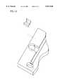
- FIG. 4is a perspective view of a bridgepiece of a preferred embodiment of the present invention.
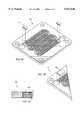
- FIG. 5is a perspective view of the anode side of a bipolar fuel cell plate.
- FIG. 6is a perspective view of the anode side of a bipolar fuel cell plate of the present invention, showing the insertion of the bridgepiece of the present invention into the flow channel.
- FIG. 7Ais a perspective view of the cathode side of a bipolar fuel cell plate having multiple parallel flow channels, showing the insertion of multi-channel bridgepieces of the present invention into the flow channels.
- FIG. 7Bis a perspective view of a multichannel bridgepiece, utilizing channel ribs for central support.
- FIG. 7Cis a cross-sectional view of a multichannel bridgepiece, utilizing channel ribs for central support.
- FIG. 8is an exploded perspective view of a fuel cell stack of the present invention.
- FIGS. 9A-9Care depictions of various embodiments of the bridgepiece and flow plate of the present invention, showing ways in which the geometry of the bridgepiece and flow channel can cause enhanced seating of the bridgepiece.
- FIG. 10depicts a bridgepiece with an orifice.
- FIG. 4depicts a preferred embodiment of a bridgepiece 401 for insertion into a fluid flow plate.
- the top of the bridgepieceis substantially planar in order to provide support for the stack component that rests on top of the bridge--either a gasket, or an inoperative extension of the proton exchange membrane.
- the front of the bridgepieceis substantially curved, to conform to the curvature of the fluid inlet manifold of which the front of the bridgepiece will form a part. If a non-circular manifold hole is used, the front of the bridgepiece should have a matching shape (e.g. straight). As depicted in FIG. 4, the bridgepiece may have multiple legs to support it within the channel, and to prevent deformation over time.
- the bridgepiecemay be made of metal, including for example stainless steel or titanium, or any of various plastics, preferably PVDF or Nylon. Whether metal or plastic, the bridgepiece can readily be formed using various methods known to persons skilled in the art, such as casting, molding, milling or electro-discharge machining (EDM).
- EDMelectro-discharge machining
- FIG. 5depicts an anode fluid flow plate 501 of the present invention.
- the fluid flow channel 505extends all the way to the hydrogen manifold holes 503 and 513.
- the flow channelreceives hydrogen from hydrogen manifold 507, of which manifold hole 503 forms a part.
- manifold hole 509forms a portion of an oxygen inlet manifold
- manifold hole 511forms a portion of a coolant inlet manifold
- manifold holes 513, 515 and 517form portions of outlet manifolds for exhaust gases and water, respectively.
- FIG. 6depicts the insertion of the bridgepieces 601 and 603 into the anode fluid flow plate 605.
- the bridgepiecemay be epoxied or tackwelded in place, or may rely on the stacking pressure of the other plates to keep it in place.
- the bridgepiece and channelare formed with detents and indentations or with unique geometries, such that the bridgepiece will seat within the channel without the need for epoxy or tackwelding.
- FIG. 7Adepicts a preferred embodiment of the insertion of bridgepiece 701 onto a fluid flow plate 703 that forms multiple fluid flow channels.
- FIGS. 7B and 7Cdepict an alternate preferred embodiment of insertion of bridgepiece 705 onto fluid flow plate 707 that forms multiple flow channels.
- the bridgepiecespans multiple channels, and is supported by channel ribs of reduced height.
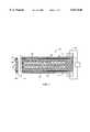
- FIG. 8is an exploded view of a preferred embodiment of a cross section of a fuel cell of the present invention, depicting the interaction of the different components of the fuel cell.
- fuel cell plate 803is a bipolar plate with a hydrogen flow surface on the side facing up (the anode side), and an oxygen flow surface on the side facing down (the cathode side).
- Adjacent fluid flow plate 809is also a bipolar plate with the oxygen flow surface (cathode side) facing down.
- Proton exchange membrane 811is positioned between the two bipolar plates, and on either side of the proton exchange membrane 811 is a gas diffusion layer (not depicted), which facilitates distribution of reactant gas to reaction sites.
- Elastomeric "picture frame” gaskets 805 and 808are positioned between the plates in order to isolate the reactant gases from each other.
- each fuel cell plate and gaskethas holes that align to form the columnar passages that constitute each of the inlet and outlet fluid flow manifolds.
- manifold holes 815align to form the hydrogen inlet manifold
- manifold holes 817align to form the oxygen inlet manifold
- manifold holes 819align to form the coolant inlet manifold
- manifold holes 821align to form the humidification water inlet manifold
- manifold holes 823, 825 and 827align to form the hydrogen, oxygen, and water exhaust manifolds, respectively.
- FIG. 8shows the placement of two different bridgepieces (801 and 807), but it will be recognized that additional bridgepieces could be usefully deployed.
- Bridgepiece 807is positioned in the oxygen inlet of fuel cell plate 809 and supports gasket 808.
- Bridgepiece 801is positioned in the hydrogen inlet of bipolar plate 803 and supports gasket 805. It is readily apparent that without bridgepiece 801 supporting gasket 805, the gasket could droop, allowing flow of H 2 gas over the gasket material. Such leakage could result in (1) leakage of H 2 to the environment, with loss of power output, as well as potentially explosive side-effects, or (2) an unintentional internal reaction with oxygen from the cathode side of the proton exchange membrane. This mixing could result in loss of power output, and also has the potential to cause localized fuel combustion that can be detrimental to the fuel cell itself. In addition to the potential for leakage, the drooping gasket could occlude the flow channel, and in that manner reduce the efficiency of the cell.
- FIGS. 9A-9Cshow bridgepieces and fluid flow plates of alternative preferred embodiments of the present invention. These diagrams depict how different geometries of the bridgepiece and fluid flow plate can be used to enable the bridgepiece to stay in place on the fluid flow plate without the need for epoxy or tackwelding.
- the fluid flow channelwidens prior to the intersection of the fluid flow channel and the fluid inlet manifold.
- the bridgepieceis correspondingly triangular in shape. The widening of the channel thus provides a geometry into which the bridgepiece can easily fit and provides better seating for the bridgepiece.
- FIG. 9Ashow bridgepieces and fluid flow plates of alternative preferred embodiments of the present invention. These diagrams depict how different geometries of the bridgepiece and fluid flow plate can be used to enable the bridgepiece to stay in place on the fluid flow plate without the need for epoxy or tackwelding.
- the fluid flow channelwidens prior to the intersection of the fluid flow channel and the fluid inlet manifold.
- the bridgepieceis correspondingly triang
- the vertical members of the bridgepieceinclude horizontal extensions that fit into a correspondingly widened area at the base of the flow channel.
- the vertical members of the bridgepieceinclude detents that fit into corresponding indentations at the base of the flow channel.
- FIG. 10depicts a bridgepiece having an orifice for precise regulation of humidification fluid flow in a flow channel of a fluid flow plate.
Landscapes
- Life Sciences & Earth Sciences (AREA)
- Engineering & Computer Science (AREA)
- Manufacturing & Machinery (AREA)
- Sustainable Development (AREA)
- Sustainable Energy (AREA)
- Chemical & Material Sciences (AREA)
- Chemical Kinetics & Catalysis (AREA)
- Electrochemistry (AREA)
- General Chemical & Material Sciences (AREA)
- Fuel Cell (AREA)
Abstract
Description
Claims (19)
Priority Applications (3)
| Application Number | Priority Date | Filing Date | Title |
|---|---|---|---|
| US08/839,667US6017648A (en) | 1997-04-15 | 1997-04-15 | Insertable fluid flow passage bridgepiece and method |
| AU66820/98AAU6682098A (en) | 1997-04-15 | 1998-03-04 | Fuel cell fluid flow plate with insertable fluid flow passage bridgepiece |
| PCT/US1998/004174WO1998047197A1 (en) | 1997-04-15 | 1998-03-04 | Fuel cell fluid flow plate with insertable fluid flow passage bridgepiece |
Applications Claiming Priority (1)
| Application Number | Priority Date | Filing Date | Title |
|---|---|---|---|
| US08/839,667US6017648A (en) | 1997-04-15 | 1997-04-15 | Insertable fluid flow passage bridgepiece and method |
Publications (1)
| Publication Number | Publication Date |
|---|---|
| US6017648Atrue US6017648A (en) | 2000-01-25 |
Family
ID=25280358
Family Applications (1)
| Application Number | Title | Priority Date | Filing Date |
|---|---|---|---|
| US08/839,667Expired - LifetimeUS6017648A (en) | 1997-04-15 | 1997-04-15 | Insertable fluid flow passage bridgepiece and method |
Country Status (3)
| Country | Link |
|---|---|
| US (1) | US6017648A (en) |
| AU (1) | AU6682098A (en) |
| WO (1) | WO1998047197A1 (en) |
Cited By (55)
| Publication number | Priority date | Publication date | Assignee | Title |
|---|---|---|---|---|
| US6322919B1 (en)* | 1999-08-16 | 2001-11-27 | Alliedsignal Inc. | Fuel cell and bipolar plate for use with same |
| US6410179B1 (en)* | 2000-04-19 | 2002-06-25 | Plug Power Inc. | Fluid flow plate having a bridge piece |
| US20020172852A1 (en)* | 2001-05-15 | 2002-11-21 | David Frank | Flow field plate for a fuel cell and fuel cell assembly incorporating the flow field plate |
| US6500580B1 (en)* | 1998-10-07 | 2002-12-31 | Plug Power Inc. | Fuel cell fluid flow plate for promoting fluid service |
| US6528198B1 (en)* | 1997-07-23 | 2003-03-04 | Plug Power, Inc. | Fuel cell membrane hydration and fluid metering |
| US20030049514A1 (en)* | 2000-03-22 | 2003-03-13 | Mallant Ronald Karel Antoine Marie | Plate, plate assembly and eletrochemical cell stack |
| US6602626B1 (en)* | 2000-02-16 | 2003-08-05 | Gencell Corporation | Fuel cell with internal thermally integrated autothermal reformer |
| US6620538B2 (en) | 2002-01-23 | 2003-09-16 | Avista Laboratories, Inc. | Method and apparatus for monitoring equivalent series resistance and for shunting a fuel cell |
| US20030186106A1 (en)* | 2001-05-15 | 2003-10-02 | David Frank | Fuel cell flow field plate |
| US6635378B1 (en)* | 1999-08-16 | 2003-10-21 | Hybrid Power Generation System, Llc | Fuel cell having improved condensation and reaction product management capabilities |
| US6689500B2 (en) | 2001-03-29 | 2004-02-10 | Power Plug, Inc. | Cooling a fuel cell stack |
| US6703155B2 (en) | 2001-11-13 | 2004-03-09 | Avista Laboratories, Inc. | Power tap device, fuel cell stack, and method of dividing a fuel cell stack |
| EP1220347A3 (en)* | 2000-12-27 | 2004-05-12 | Matsushita Electric Industrial Co., Ltd. | Polymer electrolyte fuel cell stack |
| US20040115510A1 (en)* | 2002-12-04 | 2004-06-17 | Yang Jefferson Ys | Gastight gasket assembly for gas channels of fuel cell stack |
| US20040197630A1 (en)* | 2003-04-03 | 2004-10-07 | Wilson Mahlon S. | Direct methanol fuel cell stack |
| US20050019646A1 (en)* | 2003-05-16 | 2005-01-27 | Joos Nathaniel Ian | Complementary active-surface feed flow |
| US20050069749A1 (en)* | 2003-08-15 | 2005-03-31 | David Frank | Flow field plate arrangement |
| US20050112436A1 (en)* | 2003-11-25 | 2005-05-26 | Carol Jeffcoate | Methods and devices for heating or cooling fuel cell systems |
| US20050118488A1 (en)* | 2003-09-30 | 2005-06-02 | Kabushiki Kaisha Toshiba | Separator for fuel cell and fuel cell therewith |
| US20050115825A1 (en)* | 2003-09-22 | 2005-06-02 | David Frank | Electrolyzer cell arrangement |
| US20050183948A1 (en)* | 2003-09-22 | 2005-08-25 | Ali Rusta-Sallehy | Apparatus and method for reducing instances of pump de-priming |
| US20050221159A1 (en)* | 2004-03-31 | 2005-10-06 | Kabushiki Kaisha Toshiba | Liquid fuel cell |
| US20050271910A1 (en)* | 2004-06-07 | 2005-12-08 | Hyteon Inc. | Fuel cell stack with even distributing gas manifolds |
| US20050271909A1 (en)* | 2004-06-07 | 2005-12-08 | Hyteon Inc. | Flow field plate for use in fuel cells |
| AU2001290884B2 (en)* | 2000-09-13 | 2005-12-15 | Merck & Co., Inc. | Alpha V integrin receptor antagonists |
| US20060035133A1 (en)* | 2004-08-12 | 2006-02-16 | Rock Jeffrey A | Stamped bridges and plates for reactant delivery for a fuel cell |
| US20060068250A1 (en)* | 2004-09-24 | 2006-03-30 | Dingrong Bai | Integrated fuel cell power module |
| US20060127709A1 (en)* | 2004-12-13 | 2006-06-15 | Dingrong Bai | Fuel cell stack with multiple groups of cells and flow passes |
| EP1324416A3 (en)* | 2001-12-27 | 2006-07-26 | Honda Giken Kogyo Kabushiki Kaisha | Fuel cell stack |
| US20060172177A1 (en)* | 2004-11-24 | 2006-08-03 | Joachim Scherer | Electromagnetic system with a supply plate |
| US20060188763A1 (en)* | 2005-02-22 | 2006-08-24 | Dingrong Bai | Fuel cell system comprising modular design features |
| US20060210855A1 (en)* | 2005-03-15 | 2006-09-21 | David Frank | Flow field plate arrangement |
| US20060210857A1 (en)* | 2005-03-15 | 2006-09-21 | David Frank | Electrochemical cell arrangement with improved mea-coolant manifold isolation |
| US20060292433A1 (en)* | 2005-06-24 | 2006-12-28 | Honda Motor Co., Ltd. | Fuel cell and fuel cell stack |
| US20070207364A1 (en)* | 2006-03-03 | 2007-09-06 | Abd Elhamid Mahmoud H | Fuel cells comprising moldable gaskets, and methods of making |
| US20070275288A1 (en)* | 2006-05-23 | 2007-11-29 | Goebel Steven G | Diffusion media for seal support for improved fuel cell design |
| US20090071819A1 (en)* | 2003-09-22 | 2009-03-19 | Ali Rusta-Sallehy | Electrolyzer cell stack system |
| US20090253022A1 (en)* | 2008-04-08 | 2009-10-08 | Rock Jeffrey A | Seal for pem fuel cell plate |
| US20090291350A1 (en)* | 2008-05-22 | 2009-11-26 | Honda Motor Co., Ltd. | Electrolyte electrode assembly and fuel cell |
| DE102009002889A1 (en) | 2008-11-04 | 2010-05-12 | Industrial Technology Research Institute | Fuel cell fluid flow plate with a sleeve passage piece |
| US7776485B1 (en)* | 2005-08-03 | 2010-08-17 | Hydro Fuel Cell Corporation | Fuel cell stack with a plurality of connected single unit fuel cells |
| US20100330461A1 (en)* | 2009-06-30 | 2010-12-30 | Nok Corporation | Fuel Cell |
| US20110136042A1 (en)* | 2009-12-07 | 2011-06-09 | Chi-Chang Chen | Fluid flow plate assemblies |
| US20110136043A1 (en)* | 2009-12-07 | 2011-06-09 | Chi-Chang Chen | Modularized fuel cell devices and fluid flow plate assemblies |
| US20110136033A1 (en)* | 2009-12-07 | 2011-06-09 | Chi-Chang Chen | Fuel cell devices |
| US20110132477A1 (en)* | 2009-12-07 | 2011-06-09 | Chi-Chang Chen | Fluid flow plate assembly having parallel flow channels |
| US20110177429A1 (en)* | 2010-01-21 | 2011-07-21 | Industrial Technology Research Institute | Fluid flow plate of a fuel cell |
| CN102142566A (en)* | 2010-01-28 | 2011-08-03 | 财团法人工业技术研究院 | Fuel Cell Flow Field Plate |
| US8557482B2 (en) | 2009-12-24 | 2013-10-15 | Industrial Technology Research Institute | Fuel cell fluid flow field plate comprising an upward extending portion and a cover extending portion |
| WO2018111636A1 (en)* | 2016-12-13 | 2018-06-21 | 3M Innovative Properties Company | Monopolar plate-electrode assemblies and electrochemical cells and liquid flow batteries therefrom |
| US10006722B2 (en) | 2015-10-29 | 2018-06-26 | Dana Canada Corporation | Structural support element in heat exchangers |
| WO2020008387A1 (en) | 2018-07-05 | 2020-01-09 | Eh Group Engineering Ag | Fuel cells |
| US10547064B2 (en)* | 2016-10-05 | 2020-01-28 | GM Global Technology Operations LLC | Tunnel cross section for more uniformed contact pressure distribution on metal bead seal at the intersection between bead and tunnel |
| US20200340129A1 (en)* | 2019-04-25 | 2020-10-29 | Shanghai Asclepius Meditec Co., Ltd. | Expanded ion-exchange membrane electrolysis cell |
| CN118867298A (en)* | 2024-07-02 | 2024-10-29 | 西安交通大学 | A fuel cell cathode, bipolar plate structure and design method |
Families Citing this family (1)
| Publication number | Priority date | Publication date | Assignee | Title |
|---|---|---|---|---|
| DE10236997B4 (en)* | 2002-08-13 | 2006-09-14 | Daimlerchrysler Ag | Electrochemical cell stack |
Citations (14)
| Publication number | Priority date | Publication date | Assignee | Title |
|---|---|---|---|---|
| US4403018A (en)* | 1980-05-31 | 1983-09-06 | Electrochemische Energieconversie, N.V. | Apparatus for supplying or draining a fluid to or from the marginal portion of a flat fuel cell electrode and an electrode element and a fuel cell provided with such an apparatus |
| US4590135A (en)* | 1984-05-11 | 1986-05-20 | Occidental Chemical Corporation | Fuel cell structures |
| JPS62147665A (en)* | 1985-12-23 | 1987-07-01 | Hitachi Ltd | Fuel cell |
| JPS63105474A (en)* | 1986-10-21 | 1988-05-10 | Fuji Electric Co Ltd | Fuel cell |
| US4743518A (en)* | 1987-03-04 | 1988-05-10 | International Fuel Cells Corporation | Corrosion resistant fuel cell structure |
| US4818640A (en)* | 1985-09-25 | 1989-04-04 | Kureha Kagaku Kogyo Kabushiki Kaisha | Carbonaceous composite product produced by joining carbonaceous materials together by tetrafluoroethylene resin, and process for producing the same |
| JPH01173576A (en)* | 1987-12-28 | 1989-07-10 | Hitachi Ltd | Fuel cell separator |
| US4945019A (en)* | 1988-09-20 | 1990-07-31 | Globe-Union Inc. | Friction welded battery component |
| US5200278A (en)* | 1991-03-15 | 1993-04-06 | Ballard Power Systems, Inc. | Integrated fuel cell power generation system |
| US5234776A (en)* | 1990-08-03 | 1993-08-10 | Fuji Electric Co., Ltd. | Solid polymer electrolyte fuel cell system with ribbed configuration |
| JPH0689728A (en)* | 1992-09-07 | 1994-03-29 | Mitsubishi Heavy Ind Ltd | Flat plate type solid electrolyte fuel cell |
| US5342706A (en)* | 1989-05-03 | 1994-08-30 | Institute Of Gas Technology | Fully internal manifolded fuel cell stack |
| US5514487A (en)* | 1994-12-27 | 1996-05-07 | Ballard Power Systems Inc. | Edge manifold assembly for an electrochemical fuel cell stack |
| JPH0935726A (en)* | 1995-07-18 | 1997-02-07 | Tanaka Kikinzoku Kogyo Kk | Gas plate for fuel cell, cooling plate and fuel cell |
- 1997
- 1997-04-15USUS08/839,667patent/US6017648A/ennot_activeExpired - Lifetime
- 1998
- 1998-03-04AUAU66820/98Apatent/AU6682098A/ennot_activeAbandoned
- 1998-03-04WOPCT/US1998/004174patent/WO1998047197A1/enactiveApplication Filing
Patent Citations (16)
| Publication number | Priority date | Publication date | Assignee | Title |
|---|---|---|---|---|
| US4403018A (en)* | 1980-05-31 | 1983-09-06 | Electrochemische Energieconversie, N.V. | Apparatus for supplying or draining a fluid to or from the marginal portion of a flat fuel cell electrode and an electrode element and a fuel cell provided with such an apparatus |
| US4590135A (en)* | 1984-05-11 | 1986-05-20 | Occidental Chemical Corporation | Fuel cell structures |
| US4818640A (en)* | 1985-09-25 | 1989-04-04 | Kureha Kagaku Kogyo Kabushiki Kaisha | Carbonaceous composite product produced by joining carbonaceous materials together by tetrafluoroethylene resin, and process for producing the same |
| JPS62147665A (en)* | 1985-12-23 | 1987-07-01 | Hitachi Ltd | Fuel cell |
| JPS63105474A (en)* | 1986-10-21 | 1988-05-10 | Fuji Electric Co Ltd | Fuel cell |
| US4743518A (en)* | 1987-03-04 | 1988-05-10 | International Fuel Cells Corporation | Corrosion resistant fuel cell structure |
| EP0281949A1 (en)* | 1987-03-04 | 1988-09-14 | International Fuel Cells Corporation | Corrosion resistant fuel cell structure |
| JPH01173576A (en)* | 1987-12-28 | 1989-07-10 | Hitachi Ltd | Fuel cell separator |
| US4945019A (en)* | 1988-09-20 | 1990-07-31 | Globe-Union Inc. | Friction welded battery component |
| US5342706A (en)* | 1989-05-03 | 1994-08-30 | Institute Of Gas Technology | Fully internal manifolded fuel cell stack |
| US5234776A (en)* | 1990-08-03 | 1993-08-10 | Fuji Electric Co., Ltd. | Solid polymer electrolyte fuel cell system with ribbed configuration |
| US5200278A (en)* | 1991-03-15 | 1993-04-06 | Ballard Power Systems, Inc. | Integrated fuel cell power generation system |
| JPH0689728A (en)* | 1992-09-07 | 1994-03-29 | Mitsubishi Heavy Ind Ltd | Flat plate type solid electrolyte fuel cell |
| US5514487A (en)* | 1994-12-27 | 1996-05-07 | Ballard Power Systems Inc. | Edge manifold assembly for an electrochemical fuel cell stack |
| WO1996020510A1 (en)* | 1994-12-27 | 1996-07-04 | Ballard Power Systems Inc. | Edge manifold assembly for an electrochemical fuel cell stack |
| JPH0935726A (en)* | 1995-07-18 | 1997-02-07 | Tanaka Kikinzoku Kogyo Kk | Gas plate for fuel cell, cooling plate and fuel cell |
Cited By (92)
| Publication number | Priority date | Publication date | Assignee | Title |
|---|---|---|---|---|
| US6528198B1 (en)* | 1997-07-23 | 2003-03-04 | Plug Power, Inc. | Fuel cell membrane hydration and fluid metering |
| US6500580B1 (en)* | 1998-10-07 | 2002-12-31 | Plug Power Inc. | Fuel cell fluid flow plate for promoting fluid service |
| US6322919B1 (en)* | 1999-08-16 | 2001-11-27 | Alliedsignal Inc. | Fuel cell and bipolar plate for use with same |
| US6635378B1 (en)* | 1999-08-16 | 2003-10-21 | Hybrid Power Generation System, Llc | Fuel cell having improved condensation and reaction product management capabilities |
| US6602626B1 (en)* | 2000-02-16 | 2003-08-05 | Gencell Corporation | Fuel cell with internal thermally integrated autothermal reformer |
| US20030049514A1 (en)* | 2000-03-22 | 2003-03-13 | Mallant Ronald Karel Antoine Marie | Plate, plate assembly and eletrochemical cell stack |
| US6410179B1 (en)* | 2000-04-19 | 2002-06-25 | Plug Power Inc. | Fluid flow plate having a bridge piece |
| AU2001290884B2 (en)* | 2000-09-13 | 2005-12-15 | Merck & Co., Inc. | Alpha V integrin receptor antagonists |
| US7521143B2 (en) | 2000-12-27 | 2009-04-21 | Panasonic Corporation | Polymer electrolyte fuel cell |
| EP1220347A3 (en)* | 2000-12-27 | 2004-05-12 | Matsushita Electric Industrial Co., Ltd. | Polymer electrolyte fuel cell stack |
| US20040209141A1 (en)* | 2000-12-27 | 2004-10-21 | Matsushita Electric Industrial Co., Ltd. | Polymer electrolyte fuel cell |
| US6689500B2 (en) | 2001-03-29 | 2004-02-10 | Power Plug, Inc. | Cooling a fuel cell stack |
| US20030186106A1 (en)* | 2001-05-15 | 2003-10-02 | David Frank | Fuel cell flow field plate |
| US6878477B2 (en)* | 2001-05-15 | 2005-04-12 | Hydrogenics Corporation | Fuel cell flow field plate |
| US20020172852A1 (en)* | 2001-05-15 | 2002-11-21 | David Frank | Flow field plate for a fuel cell and fuel cell assembly incorporating the flow field plate |
| US20050064272A1 (en)* | 2001-05-15 | 2005-03-24 | Hydrogenics Corporation | Fuel cell flow field plate |
| US6703155B2 (en) | 2001-11-13 | 2004-03-09 | Avista Laboratories, Inc. | Power tap device, fuel cell stack, and method of dividing a fuel cell stack |
| EP1324416A3 (en)* | 2001-12-27 | 2006-07-26 | Honda Giken Kogyo Kabushiki Kaisha | Fuel cell stack |
| US6620538B2 (en) | 2002-01-23 | 2003-09-16 | Avista Laboratories, Inc. | Method and apparatus for monitoring equivalent series resistance and for shunting a fuel cell |
| US6811906B2 (en) | 2002-01-23 | 2004-11-02 | Relion, Inc. | Method and apparatus for monitoring equivalent series resistance and for shunting a fuel cell |
| US6805987B2 (en) | 2002-01-23 | 2004-10-19 | Relion, Inc. | Method and apparatus for monitoring equivalent series resistance and for shunting a fuel cell |
| US20030203249A1 (en)* | 2002-01-23 | 2003-10-30 | Lijun Bai | Method and apparatus for monitoring equivalent series resistance and for shunting a fuel cell |
| US20030203254A1 (en)* | 2002-01-23 | 2003-10-30 | Lijun Bai | Method and apparatus for monitoring equivalent series resistance and for shunting a fuel cell |
| US7049017B2 (en) | 2002-01-23 | 2006-05-23 | Relion, Inc. | Method and apparatus for monitoring equivalent series resistance and for shunting a fuel cell |
| US6982129B1 (en) | 2002-01-23 | 2006-01-03 | Relion, Inc. | Method and apparatus for monitoring equivalent series resistance and for shunting a fuel cell |
| US20040115510A1 (en)* | 2002-12-04 | 2004-06-17 | Yang Jefferson Ys | Gastight gasket assembly for gas channels of fuel cell stack |
| WO2004095619A3 (en)* | 2003-04-03 | 2004-12-16 | Univ California | Improved direct methanol fuel cell stack |
| US6864004B2 (en)* | 2003-04-03 | 2005-03-08 | The Regents Of The University Of California | Direct methanol fuel cell stack |
| US20040197630A1 (en)* | 2003-04-03 | 2004-10-07 | Wilson Mahlon S. | Direct methanol fuel cell stack |
| US20050019646A1 (en)* | 2003-05-16 | 2005-01-27 | Joos Nathaniel Ian | Complementary active-surface feed flow |
| US20050031936A1 (en)* | 2003-05-16 | 2005-02-10 | Joos Nathaniel Ian | Symmetrical flow field plates |
| US20050069749A1 (en)* | 2003-08-15 | 2005-03-31 | David Frank | Flow field plate arrangement |
| US8419910B2 (en) | 2003-09-22 | 2013-04-16 | Hydrogenics Corporation | Electrolyzer cell stack system |
| US20050115825A1 (en)* | 2003-09-22 | 2005-06-02 | David Frank | Electrolyzer cell arrangement |
| US20090071819A1 (en)* | 2003-09-22 | 2009-03-19 | Ali Rusta-Sallehy | Electrolyzer cell stack system |
| US7353085B2 (en) | 2003-09-22 | 2008-04-01 | Hydrogenics Corporation | Electrolyzer cell stack system |
| US20050197743A1 (en)* | 2003-09-22 | 2005-09-08 | Ali Rusta-Sallehy | Electrolyzer cell stack system |
| US20050183948A1 (en)* | 2003-09-22 | 2005-08-25 | Ali Rusta-Sallehy | Apparatus and method for reducing instances of pump de-priming |
| US9580825B2 (en) | 2003-09-22 | 2017-02-28 | Hydrogenics Corporation | Electrolyzer cell stack system |
| US20050260482A1 (en)* | 2003-09-22 | 2005-11-24 | David Frank | Flow field plate arrangement |
| US20050118488A1 (en)* | 2003-09-30 | 2005-06-02 | Kabushiki Kaisha Toshiba | Separator for fuel cell and fuel cell therewith |
| US20050112436A1 (en)* | 2003-11-25 | 2005-05-26 | Carol Jeffcoate | Methods and devices for heating or cooling fuel cell systems |
| US20050221159A1 (en)* | 2004-03-31 | 2005-10-06 | Kabushiki Kaisha Toshiba | Liquid fuel cell |
| US7531264B2 (en) | 2004-06-07 | 2009-05-12 | Hyteon Inc. | Fuel cell stack with even distributing gas manifolds |
| US7524575B2 (en) | 2004-06-07 | 2009-04-28 | Hyteon Inc. | Flow field plate for use in fuel cells |
| US20050271909A1 (en)* | 2004-06-07 | 2005-12-08 | Hyteon Inc. | Flow field plate for use in fuel cells |
| US20050271910A1 (en)* | 2004-06-07 | 2005-12-08 | Hyteon Inc. | Fuel cell stack with even distributing gas manifolds |
| US20060035133A1 (en)* | 2004-08-12 | 2006-02-16 | Rock Jeffrey A | Stamped bridges and plates for reactant delivery for a fuel cell |
| US7318973B2 (en) | 2004-08-12 | 2008-01-15 | General Motors Corporation | Stamped bridges and plates for reactant delivery for a fuel cell |
| US20060068250A1 (en)* | 2004-09-24 | 2006-03-30 | Dingrong Bai | Integrated fuel cell power module |
| US7314680B2 (en) | 2004-09-24 | 2008-01-01 | Hyteon Inc | Integrated fuel cell power module |
| US20060172177A1 (en)* | 2004-11-24 | 2006-08-03 | Joachim Scherer | Electromagnetic system with a supply plate |
| US20060127709A1 (en)* | 2004-12-13 | 2006-06-15 | Dingrong Bai | Fuel cell stack with multiple groups of cells and flow passes |
| US7479333B2 (en) | 2004-12-13 | 2009-01-20 | Hyteon, Inc. | Fuel cell stack with multiple groups of cells and flow passes |
| US20060188763A1 (en)* | 2005-02-22 | 2006-08-24 | Dingrong Bai | Fuel cell system comprising modular design features |
| US20060210857A1 (en)* | 2005-03-15 | 2006-09-21 | David Frank | Electrochemical cell arrangement with improved mea-coolant manifold isolation |
| US20060210855A1 (en)* | 2005-03-15 | 2006-09-21 | David Frank | Flow field plate arrangement |
| US20060292433A1 (en)* | 2005-06-24 | 2006-12-28 | Honda Motor Co., Ltd. | Fuel cell and fuel cell stack |
| US7776485B1 (en)* | 2005-08-03 | 2010-08-17 | Hydro Fuel Cell Corporation | Fuel cell stack with a plurality of connected single unit fuel cells |
| US20070207364A1 (en)* | 2006-03-03 | 2007-09-06 | Abd Elhamid Mahmoud H | Fuel cells comprising moldable gaskets, and methods of making |
| US20070275288A1 (en)* | 2006-05-23 | 2007-11-29 | Goebel Steven G | Diffusion media for seal support for improved fuel cell design |
| US7972741B2 (en) | 2006-05-23 | 2011-07-05 | GM Global Technology Operations LLC | Diffusion media for seal support for improved fuel cell design |
| US8211585B2 (en) | 2008-04-08 | 2012-07-03 | GM Global Technology Operations LLC | Seal for PEM fuel cell plate |
| US20090253022A1 (en)* | 2008-04-08 | 2009-10-08 | Rock Jeffrey A | Seal for pem fuel cell plate |
| US20090291350A1 (en)* | 2008-05-22 | 2009-11-26 | Honda Motor Co., Ltd. | Electrolyte electrode assembly and fuel cell |
| US8524416B2 (en)* | 2008-05-22 | 2013-09-03 | Honda Motor Co., Ltd. | Electrolyte electrode assembly and fuel cell |
| DE102009002889A1 (en) | 2008-11-04 | 2010-05-12 | Industrial Technology Research Institute | Fuel cell fluid flow plate with a sleeve passage piece |
| US20100124690A1 (en)* | 2008-11-04 | 2010-05-20 | Industrial Technology Research Institute | Fuel cell fluid flow plate with shell passageway piece |
| US8263284B2 (en) | 2008-11-04 | 2012-09-11 | Industrial Technology Research Institute | Fuel cell fluid flow plate with shell passageway piece |
| US8329355B2 (en)* | 2009-06-30 | 2012-12-11 | Nok Corporation | Fuel cell separator and gas diffusion layer |
| US20100330461A1 (en)* | 2009-06-30 | 2010-12-30 | Nok Corporation | Fuel Cell |
| US8691473B2 (en) | 2009-12-07 | 2014-04-08 | Industrial Technology Research Institute | Fuel cell module having non-planar component surface |
| US8828621B2 (en) | 2009-12-07 | 2014-09-09 | Industrial Technology Research Institute | Modularized fuel cell devices and fluid flow plate assemblies |
| US20110132477A1 (en)* | 2009-12-07 | 2011-06-09 | Chi-Chang Chen | Fluid flow plate assembly having parallel flow channels |
| US20110136033A1 (en)* | 2009-12-07 | 2011-06-09 | Chi-Chang Chen | Fuel cell devices |
| US20110136043A1 (en)* | 2009-12-07 | 2011-06-09 | Chi-Chang Chen | Modularized fuel cell devices and fluid flow plate assemblies |
| US20110136042A1 (en)* | 2009-12-07 | 2011-06-09 | Chi-Chang Chen | Fluid flow plate assemblies |
| US8691475B2 (en) | 2009-12-24 | 2014-04-08 | Industrial Technology Research Institute | Method for forming fuel cell fluid flow field plate |
| US8557482B2 (en) | 2009-12-24 | 2013-10-15 | Industrial Technology Research Institute | Fuel cell fluid flow field plate comprising an upward extending portion and a cover extending portion |
| DE102010020159A1 (en)* | 2010-01-21 | 2011-07-28 | Industrial Technology Research Institute, Hsinchu | Fluid flow plate of a fuel cell |
| US20110177429A1 (en)* | 2010-01-21 | 2011-07-21 | Industrial Technology Research Institute | Fluid flow plate of a fuel cell |
| DE102010020159B4 (en)* | 2010-01-21 | 2015-12-03 | Industrial Technology Research Institute | Fluid flow plate of a fuel cell |
| US8652708B2 (en) | 2010-01-21 | 2014-02-18 | Industrial Technology Research Institute | Fluid flow plate with a supporting frame for a fuel cell |
| CN102142566A (en)* | 2010-01-28 | 2011-08-03 | 财团法人工业技术研究院 | Fuel Cell Flow Field Plate |
| US10006722B2 (en) | 2015-10-29 | 2018-06-26 | Dana Canada Corporation | Structural support element in heat exchangers |
| US10547064B2 (en)* | 2016-10-05 | 2020-01-28 | GM Global Technology Operations LLC | Tunnel cross section for more uniformed contact pressure distribution on metal bead seal at the intersection between bead and tunnel |
| WO2018111636A1 (en)* | 2016-12-13 | 2018-06-21 | 3M Innovative Properties Company | Monopolar plate-electrode assemblies and electrochemical cells and liquid flow batteries therefrom |
| WO2020008387A1 (en) | 2018-07-05 | 2020-01-09 | Eh Group Engineering Ag | Fuel cells |
| US12148965B2 (en) | 2018-07-05 | 2024-11-19 | Eh Group Engineering Sa | Fuel cells |
| US20200340129A1 (en)* | 2019-04-25 | 2020-10-29 | Shanghai Asclepius Meditec Co., Ltd. | Expanded ion-exchange membrane electrolysis cell |
| US11879180B2 (en)* | 2019-04-25 | 2024-01-23 | Shanghai Asclepius Meditec Co., Ltd. | Expanded ion-exchange membrane electrolysis cell |
| CN118867298A (en)* | 2024-07-02 | 2024-10-29 | 西安交通大学 | A fuel cell cathode, bipolar plate structure and design method |
Also Published As
| Publication number | Publication date |
|---|---|
| WO1998047197A1 (en) | 1998-10-22 |
| AU6682098A (en) | 1998-11-11 |
Similar Documents
| Publication | Publication Date | Title |
|---|---|---|
| US6017648A (en) | Insertable fluid flow passage bridgepiece and method | |
| US7081316B2 (en) | Bipolar plate assembly having transverse legs | |
| US6858338B2 (en) | Solid polymer electrolyte fuel cell assembly, fuel cell stack, and method of supplying reaction gas in fuel cell | |
| US6878477B2 (en) | Fuel cell flow field plate | |
| US7799482B2 (en) | Stack of generators and fuel cell system having the same | |
| JP5416588B2 (en) | Fuel cell stack | |
| US7432008B2 (en) | Gas diffusion layer for an electrochemical cell | |
| WO2001015257A2 (en) | Combined fuel cell flow plate and gas diffusion layer | |
| EP1403951A2 (en) | Fuel cell seals | |
| US20040106028A1 (en) | Fuel cell | |
| JP4921469B2 (en) | PEM fuel cell with filling chamber | |
| US7122273B2 (en) | Light bipolar plate for fuel cell and method for making same | |
| KR100778634B1 (en) | Fuel Cell, Fuel Cell Separator and Fuel Cell Stack Having Same | |
| CN101432914B (en) | Stamped PEM fuel cell plate manufacturing | |
| EP1269556B1 (en) | Plate, plate assembly and electrochemical cell stack | |
| US8053125B2 (en) | Fuel cell having buffer and seal for coolant | |
| KR20110068205A (en) | Fuel cell stack and fuel cell system having same | |
| US10020530B2 (en) | Fuel cell | |
| US20030170528A1 (en) | Moldable separator plate for electrochemical devices and cells | |
| US20090142646A1 (en) | Direct methanol fuel cell stack including flow restrictor and direct methanol fuel cell including the same | |
| JP2007018813A (en) | Fuel cell stack | |
| KR20220033785A (en) | Fuel cell | |
| US7691516B2 (en) | Fuel cell system and stack used therein | |
| US20240079609A1 (en) | Separator for fuel cell | |
| US7691520B2 (en) | Fuel cell system |
Legal Events
| Date | Code | Title | Description |
|---|---|---|---|
| AS | Assignment | Owner name:PLUG POWER, L.L.C., NEW YORK Free format text:ASSIGNMENT OF ASSIGNORS INTEREST;ASSIGNOR:MECHANICAL TECHNOLOGY INCORPORATED;REEL/FRAME:008610/0621 Effective date:19970626 | |
| AS | Assignment | Owner name:PLUG POWER, L.L.C., NEW YORK Free format text:ASSIGNMENT OF ASSIGNORS INTEREST;ASSIGNOR:MECHANICAL TECHNOLOGY INCORPORATED;REEL/FRAME:008899/0020 Effective date:19970626 | |
| AS | Assignment | Owner name:PLUG POWER, L.L.C., NEW YORK Free format text:ASSIGNMENT OF ASSIGNORS INTEREST;ASSIGNOR:JONES, DANIEL O.;REEL/FRAME:008774/0392 Effective date:19971105 | |
| AS | Assignment | Owner name:ENERGY, UNITED STATES DEPARTMNET OF, DISTRICT OF C Free format text:CONFIRMATORY LICENSE;ASSIGNOR:PLUG POWER, L.L.C.;REEL/FRAME:010341/0815 Effective date:19980331 | |
| FEPP | Fee payment procedure | Free format text:PAYOR NUMBER ASSIGNED (ORIGINAL EVENT CODE: ASPN); ENTITY STATUS OF PATENT OWNER: SMALL ENTITY | |
| AS | Assignment | Owner name:PLUG POWER INC., NEW YORK Free format text:MERGER;ASSIGNOR:PLUG POWER, LLC;REEL/FRAME:010453/0449 Effective date:19991101 | |
| STCF | Information on status: patent grant | Free format text:PATENTED CASE | |
| CC | Certificate of correction | ||
| FEPP | Fee payment procedure | Free format text:PAT HOLDER CLAIMS SMALL ENTITY STATUS, ENTITY STATUS SET TO SMALL (ORIGINAL EVENT CODE: LTOS); ENTITY STATUS OF PATENT OWNER: SMALL ENTITY | |
| FPAY | Fee payment | Year of fee payment:4 | |
| REMI | Maintenance fee reminder mailed | ||
| FPAY | Fee payment | Year of fee payment:8 | |
| FPAY | Fee payment | Year of fee payment:12 | |
| AS | Assignment | Owner name:GENERATE LENDING, LLC, CALIFORNIA Free format text:SECURITY INTEREST;ASSIGNOR:PLUG POWER INC.;REEL/FRAME:038463/0132 Effective date:20160321 | |
| AS | Assignment | Owner name:PLUG POWER INC., NEW YORK Free format text:RELEASE BY SECURED PARTY;ASSIGNOR:GENERATE LENDING, LLC;REEL/FRAME:039173/0300 Effective date:20160627 | |
| AS | Assignment | Owner name:HERCULES CAPITAL, INC., CALIFORNIA Free format text:INTELLECTUAL PROPERTY SECURITY AGREEMENT;ASSIGNOR:PLUG POWER INC.;REEL/FRAME:039646/0065 Effective date:20160627 | |
| AS | Assignment | Owner name:EMERGING POWER INC., NEW YORK Free format text:RELEASE BY SECURED PARTY;ASSIGNOR:HERCULES CAPITAL, INC., AS AGENT;REEL/FRAME:041180/0709 Effective date:20161222 Owner name:EMERGENT POWER INC., WASHINGTON Free format text:RELEASE BY SECURED PARTY;ASSIGNOR:HERCULES CAPITAL, INC., AS AGENT;REEL/FRAME:041180/0709 Effective date:20161222 Owner name:PLUG POWER INC., NEW YORK Free format text:RELEASE BY SECURED PARTY;ASSIGNOR:HERCULES CAPITAL, INC., AS AGENT;REEL/FRAME:041180/0709 Effective date:20161222 | |
| AS | Assignment | Owner name:NY GREEN BANK, NEW YORK Free format text:SECURITY INTEREST;ASSIGNOR:PLUG POWER INC.;REEL/FRAME:041200/0623 Effective date:20161223 | |
| AS | Assignment | Owner name:EMERGING POWER INC., NEW YORK Free format text:RELEASE BY SECURED PARTY;ASSIGNOR:NY GREEN BANK, A DIVISION OF THE NEW YORK STATE ENERGY RESEARCH AND DEVELOPMENT AUTHORITY;REEL/FRAME:048751/0844 Effective date:20190329 Owner name:EMERGENT POWER INC., WASHINGTON Free format text:RELEASE BY SECURED PARTY;ASSIGNOR:NY GREEN BANK, A DIVISION OF THE NEW YORK STATE ENERGY RESEARCH AND DEVELOPMENT AUTHORITY;REEL/FRAME:048751/0844 Effective date:20190329 Owner name:PLUG POWER INC, NEW YORK Free format text:RELEASE BY SECURED PARTY;ASSIGNOR:NY GREEN BANK, A DIVISION OF THE NEW YORK STATE ENERGY RESEARCH AND DEVELOPMENT AUTHORITY;REEL/FRAME:048751/0844 Effective date:20190329 |