US6017349A - Transport and processing apparatus for a two-component material - Google Patents
Transport and processing apparatus for a two-component materialDownload PDFInfo
- Publication number
- US6017349A US6017349AUS09/082,849US8284998AUS6017349AUS 6017349 AUS6017349 AUS 6017349AUS 8284998 AUS8284998 AUS 8284998AUS 6017349 AUS6017349 AUS 6017349A
- Authority
- US
- United States
- Prior art keywords
- container
- liquid component
- transport chamber
- piston
- component
- Prior art date
- Legal status (The legal status is an assumption and is not a legal conclusion. Google has not performed a legal analysis and makes no representation as to the accuracy of the status listed.)
- Expired - Lifetime
Links
Images


Classifications
- A—HUMAN NECESSITIES
- A61—MEDICAL OR VETERINARY SCIENCE; HYGIENE
- A61B—DIAGNOSIS; SURGERY; IDENTIFICATION
- A61B17/00—Surgical instruments, devices or methods
- A61B17/56—Surgical instruments or methods for treatment of bones or joints; Devices specially adapted therefor
- A61B17/58—Surgical instruments or methods for treatment of bones or joints; Devices specially adapted therefor for osteosynthesis, e.g. bone plates, screws or setting implements
- A61B17/88—Osteosynthesis instruments; Methods or means for implanting or extracting internal or external fixation devices
- A61B17/8802—Equipment for handling bone cement or other fluid fillers
- A61B17/8805—Equipment for handling bone cement or other fluid fillers for introducing fluid filler into bone or extracting it
- A61B17/8827—Equipment for handling bone cement or other fluid fillers for introducing fluid filler into bone or extracting it with filtering, degassing, venting or pressure relief means
- B—PERFORMING OPERATIONS; TRANSPORTING
- B01—PHYSICAL OR CHEMICAL PROCESSES OR APPARATUS IN GENERAL
- B01F—MIXING, e.g. DISSOLVING, EMULSIFYING OR DISPERSING
- B01F31/00—Mixers with shaking, oscillating, or vibrating mechanisms
- B01F31/40—Mixers with shaking, oscillating, or vibrating mechanisms with an axially oscillating rotary stirrer
- B—PERFORMING OPERATIONS; TRANSPORTING
- B01—PHYSICAL OR CHEMICAL PROCESSES OR APPARATUS IN GENERAL
- B01F—MIXING, e.g. DISSOLVING, EMULSIFYING OR DISPERSING
- B01F33/00—Other mixers; Mixing plants; Combinations of mixers
- B01F33/50—Movable or transportable mixing devices or plants
- B01F33/501—Movable mixing devices, i.e. readily shifted or displaced from one place to another, e.g. portable during use
- B01F33/5011—Movable mixing devices, i.e. readily shifted or displaced from one place to another, e.g. portable during use portable during use, e.g. hand-held
- B01F33/50112—Movable mixing devices, i.e. readily shifted or displaced from one place to another, e.g. portable during use portable during use, e.g. hand-held of the syringe or cartridge type
- B—PERFORMING OPERATIONS; TRANSPORTING
- B01—PHYSICAL OR CHEMICAL PROCESSES OR APPARATUS IN GENERAL
- B01F—MIXING, e.g. DISSOLVING, EMULSIFYING OR DISPERSING
- B01F35/00—Accessories for mixers; Auxiliary operations or auxiliary devices; Parts or details of general application
- B01F35/30—Driving arrangements; Transmissions; Couplings; Brakes
- B01F35/32—Driving arrangements
- B01F35/32005—Type of drive
- B01F35/3202—Hand driven
- B—PERFORMING OPERATIONS; TRANSPORTING
- B01—PHYSICAL OR CHEMICAL PROCESSES OR APPARATUS IN GENERAL
- B01F—MIXING, e.g. DISSOLVING, EMULSIFYING OR DISPERSING
- B01F35/00—Accessories for mixers; Auxiliary operations or auxiliary devices; Parts or details of general application
- B01F35/71—Feed mechanisms
- B01F35/713—Feed mechanisms comprising breaking packages or parts thereof, e.g. piercing or opening sealing elements between compartments or cartridges
- B01F35/7131—Breaking or perforating packages, containers or vials
- B—PERFORMING OPERATIONS; TRANSPORTING
- B01—PHYSICAL OR CHEMICAL PROCESSES OR APPARATUS IN GENERAL
- B01F—MIXING, e.g. DISSOLVING, EMULSIFYING OR DISPERSING
- B01F35/00—Accessories for mixers; Auxiliary operations or auxiliary devices; Parts or details of general application
- B01F35/71—Feed mechanisms
- B01F35/716—Feed mechanisms characterised by the relative arrangement of the containers for feeding or mixing the components
- B01F35/7162—A container being placed inside the other before contacting the contents
- B—PERFORMING OPERATIONS; TRANSPORTING
- B01—PHYSICAL OR CHEMICAL PROCESSES OR APPARATUS IN GENERAL
- B01F—MIXING, e.g. DISSOLVING, EMULSIFYING OR DISPERSING
- B01F35/00—Accessories for mixers; Auxiliary operations or auxiliary devices; Parts or details of general application
- B01F35/75—Discharge mechanisms
- B01F35/754—Discharge mechanisms characterised by the means for discharging the components from the mixer
- B01F35/75425—Discharge mechanisms characterised by the means for discharging the components from the mixer using pistons or plungers
- B01F35/754251—Discharge mechanisms characterised by the means for discharging the components from the mixer using pistons or plungers reciprocating in the mixing receptacle
- A—HUMAN NECESSITIES
- A61—MEDICAL OR VETERINARY SCIENCE; HYGIENE
- A61F—FILTERS IMPLANTABLE INTO BLOOD VESSELS; PROSTHESES; DEVICES PROVIDING PATENCY TO, OR PREVENTING COLLAPSING OF, TUBULAR STRUCTURES OF THE BODY, e.g. STENTS; ORTHOPAEDIC, NURSING OR CONTRACEPTIVE DEVICES; FOMENTATION; TREATMENT OR PROTECTION OF EYES OR EARS; BANDAGES, DRESSINGS OR ABSORBENT PADS; FIRST-AID KITS
- A61F2250/00—Special features of prostheses classified in groups A61F2/00 - A61F2/26 or A61F2/82 or A61F9/00 or A61F11/00 or subgroups thereof
- A61F2250/0058—Additional features; Implant or prostheses properties not otherwise provided for
- A61F2250/0071—Additional features; Implant or prostheses properties not otherwise provided for breakable or frangible
- B—PERFORMING OPERATIONS; TRANSPORTING
- B01—PHYSICAL OR CHEMICAL PROCESSES OR APPARATUS IN GENERAL
- B01F—MIXING, e.g. DISSOLVING, EMULSIFYING OR DISPERSING
- B01F2101/00—Mixing characterised by the nature of the mixed materials or by the application field
- B01F2101/20—Mixing of ingredients for bone cement
- B—PERFORMING OPERATIONS; TRANSPORTING
- B01—PHYSICAL OR CHEMICAL PROCESSES OR APPARATUS IN GENERAL
- B01F—MIXING, e.g. DISSOLVING, EMULSIFYING OR DISPERSING
- B01F33/00—Other mixers; Mixing plants; Combinations of mixers
- B01F33/50—Movable or transportable mixing devices or plants
- B01F33/501—Movable mixing devices, i.e. readily shifted or displaced from one place to another, e.g. portable during use
- B01F33/5011—Movable mixing devices, i.e. readily shifted or displaced from one place to another, e.g. portable during use portable during use, e.g. hand-held
Definitions
- the inventionrelates to a transport and processing apparatus for a two-component material, in particular for bone cement, with a liquid component and a powder component which are separated by a membrane and which each occupy a transport chamber in a closeable container which has an expulsion piston at one end and an opening for the expulsion of mixed two-component material at the opposite end and which encloses a perforated mixing piston.
- a separating pistonwhich separates the powdery region from the region of the liquid component, is arranged between an expulsion piston and a mixing piston.
- the mixing cylinderis assembled of two separate transport cylinders which can be assembled via a rapid coupling. This has the disadvantage that during their actuation the mixing piston, the separating piston and the expulsion piston must operate across a joint between the transport cylinders, which represents a discontinuity.
- This objectis attained by giving the transport chamber for the liquid component a ring shape with a central aperture and with a membrane; by expelling mixed two-component material through the central aperture and the opening; and by destroying the membrane by a relative movement between the transport chamber for the liquid component and a solid body enclosed in the container in order to effect a flow of the liquid component into the transport chamber for the powder component.
- An advantage of this apparatusis that it can be executed without rubber-like soft seals in the form of O-rings or lips. This enables the apparatus to be manufactured of injection molded plastic parts with the exception of a membrane. Furthermore, no collapsed transport containers need be moved along by the expulsion piston during the expulsion of the mixture.
- a further advantage of this apparatusis that preassembled injection molded plastic parts can be delivered to a filling establishment and that final assembly, welding in and, where required, sterilization are possible along with the filling. Independently of the transport and storage, filled quantities arrive directly at the place of work along with the apparatus, which is ready for use.
- the apparatuscan be actuated from the outside for the mixing and expulsion of the two components. The inner space can remain closed off until the expulsion.
- the transport chamber for the liquid componentcan be manufactured in a simple injection molding tool and an attacking force for the destruction of the membrane is effective everywhere on the cross-section of the transport chamber.
- a filling aperture at the transport chamber for the liquid componentwhich can be closed off from the outside enables the liquid component and the powder component to be filled in in the same vertical position of the container.
- the movement of the mixing piston during mixingcan be used for the destruction of the membrane.
- a displacement member which penetrates into the transport chamber for the liquid componenthas the advantage that the liquid component is expelled necessarily and independently of the force of gravity.
- the displacement membercan be provided with a cutting edge and can thus destroy the membrane at the beginning of the relative movement between the displacement member and the transport chamber. If the displacement member and the transport chamber also mutually bind with one another at the end of the expulsion movement, this process becomes irreversible and there is no danger of differently mixed portions of the product being thrust back into the transport chamber for the liquid component.
- a hollow piston rod for the mixing pistonwhich has a closure reaching up to the piston, the piston rod can be used as an outlet tube without dead spaces with unequal mixing arising.
- Forming the transport chamber for the liquid component as a ring chamberalso makes it possible to integrate the transport chamber into a container cover which is axially movable with respect to the container in order to destroy the membrane at a cutting edge of fixed location in the container and in order to allow the liquid component to flow into the transport chamber for the powder component lying beneath it under the action of gravity.
- Advantageous in this arrangementis a lead-off ring, via which the liquid component flows off, and a draw ring, which latches with the container cover when the latter is first lowered and frees an outflow cross-section when the container cover is lifted.
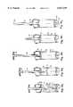
- FIG. 1is a schematic longitudinal section through a filled transport and processing apparatus in which the transport chamber for the liquid component is integrated into the container cover and which has a displacement member;
- FIG. 2shows the transport chamber for the liquid component with an inwardly moved and blocked displacement member after the mixing, shown schematically in the longitudinal section of FIG. 1;
- FIG. 3is a schematic longitudinal section of a filled transport and processing apparatus in which a displacement member is integrated into the container cover, while the transport chamber for the liquid component is fixed in the container as a separate vessel in a transport position;
- FIG. 4is the inwardly moved and blocked transport chamber for the liquid component after the mixing shown schematically in the longitudinal section of FIG. 3;
- FIG. 5is a schematic longitudinal section of an arrangement analogous to FIG. 1 in which a mixing piston can be actuated by a piston rod through the expulsion piston;
- FIG. 6is the arrangement of FIG. 5 in a schematic longitudinal section after the mixing
- FIGS. 7a, b, cshow the filling of the liquid component and of the powder component in an arrangement in accordance with FIG. 5;
- FIG. 7dis a schematic longitudinal section of an arrangement in accordance with FIG. 5 which is filled and ready for use;
- FIG. 7eis a schematic longitudinal section in accordance with FIG. 5 of the bringing together of the liquid component and the powder component;
- FIG. 7fis a schematic longitudinal section in accordance with FIG. 5 of the mixing of the two components
- FIG. 7gis a schematic longitudinal section in accordance with FIG. 5 of the release of the piston rod from the mixing piston;
- FIG. 7his a schematic longitudinal section in accordance with FIG. 5 of the extraction of the vapors from the container by suction;
- FIG. 7iis a schematic longitudinal section in accordance with FIG. 5 of the mixture, which is ready to be expelled, in the container;
- FIG. 8is a schematic longitudinal section of a transport and mixing apparatus with an axially movable cover, which contains the liquid component, in the transport position;
- FIG. 9a schematic longitudinal section of the apparatus of FIG. 8 after the mixing of the components, with the piston rod already having been removed from the mixing piston and an expulsion tube having been put on in its place;
- FIGS. 10a, b, care schematic longitudinal sections of the filling of the components into an apparatus in accordance with FIG. 8;
- FIG. 10dis a schematic longitudinal section of an apparatus in accordance with FIG. 8 which is ready for use.
- FIGS. 10e, f, g, h, i, jshow the bringing together and mixing of the components, the extraction of solvent vapors by suction, and an apparatus, which is ready for expulsion, with an expulsion tube pushed on, shown schematically in the longitudinal section of FIG. 8;
- the figuresshow transport and processing apparatuses for a two-component material, in particular for bone cement, having a liquid component and a powder component which are separated by a membrane, and each occupy a transport chamber in a closeable container which has an expulsion piston at the one end and an opening for the expulsion of mixed two-component material at the opposite end.
- the transport chamber for the liquid componentBy giving the transport chamber for the liquid component a ring shape with a central aperture, the mixed two-component material can be expelled through the aperture.
- the membraneis destroyed by a relative movement between the transport chamber for the liquid component and a solid body enclosed in the container in order to effect a flow of the liquid component into the transport chamber for the powder component and to enable the mixing with a mixing piston.
- the transport containerconsists of an actual container 6 and a container cover 7 which is designed as a transport chamber 4 for the liquid component 1, which has the shape of a ring and which is closed off by a membrane 3 in the form of a circular ring film or foil 16.
- the filling with the liquid component 1 and the sealing off of the transport chamber 4 with the film 16are done in a preparatory operation.
- the following stepsare taken:
- the expulsion piston 8is pressed in to the cylindrical container 6 and fixed with a snap connection 30;
- the powder component 2is filled in;
- the displacement member 12is inserted into the container 6 and latched, with the displacement member 12 having a cover 24 with two guide lips 25a, b which hold back the powder component 2;
- a closure 14 in the form of an outwardly bulging knobis inserted into the piston rod and the container 6 is closed, with only a vacuum extraction opening 21 not yet being closed off.
- the apparatusis ready for use for the mixing of the two components.
- the apparatusIn the case of bone cement the apparatus is welded into a film for transport and storage and sterilized with ⁇ -rays or a gas, e.g. ethylene oxide, or formaldehyde.
- the parts of the apparatusare executed as injection molded parts of plastic and are transparent in order to be able to monitor the mixing at a later time.
- the sterilizationis done either prior to filling using ⁇ -rays or afterwards using gas in order that the liquid is not damaged by ⁇ -rays.
- the apparatusIn the case of bone cement, the apparatus is brought into the operating room in a sterile condition. For mixing the following steps are taken:
- the mixing piston 11 with the piston rod 10is pulled out of a transport securing device 22 and through the powder component 2, with the flowable powder flowing past the mixing piston 11 through slits 29;
- the displacement member 12 with its cutting edge 17is torn by the mixing piston 11 out of its snap connection 20 and pressed into the transport chamber 4 of the liquid component, with the cutting edge 17 tearing open the film 16 and the displacement member 12 completely displacing the liquid component 1 into the transport chamber 5 for the powder component;
- the displacement member 12binds in its final position (FIG. 2) in the transport chamber 5 of the liquid component 1 so that only the components 1, 2 and the mixing piston 11 are still mutually movable;
- the mixing pistonis thrust up and down by a predetermined number of strokes, for example 30 strokes, while being rotated in order to achieve a thorough mixing of the components 1, 2;
- a vacuumis applied for a limited time to the vacuum extraction opening in order to suck off vapors and rising air bubbles;
- the closure 14is removed, the mixing piston 11 is held in an upper position and a forward thrust apparatus with a thrust rod is set onto a bayonet connection 31 in order to be able to expel the finished mixture 18 through the hollow piston rod 10 with the expulsion piston 8.
- the closure plug 14 and its hand gripcan be unscrewed from the piston rod 10.
- Favorable expulsion shapesresult from the fact that most of the parts are made substantially rotationally symmetric with respect to the main axis 33.
- the container 6 and the expulsion piston 8are likewise pre-assembled.
- the transport chamber 4 for the liquid component 1is a separate container which is filled with the liquid component 1 and closed with and welded to a film 3.
- the mixing piston 11 and the piston rod 10are inserted in the container 6.
- the powder component 2is filled in and the ring-shaped transport chamber 4 for the liquid component is pushed over the piston rod 10 and anchored in the container 6.
- the cover 7 with the integrated displacement member 12is put on and closes the container 6 with the screw connection 23.
- closure 14which has a hand grip and a protrusion up to the mixing piston 11, is connected to the tubular piston rod 10 via a thread at the hand grip.
- the protrusion 15prevents dead spaces with unequal distribution of the components 1, 2 from arising during the subsequent mixing.
- the mixing piston 11traverses the powder component 2 and thrusts the transport chamber 4 for the liquid component against the cutting edge 17 for the destruction of the membrane 3 and further over the displacement member 12 in order to expel the liquid component 1.
- the displacement member 12 and the transport chamber 4bind with one another.
- the mixing piston 11is fixed in an upper position via the piston rod 10 and the closure 14 with the hand grip and the protrusion 15 is removed.
- a forward thrust apparatus(not shown here) at the bayonet connection 31 the mixed cement 18 can be expelled through the openings 9, 34, 10 which are concentrically disposed with respect to one another.
- FIGS. 5, 6 and 7a to 7iA further embodiment is shown in FIGS. 5, 6 and 7a to 7i.
- the apparatusconsists (FIGS. 5, 6) of an arrangement which is concentric to a longitudinal axis 33 with a container 6 which has an opening for a hub of the expulsion piston 8 at its lower end and which can be connected via a bayonet connection 31 to a forward thrust apparatus 27 (FIG. 7i).
- the container 6is closed off with a screw connection 23 at its upper end by a cover 7 which has an opening 9 from which a vacuum extraction opening 21 with a filter 26 branches off.
- the cover 7is executed as a transport chamber 4 for the liquid component 1. It is closed off at its lower end by a membrane 3 in the form of a ring-shaped film 16.
- a non central filling opening 19 which can be closed by a plug 42is provided at its upper end.
- a displacement member 12is connected via a snap connection 20 to the container 6 in a transport position and has an outflow tube 41 which is led out through the opening 9 in the cover 7.
- the outflow tube 41can be closed off by a protrusion 15.
- Outflow apertures 37are provided at the transition between the outflow tube and the actual displacement member 12 and are freed when a mixing piston 11 reaches the uppermost position with respect to the displacement member 12 and thrusts back the protrusion 15.
- the outflow tube 41is a part of a cover 24 which closes off the hollow displacement member 12.
- the mixing piston 11can be connected to the expulsion piston 8 via a latch 40, with it being possible for the expulsion piston 8 to take up torques in its lower position via a rotational securing device 39 to the container 6.
- the expulsion piston 8has a central bore through which a portion of the piston rod 10 for the mixing piston 11 is led out in the form of a sleeve with a thread.
- the actual piston rod 10has a hand grip 32 and an abutment 48. It can be screwed to the mixing piston 11 via a thread.
- FIG. 7ashows the apparatus in the pre-assembled state.
- the expulsion piston 8is inserted.
- the mixing piston 11is latched in the lowest position to the expulsion piston 8 and its piston rod 10 is inserted.
- the displacement member 12 with the outflow tube 41is connected to the container 6 in the transport position.
- the cover 7is screwed onto the container 6.
- FIG. 7bthe liquid component 1 is being filled in through a filling opening 19 in the cover 7 and the filling opening is closed with a plug 42.
- the fillingis done at a filling station with an immersion probe and pre-proportioned amounts of liquid.
- the filled container 6is closed off with the protrusion 15 and can, for example for bone cement, be welded into a film and sterilized in this arrangement.
- the apparatuscan be transported and stored in this arrangement and is ready for operation at any time for a mixing and expulsion of two-component material 1, 2.
- the apparatusFor mixing the apparatus is pressed against a counter-surface with the downwardly directed hand grip 32 in order to release the latching 40 between the mixing piston and the expulsion piston.
- the mixing pistonpasses through the powder component 2 and encounters the protrusion 15, which is thrust outward to such an extent (FIG. 7e) that the outflow openings 37 for the liquid component 1 are freed.
- the displacement member 12is torn out of its snap connection 20 and destroys the film of the transport chamber 4 of the liquid component with its cutting edge in order to completely displace the liquid component 1.
- the latterflows through the outflow openings 37 into the transport chamber 5 of the powder component.
- the displacement member 12 and the outflow tube 41bind with one another in an uppermost position and the actual thorough mixing (FIG. 7f) can take place.
- the mixing piston 11is moved up and down by a predetermined number of strokes while being rotated and the two components are pressed through slits 29 at the mixing piston 11 in the presence of mutual friction.
- the mixing piston 11is latched in the lowermost position at the expulsion piston 40 in order to unscrew the piston rod 10 with the hand grip 32 from the mixing piston 11.
- the counter-torque required for thisis transmitted from the container 6 via the rotational securing device 39 to the expulsion piston 8 and from the latter via the latch 40 to the mixing piston.
- a hoseis attached to the vacuum extraction opening 21 for sucking off solvent vapors, with a filter 26 preventing an intrusion of solid or highly viscous particles.
- a forward thrust apparatus 27(which is not shown further) is attached to the bayonet connection 31. This acts on the expulsion piston 8 with a thrust rod 44. As soon as the protrusion 15 has been completely removed, the still liquid cement can be expelled from the outflow tube 41 via an opening 43.
- FIG. 8illustrates an apparatus which is ready for use.
- the container 6is closed off at the lower side by the expulsion piston 8, on which the mixing piston 11 lies.
- the mixing piston 11is actuated via a piston rod 10 which has a releasable connection 45 to the mixing piston 11 and which is led upwardly out of the container cover 7 and terminates in a hand grip 32.
- the transport chamber 5 for the powder component 2is closed off upwardly by a lead-off ring 35 which is pressed in and by a draw-ring 36.
- a lead-off ring 35which is pressed in and by a draw-ring 36.
- At the spatially fixed lead-off ring 35several, for example, four, cutting edges 17 and a latch 40 for the mixing piston 11 are provided.
- the draw ring 36can be moved in the axial direction only by overcoming a clamping force. It binds with its uppermost position in the cover 7 and can then be moved only together with the cover.
- the cover 7has a central aperture 34, through which the piston rod 10 can be pushed in and drawn out. After the mixing and the drawing out of the piston rod the cement can be expelled through this central aperture 34 and the opening 9 adjoining thereto.
- the cover 7is designed as a ring-shaped transport chamber 4 for the liquid component 1 and is closed off at its lower end by a film 16.
- the coveris journalled in the radial direction in recesses in the form of a helix 38 and can be rotated forwards and backwards by about 60° with respect to the container 6, wherein it executes a stroke of about 6 mm.
- FIG. 9the cement has already been mixed.
- the mixing piston 11is connected in its uppermost position to the lead-off ring 35 via the latch 40.
- the piston rod 10has been drawn out by releasing the connection 45, and in its place an outflow tube 41 with the opening 43 is attached to the cover 7 via a connector 46.
- the cover 7is located in its lower position with respect to the container 6 and secures the draw-ring 36.
- FIG. 10ashows the state of the apparatus as delivered prior to filling.
- the expulsion piston 8is inserted in the container 6.
- the lead-off ring 35 with the latched mixing piston 11has been pressed in with a metered force on a press.
- the cover 7has already been sealed with a film and pushed on with the inserted draw-ring 36 in its uppermost position with respect to the container 6 and still has an opening 19 for filling.
- the closure plug 42 and the piston rod 10 with a hand grip 32are included separately in the delivery.
- the liquid component 1is released by a first forward rotation and an immediately following backward rotation of the cover 7.
- the transport chamber 4 with the film 16dips into the cutting edges 17 and is torn open.
- the cover 7is pushed onto the draw-ring and holds the latter fast.
- the cover 7lifts the draw-ring and frees a ring-shaped outflow opening 37 for the liquid component, which now flows out into the transport chamber 5 of the powder component 2 under the action of gravity.
- FIG. 10gthe actual mixing takes place via the hand grip 32, the piston rod 10 and the mixing piston 11.
- the piston rod 10is drawn all the way up (FIG. 10h).
- the mixing piston 11again moves into the latch 40 at the lead-off ring 35 and the piston rod 10 is released from its connection 45 at the mixing piston 11.
- a vacuum extraction tube 47can subsequently be placed on the cover 7 (FIG. 10i) in order to suck off solvent vapors and air bubbles from the mixed cement 18.
- FIG. 10jan outflow tube 41 with a connector 46 is mounted in place of the vacuuming tube 47.
- a forward thrust apparatus 27which can expel the cement with a thrust rod 44 via an opening 43 at the outflow tube 41 is secured to the lower end of the container.
Landscapes
- Chemical Kinetics & Catalysis (AREA)
- Chemical & Material Sciences (AREA)
- Health & Medical Sciences (AREA)
- Life Sciences & Earth Sciences (AREA)
- Orthopedic Medicine & Surgery (AREA)
- Surgery (AREA)
- Medical Informatics (AREA)
- General Health & Medical Sciences (AREA)
- Biomedical Technology (AREA)
- Heart & Thoracic Surgery (AREA)
- Nuclear Medicine, Radiotherapy & Molecular Imaging (AREA)
- Molecular Biology (AREA)
- Animal Behavior & Ethology (AREA)
- Engineering & Computer Science (AREA)
- Public Health (AREA)
- Veterinary Medicine (AREA)
- Prostheses (AREA)
- Surgical Instruments (AREA)
- Electrical Discharge Machining, Electrochemical Machining, And Combined Machining (AREA)
- Nozzles (AREA)
- Materials For Medical Uses (AREA)
- Processing Of Solid Wastes (AREA)
Abstract
Description
Claims (19)
Applications Claiming Priority (2)
| Application Number | Priority Date | Filing Date | Title |
|---|---|---|---|
| EP97810352AEP0882436B1 (en) | 1997-06-05 | 1997-06-05 | Transport and process device for two-component material |
| EP97810352 | 1997-06-05 |
Publications (1)
| Publication Number | Publication Date |
|---|---|
| US6017349Atrue US6017349A (en) | 2000-01-25 |
Family
ID=8230252
Family Applications (1)
| Application Number | Title | Priority Date | Filing Date |
|---|---|---|---|
| US09/082,849Expired - LifetimeUS6017349A (en) | 1997-06-05 | 1998-05-21 | Transport and processing apparatus for a two-component material |
Country Status (6)
| Country | Link |
|---|---|
| US (1) | US6017349A (en) |
| EP (1) | EP0882436B1 (en) |
| JP (1) | JPH114836A (en) |
| AT (1) | ATE222481T1 (en) |
| DE (1) | DE59708011D1 (en) |
| ES (1) | ES2182016T3 (en) |
Cited By (51)
| Publication number | Priority date | Publication date | Assignee | Title |
|---|---|---|---|---|
| US6379033B1 (en) | 2000-05-30 | 2002-04-30 | William M. Murray | Device for flowing bone cement liquid into bone cement powder |
| US20020067658A1 (en)* | 2000-12-01 | 2002-06-06 | Vendrely Timothy G. | Bone cement mixing apparatus having improved mixing blade configuration |
| US20030032964A1 (en)* | 2001-02-15 | 2003-02-13 | Neil Watkins | Vertebroplasty bone cement |
| US6536937B1 (en)* | 2000-02-14 | 2003-03-25 | Telios Orthopedic Systems, Inc. | Self-contained base for a surgical cement mixing system, binding material mixing base, and surgical bone cement mixing system |
| US20030075564A1 (en)* | 2000-05-05 | 2003-04-24 | Helmut Wahlig | Preparation and application device for materials to be prepared as a paste-like flowable mass,especially bone cement |
| US6648499B2 (en) | 2001-06-14 | 2003-11-18 | Cemvac System Ab | Method and device for extruding bone cement under vacuum |
| US20040044347A1 (en)* | 2002-08-28 | 2004-03-04 | Cassell Dennis R. | Cemented prosthetic kit |
| US20040193171A1 (en)* | 2003-03-31 | 2004-09-30 | Depuy Acromed, Inc. | Remotely-activated vertebroplasty injection device |
| US20040193154A1 (en)* | 2003-02-21 | 2004-09-30 | Osteobiologics, Inc. | Bone and cartilage implant delivery device |
| US20040236340A1 (en)* | 2001-09-19 | 2004-11-25 | Yves Cirotteau | Device for delivering a biomaterial |
| US20040267272A1 (en)* | 2003-05-12 | 2004-12-30 | Henniges Bruce D | Bone cement mixing and delivery system |
| US20050070915A1 (en)* | 2003-09-26 | 2005-03-31 | Depuy Spine, Inc. | Device for delivering viscous material |
| US20050111300A1 (en)* | 2003-10-01 | 2005-05-26 | Berthold Nies | Device for the mixing and discharge of liquid and pulverulent materials for medical use |
| WO2005053581A1 (en)* | 2003-12-01 | 2005-06-16 | Broockeville Corporation N.V. | A tow-component mixing and dispensing device |
| US20050128867A1 (en)* | 2003-05-12 | 2005-06-16 | Henniges Bruce D. | Bone cement mixing and delivery system |
| US20050282117A1 (en)* | 2004-05-05 | 2005-12-22 | Aravena Ines M | Systems and methods for dispensing sealant in medical applications |
| US20060052794A1 (en)* | 2004-08-17 | 2006-03-09 | Scimed Life Systems, Inc. | Apparatus and methods for delivering compounds into vertebrae for vertebroplasty |
| US20060074433A1 (en)* | 2004-08-17 | 2006-04-06 | Scimed Life Systems, Inc. | Apparatus and methods for delivering compounds into vertebrae for vertebroplasty |
| US20060079905A1 (en)* | 2003-06-17 | 2006-04-13 | Disc-O-Tech Medical Technologies Ltd. | Methods, materials and apparatus for treating bone and other tissue |
| US7073936B1 (en)* | 1993-05-10 | 2006-07-11 | Cemvac System Ab | Method and device for feeding components for bone cement into a mixing vessel |
| WO2006110023A1 (en)* | 2005-04-11 | 2006-10-19 | Broockeville Corporation N.V. | A two-component mixing and dispensing device |
| US20060264964A1 (en)* | 2005-05-19 | 2006-11-23 | Sdgi Holdings, Inc. | Graft syringe assembly |
| US20060274601A1 (en)* | 2005-06-07 | 2006-12-07 | Seaton James P Jr | Prepacked cartridge mixing system |
| WO2007000631A1 (en)* | 2005-06-28 | 2007-01-04 | Tecres Spa | Cartridge for sterile mixing of a two-phase compound, particularly for two-component acrylic resins |
| US20070027230A1 (en)* | 2004-03-21 | 2007-02-01 | Disc-O-Tech Medical Technologies Ltd. | Methods, materials, and apparatus for treating bone and other tissue |
| US20070032567A1 (en)* | 2003-06-17 | 2007-02-08 | Disc-O-Tech Medical | Bone Cement And Methods Of Use Thereof |
| US20070225665A1 (en)* | 2006-03-23 | 2007-09-27 | Mi4Spine, Llc | Device for collecting bone material during a surgical procedure |
| US20080065088A1 (en)* | 2006-09-07 | 2008-03-13 | Wyeth | Bone Cement Mixing Systems and Related Methods |
| US20080200915A1 (en)* | 2005-07-31 | 2008-08-21 | Disc-O-Tech Medical Technologies, Ltd. | Marked tools |
| US20080212405A1 (en)* | 2005-11-22 | 2008-09-04 | Disc-O-Tech Medical Technologies, Ltd. | Mixing Apparatus |
| US20080312588A1 (en)* | 2005-05-20 | 2008-12-18 | Giovanni Faccioli | Cartridge For Storage and Delivery of a Two-Phase Compound |
| US20090043282A1 (en)* | 2005-04-29 | 2009-02-12 | Wyeth | Drug Delivery Devices and Related Components, Systems and Methods |
| US20090054906A1 (en)* | 2007-08-24 | 2009-02-26 | Zimmer Orthobiologics, Inc. | Medical device and method for delivering an implant to an anatomical site |
| US20090180349A1 (en)* | 2001-10-09 | 2009-07-16 | Advanced Biomaterial Systems, Inc. | Apparatus for Mixing and Dispensing Components |
| US20090264895A1 (en)* | 2008-04-22 | 2009-10-22 | Warsaw Orthopedic, Inc. | Systems and methods for implanting a bone fastener and delivering a bone filling material |
| US20090266420A1 (en)* | 2007-10-10 | 2009-10-29 | Ortoviva Ab | Mixing system and mixing method for medical purposes |
| US20090314803A1 (en)* | 2006-08-22 | 2009-12-24 | Medmix Systems Ag | Device and method for storing, mixing and dispensing components |
| WO2011010956A1 (en)* | 2008-07-23 | 2011-01-27 | Sven Olerud | A device for sterile mixing of at least two components and a method for producing a fume free cement using this device |
| US8753406B2 (en) | 2010-08-31 | 2014-06-17 | Zimmer Inc. | Osteochondral graft delivery device and uses thereof |
| US8950929B2 (en) | 2006-10-19 | 2015-02-10 | DePuy Synthes Products, LLC | Fluid delivery system |
| US8992541B2 (en) | 2003-03-14 | 2015-03-31 | DePuy Synthes Products, LLC | Hydraulic device for the injection of bone cement in percutaneous vertebroplasty |
| CN104816888A (en)* | 2014-02-03 | 2015-08-05 | 贺利氏医疗有限公司 | Device for storing and mixing bone cement |
| US9642932B2 (en) | 2006-09-14 | 2017-05-09 | DePuy Synthes Products, Inc. | Bone cement and methods of use thereof |
| US20170354942A1 (en)* | 2016-06-08 | 2017-12-14 | Heraeus Medical Gmbh | Storage and mixing device for producing a bone cement |
| US9918767B2 (en) | 2005-08-01 | 2018-03-20 | DePuy Synthes Products, Inc. | Temperature control system |
| US10065160B2 (en) | 2015-12-07 | 2018-09-04 | Heraeus Medical Gmbh | Vacuum mixing device with operating element, pressure pump, and vacuum pump for mixing polymethylmethacrylate bone cement |
| WO2019023805A1 (en)* | 2017-08-04 | 2019-02-07 | Mark Robert Towler | A storage, mixing and dispensing device |
| DE102018131266A1 (en)* | 2018-12-07 | 2020-06-10 | Heraeus Medical Gmbh | Device for mixing a bone cement with a cavity for monomer transfer |
| DE102018131268A1 (en)* | 2018-12-07 | 2020-06-10 | Heraeus Medical Gmbh | Device for mixing a bone cement with a cavity for monomer transfer |
| US10722855B2 (en)* | 2016-06-08 | 2020-07-28 | Heraeus Medical Gmbh | Storage and mixing device for bone cement with a pressure pump |
| US11291490B2 (en) | 2018-10-25 | 2022-04-05 | Heraeus Medical Gmbh | Device for providing bone cement |
Families Citing this family (5)
| Publication number | Priority date | Publication date | Assignee | Title |
|---|---|---|---|---|
| GB2352408B (en)* | 1999-07-27 | 2001-07-11 | Summit Medical Ltd | Orthopaedic bone cement mixing container |
| EP1259200B1 (en)* | 2000-02-28 | 2005-08-03 | Coripharm Medizinprodukte GmbH & Co. KG. | Preparation and application device for implant materials |
| DE102007026034B4 (en)* | 2007-06-04 | 2016-03-03 | Aap Biomaterials Gmbh | Method for mixing mix with a mixing and application device |
| US8435217B2 (en) | 2008-04-11 | 2013-05-07 | Applied Silicone Corporation | Gas sterilizable two-part polymer delivery system |
| DE102015121276B3 (en)* | 2015-12-07 | 2017-04-06 | Heraeus Medical Gmbh | Mixing device with operating element and pressure pump for mixing polymethyl methacrylate bone cement |
Citations (4)
| Publication number | Priority date | Publication date | Assignee | Title |
|---|---|---|---|---|
| WO1987005492A1 (en)* | 1986-03-21 | 1987-09-24 | Klaus Draenert | Device and process for mixing and filling with bone cement |
| US4751921A (en)* | 1985-10-21 | 1988-06-21 | University Of Iowa Research Foundation | Bone cement syringe |
| EP0397589A1 (en)* | 1989-05-12 | 1990-11-14 | Wolff & Kaaber A/S | A method and device for preparing a mixture of a solid and a liquid component |
| US5681317A (en)* | 1996-06-12 | 1997-10-28 | Johnson & Johnson Professional, Inc. | Cement delivery system and method |
- 1997
- 1997-06-05EPEP97810352Apatent/EP0882436B1/ennot_activeExpired - Lifetime
- 1997-06-05DEDE59708011Tpatent/DE59708011D1/ennot_activeExpired - Fee Related
- 1997-06-05ESES97810352Tpatent/ES2182016T3/ennot_activeExpired - Lifetime
- 1997-06-05ATAT97810352Tpatent/ATE222481T1/ennot_activeIP Right Cessation
- 1998
- 1998-05-21USUS09/082,849patent/US6017349A/ennot_activeExpired - Lifetime
- 1998-05-22JPJP10141244Apatent/JPH114836A/enactivePending
Patent Citations (4)
| Publication number | Priority date | Publication date | Assignee | Title |
|---|---|---|---|---|
| US4751921A (en)* | 1985-10-21 | 1988-06-21 | University Of Iowa Research Foundation | Bone cement syringe |
| WO1987005492A1 (en)* | 1986-03-21 | 1987-09-24 | Klaus Draenert | Device and process for mixing and filling with bone cement |
| EP0397589A1 (en)* | 1989-05-12 | 1990-11-14 | Wolff & Kaaber A/S | A method and device for preparing a mixture of a solid and a liquid component |
| US5681317A (en)* | 1996-06-12 | 1997-10-28 | Johnson & Johnson Professional, Inc. | Cement delivery system and method |
Cited By (114)
| Publication number | Priority date | Publication date | Assignee | Title |
|---|---|---|---|---|
| US7073936B1 (en)* | 1993-05-10 | 2006-07-11 | Cemvac System Ab | Method and device for feeding components for bone cement into a mixing vessel |
| US6536937B1 (en)* | 2000-02-14 | 2003-03-25 | Telios Orthopedic Systems, Inc. | Self-contained base for a surgical cement mixing system, binding material mixing base, and surgical bone cement mixing system |
| US6755563B2 (en) | 2000-05-05 | 2004-06-29 | Coripharm Medizinprodukte Gmbh & Co. Kg | Preparation and application device for materials to be prepared as a paste-like flowable mass, especially bone cement |
| US20030075564A1 (en)* | 2000-05-05 | 2003-04-24 | Helmut Wahlig | Preparation and application device for materials to be prepared as a paste-like flowable mass,especially bone cement |
| US6379033B1 (en) | 2000-05-30 | 2002-04-30 | William M. Murray | Device for flowing bone cement liquid into bone cement powder |
| US6655828B2 (en)* | 2000-12-01 | 2003-12-02 | Depuy Orthopaedics, Inc. | Bone cement mixing apparatus having improved mixing blade configuration |
| US20020067658A1 (en)* | 2000-12-01 | 2002-06-06 | Vendrely Timothy G. | Bone cement mixing apparatus having improved mixing blade configuration |
| US20030032964A1 (en)* | 2001-02-15 | 2003-02-13 | Neil Watkins | Vertebroplasty bone cement |
| US7008433B2 (en) | 2001-02-15 | 2006-03-07 | Depuy Acromed, Inc. | Vertebroplasty injection device |
| US6648499B2 (en) | 2001-06-14 | 2003-11-18 | Cemvac System Ab | Method and device for extruding bone cement under vacuum |
| US7306611B2 (en)* | 2001-09-19 | 2007-12-11 | Bio Holdings International Limited | Device for delivering a biomaterial |
| US20040236340A1 (en)* | 2001-09-19 | 2004-11-25 | Yves Cirotteau | Device for delivering a biomaterial |
| US20090180349A1 (en)* | 2001-10-09 | 2009-07-16 | Advanced Biomaterial Systems, Inc. | Apparatus for Mixing and Dispensing Components |
| US7179264B2 (en)* | 2002-08-28 | 2007-02-20 | Depuy Products, Inc. | Cemented prosthetic kit |
| US20040044347A1 (en)* | 2002-08-28 | 2004-03-04 | Cassell Dennis R. | Cemented prosthetic kit |
| US20040193154A1 (en)* | 2003-02-21 | 2004-09-30 | Osteobiologics, Inc. | Bone and cartilage implant delivery device |
| US8992541B2 (en) | 2003-03-14 | 2015-03-31 | DePuy Synthes Products, LLC | Hydraulic device for the injection of bone cement in percutaneous vertebroplasty |
| US9186194B2 (en) | 2003-03-14 | 2015-11-17 | DePuy Synthes Products, Inc. | Hydraulic device for the injection of bone cement in percutaneous vertebroplasty |
| US10799278B2 (en) | 2003-03-14 | 2020-10-13 | DePuy Synthes Products, Inc. | Hydraulic device for the injection of bone cement in percutaneous vertebroplasty |
| US20090270872A1 (en)* | 2003-03-31 | 2009-10-29 | Depuy Spine, Inc. | Remotely-activated vertebroplasty injection device |
| US20080039856A1 (en)* | 2003-03-31 | 2008-02-14 | Depuy Spine, Inc. | Remotely-activated vertebroplasty injection device |
| US20040193171A1 (en)* | 2003-03-31 | 2004-09-30 | Depuy Acromed, Inc. | Remotely-activated vertebroplasty injection device |
| US8333773B2 (en) | 2003-03-31 | 2012-12-18 | Depuy Spine, Inc. | Remotely-activated vertebroplasty injection device |
| US10485597B2 (en) | 2003-03-31 | 2019-11-26 | DePuy Synthes Products, Inc. | Remotely-activated vertebroplasty injection device |
| US9839460B2 (en) | 2003-03-31 | 2017-12-12 | DePuy Synthes Products, Inc. | Remotely-activated vertebroplasty injection device |
| US8066713B2 (en) | 2003-03-31 | 2011-11-29 | Depuy Spine, Inc. | Remotely-activated vertebroplasty injection device |
| US20040267272A1 (en)* | 2003-05-12 | 2004-12-30 | Henniges Bruce D | Bone cement mixing and delivery system |
| US7393342B2 (en) | 2003-05-12 | 2008-07-01 | Stryker Corporation | Bone cement mixing and delivery system including a delivery gun and a cartridge having a piston, the delivery gun configured to release the piston |
| US8061887B2 (en) | 2003-05-12 | 2011-11-22 | Stryker Corporation | Cartridge in which bone cement is mixed and from which bone cement is delivered, the cartridge having a compressible blade with plural vanes |
| US20110085411A1 (en)* | 2003-05-12 | 2011-04-14 | Henniges Bruce D | Cartridge in which bone cement is mixed and from which bone cement is delivered, the cartridge having a compressible blade with plural vanes |
| US7677418B2 (en) | 2003-05-12 | 2010-03-16 | Stryker Corporation | Bone cement cartridge with a releasably locked drive piston, the piston configured to be unlocked by a delivery device |
| US20050128867A1 (en)* | 2003-05-12 | 2005-06-16 | Henniges Bruce D. | Bone cement mixing and delivery system |
| US8353622B2 (en) | 2003-05-12 | 2013-01-15 | Stryker Corporation | Cartridge from which bone cement is discharged, the cartridge having a removably coupled nozzle |
| US8721600B2 (en) | 2003-05-12 | 2014-05-13 | Stryker Corporation | Delivery gun for dispensing bone bement from a cartridge, the gun having a multi-link linkage and capable of dispensing the cement at different flow rates |
| US10039585B2 (en) | 2003-06-17 | 2018-08-07 | DePuy Synthes Products, Inc. | Methods, materials and apparatus for treating bone and other tissue |
| US20070032567A1 (en)* | 2003-06-17 | 2007-02-08 | Disc-O-Tech Medical | Bone Cement And Methods Of Use Thereof |
| US8540722B2 (en) | 2003-06-17 | 2013-09-24 | DePuy Synthes Products, LLC | Methods, materials and apparatus for treating bone and other tissue |
| US8956368B2 (en) | 2003-06-17 | 2015-02-17 | DePuy Synthes Products, LLC | Methods, materials and apparatus for treating bone and other tissue |
| US8361078B2 (en) | 2003-06-17 | 2013-01-29 | Depuy Spine, Inc. | Methods, materials and apparatus for treating bone and other tissue |
| US20090264892A1 (en)* | 2003-06-17 | 2009-10-22 | Depuy Spine, Inc. | Methods, Materials and Apparatus for Treating Bone or Other Tissue |
| US20060079905A1 (en)* | 2003-06-17 | 2006-04-13 | Disc-O-Tech Medical Technologies Ltd. | Methods, materials and apparatus for treating bone and other tissue |
| US9504508B2 (en) | 2003-06-17 | 2016-11-29 | DePuy Synthes Products, Inc. | Methods, materials and apparatus for treating bone and other tissue |
| US8579908B2 (en) | 2003-09-26 | 2013-11-12 | DePuy Synthes Products, LLC. | Device for delivering viscous material |
| US10111697B2 (en) | 2003-09-26 | 2018-10-30 | DePuy Synthes Products, Inc. | Device for delivering viscous material |
| US20050070915A1 (en)* | 2003-09-26 | 2005-03-31 | Depuy Spine, Inc. | Device for delivering viscous material |
| US20050111300A1 (en)* | 2003-10-01 | 2005-05-26 | Berthold Nies | Device for the mixing and discharge of liquid and pulverulent materials for medical use |
| EP1520562A3 (en)* | 2003-10-01 | 2005-12-21 | Biomet Deutschland GmbH | Device for mixing and delivering of liquid and powdery substances for medical use. |
| US7216761B2 (en)* | 2003-12-01 | 2007-05-15 | Broockeville Corporation N.V. | Two-component mixing and dispensing device |
| WO2005053581A1 (en)* | 2003-12-01 | 2005-06-16 | Broockeville Corporation N.V. | A tow-component mixing and dispensing device |
| US20050128868A1 (en)* | 2003-12-01 | 2005-06-16 | Vries Jan A.D. | Two-component mixing and despensing device |
| US20070211563A1 (en)* | 2003-12-01 | 2007-09-13 | Broockeville Corporation N.V. | Two-Component Mixing and Dispensing Device |
| US8809418B2 (en) | 2004-03-21 | 2014-08-19 | DePuy Synthes Products, LLC | Methods, materials and apparatus for treating bone and other tissue |
| US9750840B2 (en) | 2004-03-21 | 2017-09-05 | DePuy Synthes Products, Inc. | Methods, materials and apparatus for treating bone and other tissue |
| US8415407B2 (en) | 2004-03-21 | 2013-04-09 | Depuy Spine, Inc. | Methods, materials, and apparatus for treating bone and other tissue |
| US20070027230A1 (en)* | 2004-03-21 | 2007-02-01 | Disc-O-Tech Medical Technologies Ltd. | Methods, materials, and apparatus for treating bone and other tissue |
| US20050282117A1 (en)* | 2004-05-05 | 2005-12-22 | Aravena Ines M | Systems and methods for dispensing sealant in medical applications |
| US20080319445A9 (en)* | 2004-08-17 | 2008-12-25 | Scimed Life Systems, Inc. | Apparatus and methods for delivering compounds into vertebrae for vertebroplasty |
| US20060052794A1 (en)* | 2004-08-17 | 2006-03-09 | Scimed Life Systems, Inc. | Apparatus and methods for delivering compounds into vertebrae for vertebroplasty |
| US8038682B2 (en)* | 2004-08-17 | 2011-10-18 | Boston Scientific Scimed, Inc. | Apparatus and methods for delivering compounds into vertebrae for vertebroplasty |
| US20060074433A1 (en)* | 2004-08-17 | 2006-04-06 | Scimed Life Systems, Inc. | Apparatus and methods for delivering compounds into vertebrae for vertebroplasty |
| US20080177273A1 (en)* | 2005-04-11 | 2008-07-24 | Devries Jan Albert | Two Component Mixing and Dispensing Device |
| WO2006110023A1 (en)* | 2005-04-11 | 2006-10-19 | Broockeville Corporation N.V. | A two-component mixing and dispensing device |
| US20090043282A1 (en)* | 2005-04-29 | 2009-02-12 | Wyeth | Drug Delivery Devices and Related Components, Systems and Methods |
| US20060264964A1 (en)* | 2005-05-19 | 2006-11-23 | Sdgi Holdings, Inc. | Graft syringe assembly |
| US7513901B2 (en) | 2005-05-19 | 2009-04-07 | Warsaw Orthopedic, Inc. | Graft syringe assembly |
| US8690419B2 (en)* | 2005-05-20 | 2014-04-08 | Tecres S.P.A. | Cartridge for storage and delivery of a two-phase compound |
| US20080312588A1 (en)* | 2005-05-20 | 2008-12-18 | Giovanni Faccioli | Cartridge For Storage and Delivery of a Two-Phase Compound |
| US20060274601A1 (en)* | 2005-06-07 | 2006-12-07 | Seaton James P Jr | Prepacked cartridge mixing system |
| RU2407487C2 (en)* | 2005-06-28 | 2010-12-27 | Текрес Спа | Cartridge for sterile mixing of two-phase compound, particularly for two-component acryl polymers |
| US20090207686A1 (en)* | 2005-06-28 | 2009-08-20 | Giovanni Faccioli | Cartridge for Sterile Mixing of a Two-Phase Compound, Particularly for Two-Component Acrylic Resins |
| US8465197B2 (en) | 2005-06-28 | 2013-06-18 | Tecres S.P.A. | Cartridge for sterile mixing of a two-phase compound, particularly for two-component acrylic resins |
| WO2007000631A1 (en)* | 2005-06-28 | 2007-01-04 | Tecres Spa | Cartridge for sterile mixing of a two-phase compound, particularly for two-component acrylic resins |
| US20080200915A1 (en)* | 2005-07-31 | 2008-08-21 | Disc-O-Tech Medical Technologies, Ltd. | Marked tools |
| US9381024B2 (en) | 2005-07-31 | 2016-07-05 | DePuy Synthes Products, Inc. | Marked tools |
| US9918767B2 (en) | 2005-08-01 | 2018-03-20 | DePuy Synthes Products, Inc. | Temperature control system |
| US20080212405A1 (en)* | 2005-11-22 | 2008-09-04 | Disc-O-Tech Medical Technologies, Ltd. | Mixing Apparatus |
| US10631906B2 (en) | 2005-11-22 | 2020-04-28 | DePuy Synthes Products, Inc. | Apparatus for transferring a viscous material |
| US9259696B2 (en) | 2005-11-22 | 2016-02-16 | DePuy Synthes Products, Inc. | Mixing apparatus having central and planetary mixing elements |
| US8360629B2 (en) | 2005-11-22 | 2013-01-29 | Depuy Spine, Inc. | Mixing apparatus having central and planetary mixing elements |
| WO2007143286A3 (en)* | 2006-03-23 | 2008-02-21 | Mi4Spine Llc | Device for collecting bone material during a surgical procedure |
| US7758556B2 (en) | 2006-03-23 | 2010-07-20 | Perez-Cruet Miguelangelo J | Device for collecting bone material during a surgical procedure |
| US20070225665A1 (en)* | 2006-03-23 | 2007-09-27 | Mi4Spine, Llc | Device for collecting bone material during a surgical procedure |
| US20090314803A1 (en)* | 2006-08-22 | 2009-12-24 | Medmix Systems Ag | Device and method for storing, mixing and dispensing components |
| US8256646B2 (en) | 2006-08-22 | 2012-09-04 | Medmix Systems Ag | Device and method for storing, mixing and dispensing components |
| US20080065088A1 (en)* | 2006-09-07 | 2008-03-13 | Wyeth | Bone Cement Mixing Systems and Related Methods |
| US9642932B2 (en) | 2006-09-14 | 2017-05-09 | DePuy Synthes Products, Inc. | Bone cement and methods of use thereof |
| US10272174B2 (en) | 2006-09-14 | 2019-04-30 | DePuy Synthes Products, Inc. | Bone cement and methods of use thereof |
| US8950929B2 (en) | 2006-10-19 | 2015-02-10 | DePuy Synthes Products, LLC | Fluid delivery system |
| US10494158B2 (en) | 2006-10-19 | 2019-12-03 | DePuy Synthes Products, Inc. | Fluid delivery system |
| US20090054906A1 (en)* | 2007-08-24 | 2009-02-26 | Zimmer Orthobiologics, Inc. | Medical device and method for delivering an implant to an anatomical site |
| US20090266420A1 (en)* | 2007-10-10 | 2009-10-29 | Ortoviva Ab | Mixing system and mixing method for medical purposes |
| US8267571B2 (en) | 2007-10-10 | 2012-09-18 | OrtoWay AB | Mixing system and mixing method for medical purposes |
| US20090264895A1 (en)* | 2008-04-22 | 2009-10-22 | Warsaw Orthopedic, Inc. | Systems and methods for implanting a bone fastener and delivering a bone filling material |
| WO2011010956A1 (en)* | 2008-07-23 | 2011-01-27 | Sven Olerud | A device for sterile mixing of at least two components and a method for producing a fume free cement using this device |
| US8753406B2 (en) | 2010-08-31 | 2014-06-17 | Zimmer Inc. | Osteochondral graft delivery device and uses thereof |
| CN104816888A (en)* | 2014-02-03 | 2015-08-05 | 贺利氏医疗有限公司 | Device for storing and mixing bone cement |
| AU2015200491B2 (en)* | 2014-02-03 | 2016-08-11 | Heraeus Medical Gmbh | Device for storing and mixing bone cement |
| CN104816888B (en)* | 2014-02-03 | 2017-12-08 | 贺利氏医疗有限公司 | Storage and the device of mixing bone cement |
| US10010362B2 (en) | 2014-02-03 | 2018-07-03 | Heraeus Medical Gmbh | Device for storing and mixing bone cement |
| US10065160B2 (en) | 2015-12-07 | 2018-09-04 | Heraeus Medical Gmbh | Vacuum mixing device with operating element, pressure pump, and vacuum pump for mixing polymethylmethacrylate bone cement |
| US20170354942A1 (en)* | 2016-06-08 | 2017-12-14 | Heraeus Medical Gmbh | Storage and mixing device for producing a bone cement |
| US10722855B2 (en)* | 2016-06-08 | 2020-07-28 | Heraeus Medical Gmbh | Storage and mixing device for bone cement with a pressure pump |
| US10875000B2 (en)* | 2016-06-08 | 2020-12-29 | Heraeus Medical Gmbh | Storage and mixing device for producing a bone cement |
| WO2019023805A1 (en)* | 2017-08-04 | 2019-02-07 | Mark Robert Towler | A storage, mixing and dispensing device |
| US11358109B2 (en) | 2017-08-04 | 2022-06-14 | Mark Robert Towler | Storage, mixing and dispensing device |
| US11291490B2 (en) | 2018-10-25 | 2022-04-05 | Heraeus Medical Gmbh | Device for providing bone cement |
| US11969195B2 (en) | 2018-10-25 | 2024-04-30 | Heraeus Medical Gmbh | Device for providing bone cement |
| US11490941B2 (en) | 2018-10-25 | 2022-11-08 | Heraeus Medical Gmbh | Device for providing bone cement |
| DE102018131268A1 (en)* | 2018-12-07 | 2020-06-10 | Heraeus Medical Gmbh | Device for mixing a bone cement with a cavity for monomer transfer |
| US11241266B2 (en) | 2018-12-07 | 2022-02-08 | Heraeus Medical Gmbh | Device for mixing a bone cement with hollow space for monomer transfer |
| DE102018131266B4 (en) | 2018-12-07 | 2021-12-23 | Heraeus Medical Gmbh | Apparatus for mixing a bone cement with a cavity for monomer transfer and a process for the production of a bone cement dough |
| US11471204B2 (en) | 2018-12-07 | 2022-10-18 | Heraeus Medical Gmbh | Device for mixing a bone cement with hollow space for monomer transfer |
| DE102018131268B4 (en) | 2018-12-07 | 2021-11-25 | Heraeus Medical Gmbh | Device for mixing a bone cement with a cavity for monomer transfer |
| DE102018131266A1 (en)* | 2018-12-07 | 2020-06-10 | Heraeus Medical Gmbh | Device for mixing a bone cement with a cavity for monomer transfer |
Also Published As
| Publication number | Publication date |
|---|---|
| DE59708011D1 (en) | 2002-09-26 |
| JPH114836A (en) | 1999-01-12 |
| ATE222481T1 (en) | 2002-09-15 |
| EP0882436A1 (en) | 1998-12-09 |
| EP0882436B1 (en) | 2002-08-21 |
| ES2182016T3 (en) | 2003-03-01 |
Similar Documents
| Publication | Publication Date | Title |
|---|---|---|
| US6017349A (en) | Transport and processing apparatus for a two-component material | |
| US5551778A (en) | A cylinder for mixing components to form bone cement | |
| US3477432A (en) | Combination mixing and injecting medical syringe | |
| US7073936B1 (en) | Method and device for feeding components for bone cement into a mixing vessel | |
| JP4243590B2 (en) | Molding method for the production of a dispensing container filled with a medium for dispensing, in particular blow and / or vacuum forming method | |
| EP1020167B1 (en) | Apparatus and method for mixing and dispensing bone cement | |
| EP0470959B1 (en) | Device for preparing bone cement | |
| EP3260193B1 (en) | Storage and mixing device for bone cement with a pressure pump and method for mixing bone cement | |
| CN108792304B (en) | Bone cement application device with closure means on the delivery plunger | |
| EP1005901A2 (en) | Method and device for mixing components for bone cement in a mixing vessel | |
| US4729764A (en) | Irrigator and tissue separator | |
| EP1741413B1 (en) | Method and device for bringing a powder and a liquid component, preferably polymer and monomer, in contact with each other for mixing thereof, preferably to form bone cement | |
| EP0295337A1 (en) | Two compartment syringe and method of manufacturing | |
| US20040122359A1 (en) | Apparatus and methods for mixing two components | |
| JPH024374A (en) | Liquid shifting assembly | |
| EP3260192B1 (en) | Storage and mixing device for producing a bone cement and method for mixing bone cement | |
| CA2940903C (en) | A device and method for manually opening glass ampules and a cementing device | |
| WO2001047584A1 (en) | Dual chamber syringe with a dual function piston | |
| CN1509195A (en) | Pre-filled safety diluent injector | |
| JPH02500092A (en) | Hazardous substance vial equipment and method | |
| JP2002505981A (en) | Containment container, method of filling the containment container, and device for administering the fluid product stored in the containment container | |
| DE102015121277B3 (en) | Vacuum mixing device with operating element, pressure and vacuum pump for mixing polymethyl methacrylate bone cement | |
| US20170304525A1 (en) | System and method for providing an injection | |
| HK1233213A1 (en) | A device and method for storing and mixing a bone cement | |
| HK1233213A (en) | A device and method for storing and mixing a bone cement |
Legal Events
| Date | Code | Title | Description |
|---|---|---|---|
| AS | Assignment | Owner name:SULZER ORTHOPAEDIE AG, SWITZERLAND Free format text:ASSIGNMENT OF ASSIGNORS INTEREST;ASSIGNORS:HELLER, MATHIAS;SPALTENSTEIN, ANTON;DUBACH, WERNER FRITZ;REEL/FRAME:009215/0594;SIGNING DATES FROM 19980401 TO 19980421 | |
| FEPP | Fee payment procedure | Free format text:PAYOR NUMBER ASSIGNED (ORIGINAL EVENT CODE: ASPN); ENTITY STATUS OF PATENT OWNER: LARGE ENTITY | |
| STCF | Information on status: patent grant | Free format text:PATENTED CASE | |
| AS | Assignment | Owner name:UBS AG, STAMFORD BRANCH AS SECURITY AGENT FOR THE Free format text:SECURITY INTEREST;ASSIGNORS:CENTERPULSE ORTHOPEDICS INC.;CENTERPULSE USA HOLDING CO., CORPORATION, DELAWARE;CENTERPULSE USA INC., CORPORATION, DELAWARE;AND OTHERS;REEL/FRAME:013467/0328 Effective date:20021029 | |
| FPAY | Fee payment | Year of fee payment:4 | |
| AS | Assignment | Owner name:CENTERPULSE USA INC., TEXAS Free format text:PATENT RELEASE AGREEMENT;ASSIGNOR:UBS AG, STAMFORD BRANCH;REEL/FRAME:014699/0404 Effective date:20031002 | |
| AS | Assignment | Owner name:ZIMMER GMBH, SWITZERLAND Free format text:TRANSFORMATION WITHOUT LIQUIDATION;ASSIGNOR:SULZER ORTHOPAEDIE AG;REEL/FRAME:018515/0186 Effective date:20040630 | |
| FPAY | Fee payment | Year of fee payment:8 | |
| FPAY | Fee payment | Year of fee payment:12 |