US6016802A - Breathing apparatus and facepiece therefor - Google Patents
Breathing apparatus and facepiece thereforDownload PDFInfo
- Publication number
- US6016802A US6016802AUS08/932,039US93203997AUS6016802AUS 6016802 AUS6016802 AUS 6016802AUS 93203997 AUS93203997 AUS 93203997AUS 6016802 AUS6016802 AUS 6016802A
- Authority
- US
- United States
- Prior art keywords
- facepiece
- valve member
- valve
- breathing apparatus
- improvement
- Prior art date
- Legal status (The legal status is an assumption and is not a legal conclusion. Google has not performed a legal analysis and makes no representation as to the accuracy of the status listed.)
- Expired - Lifetime
Links
- 230000029058respiratory gaseous exchangeEffects0.000titleclaimsdescription32
- 238000007789sealingMethods0.000claimsdescription26
- 230000005540biological transmissionEffects0.000claimsdescription10
- 239000012530fluidSubstances0.000claimsdescription2
- 239000000356contaminantSubstances0.000claims1
- 239000007789gasSubstances0.000description11
- 210000003128headAnatomy0.000description4
- 239000012528membraneSubstances0.000description4
- XLYOFNOQVPJJNP-UHFFFAOYSA-NwaterSubstancesOXLYOFNOQVPJJNP-UHFFFAOYSA-N0.000description4
- 239000000463materialSubstances0.000description3
- 239000004033plasticSubstances0.000description3
- 229920003023plasticPolymers0.000description3
- 230000000241respiratory effectEffects0.000description3
- CURLTUGMZLYLDI-UHFFFAOYSA-NCarbon dioxideChemical compoundO=C=OCURLTUGMZLYLDI-UHFFFAOYSA-N0.000description2
- 238000005202decontaminationMethods0.000description2
- 230000003588decontaminative effectEffects0.000description2
- 238000000034methodMethods0.000description2
- 230000001681protective effectEffects0.000description2
- 239000000779smokeSubstances0.000description2
- 208000035473Communicable diseaseDiseases0.000description1
- 230000002411adverseEffects0.000description1
- 229910002092carbon dioxideInorganic materials0.000description1
- 239000001569carbon dioxideSubstances0.000description1
- 238000010276constructionMethods0.000description1
- 238000011109contaminationMethods0.000description1
- 230000008878couplingEffects0.000description1
- 238000010168coupling processMethods0.000description1
- 238000005859coupling reactionMethods0.000description1
- 230000000881depressing effectEffects0.000description1
- 230000003670easy-to-cleanEffects0.000description1
- 238000007654immersionMethods0.000description1
- 239000002184metalSubstances0.000description1
- 230000001473noxious effectEffects0.000description1
- 230000001105regulatory effectEffects0.000description1
- 239000012858resilient materialSubstances0.000description1
- 239000000126substanceSubstances0.000description1
Images

Classifications
- A—HUMAN NECESSITIES
- A62—LIFE-SAVING; FIRE-FIGHTING
- A62B—DEVICES, APPARATUS OR METHODS FOR LIFE-SAVING
- A62B9/00—Component parts for respiratory or breathing apparatus
- A62B9/02—Valves
Definitions
- This inventionrelates to breathing apparatus whereby breathable gas is supplied automatically to the wearer in accordance with his respiratory requirements. More particularly, it relates to apparatus of the "Positive Pressure" type, wherein a pressure which is a predetermined level above the pressure of the ambient atmosphere is maintained within the facepiece so as to prevent inward leakage of air, noxious gases or smoke, etc., from the surrounding atmosphere into the interior of the facepiece.
- Breathing apparatus of the positive pressure typeis well known, and is commonly used by firefighters for entering smoke-filled buildings or while dealing with chemical spills. For these purposes, it is normal to use apparatus of the self-contained type where a supply of air or other breathable gas is carried by the wearer in one or more high pressure cylinders.
- a typical apparatuscomprises a cylinder containing compressed air at high pressure, typically 200 to 300 bar, which is carried on the wearer's back by means of a backplate or frame, to which is attached an adjustable webbing harness.
- the cylinderis fitted with a stop valve, to which is connected a first stage pressure regulating valve which reduces the air supply pressure to a substantially constant value of, say, 7 bar.
- the airis supplied by this first stage regulator, via a flexible hose, to a second stage regulator, commonly known as a demand valve, which is attached to a full facepiece of rubber or a similar resilient material.
- the facepieceis conventionally, held to the wearer's face in a lead-tight manner by means of an adjustable head harness.
- the facepiecewhich has a transparent visor, is fitted with a non-return valve through which the wearer's exhaled breath is exhausted to atmosphere.
- This valveis spring loaded so as to open only when pressure within the facepiece exceeds the predetermined level above that of the surrounding atmosphere, this difference normally being set at about 4 millibar.
- the demand valveresponds to pressure changes within the facepiece and is spring loaded or biased so as to open and admit air from the first regulator when pressure within the facepiece falls, due to inhalation by the wearer or outward leakage, to a level below, say, 3 millibar above the ambient outside pressure.
- pressure within the facepieceis maintained at a level of between 3 and 4 millibar above the ambient outside pressure.
- connection between the demand valve and the facepieceis commonly by means of a bayonet or similar coupling which can be rapidly assembled or disassembled by the wearer.
- the facepieceis also conventionally fitted with a speech transmission diaphragm, comprising a taut membrane of thin metal or high strength plastics material, supported in a rigid housing in the front of the facepiece and protected by a grille.
- a speech transmission diaphragmcomprising a taut membrane of thin metal or high strength plastics material, supported in a rigid housing in the front of the facepiece and protected by a grille.
- An audible alarmusually a whistle or bell, indicates when cylinder pressure has fallen to or below a predetermined level.
- the facepieceincorporating the speech transmission diaphragm, spring loaded exhalation valve and connection for the demand valve, is a complex assembly of many parts and is thus costly to produce. Its cost is often so high as to inhibit the provision of personal facepieces to each of the individuals in a firefighting team, for example. This situation, in which facepieces must be "shared" by two or more team members, may give rise to objections relating to communicable diseases and certainly necessitates very thorough decontamination of the facepiece after every use.
- the demand valvewhich is in the respiratory circuit and thus also susceptible to contamination, is not easy to clean effectively, due to the need to prevent the ingress into the passages in the valve of water which may subsequently freeze, adversely affecting its operation.
- Disconnection of the demand valve from the facepieceexposes the outlet of the valve to the ingress of dirt or water which may later affect operation of the valve, or may be inhaled by the wearer.
- the demand valvebeing mounted externally to the facepiece, is exposed to extremes of temperature and forms a significant protrusion which is susceptible to catching on obstructions with the subsequent risk of dislodging the facepiece.
- the assemblymay thus be permanently, or semi-permanently attached to the facepiece, greatly increasing the integrity of the apparatus and reducing the overall size, weight and cost due to the reduced number of component parts.
- the preferred embodiments of the inventionalso place the working parts of the breathing valves within the facepiece where they are protected from extremes of temperature, and also provide a means of preventing ingress of water into the demand valve, so that the complete facepiece and valve assembly may be readily washed and decontaminated by immersion.
- a facepiece for a breathing apparatuscomprises a supply valve for delivering breathable gas to the interior of the facepiece, and an exhaust valve for allowing the egress of gas from the facepiece, wherein the exhaust valve is a movable diaphragm having a first position wherein it engages with a movable sealing element to seal an exhaust opening in the facepiece, a second position displaced toward the interior of the facepiece relative to the first position and still in sealing engagement with the facepiece, and a third position displaced outwardly of the facepiece relative to the first position and out of sealing engagement with the facepiece, the diaphragm being biased towards the second position by biasing means, and the diaphragm engaging operating means to open the supply valve when in the second position.
- a breathing apparatusto supply breathable gas to a wearer, comprising a reservoir of breathable gas at superambient pressure and a facepiece sealable to the wearer's face to cover the nose and mouth, the facepiece comprising a supply valve for delivering air to the interior of the facepiece, and an exhaust valve for allowing the egress of gas from the facepiece, wherein the exhaust valve is a movable diaphragm having a first position wherein it engages with a movable sealing element to seal an exhaust opening in the facepiece, a second position displaced toward the interior of the facepiece relative to the first position and still i sealing engagement with the facepiece, and a third position displaced outwardly of the facepiece relative to the first position and out of sealing engagement with the facepiece, the diaphragm being biased towards the second position by biasing means, and the diaphragm engaging operating means to open the supply valve when in the second position.
- a control arrangement for actuating a demand valve in a facepiece of a breathing apparatuscomprises a valve element having an open position wherein the valve element lies outside the facepiece, an initial sealing position wherein the valve element is in sealing contact with an exhaust opening in the facepiece, and an operating position wherein the valve element and exhaust opening are still in sealing contact and the valve element is displaced from the second position toward the interior of the facepiece, the valve element engaging an actuator to open the demand valve while the valve element is in the operating position.
- a fourth aspect of the inventionprovides a demand valve for a facepiece of a breathing apparatus comprising closure means to prevent ingress of decontaminating fluid into the demand valve.
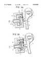
- FIG. 1shows a sectional side elevation of a preferred embodiment of the invention
- FIG. 2is an enlarged fragmentary view, showing an alternative method of supporting the diaphragm and seal
- FIG. 3Ais an enlarged sectional view of the demand valve in its closed position
- FIG. 3Bis a view similar to FIG. 3A, showing the demand valve open to admit air to the facepiece.
- a speech transmission diaphragm assembly 1comprises a taut membrane 2 held in a rigid circular housing 3.
- This diaphragm assembly 1is rigidly fixed to a lever 4, pivoted at 5 and biased by a spring 6 such that the diaphragm is urged towards a deformable resilient seal 7, clamped at its periphery to a housing 8.
- the seal 7is so configured that it can, after making sealing contact with the diaphragm assembly 1, allow further “inward” movement of the diaphragm (towards the wearer) beyond the initial "closed” position seen in FIG. 1.
- the force of the spring 6is such as to urge the diaphragm to close the opening defined by the seal 7, and is sufficient to deform or deflect the seal 7 further, beyond this initial "closed" position in the absence of a pressure difference across the diaphragm.
- a lever 9is pivoted at 10 and is biased by a light spring 11 so as to close of a small pilot jet 12.
- the relative sizes of the pilot jet 12 and metering orifice 15are such that the pilot jet 12 can exhaust the pilot chamber 13 faster than the metering orifice 15 can replenish it.
- the supply of air to the facepieceis controlled by a two-stage main valve composed of the resilient disc 16, whose opening and closing is in turn controlled by the opening and closing of a pilot arrangement, composed of the pilot chamber 13 and jet 12.
- the pilot arrangementis in turn controlled by the movement of the lever 9, which is moved by the diaphragm 1 when diaphragm 1 moves inwards in response to a reduction in pressure within the facepiece.
- the biasing spring 6is sufficiently strong to move the diaphragm, in the absence of any pressure difference across the diaphragm, from a first position in which initial contact is made with seal 7 but with seal 7 unmoved, into a third position in which seal is moved toward the wearer and the diaphragm 1 contacts the screw 9a of lever 9. The diaphragm 1 and seal 7 remain in sealing contact throughout this movement.
- a cover 21which is shown in dotted lines, protects the assembly from damage and from radiant heat, and has suitably positioned openings (not shown) to allow for the unhindered passage of the exhaled air to atmosphere. These openings also provide a path for sounds transmitted through the diaphragm 1, allowing the clear transmission of speech.
- a lifting and latching meansis provided to move the diaphragm 1 away from the resilient seal 7, and to hold it in this open position.
- a lifting arrangementis seen at 30, where the diaphragm 1 is provided with a finger tab 30 projecting downwardly from its lower end.
- the wearermay move the diaphragm away from seal 7 to allow free ingress and egress of air into the facepiece. It is emphasised that the lever 9 is unmoved by lifting the diaphragm in this way, and thus the demand valve remains closed, conserving the air supply.
- latching means 30a and 30bare provided to retain the diaphragm in its lifted position.
- detent 30aengages with pivoting latch 30b when the diaphragm is lifted by the wearer.
- Leftwards (as seen in the Figure) pressure at the lower part 30c of pivoting latch 30bcauses the latch 30b rotate clockwise and to disengage from the detent 30b, and spring 7 then returns the diaphragm 1 to its initial position in contact with seal 6, to continue the normal operating sequence.
- lifting the diaphragm 1opens a port of substantial area, directly in front of the wearer's nose and mouth.
- the latchmay be arranged in other configurations than that shown, provided the latch can operate to hold the diaphragm 1 in the open position. While the latch may be engaged and released, or "tripped", by a single action, such as by pressing a projecting button, release arrangements requiring more determined manipulation are foreseen.
- the latching meansis preferably designed to that a double action is required by the wearer to engage the latch, such as by simultaneously depressing two buttons on opposite sides of the valve assembly.
- a manually operated bypass, or override, valve(not shown) may be provided, whereby a controlled flow of air may be admitted to the facepiece at will.
- a stop valemay be provided between the pressurised air supply tank and the facepiece, since it will be appreciated that if the wearer removes the facepiece without latching the diaphragm 1 open, the diaphragm 1 will be moved by the spring 6 to open the pilot valve 12 and allow a free flow of air.
- the diaphragm 1is mounted on a resiliently biassed telescopic support comprising a bearing post 40 attached to the housing of the facepiece and a sleeve 41 attached to the outer face of the diaphragm assembly.
- a spring 42surrounds the post 40 and urges the sleeve 41 and diaphragm 1 and the seal 7 towards the wearer.
- Other mounting arrangementsare foreseen for the diaphragm, in addition to the pivotal movement shown in FIG. 1 and the rectilinear movement illustrated in FIG. 2.
- the seal 7is permanently attached to the periphery of the diaphragm 1, and has a sealing lip which contacts the body 8 of the facepiece.
- the flexible nature of the seal 7allows the diaphragm to move towards the wearer after making initial sealing contact with the facepiece, so that lever 9 may be operated to open the supply valve 16 in a manner similar to that described with reference to the embodiment shown in FIG. 1.
- the diaphragm 1is formed with a threaded embossment 1a, and an adjusting screw S extends through the embossment 1a to contact the end of a lever 9 which operates the demand valve (not shown) in a manner similar to that described in relation to FIG. 1.
- FIGS. 3A and 3Bshown in greater detail the demand valve 3.
- lever 9is urged by spring 11 (FIG. 1) to close the pilot jet 12.
- Pilot chamber 13is pressurised by air entering from the metering orifice 15, and resilient sealing disc 16 is urged by this pressure to close the exit ports 18 in the flange 17.
- Outlet 20is closed by a resilient flap 19.
- pilot jet 12When lever 9 is moved by diaphragm 1, pilot jet 12 is opened and air in the pilot chamber 13 escapes through jet 12 faster than it enters via metering orifice 15, thus depressurising the pilot chamber 13. High pressure in the supply tube 14 then deforms the disc 16, and air can pass from supply tube 14 to outlet ports 18 and thence to outlet 20, where the pressure raises resilient flap 19 and allows air to exit to the interior of the facepiece.
- the diaphragmcan be arranged so as to open the demand valve when the diaphragm 1 and seal 7 have moved inwardly from their position of initial sealing contact, and can close the demand valve as the diaphragm 1 and seal 7 move outwardly together before the diaphragm loses contact with the seal 7.
- the facepiecemay be a simple assembly of a clear plastics visor 22, attached around its periphery to a resilient seal 23 and secure to the wearer's face by means of an adjustable head harness (also not shown).
- An opening in the visor 22accommodates the integrated valve assembly previously described, which may be secured in the opening by means of screws or clips.
- the facepieceis provided with an inner half-mask 24.
- Air entering the facepiece from the valve outlet 20is directed into the upper area of the visor and passes through non-return flaps 25 into the half-mask 24, to be inhaled by the wearer. Exhaled air passes directly to atmosphere around the diaphragm 1, which is situated in front of the wearer's mouth for optimum speech transmission. This circuitous passage of the air through the facepiece prevents misting of the visor, ventilates the upper area of the wearer's face and minimises the amount of carbon dioxide inhaled by the wearer.
- the facepiececovers the entire face of the wearer.
- the combined speech transmission diaphragm, exhalation valve and demand valve control arrangement described abovemay however also be embodied in a facepiece which covers only the wearer's nose and mouth. In such cases it is foreseen that separate eye protection may be provided. This arrangement may be advantageous for example in breathing apparatus intended for aircrew.
- the combined exhaust valve and demand valvemay form part of a hood or helmet which extends to cover the entire head of a wearer.
- a hood formed from flexible materialis foreseen, sealed round the wearer's neck, and inflated by the gas supply from a demand valve actuated by a diaphragm arrangement as previously described.
- the demand valveis incorporated in a helmet, the helmet may be fully pressurised, or may have a sealing membrane engaging the wearers' head to enclose the nose and mouth and optionally the eyes. The volume within the sealing membrane will be supplied with pressurised air by the demand valve.
- the demand valvemay be incorporated into a hood or helmet forming part of a protective garment for the upper body, or of a complete body suit.
- the demand valvemay supply pressurised air at a predetermined temperature to the wearer for respiration, and the same or a further demand valve assembly may supply air to the interior of the garment or suit to cool the wearer.
- the supply of breathable gasmay be from self-contained cylinders carried by the wearer, or may be from a supply reservoir remote from the wearer and connected to the demand valve via a hose.
- the components of the demand valvemay be moulded from plastics materials, to reduce weight and cost.
Landscapes
- Health & Medical Sciences (AREA)
- Pulmonology (AREA)
- General Health & Medical Sciences (AREA)
- Business, Economics & Management (AREA)
- Emergency Management (AREA)
- Respiratory Apparatuses And Protective Means (AREA)
Abstract
Description
Claims (38)
Applications Claiming Priority (2)
| Application Number | Priority Date | Filing Date | Title |
|---|---|---|---|
| GBGB9619459.2AGB9619459D0 (en) | 1996-09-18 | 1996-09-18 | Breathing apparatus |
| GB0619459 | 1996-09-18 |
Publications (1)
| Publication Number | Publication Date |
|---|---|
| US6016802Atrue US6016802A (en) | 2000-01-25 |
Family
ID=10800101
Family Applications (1)
| Application Number | Title | Priority Date | Filing Date |
|---|---|---|---|
| US08/932,039Expired - LifetimeUS6016802A (en) | 1996-09-18 | 1997-09-17 | Breathing apparatus and facepiece therefor |
Country Status (4)
| Country | Link |
|---|---|
| US (1) | US6016802A (en) |
| EP (1) | EP0838237B1 (en) |
| DE (1) | DE69719280D1 (en) |
| GB (1) | GB9619459D0 (en) |
Cited By (40)
| Publication number | Priority date | Publication date | Assignee | Title |
|---|---|---|---|---|
| US6206003B1 (en)* | 1998-12-11 | 2001-03-27 | John M. Burch | Mask with integral valve |
| US6343603B1 (en)* | 1998-10-09 | 2002-02-05 | Fisher & Paykel Limited | Connector |
| US6401259B1 (en) | 2000-02-02 | 2002-06-11 | Gentex Corporation | Custom fitting assembly for helmet with protective hood |
| US20030034071A1 (en)* | 2001-08-15 | 2003-02-20 | Jackson Peter J. | Demand valve for breathing apparatus |
| US20030047183A1 (en)* | 2001-05-11 | 2003-03-13 | Kiefer Eileen A. | Respirator facepieces |
| US20030234016A1 (en)* | 2002-06-24 | 2003-12-25 | Swann Linsey J. | Personal emergency breathing system |
| US6736137B1 (en) | 2003-02-28 | 2004-05-18 | Tmr-A, Llc | Protective hooded respirator with oral-nasal cup breathing interface |
| US20040194829A1 (en)* | 2002-09-19 | 2004-10-07 | Zaiser Lenoir E. | Differential pressure valve employing near-balanced pressure |
| US20040244797A1 (en)* | 2003-06-06 | 2004-12-09 | Jackson Peter J. | Demand valves for breathing apparatus |
| US20060054168A1 (en)* | 2004-09-10 | 2006-03-16 | Mesure Technology Co., Ltd. | Face mask |
| US20060060193A1 (en)* | 2002-09-27 | 2006-03-23 | Richardson Grant S | Respirator |
| US7100628B1 (en)* | 2003-11-18 | 2006-09-05 | Creare Inc. | Electromechanically-assisted regulator control assembly |
| US20060225739A1 (en)* | 2005-04-12 | 2006-10-12 | Interspiro Ab | Breathing mask |
| US20100108067A1 (en)* | 2007-03-23 | 2010-05-06 | Walker Garry J | Respirator flow control apparatus and method |
| US20110209712A1 (en)* | 2010-02-26 | 2011-09-01 | Dräger Safety AG & Co. KGaA | Gas mask |
| US20130095738A1 (en)* | 2011-10-12 | 2013-04-18 | Ford Global Technologies, Llc | Powered diaphragm air extractor and control system |
| US20140014110A1 (en)* | 2012-07-16 | 2014-01-16 | Phillip M. Adams | Remotely controlled positive airway-pressure apparatus and method |
| US20150000660A1 (en)* | 2013-06-28 | 2015-01-01 | American Air Liquide, Inc. | Nasal cannula assembly with flow control passage communicating with a deformable reservoir |
| US20150000659A1 (en)* | 2013-06-28 | 2015-01-01 | American Air Liquide, Inc. | Method of treating a patient having pulmonary hypertension by long term no therapy |
| US20150000658A1 (en)* | 2013-06-28 | 2015-01-01 | American Air Liquide, Inc. | Breathing assistance assemblies suitable for long term no therapy |
| US20150000654A1 (en)* | 2013-06-28 | 2015-01-01 | American Air Liquide, Inc. | Breathing assistance apparatus for delivery of nitric oxide to a patient by means of a nasal cannula assembly with flow control passage |
| US20150000673A1 (en)* | 2013-06-28 | 2015-01-01 | American Air Liquide, Inc. | Nasal cannula assembly with inhalation valves communicating with a deformable reservoir |
| US20150000661A1 (en)* | 2013-06-28 | 2015-01-01 | American Air Liquide, Inc. | Method of delivering medical gases via a nasal cannula assembly with flow control passage communicating with a deformable reservoir |
| US20150034079A1 (en)* | 2011-06-22 | 2015-02-05 | Breathe Technologies, Inc. | Ventilation Mask with Integrated Piloted Exhalation Valve |
| US20160001106A1 (en)* | 2013-03-01 | 2016-01-07 | Draeger Safety Uk Limited | Lung demand valve |
| US9364632B2 (en) | 2010-08-19 | 2016-06-14 | Koninklijke Philips N.V. | Manually actuated talk valve for a respiratory device |
| US9517367B2 (en) | 2013-02-01 | 2016-12-13 | 3M Innovative Properties Company | Respiratory mask having a clean air inlet chamber |
| CN106617315A (en)* | 2016-11-11 | 2017-05-10 | 周成龙 | Electronic cigarette |
| US9868001B2 (en)* | 2007-10-05 | 2018-01-16 | 3M Innovative Properties Company | Respirator flow control apparatus and method |
| US9950202B2 (en) | 2013-02-01 | 2018-04-24 | 3M Innovative Properties Company | Respirator negative pressure fit check devices and methods |
| USD816209S1 (en) | 2016-03-28 | 2018-04-24 | 3M Innovative Properties Company | Respirator inlet port connection seal |
| USD827810S1 (en) | 2016-03-28 | 2018-09-04 | 3M Innovative Properties Company | Hardhat suspension adapter for half facepiece respirators |
| USD842982S1 (en) | 2016-03-28 | 2019-03-12 | 3M Innovative Properties Company | Hardhat suspension adapter for half facepiece respirators |
| US20190366133A1 (en)* | 2018-06-01 | 2019-12-05 | Avon Polymer Products Limited | Speech diaphragm module for a respirator mask |
| US11020619B2 (en) | 2016-03-28 | 2021-06-01 | 3M Innovative Properties Company | Multiple chamber respirator sealing devices and methods |
| US11052268B2 (en) | 2013-02-01 | 2021-07-06 | 3M Innovative Properties Company | Respirator negative pressure fit check devices and methods |
| US11219787B2 (en) | 2016-03-28 | 2022-01-11 | 3M Innovative Properties Company | Respirator fit check sealing devices and methods |
| US11992078B2 (en) | 2016-03-28 | 2024-05-28 | 3M Innovative Properties Company | Headwear suspension attachment element |
| US12128740B2 (en) | 2021-12-10 | 2024-10-29 | Markdom International Inc. | Vehicle accessory apparatus with incomplete assembly indicator |
| US12427835B2 (en) | 2021-10-01 | 2025-09-30 | Markdom International Inc. | Injection molded vehicle compartment pressure relief valve |
Families Citing this family (3)
| Publication number | Priority date | Publication date | Assignee | Title |
|---|---|---|---|---|
| PT1582231E (en)* | 2004-04-02 | 2012-09-27 | Intersurgical Ag | Improvements relating to respiratory masks |
| GB2490507C (en)* | 2011-05-03 | 2020-08-12 | Intersurgical Ag | Respiratory mask |
| GB2521644B (en) | 2013-12-24 | 2020-03-11 | Intersurgical Ag | Improvements relating to respiratory masks |
Citations (10)
| Publication number | Priority date | Publication date | Assignee | Title |
|---|---|---|---|---|
| US3109425A (en)* | 1960-03-04 | 1963-11-05 | Electric Storage Battery Co | Respirator speaking diaphragm and exhalation valve unit |
| US4572176A (en)* | 1982-12-10 | 1986-02-25 | Dragerwerk Aktiengesellschaft | Control for a protective mask which operates with excess internal pressure |
| US4629159A (en)* | 1985-01-08 | 1986-12-16 | Astra Meditec Ab | Valve-provided connecting device |
| US4762145A (en)* | 1987-05-13 | 1988-08-09 | G.S.D. Sports Equipment S.R.L. | Underwater pressure relief valve |
| US4834085A (en)* | 1987-12-10 | 1989-05-30 | Webster Ii John W | Person-to-person resuscitation device |
| US5042473A (en)* | 1990-02-15 | 1991-08-27 | Pro-Tech Respirators, Inc. | Demand valve for a respirator |
| US5499624A (en)* | 1992-11-05 | 1996-03-19 | Dragerwerk Ag | Breathing mask with face-contact actuated overpressure generating switch |
| US5572990A (en)* | 1994-06-08 | 1996-11-12 | Berlin; Florence | Respiratory mask and microphone mount for use therein |
| US5584288A (en)* | 1994-02-03 | 1996-12-17 | Baldwin; Gene R. | Multi-stage mouth-to-mouth resuscitator valve |
| US5749359A (en)* | 1992-05-11 | 1998-05-12 | Hansen; Iver | Portable air conditioner |
Family Cites Families (4)
| Publication number | Priority date | Publication date | Assignee | Title |
|---|---|---|---|---|
| DE2908528C2 (en)* | 1979-03-05 | 1984-04-05 | Drägerwerk AG, 2400 Lübeck | Lung-controlled breathing apparatus with positive pressure inside the mask |
| GB9301959D0 (en)* | 1993-02-01 | 1993-03-17 | Sabre Safety Ltd | A valve for use in breathing apparatus |
| SE502129C2 (en)* | 1993-11-05 | 1995-08-28 | Poseidon Ind Ab | Valve device and respirator including such valve device |
| DE4418788A1 (en)* | 1994-05-24 | 1995-11-30 | Interspiro Gmbh | Breathing connection with regulator |
- 1996
- 1996-09-18GBGBGB9619459.2Apatent/GB9619459D0/enactivePending
- 1997
- 1997-09-17EPEP97307228Apatent/EP0838237B1/ennot_activeExpired - Lifetime
- 1997-09-17USUS08/932,039patent/US6016802A/ennot_activeExpired - Lifetime
- 1997-09-17DEDE69719280Tpatent/DE69719280D1/ennot_activeExpired - Lifetime
Patent Citations (10)
| Publication number | Priority date | Publication date | Assignee | Title |
|---|---|---|---|---|
| US3109425A (en)* | 1960-03-04 | 1963-11-05 | Electric Storage Battery Co | Respirator speaking diaphragm and exhalation valve unit |
| US4572176A (en)* | 1982-12-10 | 1986-02-25 | Dragerwerk Aktiengesellschaft | Control for a protective mask which operates with excess internal pressure |
| US4629159A (en)* | 1985-01-08 | 1986-12-16 | Astra Meditec Ab | Valve-provided connecting device |
| US4762145A (en)* | 1987-05-13 | 1988-08-09 | G.S.D. Sports Equipment S.R.L. | Underwater pressure relief valve |
| US4834085A (en)* | 1987-12-10 | 1989-05-30 | Webster Ii John W | Person-to-person resuscitation device |
| US5042473A (en)* | 1990-02-15 | 1991-08-27 | Pro-Tech Respirators, Inc. | Demand valve for a respirator |
| US5749359A (en)* | 1992-05-11 | 1998-05-12 | Hansen; Iver | Portable air conditioner |
| US5499624A (en)* | 1992-11-05 | 1996-03-19 | Dragerwerk Ag | Breathing mask with face-contact actuated overpressure generating switch |
| US5584288A (en)* | 1994-02-03 | 1996-12-17 | Baldwin; Gene R. | Multi-stage mouth-to-mouth resuscitator valve |
| US5572990A (en)* | 1994-06-08 | 1996-11-12 | Berlin; Florence | Respiratory mask and microphone mount for use therein |
Cited By (62)
| Publication number | Priority date | Publication date | Assignee | Title |
|---|---|---|---|---|
| US6343603B1 (en)* | 1998-10-09 | 2002-02-05 | Fisher & Paykel Limited | Connector |
| US6206003B1 (en)* | 1998-12-11 | 2001-03-27 | John M. Burch | Mask with integral valve |
| US6401259B1 (en) | 2000-02-02 | 2002-06-11 | Gentex Corporation | Custom fitting assembly for helmet with protective hood |
| US7261104B2 (en)* | 2001-05-11 | 2007-08-28 | Mine Safety Appliances Company | Respirator facepieces |
| US20030047183A1 (en)* | 2001-05-11 | 2003-03-13 | Kiefer Eileen A. | Respirator facepieces |
| US6772785B2 (en)* | 2001-08-15 | 2004-08-10 | International Safety Instruments, Inc. | Demand valve for breathing apparatus |
| US20030034071A1 (en)* | 2001-08-15 | 2003-02-20 | Jackson Peter J. | Demand valve for breathing apparatus |
| US20030234016A1 (en)* | 2002-06-24 | 2003-12-25 | Swann Linsey J. | Personal emergency breathing system |
| US6758212B2 (en)* | 2002-06-24 | 2004-07-06 | Brookdale International Systems, Inc. | Personal emergency breathing system |
| US20040194829A1 (en)* | 2002-09-19 | 2004-10-07 | Zaiser Lenoir E. | Differential pressure valve employing near-balanced pressure |
| US20060060193A1 (en)* | 2002-09-27 | 2006-03-23 | Richardson Grant S | Respirator |
| US6736137B1 (en) | 2003-02-28 | 2004-05-18 | Tmr-A, Llc | Protective hooded respirator with oral-nasal cup breathing interface |
| US7111625B2 (en)* | 2003-06-06 | 2006-09-26 | International Safety Instruments, Inc. | Demand valves for breathing apparatus |
| US20040244797A1 (en)* | 2003-06-06 | 2004-12-09 | Jackson Peter J. | Demand valves for breathing apparatus |
| US7100628B1 (en)* | 2003-11-18 | 2006-09-05 | Creare Inc. | Electromechanically-assisted regulator control assembly |
| US20060054168A1 (en)* | 2004-09-10 | 2006-03-16 | Mesure Technology Co., Ltd. | Face mask |
| US7100611B2 (en)* | 2004-09-10 | 2006-09-05 | Mesure Technology Co., Ltd. | Face mask |
| US20060225739A1 (en)* | 2005-04-12 | 2006-10-12 | Interspiro Ab | Breathing mask |
| US7814909B2 (en)* | 2005-04-12 | 2010-10-19 | Interspiro Ab | Breathing mask |
| US20100108067A1 (en)* | 2007-03-23 | 2010-05-06 | Walker Garry J | Respirator flow control apparatus and method |
| US10137320B2 (en) | 2007-03-23 | 2018-11-27 | 3M Innovative Properties Company | Respirator flow control apparatus and method |
| US11130008B2 (en) | 2007-03-23 | 2021-09-28 | 3M Innovative Properties Company | Respirator flow control apparatus and method |
| US12329994B2 (en) | 2007-03-23 | 2025-06-17 | 3M Innovative Properties Company | Respirator flow control apparatus and method |
| US9868001B2 (en)* | 2007-10-05 | 2018-01-16 | 3M Innovative Properties Company | Respirator flow control apparatus and method |
| US8631794B2 (en)* | 2010-02-26 | 2014-01-21 | Dräger Safety AG & Co. KGaA | Gas mask |
| US20110209712A1 (en)* | 2010-02-26 | 2011-09-01 | Dräger Safety AG & Co. KGaA | Gas mask |
| US9364632B2 (en) | 2010-08-19 | 2016-06-14 | Koninklijke Philips N.V. | Manually actuated talk valve for a respiratory device |
| US20150034079A1 (en)* | 2011-06-22 | 2015-02-05 | Breathe Technologies, Inc. | Ventilation Mask with Integrated Piloted Exhalation Valve |
| US9415183B2 (en)* | 2011-06-22 | 2016-08-16 | Breathe Technologies, Inc. | Ventilation mask with integrated piloted exhalation valve |
| US20130095738A1 (en)* | 2011-10-12 | 2013-04-18 | Ford Global Technologies, Llc | Powered diaphragm air extractor and control system |
| US9410717B2 (en)* | 2011-10-12 | 2016-08-09 | Ford Global Technologies, Llc | Powered diaphragm air extractor and control system |
| US20140014110A1 (en)* | 2012-07-16 | 2014-01-16 | Phillip M. Adams | Remotely controlled positive airway-pressure apparatus and method |
| US9950202B2 (en) | 2013-02-01 | 2018-04-24 | 3M Innovative Properties Company | Respirator negative pressure fit check devices and methods |
| US9517367B2 (en) | 2013-02-01 | 2016-12-13 | 3M Innovative Properties Company | Respiratory mask having a clean air inlet chamber |
| US11052268B2 (en) | 2013-02-01 | 2021-07-06 | 3M Innovative Properties Company | Respirator negative pressure fit check devices and methods |
| US12128259B2 (en) | 2013-02-01 | 2024-10-29 | 3M Innovative Properties Company | Respirator negative pressure fit check devices and methods |
| US20160001106A1 (en)* | 2013-03-01 | 2016-01-07 | Draeger Safety Uk Limited | Lung demand valve |
| US10173083B2 (en)* | 2013-03-01 | 2019-01-08 | Draeger Safety Uk Limited | Lung demand valve |
| US9486600B2 (en)* | 2013-06-28 | 2016-11-08 | L'Air Liquide, Société Anonyme pour l'Etude et l'Exploitation des Procédés Georges Claude | Nasal cannula assembly with inhalation valves communicating with a deformable reservoir |
| US9522248B2 (en)* | 2013-06-28 | 2016-12-20 | L'Air Liquide, Société Anonyme pour l'Etude et l'Exploitation des Procédés Georges Claude | Breathing assistance apparatus for delivery of nitric oxide to a patient by means of a nasal cannula assembly with flow control passage |
| US9522247B2 (en)* | 2013-06-28 | 2016-12-20 | L'Air Liquide, Société Anonyme pour l'Etude et l'Exploitation des Procédés Georges Claude | Method of treating a patient having pulmonary hypertension by long term NO therapy |
| US9566407B2 (en)* | 2013-06-28 | 2017-02-14 | L'Air Liquide, Société Anonyme pour l'Etude et l'Exploitation des Procédés Georges Claude | Nasal cannula assembly with flow control passage communicating with a deformable reservoir |
| US20150000660A1 (en)* | 2013-06-28 | 2015-01-01 | American Air Liquide, Inc. | Nasal cannula assembly with flow control passage communicating with a deformable reservoir |
| US20150000654A1 (en)* | 2013-06-28 | 2015-01-01 | American Air Liquide, Inc. | Breathing assistance apparatus for delivery of nitric oxide to a patient by means of a nasal cannula assembly with flow control passage |
| US20150000661A1 (en)* | 2013-06-28 | 2015-01-01 | American Air Liquide, Inc. | Method of delivering medical gases via a nasal cannula assembly with flow control passage communicating with a deformable reservoir |
| US20150000659A1 (en)* | 2013-06-28 | 2015-01-01 | American Air Liquide, Inc. | Method of treating a patient having pulmonary hypertension by long term no therapy |
| US20150000658A1 (en)* | 2013-06-28 | 2015-01-01 | American Air Liquide, Inc. | Breathing assistance assemblies suitable for long term no therapy |
| US20150000673A1 (en)* | 2013-06-28 | 2015-01-01 | American Air Liquide, Inc. | Nasal cannula assembly with inhalation valves communicating with a deformable reservoir |
| US9517318B2 (en)* | 2013-06-28 | 2016-12-13 | L'Air Liquide, Société Anonyme pour l'Etude et l'Exploitation des Procédés Georges Claude | Method of delivering medical gases via a nasal cannula assembly with flow control passage communicating with a deformable reservoir |
| US9492626B2 (en)* | 2013-06-28 | 2016-11-15 | L'Air Liquide, Société Anonyme pour l'Etude et l'Exploitation des Procédés Georges Claude | Breathing assistance assemblies suitable for long term no therapy |
| USD842982S1 (en) | 2016-03-28 | 2019-03-12 | 3M Innovative Properties Company | Hardhat suspension adapter for half facepiece respirators |
| US11020619B2 (en) | 2016-03-28 | 2021-06-01 | 3M Innovative Properties Company | Multiple chamber respirator sealing devices and methods |
| USD827810S1 (en) | 2016-03-28 | 2018-09-04 | 3M Innovative Properties Company | Hardhat suspension adapter for half facepiece respirators |
| US11219787B2 (en) | 2016-03-28 | 2022-01-11 | 3M Innovative Properties Company | Respirator fit check sealing devices and methods |
| US11865375B2 (en) | 2016-03-28 | 2024-01-09 | 3M Innovative Properties Company | Respirator fit check sealing devices and methods |
| US11992078B2 (en) | 2016-03-28 | 2024-05-28 | 3M Innovative Properties Company | Headwear suspension attachment element |
| USD816209S1 (en) | 2016-03-28 | 2018-04-24 | 3M Innovative Properties Company | Respirator inlet port connection seal |
| CN106617315A (en)* | 2016-11-11 | 2017-05-10 | 周成龙 | Electronic cigarette |
| US20190366133A1 (en)* | 2018-06-01 | 2019-12-05 | Avon Polymer Products Limited | Speech diaphragm module for a respirator mask |
| US12042675B2 (en)* | 2018-06-01 | 2024-07-23 | Avon Polymer Products Limited | Speech diaphragm module for a respirator mask |
| US12427835B2 (en) | 2021-10-01 | 2025-09-30 | Markdom International Inc. | Injection molded vehicle compartment pressure relief valve |
| US12128740B2 (en) | 2021-12-10 | 2024-10-29 | Markdom International Inc. | Vehicle accessory apparatus with incomplete assembly indicator |
Also Published As
| Publication number | Publication date |
|---|---|
| GB9619459D0 (en) | 1996-10-30 |
| DE69719280D1 (en) | 2003-04-03 |
| EP0838237A2 (en) | 1998-04-29 |
| EP0838237A3 (en) | 1999-04-07 |
| EP0838237B1 (en) | 2003-02-26 |
Similar Documents
| Publication | Publication Date | Title |
|---|---|---|
| US6016802A (en) | Breathing apparatus and facepiece therefor | |
| US8215303B2 (en) | Breathing apparatus | |
| EP1341582B1 (en) | Breathing apparatus | |
| US6371110B1 (en) | Automatic release apparatus and methods for respirator devices | |
| US6394091B1 (en) | Breathing apparatus | |
| US5690095A (en) | Emergency escape breathing apparatus | |
| EP0363530A1 (en) | Respirator | |
| WO2003095031A1 (en) | Respirator assembly | |
| GB2575233A (en) | A breathing apparatus | |
| US4361145A (en) | Respirator mask | |
| US5492108A (en) | Ventilation system for protective garments | |
| EP0444028A1 (en) | Self-contained breathing apparatus. | |
| EP0632736B1 (en) | Breathing apparatus for respiratory protection | |
| GB2209123A (en) | Breathing apparatus | |
| US20030116156A1 (en) | Breathing apparatus | |
| AU705233B2 (en) | Face mask | |
| GB2454491A (en) | Emergency breathing apparatus | |
| WO1990002078A1 (en) | Simplified respirator | |
| EP0956100B1 (en) | Breathing equipment | |
| KR200498645Y1 (en) | Multifunctional auxiliary breathing device | |
| GB2470130A (en) | Spool valve for air supply which automatically switches when second air supply is connected | |
| HK1056333B (en) | Breathing apparatus | |
| GB2365357A (en) | Hooded breathing apparatus | |
| HU184043B (en) | Oxygen escape device particularly for using in mine areas |
Legal Events
| Date | Code | Title | Description |
|---|---|---|---|
| AS | Assignment | Owner name:INTERNATIONAL SAFETY INSTRUMENTS, INC., GEORGIA Free format text:ASSIGNMENT OF ASSIGNORS INTEREST;ASSIGNOR:JACKSON, PETER JOSEPH;REEL/FRAME:008759/0951 Effective date:19961001 | |
| FPAY | Fee payment | Year of fee payment:4 | |
| REMI | Maintenance fee reminder mailed | ||
| FEPP | Fee payment procedure | Free format text:PAYOR NUMBER ASSIGNED (ORIGINAL EVENT CODE: ASPN); ENTITY STATUS OF PATENT OWNER: LARGE ENTITY Free format text:PAYER NUMBER DE-ASSIGNED (ORIGINAL EVENT CODE: RMPN); ENTITY STATUS OF PATENT OWNER: LARGE ENTITY | |
| FEPP | Fee payment procedure | Free format text:PAT HOLDER NO LONGER CLAIMS SMALL ENTITY STATUS, ENTITY STATUS SET TO UNDISCOUNTED (ORIGINAL EVENT CODE: STOL); ENTITY STATUS OF PATENT OWNER: LARGE ENTITY | |
| REFU | Refund | Free format text:REFUND - PAYMENT OF MAINTENANCE FEE, 8TH YR, SMALL ENTITY (ORIGINAL EVENT CODE: R2552); ENTITY STATUS OF PATENT OWNER: LARGE ENTITY | |
| FPAY | Fee payment | Year of fee payment:8 | |
| SULP | Surcharge for late payment | Year of fee payment:7 | |
| FEPP | Fee payment procedure | Free format text:PAYER NUMBER DE-ASSIGNED (ORIGINAL EVENT CODE: RMPN); ENTITY STATUS OF PATENT OWNER: LARGE ENTITY | |
| REMI | Maintenance fee reminder mailed | ||
| FEPP | Fee payment procedure | Free format text:PETITION RELATED TO MAINTENANCE FEES FILED (ORIGINAL EVENT CODE: PMFP); ENTITY STATUS OF PATENT OWNER: LARGE ENTITY | |
| FEPP | Fee payment procedure | Free format text:PETITION RELATED TO MAINTENANCE FEES GRANTED (ORIGINAL EVENT CODE: PMFG); ENTITY STATUS OF PATENT OWNER: LARGE ENTITY | |
| LAPS | Lapse for failure to pay maintenance fees | ||
| REIN | Reinstatement after maintenance fee payment confirmed | ||
| FP | Lapsed due to failure to pay maintenance fee | Effective date:20120125 | |
| FPAY | Fee payment | Year of fee payment:12 | |
| SULP | Surcharge for late payment | ||
| PRDP | Patent reinstated due to the acceptance of a late maintenance fee | Effective date:20121120 | |
| STCF | Information on status: patent grant | Free format text:PATENTED CASE | |
| AS | Assignment | Owner name:AVON - INTERNATIONAL SAFETY INSTRUMENTS, INC., GEO Free format text:CHANGE OF NAME;ASSIGNOR:INTERNATIONAL SAFETY INSTRUMENTS, INC.;REEL/FRAME:034197/0059 Effective date:20071023 | |
| AS | Assignment | Owner name:AVON PROTECTION SYSTEMS, INC., MICHIGAN Free format text:CHANGE OF NAME;ASSIGNOR:AVON - INTERNATIONAL SAFETY INSTRUMENTS, INC.;REEL/FRAME:034394/0656 Effective date:20141117 |