US6016313A - System and method for broadband millimeter wave data communication - Google Patents
System and method for broadband millimeter wave data communicationDownload PDFInfo
- Publication number
- US6016313A US6016313AUS08/740,332US74033296AUS6016313AUS 6016313 AUS6016313 AUS 6016313AUS 74033296 AUS74033296 AUS 74033296AUS 6016313 AUS6016313 AUS 6016313A
- Authority
- US
- United States
- Prior art keywords
- communication
- hub
- information
- node
- antenna
- Prior art date
- Legal status (The legal status is an assumption and is not a legal conclusion. Google has not performed a legal analysis and makes no representation as to the accuracy of the status listed.)
- Expired - Lifetime
Links
Images


Classifications
- H—ELECTRICITY
- H04—ELECTRIC COMMUNICATION TECHNIQUE
- H04W—WIRELESS COMMUNICATION NETWORKS
- H04W88/00—Devices specially adapted for wireless communication networks, e.g. terminals, base stations or access point devices
- H04W88/14—Backbone network devices
- H—ELECTRICITY
- H04—ELECTRIC COMMUNICATION TECHNIQUE
- H04L—TRANSMISSION OF DIGITAL INFORMATION, e.g. TELEGRAPHIC COMMUNICATION
- H04L12/00—Data switching networks
- H04L12/28—Data switching networks characterised by path configuration, e.g. LAN [Local Area Networks] or WAN [Wide Area Networks]
- H—ELECTRICITY
- H04—ELECTRIC COMMUNICATION TECHNIQUE
- H04W—WIRELESS COMMUNICATION NETWORKS
- H04W72/00—Local resource management
- H04W72/50—Allocation or scheduling criteria for wireless resources
- H04W72/52—Allocation or scheduling criteria for wireless resources based on load
- H—ELECTRICITY
- H04—ELECTRIC COMMUNICATION TECHNIQUE
- H04J—MULTIPLEX COMMUNICATION
- H04J3/00—Time-division multiplex systems
- H04J3/02—Details
- H04J3/06—Synchronising arrangements
- H04J3/0635—Clock or time synchronisation in a network
- H04J3/0682—Clock or time synchronisation in a network by delay compensation, e.g. by compensation of propagation delay or variations thereof, by ranging
- H—ELECTRICITY
- H04—ELECTRIC COMMUNICATION TECHNIQUE
- H04L—TRANSMISSION OF DIGITAL INFORMATION, e.g. TELEGRAPHIC COMMUNICATION
- H04L1/00—Arrangements for detecting or preventing errors in the information received
- H04L1/02—Arrangements for detecting or preventing errors in the information received by diversity reception
- H04L1/06—Arrangements for detecting or preventing errors in the information received by diversity reception using space diversity
- H—ELECTRICITY
- H04—ELECTRIC COMMUNICATION TECHNIQUE
- H04W—WIRELESS COMMUNICATION NETWORKS
- H04W28/00—Network traffic management; Network resource management
- H04W28/02—Traffic management, e.g. flow control or congestion control
- H04W28/06—Optimizing the usage of the radio link, e.g. header compression, information sizing, discarding information
- H—ELECTRICITY
- H04—ELECTRIC COMMUNICATION TECHNIQUE
- H04W—WIRELESS COMMUNICATION NETWORKS
- H04W40/00—Communication routing or communication path finding
- H04W40/02—Communication route or path selection, e.g. power-based or shortest path routing
- H—ELECTRICITY
- H04—ELECTRIC COMMUNICATION TECHNIQUE
- H04W—WIRELESS COMMUNICATION NETWORKS
- H04W72/00—Local resource management
- H04W72/50—Allocation or scheduling criteria for wireless resources
- H04W72/56—Allocation or scheduling criteria for wireless resources based on priority criteria
- H—ELECTRICITY
- H04—ELECTRIC COMMUNICATION TECHNIQUE
- H04W—WIRELESS COMMUNICATION NETWORKS
- H04W88/00—Devices specially adapted for wireless communication networks, e.g. terminals, base stations or access point devices
- H04W88/02—Terminal devices
- Y—GENERAL TAGGING OF NEW TECHNOLOGICAL DEVELOPMENTS; GENERAL TAGGING OF CROSS-SECTIONAL TECHNOLOGIES SPANNING OVER SEVERAL SECTIONS OF THE IPC; TECHNICAL SUBJECTS COVERED BY FORMER USPC CROSS-REFERENCE ART COLLECTIONS [XRACs] AND DIGESTS
- Y02—TECHNOLOGIES OR APPLICATIONS FOR MITIGATION OR ADAPTATION AGAINST CLIMATE CHANGE
- Y02D—CLIMATE CHANGE MITIGATION TECHNOLOGIES IN INFORMATION AND COMMUNICATION TECHNOLOGIES [ICT], I.E. INFORMATION AND COMMUNICATION TECHNOLOGIES AIMING AT THE REDUCTION OF THEIR OWN ENERGY USE
- Y02D30/00—Reducing energy consumption in communication networks
- Y02D30/70—Reducing energy consumption in communication networks in wireless communication networks
Definitions
- This inventionrelates to broadband radio frequency communication systems and methods and more particularly to a system and method which provides for broadband information communication between processor-based systems through a centralized communication array.
- PSTNpublic switch telephone network
- multiplexing signalsover a existing physical link to bridge the gap and provide information communication between the systems.
- PSTNpublic switch telephone network
- Such solutionsare typically inexpensive to implement, they include numerous undesirable traits.
- these existing linksare typically not designed for high speed data communication, they lack the bandwidth through which to communicate large amounts of data rapidly.
- in-building LAN speedsincrease to 100 Mbps
- the local PSTN voice grade circuitseven more markedly represent a choke point for broadband metropolitan area access and therefore are becoming a less and less desirable alternative.
- such connectionslack the fault tolerance or reliability found in systems designed for reliable transmission of important processor-based system information.
- a fibre optic ringprovides economy if utilized by a plurality of systems, it must be physically coupled to such systems. As the cost of purchasing, placing, and maintaining such a ring is great, even the economy of multi-system utilization generally does not overcome the prohibitive cost of implementation .
- a communication array, or hubis centrally located to provide a air link between physically separated processor-based systems, or other sources of communication such as voice communication, utilizing a communication device, or node, of the present invention.
- this central arraymay be physically coupled to an information communication backbone providing communication between air linked systems and physically linked systems.
- multiple ones of such systemmay be utilized to bridge large physical separation of systems by the intercommunication of multiple central arrays.
- pervasive surface coveragemay be provided by arranging a plurality of such communication arrays to provide a cellular like overlay pattern.
- the central communication arraycomprises a plurality of individual antenna elements in time division multiplex (TDM) communication with a processor-based system.
- TDMtime division multiplex
- This systemprocesses signals received at each antenna element in order to route them to their desired destination.
- a advantage of using a plurality of individual antenna elements at the central communication arrayis that only antenna elements having a radiation pattern overlaying a remote site requiring communication service (subscriber) need be implemented at any particular time. Thereafter, as more subscribers require service by a particular hub, additional antenna elements may be installed.
- This modular expansion of the service capabilities of a hubresults in reduced initial installation costs where only a few subscribers initially require service, while maintaining the flexibility for implementation of omni directional and/or cellular overlay communication coverage not possible with point-to-point systems.
- the communication spectrum utilized by the communication systemis frequency division multiplexed (FDM) to provide multiple channels for simultaneous information communication to a plurality of subscribers.
- FDM channelsmay also be used to communicate control information through a predetermined band to network elements simultaneously with the transmission of other data.
- a carrier frequency in the millimeter wavelength spectrumsuch as 10 to 60 GHz, is used by the present invention.
- Such carrier frequenciesare desirable in order to provide a communication bandwidth sufficient for the transmission of at least 30 Mbps through each defined FDM channel of approximately 10 MHz.
- the FDM channelsmay provide full duplex by defining a transmit (Tx) and receive (Rx) channel pair as a single frequency division duplex (FDD) channel to serve a subscriber.
- Txtransmit
- Rxreceive
- FDDfrequency division duplex
- time division multiplexingmay be utilized to provide multiple, seemingly simultaneous, communications on a single FDM channel.
- ones of the FDM channelsare broke down into a predetermined number of discrete time slices (burst periods) which form a frame.
- Each burst periodmay be utilized by a different subscriber so as to result in information communication contained in a single frame, having a number of TDM bursts, being directed to/from a number of subscribers over a single FDM channel.
- full duplexingmay be synthesized on a single FDM channel by time division duplexing (TDD) through the use of burst periods like those used in TDM.
- TDDtime division duplexing
- Tx and Rx framesare defined to provide communication in a particular direction at a predefined time.
- a single frequency division channelmay be time division multiplexed to provide communication to a number of subscribers while simultaneously being time division duplexed to synthesize full duplexed communication with these subscribers.
- the communication systemmay utilize a initialization algorithm, perhaps including a token passing arrangement for shared data users, to poll subscriber's systems and determine communication attributes of each such system at each antenna element of the central array.
- This informationmay be utilized to determine the optimum assignment of resources, including antenna elements, TDM burst periods, FDD frequency assignments, and TDD Tx and Rx time assignments for each such system.
- This informationmay addition ally be utilized to provide secondary assignment of resources to maintain system integrity in the event of a anomalous occurrence, thereby providing system fault tolerance.
- FIG. 1illustrates the interconnection of processor-based systems of a preferred embodiment of the present invention
- FIG. 2Aillustrates a isometric view of the centralized communication array of a preferred embodiment of the present invention
- FIG. 2Billustrates a horizontal plane cross section view of the centralized communication array depicted in FIG. 2A;
- FIG. 2Cillustrates a vertical plane cross section view of the centralized communication array depicted in FIG. 2A;
- FIG. 3Aillustrates a embodiment of the composition of a signal communicated by the present invention during a time division multiple access burst period
- FIG. 3Billustrates a embodiment of the composition of a signal communicated by the present invention during a time division duplex burst period
- FIG. 4illustrates a embodiment of a node of the present invention
- FIG. 5illustrates a embodiment of the initialization algorithm utilized inconfiguring communication between the centralized communication array and nodes of the present invention
- FIG. 6illustrates the interconnection of processor-based systems through a network of hubs of the present invention.
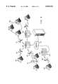
- FIGS. 7-8illustrates of a preferred embodiment of the various components of a hub of the present invention.
- the present inventionprovides high speed data communication via a broadband air interface allowing data access between subscriber's remotely located systems.
- wireless communicationmay be utilized, for example, to provide high speed bridging of a physical gap between a plurality of processor-based systems, as illustrated by system 100.
- the processor-based systemsmay include local area networks (LAN), such as LANs 110 and 120, or individual computer systems, such as PC 130.
- LANlocal area networks
- the processor-based systems utilizing the present inventionmay be general purpose computers, both standing alone and interconnected such as by a LAN.
- the systemcan connect other communication systems such as voice or video incombination with, or inplace of, communication sourced by the above mentioned processor-based systems.
- Systems bridged by the present inventionmay utilize a communication device, hereinafter referred to as a "node,” for communicating with a centralized communication device also of the present invention, hereinafter referred to as a "hub.”
- a hubis illustrated as element 101 and several nodes are illustrated as elements 150, 151, and 152 connected to LANs 110 and 120 as well as to PC 130.
- such wireless communicationmay be utilized to provide high speed communication between a processor-based system, having a node coupled thereto, and communication backbone, such as backbone 160, through hub 101.
- backbone 160may be any form of communication means, such as a broadband fibre-optic gateway or other broadband data grade connection, T1 communications lines, a cable communication system, the Internet, or the like, physically connected to hub 101.
- backbones, such as illustrated by backbone 160may be utilized to interconnect a plurality of hubs into a communications network.
- a communication network comprising a plurality of hubsis illustrated inFIG. 6.
- a nodesuch as node 150
- indirect communication with one hubsuch as hub 101
- a nodesuch as node 621
- another hubsuch as hub 620
- Such communicationmay be accomplished through the two hubs interconnection via a backbone, such as backbone 160.
- backbonesuch as backbone 160
- intercommunication between hubsmay be accomplished through information "back-hauling" via air gap communication between two hubs such as is illustrated with hubs 101 and 630.
- a communications networkmay include any number of hubs incommunication with other hubs, through such means as air gap or direct backbone interconnection, or the like.
- Information communicated from a node indirect communication with one hubmay be routed through various such interconnections to a node in direct communication with any hub of the communication network.
- the hub of the present inventionis an omni directional antenna array having a plurality of individual antenna elements.
- One such individual antenna elementis depicted as antenna element 200 in FIG. 2A.
- the antenna elementsare narrow beam directional antennas having a predetermined communication lobe. These antenna elements are arranged in an array to provide an omni directional composite radiation pattern.
- only the number of antenna elements required to communicate with a predetermined number of remote systems, rather than an omni directional configuration,may be used, if desired.
- the antenna elements comprising hub 101such as antenna element 200, provide directional reception of extremely high frequency (EHF), such as that of 38 GHz providing millimeter wave (mmWave) communication in the Q-band.
- EHFextremely high frequency
- mmWavemillimeter wave
- Such frequenciesare advantageous as they have small wave lengths which are desirable for communication by highly directional antennas.
- antennas utilized for communication of such frequenciesmay be physically small while providing large signal gain.
- the combination of such highly directional antennas with high gainprovides for improved frequency reuse and reduces the likelihood of multi-path interference. Additionally, the large gainrealized by such antennas is necessary to allow for communication over a reasonable distance from the antenna, such as, for example, three (3) miles from point to point while using reasonable power levels.
- individual antenna elementsare arranged azimuthally, as illustrated in FIG. 2B, to cover a full 360 degree radius in a horizontal plane. It shall be appreciated that arranging antenna elements in this manner can provide blanket radio communication coverage radially about hub 101 by selecting the communication lobe of each antenna element to provide coverage in areas where the neighboring antenna elements are not so providing coverage.
- the addition of antenna elements sufficient in number to provide a full 360 degree radiation patternmay be accomplished modularly as system use demands. It shall be appreciated that, even where ultimately 360 degree coverage is desired, the modular nature of the individual antenna elements provides an economic means by which to provide initially limited coverage to a developing area. For example, where only a few locations, or subscribers, within a geographic area covered by a particular hub site are desirous of communications by the present invention, a hub, including only those antenna elements necessary to service these subscribers, may be erected. Thereafter, as additional subscribers desire service within the service area of the hub, additional antenna elements may be added to the hub to provide service to their associated nodes. Ultimately the hub may be filled out with individual antenna elements to achieve communications in a full 360 degree radius about the hub.
- a hub frame adapted to accept individual antenna elements at predetermined positionsmay be initially erected. Thereafter, individual antenna elements may be coupled to this hub frame inpositions corresponding to areas requiring service or increased service density.
- a hub mast and platter, or other support structuremay be initially erected.
- individual antenna element structurescould be added to the hub support structure.
- each antenna elementincludes its own support and mounting structure to couple it to the hub support structure and any neighboring antenna element structures. It shall be appreciated that such a embodiment provides for reduced startup cost where only a few antenna elements are required to initially service the area. Furthermore, such an embodiment provides for more flexibility in positioning individual antenna elements as the antenna elements are not limited to positioning dictated by a preexisting frame structure.
- a total of 22 individual antenna elementshaving a communication lobe with approximately a 16 degree azimuthal beam width and a 2.5 degree elevational beam height, are utilized to accomplish 360 degree communication about hub 101.
- any number of individual elementscould be utilized depending on individual design constraints, such as the presence of reflected waves and their associated multipath interference. Additionally, as discussed above, only the number of antenna elements needed for communication with certain identified nodes 150 may be used if desired.
- antenna elements with a 16 degree azimuthal beam widthis advantageous inproviding a desirable reuse of channels, both at the hub and in a cellular overlay pattern providing channel reuse of the various hubs.
- an antenna element operating in the mmWave spectrum, configured as described above to have approximately a 16 degree beamhas been found to have side lobe characteristics to permit reuse of the same channel at an antenna element located on the same hub displaced approximately 90 degrees radially.
- each antenna element 200 of the preferred embodimentis comprised of horn 210 and module 220.
- horn 210is a hybrid mode lens corrected horn providing approximately 32 dB of gain.
- Module 220is a synthesized mmWave front-end module accepting and transmitting 38 GHz radio frequency energy through horn 210 converted to/from an intermediate frequency (IF), such as in the range of 400-500 MHz, for communication with a modem, such as modem 240 illustrated in FIG. 2C.
- IFintermediate frequency
- the components of the antenna elementsmay be different than that stated above.
- the horn and module attributes of the antenna elementsmay be different than that stated above where, for example, a different carrier frequency or beam pattern is desired.
- modem 240is a wideband modem capable of 42 Mbps throughput using quadrature amplitude modulation (QAM).
- QAMquadrature amplitude modulation
- the systemmay utilize a variable rate modem, such as is available commercially from various manufacturers including BroadCom Corporation , Philips, and VLSI Technology.
- a variable rate modemprovides for the transmission of variable information densities (i.e., various numbers of bits per symbol), for example from 17 to 51 Mbps (corresponding to 4 QAM, encoding two bits per symbol, up to 256 QAM, encoding 8 bits per symbol), at a fixed baud rate, such as 8.5 Mbaud.
- variable modemtypically such a modem utilizes matched data filtering that results in an occupied RF bandwidth that is 15% to 30% in excess of the theoretical Nyquist bandwidth.
- the variable modemca be useful in increasing spectral efficiency by changing the density of the information communicated to the served users depending o communication attributes such as their relative distance from the hub.
- a increased density of data in a particular time framemay be communicated to a node, geographically positioned near a hub, by the use of 256 QAM using the same occupied RF bandwidth and substantially the same transmitter power as the transmission of a signal containing a decreased density of data to a node, geographically positioned on the fringe of the hub's radiation pattern, by the use of 4 QAM.
- the transmission of increased data density to the near node without the need for significantly increased poweris achievable in part because of lessened effects of signal attenuation, and thus a higher signal to noise ratio associated with a give power level, for the near node as compared to the far node.
- the higher signal to noise ration experienced at the near nodecan typically sustain increased information density.
- Link management informationsuch as control signals adjusting the aforementioned information density, and/or error correction information may be multiplexed as control information into the data stream communicated by the modem.
- the control informationmay include multiplexed filtering and error correction information, such as forward error correction (FEC) data embedded in the data stream.
- FECforward error correction
- any number of methods of providing link management and error detection/correctionmay be provided through the use of information multiplexed through a data stream communicated by a modem of the present invention .
- the individual antenna elementsare arranged in a number of tiers. These tiers may simply be a identified group of antenna elements, or may be a physically delineated arrangement of antenna elements. Regardless of their physical interrelation ship, a tier of antenna elements includes any number of antenna elements having substantially non-overlapping radiation patterns. Illustrated in FIG. 2C is one embodiment including three vertical tiers of antenna elements. Each tier of hub 101 is preferably disposed to provide substantially the same far field radiation pattern. However, antenna elements of different tiers are preferably adapted to provide simultaneous communication on a channel, or channels, different than antenna elements having overlapping radiation patterns.
- an antenna element from a first tiermay communicate through the use of a first frequency band while an antenna element from a second tier communicates through the use of a second frequency band.
- the antenna element from the first tiermay, although utilizing a same set of channels as an antenna element of the second tier, communicate through one particular channel of the set while the antenna element of the second tier communicates through a different channel.
- the use of these different frequenciesprovides a convenient means by which additional communication capacity may be served in a defined geographic area.
- the hubis fully scalable and may include a number of tiers, different than that illustrated. Any number of tiers, including any number of antenna elements, may be utilized by the present invention. For example, a single tier of antenna elements may be used to provide omnindirectional communication from hub 101 where increased communication density is not required. Similarly, two tiers, each including only a single antenna element, may be used to provide increased capacity in a limited area defined by the radiation pattern of the antenna elements.
- tiersmay be added, as was discussed above with respect to the addition to individual antenna elements. For example, where it is determined that a hub including any combination of tiers is insufficient to provide the required communication density, antenna elements comprising any number of additional tiers may be added. Of course, where only a particular portion of the area serviced by the hub requires increased communication density, the added tiers may include only those antenna elements having a radiation pattern covering the particular portion needing increased communication density, if desired.
- the tiers of antenna elementscould be disposed to provide different radio communication coverage areas about hub 101. Such differences in radio communication coverage may be accomplished, for example, by adjusting the different tiers to have differing amounts of "down tilt" with respect to the vertical axis. Dow tilt of the tiers may be accomplished by the physical tilting of the individual antenna elements or by any number of beam steering techniques know in the art. Additionally, adjustment of the down tilt may be made periodically, such as dynamically during antenna operation, by the inclusion of a mechanical adjustment or the aforementioned beam steering techniques.
- antenna elements having different radiation pattern attributesmay be utilized to provide the defined radio communication coverage areas discussed above. For example, antenna elements utilized to provide communication in an area near a hub may provide a radiation pattern having a broader beam, and thus a lower gain, than the preferred embodiment of the antenna elements described above. Likewise, antenna elements utilized to provide communication in an area more distant from the hub may provide a radiation pattern having a narrower beam, and thus a higher gain.
- the individual tierscould be used to provide coverage patterns forming concentric circles combining to provide substantially uninterrupted coverage of a predefined area around hub 101.
- the individual antenna elementsmay be adjusted to have a down tilt or radiation pattern different than other antenna elements of the tier or hub.
- Either arrangementcould be utilized to provide substantially homogenous communication coverage where, for example, geographic elements exist which interfere with the various radiation patterns.
- this alternative embodimentmay be utilized to compensate for any number of near/far related communication anomalies.
- hub 101includes outdoor unit (ODU) controller 230 coupled to each individual antenna element 200.
- ODU controller 230is coupled to RF modem 240 and indoor unit (IDU) controller 250.
- IDU controller 250Although a separate connection from ODU controller 230 is illustrated to modem 240 and CPU 260, it shall be appreciated that communication between ODU controller 230 and IDU controller 250 may be accomplished through the path connecting modem 240 to the ODU controller and CPU 260.
- control information relevant to the operation of ODU controller 230may be generated by modem 240 rather than CPU 260 and therefore be communicated through a connection between ODU controller 230 and modem 240.
- ODU controller 230includes circuitry suitable for enabling the various antenna elements of hub 101 to communicate with RF modem 240 at the proper interval so as to transmit or receive the desired signal.
- ODU controller 230includes a time division digitally controlled switch operating in synchronization with burst periods defined by IDU controller 250.
- IDU controller 250provides a strobe pulse to the switch of ODU controller 230 to provide switching in synchronization with burst periods defined by IDU controller 250. It shall be appreciated that utilization of such a switch provides simple integration into the antenna array at a low cost. However, any switching means synchronizable to the burst periods defined by IDU controller 250 may be used if desired.
- Operation of ODU controller 230results in each individual antenna element being in communication with IDU controller 250 according to a predetermined regime of communication sequence timing, i.e., frames of burst periods. This, in turn, results in each individual antenna element being in communication with modem 240 within IDU controller 250. It shall be appreciated that such switching results in the time division multiplexing (TDM) of each antenna element to modem 240.
- TDMtime division multiplexing
- a second connection between ODU controller 230 and the various antenna elements, such as show in FIG. 8,may be provided.
- Such a connectionmay be utilized to provide synchronization, such as through the above discussed strobe pulse, to circuitry within the antenna elements to select between transmit or receive circuits at a proper frame and/or burst period.
- the antenna elementsmay be coupled to modem 240 at the proper instances to provide bi-directional communication through modem 240 resulting in time division duplexing (TDD) as described in detail hereinafter with respect to a best mode of practicing the invention.
- TDDtime division duplexing
- a connection between the antenna elements and ODU 230may be utilized for other control functions.
- a control signal through such a connectionmay be used to dynamically adjust an antenna element for a particular frequency determined to be suitable for communication with a communication device during a particular burst period of a frame.
- a control signalis provided by CPU 810 to a tuner, such as up/down-converters 892 and 893 within antenna module 220, as show in FIG. 8.
- Such a control signalmay be provided by the control processor to program phase lock loop circuitry, or synthesizer hardware, within the various antenna modules to select a particular frequency for transmission and/or reception of communicated information.
- a control signalmay be provided to adjust the amplitude of a transmitted or received signal.
- tuners 892 and/or 893may include amplification /attenuation circuitry adjustable under control of such a control signal. It shall be appreciated that both of the above described control functions result in a method by which the various antenna elements may be dynamically configured to communicate with nodes of the system.
- IDU controller 250includes a processor identified as CPU 260, electronic memory identified as RAM 270, and a interface and/or router identified as interface/router 280.
- RAM 270Stored within RAM 270 is a switching instruction algorithm to provide switching instruction or synchronization to ODU controller 230. Buffering for information communicated through modem 240 or interface/router 280 may also be provided by RAM 270.
- RAM 270may also contain additional stored information such as, for example, antenna element correlation tables, link management information, initialization instructions, modem configuration instructions, power control instructions, error correction algorithms, and other operation instructions discussed further below.
- FIG. 2CAlthough a single modem is depicted in FIG. 2C, it shall be appreciated that the hub system of the present invention is fully scalable to include any number of modems depending on the information communication capacity desired at the hub. Attention is directed toward FIG. 7 where the IDU controller of the present invention adapted for TDD communication is illustrated as including two modems.
- Modems 240 and 700 of FIG. 7are similarly configured to include burst mode controllers 720 and 721, QAM modulators 730 and 731, QAM demodulators 710 and 711, as well as channel direction control circuitry, shown as TDD switches 740 and 741.
- burst mode controller 721is synchronized with master burst mode controller 720 as well as sync channel modulator 760.
- This synchronization of burst mode controllers, illustrated as a control signal provided by master burst mode controller 720is to provide a means by which the burst periods, and thus the communication frames, of the modems as well as the TDMA switching of the individual antenna elements may be fully synchronized.
- the synchronization clockis sourced from interface/router 280 and is derived from the bit stream by master burst mode controller 720.
- master burst mode controller 720synchronization may be accomplished by means other than the use of a control signal provided by a master burst mode controller, such as the use of internal or external clock sources, if desired.
- One advantage of synchronization of the various components of the hubis restricting transmission and reception by each of the individual antenna elements to predefined time periods which allows for a greater reuse of channels as is discussed in detail with respect to the best mode for carrying out the present invention .
- sync channel modulator 760provides a means by which the timing information of the burst mode controllers may be modulated for provision to ODU controller 230. It shall be appreciated that in the preferred embodiment where CPU 260 provides control signals to the ODU for the above discussed control functions, sync channel modulator 760 may also include MUX 761 to provide a multiplexed signal to modulator 762.
- the signals of the various modems of the hubare imposed upon different carrier frequencies, such as is illustrated by IF 1 of modem 240 and IF 2 of modem 700.
- sync channel modulator 760imposes the control signal including the burst mode timing information and control functions on a suitable IF.
- These separate signalsmay the be easily combined by splitter/combiner 750 for transmission through a unitary coupling to ODU controller 230.
- the same IFcould be used as a carrier by the modems of the hub if, for example, multiple connections or a multiplexer connection were maintained between IDU controller 250 and ODU controller 230.
- IDU controller 250requires circuitry inODU controller 230 in addition to the switch enabling TDMA access to a single data stream of one modem discussed above. Attention is now directed toward FIG. 8 wherein ODU controller circuitry corresponding to the inclusion of multiple modems within IDU controller 250 is shown.
- switches 870 and 871 and signal splitter/combiners 880, 881, and 882 in combination with synchronizer 830accomplish TDMA switching of the antenna elements with respect to the individual modems as described previously with reference to the use of a single modem.
- sync channel modulator 860utilized to demodulate the burst mode control signal and various other control signals provided the ODU by the unitary connection illustrated.
- sync channel modulatorincludes MUX 861 in combination with demodulator 862 to provide CPU 810 with control information was well as providing synchronizer 830 with timing information .
- sync channel modulator 860may be omitted.
- Switches 870 and 871are adapted to provide selection of the different data streams provided by each modem, as tuned to a common intermediate frequency by tuners 840 and 841, to the antenna elements.
- module 220 of the antenna elementis adapted to accept intermediate frequencies and convert them for transmission at the desired frequency through horn 210.
- module 220is adapted to accept a single IF. Therefore, ODU controller 230 includes tuners 840 and 841 to adjust the various intermediate frequencies of the different modems, here IF 1 and IF 2 , to a common intermediate frequency IF a .
- the signals from the modemsare physically separated for switchable connection to a proper antenna element, through signal combiners 880, 881, and 882, by switches 870 and 871 under control of synchronizer 830. It shall be appreciated that, by controlling switches 870 and 871, any sequence of burst periods from any modem may be transmitted by any antenna element.
- module 220may be adapted to accept various intermediate frequencies.
- a variable tuner in module 220such as through the use of programmable phase lock loop circuitry, could be utilized to select a signal modulated by a particular modem from a composite signal by tuning to a particular intermediate frequency under control of CPU 810 and synchronizer circuitry 830.
- tuners 840 and 841as well as switches 870 and 871 and signal combiners 880, 881, and 882 may be eliminated, if desired.
- each antenna elementis adapted for bi-directional communication . Therefore, each antenna module 220 may include TDD switches 890 and 891 coupled to synchronizer 830 to provide synchronous switching the antenna element during transmit and receive frames, as is illustrated with respect to antenna element 200.
- each antenna module 220may also include a tuner to up-convert and/or down-convert the IF to the desired RF for radio communication .
- the use of tuners to both up-convert and down-convert the signalis illustrated in FIG. 8 as up converter 892 and down converter 893. It shall be appreciated, although a converter is illustrated for both the transmit and receive signal path within antenna module 220, that a single bi-directional converter may be utilized if desired. Of course, where a bi-directional converter is used, TDD switches 890 and 891 may be eliminated to result in a configuration as discussed above with respect to IF tuners 840 and 841.
- converters 892 and 893include multiple stages of converters to up-convert or down-convert the signal betwee 400-500 MHz, 3 GHz, and 38 GHz.
- an intermediate frequency closer to the radio frequencymay be utilized, thus eliminating the need for both precise filtering of the converted signal and the above described multi-stage conversion.
- itshall be appreciated that it is typically more economical to manufacture a switching matrix suitable for lower frequencies than for higher frequencies. Therefore, in the preferred embodiment, a intermediate frequency significantly lower than the radio frequency to be transmitted is utilized.
- data communicationis provided by breaking the available spectrum down into discrete channels for frequency division multiplexing (FDM).
- FDMfrequency division multiplexing
- the available spectrummay be the 1.4 GHz spectrum between 38.6 GHz to 40.0 GHz.
- This 1.4 GHz spectrummay advantageously be subdivided into 14 channels of 100 MHz each.
- other divisions of the available spectrumwhich provide a signal bandwidth sufficient to communicate the desired information may be adopted.
- a single 100 MHz channelmay be further subdivided into a pair of 50 MHz channels whereby there is defined a 50 MHz transmit (Tx) channel and a 50 MHz receive (Rx) channel.
- Txtransmit
- Rxreceive
- each 100 MHz channelmay be fully utilized as either a Tx or Rx channel, if desired.
- utilization of the full 100 MHz spectrum of a channelresults in a half duplex channel, as no spectrum remains within that channel to enable reverse transmission of information.
- full duplexingmay be synthesized on any single channel through the use of TDD to provide a Tx and Rx frame within the channel.
- Each Tx and Rx channelmay similarly be divided into 5 discrete sub-channels of 10 MHz each, resulting infrequency-division multiplexing of the 50 MHz Tx and Rx channels. Due to the aforementioned TDMA of each antenna element, each channel is divided into predefined TDMA time slots. These TDMA time slots may be further broke down into protocol time slots; a protocol time slot being a sufficient time for communicating a information packet formatted to a predefined protocol. For example, each 10 MHz sub-channel may be utilized to communicate three 10 Mbps Ethernet data packets in a 250 ⁇ sec TDMA time slot utilizing 64 QAM.
- these sub-channelsmay be utilized to provide different data throughput such as one 10 Mbps Ethernet data pack ina 250 ⁇ sec frame with quaternary phase-shift keying (QPSK) for example.
- QPSKquaternary phase-shift keying
- each Tx and Rx channelmay be utilized as a single channel spanning the full 50 MHz bandwidth, without frequency division, if desired.
- FIG. 3AA example of sub-channel 30 Mbps communication per TDMA time slot formatted as three Ethernet data packets is show in FIG. 3A.
- the 250 ⁇ sec framecontains control header 300 followed by guard time sync field 301.
- Sync field 301is followed by 10 Mbps LAN data packet 302 and forward error correction data 303, which is itself followed by guard time sync field 304.
- Sync field 304is similarly followed by 10 Mbps LAN data packet 305 and forward error correction data 306 as well as guard time sync field 307.
- Sync field 307is trailed by 10 Mbps LAN data packet 308 and forward error correction data 309 also followed by guard time sync field 310.
- this example of 30 Mbps communicationis but one embodiment of the composition of a signal withina single channel of the present invention.
- control functionsmay also be communicated between hub 101 and node 150.
- a example of such control communicationsis illustrated in FIG. 3A as control header 300.
- control functionsmay be communicated through a predetermined channel or sub-channel of the FDM spectrum. These control functions might include requests for re-transmission of a data packet, requests to adjust the amplitude of the transmitted signal, TDM timing information, instructions to adjust the modulation density, or dynamic assignment of hub resources. The use of such control functions are discussed in further detail below.
- Information communicated to IDU controller 250 via the antenna elementsmay be re-directed by hub 101 through a backbone, such as backbone 160 illustrated in FIG. 6, ultimately to other processor-based systems. It shall be understood that a plurality of such backbone communications means may be coupled to a single hub 101.
- information communicated to IDU controller 250may be re-directed by hub 101 through a preselected antenna element, when switched in communication with controller 250, ultimately to be received by another processor-based system.
- this communication pathis illustrated, for example, by network 110 communicating through hub 101 to network 120.
- hubs 101 and 630are in communication through an air link via antenna elements. These two hubs may provide information communication between any combination of processor-based systems in communication with either hub.
- IDU controller 250 of hub 101may be re-directed in a variety of ways.
- IDU controller 250correlates communication through a particular antenna element 200, or burst period associated therewith, as indicated by control of ODU controller 230, with a predefined communication path.
- communication received by IDU controller 250 at antenna element 200a illustrated in FIG. 2Cmay be routed by IDU controller 250 through antenna element 200b, as indicated by a correlation table, or the like, in RAM 270.
- Such a correlation table, or other correlation informationcould be utilized by IDU controller 250 to direct any communication received through a particular element, burst period, or channel of hub 101, including a backbone, to another particular element, burst period, or channel of hub 101.
- Such a embodimentis efficient where, for example, a processor-based system, in communication with hub 101 through antenna element 200a, is only desirous of communicating with a processor-based system, in communication with hub 101 through element 200b.
- information communicated through hub 101includes routing information .
- Such informationis preferably in the form of data packets conforming to the open systems interconnection (OSI) model.
- OSI routing informationis the transmission control protocol (TCP) standard.
- TCPtransmission control protocol
- modem 240modulates and demodulates communication between the antenna elements and IDU controller 250. Therefore, RF communication received at any antenna element may be stored within RAM 270 as digital information. Interface/router 280 may utilize predetermined pieces of information contained within the digital information, such as may be stored in RAM 270, to determine the routing of the received communication. In the preferred embodiment, routing information is provided by the network layer of a data packet conforming to the OSI model. Such information would be, for example, contained within each LAN data packet illustrated in FIG. 3.
- the digital informationmay be re-directed by hub 101 through backbone 160 or through an antenna element via modem 240. It shall be understood that, because of the utilization of TDMA, the digital information may be stored in RAM 270 until such time as ODU controller 230 couples the correct antenna element, as determined by the routing information, to IDU controller 250, and thus provides the necessary route for communication.
- node 150is comprised of two primary components, outdoor unit 410 and indoor unit 450, as depicted in FIG. 4.
- Outdoor unit 410includes antenna 420, module 430 and modem 440. Where EHF is used, antenna 420 is preferably a parabolic dish antenna providing approximately 42 dB of gain with a communication lobe of approximately 2 degrees.
- Module 430like module 220 discussed above, is a synthesized mmWave front-end module accepting and transmitting 38 GHz RF through antenna 420 converted to an IF in the range of 400-500 MHz for communication with RF modem 440.
- module 430includes the various tuner and TDD switching components illustrated in FIG. 8 with respect to module 220. However, it shall be understood that any number of component configurations are acceptable for use in module 430, as they are in module 220.
- the link illustrated between CPU 460 and module 430may provide a signal controlling the synchronized switching the synchronized switching of the TDD switches according to a TDD frame of an associated hub.
- Modem 440may be a variable rate modem, having a fixed baud rate with a variable density of bits per symbol, corresponding to the use of a variable rate modem utilized at a associated hub.
- the antenna and module attributes of node 150may be different than that stated above where, for example, a different carrier frequency or beam patter is desired.
- Indoor unit 450includes CPU 460, RAM 470 and interface 480. It shall be understood that indoor unit 450 and outdoor unit 410 are coupled such that information received by antenna 420 as RF energy is communicated to indoor unit 450.
- Interface 480provides data communication between indoor unit 450, and thus node 150, and a processor-based system such as LAN 490 illustrated in FIG. 4. Furthermore, interface 480 formats the data communication to be compatible with the processor-based system so coupled. As for example, where LAN 490 is coupled to node 150, interface 480 may both send and receive Ethernet data packets where LAN 490 utilizes Ethernet compatible communication protocol. However, where node 150 is coupled to a single computer, it may be advantageous for interface 480 to provide a synchronous receive/transmit protocol. It shall be appreciated by one of skill in the art that interface 480 may include multiple communications protocols within a single embodiment, being user selectable, or may be individual modules to be included within controller 450 as needed.
- RAM 470is coupled to both interface 480 and CPU 460. Where TDM is being used at hub 101, RAM 470 may store information received at node 150 through interface 480 while awaiting transmission to hub 101. RAM 470 may also contain additional stored information such as, for example, initialization instructions and link management information such as modem configuration instructions, power control instructions and error correction instructions discussed in detail below.
- RAM 270 of hub 101 and RAM 470 of node 150may include instructions for the operation of CPUs 260 and 460 respectively. These instructions may include, for example, a method for programming hub 101 and node 150 for communication and a method for link management including communication error correction.
- both RAM 270 and RAM 470may temporarily store information communicated via the device for re-transmission in the case a transmission error is detected.
- Transmission errormay be detected by CPUs 260 and 460 by various methods.
- One such method well know in the artis the transmission of error detection information accompanying transmitted data packets. Such a method is defined in the data link layer of the aforementioned OSI model.
- each of the three illustrated data packetsincludes associated forward error correction (FEC) information.
- FEC informationmay include a summary indication of the content of the associated data packet by such means as a checksum, a parity indication, or the like. This summary indication may be generated by the transmitting CPU, CPUs 260 or 460, or may be integral to the particular transmission protocol utilized by the processor based systems as, for example, data packets conforming to Ethernet protocol. Regardless of its source, this information may be utilized to detect errors in the transmitted data and to subsequently correct the error such as by requesting retransmission of the effected data packets.
- both RAM 270 and RAM 470store communicated information in a form readable by CPUs 260 and 460 respectively. Therefore, CPUs 260 and 460 may utilize predetermined pieces of information contained within the digital information in RAM 270 and RAM 470 respectively to detect communication errors. For example in the embodiment illustrated in FIG. 3A, the receiving CPU may generate a summary indication of the content of each LAN data packet stored within RAM and compare this to the associated FEC information. Upon determining a difference between the two summary indications, the receiving CPU may request re-transmission of the LAN data packet by the sending CPU.
- the FEC informationincludes data redundancy in the data stream using special encoders.
- decoders available at a recipient sitemay be utilized to provide error correction of portions of the data stream.
- Such error correction from encoded redundant datais capable of correcting transmitted information which includes up to a predetermined percentage of errors in the transmission.
- the FEC information so utilizedis a block code such as the Reed-Solomo FEC protocol.
- the receiving CPUmay decode information transmitted within the FEC data packet and compare this information to the content of each ATM data packet stored within RAM. Upon detecting a transmission error through such comparison, the receiving CPU may correct the ATM data packet utilizing redundant data encoded in the FEC data packet.
- the receiving CPUmay correct the ATM data packet utilizing redundant data encoded in the FEC data packet.
- transmission of the data packetis effected to the point of being beyond correction utilizing the encoded redundant data of the FEC data packet, retransmission of the data packet may be utilized, if desired.
- a predetermined sub-band of a communication channelmay be utilized for the transmission of control functions such as the above mentioned retransmission request or other control functions, such as power level adjustment and information density adjustment.
- control functionsmay be included in each TDMA burst transmission as, for example, control header 300 illustrated in FIG. 3A or control channel block 363 illustrated in FIG. 3B.
- the corresponding CPUwill detect the request for re-transmission present in the predetermined control function sub-band or control header and respond with re-transmission of the requested IAN data packet.
- the preferred embodimentalso includes a link maintenance algorithm to monitor communication parameters, such as errors in communications, associated with particular nodes 150 in RAM 270 of the hub.
- a link maintenance algorithmto monitor communication parameters, such as errors in communications, associated with particular nodes 150 in RAM 270 of the hub.
- CPU 260may transmit a instruction to the particular node to make appropriate adjustment.
- CPU 260may instruct node 150 to adjust communication transmission power to achieve an acceptable error rate or to adjust the M-ary QAM signaling level (i.e., adjust the number of bits per symbol, hereinafter referred to as the QAM rate) at which information is transmitted.
- CPU 260may also provide such control signals to the various QAM modulators associated with the hub to result in the proper modulation/demodulation of the signal communicated to the node.
- these control functions associated with link maintenancemay be communicated between CPU 260 and CPU 460 by means of a designated control function sub-band or control header.
- CPU 460Upon detecting a control instruction to adjust communications, CPU 460 provides the necessary instruction to the proper component. For example, as discussed above with respect to the hub, CPU 460 may cause module 430 to adjust transmission power or may cause modem 440 to adjust the QAM rate, depending on the attribute effected or the control information transmitted by the hub.
- a control signalmay be provided by CPU 460 to a tuner within antenna module 430.
- a control signalmay be provided by the control processor to program phase lock loop circuitry, or synthesizer hardware, within the antenna module to select a particular frequency for transmission and/or reception of communicated information .
- a control signalmay be provided to adjust the amplitude of a transmitted or received signal.
- tuners within module 430such as those illustrated in module 220 in FIG. 8, may include amplification/attenuation circuitry adjustable under control of such a control signal.
- These attributes, as well as the adjustment of the information density of communicated data,may be made by the node in response to a determination node at the hub and communicated through a control channel or may be made by a algorithm at the node. It shall be appreciated that adjustment of some attributes by the node may require a corresponding adjustment at the hub, such as with adjustment of QAM rate or channel. Therefore, the node may communicate control functions to the hub in such situations.
- RAM 470is utilized to store instructions to be utilized by CPU 460 in operating node 150. Such instructions may include channels in the available spectrum not to be utilized by node 150, windows of communication available for communication between node 150 and hub 101 due to TDM, and synchronizing information, such as frame timing and propagation delay offset, to enable TDM and/or TDD communication. Furthermore, RAM 470 may also store instructions to be utilized by CPU 460 for dynamic assignment of hub resources such as the above mentioned channels available for communication and windows of communication, or burst periods, as discussed hereinafter.
- RAM 470includes an initialization algorithm as part of the above mentioned communication instructions.
- such a initialization algorithmmay be stored in a processor-based system in communication with node 150 to achieve the same results if desired.
- the initialization algorithmoperates in conjunction with a similar algorithm stored at hub 101.
- the initialization algorithm utilized by hub 101alternatively may be stored in a processor-based system in communication with hub 101 to achieve the same results.
- the initialization algorithm at hub 101operates to cause node 150 to transmit a predetermined signal over the available spectrum to enable the mapping of communication parameters, such as signal strength, as received at each antenna element of hub 101.
- This informationmay the be utilized by the present invention to determine the individual antenna elements best suited for communication between node 150 and hub 101. This inturn determines the timing of communication windows, or burst periods, available to node 150 according to the TDM of these antenna elements.
- This timing informationmay the be stored in RAM 470 to enable CPU 460 to time transmission through antenna 410 to achieve synchronization with the switching of antenna elements by ODU controller 230.
- initialization algorithmswhere, for example, multi-path and co-channel interference are not concerns. Therefore, the use of such initialization algorithms may be omitted, if desired.
- co-channel interferencemay result from communication between several nodes. Therefore, the initialization algorithm discussed above may be instigated at each such node with hub 101 storing the communication parameters for each node. Thereafter, hub 101 may determine the possibility of co-channel interference between several nodes 150 and limit communication at each such node 150 to a subset of the available spectrum, i.e. assign different channels or burst periods to each such node 150. Additionally, this information may be utilized in the dynamic assignment of hub resources for use by a particular node. Such dynamic assignment may involve the temporary assignment of channels or burst periods previously assigned to a first node to another such node in times of under-utilization by the first node.
- the communication parameter information for each nodemay be utilized to determine the initial QAM rate, available with a variable modem as discussed above, to be utilized for a particular node.
- the QAM rate determinationmay alternatively be made by measuring the propagation delay of a transmitted signal, and thus the distance from the hub to the node.
- the propagation delay, and therefore the distance between node and hubis determined by the node initially synchronizing to the frame timing established by the hub. Thereafter, the node transmits a shortened burst during a predetermined time slot. This transmitted burst will be offset from the hub frame timing by the propagation delay time. The hub utilizes this offset to compute the propagation delay, and thus the distance from the hub, associated with the transmitting node. Thereafter, a particular propagation delay or distance may be associated with selection of a particular QAM rate for the node.
- the selection of a maximum QAM rate for a particular nodeallows for more efficient use of the available spectrum by increasing information density to those nodes having suitable communication attributes. Such increased information densities are possible, for example, to nodes located near the hub without an increase in transmission power as compared to less dense information communication to nodes located far from the hub.
- FIG. 5wherein a preferred embodiment of the initialization algorithm of hub 101 is illustrated. Although a single iteration of the initialization program illustrated, it shall be understood that the initialization program may be repeated for each node in communication with hub 101 to create a data set reflecting communication attributes of each node with respect to hub 101.
- antenna element counter Nis initialized. It shall be appreciated that antenna element counter N may be utilized by the initialization program to reference the N number of individual antenna elements comprising the antenna array of hub 101. Thereafter, at step 502, antenna element counter N is incremented by one.
- the initialization programtransmits a control signal through antenna element N requesting a node to transmit a predetermined sample signal. It shall be understood that transmission of the control signal is directed toward a predetermined node.
- the nodemay be selected from a data set of nodes known to be in communication with hub 101, or it may be selected by operator input such as a control signal from a node, or it may be determined from responses to a polling signal broadcast from hub 101.
- the initialization programmonitors antenna element N for a predetermined period of time. It shall be understood that the amount of time the antenna element is monitored is predetermined to be an adequate amount of time for signals from the node, sufficient to cause multi-path interference, to be received. In a preferred embodiment, the predetermined amount of time for monitoring antenna element N is the time required for one complete TDM cycle through all N antenna elements of hub 101.
- step 505it is determined whether a predetermined sample signal was received by antenna element N within the predetermined monitoring time. If no such sample signal was received, then it is assumed antenna element N is not in communication with the node for which initialization information is being sought. Therefore, the initialization program proceeds to step 509 to determine if all antenna elements have been monitored. If not, the program returns to step 502 and increments the antenna element indicator to monitor additional antenna elements.
- control signal and subsequent monitoring for a sample signalmay be repeated at a single antenna element N. Repeated iterations at antenna element N may be utilized to provide a more accurate sample by statistically analyzing multiple results, thus, disregarding or minimizing anomalous results caused by superseding factors.
- the initialization programcontinues to step 506 and determines the propagation delay of transmission of a signal from the node. It shall be understood that by knowing the time of transmission of the control signal from antenna element N and the time of reception of the sample signal at antenna element N, the initialization program can determine the propagation delay of a signal transmitted from a node to hub 101. Additionally, to increase the accuracy of this determination, the initialization program may analyze multiple transmissions as discussed above.
- the initialization programalso determines the signal strength of the sample signal received at antenna element N at step 507. It shall be understood that signal strength information is useful in determining individual antenna elements of hub 101 most desirable for utilization for communication between hub 101 and the node. Moreover, as discussed above, the signal strength and/or distance information determined by the initialization program may be used to select a QAM rate to provide maximum possible information density communication to a particular node. It shall be appreciated that, although such QAM selection is discussed here in reference to initializing communication parameters, such a determination may also be made dynamically throughout subsequent communications between various nodes and the hub.
- the initialization programstores information determined in the above steps in a data set associated with the particular node responding to the control signal. It shall be understood that such stored information may be utilized by hub 101 not only for initially assigning channels and individual antenna elements for communication with the node, but may also be utilized to dynamically configure communications between the devices in the case of hardware failure or other event causing communication interruptions.
- the initialization programdetermines if all N antenna elements have been accessed by the above steps. If not, the initialization program returns to step 502 to increment antenna element counter N. If all antenna elements have been accessed the initialization program ceases operation with respect to the selected node.
- the initialization programmay then perform statistical analysis on the data to determine communication parameters such as a primary and secondary antenna element through which communications between a select node and hub 101 may take place. It shall be appreciated that information contained in the data set such as a high signal strength and a short propagation delay detected at an antenna element indicates the probability of a direct air link between the node and hub 101. As such the initialization program may assign this antenna element for communication with the selected node. Because each antenna element is in TDM communication with the RF modem, this assignment also identifies the timing of communication windows between the node and hub 101.
- the mapping of communication characteristicsmay be repeated for each node. Therefore, the above statistical analysis may also compare communication attributes of other nodes when assigning antenna elements for communication with a selected node. For example, if one antenna element is determined to provide optimum communication between hub 101 and more than one node, only select channels available in the spectrum may be assigned to each such node. Or, as discussed hereinafter with respect to a best mode for carrying out the present invention, each such node may be assigned different TDM bursts within a channel within which to accomplish communication. Alternatively, the initialization program may assign such an antenna element to only one such node and assign a secondary antenna element, possibly providing less than optimum communication, to another such node.
- the initialization programUpon determining the assignment of antenna elements and channels for ones of the nodes in communication with hub 101, the initialization program transmits control signals to these nodes.
- the control signalmay include information regarding the channels available for communication between a specific node as well as timing information to allow synchronization of communication between the node and the TDM antenna element of hub 101.
- the timing information provided by the hubmay include the aforementioned offset, determined during link initialization, to allow a node to anticipate transmission of a burst period to the hub, or retard reception of a burst period from the hub, by a time period sufficient to adjust for the signal propagation delay. It shall be appreciated that inclusion of such offset information in the TDM timing information allows for maximum information communication during a burst period. Of course, where maximum information communication is not desired, the timing information may not include any offset information.
- a delay period, in which no information is transmitted, of sufficient duration to accommodate the propagation delaymay be included in the burst period. However, it shall be understood that such a method of compensating for the signal propagation delay trades a decrease in information throughput in order to accommodate the delay.
- control informationmay be communicated by the hub through a predetermined sub-channel utilized for control information or may be included within a logical channel or control channel embedded in the communication data packet as discussed above.
- a node receiving such control informationwill store it in RAM 470 for later utilization by CPU 460.
- RAM 470it is unnecessary for RAM 470 to include timing information regarding communication windows with hub 101 and, therefore, such information may be omitted from the control information.
- communication between the hub and nodeis accomplished only upon a single channel, information regarding channels available for communication may be omitted from this control information.
- this initialization informationmay also be utilized by the hub for dynamic allocation of hub resources to the nodes in communication therewith. It shall be understood that by monitoring information communication between the nodes and the hub on a continuing basis, the hub may determine utilization statistics of any particular node. If it is determined that any such node is under-utilizing hub resources available to the node, such as, for example, not transmitting information over a channel allotted to the node, the hub may reassign such resources, or portion thereof, to another node. It shall be appreciated that this reassignment may be accomplished by the use of the control signals discussed in detail above.
- FDDfrequency division duplexing
- TDDtime division duplexing
- each antenna element of hub 101will transmit only during a predetermined Tx frame and will receive only during a predetermined Rx frame.
- each hub of a network of such hubsmay be synchronized to transmit and receive only during the same predetermined Tx and Rx frames. It shall be appreciated that the above scheme defines a TDD communication system.
- each antenna element of hub 101is adapted to transmit and receive at least a single 10 MHz channel as defined by the system.
- antenna elements adapted for a particular 10 MHz channelmay be distributed throughout hub 101 to provide for reuse of each defined channel.
- each Tx and Rx framemay be divided into discrete burst periods to provide for TDMA utilization of each channel.
- Tx and Rx frameseach being 250 ⁇ sec, are divided into eight burst periods, as is illustrated in FIG. 3B, whereby full duplexing may be synthesized in sixteen such burst periods.
- the TDMA burst periodsmay be further broken down into protocol time slots; a protocol time slot being a sufficient time for communicating an information packet formatted to a predefined protocol.
- each channelmay be utilized to communicate two 53 byte ATM cells in a TDMA burst period utilizing QAM.
- 53 byte ATM cellsis preferred as the protocol includes an 5 byte header that may be utilized by the present invention for routing information, as is discussed in detail hereinbefore. Additionally, the use of 53 byte ATM cells provides a sufficiently compact data packet to provide acceptable latency periods when transmitting full duplex voice or other signals sensitive to delay or signal latency.
- burst 360A preferred embodiment of information formatting within a TDMA burst period is illustrated as burst 360 in FIG. 3B.
- each burstcontains ramp 361 followed by preamble 362.
- Preamble 362is followed by CCH block 363.
- CCH block 363is followed by ATM cells 364 and 365 which in turn are followed by FEC block 366.
- FEC block 366is similarly followed by ramp 367.
- ramps 361 and 367are time segments within the burst period to allow for a transmitter to come to full power and to again de-energize without affecting the power at which message information is transmitted.
- Preamble 362 and forward error correction (FEC) block 366are system overhead components and are used to aid in the transmission of information contained in ATM cells 364 and 365.
- preamble 362contains a dotting pattern to resynchronize the symbol clock at a receiving site.
- FEC 366provides for error detection and correction of the transmitted information.
- Control channel (CCH) 363, as previously discussed,is provided to communicate system control information.
- this example of information formattingis but one embodiment of communication utilizing TDMA burst periods.
- any of the above componentscould be deleted, as well as any number of different components added, if desired. Therefore, it shall be understood that the present invention is not limited to the format of the TDMA burst period illustrated.
- the information density of each ATM cell of burst 360may be increased.
- the time slot capacity realizedis 1/2 DS1.
- this capacitymay be increased.
- 16 QAMthe time slot capacity realized is 1 DS1; using 64 QAM the time slot capacity realized is 11/2 DS1; and using 256 QAM the time slot capacity realized is 2 DS1. It shall be understood that any combination of these densities may be realized by a single hub and/or antenna element by using the variable rate modem and initialization algorithm discussed previously.
- each Tx and Rx framemay be utilized by a single antenna element to provide channel TDMA to multiple nodes located within the antenna element's radiation pattern.
- burst periods 1 and 2may be used by an antenna element to provide communication to a first node while burst periods 3 through 7 are used by the same antenna element to provide communication to a second node.
- a single Tx or Rx framemay be utilized by different antenna elements. For example, burst periods 1 through 4 may be used by a first antenna element to provide communication to a first node while burst periods 5 through 8 are used by a second antenna element to provide communication to a second node.
- burst periods 1 and 2may be used by an antenna element to provide TDMA communication to a first node and second node while burst periods 3 and 4 are used by a second antenna element to provide communication to a third node.
- the first duplexing schemeis the 50% forward/50% reverse channel distribution of burst periods described above with reference to TDD. It shall be appreciated that the 50%/50% distribution is advantageous where a significant amount of information is both being communicated downlink as well as uplink.
- the second duplexing schemeis where approximately 94% of the burst periods are utilized to transmit information from the hub to a node (downlink), and the remaining 6% of the burst periods are utilized to transmit information in the reverse direction (uplink).
- a 94%/6% duplex schemeis realized by utilizing fifteen of the sixteen burst periods illustrated in FIG. 3B as downlink burst periods and utilizing the remaining one burst period as an uplink burst period.
- the 94%/6% distributionis advantageous where a significant amount of information is being communicated downlink, but little, or no, information is being communicated uplink.
- the 6% reverse channel communicationis preferably maintained by the present invention, even where there is no reverse channel information communication desired by the subscriber, as this small amount of bandwidth may be utilized by the system for link maintenance and control functions such as those described previously.
- this 6% reverse channel communicationmay be used to request re-transmission of a data packet, requests to adjust the amplitude of the transmitted signal, TDM timing information, dynamic assignment of hub resources, or may be used to monitor communications attributes for the periodic adjustment of QAM modulation.
- the third duplexing schemeis where approximately 6% of the burst periods are utilized to transmit information from the hub to a node (downlink), and the remaining 94% of the burst periods are utilized to transmit information in the reverse direction (uplink). It shall be appreciated that this scheme is simply the inverse of the above discussed 94%/6% scheme providing for substantial information communication in the uplink direction.
- TDD framesin combinations other than the three discussed above, as well as defining Tx and Rx frame combinations of each of these various schemes to include different numbers of individual burst periods
- the preferred embodimentlimits the schemes used to a predetermined number of combinations, each of which include the same total number of burst periods. It shall be appreciated that the three combinations of duplexing discussed above satisfactorily service the generally experienced information communication requirements.
- use of a linked number of TDD schemes, each of which completing a forward and reverse channel communication frame in the same total number of burst periodsis advantageous in the reuse of channels throughout the system. By limiting the number and timing of such schemes, reuse patterns of the various channels in both a single hub as well as a cellular frequency reuse pattern are simplified.
Landscapes
- Engineering & Computer Science (AREA)
- Computer Networks & Wireless Communication (AREA)
- Signal Processing (AREA)
- Mobile Radio Communication Systems (AREA)
- Multi Processors (AREA)
- Small-Scale Networks (AREA)
- Transceivers (AREA)
- Computer And Data Communications (AREA)
Abstract
Description
Claims (86)
Priority Applications (29)
| Application Number | Priority Date | Filing Date | Title |
|---|---|---|---|
| US08/740,332US6016313A (en) | 1996-11-07 | 1996-11-07 | System and method for broadband millimeter wave data communication |
| EP97942612AEP0956681B1 (en) | 1996-11-07 | 1997-09-22 | System and method for broadband millimeter wave data communication |
| AU44277/97AAU740965B2 (en) | 1996-11-07 | 1997-09-22 | System and method for broadband millimeter wave data communication |
| HK00108070.6AHK1028691B (en) | 1996-11-07 | 1997-09-22 | System and method for broadband millimeter wave data communication |
| PCT/US1997/016710WO1998020633A2 (en) | 1996-11-07 | 1997-09-22 | System and method for broadband millimeter wave data communication |
| NZ519754ANZ519754A (en) | 1996-11-07 | 1997-09-22 | Radio time-division-multiplex line-of -ight broadband communication of bursty computer data |
| PL97338131APL338131A1 (en) | 1996-11-07 | 1997-09-22 | Wide-band communication method and system employing waves of milimetre-order length |
| NZ335682ANZ335682A (en) | 1996-11-07 | 1997-09-22 | System and method for broadband millimeter wave data communication |
| CNB971804028ACN1136696C (en) | 1996-11-07 | 1997-09-22 | System and method for broadband millimeter wave data communication |
| CNB2003101186673ACN100403709C (en) | 1996-11-07 | 1997-09-22 | System and method for broadband millimeter wave data communication |
| CA002271675ACA2271675C (en) | 1996-11-07 | 1997-09-22 | System and method for broadband millimeter wave data communication |
| HK00102912.1AHK1023869B (en) | 1996-11-07 | 1997-09-22 | System and method for broadband millimeter wave data communication |
| NZ514436ANZ514436A (en) | 1996-11-07 | 1997-09-22 | System and method for broadband millimeter wave data communication |
| KR10-1999-7004099AKR100532073B1 (en) | 1996-11-07 | 1997-09-22 | System and method for broadband millimeter wave data communication |
| JP52137698AJP3834760B2 (en) | 1996-11-07 | 1997-09-22 | Broadband millimeter wave data communication system and method |
| IL12977097AIL129770A (en) | 1996-11-07 | 1997-09-22 | System and method for data communication |
| BR9712927-5ABR9712927A (en) | 1996-11-07 | 1997-09-22 | System for providing information communication, connection hub for providing information communication, and, process for communicating information between several physically separate processor-based systems. |
| IDW990461AID22022A (en) | 1996-11-07 | 1997-09-22 | SYSTEM AND METHOD FOR COMMUNICATION DATA MILIMETER WAVE WIDTH |
| DE69735304TDE69735304T2 (en) | 1996-11-07 | 1997-09-22 | SYSTEM AND METHOD FOR BROADBAND IMMEDIATE WAVE DATA TRANSMISSION |
| NZ519755ANZ519755A (en) | 1996-11-07 | 1997-09-27 | Aspects of directed radio broadband data network |
| US09/327,787US6404755B1 (en) | 1996-11-07 | 1999-06-07 | Multi-level information mapping system and method |
| US09/434,816US6748240B1 (en) | 1996-11-07 | 1999-11-05 | System and method for broadband millimeter wave data communication |
| US09/434,832US7054289B1 (en) | 1996-11-07 | 1999-11-05 | System and method for broadband millimeter wave data communication |
| US09/434,815US6735452B1 (en) | 1996-11-07 | 1999-11-05 | System and method for broadband millimeter wave data communication |
| US09/434,707US6778516B1 (en) | 1996-11-07 | 1999-11-05 | System and method for broadband millimeter wave data communication |
| US09/604,437US6597668B1 (en) | 1996-11-07 | 2000-06-27 | System and method for maximizing efficiency in a time division duplex system employing dynamic asymmetry |
| US10/183,361US7031295B2 (en) | 1996-11-07 | 2002-06-28 | System and method for minimizing guard time in a time division duplex communication system |
| HK05101322.2AHK1069042B (en) | 1996-11-07 | 2005-02-17 | System and method for broadband millimeter wave data communication |
| US11/262,922US20060050677A1 (en) | 1996-11-07 | 2005-11-01 | System and method for minimizing guard time in a time division duplex communication system |
Applications Claiming Priority (1)
| Application Number | Priority Date | Filing Date | Title |
|---|---|---|---|
| US08/740,332US6016313A (en) | 1996-11-07 | 1996-11-07 | System and method for broadband millimeter wave data communication |
Related Child Applications (5)
| Application Number | Title | Priority Date | Filing Date |
|---|---|---|---|
| US09/327,787Continuation-In-PartUS6404755B1 (en) | 1996-11-07 | 1999-06-07 | Multi-level information mapping system and method |
| US09/434,816DivisionUS6748240B1 (en) | 1996-11-07 | 1999-11-05 | System and method for broadband millimeter wave data communication |
| US09/434,832DivisionUS7054289B1 (en) | 1996-11-07 | 1999-11-05 | System and method for broadband millimeter wave data communication |
| US09/434,815DivisionUS6735452B1 (en) | 1996-11-07 | 1999-11-05 | System and method for broadband millimeter wave data communication |
| US09/434,707DivisionUS6778516B1 (en) | 1996-11-07 | 1999-11-05 | System and method for broadband millimeter wave data communication |
Publications (1)
| Publication Number | Publication Date |
|---|---|
| US6016313Atrue US6016313A (en) | 2000-01-18 |
Family
ID=24976051
Family Applications (5)
| Application Number | Title | Priority Date | Filing Date |
|---|---|---|---|
| US08/740,332Expired - LifetimeUS6016313A (en) | 1996-11-07 | 1996-11-07 | System and method for broadband millimeter wave data communication |
| US09/434,832Expired - Fee RelatedUS7054289B1 (en) | 1996-11-07 | 1999-11-05 | System and method for broadband millimeter wave data communication |
| US09/434,815Expired - LifetimeUS6735452B1 (en) | 1996-11-07 | 1999-11-05 | System and method for broadband millimeter wave data communication |
| US09/434,816Expired - LifetimeUS6748240B1 (en) | 1996-11-07 | 1999-11-05 | System and method for broadband millimeter wave data communication |
| US09/434,707Expired - LifetimeUS6778516B1 (en) | 1996-11-07 | 1999-11-05 | System and method for broadband millimeter wave data communication |
Family Applications After (4)
| Application Number | Title | Priority Date | Filing Date |
|---|---|---|---|
| US09/434,832Expired - Fee RelatedUS7054289B1 (en) | 1996-11-07 | 1999-11-05 | System and method for broadband millimeter wave data communication |
| US09/434,815Expired - LifetimeUS6735452B1 (en) | 1996-11-07 | 1999-11-05 | System and method for broadband millimeter wave data communication |
| US09/434,816Expired - LifetimeUS6748240B1 (en) | 1996-11-07 | 1999-11-05 | System and method for broadband millimeter wave data communication |
| US09/434,707Expired - LifetimeUS6778516B1 (en) | 1996-11-07 | 1999-11-05 | System and method for broadband millimeter wave data communication |
Country Status (14)
| Country | Link |
|---|---|
| US (5) | US6016313A (en) |
| EP (1) | EP0956681B1 (en) |
| JP (1) | JP3834760B2 (en) |
| KR (1) | KR100532073B1 (en) |
| CN (2) | CN100403709C (en) |
| AU (1) | AU740965B2 (en) |
| BR (1) | BR9712927A (en) |
| CA (1) | CA2271675C (en) |
| DE (1) | DE69735304T2 (en) |
| ID (1) | ID22022A (en) |
| IL (1) | IL129770A (en) |
| NZ (2) | NZ514436A (en) |
| PL (1) | PL338131A1 (en) |
| WO (1) | WO1998020633A2 (en) |
Cited By (107)
| Publication number | Priority date | Publication date | Assignee | Title |
|---|---|---|---|---|
| WO2000025485A1 (en)* | 1998-10-23 | 2000-05-04 | Caly Corporation | Broadband wireless mesh topology network |
| US20010021182A1 (en)* | 2000-02-29 | 2001-09-13 | Kabushiki Kaisha Toshiba | Transmitter apparatus and receiver apparatus and base station making use of orthogonal frequency division multiplexing and spectrum spreading |
| US20010038620A1 (en)* | 1999-05-21 | 2001-11-08 | Ensemble Communication Inc. | Method and apparatus for allocating bandwidth in a wireless communication system |
| US20020005972A1 (en)* | 2000-05-16 | 2002-01-17 | Bloom Scott Harris | Optical transceiver design and mechanical features |
| US6359873B1 (en)* | 1997-08-12 | 2002-03-19 | Fujitsu Limited | Wireless LAN system and a transmitter-receiver in a wireless LAN system |
| US6366584B1 (en)* | 1999-02-06 | 2002-04-02 | Triton Network Systems, Inc. | Commercial network based on point to point radios |
| US20020054413A1 (en)* | 2000-10-05 | 2002-05-09 | Aine Shivnan | Private network link verification procedure in free space optical communication network |
| US20020058513A1 (en)* | 2000-11-15 | 2002-05-16 | Klein Israel Jay | Method and system for reducing channel interference in a frame-synchronized wireless communication system |
| WO2002001315A3 (en)* | 2000-06-27 | 2002-05-30 | Harris Broadband Wireless Acce | System and method for maximizing efficiency in a time division duplex system employing dynamic asymmetry |
| WO2002015456A3 (en)* | 2000-08-16 | 2002-05-30 | Millimetrix Broadband Networks | Millimetre wave (mmw) communication system and method, using multiple receive and transmit antennas |
| US20020080816A1 (en)* | 2000-12-22 | 2002-06-27 | Brian Spinar | Method and system for adaptively obtaining bandwidth allocation requests |
| US20020089727A1 (en)* | 2000-10-13 | 2002-07-11 | Alwan James J. | Automatic laser power control in an optical communication system |
| US20020097793A1 (en)* | 2001-01-19 | 2002-07-25 | Struhsaker Paul F. | Apparatus and associated method for operating upon data signals received at a receiving station of a fixed wireless access communication system |
| US20020102948A1 (en)* | 2000-09-14 | 2002-08-01 | Stanwood Kenneth L. | System and method for wireless communication in a frequency division duplexing region |
| US20020106935A1 (en)* | 2001-02-06 | 2002-08-08 | Udd Thomas Edward | Hub IDU card insert panel and method |
| US20020112051A1 (en)* | 2000-12-15 | 2002-08-15 | International Business Machines Corporation | Method and system for network management with redundant monitoring and categorization of endpoints |
| US20020114354A1 (en)* | 2001-02-21 | 2002-08-22 | Pranesh Sinha | Synchronizing clocks across a communication link |
| US20020119783A1 (en)* | 2000-12-27 | 2002-08-29 | Yair Bourlas | Adaptive call admission control for use in a wireless communication system |
| US20020118666A1 (en)* | 2000-11-15 | 2002-08-29 | Stanwood Kenneth L. | Framing for an adaptive modulation communication system |
| US20020122411A1 (en)* | 2001-03-02 | 2002-09-05 | Ofer Zimmerman | Method and system for packing management messages in a communication system |
| WO2002071608A1 (en)* | 2001-03-05 | 2002-09-12 | Ensemble Communications, Inc. | Equalizer performance enhancements for broadband wireless applications |
| US6452567B1 (en)* | 2001-02-06 | 2002-09-17 | Harris Broadband Wireless Access, Inc. | Geared antenna aiming system and method |
| US6459687B1 (en) | 2001-03-05 | 2002-10-01 | Ensemble Communications, Inc. | Method and apparatus for implementing a MAC coprocessor in a communication system |
| US20020176139A1 (en)* | 2001-05-02 | 2002-11-28 | Louis Slaughter | SONET capable millimeter wave communication system |
| US20020181637A1 (en)* | 2001-05-31 | 2002-12-05 | Sumie Nakabayashi | Radio communication method and apparatus capable of changing transmission rate at every other party |
| US6492973B1 (en)* | 1998-09-28 | 2002-12-10 | Sharp Kabushiki Kaisha | Method of driving a flat display capable of wireless connection and device for driving the same |
| US20030002458A1 (en)* | 2001-06-29 | 2003-01-02 | Bernheim Henrik F. | System and method for providing a communication system configurable for increased capacity |
| US6507324B2 (en) | 2001-02-06 | 2003-01-14 | Harris Broadband Wireless Access, Inc. | Antenna quick connect/disconnect system and method |
| US20030022694A1 (en)* | 2001-05-02 | 2003-01-30 | Randall Olsen | Communication system with multi-beam communication antenna |
| US20030060171A1 (en)* | 2001-05-02 | 2003-03-27 | John Lovberg | Millimeter-wave communications link with adaptive transmitter power control |
| US6549780B2 (en)* | 1996-09-27 | 2003-04-15 | Qualcomm, Incorporated | Method and apparatus for adjacent service area handoff in communication systems |
| US6549759B2 (en) | 2001-08-24 | 2003-04-15 | Ensemble Communications, Inc. | Asymmetric adaptive modulation in a wireless communication system |
| WO2002058341A3 (en)* | 2001-01-19 | 2003-06-05 | Nokia Corp | Apparatus, and associated method, for dynamically selecting frequency levels upon which to define communication channels in a radio communication system |
| US6577863B2 (en) | 2001-02-15 | 2003-06-10 | Ensemble Communications, Inc. | Failure redundancy between modem interface cards and outdoor units in a wireless communication system |
| US6611696B2 (en)* | 2001-05-02 | 2003-08-26 | Trex Enterprises Corporation | Method and apparatus for aligning the antennas of a millimeter wave communication link using a narrow band oscillator and a power detector |
| US20030165157A1 (en)* | 2001-07-27 | 2003-09-04 | Stephen Pollmann | System and method for measuring signal to noise values in an adaptive wireless communication system |
| WO2003052994A3 (en)* | 2001-12-18 | 2003-09-12 | Trex Entpr Corp | High data rate wireless communication system |
| US6628627B1 (en) | 1997-07-09 | 2003-09-30 | Winstar Communications Inc. | Wireless system for providing symmetrical, bidirectional broadband telecommunications and multimedia services employing a computer-controlled radio system |
| US6643277B2 (en) | 2000-06-29 | 2003-11-04 | Harris Broadband Wireless Access, Inc. | Frequency re-use for point to multipoint applications |
| US20030224801A1 (en)* | 2001-05-02 | 2003-12-04 | John Lovberg | High data rate wireless communication system |
| US20030224782A1 (en)* | 2002-02-11 | 2003-12-04 | Dougherty Angus O. | Method and system of connecting broadband wireless systems to wireline serving area interfaces |
| US6665546B2 (en)* | 2001-05-02 | 2003-12-16 | Trex Enterprises Corporation | High speed, point-to-point, millimeter wave dated communication system |
| US20040001452A1 (en)* | 2002-06-28 | 2004-01-01 | Carl Day | TDD frame format |
| US20040001451A1 (en)* | 2002-06-28 | 2004-01-01 | Henrik Bernheim | Look up table for QRT |
| WO2004004160A1 (en)* | 2002-06-28 | 2004-01-08 | Harris Corporation | Virtual sector provisioning and network configuration |
| US20040017825A1 (en)* | 2002-07-26 | 2004-01-29 | Kenneth Stanwood | Scheduling method and system for communication systems that offer multiple classes of service |
| US6693887B2 (en) | 2001-02-15 | 2004-02-17 | Ensemble Communications, Inc. | Method for allocating fractional bandwidth in a fixed-frame communication system |
| US6697345B1 (en)* | 1998-07-24 | 2004-02-24 | Hughes Electronics Corporation | Multi-transport mode radio communications having synchronous and asynchronous transport mode capability |
| US6704579B2 (en) | 2001-02-15 | 2004-03-09 | Ensemble Communications | System and method of automatically calibrating the gain for a distributed wireless communication system |
| US6707798B1 (en) | 2000-03-31 | 2004-03-16 | Ensemble Communications | Method and apparatus for reducing co-channel interference in a frame-synchronized wireless communication system |
| US6714800B2 (en)* | 2001-05-02 | 2004-03-30 | Trex Enterprises Corporation | Cellular telephone system with free space millimeter wave trunk line |
| US6731946B1 (en)* | 2000-11-22 | 2004-05-04 | Ensemble Communications | System and method for timing detector measurements in a wireless communication system |
| US6754714B1 (en)* | 1999-10-05 | 2004-06-22 | Cisco Technology, Inc. | Multilink point-to-point protocol network access server channel allocation method and apparatus |
| US6757268B1 (en) | 1997-07-21 | 2004-06-29 | Winstar Corporation | Metropolitan wide area network |
| US6757263B1 (en)* | 2000-04-13 | 2004-06-29 | Motorola, Inc. | Wireless repeating subscriber units |
| US20040208593A1 (en)* | 2001-12-14 | 2004-10-21 | Bloom Scott Harris | Optical amplifiers in a free space laser communication system |
| US20040213192A1 (en)* | 2003-04-28 | 2004-10-28 | Takero Kobayashi | Wireless communication apparatus and wireless communication control method |
| EP1350342A4 (en)* | 2000-12-08 | 2004-11-03 | Bwa Technology Inc | System and method for inband signaling for sector synchronization in a wireless communication system |
| US6865170B1 (en)* | 1997-06-19 | 2005-03-08 | Idt Corporation | Metropolitan wide area network |
| EP1366629A4 (en)* | 2001-02-06 | 2005-08-10 | Harris Corp | PROC D AND DEVICE FOR MANAGING PROFILE PROFILES OF PROFILE IN TIME-DIVISION MULTIPLEXING SYSTEMS |
| US20050250503A1 (en)* | 2004-05-05 | 2005-11-10 | Cutrer David M | Wireless networks frequency reuse distance reduction |
| US20050259762A1 (en)* | 2000-05-05 | 2005-11-24 | Awater Geert A | Decoding techniques for multi-antenna systems |
| US20050272472A1 (en)* | 2004-05-27 | 2005-12-08 | Interdigital Technology Corporation | Wireless communication method and system for forming three-dimensional control channel beams and managing high volume user coverage areas |
| US20050271125A1 (en)* | 2004-06-02 | 2005-12-08 | Richard Chedester | Millimeter wave communications link |
| US20060035618A1 (en)* | 2004-08-12 | 2006-02-16 | Wayne Pleasant | Wireless data communication device |
| US20060035616A1 (en)* | 2004-08-12 | 2006-02-16 | Wayne Pleasant | Wireless data communication device |
| US20060052067A1 (en)* | 2004-09-09 | 2006-03-09 | Rajendra Singh | Millimeter microwave point-to-multipoint broadcasting systems, components and methods that monitor and rebroadcast data packets |
| US20060068719A1 (en)* | 2004-09-28 | 2006-03-30 | Armond Hairapetian | System and method for optimizing a directional communication link |
| US20060111047A1 (en)* | 2001-05-02 | 2006-05-25 | Trex Enterprises Corp | Wireless communication system |
| US20060178142A1 (en)* | 2001-05-02 | 2006-08-10 | Trex Enterprises Corporation | Mobile millimeter wave communication link |
| US7123649B1 (en) | 2000-11-03 | 2006-10-17 | Peter Smith | Outdoor unit programming system |
| US20060253885A1 (en)* | 2005-03-28 | 2006-11-09 | Greg Murphy | Wireless surveillance system |
| US20060268918A1 (en)* | 2005-05-31 | 2006-11-30 | Telcom Ventures, L.L.C. | Digital data broadcasting systems, methods and components that selectively rebroadcast data packets based on analysis of propagation characteristics |
| US20070002870A1 (en)* | 2005-06-30 | 2007-01-04 | Nokia Corporation | Padding time-slice slots using variable delta-T |
| US20070013513A1 (en)* | 2001-05-02 | 2007-01-18 | Tang Kenneth Y | Wireless surveillance system |
| US20070019674A1 (en)* | 2000-10-30 | 2007-01-25 | Harington Valve, Llc | Compression of overhead in layered data communication links |
| US20070025290A1 (en)* | 2005-07-29 | 2007-02-01 | Nextel Communications, Inc. | Systems and methods for communicating between base stations and wireless stations |
| US20070058705A1 (en)* | 2005-09-13 | 2007-03-15 | Sbc Knowledge Ventures, L.P. | System and method to transmit a data stream |
| US20070086376A1 (en)* | 2001-12-05 | 2007-04-19 | Adaptix, Inc. | Wireless communication subsystem with a digital interface |
| US20070115967A1 (en)* | 2005-10-31 | 2007-05-24 | Hewlett-Packard Development Company, L.P. | Dynamic discovery of ISO layer-2 topology |
| US20070249358A1 (en)* | 2003-10-14 | 2007-10-25 | Garrison G J | System and method for frequency re-use in a sectorized cell pattern in a wireless communication system |
| US20080019336A1 (en)* | 2006-07-24 | 2008-01-24 | Provigent Ltd. | Point-to-point link using partial transmit time periods on separate transmit and receive frequencies |
| US20080207200A1 (en)* | 2001-05-02 | 2008-08-28 | Trex Enterprises Corp. | Cellular communication system with high speed content distribution |
| US7447445B2 (en) | 2000-10-13 | 2008-11-04 | Kiribati Wireless Ventures, Llc | Attenuation and calibration systems and methods for use with a laser detector in an optical communication system |
| US20090088103A1 (en)* | 2007-10-01 | 2009-04-02 | Provigent Ltd | Point-to-multipoint communication terminal having a single RF chain |
| US20090161623A1 (en)* | 1999-08-03 | 2009-06-25 | Wi-Lan, Inc. | Frame structure for an adaptive modulation wireless communication system |
| US20090190697A1 (en)* | 2000-05-05 | 2009-07-30 | Agere Systems Inc. | Decoding techniques for multi-antenna systems |
| WO2009097134A1 (en)* | 2008-01-29 | 2009-08-06 | Trex Enterprises Corporation | Cellular systems with distributed antennas |
| US20090219879A1 (en)* | 1999-05-21 | 2009-09-03 | Wi-Lan, Inc. | Method and apparatus for bandwidth request/grant protocols in a wireless communication system |
| US7675840B1 (en) | 2001-04-26 | 2010-03-09 | Adaptix, Inc. | System and method for mitigating data flow control problems in the presence of certain interference parameters |
| JP2010068526A (en)* | 2001-12-18 | 2010-03-25 | Trex Enterprises Corp | High data rate wireless communication system |
| US7817666B2 (en) | 1999-05-21 | 2010-10-19 | Wi-Lan, Inc. | Method and system for adaptively obtaining bandwidth allocation requests |
| US20110038356A1 (en)* | 2009-08-13 | 2011-02-17 | Yuval Bachrach | VBR interference mitigation in an mmwave network |
| US20110116394A1 (en)* | 2001-01-16 | 2011-05-19 | Wi-Lan, Inc. | Packing source data packets into transporting packets with fragmentation |
| US20110188597A1 (en)* | 2000-06-13 | 2011-08-04 | Cpu Consultants, Inc. | Apparatus for generating at least one diverse signal based on at least one aspect of at least two received signals |
| US20110279658A1 (en)* | 2010-05-11 | 2011-11-17 | Freescale Semiconductor, Inc | Method for synchronizing remote device |
| US20120127972A1 (en)* | 2008-03-11 | 2012-05-24 | Solomon Trainin | Systems and methods for polling for dynamic slot reservation |
| WO2014197926A1 (en) | 2013-06-11 | 2014-12-18 | E M Solutions Pty Ltd | A stabilized platform for a wireless communication link |
| US20150372710A1 (en)* | 2013-01-29 | 2015-12-24 | Srt Marine Technology Ltd | Reversible tdd transceiver |
| US20150372387A1 (en)* | 2013-02-01 | 2015-12-24 | Cambridge Communication Systems Limited | Antenna arrangement of a wireless node |
| US9930498B2 (en)* | 2015-07-31 | 2018-03-27 | Qualcomm Incorporated | Techniques for multimedia broadcast multicast service transmissions in unlicensed spectrum |
| US20180248612A1 (en)* | 2017-02-27 | 2018-08-30 | AirVine Scientific, Inc. | Millimeter wave communications through obstructions |
| US10602521B2 (en) | 2017-02-27 | 2020-03-24 | AirVine Scientific, Inc. | High speed wireless data network |
| US10985082B2 (en) | 2018-09-19 | 2021-04-20 | Akash Systems, Inc. | Apparatus for efficient high-frequency communications |
| CN113647178A (en)* | 2019-04-01 | 2021-11-12 | Abb电网瑞士股份公司 | Method and system for wireless TDMA scheduling including propagation delay aware scheduling for industrial machine-to-machine communication |
| US20220075094A1 (en)* | 2017-08-14 | 2022-03-10 | Ramot At Tel-Aviv University Ltd. | Relating rain intensity and dynamic range in commercial microwave links |
| US11784850B2 (en) | 2017-04-17 | 2023-10-10 | AirVine Scientific, Inc. | High-speed wireless multi-path data network |
Families Citing this family (52)
| Publication number | Priority date | Publication date | Assignee | Title |
|---|---|---|---|---|
| US6404755B1 (en)* | 1996-11-07 | 2002-06-11 | Harris Broadband Wireless Access, Inc. | Multi-level information mapping system and method |
| GB9720152D0 (en)* | 1996-12-18 | 1997-11-26 | Mayup Limited | Communications system and method |
| GB9911924D0 (en)* | 1999-05-21 | 1999-07-21 | Adaptive Broadband Ltd | A method and system for wireless connection to a wide area network |
| FR2809250B1 (en)* | 2000-05-19 | 2003-10-03 | Sagem | SHORT-RANGE RADIO RECEIVER WITH ADJUSTABLE LOBE ANTENNA FOR MOTOR VEHICLE DATA |
| DE10039532B4 (en)* | 2000-08-08 | 2006-05-11 | Walke, Bernhard, Prof. Dr.-Ing | Mutual control of radio systems of different standards in the same frequency band |
| US20020052188A1 (en)* | 2000-11-01 | 2002-05-02 | Farbod Behbahani | System and method to use a wired network to extend radio coverage of a wireless network |
| US8127326B2 (en) | 2000-11-14 | 2012-02-28 | Claussen Paul J | Proximity detection using wireless connectivity in a communications system |
| CA2428946C (en) | 2000-11-14 | 2010-06-22 | Scientific-Atlanta, Inc. | Networked subscriber television distribution |
| KR100358026B1 (en)* | 2000-11-23 | 2002-10-25 | 주식회사 아이투소프트 | Transmitting and receiving apparatus using polarization of millimeter wave |
| US6836675B2 (en)* | 2001-01-08 | 2004-12-28 | Franklin Zhigang Zhang | Method for aiming and adjusting microwave antenna during installation, and apparatus |
| US7516470B2 (en) | 2002-08-02 | 2009-04-07 | Cisco Technology, Inc. | Locally-updated interactive program guide |
| US20050245265A1 (en)* | 2002-09-13 | 2005-11-03 | Telefonaktiebolaget Lm Ericsson (Publ) | Optimisation mechanism for frequency reuse |
| US7908625B2 (en) | 2002-10-02 | 2011-03-15 | Robertson Neil C | Networked multimedia system |
| US7360235B2 (en) | 2002-10-04 | 2008-04-15 | Scientific-Atlanta, Inc. | Systems and methods for operating a peripheral record/playback device in a networked multimedia system |
| US7545935B2 (en) | 2002-10-04 | 2009-06-09 | Scientific-Atlanta, Inc. | Networked multimedia overlay system |
| US8046806B2 (en) | 2002-10-04 | 2011-10-25 | Wall William E | Multiroom point of deployment module |
| US8094640B2 (en) | 2003-01-15 | 2012-01-10 | Robertson Neil C | Full duplex wideband communications system for a local coaxial network |
| US7487532B2 (en) | 2003-01-15 | 2009-02-03 | Cisco Technology, Inc. | Optimization of a full duplex wideband communications system |
| US7263386B2 (en)* | 2003-03-25 | 2007-08-28 | Sony Corporation | High gain omnidirectional antenna and related method |
| US7295806B2 (en)* | 2003-05-30 | 2007-11-13 | Microsoft Corporation | Using directional antennas to enhance wireless mesh networks |
| US7239894B2 (en)* | 2003-05-30 | 2007-07-03 | Microsoft Corporation | Using directional antennas to enhance throughput in wireless networks |
| US20060203757A1 (en)* | 2005-03-11 | 2006-09-14 | Spotwave Wireless Inc. | Adaptive repeater system |
| US7876998B2 (en) | 2005-10-05 | 2011-01-25 | Wall William E | DVD playback over multi-room by copying to HDD |
| KR101211807B1 (en) | 2006-01-05 | 2012-12-12 | 엘지전자 주식회사 | Method for managing synchronization state for mobile terminal in mobile communication system |
| WO2007078171A2 (en) | 2006-01-05 | 2007-07-12 | Lg Electronics Inc. | Method of transmitting feedback information in a wireless communication system |
| KR101265628B1 (en)* | 2006-01-05 | 2013-05-22 | 엘지전자 주식회사 | method for scheduling radio resourse in the mobile communication system |
| KR101387475B1 (en) | 2006-03-22 | 2014-04-22 | 엘지전자 주식회사 | method of processing data in mobile communication system having a plurality of network entities |
| US7941091B1 (en)* | 2006-06-19 | 2011-05-10 | Rf Magic, Inc. | Signal distribution system employing a multi-stage signal combiner network |
| WO2007148935A1 (en) | 2006-06-21 | 2007-12-27 | Lg Electronics Inc. | Method of transmitting and receiving radio access information using a message separation in a wireless mobile communications system |
| KR101369135B1 (en) | 2006-06-21 | 2014-03-05 | 엘지전자 주식회사 | Mehtod for supproting quality of multimeida broadcast multicast service(mbms) in mobile communications system and terminal thereof |
| US8619671B2 (en) | 2008-02-27 | 2013-12-31 | Electronics And Telecommuniations Research Institute | Transmission reception apparatus of data using polarization transmission in los radio communication system |
| US8195118B2 (en) | 2008-07-15 | 2012-06-05 | Linear Signal, Inc. | Apparatus, system, and method for integrated phase shifting and amplitude control of phased array signals |
| US8872719B2 (en) | 2009-11-09 | 2014-10-28 | Linear Signal, Inc. | Apparatus, system, and method for integrated modular phased array tile configuration |
| JP5587809B2 (en)* | 2011-02-16 | 2014-09-10 | インターナショナル・ビジネス・マシーンズ・コーポレーション | Control and monitoring of high-speed millimeter-wave links using out-of-band radio channels |
| US9252908B1 (en) | 2012-04-12 | 2016-02-02 | Tarana Wireless, Inc. | Non-line of sight wireless communication system and method |
| US9456354B2 (en) | 2012-04-12 | 2016-09-27 | Tarana Wireless, Inc. | Non-line of sight wireless communication system and method |
| US9325409B1 (en) | 2012-04-12 | 2016-04-26 | Tarana Wireless, Inc. | Non-line of sight wireless communication system and method |
| US9735940B1 (en) | 2012-04-12 | 2017-08-15 | Tarana Wireless, Inc. | System architecture for optimizing the capacity of adaptive array systems |
| CN103841592B (en)* | 2012-11-27 | 2017-12-05 | 中兴通讯股份有限公司 | A kind of implementation method and device of microwave equipment trustship |
| US9231681B2 (en) | 2013-01-21 | 2016-01-05 | Intel Corporation | Apparatus, system and method of wireless backhaul and access communication via a common antenna array |
| US10110270B2 (en) | 2013-03-14 | 2018-10-23 | Tarana Wireless, Inc. | Precision array processing using semi-coherent transceivers |
| US10499456B1 (en) | 2013-03-15 | 2019-12-03 | Tarana Wireless, Inc. | Distributed capacity base station architecture for broadband access with enhanced in-band GPS co-existence |
| GB2512858B (en)* | 2013-04-09 | 2016-08-03 | Cambridge Communication Systems Ltd | Improved antenna arrangement |
| US20160338087A1 (en)* | 2014-01-14 | 2016-11-17 | Nokia Solutions And Networks Oy | Backhaul scheduling in multi-hop system |
| US10348394B1 (en) | 2014-03-14 | 2019-07-09 | Tarana Wireless, Inc. | System architecture and method for enhancing wireless networks with mini-satellites and pseudollites and adaptive antenna processing |
| US10778334B2 (en)* | 2014-06-06 | 2020-09-15 | Vivint, Inc. | Fiber/wireless hybrid solution |
| CN104378136A (en)* | 2014-11-14 | 2015-02-25 | 中国科学院微电子研究所 | Wireless transceiver |
| KR101810633B1 (en) | 2014-12-19 | 2017-12-19 | 한국전자통신연구원 | Method for apparatus for operating system in cellular mobile communication system |
| US20160323890A1 (en)* | 2015-04-30 | 2016-11-03 | Intel IP Corporation | Apparatus, system and method of wireless communication according to a band plan and channelization |
| CN105490717B (en)* | 2015-12-01 | 2019-05-24 | 上海宇航系统工程研究所 | Aerospace systems based on ultra wide band millimeter wave wireless communication |
| CN108988896A (en)* | 2018-07-17 | 2018-12-11 | 成都吉纬科技有限公司 | Millimeter Wave Wireless Broadband Communication Transceiver |
| US11715876B2 (en)* | 2019-07-15 | 2023-08-01 | Wafer Llc | System and method for real-time multiplexing phased array antennas to modems |
Citations (22)
| Publication number | Priority date | Publication date | Assignee | Title |
|---|---|---|---|---|
| US4633463A (en)* | 1984-03-28 | 1986-12-30 | Canadian Marconi Corporation | Radio communication system |
| US4697281A (en)* | 1986-03-14 | 1987-09-29 | Spectrum Cellular Communications Corporation, Inc. | Cellular telephone data communication system and method |
| US4747160A (en)* | 1987-03-13 | 1988-05-24 | Suite 12 Group | Low power multi-function cellular television system |
| EP0332825A2 (en)* | 1988-03-18 | 1989-09-20 | Motorola, Inc. | Cellular data telephone and method for communicating data |
| EP0458158A2 (en)* | 1990-05-21 | 1991-11-27 | Motorola, Inc. | Method for assigning channel reuse levels in a multi-level cellular system |
| US5095535A (en)* | 1988-07-28 | 1992-03-10 | Motorola, Inc. | High bit rate communication system for overcoming multipath |
| WO1992013398A1 (en)* | 1991-01-15 | 1992-08-06 | Motorola, Inc. | Antenna pattern selection for optimized communications and avoidance of people |
| US5195091A (en)* | 1991-07-09 | 1993-03-16 | At&T Bell Laboratories | Adaptive synchronization arrangement |
| US5245610A (en)* | 1991-05-20 | 1993-09-14 | Ericsson Ge Mobile Communications, Inc. | Digital radio mobile frequency supervision |
| US5295178A (en)* | 1990-12-03 | 1994-03-15 | Ericsson Ge Mobile Communications Inc. | Digital signal processor for radio base station |
| US5355520A (en)* | 1990-11-30 | 1994-10-11 | Motorola, Inc. | In-building microwave communication system permits frequency refuse with external point-to-point microwave systems |
| WO1995017724A1 (en)* | 1993-12-20 | 1995-06-29 | Norand Corporation | High reliability access point for wireless local area network |
| US5437057A (en)* | 1992-12-03 | 1995-07-25 | Xerox Corporation | Wireless communications using near field coupling |
| US5488737A (en)* | 1992-11-17 | 1996-01-30 | Southwestern Bell Technology Resources, Inc. | Land-based wireless communications system having a scanned directional antenna |
| US5509028A (en)* | 1993-03-26 | 1996-04-16 | Matra Communication | Radio transmission method using repeater stations with spectrum reversal |
| EP0720405A2 (en)* | 1994-12-27 | 1996-07-03 | AT&T Corp. | Multiple access cellular communication with dynamic slot allocation and reduced co-channel interference |
| US5548814A (en)* | 1991-02-25 | 1996-08-20 | Motorola, Inc. | Personal information management system with paging link |
| EP0731620A2 (en)* | 1995-03-07 | 1996-09-11 | Roke Manor Research Limited | Handover in a mobile telecommunications network with ATM switch |
| US5557656A (en)* | 1992-03-06 | 1996-09-17 | Aircell, Inc. | Mobile telecommunications for aircraft and land based vehicles |
| US5561850A (en)* | 1992-04-29 | 1996-10-01 | Televerket | Method and arrangement for reducing fading between a base station and mobile units |
| US5564121A (en)* | 1994-08-18 | 1996-10-08 | Northern Telecom Limited | Microcell layout having directional and omnidirectional antennas defining a rectilinear layout in a building |
| US5677928A (en)* | 1991-11-18 | 1997-10-14 | Mcdonnell Douglas Corp. | Spread spectrum communication system |
Family Cites Families (37)
| Publication number | Priority date | Publication date | Assignee | Title |
|---|---|---|---|---|
| US4941200A (en)* | 1987-08-03 | 1990-07-10 | Orion Industries, Inc. | Booster |
| US5121115A (en)* | 1988-02-22 | 1992-06-09 | Telefind Corporation | Method of transmitting information using programmed channels |
| US5117503A (en)* | 1989-10-02 | 1992-05-26 | Motorola, Inc. | Directional antenna arrangement method for simulcast broadcasting |
| US5008678A (en)* | 1990-03-02 | 1991-04-16 | Hughes Aircraft Company | Electronically scanning vehicle radar sensor |
| DE69223961T2 (en) | 1991-06-03 | 1998-07-30 | British Telecommunications P.L.C., London | Radio system |
| US5276703A (en)* | 1992-01-13 | 1994-01-04 | Windata, Inc. | Wireless local area network communications system |
| US5394560A (en)* | 1992-09-30 | 1995-02-28 | Motorola, Inc. | Nationwide satellite message delivery system |
| JP3438918B2 (en)* | 1992-11-27 | 2003-08-18 | コモンウェルス サイエンティフィック アンド インダストリアル リサーチ オーガニゼーション | Wireless LAN |
| US5371734A (en)* | 1993-01-29 | 1994-12-06 | Digital Ocean, Inc. | Medium access control protocol for wireless network |
| US5384777A (en)* | 1993-04-19 | 1995-01-24 | International Business Machines Corporation | Adaptive medium access control scheme for wireless LAN |
| GB2281011B (en)* | 1993-08-12 | 1998-04-08 | Northern Telecom Ltd | Base station antenna arrangement |
| US6088590A (en)* | 1993-11-01 | 2000-07-11 | Omnipoint Corporation | Method and system for mobile controlled handoff and link maintenance in spread spectrum communication |
| US5420851A (en) | 1993-11-24 | 1995-05-30 | At&T Corp. | Method of multiple access |
| US5790606A (en)* | 1994-01-11 | 1998-08-04 | Ericsson Inc. | Joint demodulation using spatial maximum likelihood |
| US6151310A (en)* | 1994-03-24 | 2000-11-21 | Ericsson Inc. | Dividable transmit antenna array for a cellular base station and associated method |
| US5548813A (en)* | 1994-03-24 | 1996-08-20 | Ericsson Inc. | Phased array cellular base station and associated methods for enhanced power efficiency |
| US5677909A (en)* | 1994-05-11 | 1997-10-14 | Spectrix Corporation | Apparatus for exchanging data between a central station and a plurality of wireless remote stations on a time divided commnication channel |
| GB2295524A (en)* | 1994-11-28 | 1996-05-29 | Northern Telecom Ltd | Beamed antenna system for a cellular radio base station |
| US6006069A (en) | 1994-11-28 | 1999-12-21 | Bosch Telecom Gmbh | Point-to-multipoint communications system |
| US5861844A (en)* | 1994-11-29 | 1999-01-19 | Qualcomm Incorporated | Method and apparatus for providing redundant coverage within a cellular communication system |
| US5586121A (en)* | 1995-04-21 | 1996-12-17 | Hybrid Networks, Inc. | Asymmetric hybrid access system and method |
| US5706048A (en)* | 1995-04-24 | 1998-01-06 | Motorola, Inc. | Wireless digital data access system and method |
| US5873048A (en)* | 1995-07-27 | 1999-02-16 | Lucent Technologies Inc. | Locator and method for a wireless communication system |
| US5890055A (en) | 1995-07-28 | 1999-03-30 | Lucent Technologies Inc. | Method and system for connecting cells and microcells in a wireless communications network |
| US5745837A (en)* | 1995-08-25 | 1998-04-28 | Terayon Corporation | Apparatus and method for digital data transmission over a CATV system using an ATM transport protocol and SCDMA |
| US5768254A (en) | 1995-09-29 | 1998-06-16 | Lucent Technologies Inc. | Multiple access cellular communication with signal cancellation to reduce co-channel interference |
| US5751708A (en)* | 1995-10-25 | 1998-05-12 | Lucent Technologies Inc. | Access method for broadband and narrowband networks |
| US5835487A (en)* | 1995-12-08 | 1998-11-10 | Worldspace International Network, Inc. | Satellite direct radio broadcast system |
| US5734345A (en)* | 1996-04-23 | 1998-03-31 | Trw Inc. | Antenna system for controlling and redirecting communications beams |
| US5808967A (en)* | 1996-10-07 | 1998-09-15 | Rowe-Deines Instruments Incorporated | Two-dimensional array transducer and beamformer |
| GB2320618A (en)* | 1996-12-20 | 1998-06-24 | Northern Telecom Ltd | Base station antenna arrangement with narrow overlapping beams |
| AU6228898A (en)* | 1997-03-03 | 1998-09-22 | Joseph Shapira | Cellular communications systems |
| US6173191B1 (en)* | 1997-12-31 | 2001-01-09 | Mdivesity Inc. | Localization of shaped directional transmitting and transmitting/receiving antenna array |
| JP2918873B1 (en)* | 1998-02-17 | 1999-07-12 | 株式会社エイ・ティ・アール環境適応通信研究所 | Array antenna device for spread spectrum communication |
| US20010016504A1 (en)* | 1998-04-03 | 2001-08-23 | Henrik Dam | Method and system for handling radio signals in a radio base station |
| US6438389B1 (en)* | 1998-07-24 | 2002-08-20 | The Board Of Trustees Of The Leland Stanford Junior University | Wireless communication system with adaptive beam selection |
| US6573808B1 (en)* | 1999-03-12 | 2003-06-03 | Harris Broadband Wireless Access, Inc. | Millimeter wave front end |
- 1996
- 1996-11-07USUS08/740,332patent/US6016313A/ennot_activeExpired - Lifetime
- 1997
- 1997-09-22CACA002271675Apatent/CA2271675C/ennot_activeExpired - Lifetime
- 1997-09-22EPEP97942612Apatent/EP0956681B1/ennot_activeExpired - Lifetime
- 1997-09-22CNCNB2003101186673Apatent/CN100403709C/ennot_activeExpired - Lifetime
- 1997-09-22NZNZ514436Apatent/NZ514436A/enunknown
- 1997-09-22WOPCT/US1997/016710patent/WO1998020633A2/enactiveIP Right Grant
- 1997-09-22KRKR10-1999-7004099Apatent/KR100532073B1/ennot_activeExpired - Lifetime
- 1997-09-22NZNZ335682Apatent/NZ335682A/ennot_activeIP Right Cessation
- 1997-09-22ILIL12977097Apatent/IL129770A/ennot_activeIP Right Cessation
- 1997-09-22AUAU44277/97Apatent/AU740965B2/ennot_activeExpired
- 1997-09-22PLPL97338131Apatent/PL338131A1/enunknown
- 1997-09-22DEDE69735304Tpatent/DE69735304T2/ennot_activeExpired - Lifetime
- 1997-09-22JPJP52137698Apatent/JP3834760B2/ennot_activeExpired - Lifetime
- 1997-09-22CNCNB971804028Apatent/CN1136696C/ennot_activeExpired - Lifetime
- 1997-09-22BRBR9712927-5Apatent/BR9712927A/ennot_activeApplication Discontinuation
- 1997-09-22IDIDW990461Apatent/ID22022A/enunknown
- 1999
- 1999-11-05USUS09/434,832patent/US7054289B1/ennot_activeExpired - Fee Related
- 1999-11-05USUS09/434,815patent/US6735452B1/ennot_activeExpired - Lifetime
- 1999-11-05USUS09/434,816patent/US6748240B1/ennot_activeExpired - Lifetime
- 1999-11-05USUS09/434,707patent/US6778516B1/ennot_activeExpired - Lifetime
Patent Citations (22)
| Publication number | Priority date | Publication date | Assignee | Title |
|---|---|---|---|---|
| US4633463A (en)* | 1984-03-28 | 1986-12-30 | Canadian Marconi Corporation | Radio communication system |
| US4697281A (en)* | 1986-03-14 | 1987-09-29 | Spectrum Cellular Communications Corporation, Inc. | Cellular telephone data communication system and method |
| US4747160A (en)* | 1987-03-13 | 1988-05-24 | Suite 12 Group | Low power multi-function cellular television system |
| EP0332825A2 (en)* | 1988-03-18 | 1989-09-20 | Motorola, Inc. | Cellular data telephone and method for communicating data |
| US5095535A (en)* | 1988-07-28 | 1992-03-10 | Motorola, Inc. | High bit rate communication system for overcoming multipath |
| EP0458158A2 (en)* | 1990-05-21 | 1991-11-27 | Motorola, Inc. | Method for assigning channel reuse levels in a multi-level cellular system |
| US5355520A (en)* | 1990-11-30 | 1994-10-11 | Motorola, Inc. | In-building microwave communication system permits frequency refuse with external point-to-point microwave systems |
| US5295178A (en)* | 1990-12-03 | 1994-03-15 | Ericsson Ge Mobile Communications Inc. | Digital signal processor for radio base station |
| WO1992013398A1 (en)* | 1991-01-15 | 1992-08-06 | Motorola, Inc. | Antenna pattern selection for optimized communications and avoidance of people |
| US5548814A (en)* | 1991-02-25 | 1996-08-20 | Motorola, Inc. | Personal information management system with paging link |
| US5245610A (en)* | 1991-05-20 | 1993-09-14 | Ericsson Ge Mobile Communications, Inc. | Digital radio mobile frequency supervision |
| US5195091A (en)* | 1991-07-09 | 1993-03-16 | At&T Bell Laboratories | Adaptive synchronization arrangement |
| US5677928A (en)* | 1991-11-18 | 1997-10-14 | Mcdonnell Douglas Corp. | Spread spectrum communication system |
| US5557656A (en)* | 1992-03-06 | 1996-09-17 | Aircell, Inc. | Mobile telecommunications for aircraft and land based vehicles |
| US5561850A (en)* | 1992-04-29 | 1996-10-01 | Televerket | Method and arrangement for reducing fading between a base station and mobile units |
| US5488737A (en)* | 1992-11-17 | 1996-01-30 | Southwestern Bell Technology Resources, Inc. | Land-based wireless communications system having a scanned directional antenna |
| US5437057A (en)* | 1992-12-03 | 1995-07-25 | Xerox Corporation | Wireless communications using near field coupling |
| US5509028A (en)* | 1993-03-26 | 1996-04-16 | Matra Communication | Radio transmission method using repeater stations with spectrum reversal |
| WO1995017724A1 (en)* | 1993-12-20 | 1995-06-29 | Norand Corporation | High reliability access point for wireless local area network |
| US5564121A (en)* | 1994-08-18 | 1996-10-08 | Northern Telecom Limited | Microcell layout having directional and omnidirectional antennas defining a rectilinear layout in a building |
| EP0720405A2 (en)* | 1994-12-27 | 1996-07-03 | AT&T Corp. | Multiple access cellular communication with dynamic slot allocation and reduced co-channel interference |
| EP0731620A2 (en)* | 1995-03-07 | 1996-09-11 | Roke Manor Research Limited | Handover in a mobile telecommunications network with ATM switch |
Non-Patent Citations (10)
| Title |
|---|
| "Antenna Solutions for Point-to-Multipoint Radio Systems;" H. Ansorge, M. Guttenberger, K.H. Mierzwiak, U. Oehler, H. Tell; Bosch Telecom GmbH, D-71522 Backnang. |
| "DMS Series Digital Multipoint System Fixed Radio Access Systems, Systems Description;" Issue 3, Nov. 1995; Dr. Hans-Peter Perry; Bosch Telecom Microwave Systems Division Backnang, Germany. |
| "Dynamic Bandwidth Allocation for FDMA Systems;" Dr. Erich Auer; Bosch Telecom D-71522 Backnang, Germany. |
| "Link Capacity and Cellular Planning Aspects for a Point to Multipoint Fixed Radio Access System;" A. Bollmann, D. Cichon, M. Glauner; Bosch Telecom GmbH, D-71522 Backnang, Germany; IHE, Universitat Karlsruhe (TH), D-76128 Karlsruhe, Germany. |
| Antenna Solutions for Point to Multipoint Radio Systems; H. Ansorge, M. Guttenberger, K.H. Mierzwiak, U. Oehler, H. Tell; Bosch Telecom GmbH, D 71522 Backnang.* |
| DMS Series (Digital Multipoint System) Next Generation Broadband Flexible Radio Access Network; Bosch Telecom Microwave Systems Product Group, Backnang, Germany.* |
| DMS Series Broadband Access Radio System.* |
| DMS Series Digital Multipoint System Fixed Radio Access Systems, Systems Description; Issue 3, Nov. 1995; Dr. Hans Peter Perry; Bosch Telecom Microwave Systems Division Backnang, Germany.* |
| Dynamic Bandwidth Allocation for FDMA Systems; Dr. Erich Auer; Bosch Telecom D 71522 Backnang, Germany.* |
| Link Capacity and Cellular Planning Aspects for a Point to Multipoint Fixed Radio Access System; A. Bollmann, D. Cichon, M. Glauner; Bosch Telecom GmbH, D 71522 Backnang, Germany; IHE, Universit a t Karlsruhe (TH), D 76128 Karlsruhe, Germany.* |
Cited By (280)
| Publication number | Priority date | Publication date | Assignee | Title |
|---|---|---|---|---|
| US6549780B2 (en)* | 1996-09-27 | 2003-04-15 | Qualcomm, Incorporated | Method and apparatus for adjacent service area handoff in communication systems |
| US6597668B1 (en)* | 1996-11-07 | 2003-07-22 | Harris Broadband Wireless Access, Inc. | System and method for maximizing efficiency in a time division duplex system employing dynamic asymmetry |
| US20150146592A1 (en)* | 1997-06-19 | 2015-05-28 | Idt Capital, Inc. | Metropolitan wide area network |
| US8223726B2 (en)* | 1997-06-19 | 2012-07-17 | Idt Capital, Inc. | Metropolitan wide area network |
| US20050130701A1 (en)* | 1997-06-19 | 2005-06-16 | Idt Corporation | Metropolitan wide area network |
| US6865170B1 (en)* | 1997-06-19 | 2005-03-08 | Idt Corporation | Metropolitan wide area network |
| US6628627B1 (en) | 1997-07-09 | 2003-09-30 | Winstar Communications Inc. | Wireless system for providing symmetrical, bidirectional broadband telecommunications and multimedia services employing a computer-controlled radio system |
| US6757268B1 (en) | 1997-07-21 | 2004-06-29 | Winstar Corporation | Metropolitan wide area network |
| US7212510B2 (en)* | 1997-08-12 | 2007-05-01 | Fujitsu Limited | Wireless LAN system and a transmitter-receiver in a wireless LAN system |
| US6359873B1 (en)* | 1997-08-12 | 2002-03-19 | Fujitsu Limited | Wireless LAN system and a transmitter-receiver in a wireless LAN system |
| US20020067711A1 (en)* | 1997-08-12 | 2002-06-06 | Fujitsu Limited | Wireless LAN system and a transmitter-receiver in a wireless LAN system |
| US6697345B1 (en)* | 1998-07-24 | 2004-02-24 | Hughes Electronics Corporation | Multi-transport mode radio communications having synchronous and asynchronous transport mode capability |
| US6492973B1 (en)* | 1998-09-28 | 2002-12-10 | Sharp Kabushiki Kaisha | Method of driving a flat display capable of wireless connection and device for driving the same |
| WO2000025485A1 (en)* | 1998-10-23 | 2000-05-04 | Caly Corporation | Broadband wireless mesh topology network |
| US6366584B1 (en)* | 1999-02-06 | 2002-04-02 | Triton Network Systems, Inc. | Commercial network based on point to point radios |
| US9591639B2 (en) | 1999-05-21 | 2017-03-07 | Wi-Lan, Inc. | Method and apparatus for bandwidth request/grant protocols in a wireless communication system |
| US20060002336A1 (en)* | 1999-05-21 | 2006-01-05 | Stanwood Kenneth L | Method and apparatus for allocating bandwidth in a wireless communication system |
| US8787924B2 (en) | 1999-05-21 | 2014-07-22 | Wi-Lan, Inc. | Methods and systems for transmission of multiple modulated signals over wireless networks |
| US8929905B2 (en) | 1999-05-21 | 2015-01-06 | Wi-Lan, Inc. | Methods and systems for transmission of multiple modulated signals over wireless networks |
| US20100150093A1 (en)* | 1999-05-21 | 2010-06-17 | Wi-Lan, Inc. | Methods and Systems for Transmission of Multiple Modulated Signals Over Wireless Networks |
| US8027298B2 (en) | 1999-05-21 | 2011-09-27 | Wi-Lan, Inc. | Methods and systems for transmission of multiple modulated signals over wireless networks |
| US9402250B2 (en) | 1999-05-21 | 2016-07-26 | Wi-Lan, Inc. | Methods and systems for transmission of multiple modulated signals over wireless networks |
| US9414368B2 (en) | 1999-05-21 | 2016-08-09 | Wi-Lan, Inc. | Methods and systems for transmission of multiple modulated signals over wireless networks |
| US8189514B2 (en) | 1999-05-21 | 2012-05-29 | Wi-Lan, Inc. | Method and apparatus for allocating bandwidth in a wireless communication system |
| US20090219879A1 (en)* | 1999-05-21 | 2009-09-03 | Wi-Lan, Inc. | Method and apparatus for bandwidth request/grant protocols in a wireless communication system |
| US6956834B2 (en) | 1999-05-21 | 2005-10-18 | Wilan, Inc. | Method and apparatus for allocating bandwidth in a wireless communication system |
| US7817666B2 (en) | 1999-05-21 | 2010-10-19 | Wi-Lan, Inc. | Method and system for adaptively obtaining bandwidth allocation requests |
| US9420573B2 (en) | 1999-05-21 | 2016-08-16 | Wi-Lan, Inc. | Methods and systems for transmission of multiple modulated signals over wireless networks |
| US8457145B2 (en) | 1999-05-21 | 2013-06-04 | Wi-Lan, Inc. | Method and apparatus for bandwidth request/grant protocols in a wireless communication system |
| US8615020B2 (en) | 1999-05-21 | 2013-12-24 | Wi-Lan, Inc. | Method and system for adaptively obtaining bandwidth allocation requests |
| US8462761B2 (en) | 1999-05-21 | 2013-06-11 | Wi-Lan, Inc. | Method and system for adaptively obtaining bandwidth allocation requests |
| US9497743B2 (en) | 1999-05-21 | 2016-11-15 | Wi-Lan, Inc. | Methods and systems for transmission of multiple modulated signals over wireless networks |
| US8654664B2 (en) | 1999-05-21 | 2014-02-18 | Wi-Lan, Inc. | Methods and systems for transmission of multiple modulated signals over wireless networks |
| US9603129B2 (en) | 1999-05-21 | 2017-03-21 | Wi-Lan, Inc. | Methods and systems for transmission of multiple modulated signals over wireless networks |
| US8249014B2 (en) | 1999-05-21 | 2012-08-21 | Wi-Lan, Inc. | Methods and systems for transmission of multiple modulated signals over wireless networks |
| US8315640B2 (en) | 1999-05-21 | 2012-11-20 | Wi-Lan, Inc. | Methods and systems for transmission of multiple modulated signals over wireless networks |
| US9603145B2 (en) | 1999-05-21 | 2017-03-21 | Wi-Lan, Inc. | Method and apparatus for bandwidth request/grant protocols in a wireless communication system |
| US9648600B2 (en) | 1999-05-21 | 2017-05-09 | Wi-Lan, Inc. | Methods and systems for transmission of multiple modulated signals over wireless networks |
| US9860753B2 (en) | 1999-05-21 | 2018-01-02 | Wi-Lan Inc. | Method and apparatus for bandwidth request/grant protocols in a wireless communication system |
| US8462723B2 (en) | 1999-05-21 | 2013-06-11 | Wi-Lan, Inc. | Methods and systems for transmission of multiple modulated signals over wireless networks |
| US8457061B2 (en) | 1999-05-21 | 2013-06-04 | Wi-Lan | Method and system for adaptively obtaining bandwidth allocation requests |
| US20010038620A1 (en)* | 1999-05-21 | 2001-11-08 | Ensemble Communication Inc. | Method and apparatus for allocating bandwidth in a wireless communication system |
| US20090161623A1 (en)* | 1999-08-03 | 2009-06-25 | Wi-Lan, Inc. | Frame structure for an adaptive modulation wireless communication system |
| US20100323733A1 (en)* | 1999-08-03 | 2010-12-23 | Wi-Lan, Inc. | Frame structure for an adaptive modulation wireless communication system |
| US9007897B2 (en) | 1999-08-03 | 2015-04-14 | Wi-Lan, Inc. | Frame structure for an adaptive modulation wireless communication system |
| US9935705B2 (en) | 1999-08-03 | 2018-04-03 | Wi-Lan Inc. | Frame structure for an adaptive modulation wireless communication system |
| US8130640B2 (en) | 1999-08-03 | 2012-03-06 | Wi-Lan, Inc. | Frame structure for an adaptive modulation wireless communication system |
| US7958239B1 (en) | 1999-10-05 | 2011-06-07 | Cisco Technology, Inc. | Multilink point-to-point protocol network access server channel allocation method and apparatus |
| US6754714B1 (en)* | 1999-10-05 | 2004-06-22 | Cisco Technology, Inc. | Multilink point-to-point protocol network access server channel allocation method and apparatus |
| US6937558B2 (en)* | 2000-02-29 | 2005-08-30 | Kabushiki Kaisha Toshiba | Transmitter apparatus and receiver apparatus and base station making use of orthogonal frequency division multiplexing and spectrum spreading |
| US20010021182A1 (en)* | 2000-02-29 | 2001-09-13 | Kabushiki Kaisha Toshiba | Transmitter apparatus and receiver apparatus and base station making use of orthogonal frequency division multiplexing and spectrum spreading |
| EP1130840A3 (en)* | 2000-02-29 | 2003-11-19 | Kabushiki Kaisha Toshiba | Spread-spectrum multicarrier modulation for cellular communication |
| USRE42068E1 (en) | 2000-03-31 | 2011-01-25 | Israel Jay Klein | Method and apparatus for reducing co-channel interference in a frame-synchronized wireless communication system |
| US6707798B1 (en) | 2000-03-31 | 2004-03-16 | Ensemble Communications | Method and apparatus for reducing co-channel interference in a frame-synchronized wireless communication system |
| US6757263B1 (en)* | 2000-04-13 | 2004-06-29 | Motorola, Inc. | Wireless repeating subscriber units |
| US20050259762A1 (en)* | 2000-05-05 | 2005-11-24 | Awater Geert A | Decoding techniques for multi-antenna systems |
| US20090190697A1 (en)* | 2000-05-05 | 2009-07-30 | Agere Systems Inc. | Decoding techniques for multi-antenna systems |
| US8416890B2 (en) | 2000-05-05 | 2013-04-09 | Agere Systems Llc | Decoding techniques for multi-antenna systems |
| US7180954B2 (en)* | 2000-05-05 | 2007-02-20 | Agere Systems Inc. | Decoding techniques for multi-antenna systems |
| US20020005972A1 (en)* | 2000-05-16 | 2002-01-17 | Bloom Scott Harris | Optical transceiver design and mechanical features |
| US7536106B2 (en) | 2000-05-16 | 2009-05-19 | Kiribati Wireless Ventures, Llc | Optical transceiver design and mechanical features |
| US20070116471A1 (en)* | 2000-05-16 | 2007-05-24 | Scott Harris Bloom | Optical transceiver design and mechanical features |
| US7116911B2 (en) | 2000-05-16 | 2006-10-03 | Kiribati Wireless Ventures, Llc | Optical transceiver design and mechanical features |
| US9344233B2 (en) | 2000-06-13 | 2016-05-17 | Comcast Cable Communications, Llc | Originator and recipient based transmissions in wireless communications |
| US9197297B2 (en) | 2000-06-13 | 2015-11-24 | Comcast Cable Communications, Llc | Network communication using diversity |
| US20110188597A1 (en)* | 2000-06-13 | 2011-08-04 | Cpu Consultants, Inc. | Apparatus for generating at least one diverse signal based on at least one aspect of at least two received signals |
| US8315327B2 (en) | 2000-06-13 | 2012-11-20 | Aloft Media, Llc | Apparatus for transmitting a signal including transmit data to a multiple-input capable node |
| US8315326B2 (en) | 2000-06-13 | 2012-11-20 | Aloft Media, Llc | Apparatus for generating at least one signal based on at least one aspect of at least two received signals |
| US9401783B1 (en) | 2000-06-13 | 2016-07-26 | Comcast Cable Communications, Llc | Transmission of data to multiple nodes |
| US9722842B2 (en) | 2000-06-13 | 2017-08-01 | Comcast Cable Communications, Llc | Transmission of data using a plurality of radio frequency channels |
| US20110194591A1 (en)* | 2000-06-13 | 2011-08-11 | Cpu Consultants, Inc. | Apparatus for transmitting a signal including transmit data to a multiple-input capable node |
| US9391745B2 (en) | 2000-06-13 | 2016-07-12 | Comcast Cable Communications, Llc | Multi-user transmissions |
| US10349332B2 (en) | 2000-06-13 | 2019-07-09 | Comcast Cable Communications, Llc | Network communication using selected resources |
| USRE45775E1 (en) | 2000-06-13 | 2015-10-20 | Comcast Cable Communications, Llc | Method and system for robust, secure, and high-efficiency voice and packet transmission over ad-hoc, mesh, and MIMO communication networks |
| US9356666B1 (en) | 2000-06-13 | 2016-05-31 | Comcast Cable Communications, Llc | Originator and recipient based transmissions in wireless communications |
| US9106286B2 (en) | 2000-06-13 | 2015-08-11 | Comcast Cable Communications, Llc | Network communication using diversity |
| US10257765B2 (en) | 2000-06-13 | 2019-04-09 | Comcast Cable Communications, Llc | Transmission of OFDM symbols |
| US9209871B2 (en) | 2000-06-13 | 2015-12-08 | Comcast Cable Communications, Llc | Network communication using diversity |
| US8451929B2 (en) | 2000-06-13 | 2013-05-28 | Aloft Media, Llc | Apparatus for calculating weights associated with a received signal and applying the weights to transmit data |
| US9820209B1 (en) | 2000-06-13 | 2017-11-14 | Comcast Cable Communications, Llc | Data routing for OFDM transmissions |
| USRE45807E1 (en) | 2000-06-13 | 2015-11-17 | Comcast Cable Communications, Llc | Apparatus for transmitting a signal including transmit data to a multiple-input capable node |
| US9515788B2 (en) | 2000-06-13 | 2016-12-06 | Comcast Cable Communications, Llc | Originator and recipient based transmissions in wireless communications |
| US8451928B2 (en) | 2000-06-13 | 2013-05-28 | Aloft Media, Llc | Apparatus for calculating weights associated with a first signal and applying the weights to a second signal |
| US9654323B2 (en) | 2000-06-13 | 2017-05-16 | Comcast Cable Communications, Llc | Data routing for OFDM transmission based on observed node capacities |
| WO2002001315A3 (en)* | 2000-06-27 | 2002-05-30 | Harris Broadband Wireless Acce | System and method for maximizing efficiency in a time division duplex system employing dynamic asymmetry |
| US6643277B2 (en) | 2000-06-29 | 2003-11-04 | Harris Broadband Wireless Access, Inc. | Frequency re-use for point to multipoint applications |
| WO2002015456A3 (en)* | 2000-08-16 | 2002-05-30 | Millimetrix Broadband Networks | Millimetre wave (mmw) communication system and method, using multiple receive and transmit antennas |
| US20080107049A1 (en)* | 2000-09-14 | 2008-05-08 | Harington Valve, Llc | System and method for wireless communication in a time division duplexing region |
| US7839805B2 (en) | 2000-09-14 | 2010-11-23 | Stanwood Kenneth L | System and method for wireless communication in a frequency division duplexing region |
| US20080144542A1 (en)* | 2000-09-14 | 2008-06-19 | Harington Valve, Llc | System and method for wireless communication in a frequency division duplexing region |
| US7965661B2 (en) | 2000-09-14 | 2011-06-21 | Harington Valve, Llc | System and method for wireless communication in a time division duplexing region |
| US20080144545A1 (en)* | 2000-09-14 | 2008-06-19 | Harington Valve, Llc | System and method for wireless communication in a frequency division duplexing region |
| US20020102948A1 (en)* | 2000-09-14 | 2002-08-01 | Stanwood Kenneth L. | System and method for wireless communication in a frequency division duplexing region |
| US7339926B2 (en) | 2000-09-14 | 2008-03-04 | Harington Valve Llc | System and method for wireless communication in a frequency division duplexing region |
| US7656825B2 (en) | 2000-09-14 | 2010-02-02 | Stanwood Kenneth L | System and method for wireless communication in a frequency division duplexing region |
| US20080102779A1 (en)* | 2000-09-14 | 2008-05-01 | Harington Valve, Llc | System and method for wireless communication in a frequency division duplexing region |
| US7911984B2 (en) | 2000-09-14 | 2011-03-22 | Harington Valve, Llc | System and method for wireless communication in a frequency division duplexing region |
| US20060227794A1 (en)* | 2000-10-05 | 2006-10-12 | Aine Shivnan | Private network link verification procedure in free space optical communication network |
| US7903544B2 (en) | 2000-10-05 | 2011-03-08 | Kiribati Wireless Ventures, Llc | Private network link verification procedure in free space optical communication network |
| US7079551B2 (en) | 2000-10-05 | 2006-07-18 | Kiribati Wireless Ventures, Llc | Private network link verification procedure in free space optical communication network |
| US7924700B2 (en) | 2000-10-05 | 2011-04-12 | Kiribati Wireless Ventures, Llc | Private network link verification procedure in free space optical communication network |
| US20060233548A1 (en)* | 2000-10-05 | 2006-10-19 | Aine Shivnan | Private network link verification procedure in free space optical communication network |
| US20020054413A1 (en)* | 2000-10-05 | 2002-05-09 | Aine Shivnan | Private network link verification procedure in free space optical communication network |
| US20090041477A1 (en)* | 2000-10-13 | 2009-02-12 | Alwan James J | Attenuation systems and methods for use with an optical detector in an optical communication system |
| US7831154B2 (en) | 2000-10-13 | 2010-11-09 | Alwan James J | Attenuation systems and methods for use with an optical detector in an optical communication system |
| US7203424B2 (en) | 2000-10-13 | 2007-04-10 | Kiribati Wireless Ventures Llc | Automatic laser power control in an optical communication system |
| US7447445B2 (en) | 2000-10-13 | 2008-11-04 | Kiribati Wireless Ventures, Llc | Attenuation and calibration systems and methods for use with a laser detector in an optical communication system |
| US20020089727A1 (en)* | 2000-10-13 | 2002-07-11 | Alwan James J. | Automatic laser power control in an optical communication system |
| US7929569B2 (en) | 2000-10-30 | 2011-04-19 | Harington Valve, Llc | Compression of overhead in layered data communication links |
| US7310353B1 (en) | 2000-10-30 | 2007-12-18 | Yair Bourlas | Compression of overhead in layered data communication links |
| US20070019674A1 (en)* | 2000-10-30 | 2007-01-25 | Harington Valve, Llc | Compression of overhead in layered data communication links |
| US7123649B1 (en) | 2000-11-03 | 2006-10-17 | Peter Smith | Outdoor unit programming system |
| US7570687B2 (en) | 2000-11-03 | 2009-08-04 | Peter Smith | Outdoor unit programming system |
| US20070091990A1 (en)* | 2000-11-03 | 2007-04-26 | Harington Valve, Llc | Outdoor unit programming system |
| US20020058513A1 (en)* | 2000-11-15 | 2002-05-16 | Klein Israel Jay | Method and system for reducing channel interference in a frame-synchronized wireless communication system |
| US20020118666A1 (en)* | 2000-11-15 | 2002-08-29 | Stanwood Kenneth L. | Framing for an adaptive modulation communication system |
| US9191940B2 (en) | 2000-11-15 | 2015-11-17 | Wi-Lan, Inc. | Framing for an adaptive modulation communication system |
| US7877061B2 (en) | 2000-11-15 | 2011-01-25 | Wi-Lan, Inc. | Method and system for reducing channel interference in a frame-synchronized wireless communication system |
| US20070133481A1 (en)* | 2000-11-15 | 2007-06-14 | Stanwood Kenneth L | Framing for an adaptive modulation communication system |
| US7197022B2 (en) | 2000-11-15 | 2007-03-27 | Wi-Lan, Inc. | Framing for an adaptive modulation communication system |
| US20080144585A1 (en)* | 2000-11-15 | 2008-06-19 | Wi-Lan, Inc. | Framing for an adaptive modulation communication system |
| US7177598B2 (en) | 2000-11-15 | 2007-02-13 | Wi-Lan, Inc. | Method and system for reducing channel interference in a frame-synchronized wireless communication system |
| US8165046B2 (en) | 2000-11-15 | 2012-04-24 | Wi-Lan, Inc. | Framing for an adaptive modulation communication system |
| US20070111665A1 (en)* | 2000-11-15 | 2007-05-17 | Klein Israel J | Method and system for reducing channel interference in a frame-synchronized wireless communication system |
| US8462673B2 (en) | 2000-11-15 | 2013-06-11 | Wi-Lan, Inc. | Framing for an adaptive modulation communication system |
| US10873930B2 (en) | 2000-11-15 | 2020-12-22 | Wi-Lan Inc. | Framing for an adaptive modulation communication system |
| US10117234B2 (en) | 2000-11-15 | 2018-10-30 | Wi-Lan, Inc. | Framing for an adaptive modulation communication system |
| US7379441B2 (en) | 2000-11-15 | 2008-05-27 | Wi-Lan, Inc. | Framing for an adaptive modulation communication system |
| USRE42225E1 (en) | 2000-11-22 | 2011-03-15 | Harington Valve, Llc | System and method for timing detector measurements in a wireless communication system |
| US6731946B1 (en)* | 2000-11-22 | 2004-05-04 | Ensemble Communications | System and method for timing detector measurements in a wireless communication system |
| EP1350342A4 (en)* | 2000-12-08 | 2004-11-03 | Bwa Technology Inc | System and method for inband signaling for sector synchronization in a wireless communication system |
| US20020112051A1 (en)* | 2000-12-15 | 2002-08-15 | International Business Machines Corporation | Method and system for network management with redundant monitoring and categorization of endpoints |
| US7480713B2 (en)* | 2000-12-15 | 2009-01-20 | International Business Machines Corporation | Method and system for network management with redundant monitoring and categorization of endpoints |
| US7751437B2 (en) | 2000-12-22 | 2010-07-06 | Wi-Lan, Inc. | Method and system for adapatively obtaining bandwidth allocation requests |
| US8665898B2 (en) | 2000-12-22 | 2014-03-04 | Wi-Lan, Inc. | Method and system for adaptively obtaining bandwidth allocation requests |
| US7006530B2 (en) | 2000-12-22 | 2006-02-28 | Wi-Lan, Inc. | Method and system for adaptively obtaining bandwidth allocation requests |
| US20020080816A1 (en)* | 2000-12-22 | 2002-06-27 | Brian Spinar | Method and system for adaptively obtaining bandwidth allocation requests |
| US8249051B2 (en) | 2000-12-22 | 2012-08-21 | Wi-Lan, Inc. | Method and system for adaptively obtaining bandwidth allocation requests |
| US20020119783A1 (en)* | 2000-12-27 | 2002-08-29 | Yair Bourlas | Adaptive call admission control for use in a wireless communication system |
| US7289467B2 (en) | 2000-12-27 | 2007-10-30 | Wi-Lan Inc. | Adaptive call control for use in a wireless communication system |
| US20070165562A1 (en)* | 2000-12-27 | 2007-07-19 | Yair Bourlas | Adaptive call admission control for use in a wireless communication system |
| US7529204B2 (en) | 2000-12-27 | 2009-05-05 | Wi-Lan, Inc. | Adaptive call admission control for use in a wireless communication system |
| US20060126549A1 (en)* | 2000-12-27 | 2006-06-15 | Yair Bourlas | Adaptive call admission control for use in a wireless communication system |
| US8537757B2 (en) | 2000-12-27 | 2013-09-17 | Wi-Lan, Inc. | Adaptive call admission control for use in a wireless communication system |
| US7023798B2 (en) | 2000-12-27 | 2006-04-04 | Wi-Lan, Inc. | Adaptive call admission control for use in a wireless communication system |
| US20090185532A1 (en)* | 2000-12-27 | 2009-07-23 | Wi-Lan, Inc. | Adaptive call admission control for use in a wireless communication system |
| US8213359B2 (en) | 2000-12-27 | 2012-07-03 | Wi-Lan, Inc. | Adaptive call admission control for use in a wireless communication system |
| US9119095B2 (en) | 2001-01-16 | 2015-08-25 | Wi-Lan, Inc. | Packing source data packets into transporting packets with fragmentation |
| US20110116394A1 (en)* | 2001-01-16 | 2011-05-19 | Wi-Lan, Inc. | Packing source data packets into transporting packets with fragmentation |
| US8311040B2 (en) | 2001-01-16 | 2012-11-13 | Wi-Lan, Inc. | Packing source data packets into transporting packets with fragmentation |
| US10772086B2 (en) | 2001-01-16 | 2020-09-08 | Wi-Lan Inc. | Packing source data packets into transporting packets with fragmentation |
| US9374733B2 (en) | 2001-01-16 | 2016-06-21 | Wi-Lan, Inc. | Packing source data packets into transporting packets with fragmentation |
| US11197290B2 (en) | 2001-01-16 | 2021-12-07 | Wi-Lan Inc. | Packing source data packets into transporting packets with fragmentation |
| US8009667B1 (en) | 2001-01-16 | 2011-08-30 | Wi—LAN, Inc. | Packing source data packets into transporting packets with fragmentation |
| US20020097793A1 (en)* | 2001-01-19 | 2002-07-25 | Struhsaker Paul F. | Apparatus and associated method for operating upon data signals received at a receiving station of a fixed wireless access communication system |
| US6912204B2 (en) | 2001-01-19 | 2005-06-28 | Nokia Networks Oy | Apparatus and associated method, for dynamically selecting frequency levels upon which to define communication channels |
| WO2002058341A3 (en)* | 2001-01-19 | 2003-06-05 | Nokia Corp | Apparatus, and associated method, for dynamically selecting frequency levels upon which to define communication channels in a radio communication system |
| US7099383B2 (en)* | 2001-01-19 | 2006-08-29 | Raze Technologies, Inc. | Apparatus and associated method for operating upon data signals received at a receiving station of a fixed wireless access communication system |
| US6452567B1 (en)* | 2001-02-06 | 2002-09-17 | Harris Broadband Wireless Access, Inc. | Geared antenna aiming system and method |
| US20020106935A1 (en)* | 2001-02-06 | 2002-08-08 | Udd Thomas Edward | Hub IDU card insert panel and method |
| EP1366629A4 (en)* | 2001-02-06 | 2005-08-10 | Harris Corp | PROC D AND DEVICE FOR MANAGING PROFILE PROFILES OF PROFILE IN TIME-DIVISION MULTIPLEXING SYSTEMS |
| US6507324B2 (en) | 2001-02-06 | 2003-01-14 | Harris Broadband Wireless Access, Inc. | Antenna quick connect/disconnect system and method |
| USRE41936E1 (en) | 2001-02-15 | 2010-11-16 | David Woodhead | System and method of automatically calibrating the gain for a distributed wireless communication system |
| US6704579B2 (en) | 2001-02-15 | 2004-03-09 | Ensemble Communications | System and method of automatically calibrating the gain for a distributed wireless communication system |
| US6693887B2 (en) | 2001-02-15 | 2004-02-17 | Ensemble Communications, Inc. | Method for allocating fractional bandwidth in a fixed-frame communication system |
| US6577863B2 (en) | 2001-02-15 | 2003-06-10 | Ensemble Communications, Inc. | Failure redundancy between modem interface cards and outdoor units in a wireless communication system |
| USRE41655E1 (en) | 2001-02-15 | 2010-09-07 | David Woodhead | System and method of automatically calibrating the gain for a distributed wireless communication system |
| US7907640B2 (en) | 2001-02-21 | 2011-03-15 | Wi-Lan, Inc. | Synchronizing clocks across a communication link |
| US20020114354A1 (en)* | 2001-02-21 | 2002-08-22 | Pranesh Sinha | Synchronizing clocks across a communication link |
| US6944188B2 (en) | 2001-02-21 | 2005-09-13 | Wi-Lan, Inc. | Synchronizing clocks across a communication link |
| US7583705B2 (en) | 2001-02-21 | 2009-09-01 | Wi-Lan, Inc. | Synchronizing clocks across a communication link |
| US8199779B2 (en) | 2001-02-21 | 2012-06-12 | Wi-Lan, Inc. | Synchronizing clocks across a communication link |
| US20110122981A1 (en)* | 2001-02-21 | 2011-05-26 | Wi-Lan, Inc. | Synchronizing clocks across a communication link |
| US20070002987A1 (en)* | 2001-02-21 | 2007-01-04 | Pranesh Sinha | Synchronizing clocks across a communication link |
| US7567532B2 (en) | 2001-03-02 | 2009-07-28 | Ofer Zimmerman | Method and system for packing management messages in a communication system |
| US20070110103A1 (en)* | 2001-03-02 | 2007-05-17 | Ofer Zimmerman | Method and system for packing management messages in a communication system |
| US20020122411A1 (en)* | 2001-03-02 | 2002-09-05 | Ofer Zimmerman | Method and system for packing management messages in a communication system |
| US7583623B2 (en) | 2001-03-02 | 2009-09-01 | Ofer Zimmerman | Method and system for packing management messages in a communication system |
| USRE42021E1 (en) | 2001-03-05 | 2011-01-04 | Pollmann Stephen C | Equalizer performance enhancements for broadband wireless applications |
| WO2002071608A1 (en)* | 2001-03-05 | 2002-09-12 | Ensemble Communications, Inc. | Equalizer performance enhancements for broadband wireless applications |
| US6459687B1 (en) | 2001-03-05 | 2002-10-01 | Ensemble Communications, Inc. | Method and apparatus for implementing a MAC coprocessor in a communication system |
| US6597733B2 (en) | 2001-03-05 | 2003-07-22 | Ensemble Communications, Inc. | Equalizer performance enhancements for broadband wireless applications |
| US7675840B1 (en) | 2001-04-26 | 2010-03-09 | Adaptix, Inc. | System and method for mitigating data flow control problems in the presence of certain interference parameters |
| US8385977B2 (en)* | 2001-05-02 | 2013-02-26 | Trex Enterprises Corp | Cellular communication system with high speed content distribution |
| US20090258652A1 (en)* | 2001-05-02 | 2009-10-15 | Thomas Lambert | Cellular systems with distributed antennas |
| US20020176139A1 (en)* | 2001-05-02 | 2002-11-28 | Louis Slaughter | SONET capable millimeter wave communication system |
| US20070013513A1 (en)* | 2001-05-02 | 2007-01-18 | Tang Kenneth Y | Wireless surveillance system |
| US20060178142A1 (en)* | 2001-05-02 | 2006-08-10 | Trex Enterprises Corporation | Mobile millimeter wave communication link |
| US7769347B2 (en)* | 2001-05-02 | 2010-08-03 | Trex Enterprises Corp. | Wireless communication system |
| US7065326B2 (en)* | 2001-05-02 | 2006-06-20 | Trex Enterprises Corporation | Millimeter wave communications system with a high performance modulator circuit |
| US20030022694A1 (en)* | 2001-05-02 | 2003-01-30 | Randall Olsen | Communication system with multi-beam communication antenna |
| US7680516B2 (en)* | 2001-05-02 | 2010-03-16 | Trex Enterprises Corp. | Mobile millimeter wave communication link |
| US20030060171A1 (en)* | 2001-05-02 | 2003-03-27 | John Lovberg | Millimeter-wave communications link with adaptive transmitter power control |
| US20080207200A1 (en)* | 2001-05-02 | 2008-08-28 | Trex Enterprises Corp. | Cellular communication system with high speed content distribution |
| US8090379B2 (en)* | 2001-05-02 | 2012-01-03 | Trex Enterprises Corp | Cellular systems with distributed antennas |
| US6611696B2 (en)* | 2001-05-02 | 2003-08-26 | Trex Enterprises Corporation | Method and apparatus for aligning the antennas of a millimeter wave communication link using a narrow band oscillator and a power detector |
| US20060111047A1 (en)* | 2001-05-02 | 2006-05-25 | Trex Enterprises Corp | Wireless communication system |
| US6714800B2 (en)* | 2001-05-02 | 2004-03-30 | Trex Enterprises Corporation | Cellular telephone system with free space millimeter wave trunk line |
| US20030224801A1 (en)* | 2001-05-02 | 2003-12-04 | John Lovberg | High data rate wireless communication system |
| US6665546B2 (en)* | 2001-05-02 | 2003-12-16 | Trex Enterprises Corporation | High speed, point-to-point, millimeter wave dated communication system |
| US20020181637A1 (en)* | 2001-05-31 | 2002-12-05 | Sumie Nakabayashi | Radio communication method and apparatus capable of changing transmission rate at every other party |
| US8363744B2 (en) | 2001-06-10 | 2013-01-29 | Aloft Media, Llc | Method and system for robust, secure, and high-efficiency voice and packet transmission over ad-hoc, mesh, and MIMO communication networks |
| EP1410661A4 (en)* | 2001-06-29 | 2005-04-06 | Bwa Technology Inc | A communication system configurable for increased capacity |
| US7173915B2 (en)* | 2001-06-29 | 2007-02-06 | Harris Corporation | System and method for virtual sector provisioning and network configuration |
| WO2003003768A1 (en)* | 2001-06-29 | 2003-01-09 | Bwa Technology, Inc. | A communication system configurable for increased capacity |
| US20030002458A1 (en)* | 2001-06-29 | 2003-01-02 | Bernheim Henrik F. | System and method for providing a communication system configurable for increased capacity |
| US20070025376A1 (en)* | 2001-06-29 | 2007-02-01 | Bernheim Henrik F | System and method for virtual sector provisioning and network configuration |
| US7577100B2 (en) | 2001-07-27 | 2009-08-18 | Stephen Pollmann | System and method for measuring signal to noise values in an adaptive wireless communication system |
| US20030165157A1 (en)* | 2001-07-27 | 2003-09-04 | Stephen Pollmann | System and method for measuring signal to noise values in an adaptive wireless communication system |
| US6549759B2 (en) | 2001-08-24 | 2003-04-15 | Ensemble Communications, Inc. | Asymmetric adaptive modulation in a wireless communication system |
| US8345698B2 (en) | 2001-12-05 | 2013-01-01 | Netgear, Inc. | Wireless communication subsystem with a digital interface |
| US8755395B2 (en) | 2001-12-05 | 2014-06-17 | Netgear, Inc | Wireless communication subsystem with a digital interface |
| US20100272163A1 (en)* | 2001-12-05 | 2010-10-28 | Adaptix, Inc. | Wireless communication subsystem with a digital interface |
| US9014200B2 (en) | 2001-12-05 | 2015-04-21 | Netgear, Inc. | Wireless communication subsystem with a digital interface |
| US7773614B1 (en) | 2001-12-05 | 2010-08-10 | Adaptix, Inc. | Wireless communication subsystem with a digital interface |
| US20070086376A1 (en)* | 2001-12-05 | 2007-04-19 | Adaptix, Inc. | Wireless communication subsystem with a digital interface |
| US10469113B2 (en) | 2001-12-05 | 2019-11-05 | Netgear, Inc. | Wireless communication subsystem with a digital interface |
| US7761009B2 (en) | 2001-12-14 | 2010-07-20 | Scott Harris Bloom | Optical amplifiers in a free space laser communication system |
| US20040208593A1 (en)* | 2001-12-14 | 2004-10-21 | Bloom Scott Harris | Optical amplifiers in a free space laser communication system |
| US20070053696A1 (en)* | 2001-12-14 | 2007-03-08 | Kiribati Wireless Ventures, Llc | Optical amplifiers in a free space laser communication system |
| US7136585B2 (en) | 2001-12-14 | 2006-11-14 | Kiribati Wireless Ventures, Llc | Optical amplifiers in a free space laser communication system |
| WO2003052994A3 (en)* | 2001-12-18 | 2003-09-12 | Trex Entpr Corp | High data rate wireless communication system |
| CN100399718C (en)* | 2001-12-18 | 2008-07-02 | 雀莱斯企业股份有限公司 | High Data Rate Wireless Communication System |
| JP2010068526A (en)* | 2001-12-18 | 2010-03-25 | Trex Enterprises Corp | High data rate wireless communication system |
| US20030224782A1 (en)* | 2002-02-11 | 2003-12-04 | Dougherty Angus O. | Method and system of connecting broadband wireless systems to wireline serving area interfaces |
| US20040001451A1 (en)* | 2002-06-28 | 2004-01-01 | Henrik Bernheim | Look up table for QRT |
| US7286497B2 (en)* | 2002-06-28 | 2007-10-23 | Harris Corporation | Look up table for QRT |
| US20040001452A1 (en)* | 2002-06-28 | 2004-01-01 | Carl Day | TDD frame format |
| US7313154B2 (en) | 2002-06-28 | 2007-12-25 | Harris Corporation | TDD frame format |
| EP1525683A4 (en)* | 2002-06-28 | 2006-10-18 | Harris Corp | Virtual sector provisioning and network configuration |
| WO2004004160A1 (en)* | 2002-06-28 | 2004-01-08 | Harris Corporation | Virtual sector provisioning and network configuration |
| US20070153690A1 (en)* | 2002-07-26 | 2007-07-05 | Kenneth Stanwood | Scheduling Method and System for Communication Systems That Offer Multiple Classes of Service |
| US7609631B2 (en) | 2002-07-26 | 2009-10-27 | Kenneth Stanwood | Scheduling method and system for communication systems that offer multiple classes of service |
| US20040017825A1 (en)* | 2002-07-26 | 2004-01-29 | Kenneth Stanwood | Scheduling method and system for communication systems that offer multiple classes of service |
| US7177275B2 (en) | 2002-07-26 | 2007-02-13 | Kenneth Stanwood | Scheduling method and system for communication systems that offer multiple classes of service |
| US20040213192A1 (en)* | 2003-04-28 | 2004-10-28 | Takero Kobayashi | Wireless communication apparatus and wireless communication control method |
| US20070249358A1 (en)* | 2003-10-14 | 2007-10-25 | Garrison G J | System and method for frequency re-use in a sectorized cell pattern in a wireless communication system |
| US20050250503A1 (en)* | 2004-05-05 | 2005-11-10 | Cutrer David M | Wireless networks frequency reuse distance reduction |
| US20050272472A1 (en)* | 2004-05-27 | 2005-12-08 | Interdigital Technology Corporation | Wireless communication method and system for forming three-dimensional control channel beams and managing high volume user coverage areas |
| WO2005120096A3 (en)* | 2004-05-27 | 2007-04-12 | Interdigital Tech Corp | Three-dimensional control channel beams |
| US20050271125A1 (en)* | 2004-06-02 | 2005-12-08 | Richard Chedester | Millimeter wave communications link |
| US20060035618A1 (en)* | 2004-08-12 | 2006-02-16 | Wayne Pleasant | Wireless data communication device |
| US20060035616A1 (en)* | 2004-08-12 | 2006-02-16 | Wayne Pleasant | Wireless data communication device |
| US7499708B2 (en) | 2004-09-09 | 2009-03-03 | Telcom Ventures, L.L.C. | Millimeter microwave point-to-multipoint broadcasting systems, components and methods that monitor and rebroadcast data packets |
| US20060052067A1 (en)* | 2004-09-09 | 2006-03-09 | Rajendra Singh | Millimeter microwave point-to-multipoint broadcasting systems, components and methods that monitor and rebroadcast data packets |
| US20060068719A1 (en)* | 2004-09-28 | 2006-03-30 | Armond Hairapetian | System and method for optimizing a directional communication link |
| US20060253885A1 (en)* | 2005-03-28 | 2006-11-09 | Greg Murphy | Wireless surveillance system |
| US20060268918A1 (en)* | 2005-05-31 | 2006-11-30 | Telcom Ventures, L.L.C. | Digital data broadcasting systems, methods and components that selectively rebroadcast data packets based on analysis of propagation characteristics |
| US7596108B2 (en) | 2005-05-31 | 2009-09-29 | Telcom Ventures, L.L.C. | Digital data broadcasting systems, methods and components that selectively rebroadcast data packets based on analysis of propagation characteristics |
| US20070002870A1 (en)* | 2005-06-30 | 2007-01-04 | Nokia Corporation | Padding time-slice slots using variable delta-T |
| US20070025290A1 (en)* | 2005-07-29 | 2007-02-01 | Nextel Communications, Inc. | Systems and methods for communicating between base stations and wireless stations |
| US8081600B2 (en)* | 2005-07-29 | 2011-12-20 | Nextel Communications Inc. | Systems and methods for communicating between base stations and wireless stations |
| US20070058705A1 (en)* | 2005-09-13 | 2007-03-15 | Sbc Knowledge Ventures, L.P. | System and method to transmit a data stream |
| US7548540B2 (en)* | 2005-10-31 | 2009-06-16 | Hewlett-Packard Development Company, L.P. | Dynamic discovery of ISO layer-2 topology |
| US20070115967A1 (en)* | 2005-10-31 | 2007-05-24 | Hewlett-Packard Development Company, L.P. | Dynamic discovery of ISO layer-2 topology |
| US20080019336A1 (en)* | 2006-07-24 | 2008-01-24 | Provigent Ltd. | Point-to-point link using partial transmit time periods on separate transmit and receive frequencies |
| US20090088103A1 (en)* | 2007-10-01 | 2009-04-02 | Provigent Ltd | Point-to-multipoint communication terminal having a single RF chain |
| US7844217B2 (en) | 2007-10-01 | 2010-11-30 | Provigent Ltd. | Point-to-multipoint communication terminal having a single RF chain |
| WO2009097134A1 (en)* | 2008-01-29 | 2009-08-06 | Trex Enterprises Corporation | Cellular systems with distributed antennas |
| US20120127972A1 (en)* | 2008-03-11 | 2012-05-24 | Solomon Trainin | Systems and methods for polling for dynamic slot reservation |
| US9225062B2 (en)* | 2008-03-11 | 2015-12-29 | Intel Corporation | Systems and methods for polling for dynamic slot reservation |
| US20110038356A1 (en)* | 2009-08-13 | 2011-02-17 | Yuval Bachrach | VBR interference mitigation in an mmwave network |
| US20110279658A1 (en)* | 2010-05-11 | 2011-11-17 | Freescale Semiconductor, Inc | Method for synchronizing remote device |
| US8441525B2 (en)* | 2010-05-11 | 2013-05-14 | Freescale Semiconductor, Inc. | Method for synchronizing remote device |
| US9473197B2 (en)* | 2013-01-29 | 2016-10-18 | Srt Marine Technology Ltd. | Reversible TDD transceiver |
| US20150372710A1 (en)* | 2013-01-29 | 2015-12-24 | Srt Marine Technology Ltd | Reversible tdd transceiver |
| US20150372387A1 (en)* | 2013-02-01 | 2015-12-24 | Cambridge Communication Systems Limited | Antenna arrangement of a wireless node |
| WO2014197926A1 (en) | 2013-06-11 | 2014-12-18 | E M Solutions Pty Ltd | A stabilized platform for a wireless communication link |
| US9930498B2 (en)* | 2015-07-31 | 2018-03-27 | Qualcomm Incorporated | Techniques for multimedia broadcast multicast service transmissions in unlicensed spectrum |
| US10602521B2 (en) | 2017-02-27 | 2020-03-24 | AirVine Scientific, Inc. | High speed wireless data network |
| US10454562B2 (en)* | 2017-02-27 | 2019-10-22 | AirVine Scientific, Inc. | Millimeter wave communications through obstructions |
| US20180248612A1 (en)* | 2017-02-27 | 2018-08-30 | AirVine Scientific, Inc. | Millimeter wave communications through obstructions |
| US11784850B2 (en) | 2017-04-17 | 2023-10-10 | AirVine Scientific, Inc. | High-speed wireless multi-path data network |
| US20220075094A1 (en)* | 2017-08-14 | 2022-03-10 | Ramot At Tel-Aviv University Ltd. | Relating rain intensity and dynamic range in commercial microwave links |
| US11681075B2 (en)* | 2017-08-14 | 2023-06-20 | Ramot At Tel-Aviv University Ltd. | Relating rain intensity and dynamic range in commercial microwave links |
| US10985082B2 (en) | 2018-09-19 | 2021-04-20 | Akash Systems, Inc. | Apparatus for efficient high-frequency communications |
| US11495515B2 (en)* | 2018-09-19 | 2022-11-08 | Akash Systems, Inc. | Wireless communication system with improved thermal performance |
| CN113647178A (en)* | 2019-04-01 | 2021-11-12 | Abb电网瑞士股份公司 | Method and system for wireless TDMA scheduling including propagation delay aware scheduling for industrial machine-to-machine communication |
| CN113647178B (en)* | 2019-04-01 | 2022-07-01 | 日立能源瑞士股份公司 | Method and system for wireless TDMA scheduling including propagation delay aware scheduling for industrial machine-to-machine communication |
| US11438856B2 (en) | 2019-04-01 | 2022-09-06 | Hitachi Energy Switzerland Ag | Method and system of wireless TDMA scheduling for industrial machine-to-machine communication, including propagation-delay-aware scheduling |
Also Published As
| Publication number | Publication date |
|---|---|
| CN1522008A (en) | 2004-08-18 |
| DE69735304D1 (en) | 2006-04-27 |
| CA2271675A1 (en) | 1998-05-14 |
| EP0956681B1 (en) | 2006-02-22 |
| JP3834760B2 (en) | 2006-10-18 |
| CN1136696C (en) | 2004-01-28 |
| PL338131A1 (en) | 2000-09-25 |
| HK1023869A1 (en) | 2000-09-22 |
| KR100532073B1 (en) | 2005-12-05 |
| HK1028691A1 (en) | 2001-02-23 |
| JP2001522543A (en) | 2001-11-13 |
| CN1256832A (en) | 2000-06-14 |
| ID22022A (en) | 1999-08-26 |
| IL129770A (en) | 2003-04-10 |
| HK1069042A1 (en) | 2005-05-06 |
| WO1998020633A2 (en) | 1998-05-14 |
| AU4427797A (en) | 1998-05-29 |
| CN100403709C (en) | 2008-07-16 |
| US6748240B1 (en) | 2004-06-08 |
| BR9712927A (en) | 2000-03-28 |
| US6735452B1 (en) | 2004-05-11 |
| US7054289B1 (en) | 2006-05-30 |
| NZ335682A (en) | 2001-11-30 |
| EP0956681A2 (en) | 1999-11-17 |
| NZ514436A (en) | 2003-01-31 |
| DE69735304T2 (en) | 2006-10-05 |
| KR20000053160A (en) | 2000-08-25 |
| IL129770A0 (en) | 2000-02-29 |
| AU740965B2 (en) | 2001-11-15 |
| WO1998020633A3 (en) | 1998-09-11 |
| US6778516B1 (en) | 2004-08-17 |
| CA2271675C (en) | 2006-12-12 |
Similar Documents
| Publication | Publication Date | Title |
|---|---|---|
| US6016313A (en) | System and method for broadband millimeter wave data communication | |
| US10887039B2 (en) | Time division duplex wireless network and associated method using connection modulation groups | |
| US6597668B1 (en) | System and method for maximizing efficiency in a time division duplex system employing dynamic asymmetry | |
| US20080259826A1 (en) | System for coordination of communication within and between cells in a wireless access system and method of operation | |
| AU761426B2 (en) | System and method for broadband millimeter wave data communication | |
| AU2003203451B2 (en) | System and method for broadband millimeter wave data communication | |
| HK1023869B (en) | System and method for broadband millimeter wave data communication | |
| NZ519754A (en) | Radio time-division-multiplex line-of -ight broadband communication of bursty computer data | |
| HK1069042B (en) | System and method for broadband millimeter wave data communication | |
| MXPA99004266A (en) | System and method for broadband millimeter wave data communication | |
| HK1028691B (en) | System and method for broadband millimeter wave data communication |
Legal Events
| Date | Code | Title | Description |
|---|---|---|---|
| AS | Assignment | Owner name:AMERICAN WIRELESS CORPORATION, WASHINGTON Free format text:ASSIGNMENT OF ASSIGNORS INTEREST;ASSIGNOR:FOSTER, ROBERT B., JR.;REEL/FRAME:009870/0425 Effective date:19961105 | |
| AS | Assignment | Owner name:IMPERIAL BANK, CALIFORNIA Free format text:SECURITY INTEREST;ASSIGNOR:AMERICAN WIRELESS CORPORATION;REEL/FRAME:008621/0485 Effective date:19970612 | |
| AS | Assignment | Owner name:WAVTRACE, INC., WASHINGTON Free format text:CHANGE OF NAME;ASSIGNOR:AMERICAN WIRELESS CORPORATION;REEL/FRAME:008628/0924 Effective date:19970716 | |
| AS | Assignment | Owner name:IMPERIAL BANK, WASHINGTON Free format text:SECURITY AGREEMENT;ASSIGNOR:WAVTRACE, INC.;REEL/FRAME:009552/0441 Effective date:19981019 | |
| STCF | Information on status: patent grant | Free format text:PATENTED CASE | |
| AS | Assignment | Owner name:IMPERIAL BANK, CALIFORNIA Free format text:SECURITY INTEREST;ASSIGNOR:WAVTRACE, INC.;REEL/FRAME:010747/0781 Effective date:19991117 | |
| RR | Request for reexamination filed | Effective date:20000515 | |
| RR | Request for reexamination filed | Effective date:20010405 | |
| AS | Assignment | Owner name:HARRIS BROADBAND WIRELESS ACCESS, INC., WASHINGTON Free format text:ASSIGNMENT OF ASSIGNORS INTEREST;ASSIGNOR:WAVTRACE, INC.;REEL/FRAME:012913/0162 Effective date:20000831 | |
| FEPP | Fee payment procedure | Free format text:PAYOR NUMBER ASSIGNED (ORIGINAL EVENT CODE: ASPN); ENTITY STATUS OF PATENT OWNER: LARGE ENTITY | |
| FEPP | Fee payment procedure | Free format text:PAT HOLDER NO LONGER CLAIMS SMALL ENTITY STATUS, ENTITY STATUS SET TO UNDISCOUNTED (ORIGINAL EVENT CODE: STOL); ENTITY STATUS OF PATENT OWNER: LARGE ENTITY | |
| REFU | Refund | Free format text:REFUND - SURCHARGE FOR LATE PAYMENT, SMALL ENTITY (ORIGINAL EVENT CODE: R2554); ENTITY STATUS OF PATENT OWNER: LARGE ENTITY Free format text:REFUND - SURCHARGE, PETITION TO ACCEPT PYMT AFTER EXP, UNINTENTIONAL (ORIGINAL EVENT CODE: R2551); ENTITY STATUS OF PATENT OWNER: LARGE ENTITY | |
| REMI | Maintenance fee reminder mailed | ||
| FPAY | Fee payment | Year of fee payment:4 | |
| SULP | Surcharge for late payment | ||
| B1 | Reexamination certificate first reexamination | Free format text:THE PATENTABILITY OF CLAIMS 44-64 AND 70-73 IS CONFIRMED. CLAIMS 1-7, 25-31, 34, 37-43, 74, 78-81 AND 84-86 ARE CANCELLED. CLAIMS 8, 32, 33, 35, 36, 65, 75, 82 AND 83 ARE DETERMINED TO BE PATENTABLE AS AMENDED. CLAIMS 9-24, 66-69 AND 76-77, DEPENDENT ON AN AMENDED CLAIM, ARE DETERMINED TO BE PATENTABLE. | |
| AS | Assignment | Owner name:BWA TECHNOLOGY, INC., NEVADA Free format text:CHANGE OF NAME;ASSIGNOR:HARRIS BROADBAND WIRELESS ACCESS, INC.;REEL/FRAME:019181/0093 Effective date:20070124 | |
| AS | Assignment | Owner name:WAVTRACE INC., FLORIDA Free format text:RELEASE BY SECURED PARTY;ASSIGNOR:COMERICA BANK;REEL/FRAME:019265/0298 Effective date:20070501 | |
| FPAY | Fee payment | Year of fee payment:8 | |
| AS | Assignment | Owner name:AMERICAN WIRELESS CORPORATION, WASHINGTON Free format text:CORRECTIVE ASSIGNMENT TO CORRECT THE BOX 1 NAME OF CONVEYING PARTY(IES) PREVIOUSLY RECORDED ON REEL 009870 FRAME 0425;ASSIGNORS:FOSTER, ROBERT B., JR.;BAUGH, CHARLES R.;SCHAFER, DAVID C.;REEL/FRAME:019679/0068 Effective date:19961105 | |
| AS | Assignment | Owner name:COMERICA BANK, MICHIGAN Free format text:MERGER;ASSIGNOR:COMERICA BANK - CALIFORNIA;REEL/FRAME:020056/0072 Effective date:20030516 Owner name:COMERICA BANK - CALIFORNIA, CALIFORNIA Free format text:MERGER;ASSIGNOR:IMPERIAL BANK;REEL/FRAME:020056/0061 Effective date:20010921 | |
| FPAY | Fee payment | Year of fee payment:12 |