US6016059A - Defibrillator system condition indicator - Google Patents
Defibrillator system condition indicatorDownload PDFInfo
- Publication number
- US6016059A US6016059AUS08/467,062US46706295AUS6016059AUS 6016059 AUS6016059 AUS 6016059AUS 46706295 AUS46706295 AUS 46706295AUS 6016059 AUS6016059 AUS 6016059A
- Authority
- US
- United States
- Prior art keywords
- defibrillator
- test
- electrode
- electrodes
- patient
- Prior art date
- Legal status (The legal status is an assumption and is not a legal conclusion. Google has not performed a legal analysis and makes no representation as to the accuracy of the status listed.)
- Expired - Lifetime
Links
Images

Classifications
- A—HUMAN NECESSITIES
- A61—MEDICAL OR VETERINARY SCIENCE; HYGIENE
- A61N—ELECTROTHERAPY; MAGNETOTHERAPY; RADIATION THERAPY; ULTRASOUND THERAPY
- A61N1/00—Electrotherapy; Circuits therefor
- A61N1/18—Applying electric currents by contact electrodes
- A61N1/32—Applying electric currents by contact electrodes alternating or intermittent currents
- A61N1/38—Applying electric currents by contact electrodes alternating or intermittent currents for producing shock effects
- A61N1/39—Heart defibrillators
- A61N1/3925—Monitoring; Protecting
- A61N1/3931—Protecting, e.g. back-up systems
- A—HUMAN NECESSITIES
- A61—MEDICAL OR VETERINARY SCIENCE; HYGIENE
- A61N—ELECTROTHERAPY; MAGNETOTHERAPY; RADIATION THERAPY; ULTRASOUND THERAPY
- A61N1/00—Electrotherapy; Circuits therefor
- A61N1/02—Details
- A61N1/04—Electrodes
- A61N1/0404—Electrodes for external use
- A61N1/0408—Use-related aspects
- A61N1/046—Specially adapted for shock therapy, e.g. defibrillation
- A—HUMAN NECESSITIES
- A61—MEDICAL OR VETERINARY SCIENCE; HYGIENE
- A61N—ELECTROTHERAPY; MAGNETOTHERAPY; RADIATION THERAPY; ULTRASOUND THERAPY
- A61N1/00—Electrotherapy; Circuits therefor
- A61N1/02—Details
- A61N1/04—Electrodes
- A61N1/0404—Electrodes for external use
- A61N1/0472—Structure-related aspects
- A61N1/0492—Patch electrodes
- A—HUMAN NECESSITIES
- A61—MEDICAL OR VETERINARY SCIENCE; HYGIENE
- A61N—ELECTROTHERAPY; MAGNETOTHERAPY; RADIATION THERAPY; ULTRASOUND THERAPY
- A61N1/00—Electrotherapy; Circuits therefor
- A61N1/18—Applying electric currents by contact electrodes
- A61N1/32—Applying electric currents by contact electrodes alternating or intermittent currents
- A61N1/38—Applying electric currents by contact electrodes alternating or intermittent currents for producing shock effects
- A61N1/39—Heart defibrillators
- A61N1/3925—Monitoring; Protecting
- A—HUMAN NECESSITIES
- A61—MEDICAL OR VETERINARY SCIENCE; HYGIENE
- A61N—ELECTROTHERAPY; MAGNETOTHERAPY; RADIATION THERAPY; ULTRASOUND THERAPY
- A61N1/00—Electrotherapy; Circuits therefor
- A61N1/02—Details
- A61N1/04—Electrodes
- A61N1/0404—Electrodes for external use
- A61N1/0472—Structure-related aspects
- A61N1/048—Electrodes characterised by a specific connection between lead and electrode
Definitions
- This inventionrelates generally to a method and apparatus for testing medical electrode systems and, in particular, to a method and apparatus for testing the operating condition of defibrillators and defibrillator electrodes and for providing the user with an indication of the system's condition.
- Defibrillatorsapply voltage pulses to a patient's heart in response to a life-threatening condition such as cardiac arrest. External defibrillators deliver the voltage pulse through a pair of electrodes placed on the patient's chest or back by the attending medical personnel.
- the primary components of a defibrillator systemare the defibrillator, which provides the voltage pulse, and the electrodes, which deliver the voltage pulse to the patient.
- Prior art external defibrillator electrodesconsist of a paddle having an electrode face electrically connected to the defibrillator by a cable.
- a conductive gel on the electrode facelowers the electrical resistance between the electrode and the patient.
- Disposable defibrillator electrodesare typically packaged with the gel pre-applied to the electrode face. Adhesive holds the electrodes in place on the patient. With standard reusable electrodes, on the other hand, the user must apply the gel before placing the electrodes on the patient. Handles on the back side of the electrode paddles enable the user to place the electrodes at the desired sites on the patient to hold the electrodes against the patient's skin.
- defibrillator systemsOne drawback of prior art defibrillator systems is the number of steps required to deploy the electrodes. Because defibrillators are used primarily in emergency situations, deployment and operation of defibrillator electrodes should be quick, easy and reliable. Prior art disposable defibrillator electrodes, however, require the following steps for deployment prior to delivery of the defibrillation pulse: connection of a cable to the defibrillator; inevitably, untangling of the cable; removal of the electrodes from their package; removal of the release liner covering the conductive gel over each electrode face and any adhesive surrounding the electrode; visual inspection of each electrode to determine whether it is usable; and application of the electrodes to the patient. Each of these steps takes time, and time is of the essence when trying to save a patient's life.
- a defibrillator systemproviding an indication of the condition of the defibrillator and defibrillator electrodes before deployment and placement on the patient.
- Patient simulation unitsare available to test the operation of external defibrillators.
- the defibrillator output cablei.e., the conductors leading to the electrodes, is connected to the simulation unit input.
- the defibrillatoris then discharged as if the cable were attached to electrodes mounted on a patient.
- the simulation unitmeasures the defibrillator output pulse and gives an indication of the operating condition of the defibrillator. Because the defibrillator electrodes are not part of the test circuit, however, the simulation unit does not give any indication of electrode condition.
- performing the test with patient simulation unitsadds to the burden of highly paid medical personnel, thereby raising the costs of the patient's care. What is needed, therefore, is a defibrillation system condition indicator that tests the electrodes and perhaps other parts of the defibrillator system automatically while the defibrillator is not in use.
- This inventionprovides a defibrillator and electrode system that gives the user a visible and/or audible indication of the condition of the electrodes and other parts of the defibrillator system prior to deployment of the electrodes and use of the defibrillator.
- a patient simulation and analyzer circuit within the defibrillatorperiodically tests the condition of the system and provides the user with a visual indication of the system's condition.
- One preferred embodiment of an electrode system useful for practicing this inventioncomprises a flexible substrate having a folded, undeployed position and an extended, deployed position. The substrate supports an electrode, an electrode tester conductive pad, and the electrical connections between the defibrillator and the electrode and between the conductive pad and the patient simulation and testing circuit. In its undeployed position, the electrode contacts the conductive pad to complete a circuit from the defibrillator, through the electrode to the patient simulation circuit.
- the flexible substratehas a rolled or wound undeployed position and an unrolled or extended deployed position.
- the substratesupports a pair of electrodes, a pair of electrode tester conductive pads, and the electrical connections between these elements and the defibrillator and patient simulation circuits.
- the electrodesIn the substrate's undeployed position, the electrodes contact their respective conductive pads to complete a circuit from the defibrillator, through the electrodes to the patient simulation circuit.
- FIG. 1shows a block diagram of a defibrillator system according to this invention.
- FIG. 2is a schematic circuit diagram of the defibrillator system of this invention.
- FIG. 3is an elevational view of an electrode system according to a preferred embodiment of this invention.
- FIG. 4is an exploded view of the electrode of FIG. 3.
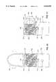
- FIG. 5is a side cross-sectional view of a defibrillator electrode system according to a preferred embodiment, prior to deployment.
- FIG. 6is a cross-sectional view of a connector between an electrode system and an instrument.
- FIG. 7is a side cross-sectional view of the defibrillator electrode system of FIG. 5 with one electrode partially deployed.
- FIG. 8is an elevational view of an alternative embodiment of the electrode system of this invention.
- FIG. 9is an exploded view of the electrode system of FIG. 8.
- FIG. 10is a side cross-sectional view of the embodiment of FIG. 8, prior to deployment.
- FIG. 11is a side cross-sectional view of the electrode system of FIG. 10 with the electrodes partially deployed.
- FIG. 1is a block diagram demonstrating the method and apparatus of this invention as applied to a defibrillator system.
- the defibrillator system 10includes two or more electrodes 12 selectively connected to a standard defibrillator circuit 14 through an electrode interface 16.
- the defibrillator circuitapplies a therapeutic voltage or current pulse to a patient through the electrodes under conditions controlled by logic within or associated with the circuit.
- the defibrillatormay also receive information regarding the patient's heart activity from the electrodes in the form of ECG signals.
- the electrodesmay be configured as described below or, alternatively, may be any defibrillator electrodes known in the art.
- a patient simulator 18is also selectively connected to the electrodes through interface 16.
- a defibrillator system analyzer 20connected to the defibrillator circuit 14 and the patient simulator 18 controls the operation of the defibrillator circuit 14 during a test procedure, receives test information through the patient simulator 18, analyzes the test information, and indicates the test results via indicator 22.
- a power source 24supplies power to the system.
- the operation of the system of FIG. 1is as follows.
- the systemmay be used to test the ability of the defibrillator circuit and electrodes to deliver a defibrillation pulse to a patient.
- Conductors leading from at least two electrodesare connected to the defibrillator circuit via an electrode interface.
- the electrode surfaces themselvesi.e., the portion of the electrodes that would be mounted on the patient during normal operation of the defibrillator, are electrically connected to the patient simulator, also via the electrode interface.
- a defibrillator test pulseis delivered from the defibrillator circuit to the electrodes, and the effect of the test pulse is measured at the patient simulator by the analyzer.
- the test pulsemay be a voltage pulse of any magnitude, including but not limited to voltage magnitudes used for actual defibrillation. In that case, the analyzer will measure the current flowing through the patient simulator.
- the test pulsemay also be a current pulse of any magnitude, in which case the analyzer will measure the voltage across the patient simulator. Other suitable tests will be apparent to those skilled in the art.
- the analyzeractivates the indicator to show that the defibrillator is not operable.
- the indicatormay be a visible indicator such as a light or a written message on a display, an audible sound, or any other suitable means of communicating an inoperable condition to the user.
- the systemmay also be used to test the response of the logic portion of the defibrillator circuit to a signal originating with the patient.
- conductors leading from at least two electrodesare connected to the defibrillator circuit via an electrode interface.
- the electrode surfaces themselvesi.e., the portion of the electrodes that would be mounted on the patient during normal operation of the defibrillator, are electrically connected to the patient simulator, also via the electrode interface.
- a signal substantially similar to an ECG signal derived from a patient in ventricular fibrillationis generated by the patient simulator and delivered to the defibrillator circuit via the electrodes and electrode interface. In normal operation, the defibrillator should deliver a defibrillation pulse to the patient in response to such an ECG signal.
- the ECG testmay also be used to determine the response of the defibrillator circuit to a normal (non-fibrillating) ECG signal from a patient.
- conductors leading from at least two electrodesare connected to the defibrillator circuit via an electrode interface.
- the electrode surfaces themselvesi.e., the portion of the electrodes that would be mounted on the patient during normal operation of the defibrillator, are electrically connected to the patient simulator via the electrode interface.
- a signal substantially similar to an ECG signal derived from a patient with a normal ECG, i.e., not in ventricular fibrillation,is generated by the patient simulator and delivered to the defibrillator circuit via the electrodes and electrode interface. In normal operation, the defibrillator should not deliver a defibrillation pulse to the patient in response to such an ECG signal.
- the analyzermonitors the output of the defibrillator circuit logic to the test ECG signal. If the defibrillator circuit logic indicates that a defibrillation pulse is required, then the analyzer activates the indicator to show that the defibrillator is not operable.
- the indicatormay be a visible indicator such as a light or a written message on a display, an audible sound, or any other suitable means of communicating an inoperable condition to the user.
- the frequency of any of these testsmay be chosen to meet the system's requirements.
- the power required for the defibrillator pulse testsmay be so high that the frequency of this test must be limited in order to preserve battery life in battery-operated defibrillators.
- the analyzercould monitor battery level continuously.
- FIG. 2is a circuit schematic showing one way of implementing the principal elements of the defibrillator system of the preferred embodiment.
- the portion of the schematic corresponding to the electrodes and electrode interface blocks of FIG. 1is enclosed by a dotted line 202 and is referred to as the electrode apparatus or electrode system.
- the electrode apparatus 202includes a pair of electrodes 204, conductive gel layers 206 covering the electrodes, and a pair of test pads or contacts 208 shown here to be in electrical contact with gel layers 206.
- the defibrillator system of this inventionhas a patient simulation and test circuit 220 to monitor the condition and integrity of the system prior to deployment of the electrodes and application of the electrodes to a patient.
- microprocessor 218sends a series of test signals to D/A converter 222, which converts the signals to their analog equivalent and transmits the signals to test pads 208 via conductors 224.
- Electrodes 204retrieve the test signals as if the test signals were actual patient ECG signals and sends the signals back to the microprocessor through the ECG monitor circuit described above.
- the microprocessordetermines from the incoming test ECG signal that a therapeutic pulse is not required, the system is faulty, and the microprocessor indicates the fault on a fault indicator 226. If, on the other hand, the microprocessor determines correctly the required course of action, the fault indicator is not activated.
- the systemIf the system passes the ECG tests, it then performs a defibrillator test by generating a pulse through its normal pulse generating circuitry and sending the pulse to the electrodes 204.
- the microprocessorsends a charge command to a charge controller 230, which begins charging capacitor 232 in a known manner from power supply 234.
- a charge controller 230which begins charging capacitor 232 in a known manner from power supply 234.
- switch relay 228moves switches 212 to their other position. This switch position permits the pulse circuit to discharge the capacitor to deliver a damped sinusoidal shock to the electrodes.
- the pulse transmitted by the electrodes through conductive gel layers 206 to test pads 208is monitored by the test circuit 220 across a patient load simulator 236.
- the signalis reduced by a divider circuit and sent to microprocessor 218 via A/D converter 238. If the pulse received by the microprocessor does not meet predetermined criteria (such as voltage levels and signal waveform shape), the microprocessor indicates a system fault by activating fault indicator 226. So long as the system passes the tests, the tests are repeated periodically until the electrodes and their gel layers are removed from test pads 208 as determined by a deployment detector 240.
- Electrode disk 44is disposed within electrode body 45.
- Electrode disk 44is preferably a circular piece of metal foil, such as 3 mil tin, approximately 80 cm 2 in area, attached to substrate 42 with a suitable medical grade adhesive.
- Electrode disk 44is covered with a layer of conductive gel 51 in a known manner. The thickness of gel layer 51 is 25 mils to make its top surface approximately even with the surrounding electrode body surface.
- Medical grade adhesiveis disposed in adhesive area 52 on the top surface of electrode body 45 surrounding the opening 53 for electrode disk 44.
- a first conductor 46 and a first electrical attachment pad 48are formed on, or attached to, flexible substrate 42.
- Conductor 46 and electrical attachment pad 48are preferably 3 mil tin foil formed integrally with electrode disk 44 and attached to substrate 42 with adhesive.
- a second conductor 43, a second electrical attachment pad 41 and a test pad 38are formed on, or attached to, substrate 42.
- Conductor 43, attachment pad 41 and test pad 38are also preferably formed as an integral piece of metal foil attached to substrate 42 with adhesive.
- An insulating cover 47is adhesively attached over substrate 42 and conductors 43 and 46.
- Cover 47has a silicon release coating on its top side. Openings 49 and 37 are formed in cover 47 so that attachment pads 48 and 41, respectively, can make electrical contact with a connector, as described below.
- An additional opening 39is formed in cover 47 so that test pad can make electrical contact with electrode 44 through gel 51, also as described below.
- FIGS. 5-7a pair of the electrodes shown in FIGS. 3 and 4 are mounted in a retainer for use with a defibrillator system.
- FIG. 5shows the electrodes in a predeployment storage position. In this position, the flexible substrate 42 of each electrode is folded in an accordion fashion and placed in retainer 60.
- FIG. 6shows the details of one embodiment of the connectors for attachment pads 48 on the two electrode apparatuses. The same arrangement may be used for attachment pads 41.
- test pads 38, their associated conductors 43, their attachment pads 41, and the retainer connector 70serve as the interface between the electrodes and a patient simulator circuit within defibrillator 58 during the defibrillator system tests described above.
- An indicator 59such as a light or an audible annunciator is provided to inform the user of test results.
- the conductors 46 and attachment pads 48 on the substratesare the interface between the electrodes and the defibrillator for delivery of the defibrillating voltage pulse and/or for monitoring of the electrical activity of the patient's heart during normal operation of the defibrillator.
- the positions of the electrode apparatus during the two operational modeswill be explained with reference to FIGS. 5 and 7.
- the conductive gel 51 covering the electrode disk 44 of each electrode apparatuslies in electrical contact with its respective test pad 38. This contact closes the circuit going from one electrode through the patient simulation circuit to the other electrode so that the patient simulation tests can be performed.
- the adhesive surrounding the electrode disklies against an area 54 on the top surface of substrate 42.
- the top surface of substrate 42is coated with a suitable release coating such as silicon in at least release area 54.
- the release coatingenables the adhesive to peel away from substrate 42 during deployment of the electrode, as discussed below.
- the covering action of the substrate over the conductive gelalso helps keep the conductive gel from drying out during storage.
- a handle 56 attached to the back side of electrode body 45lies in position in which it can be grasped by a user during deployment of the electrodes.
- FIG. 7demonstrates deployment of the electrodes.
- the userpulls electrode body 45 out of retainer 60 by grasping handle 56.
- the electrode disk 44 and its conductive gel layer 51peel away from substrate surface 42. Movement of the conductive gel layers 51 of the electrodes away from their respective test pads 38 breaks the circuit through the patient simulator.
- the electrodesmay be placed on a patient and used for monitoring the patient's heart activity and for applying therapeutic electrical pulses in the usual manner.
- FIGS. 8-11show an alternative embodiment of this invention.
- the electrode apparatus 140has a flexible body or substrate 142, preferably formed from 1/16" closed cell foam.
- a backing layer 182is attached to the underside of substrate 142 with a medical grade adhesive.
- Backing layer 182may be formed from Tyvek or any other suitable material.
- the underside of backing layer 182is coated with a silicon release material.
- a pair of test pads 138are adhesively attached to the top of backing layer 182 over a pair of openings 184 whose diameters are slightly smaller than the diameters of test pads 138. Openings 184 provide access to test pads 138 from the underside of backing layer 182.
- Conductors 143lead from test pads 138 to attachment pads 141. Openings 186 beneath attachment pads 141 have diameters slightly smaller than the diameters of attachment pads 141.
- Each set of test pad, conductor and attachment padis preferably formed from a single piece of tin metal foil 3 mils thick.
- a pair of electrodes 144are adhesively attached to the top of substrate 142.
- Conductors 146lead from electrodes 144 to attachment pads 148.
- Each set of electrode, conductor and attachment padis preferably formed from a single piece of tin metal foil 3 mils thick.
- the surface area of each electrodeis preferably 80 cm 2 .
- a layer of conductive gel 151covers each electrode. The thickness of the conductive gel layer is preferably 25 mils.
- An insulating cover 147is attached to the top side of substrate 142 with medical grade adhesive.
- Cover 147has openings 180 for the electrodes and openings 149 for the attachment pads. Openings 180 have diameters slightly smaller than the diameters of their respective electrodes, and openings 149 have diameters slightly smaller than their respective attachment pads.
- Medical grade adhesivecovers all of the top surface of cover 147 except for handle area 156 and connector area 157 for attachment of the electrode apparatus to a patient.
- FIGS. 10 and 11show the electrode apparatus of this embodiment mounted in a retainer.
- the electrode apparatusprior to deployment, the electrode apparatus is wound around a spool-shaped retainer 160 mounted on top of a defibrillator 158.
- the portion of the electrode apparatus on which the attachment pads 141 and 148 are locatedextend into the center of the retainer spool where they make electrical connection with conductors (not shown) that connect to the defibrillator connector 172.
- the metal crimps shown in FIG. 6may be used for this purpose.
- a protective cover 164may be kept over retainer spool 160 until the electrodes are to be deployed.
- the conductive gel layers 151 and the adhesive coating on cover layer 147face the inward toward the center of the retainer spool, and the release coating on the underside of backing layer 182 faces outward from the center.
- the conductive gel layers 151 and the adhesive coating on the cover layerlie against the silicon release coating of the backing layer 182.
- the conductive gel layers 151 of each electrodelie in electrical contact against their respective test pads 138, as shown. This contact closes the circuit going from one electrode through the patient simulation circuit to the other electrode so that the patient simulation tests can be performed.
- An indicator 159such as a light or an audible annunciator is provided to inform the user of test results.
- the protective cover 164is removed, and the electrode apparatus is unwound from retainer spool 160 by pulling on handle or tab 156, as shown in FIG. 11.
- the release coating on backing layer 182permits the conductive gel layers 151 and the adhesive on cover layer 147 to peel away. Movement of the conductive gel layers 151 of the electrodes away from their respective test pads 138 breaks the circuit through the patient simulator.
- the electrode apparatusis then applied to the patient and used for monitoring the patient's heart activity and for applying therapeutic electrical pulses in the usual manner.
- the electrode apparatus and spool retainerremain attached to the defibrillator during use.
- the conductors 146 and attachment pads 148provide the electrical connection between the electrodes 144 and the defibrillator for delivery of the defibrillating voltage pulse and/or for monitoring of the electrical activity of the patient's heart.
- the retainer spool and the electrode apparatus it housescan be discarded and replaced with a new electrode set.
Landscapes
- Health & Medical Sciences (AREA)
- Engineering & Computer Science (AREA)
- Biomedical Technology (AREA)
- Nuclear Medicine, Radiotherapy & Molecular Imaging (AREA)
- Radiology & Medical Imaging (AREA)
- Life Sciences & Earth Sciences (AREA)
- Animal Behavior & Ethology (AREA)
- General Health & Medical Sciences (AREA)
- Public Health (AREA)
- Veterinary Medicine (AREA)
- Cardiology (AREA)
- Heart & Thoracic Surgery (AREA)
- Electrotherapy Devices (AREA)
- Investigating Or Analysing Biological Materials (AREA)
Abstract
Description
Claims (11)
Priority Applications (2)
| Application Number | Priority Date | Filing Date | Title |
|---|---|---|---|
| US08/467,062US6016059A (en) | 1993-05-18 | 1995-06-06 | Defibrillator system condition indicator |
| US08/678,012US6075369A (en) | 1993-05-18 | 1996-07-10 | Defibrillator system condition indicator with an electrode interface |
Applications Claiming Priority (2)
| Application Number | Priority Date | Filing Date | Title |
|---|---|---|---|
| US6363193A | 1993-05-18 | 1993-05-18 | |
| US08/467,062US6016059A (en) | 1993-05-18 | 1995-06-06 | Defibrillator system condition indicator |
Related Parent Applications (1)
| Application Number | Title | Priority Date | Filing Date |
|---|---|---|---|
| US6363193ADivision | 1993-05-18 | 1993-05-18 |
Related Child Applications (1)
| Application Number | Title | Priority Date | Filing Date |
|---|---|---|---|
| US08/678,012DivisionUS6075369A (en) | 1993-05-18 | 1996-07-10 | Defibrillator system condition indicator with an electrode interface |
Publications (1)
| Publication Number | Publication Date |
|---|---|
| US6016059Atrue US6016059A (en) | 2000-01-18 |
Family
ID=22050487
Family Applications (6)
| Application Number | Title | Priority Date | Filing Date |
|---|---|---|---|
| US08/240,272Expired - LifetimeUS5879374A (en) | 1993-05-18 | 1994-05-10 | External defibrillator with automatic self-testing prior to use |
| US08/467,231Expired - LifetimeUS5617853A (en) | 1993-05-18 | 1995-06-06 | Defibrillator electrode system using a flexible substrate and having electrode test features |
| US08/467,062Expired - LifetimeUS6016059A (en) | 1993-05-18 | 1995-06-06 | Defibrillator system condition indicator |
| US08/532,863Expired - LifetimeUS5591213A (en) | 1993-05-18 | 1995-09-21 | Defibrillator system condition indictator |
| US08/678,012Expired - LifetimeUS6075369A (en) | 1993-05-18 | 1996-07-10 | Defibrillator system condition indicator with an electrode interface |
| US08/834,346Expired - LifetimeUS5800460A (en) | 1993-05-18 | 1997-04-16 | Method for performing self-test in a defibrillator |
Family Applications Before (2)
| Application Number | Title | Priority Date | Filing Date |
|---|---|---|---|
| US08/240,272Expired - LifetimeUS5879374A (en) | 1993-05-18 | 1994-05-10 | External defibrillator with automatic self-testing prior to use |
| US08/467,231Expired - LifetimeUS5617853A (en) | 1993-05-18 | 1995-06-06 | Defibrillator electrode system using a flexible substrate and having electrode test features |
Family Applications After (3)
| Application Number | Title | Priority Date | Filing Date |
|---|---|---|---|
| US08/532,863Expired - LifetimeUS5591213A (en) | 1993-05-18 | 1995-09-21 | Defibrillator system condition indictator |
| US08/678,012Expired - LifetimeUS6075369A (en) | 1993-05-18 | 1996-07-10 | Defibrillator system condition indicator with an electrode interface |
| US08/834,346Expired - LifetimeUS5800460A (en) | 1993-05-18 | 1997-04-16 | Method for performing self-test in a defibrillator |
Country Status (3)
| Country | Link |
|---|---|
| US (6) | US5879374A (en) |
| AT (1) | ATE487511T1 (en) |
| DE (2) | DE69435324D1 (en) |
Cited By (25)
| Publication number | Priority date | Publication date | Assignee | Title |
|---|---|---|---|---|
| US6577102B1 (en) | 2001-09-21 | 2003-06-10 | Defibtech Llc | Medical device battery system including a secondary power supply |
| EP1382369A1 (en) | 2002-07-20 | 2004-01-21 | Schiller AG | Device for electrotherapy and method of testing and operating the same |
| US20040249417A1 (en)* | 2003-06-04 | 2004-12-09 | Terrance Ransbury | Implantable intravascular device for defibrillation and/or pacing |
| US20040249431A1 (en)* | 2003-06-04 | 2004-12-09 | Terrance Ransbury | Device and method for retaining a medical device within a vessel |
| US20050154437A1 (en)* | 2003-12-12 | 2005-07-14 | Williams Michael S. | Implantable medical device having pre-implant exoskeleton |
| US20050228471A1 (en)* | 2003-06-04 | 2005-10-13 | Williams Michael S | Method and apparatus for retaining medical implants within body vessels |
| US6955864B1 (en) | 2001-09-21 | 2005-10-18 | Defibtech, Llc | Medical device battery pack with active status indication |
| US20050234431A1 (en)* | 2004-02-10 | 2005-10-20 | Williams Michael S | Intravascular delivery system for therapeutic agents |
| US20060259080A1 (en)* | 2005-03-21 | 2006-11-16 | Defibtech, Llc | System and method for presenting defibrillator status information while in standby mode |
| US20080077219A1 (en)* | 2003-06-04 | 2008-03-27 | Williams Michael S | Intravascular electrophysiological system and methods |
| US20080136652A1 (en)* | 2006-03-21 | 2008-06-12 | Defibtech, Llc | System and Method for Effectively Indicating Element Failure or a Preventive Maintenance Condition in an Automatic External Defibrillator (AED) |
| US20080183089A1 (en)* | 2007-01-31 | 2008-07-31 | Greeninger Daniel R | Tissue ingrowth enhancement for shroud-based plate electrodes configured for chronic implantation |
| US7548781B2 (en) | 2005-03-21 | 2009-06-16 | Defibtech, Llc | Environmentally responsive active status indicator system and method |
| US20090187225A1 (en)* | 2005-03-21 | 2009-07-23 | Defibtech, Llc | PCB blade connector system and method |
| US20100152795A1 (en)* | 2008-12-11 | 2010-06-17 | Pacesetter, Inc. | Identification of dysynchrony using intracardiac electrogram data |
| US7930023B2 (en) | 2001-09-21 | 2011-04-19 | Defibtech, Llc | Automatic external defibrillator with active status indicator |
| WO2013040214A1 (en)* | 2011-09-15 | 2013-03-21 | Zoll Medical Corporation | Testing electrical connections between cardiac resuscitation devices and external electrodes |
| US8996138B2 (en) | 2006-07-05 | 2015-03-31 | Zoll Medical Corporation | Breakaway electrical connections for defibrillation electrode package |
| US20160008616A1 (en)* | 2009-02-20 | 2016-01-14 | Barry Schwibner | Adaptation Of The Common Notebook, Laptop Computer, Netbook and Tablet Computer To Enable Each To Be Used As An Automated External Defibrillator (AED) To Treat Victims Of Sudden Cardiac Arrest |
| US9517354B2 (en) | 2009-02-20 | 2016-12-13 | Comptolife, Llc | Pocket kits and methods for retrofitting and adapting common notebook computers, laptop computers, and tablet computers, to enable each to be used as an automated external defibrillator (AED), and as a manual defibrillator |
| US9757576B2 (en) | 2014-03-18 | 2017-09-12 | West Affum Holdings Corp. | Reliable readiness indication for a wearable defibrillator |
| US10029109B2 (en) | 2016-12-12 | 2018-07-24 | Revive Solutions, Inc. | Defibrillator |
| US10449380B2 (en) | 2016-12-12 | 2019-10-22 | Revive Solutions, Inc. | Defibrillator |
| US10903675B2 (en) | 2016-12-12 | 2021-01-26 | Avive Solutions, Inc. | Medical device draw current regulation |
| US11607555B2 (en) | 2016-12-12 | 2023-03-21 | Avive Solutions, Inc. | Defibrillator discharge control |
Families Citing this family (190)
| Publication number | Priority date | Publication date | Assignee | Title |
|---|---|---|---|---|
| US5579234A (en)* | 1994-03-11 | 1996-11-26 | Physio-Control Corporation | System for automatically testing an electronic device during quiescent periods |
| US5797969A (en)* | 1995-08-01 | 1998-08-25 | Survivalink Corporation | One button lid activated automatic external defibrillator |
| US5967817A (en) | 1995-11-21 | 1999-10-19 | Heartstream, Inc. | Medical connector apparatus |
| WO1997043000A1 (en)* | 1996-05-10 | 1997-11-20 | Survivalink Corporation | Defibrillator electrode circuitry |
| US5700281A (en)* | 1996-06-04 | 1997-12-23 | Survivalink Corporation | Stage and state monitoring automated external defibrillator |
| US5697955A (en)* | 1996-05-10 | 1997-12-16 | Survivalink Corporation | Defibrillator electrodes and date code detector circuit |
| US6101413A (en)* | 1996-06-04 | 2000-08-08 | Survivalink Corporation | Circuit detectable pediatric defibrillation electrodes |
| US5773961A (en)* | 1996-06-06 | 1998-06-30 | Heartstream, Inc. | Dynamic load controller for a battery |
| US6021352A (en)* | 1996-06-26 | 2000-02-01 | Medtronic, Inc, | Diagnostic testing methods and apparatus for implantable therapy devices |
| US5993219A (en)* | 1996-11-05 | 1999-11-30 | Heartstream, Inc. | Method and apparatus for modifying a resuscitation training mannequin |
| US6175765B1 (en)* | 1997-03-05 | 2001-01-16 | Medtronic Physio-Control Manufacturing Corp. | H-bridge circuit for generating a high-energy biphasic waveform in an external defibrillator |
| US5824017A (en)* | 1997-03-05 | 1998-10-20 | Physio-Control Corporation | H-bridge circuit for generating a high-energy biphasic waveform in an external defibrillator |
| US5873893A (en)* | 1997-03-05 | 1999-02-23 | Physio-Control Corporation | Method and apparatus for verifying the integrity of an output circuit before and during application of a defibrillation pulse |
| US6963773B2 (en)* | 1997-03-05 | 2005-11-08 | Medtronic Physio-Control Manufacturing Corp. | H-bridge circuit for generating a high-energy biphasic waveform in an external defibrillator using single SCR and IGBT switches in an integrated package |
| US6148233A (en) | 1997-03-07 | 2000-11-14 | Cardiac Science, Inc. | Defibrillation system having segmented electrodes |
| US5899925A (en)* | 1997-08-07 | 1999-05-04 | Heartstream, Inc. | Method and apparatus for aperiodic self-testing of a defibrillator |
| US5904707A (en)* | 1997-08-15 | 1999-05-18 | Heartstream, Inc. | Environment-response method for maintaining an external medical device |
| US5868792A (en)* | 1997-08-15 | 1999-02-09 | Heartstream, Inc. | Environment-response method for maintaining electronic device such as an external defibrillator |
| US6631293B2 (en)* | 1997-09-15 | 2003-10-07 | Cardiac Pacemakers, Inc. | Method for monitoring end of life for battery |
| US6167309A (en)* | 1997-09-15 | 2000-12-26 | Cardiac Pacemakers, Inc. | Method for monitoring end of life for battery |
| SE9704521D0 (en) | 1997-12-04 | 1997-12-04 | Pacesetter Ab | Medical implant |
| US6115638A (en)* | 1998-05-04 | 2000-09-05 | Survivalink Corporation | Medical electrode with conductive release liner |
| US7171265B2 (en)* | 1998-07-31 | 2007-01-30 | Harbinger Medical, Inc. | Apparatus and method for detecting lead adequacy and quality |
| US6108578A (en)* | 1998-09-02 | 2000-08-22 | Heartstream, Inc. | Configurable arrhythmia analysis algorithm |
| US6141584A (en)* | 1998-09-30 | 2000-10-31 | Agilent Technologies, Inc. | Defibrillator with wireless communications |
| US6208895B1 (en)* | 1998-10-13 | 2001-03-27 | Physio-Control Manufacturing Corporation | Circuit for performing external pacing and biphasic defibrillation |
| US6125299A (en) | 1998-10-29 | 2000-09-26 | Survivalink Corporation | AED with force sensor |
| US6128528A (en)* | 1999-03-18 | 2000-10-03 | Medtronics, Inc. | Error code calculations for data stored in an implantable medical device |
| US6234816B1 (en) | 1999-03-30 | 2001-05-22 | Agilant Technologies, Inc. | Medical connector apparatus |
| US6658291B2 (en)* | 1999-04-08 | 2003-12-02 | Koninklijke Philips Electronics N.V. | Electrode system for improved detection of pad contact and artifact detection or removal |
| US6185458B1 (en) | 1999-04-30 | 2001-02-06 | Agilent Technologies, Inc. | Reduced energy self test operation in a defibrillator |
| US6266562B1 (en) | 1999-04-30 | 2001-07-24 | Agilent Technologies, Inc. | Defibrillator with automated test load |
| EP1050269A1 (en)* | 1999-05-07 | 2000-11-08 | Nessler Medizintechnik GmbH & Co KG | Multiple-contact electrode |
| WO2000070889A1 (en)* | 1999-05-14 | 2000-11-23 | Medtronic Physio-Control Manufacturing Corp. | Method and apparatus for remote wireless communication with a medical device |
| US6314320B1 (en) | 1999-10-01 | 2001-11-06 | Daniel J Powers | Method and apparatus for selectively inactivating AED functionality |
| US6438415B1 (en) | 1999-10-01 | 2002-08-20 | Daniel J Powers | Method and apparatus for controlling the operation and functionality of an electrotherapy device |
| US6360120B1 (en) | 1999-10-13 | 2002-03-19 | Daniel J Powers | Method and apparatus for transferring patient data generated by an external defibrillator |
| US6304783B1 (en) | 1999-10-14 | 2001-10-16 | Heartstream, Inc. | Defibrillator system including a removable monitoring electrodes adapter and method of detecting the monitoring adapter |
| US6990371B2 (en)* | 1999-10-14 | 2006-01-24 | Koninklijke Philips Electronics N.V. | Method and apparatus for providing on-screen incident review in an AED |
| US20060064131A1 (en)* | 2000-02-04 | 2006-03-23 | Freeman Gary A | User interface for defibrillator for use by persons with limited training and experience |
| JP2003521355A (en) | 2000-02-04 | 2003-07-15 | ゼットエムデー コーポレイション | Integrated resuscitation |
| US20050131465A1 (en) | 2000-02-04 | 2005-06-16 | Freeman Gary A. | Integrated resuscitation |
| US6329822B1 (en) | 2000-02-11 | 2001-12-11 | Daniel J. Powers | Periodic automatic self-test system and methodology |
| US7016726B1 (en) | 2000-05-17 | 2006-03-21 | Koninklijke Philips Electronics N.V. | Smart medical connector system and method of use |
| US6714824B1 (en) | 2000-05-26 | 2004-03-30 | Koninklijke Philips Electronics N.V. | Universal electrode system and methods of use and manufacture |
| US6586850B1 (en) | 2000-07-05 | 2003-07-01 | Koninklijke Philips Electronics N.V. | Device with multiple, concurrently-installed power molecules and method for controlling same |
| US7463922B1 (en) | 2000-07-13 | 2008-12-09 | Koninklijke Philips Electronics, N.V. | Circuit and method for analyzing a patient's heart function using overlapping analysis windows |
| US6556864B1 (en) | 2000-11-13 | 2003-04-29 | Koninklijke Philips Electronics N.V. | Object activated defibrillator |
| US6694299B1 (en)* | 2000-12-14 | 2004-02-17 | Matthew Barrer | Method of implementing a cardiac emergency readiness program |
| US6675051B2 (en) | 2000-12-22 | 2004-01-06 | Koninklijke Philips Electronics N.V. | See-through electrode-pad package and method for using a storage system that includes the package |
| US6662056B2 (en) | 2000-12-22 | 2003-12-09 | Koninklijke Philips Electronics N.V. | Cartridge for storing an electrode pad |
| US6871093B2 (en) | 2000-12-28 | 2005-03-22 | Koninklijke Philips Electronics N.V. | Reporting the status for an external defibrillator with an audible report in response to a specified user input |
| US6493581B2 (en) | 2000-12-28 | 2002-12-10 | Koninklijke Philips Electronics N.V. | System and method for rapid recruitment of widely distributed easily operated automatic external defibrillators |
| US6546286B2 (en) | 2001-02-27 | 2003-04-08 | Koninklijke Philips Electronics N.V. | Battery-less, human-powered electrotherapy device |
| US6935889B2 (en)* | 2001-02-28 | 2005-08-30 | Koninklijke Philips Electronics N.V. | Electrode-pad package that is removable from an electrode-pad lead and method for opening the package |
| US6560485B2 (en) | 2001-03-27 | 2003-05-06 | Koninklijke Philips Electronics N.V. | Four contact identification defibrillator electrode system |
| US6584355B2 (en)* | 2001-04-10 | 2003-06-24 | Cardiac Pacemakers, Inc. | System and method for measuring battery current |
| US6671547B2 (en) | 2001-06-13 | 2003-12-30 | Koninklijke Philips Electronics N.V. | Adaptive analysis method for an electrotherapy device and apparatus |
| US7848805B2 (en)* | 2001-07-20 | 2010-12-07 | Koninklijke Philips Electronics N.V. | Modular medical device, base unit and module thereof, and automated external defibrillator (AED), methods for assembling and using the AED |
| US20030028219A1 (en) | 2001-07-20 | 2003-02-06 | Powers Daniel J. | Modular medical device, base unit and module thereof, and automated external defibrillator (AED), methods for assembling and using the AED |
| GB2418365B (en) | 2001-09-07 | 2006-06-14 | Desmond Bryan Mills | Contact electrode |
| US6782293B2 (en)* | 2001-09-14 | 2004-08-24 | Zoll Medical Corporation | Defibrillation electrode assembly including CPR pad |
| US7069074B2 (en) | 2001-11-07 | 2006-06-27 | Medtronic Emergency Response Systems, Inc. | Easy-to-use electrode and package |
| CA2466207A1 (en)* | 2001-11-02 | 2003-05-15 | Brent Taylor Hetherington | System and method for monitoring and ensuring proper life safety equipment maintenance, operation, and program implementation |
| US7016727B2 (en) | 2001-11-05 | 2006-03-21 | Koninklijke Philips Electronics N.V. | Cartridge having a power source and electrode pad for defibrillator having a rechargeable battery |
| GB0128431D0 (en)* | 2001-11-28 | 2002-01-16 | Ixa Group Ltd | Improvements in and relating to portable defibrillators |
| US6662046B2 (en) | 2001-12-21 | 2003-12-09 | Koninklijke Philips Electronics N.V. | Defibrillator with automatic turn on, defibrillator storage case, and related system and method |
| US20030117442A1 (en)* | 2001-12-26 | 2003-06-26 | Yuemean Chen | Dynamic indication for capacitor charging status |
| US6957368B2 (en)* | 2002-01-23 | 2005-10-18 | Medtronic Emergency Response Systems, Inc. | Hazard mitigation in medical device |
| KR100488516B1 (en)* | 2002-02-05 | 2005-05-11 | 삼성전자주식회사 | display apparatus and error detection method thereof |
| US7736237B2 (en) | 2002-03-01 | 2010-06-15 | Aegis Industries, Inc. | Electromuscular incapacitation device and methods |
| GB2386071B (en)* | 2002-03-09 | 2005-11-16 | Ixa Medical Products Llp | Medical device |
| US7096062B2 (en) | 2002-03-11 | 2006-08-22 | Medtronic Physio-Control Manufacturing Corp. | Method for self-test of defibrillation and pacing circuits including a patient isolation switch |
| US6965796B2 (en)* | 2002-03-11 | 2005-11-15 | Medtronic Physio-Control Manufacturing Corp. | Method and apparatus for self-test of defibrillation and pacing circuits including a patient isolation switch |
| US6980859B2 (en) | 2002-03-22 | 2005-12-27 | Koninklijke Philips Electronics N.V. | Automated external defibrillator with a plurality of power sources |
| US7120503B2 (en)* | 2002-04-08 | 2006-10-10 | Koninklijke Philips Electronics, N.V. | Sterile disposable internal defibrillation paddles |
| US6968230B2 (en)* | 2002-06-26 | 2005-11-22 | Medtronic Physio-Control Manufacturing Corp | H-bridge circuit for generating a high-energy biphasic and external pacing waveform in an external defibrillator |
| DE10235564A1 (en)* | 2002-08-03 | 2004-02-12 | Robert Bosch Gmbh | Watchdog circuit for microprocessor or microcontroller monitoring, has means for checking the watchdog circuit itself by resetting it and then executing a number of wait loops such that a processor monitoring time is exceeded |
| US20040044371A1 (en)* | 2002-09-04 | 2004-03-04 | Medtronic Physio-Control Manufacturing Corp. | Defibrillator with H-bridge output circuit referenced to common ground |
| USD524943S1 (en) | 2002-09-09 | 2006-07-11 | Zoll Medical Corporation | Defibrillator electrode assembly |
| US20040049233A1 (en)* | 2002-09-11 | 2004-03-11 | Edwards D. Craig | Medical device status information system |
| AU2003264833A1 (en)* | 2002-10-23 | 2004-05-13 | Denney, Douglas, Michael | Interactive automatic external defibrillator providing attachment guidance to operator |
| US6827695B2 (en) | 2002-10-25 | 2004-12-07 | Revivant Corporation | Method of determining depth of compressions during cardio-pulmonary resuscitation |
| US20040088011A1 (en)* | 2002-10-31 | 2004-05-06 | Koninklijke Philips Electronics N.V. | Defibrillation circuit that can compensate for a variation in a patient parameter and related defibrillator and method |
| DE10254480B4 (en)* | 2002-11-19 | 2007-12-27 | Metrax Gmbh | Method for verifying the operability of an externally applicable defibrillator |
| DE10254482B4 (en)* | 2002-11-19 | 2008-06-05 | Metrax Gmbh | defibrillator |
| JP4385245B2 (en)* | 2002-12-06 | 2009-12-16 | 日本光電工業株式会社 | Defibrillator |
| CA2508800A1 (en) | 2002-12-11 | 2004-06-24 | Proteus Biomedical, Inc. | Method and system for monitoring and treating hemodynamic parameters |
| AU2004206734B2 (en)* | 2003-01-17 | 2009-07-30 | Heartsine Technologies Limited | Disposable defibrillator electrode assembly |
| US20040162586A1 (en)* | 2003-02-18 | 2004-08-19 | Covey Kevin K. | Defibrillator electrodes with identification tags |
| US6961612B2 (en) | 2003-02-19 | 2005-11-01 | Zoll Medical Corporation | CPR sensitive ECG analysis in an automatic external defibrillator |
| GB2402747B (en)* | 2003-06-14 | 2007-05-09 | Desmond Bryan Mills | A medical device including a self test system |
| CN1756711A (en)* | 2003-06-18 | 2006-04-05 | 东芝电梯株式会社 | Sheaves for elevators |
| US7220235B2 (en)* | 2003-06-27 | 2007-05-22 | Zoll Medical Corporation | Method and apparatus for enhancement of chest compressions during CPR |
| WO2005000392A2 (en)* | 2003-06-27 | 2005-01-06 | Koninklijke Philips Electronics N.V. | Method of detecting when electrode pads have been handled or removed from their package |
| US7239146B2 (en)* | 2003-07-11 | 2007-07-03 | Cardiac Pacemakers, Inc. | Indicator of remaining energy in storage cell of implantable medical device |
| US20050065558A1 (en)* | 2003-09-19 | 2005-03-24 | Powers Daniel J. | External defibrillator having a removable battery pack using off-the-shelf cells |
| US6940255B2 (en)* | 2003-10-23 | 2005-09-06 | Cardiac Pacemakers, Inc. | Battery charge indicator such as for an implantable medical device |
| JP2012091021A (en) | 2003-11-06 | 2012-05-17 | Zoll Medical Corp | Device for analyzing physiological signal during application of chest compression |
| US20050101889A1 (en)* | 2003-11-06 | 2005-05-12 | Freeman Gary A. | Using chest velocity to process physiological signals to remove chest compression artifacts |
| US7194308B2 (en) | 2003-11-12 | 2007-03-20 | Cardiac Pacemakers, Inc. | System and method for monitoring or reporting battery status of implantable medical device |
| US7957798B2 (en) | 2003-12-17 | 2011-06-07 | Physio-Control, Inc. | Defibrillator/monitor system having a pod with leads capable of wirelessly communicating |
| US10413742B2 (en) | 2008-03-05 | 2019-09-17 | Physio-Control, Inc. | Defibrillator patient monitoring pod |
| WO2005112749A1 (en) | 2004-05-12 | 2005-12-01 | Zoll Medical Corporation | Ecg rhythm advisory method |
| US7565194B2 (en) | 2004-05-12 | 2009-07-21 | Zoll Medical Corporation | ECG rhythm advisory method |
| WO2006046160A1 (en)* | 2004-10-29 | 2006-05-04 | Koninklijke Philips Electronics, N.V. | Electrode and enclosure for cardiac monitoring and treatment |
| US10709330B2 (en)* | 2004-11-15 | 2020-07-14 | Koninklijke Philips N.V. | Ambulatory medical telemetry device having an audio indicator |
| WO2006055936A2 (en)* | 2004-11-18 | 2006-05-26 | Access Cardiosystems, Inc. | System and method for performing self-test in an automatic external defibrillator (afd) |
| CN101084040B (en) | 2004-12-20 | 2012-12-05 | 皇家飞利浦电子股份有限公司 | Automatic external defibrillator for adult and pediatric patients |
| CN101098730A (en) | 2005-01-05 | 2008-01-02 | 皇家飞利浦电子股份有限公司 | Defibrillator event data with time correlation |
| WO2006104977A2 (en)* | 2005-03-25 | 2006-10-05 | Zoll Medical Corporation | Integrated resuscitation |
| EP1871470A4 (en) | 2005-03-31 | 2011-06-01 | Proteus Biomedical Inc | Automated optimization of multi-electrode pacing for cardiac resynchronization |
| WO2007021804A2 (en) | 2005-08-12 | 2007-02-22 | Proteus Biomedical, Inc. | Evaluation of depolarization wave conduction velocity |
| US7650181B2 (en) | 2005-09-14 | 2010-01-19 | Zoll Medical Corporation | Synchronization of repetitive therapeutic interventions |
| US8224447B2 (en)* | 2005-11-30 | 2012-07-17 | Medtronic, Inc. | Medical device packaging system |
| US20070123947A1 (en)* | 2005-11-30 | 2007-05-31 | Wenger William K | Medical device packaging system |
| EP1986740A2 (en)* | 2006-02-15 | 2008-11-05 | Koninklijke Philips Electronics N.V. | Cpr assistance and effectiveness display |
| US8315693B2 (en) | 2006-02-28 | 2012-11-20 | Physio-Control, Inc. | Electrocardiogram monitoring |
| US7610176B2 (en)* | 2006-06-06 | 2009-10-27 | Palm, Inc. | Technique for collecting information about computing devices |
| US8577462B2 (en) | 2006-07-05 | 2013-11-05 | Zoll Medical Corporation | Condition sensor for medical device package |
| US7877139B2 (en) | 2006-09-22 | 2011-01-25 | Cameron Health, Inc. | Method and device for implantable cardiac stimulus device lead impedance measurement |
| US7764998B1 (en)* | 2006-12-05 | 2010-07-27 | Pacesetter, Inc. | Implantable cardiac stimulation devices with back-up defibrillation |
| US8473069B2 (en) | 2008-02-28 | 2013-06-25 | Proteus Digital Health, Inc. | Integrated circuit implementation and fault control system, device, and method |
| US20090227857A1 (en)* | 2008-03-06 | 2009-09-10 | Chuck Rowe | Biomedical electrode |
| US8548558B2 (en)* | 2008-03-06 | 2013-10-01 | Covidien Lp | Electrode capable of attachment to a garment, system, and methods of manufacturing |
| US9008766B2 (en)* | 2008-06-02 | 2015-04-14 | Physio-Control, Inc. | Medical device adjusting operation when used with non-authenticated patient parameter collecting accessory |
| US8081071B1 (en)* | 2008-08-25 | 2011-12-20 | Vaisnys Gintavas A | System and method for monitoring external portable medical devices |
| US8324902B2 (en)* | 2008-09-23 | 2012-12-04 | Aegis Industries, Inc. | Stun device testing apparatus and methods |
| US8868216B2 (en)* | 2008-11-21 | 2014-10-21 | Covidien Lp | Electrode garment |
| US20100198305A1 (en)* | 2009-01-30 | 2010-08-05 | Pavad Medical, Inc. | Detection of implant functionality |
| WO2010126503A1 (en)* | 2009-04-29 | 2010-11-04 | Proteus Biomedical, Inc. | Methods and apparatus for leads for implantable devices |
| WO2011011736A2 (en) | 2009-07-23 | 2011-01-27 | Proteus Biomedical, Inc. | Solid-state thin film capacitor |
| US8565871B2 (en) | 2009-09-07 | 2013-10-22 | Qualcomm Incorporated | Automated external defibrillator device with integrated wireless modem |
| DE102010024566A1 (en)* | 2010-06-10 | 2011-12-15 | Repower Systems Ag | Wind turbine and method for testing a speed relay of a wind turbine |
| US8718770B2 (en) | 2010-10-21 | 2014-05-06 | Medtronic, Inc. | Capture threshold measurement for selection of pacing vector |
| CN103200989B (en)* | 2010-11-11 | 2015-08-05 | 皇家飞利浦电子股份有限公司 | There is the defibrillator suitcase of integral button tester |
| US8355784B2 (en) | 2011-05-13 | 2013-01-15 | Medtronic, Inc. | Dynamic representation of multipolar leads in a programmer interface |
| GB2491171B (en)* | 2011-05-26 | 2016-09-28 | Heartsine Tech Ltd | Testing of defibrillator electrodes |
| GB2494861A (en) | 2011-09-15 | 2013-03-27 | Heartsine Technologies Ltd | Defibrillator electrode test system |
| US8965506B2 (en)* | 2011-12-22 | 2015-02-24 | Medtronic, Inc. | Fault tolerant pacing |
| WO2013128306A1 (en) | 2012-02-28 | 2013-09-06 | Koninklijke Philips N.V. | Combined aed and cpr delivery assistance unit |
| US9126055B2 (en) | 2012-04-20 | 2015-09-08 | Cardiac Science Corporation | AED faster time to shock method and device |
| US9289621B2 (en) | 2012-05-08 | 2016-03-22 | Physio-Control, Inc. | Defibrillator network system |
| US20130307550A1 (en)* | 2012-05-18 | 2013-11-21 | O2Micro Inc. | State of charge indicators for battery packs |
| US20140002241A1 (en) | 2012-06-29 | 2014-01-02 | Zoll Medical Corporation | Response system with emergency response equipment locator |
| US10303852B2 (en) | 2012-07-02 | 2019-05-28 | Physio-Control, Inc. | Decision support tool for use with a medical monitor-defibrillator |
| US8812125B2 (en) | 2012-08-31 | 2014-08-19 | Greatbatch Ltd. | Systems and methods for the identification and association of medical devices |
| US9471753B2 (en) | 2012-08-31 | 2016-10-18 | Nuvectra Corporation | Programming and virtual reality representation of stimulation parameter Groups |
| US8761897B2 (en) | 2012-08-31 | 2014-06-24 | Greatbatch Ltd. | Method and system of graphical representation of lead connector block and implantable pulse generators on a clinician programmer |
| US8903496B2 (en) | 2012-08-31 | 2014-12-02 | Greatbatch Ltd. | Clinician programming system and method |
| US9615788B2 (en) | 2012-08-31 | 2017-04-11 | Nuvectra Corporation | Method and system of producing 2D representations of 3D pain and stimulation maps and implant models on a clinician programmer |
| US9507912B2 (en) | 2012-08-31 | 2016-11-29 | Nuvectra Corporation | Method and system of simulating a pulse generator on a clinician programmer |
| US9375582B2 (en) | 2012-08-31 | 2016-06-28 | Nuvectra Corporation | Touch screen safety controls for clinician programmer |
| US8868199B2 (en) | 2012-08-31 | 2014-10-21 | Greatbatch Ltd. | System and method of compressing medical maps for pulse generator or database storage |
| US10668276B2 (en) | 2012-08-31 | 2020-06-02 | Cirtec Medical Corp. | Method and system of bracketing stimulation parameters on clinician programmers |
| US9594877B2 (en) | 2012-08-31 | 2017-03-14 | Nuvectra Corporation | Virtual reality representation of medical devices |
| US9259577B2 (en) | 2012-08-31 | 2016-02-16 | Greatbatch Ltd. | Method and system of quick neurostimulation electrode configuration and positioning |
| US9180302B2 (en) | 2012-08-31 | 2015-11-10 | Greatbatch Ltd. | Touch screen finger position indicator for a spinal cord stimulation programming device |
| US8983616B2 (en) | 2012-09-05 | 2015-03-17 | Greatbatch Ltd. | Method and system for associating patient records with pulse generators |
| US8757485B2 (en) | 2012-09-05 | 2014-06-24 | Greatbatch Ltd. | System and method for using clinician programmer and clinician programming data for inventory and manufacturing prediction and control |
| US9767255B2 (en) | 2012-09-05 | 2017-09-19 | Nuvectra Corporation | Predefined input for clinician programmer data entry |
| BR112015013795A2 (en) | 2012-12-17 | 2017-07-11 | Koninklijke Philips Nv | method for performing the self-test of a defibrillator, and defibrillator that has an automatic self-test protocol |
| US9808639B2 (en)* | 2012-12-26 | 2017-11-07 | Koninklijke Philips N.V. | Intuitive overlaid readiness indicator for defibrillators |
| EP2969034A4 (en) | 2013-03-15 | 2016-11-30 | Zoll Medical Corp | IMPEDANCE SIGNAL PROCESSING FOR BREATHING DETECTION |
| EP2967394A4 (en) | 2013-03-15 | 2016-11-09 | Zoll Medical Corp | Ecg noise reduction system for removal of vehicle motion artifact |
| US20140323928A1 (en) | 2013-04-30 | 2014-10-30 | Zoll Medical Corporation | Compression Depth Monitor with Variable Release Velocity Feedback |
| AU2014292850B2 (en) | 2013-07-25 | 2019-04-11 | Physio-Control, Inc. | Electrode assembly having various communicative solutions |
| JP2016531663A (en) | 2013-08-01 | 2016-10-13 | ゾール メディカル コーポレイションZOLL Medical Corporation | System and method for utilizing an identification device in a wearable medical treatment device |
| US10213124B2 (en)* | 2013-09-25 | 2019-02-26 | Zoll Medical Corporation | Electrocardiogram package |
| US20150088016A1 (en) | 2013-09-25 | 2015-03-26 | Zoll Medical Corporation | Mobile Device Control |
| TWI609259B (en)* | 2014-01-08 | 2017-12-21 | 宏碁股份有限公司 | Charging indication apparatus and method thereof |
| US10596064B2 (en) | 2014-03-18 | 2020-03-24 | Zoll Medical Corporation | CPR chest compression system with tonometric input and feedback |
| EP3122423B1 (en) | 2014-03-27 | 2021-06-16 | Koninklijke Philips N.V. | Encoded status indicator for automated external defibrillators |
| US10268229B2 (en) | 2014-12-23 | 2019-04-23 | Zoll Medical Corporation | Adjustable electrical equipment |
| WO2016160369A1 (en) | 2015-03-20 | 2016-10-06 | Zoll Medical Corporation | Systems for self-testing an ambulatory medical device |
| EP3673953B1 (en) | 2015-03-27 | 2022-09-14 | Zoll Medical Corporation | Ecg and defibrillator electrode detection and tracking system |
| CN108136192A (en) | 2015-10-16 | 2018-06-08 | Zoll医疗公司 | For providing the dual sensor electrode of the recovery feedback of enhancing |
| US11709747B2 (en) | 2016-01-08 | 2023-07-25 | Zoll Medical Corporation | Patient assurance system and method |
| US10006738B2 (en) | 2016-01-08 | 2018-06-26 | Randall T. Stoppenhagen | Archery hand warming device |
| US10561852B2 (en) | 2016-02-26 | 2020-02-18 | Zoll Medical Corporation | Systems and methods for providing rapid medical care |
| US10729900B2 (en)* | 2016-03-29 | 2020-08-04 | Zoll Medical Corporation | Configurable electrodes and sensors |
| US10426342B2 (en) | 2016-03-31 | 2019-10-01 | Zoll Medical Corporation | Remote access for ambulatory medical device |
| RU2019114363A (en) | 2016-10-12 | 2020-11-13 | Конинклейке Филипс Н.В. | SUPPRESSING AN AUTOMATED EXTERNAL DEFIBRILLATOR (AED) TEST WARNING |
| US11672484B2 (en) | 2016-12-16 | 2023-06-13 | Zoll Medical Corporation | Electrode falloff detection |
| WO2018182771A1 (en)* | 2017-03-30 | 2018-10-04 | Axon Enterprise, Inc. | Systems and methods for calibrating a tester for a conducted electrical weapon |
| US11185708B2 (en) | 2017-10-18 | 2021-11-30 | Rescuestat Llc | Heartstation remote monitor system |
| CN107831418A (en)* | 2017-10-27 | 2018-03-23 | 深圳迈瑞生物医疗电子股份有限公司 | Detect method, system and the defibrillator of defibrillator |
| WO2021130683A1 (en) | 2019-12-23 | 2021-07-01 | Alimetry Limited | Electrode patch and connection system |
| WO2022051672A1 (en) | 2020-09-04 | 2022-03-10 | Zoll Medical Corporation | Medical treatment system with companion device |
| CA3204115A1 (en) | 2021-01-28 | 2022-08-04 | Tommi KUUTTI | Pocket-sized automated external defibrillator |
Citations (17)
| Publication number | Priority date | Publication date | Assignee | Title |
|---|---|---|---|---|
| US3747605A (en)* | 1971-10-20 | 1973-07-24 | Beaumont Hospital William | Defibillator and method and apparatus for calibrating, testing, monitoring and/or controlling a defibrillator or the like |
| FR2172681A5 (en)* | 1972-02-16 | 1973-09-28 | Siemens Ag | |
| US3798542A (en)* | 1972-07-05 | 1974-03-19 | R Dempsey | Energy measuring device for pulse type defibrillators |
| US3983476A (en)* | 1974-06-28 | 1976-09-28 | Francis Konopasek | Defibrillator testing device |
| DE2712352A1 (en)* | 1977-03-21 | 1978-09-28 | Mela Gmbh Elektromedizin | Defibrillator electrode testing circuit - has load resistance followed by rectifier bridge and measuring instrument with quenching switch |
| US4628935A (en)* | 1985-01-08 | 1986-12-16 | Physio-Control Corporation | Defibrillator adapted for use with accessory cassettes |
| EP0472411A1 (en)* | 1990-08-21 | 1992-02-26 | Telectronics N.V. | Implantable ambulatory electrocardiogram monitor |
| US5097830A (en)* | 1990-03-30 | 1992-03-24 | Laerdal Manufacturing Corporation | Defibrillator with reliability verification |
| US5201865A (en)* | 1991-10-28 | 1993-04-13 | Medtronic, Inc. | Medical lead impedance measurement system |
| EP0551746A2 (en)* | 1992-01-10 | 1993-07-21 | Physio-Control Corporation | Detection of electrode/patient motion and fast restore limits |
| US5231987A (en)* | 1992-04-10 | 1993-08-03 | Random Technologies, Inc. | Time domain reflectometer-integrity testing system and method for implantable electrode |
| AU4738693A (en)* | 1992-09-16 | 1994-03-24 | Pacesetter Ab | Method and apparatus for capacitor tolerance compensation in a cardiac stimulating device |
| AU4918993A (en)* | 1992-11-19 | 1994-06-02 | Cardiac Pacemakers, Inc. | Constant charge time of defibrillation capacitor |
| US5384544A (en)* | 1993-03-02 | 1995-01-24 | Hewlett-Packard Corporation | Method and apparatus for calibrating the energy output of a defibrillator |
| US5399980A (en)* | 1993-11-12 | 1995-03-21 | Alliedsignal Inc. | Capacitive measuring circuit |
| US5453698A (en)* | 1994-09-28 | 1995-09-26 | Ventirtex, Inc. | Method and system for testing an implantable defibrillator output stage and high voltage lead integrity |
| US5554173A (en)* | 1994-10-13 | 1996-09-10 | Lemole; Gerald M. | Defibrillator charge tester |
Family Cites Families (51)
| Publication number | Priority date | Publication date | Assignee | Title |
|---|---|---|---|---|
| US4164946A (en)* | 1977-05-27 | 1979-08-21 | Mieczyslaw Mirowski | Fault detection circuit for permanently implanted cardioverter |
| US4189367A (en)* | 1978-10-19 | 1980-02-19 | Leeds & Northrup Company | Method for testing ion selective electrodes in continuous measuring systems |
| US4543958A (en)* | 1979-04-30 | 1985-10-01 | Ndm Corporation | Medical electrode assembly |
| US4295474A (en)* | 1979-10-02 | 1981-10-20 | The Johns Hopkins University | Recorder with patient alarm and service request systems suitable for use with automatic implantable defibrillator |
| US4353372A (en)* | 1980-02-11 | 1982-10-12 | Bunker Ramo Corporation | Medical cable set and electrode therefor |
| US4300567A (en)* | 1980-02-11 | 1981-11-17 | Mieczyslaw Mirowski | Method and apparatus for effecting automatic ventricular defibrillation and/or demand cardioversion through the means of an implanted automatic defibrillator |
| US4494552A (en)* | 1980-08-08 | 1985-01-22 | R2 Corporation | Physiological monitoring electrode system |
| US4895169A (en)* | 1980-08-08 | 1990-01-23 | Darox Corporation | Disposable non-invasive stimulating electrode set |
| US4442315A (en)* | 1980-11-17 | 1984-04-10 | Fukuda Denshi Kabushiki Kaisha | X-Ray transmissive electrode-shielded wire assembly and manufacture thereof |
| US4407288B1 (en)* | 1981-02-18 | 2000-09-19 | Mieczyslaw Mirowski | Implantable heart stimulator and stimulation method |
| US4404972B1 (en)* | 1981-05-18 | 2000-07-11 | Intermedics Inc | Implantable device with microprocessor control |
| JPS5843615A (en)* | 1981-09-10 | 1983-03-14 | Kureha Chem Ind Co Ltd | Capacitor outputting circuit |
| US4523595A (en)* | 1981-11-25 | 1985-06-18 | Zibell J Scott | Method and apparatus for automatic detection and treatment of ventricular fibrillation |
| US4488555A (en)* | 1982-12-13 | 1984-12-18 | Mieczyslaw Mirowski | Battery condition warning system for medical implant |
| US4595009A (en)* | 1984-02-06 | 1986-06-17 | Medtronic, Inc. | Protection circuit for implantable cardioverter |
| US4610254A (en)* | 1984-03-08 | 1986-09-09 | Physio-Control Corporation | Interactive portable defibrillator |
| US4583549A (en)* | 1984-05-30 | 1986-04-22 | Samir Manoli | ECG electrode pad |
| US4574810A (en)* | 1984-10-05 | 1986-03-11 | Lerman Bruce B | Automatic threshold defibrillator |
| US4625730A (en)* | 1985-04-09 | 1986-12-02 | The Johns Hopkins University | Patient ECG recording control for an automatic implantable defibrillator |
| US4733670A (en)* | 1985-10-11 | 1988-03-29 | The Kendall Company | Device for cardiac output monitoring |
| US4745923A (en)* | 1985-11-20 | 1988-05-24 | Intermedics, Inc. | Protection apparatus for patient-implantable device |
| US4771781A (en)* | 1986-10-03 | 1988-09-20 | Lerman Bruce B | Current-based defibrillating method |
| US4785812A (en)* | 1986-11-26 | 1988-11-22 | First Medical Devices Corporation | Protection system for preventing defibrillation with incorrect or improperly connected electrodes |
| JPH0536404Y2 (en)* | 1987-03-30 | 1993-09-14 | ||
| EP0327304A1 (en)* | 1988-02-01 | 1989-08-09 | Physio-Control Corporation | Disposable stimulation electrode with long shelf life and improved current density profile |
| US5078134A (en)* | 1988-04-25 | 1992-01-07 | Lifecor, Inc. | Portable device for sensing cardiac function and automatically delivering electrical therapy |
| US4957109A (en)* | 1988-08-22 | 1990-09-18 | Cardiac Spectrum Technologies, Inc. | Electrocardiograph system |
| US5080099A (en)* | 1988-08-26 | 1992-01-14 | Cardiotronics, Inc. | Multi-pad, multi-function electrode |
| US5098730A (en)* | 1988-11-14 | 1992-03-24 | Cultor Ltd. | Dietetic sweetening composition |
| US5099844A (en)* | 1988-12-22 | 1992-03-31 | Biofield Corp. | Discriminant function analysis method and apparatus for disease diagnosis and screening |
| US4979506A (en)* | 1989-08-08 | 1990-12-25 | Siemens-Pacesetter, Inc. | Self-test system and method for external programming device |
| US5059908A (en)* | 1990-05-31 | 1991-10-22 | Capital Controls Company, Inc. | Amperimetric measurement with cell electrode deplating |
| US5224870A (en)* | 1991-01-11 | 1993-07-06 | Physio-Control Corporation | Battery pack |
| US5168875A (en)* | 1991-04-11 | 1992-12-08 | Staodyn, Inc. | Elongated strip electrode arrangement and method |
| US5191886A (en)* | 1991-04-18 | 1993-03-09 | Physio-Control Corporation | Multiple electrode strip |
| GB2258535A (en)* | 1991-08-03 | 1993-02-10 | British Aerospace | Corrosion sensors |
| US5222492A (en)* | 1991-11-08 | 1993-06-29 | Physio-Control Corporation | Cardiac defibrillator including an electronic energy transfer circuit |
| US5237991A (en)* | 1991-11-19 | 1993-08-24 | Cyberonics, Inc. | Implantable medical device with dummy load for pre-implant testing in sterile package and facilitating electrical lead connection |
| US5184620A (en)* | 1991-12-26 | 1993-02-09 | Marquette Electronics, Inc. | Method of using a multiple electrode pad assembly |
| US5285792A (en)* | 1992-01-10 | 1994-02-15 | Physio-Control Corporation | System for producing prioritized alarm messages in a medical instrument |
| US5249573A (en)* | 1992-02-21 | 1993-10-05 | Zmd Corporation | Defibrillation discharge circuit test |
| US5330526A (en)* | 1992-05-01 | 1994-07-19 | Zmd Corporation | Combined defibrillation and pacing electrode |
| US5327888A (en)* | 1992-06-05 | 1994-07-12 | Physiometrix, Inc. | Precordial electrode strip and apparatus and method using the same |
| US5402884A (en)* | 1992-09-24 | 1995-04-04 | Surviva Link Corporation | Medical electrode packaging technology |
| US5400782A (en)* | 1992-10-07 | 1995-03-28 | Graphic Controls Corporation | Integral medical electrode including a fusible conductive substrate |
| GB2272376B (en)* | 1992-11-13 | 1996-07-24 | Eric Thomas Mcadams | A multifunction multielectrode device |
| US5396181A (en)* | 1993-02-11 | 1995-03-07 | O'brien; James | Cardiac catheter testing apparatus |
| US5467768A (en)* | 1993-03-17 | 1995-11-21 | Nihon Koden Corporation | Multi-purpose sensor |
| US5342403A (en)* | 1993-04-09 | 1994-08-30 | Hewlett-Packard Corporation | Integrated defibrillator/monitor architecture with defibrillator-only fail-safe mode of operation |
| US5462157A (en)* | 1993-10-28 | 1995-10-31 | Zmd Corporation | Electrode package |
| US5579234A (en)* | 1994-03-11 | 1996-11-26 | Physio-Control Corporation | System for automatically testing an electronic device during quiescent periods |
- 1994
- 1994-05-10USUS08/240,272patent/US5879374A/ennot_activeExpired - Lifetime
- 1994-05-18ATAT06075404Tpatent/ATE487511T1/ennot_activeIP Right Cessation
- 1994-05-18DEDE69435324Tpatent/DE69435324D1/denot_activeExpired - Lifetime
- 1994-05-18DEDE69435056Tpatent/DE69435056T2/ennot_activeExpired - Lifetime
- 1995
- 1995-06-06USUS08/467,231patent/US5617853A/ennot_activeExpired - Lifetime
- 1995-06-06USUS08/467,062patent/US6016059A/ennot_activeExpired - Lifetime
- 1995-09-21USUS08/532,863patent/US5591213A/ennot_activeExpired - Lifetime
- 1996
- 1996-07-10USUS08/678,012patent/US6075369A/ennot_activeExpired - Lifetime
- 1997
- 1997-04-16USUS08/834,346patent/US5800460A/ennot_activeExpired - Lifetime
Patent Citations (17)
| Publication number | Priority date | Publication date | Assignee | Title |
|---|---|---|---|---|
| US3747605A (en)* | 1971-10-20 | 1973-07-24 | Beaumont Hospital William | Defibillator and method and apparatus for calibrating, testing, monitoring and/or controlling a defibrillator or the like |
| FR2172681A5 (en)* | 1972-02-16 | 1973-09-28 | Siemens Ag | |
| US3798542A (en)* | 1972-07-05 | 1974-03-19 | R Dempsey | Energy measuring device for pulse type defibrillators |
| US3983476A (en)* | 1974-06-28 | 1976-09-28 | Francis Konopasek | Defibrillator testing device |
| DE2712352A1 (en)* | 1977-03-21 | 1978-09-28 | Mela Gmbh Elektromedizin | Defibrillator electrode testing circuit - has load resistance followed by rectifier bridge and measuring instrument with quenching switch |
| US4628935A (en)* | 1985-01-08 | 1986-12-16 | Physio-Control Corporation | Defibrillator adapted for use with accessory cassettes |
| US5097830A (en)* | 1990-03-30 | 1992-03-24 | Laerdal Manufacturing Corporation | Defibrillator with reliability verification |
| EP0472411A1 (en)* | 1990-08-21 | 1992-02-26 | Telectronics N.V. | Implantable ambulatory electrocardiogram monitor |
| US5201865A (en)* | 1991-10-28 | 1993-04-13 | Medtronic, Inc. | Medical lead impedance measurement system |
| EP0551746A2 (en)* | 1992-01-10 | 1993-07-21 | Physio-Control Corporation | Detection of electrode/patient motion and fast restore limits |
| US5231987A (en)* | 1992-04-10 | 1993-08-03 | Random Technologies, Inc. | Time domain reflectometer-integrity testing system and method for implantable electrode |
| AU4738693A (en)* | 1992-09-16 | 1994-03-24 | Pacesetter Ab | Method and apparatus for capacitor tolerance compensation in a cardiac stimulating device |
| AU4918993A (en)* | 1992-11-19 | 1994-06-02 | Cardiac Pacemakers, Inc. | Constant charge time of defibrillation capacitor |
| US5384544A (en)* | 1993-03-02 | 1995-01-24 | Hewlett-Packard Corporation | Method and apparatus for calibrating the energy output of a defibrillator |
| US5399980A (en)* | 1993-11-12 | 1995-03-21 | Alliedsignal Inc. | Capacitive measuring circuit |
| US5453698A (en)* | 1994-09-28 | 1995-09-26 | Ventirtex, Inc. | Method and system for testing an implantable defibrillator output stage and high voltage lead integrity |
| US5554173A (en)* | 1994-10-13 | 1996-09-10 | Lemole; Gerald M. | Defibrillator charge tester |
Non-Patent Citations (4)
| Title |
|---|
| Bennett, et al. "Portable Defibrillator-Monitor for Cardiac Resuscitation" Hewlett-Packard Journal pp. 22-27 (Feb. 1982). |
| Bennett, et al. Portable Defibrillator Monitor for Cardiac Resuscitation Hewlett Packard Journal pp. 22 27 (Feb. 1982).* |
| Blomfield "A cost effective defibrillator analyser" Australasian Physician & Engineering Sciences in Med. 11(2):116-117 (1988). |
| Blomfield A cost effective defibrillator analyser Australasian Physician & Engineering Sciences in Med. 11(2):116 117 (1988).* |
Cited By (71)
| Publication number | Priority date | Publication date | Assignee | Title |
|---|---|---|---|---|
| US20110190839A1 (en)* | 2001-09-21 | 2011-08-04 | Defibtech, Llc | Automatic External Defibrillator with Active Status Indicator |
| US20050256546A1 (en)* | 2001-09-21 | 2005-11-17 | Vaisnys Gintaras A | Medical device battery pack with active status indication |
| US7495413B2 (en) | 2001-09-21 | 2009-02-24 | Defibtech Llc | Medical device battery system including a secondary power supply |
| US8498701B2 (en) | 2001-09-21 | 2013-07-30 | Defibtech, LLP | Automatic external defibrillator with active status indicator |
| US8494628B2 (en) | 2001-09-21 | 2013-07-23 | Defibtech, Llc | Automatic external defibrillator with active status indicator |
| US8343644B2 (en) | 2001-09-21 | 2013-01-01 | Defibtech, Llc | Medical device with a multiple function battery status indicator |
| US8224441B2 (en) | 2001-09-21 | 2012-07-17 | Defibtech, Llc | Automatic external defibrillator with active status indicator |
| US6955864B1 (en) | 2001-09-21 | 2005-10-18 | Defibtech, Llc | Medical device battery pack with active status indication |
| US7625662B2 (en) | 2001-09-21 | 2009-12-01 | Defibtech, Llc | Medical device battery back system and method for providing active status indication |
| US20110190837A1 (en)* | 2001-09-21 | 2011-08-04 | Defibtech, Llc | Automatic External Defibrillator with Active Status Indicator |
| US6577102B1 (en) | 2001-09-21 | 2003-06-10 | Defibtech Llc | Medical device battery system including a secondary power supply |
| US20110190838A1 (en)* | 2001-09-21 | 2011-08-04 | Defibtech, Llc | Automatic External Defibrillator with Active Status Indicator |
| US7930023B2 (en) | 2001-09-21 | 2011-04-19 | Defibtech, Llc | Automatic external defibrillator with active status indicator |
| US7855010B2 (en) | 2001-09-21 | 2010-12-21 | Defibtech Llc | Medical device battery pack |
| US20100075208A1 (en)* | 2001-09-21 | 2010-03-25 | Defibtech, Llc | Medical Device Battery Pack with Active Status Indication |
| EP1382369A1 (en) | 2002-07-20 | 2004-01-21 | Schiller AG | Device for electrotherapy and method of testing and operating the same |
| US20040030355A1 (en)* | 2002-07-20 | 2004-02-12 | Schiller Ag | Apparatus for electrotherapy and method for testing and operating same |
| US7529589B2 (en) | 2003-06-04 | 2009-05-05 | Synecor Llc | Intravascular electrophysiological system and methods |
| US7734343B2 (en) | 2003-06-04 | 2010-06-08 | Synecor, Llc | Implantable intravascular device for defibrillation and/or pacing |
| US20040249417A1 (en)* | 2003-06-04 | 2004-12-09 | Terrance Ransbury | Implantable intravascular device for defibrillation and/or pacing |
| US20040249431A1 (en)* | 2003-06-04 | 2004-12-09 | Terrance Ransbury | Device and method for retaining a medical device within a vessel |
| US7617007B2 (en) | 2003-06-04 | 2009-11-10 | Synecor Llc | Method and apparatus for retaining medical implants within body vessels |
| US20090281521A1 (en)* | 2003-06-04 | 2009-11-12 | Williams Michael S | Method and apparatus for retaining medical implants within body vessels |
| US20080077219A1 (en)* | 2003-06-04 | 2008-03-27 | Williams Michael S | Intravascular electrophysiological system and methods |
| US7840282B2 (en) | 2003-06-04 | 2010-11-23 | Synecor Llc | Method and apparatus for retaining medical implants within body vessels |
| US8239045B2 (en) | 2003-06-04 | 2012-08-07 | Synecor Llc | Device and method for retaining a medical device within a vessel |
| US20050228471A1 (en)* | 2003-06-04 | 2005-10-13 | Williams Michael S | Method and apparatus for retaining medical implants within body vessels |
| US7899554B2 (en) | 2003-06-04 | 2011-03-01 | Synecor Llc | Intravascular System and Method |
| US7082336B2 (en) | 2003-06-04 | 2006-07-25 | Synecor, Llc | Implantable intravascular device for defibrillation and/or pacing |
| US7747335B2 (en) | 2003-12-12 | 2010-06-29 | Synecor Llc | Implantable medical device having pre-implant exoskeleton |
| US20050154437A1 (en)* | 2003-12-12 | 2005-07-14 | Williams Michael S. | Implantable medical device having pre-implant exoskeleton |
| US20050234431A1 (en)* | 2004-02-10 | 2005-10-20 | Williams Michael S | Intravascular delivery system for therapeutic agents |
| US20090048583A1 (en)* | 2004-02-10 | 2009-02-19 | Williams Michael S | Intravascular delivery system for therapeutic agents |
| US8185196B2 (en) | 2005-03-21 | 2012-05-22 | Defibtech, Llc | PCB blade connector system and method |
| US20090187225A1 (en)* | 2005-03-21 | 2009-07-23 | Defibtech, Llc | PCB blade connector system and method |
| US8774916B2 (en) | 2005-03-21 | 2014-07-08 | Defibtech, Llc | PCB blade connector system and method |
| US7953478B2 (en) | 2005-03-21 | 2011-05-31 | Defibtech, Llc | System and method for presenting defibrillator status information while in standby mode |
| US20060259080A1 (en)* | 2005-03-21 | 2006-11-16 | Defibtech, Llc | System and method for presenting defibrillator status information while in standby mode |
| US20100168811A1 (en)* | 2005-03-21 | 2010-07-01 | Defibtech, Llc | Identifying the Usage Status of a Defibrillation Pad Assembly |
| US7912543B2 (en) | 2005-03-21 | 2011-03-22 | Defibtech, Llc | PCB blade connector system and method |
| US20090233458A1 (en)* | 2005-03-21 | 2009-09-17 | Defibtech, Llc | PCB blade connector system and method |
| US20110213262A1 (en)* | 2005-03-21 | 2011-09-01 | Defibtech, Llc | Method for Presenting Current and Stored ECG Waveforms on a Portable, External Defibrillator |
| US7627372B2 (en) | 2005-03-21 | 2009-12-01 | Defibtech, Llc | System and method for presenting defibrillator status information while in standby mode |
| US7548781B2 (en) | 2005-03-21 | 2009-06-16 | Defibtech, Llc | Environmentally responsive active status indicator system and method |
| US8185197B2 (en) | 2005-03-21 | 2012-05-22 | Defibtech, Llc | Identifying the usage status of a defibrillation pad assembly |
| US8280506B2 (en) | 2005-03-21 | 2012-10-02 | Defibtech, Llc | PCB blade connector system and method |
| US20100069981A1 (en)* | 2005-03-21 | 2010-03-18 | Defibtech, Llc | System and Method for Presenting Defibrillator Status Information While in Standby Mode |
| US8116863B2 (en) | 2006-03-21 | 2012-02-14 | Defibtech, Llc | System and method for effectively indicating element failure or a preventive maintenance condition in an automatic external defibrillator (AED) |
| US8386035B2 (en) | 2006-03-21 | 2013-02-26 | Defibtech, Llc | System and method for effectively indicating element failure or a preventive maintenance condition in an automatic external defibrillator (AED) |
| US20110213433A1 (en)* | 2006-03-21 | 2011-09-01 | Defibtech, Llc | System and Method for Effectively Indicating Element Failure or a Preventive Maintenance Condition in an Automatic External Defibrillator (AED) |
| US20080136652A1 (en)* | 2006-03-21 | 2008-06-12 | Defibtech, Llc | System and Method for Effectively Indicating Element Failure or a Preventive Maintenance Condition in an Automatic External Defibrillator (AED) |
| US8996138B2 (en) | 2006-07-05 | 2015-03-31 | Zoll Medical Corporation | Breakaway electrical connections for defibrillation electrode package |
| US20080183089A1 (en)* | 2007-01-31 | 2008-07-31 | Greeninger Daniel R | Tissue ingrowth enhancement for shroud-based plate electrodes configured for chronic implantation |
| US20100152795A1 (en)* | 2008-12-11 | 2010-06-17 | Pacesetter, Inc. | Identification of dysynchrony using intracardiac electrogram data |
| US20160008616A1 (en)* | 2009-02-20 | 2016-01-14 | Barry Schwibner | Adaptation Of The Common Notebook, Laptop Computer, Netbook and Tablet Computer To Enable Each To Be Used As An Automated External Defibrillator (AED) To Treat Victims Of Sudden Cardiac Arrest |
| US9789326B2 (en) | 2009-02-20 | 2017-10-17 | Comptolife, Llc | Defibrillation system |
| US9486636B2 (en)* | 2009-02-20 | 2016-11-08 | Comptolife, Llc | Adaptation of the common notebook, laptop computer, netbook and tablet computer to enable each to be used as an automated external defibrillator (AED) to treat victims of sudden cardiac arrest |
| US9517354B2 (en) | 2009-02-20 | 2016-12-13 | Comptolife, Llc | Pocket kits and methods for retrofitting and adapting common notebook computers, laptop computers, and tablet computers, to enable each to be used as an automated external defibrillator (AED), and as a manual defibrillator |
| US9091718B2 (en) | 2011-09-15 | 2015-07-28 | Zoll Medical Corporation | Testing electrical connections between cardiac resuscitation devices and external electrodes |
| WO2013040214A1 (en)* | 2011-09-15 | 2013-03-21 | Zoll Medical Corporation | Testing electrical connections between cardiac resuscitation devices and external electrodes |
| US9757576B2 (en) | 2014-03-18 | 2017-09-12 | West Affum Holdings Corp. | Reliable readiness indication for a wearable defibrillator |
| US9987496B2 (en) | 2014-03-18 | 2018-06-05 | West Affum Holdings Corp. | Wearable cardiac defibrillator (WCD) poking the patient when not ready for use |
| US10029109B2 (en) | 2016-12-12 | 2018-07-24 | Revive Solutions, Inc. | Defibrillator |
| US10071256B2 (en) | 2016-12-12 | 2018-09-11 | Revive Solutions, Inc. | Defibrillator |
| US10112054B2 (en) | 2016-12-12 | 2018-10-30 | Revive Solutions, Inc. | Defibrillator |
| US10449380B2 (en) | 2016-12-12 | 2019-10-22 | Revive Solutions, Inc. | Defibrillator |
| US10543376B2 (en) | 2016-12-12 | 2020-01-28 | Avive Solutions, Inc. | Defibrillator |
| US10903675B2 (en) | 2016-12-12 | 2021-01-26 | Avive Solutions, Inc. | Medical device draw current regulation |
| US10946209B2 (en) | 2016-12-12 | 2021-03-16 | Avive Solutions, Inc. | Tubular, portable automated external defibrillator |
| US11318322B2 (en) | 2016-12-12 | 2022-05-03 | Avive Solutions, Inc. | Defibrillator |
| US11607555B2 (en) | 2016-12-12 | 2023-03-21 | Avive Solutions, Inc. | Defibrillator discharge control |
Also Published As
| Publication number | Publication date |
|---|---|
| US5879374A (en) | 1999-03-09 |
| DE69435324D1 (en) | 2010-12-23 |
| US5617853A (en) | 1997-04-08 |
| US6075369A (en) | 2000-06-13 |
| DE69435056T2 (en) | 2008-12-11 |
| US5591213A (en) | 1997-01-07 |
| US5800460A (en) | 1998-09-01 |
| ATE487511T1 (en) | 2010-11-15 |
| DE69435056D1 (en) | 2008-02-07 |
Similar Documents
| Publication | Publication Date | Title |
|---|---|---|
| US6016059A (en) | Defibrillator system condition indicator | |
| EP1852144B1 (en) | Defibrillator with a self-test system | |
| US5466244A (en) | Defibrillator electrode system | |
| US5700281A (en) | Stage and state monitoring automated external defibrillator | |
| US10657796B2 (en) | Method and system for expediting the rescue of victims experiencing sudden cardiac arrest (SCA) when used in conjunction with an automated external defibrillator (AED) | |
| US5919212A (en) | Watchdog timer for automated external defibrillator | |
| US6125298A (en) | Defibrillation system for pediatric patients | |
| USRE40471E1 (en) | AED with force sensor | |
| US7027864B2 (en) | Defibrillation system and method designed for rapid attachment | |
| US6374137B1 (en) | Method and apparatus for reducing defibrillation energy | |
| US5645571A (en) | Automated external defibrillator with lid activated self-test system | |
| US20030167075A1 (en) | Automated external defibrillator (AED) system | |
| EP1372784B1 (en) | Four contact identification defibrillator electrode system | |
| US6185458B1 (en) | Reduced energy self test operation in a defibrillator | |
| EP0757912B1 (en) | Automated external defibrillator with self-test system | |
| US6965796B2 (en) | Method and apparatus for self-test of defibrillation and pacing circuits including a patient isolation switch | |
| EP1637181A1 (en) | Automated external defibrillator | |
| AU687069C (en) | Defibrillator with self-test features | |
| AU2002324850A1 (en) | Automated external defibrillator (AED) system | |
| HK1067565A (en) | Automated external defibrillator |
Legal Events
| Date | Code | Title | Description |
|---|---|---|---|
| FEPP | Fee payment procedure | Free format text:PAYOR NUMBER ASSIGNED (ORIGINAL EVENT CODE: ASPN); ENTITY STATUS OF PATENT OWNER: LARGE ENTITY | |
| AS | Assignment | Owner name:HEARTSTREAM, INC., WASHINGTON Free format text:ASSIGNMENT OF ASSIGNORS INTEREST;ASSIGNOR:MORGAN, CARLTON B.;REEL/FRAME:008295/0008 Effective date:19970103 | |
| STCF | Information on status: patent grant | Free format text:PATENTED CASE | |
| AS | Assignment | Owner name:AGILENT TECHNOLOGIES, INC., CALIFORNIA Free format text:MERGER;ASSIGNOR:PETE, INC.;REEL/FRAME:011097/0632 Effective date:20000505 Owner name:PETE, INC., CALIFORNIA Free format text:MERGER;ASSIGNOR:HEARTSTREAM, INC.;REEL/FRAME:011113/0504 Effective date:20000504 | |
| FEPP | Fee payment procedure | Free format text:PAT HOLDER NO LONGER CLAIMS SMALL ENTITY STATUS, ENTITY STATUS SET TO UNDISCOUNTED (ORIGINAL EVENT CODE: STOL); ENTITY STATUS OF PATENT OWNER: LARGE ENTITY | |
| REFU | Refund | Free format text:REFUND - SURCHARGE, PETITION TO ACCEPT PYMT AFTER EXP, UNINTENTIONAL (ORIGINAL EVENT CODE: R2551); ENTITY STATUS OF PATENT OWNER: LARGE ENTITY | |
| FPAY | Fee payment | Year of fee payment:4 | |
| AS | Assignment | Owner name:KONINKLIJKE PHILIPS ELECTRONICS N.V., NETHERLANDS Free format text:ASSIGNMENT OF ASSIGNORS INTEREST;ASSIGNOR:AGILENT TECHNOLOGIES, INC.;REEL/FRAME:014662/0179 Effective date:20010801 | |
| FPAY | Fee payment | Year of fee payment:8 | |
| AS | Assignment | Owner name:KONINKLIJKE PHILIPS ELECTRONICS N V, NETHERLANDS Free format text:ASSIGNMENT OF ASSIGNORS INTEREST;ASSIGNOR:AGILENT TECHNOLOGIES, INC.;REEL/FRAME:022835/0572 Effective date:20090610 | |
| AS | Assignment | Owner name:PHILIPS ELECTRONICS NORTH AMERICA CORPORATION, MAS Free format text:ASSIGNMENT OF ASSIGNORS INTEREST;ASSIGNOR:KONINKLIJKE PHILIPS ELECTRONICS N. V.;REEL/FRAME:024864/0706 Effective date:20100818 | |
| FPAY | Fee payment | Year of fee payment:12 |