US6015258A - Wind turbine - Google Patents
Wind turbineDownload PDFInfo
- Publication number
- US6015258A US6015258AUS09/061,508US6150898AUS6015258AUS 6015258 AUS6015258 AUS 6015258AUS 6150898 AUS6150898 AUS 6150898AUS 6015258 AUS6015258 AUS 6015258A
- Authority
- US
- United States
- Prior art keywords
- airfoils
- rotor blades
- rotor
- accordance
- central shaft
- Prior art date
- Legal status (The legal status is an assumption and is not a legal conclusion. Google has not performed a legal analysis and makes no representation as to the accuracy of the status listed.)
- Expired - Lifetime
Links
- 238000013461designMethods0.000description3
- 230000002411adverseEffects0.000description2
- 238000006243chemical reactionMethods0.000description2
- 238000000926separation methodMethods0.000description2
- 208000027418Wounds and injuryDiseases0.000description1
- 238000005452bendingMethods0.000description1
- 230000006378damageEffects0.000description1
- 230000002498deadly effectEffects0.000description1
- 238000010586diagramMethods0.000description1
- 230000000694effectsEffects0.000description1
- 238000011156evaluationMethods0.000description1
- ZZUFCTLCJUWOSV-UHFFFAOYSA-NfurosemideChemical compoundC1=C(Cl)C(S(=O)(=O)N)=CC(C(O)=O)=C1NCC1=CC=CO1ZZUFCTLCJUWOSV-UHFFFAOYSA-N0.000description1
- 230000003116impacting effectEffects0.000description1
- 208000014674injuryDiseases0.000description1
- 238000009434installationMethods0.000description1
- 230000014759maintenance of locationEffects0.000description1
- 238000005259measurementMethods0.000description1
- 239000010813municipal solid wasteSubstances0.000description1
- 230000008439repair processEffects0.000description1
- 238000012360testing methodMethods0.000description1
- 238000012546transferMethods0.000description1
- XLYOFNOQVPJJNP-UHFFFAOYSA-NwaterSubstancesOXLYOFNOQVPJJNP-UHFFFAOYSA-N0.000description1
Images

Classifications
- F—MECHANICAL ENGINEERING; LIGHTING; HEATING; WEAPONS; BLASTING
- F03—MACHINES OR ENGINES FOR LIQUIDS; WIND, SPRING, OR WEIGHT MOTORS; PRODUCING MECHANICAL POWER OR A REACTIVE PROPULSIVE THRUST, NOT OTHERWISE PROVIDED FOR
- F03D—WIND MOTORS
- F03D3/00—Wind motors with rotation axis substantially perpendicular to the air flow entering the rotor
- F03D3/04—Wind motors with rotation axis substantially perpendicular to the air flow entering the rotor having stationary wind-guiding means, e.g. with shrouds or channels
- F03D3/0409—Wind motors with rotation axis substantially perpendicular to the air flow entering the rotor having stationary wind-guiding means, e.g. with shrouds or channels surrounding the rotor
- F—MECHANICAL ENGINEERING; LIGHTING; HEATING; WEAPONS; BLASTING
- F03—MACHINES OR ENGINES FOR LIQUIDS; WIND, SPRING, OR WEIGHT MOTORS; PRODUCING MECHANICAL POWER OR A REACTIVE PROPULSIVE THRUST, NOT OTHERWISE PROVIDED FOR
- F03D—WIND MOTORS
- F03D13/00—Assembly, mounting or commissioning of wind motors; Arrangements specially adapted for transporting wind motor components
- F03D13/20—Arrangements for mounting or supporting wind motors; Masts or towers for wind motors
- F—MECHANICAL ENGINEERING; LIGHTING; HEATING; WEAPONS; BLASTING
- F03—MACHINES OR ENGINES FOR LIQUIDS; WIND, SPRING, OR WEIGHT MOTORS; PRODUCING MECHANICAL POWER OR A REACTIVE PROPULSIVE THRUST, NOT OTHERWISE PROVIDED FOR
- F03D—WIND MOTORS
- F03D3/00—Wind motors with rotation axis substantially perpendicular to the air flow entering the rotor
- F03D3/06—Rotors
- F03D3/061—Rotors characterised by their aerodynamic shape, e.g. aerofoil profiles
- F—MECHANICAL ENGINEERING; LIGHTING; HEATING; WEAPONS; BLASTING
- F03—MACHINES OR ENGINES FOR LIQUIDS; WIND, SPRING, OR WEIGHT MOTORS; PRODUCING MECHANICAL POWER OR A REACTIVE PROPULSIVE THRUST, NOT OTHERWISE PROVIDED FOR
- F03D—WIND MOTORS
- F03D9/00—Adaptations of wind motors for special use; Combinations of wind motors with apparatus driven thereby; Wind motors specially adapted for installation in particular locations
- F03D9/20—Wind motors characterised by the driven apparatus
- F03D9/25—Wind motors characterised by the driven apparatus the apparatus being an electrical generator
- Y—GENERAL TAGGING OF NEW TECHNOLOGICAL DEVELOPMENTS; GENERAL TAGGING OF CROSS-SECTIONAL TECHNOLOGIES SPANNING OVER SEVERAL SECTIONS OF THE IPC; TECHNICAL SUBJECTS COVERED BY FORMER USPC CROSS-REFERENCE ART COLLECTIONS [XRACs] AND DIGESTS
- Y02—TECHNOLOGIES OR APPLICATIONS FOR MITIGATION OR ADAPTATION AGAINST CLIMATE CHANGE
- Y02E—REDUCTION OF GREENHOUSE GAS [GHG] EMISSIONS, RELATED TO ENERGY GENERATION, TRANSMISSION OR DISTRIBUTION
- Y02E10/00—Energy generation through renewable energy sources
- Y02E10/70—Wind energy
- Y02E10/728—Onshore wind turbines
- Y—GENERAL TAGGING OF NEW TECHNOLOGICAL DEVELOPMENTS; GENERAL TAGGING OF CROSS-SECTIONAL TECHNOLOGIES SPANNING OVER SEVERAL SECTIONS OF THE IPC; TECHNICAL SUBJECTS COVERED BY FORMER USPC CROSS-REFERENCE ART COLLECTIONS [XRACs] AND DIGESTS
- Y02—TECHNOLOGIES OR APPLICATIONS FOR MITIGATION OR ADAPTATION AGAINST CLIMATE CHANGE
- Y02E—REDUCTION OF GREENHOUSE GAS [GHG] EMISSIONS, RELATED TO ENERGY GENERATION, TRANSMISSION OR DISTRIBUTION
- Y02E10/00—Energy generation through renewable energy sources
- Y02E10/70—Wind energy
- Y02E10/74—Wind turbines with rotation axis perpendicular to the wind direction
- Y—GENERAL TAGGING OF NEW TECHNOLOGICAL DEVELOPMENTS; GENERAL TAGGING OF CROSS-SECTIONAL TECHNOLOGIES SPANNING OVER SEVERAL SECTIONS OF THE IPC; TECHNICAL SUBJECTS COVERED BY FORMER USPC CROSS-REFERENCE ART COLLECTIONS [XRACs] AND DIGESTS
- Y10—TECHNICAL SUBJECTS COVERED BY FORMER USPC
- Y10S—TECHNICAL SUBJECTS COVERED BY FORMER USPC CROSS-REFERENCE ART COLLECTIONS [XRACs] AND DIGESTS
- Y10S415/00—Rotary kinetic fluid motors or pumps
- Y10S415/905—Natural fluid current motor
- Y10S415/907—Vertical runner axis
- Y—GENERAL TAGGING OF NEW TECHNOLOGICAL DEVELOPMENTS; GENERAL TAGGING OF CROSS-SECTIONAL TECHNOLOGIES SPANNING OVER SEVERAL SECTIONS OF THE IPC; TECHNICAL SUBJECTS COVERED BY FORMER USPC CROSS-REFERENCE ART COLLECTIONS [XRACs] AND DIGESTS
- Y10—TECHNICAL SUBJECTS COVERED BY FORMER USPC
- Y10S—TECHNICAL SUBJECTS COVERED BY FORMER USPC CROSS-REFERENCE ART COLLECTIONS [XRACs] AND DIGESTS
- Y10S416/00—Fluid reaction surfaces, i.e. impellers
- Y10S416/06—Supports for natural fluid current motors
Definitions
- This inventionrelates to wind-driven turbines which are capable of generating electrical energy. More particularly, this invention relates to wind turbines of the type having a rotor and a plurality of stationary stators positioned around the rotor.
- Windmills and wind turbine machines of various designshave been previously proposed for use in converting wind energy to electrical energy.
- Machines of the type utilizing a plurality of exposed blades rotating about a horizontal axisare in commercial use in a number of different locations.
- such machinescannot be safely operated in high wind conditions because they lack sufficient structural integrity.
- such machinesare deadly to any birds which may fly into the path of the rotating blades.
- Previously disclosed wind turbinestypically utilize a rotor which is rotatable about a vertical axis.
- the rotornormally includes a plurality of blades.
- a plurality of stationary wind deflectors or wind-directing bladesare positioned around the rotor to deflect air toward the rotor blades.
- the typical wind deflectorsare generally planar or slightly curved devices which are vertically oriented and are positioned around the perimeter of the rotor.
- wind turbine apparatuswhich is very efficient in converting wind energy to electrical energy.
- the apparatuscomprises:
- each airfoilhas a convex cross-section and a cross-sectional length-to-width ratio in the range of about 8-12:1;
- the unique shape and arrangement of the airfoils relative to the rotor bladesprovides for smooth and efficient movement of air past the airfoils and against the surface of the rotor blades with minimal turbulence.
- the apparatusis omni-directional so that the wind energy is imparted to the rotor regardless of the direction of the wind.
- the apparatusis fully functional even in very high wind conditions. It is very efficient in converting wind energy to electrical energy.
- each airfoil relative to the rotor bladesis such that the angle of attack of the air coming off the airfoil and hitting a rotor blade is in the range from about 20 to 90 degrees as the central shaft rotates.
- the present inventionalso provides a pyramid base for supporting the wind turbine apparatus and for enclosing the electrical generator, control system, batteries, etc.
- the basehas sloping walls to direct wind currents upwardly toward the rotor. This results in additional efficiency of the apparatus.
- the present inventionprovides uniquely shaped rotor blades in which the outer edge of each blade includes a portion bending away from the direction of rotation of the rotor. This feature enhances the ability of the rotor blades to better hold the wind and transfer the wind energy to rotational energy.
- a number of horizontal gussetsmay be used to reinforce the rotor and improve its structural rigidity (particularly in high wind speed conditions).
- the size of the wind turbine apparatusmay vary, for example, from about 1.5 to 48 feet in diameter and from about 1.5 to 24 feet in height.
- the perimeter of the apparatuscan be covered with wire mesh. This does not interfere with operation or efficiency of the apparatus.
- the meshalso reduces opportunity for vandalism of the apparatus.
- the apparatusis highly efficient in converting wind energy into electrical energy by means of a generator which is housed in the base of the apparatus. As much as 92-94% of the energy of the wind which passes through the rotor is converted to rotational torque applied to the electrical generator.
- the electrical energy producedmay be fed to an existing electrical grid, or to batteries for storage, or directly into a dedicated or closed electrical system.
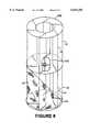
- FIG. 1is a front elevational, partially cut-away, elevational view of one embodiment of wind turbine apparatus of the invention
- FIG. 2is a top view of one embodiment of a rotor which is useful in the apparatus of this invention
- FIG. 2Ais a top view illustrating one of the blades on a preferred rotor for use in this invention
- FIG. 3is a sectional view of the rotor shown in FIG. 2 taken along line 3--3;
- FIG. 4is a top view of one embodiment of a wind turbine apparatus of the invention.
- FIG. 4Ais a cross-sectional view of a preferred airfoil design
- FIG. 5is a top view of another embodiment of rotor which is useful in this invention.
- FIG. 6is an elevational view of a control system useful in this invention.
- FIG. 7is a wiring diagram which is useful in controlling the electrical energy output from a wind turbine apparatus of the invention.
- FIG. 8is a perspective view illustrating another embodiment of wind turbine apparatus of this invention.
- wind turbine apparatus 10 of the inventionwhich comprises a rotatable rotor 12 and a plurality of stationary or fixed airfoils 14 which are positioned around the perimeter of the rotor 12.
- a top plate 10Bis secured to the upper ends of the airfoils
- a bottom plate 10Ais secured to the lower ends of the airfoils to improve structural strength and to force wind currents which enter the apparatus to push against the rotor blades.
- the rotorincludes a plurality of blades 11 which radiate outwardly from a central shaft 13.
- the rotor bladesare preferably all of the same size and style and are equidistantly spaced around the central shaft.
- the preferred shape of the bladesis as shown in FIG. 2.
- the portion 11A along the outer edge of each bladeis angled away from the direction of rotation of the rotor (e.g. about 15 to 80 degrees).
- the bladesare concave on the side which is acted upon by the wind currents.
- the angled outer edge 11Ahelps to hold the moving air current on the blade longer so that more wind energy is captured by the blade.
- each rotor bladeis shown in FIG. 2A.
- the radius of curvature, R.C., of the bladeis such that air is held on the surface of the blade long enough to obtain maximum thrust. Too little curvature (i.e., a flatter blade) does not hold the air on the blade long enough. Too much curvature has a tendency to block a portion of the airflow from the surface and thus lower the efficiency of the turbine.
- the curvature of each rotor bladeis such that an angle of about 65 degrees is defined as illustrated in FIG. 2A.
- each rotor bladeis bent or angled away from the direction of rotation of the rotor central shaft.
- the angle C defined by the outer edge portion 11Ais about 30 degrees.
- the width of edge portion 11Ais in the range of about 2 to 6 inches. If the width of portion 11A is too great, turbulence on the blade is increased and efficiency suffers. If the width is too small, the desired retention effect of holding the air flow on the blade is reduced and efficiency is reduced.
- the preferred shape and arrangement of the airfoilsis as shown in FIGS. 4 and 4A.
- the airfoilsare double convex in cross-section and have a tapered inner edge 14A.
- the outer edge 14Bis rounded.
- Preferably the opposite sides of each airfoilare symmetrically shaped relative to the centerline of the airfoil. This shape provides for much smoother and efficient air flow than is possible with flat, single-curved or double-curved directional blades or stator blades previously proposed by others in this field.
- the preferred cross-sectional shape of the airfoilis as shown in FIG. 4A. Testing pursuant to this invention has shown that there is a direct relationship between the length and the thickness or width of the airfoil to the overall turbine performance.
- a preferred ratio of L to Wis in the range of about 8-12:1 to maintain maximum efficiency of airflow with a minimum of negative turbulence and trailing edge separation.
- a lower ratio of L:Wproduces a more adverse gradient (higher degree of trailing edge separation and increased adverse turbulence).
- Each airfoilis preferably positioned such that the angle B between the airfoil and an adjacent rotor blade is in the range of about 10 to 45 degrees (with 20-30 degrees being preferred), as shown in FIG. 4.
- the design and arrangement of the airfoilsprevent wind currents from impacting the backside of the rotor blades (which would have a tendency to slow the rotor and reduce efficiency). Also, the arrangement of airfoils directs airflow onto each rotor blade from the center of the blade outward in order to maximize the power of the wind.
- the angle A defined between adjacent airfoilsis 60 degrees when six airfoils are used.
- the number of rotor blades relative to the number of airfoilsis very important. It has been found that the ratio of the number of rotor blades to the number of airfoils must be at least 1.25 to 1 (and may be as great as 2:1). When the ratio is less than that just stated, the efficiency of conversion of wind energy to electrical energy is reduced significantly. Preferably there are at least seven rotor blades and at least five airfoils utilized in the apparatus. More preferably there are 8 to 12 rotor blades and 6 to 8 airfoils.
- Rotor rpmwas increased 20 to 25% by using 8 rotor blades and 6 airfoils.
- the number of rotor bladesexceeds a ratio of 2:1, there is resistance to new air inflow at higher wind velocities, thus reducing power applied to the rotor.
- the wind turbine apparatus of the inventioncan be made in any desired size.
- the apparatusmay have a diameter from about 1.5 feet to 48 feet or even greater, if desired.
- the heightmay also vary, for example, from about 1 foot to 30 feet, or more if desired. It is also possible to stack one such apparatus on top of another (e.g. as shown in FIG. 8 where the central shafts of the two units are connected together). It is also possible to offset the airfoils on the upper unit from the airfoils of the lower unit to obtain more uniform application of torque from the two rotors to the central shaft.
- Another feature of this inventionis the provision of wire mesh 18 or screen around the entire periphery of the airfoil assembly. This is also illustrated in FIG. 8.
- the meshprevents birds and persons from intentionally or inadvertently entering into the apparatus where they could be injured by the rotating rotor or where the rotors themselves could become damaged.
- the meshalso prevents trash and debris from entering into the apparatus.
- FIG. 1A preferred form of the wind turbine apparatus for generating electrical energy from wind energy is shown in FIG. 1.
- the central shaft 13 of the rotorextends through the base 10A and into the housing or enclosure 16 on which the apparatus is supported.
- the enclosure 16has four side walls which are angled or sloped inwardly from a floor up to the horizontal roof. The sloped walls facilitate movement of wind currents upwardly toward the rotor.
- the angle of each side wall relative to the flooris in the range of about 20 to 80 degrees (with 45 to 60 degrees being preferred), depending upon installation location and conditions.
- the lower end of the central shaftis connected to a gear box 22 via a flexible omega coupler.
- a disk brake 15is preferably included for the purpose of enabling the central shaft to be slowed and locked in a stationary position whenever repairs or servicing of the apparatus is desired.
- Control units 23control the interconnection of the turbine to the utility grid, for example, or to a battery system for storage of electrical energy.
- the control systemalso provides system performance measurements for operator evaluation, and it also provides for safe shutdown under normal and default conditions.
- the inputs to the control systemare: shaft rpm, generator speed, generator current, generator temperature, vibration, line voltage, wind speed, line harmonics, all fault conditions, over voltage, and utility line surges.
- the control systems shown in FIGS. 6 and 7are commercially available and are described in U.S. Pat. Nos. 5,079,494 and 5,256,949, incorporated herein by reference.
- the wind turbine apparatus of this inventionis useful in a variety of industries and applications, such as transmitter sites, buildings (e.g. office buildings, or recreational cabins, or homes), remote villages, oil platforms, ranches and farms, aircraft (e.g. to provide emergency power for hydraulic systems and control surfaces), recreational vehicles, commercial trucking, shipping, yachts, etc.
- buildingse.g. office buildings, or recreational cabins, or homes
- remote villagesoil platforms
- ranches and farmse.g. to provide emergency power for hydraulic systems and control surfaces
- recreational vehiclescommercial trucking, shipping, yachts, etc.
- the apparatus of this inventionis fully functional for generating electrical energy even in very high wind conditions. Yet, the apparatus is capable of generating electrical energy even at low wind speeds (e.g. 8 miles per hour).
- the apparatusis normally provided as a vertical-axis unit, although it is also possible for the apparatus to be used as a horizontal-axis unit, if desired. For example, in sub-terranean or water (hydro) applications it may be preferred to use a horizontal-axis unit.
- the rotormay be reinforced with a number of gussets 17 which extend horizontally between adjacent rotor blades.
- Preferred gussetsinclude openings 17A as shown in FIG. 5.
- the gussetsalso provide lift to the rotor as wind currents are directed upwardly to the rotor by the sloped walls of the enclosure shown in FIG. 1.
- the gussetsare vertically spaced from each other about 3 to 4 feet apart.
- the gussets as shown hereinhave been proven to be extremely significant in maintaining structural integrity of the rotor at high wind velocities. Rotors which do not include the gussets may not be structurally adequate for use in winds of 60 to 90 miles per hour.
Landscapes
- Engineering & Computer Science (AREA)
- Life Sciences & Earth Sciences (AREA)
- Sustainable Development (AREA)
- Sustainable Energy (AREA)
- Chemical & Material Sciences (AREA)
- Combustion & Propulsion (AREA)
- Mechanical Engineering (AREA)
- General Engineering & Computer Science (AREA)
- Physics & Mathematics (AREA)
- Fluid Mechanics (AREA)
- Power Engineering (AREA)
- Wind Motors (AREA)
Abstract
Description
Claims (16)
Priority Applications (8)
| Application Number | Priority Date | Filing Date | Title |
|---|---|---|---|
| US09/061,508US6015258A (en) | 1998-04-17 | 1998-04-17 | Wind turbine |
| ZA989472AZA989472B (en) | 1998-04-17 | 1998-10-16 | Wind turbine apparatus |
| DE69926240TDE69926240D1 (en) | 1998-04-17 | 1999-04-12 | WIND TURBINE |
| PCT/US1999/007894WO1999054623A1 (en) | 1998-04-17 | 1999-04-12 | Wind turbine |
| EP99916607AEP1095216B1 (en) | 1998-04-17 | 1999-04-12 | Wind turbine |
| AT99916607TATE299994T1 (en) | 1998-04-17 | 1999-04-12 | WIND TURBINE |
| TW088106095ATW514699B (en) | 1998-04-17 | 1999-04-16 | Wind turbine apparatus |
| AU23815/99AAU749851B2 (en) | 1998-04-17 | 1999-04-16 | Wind turbine |
Applications Claiming Priority (1)
| Application Number | Priority Date | Filing Date | Title |
|---|---|---|---|
| US09/061,508US6015258A (en) | 1998-04-17 | 1998-04-17 | Wind turbine |
Publications (1)
| Publication Number | Publication Date |
|---|---|
| US6015258Atrue US6015258A (en) | 2000-01-18 |
Family
ID=22036238
Family Applications (1)
| Application Number | Title | Priority Date | Filing Date |
|---|---|---|---|
| US09/061,508Expired - LifetimeUS6015258A (en) | 1998-04-17 | 1998-04-17 | Wind turbine |
Country Status (8)
| Country | Link |
|---|---|
| US (1) | US6015258A (en) |
| EP (1) | EP1095216B1 (en) |
| AT (1) | ATE299994T1 (en) |
| AU (1) | AU749851B2 (en) |
| DE (1) | DE69926240D1 (en) |
| TW (1) | TW514699B (en) |
| WO (1) | WO1999054623A1 (en) |
| ZA (1) | ZA989472B (en) |
Cited By (48)
| Publication number | Priority date | Publication date | Assignee | Title |
|---|---|---|---|---|
| US6604706B1 (en) | 1998-08-27 | 2003-08-12 | Nicolae Bostan | Gyrostabilized self propelled aircraft |
| US20030209911A1 (en)* | 2002-05-08 | 2003-11-13 | Pechler Elcho R. | Vertical-axis wind turbine |
| US20040036297A1 (en)* | 2002-08-21 | 2004-02-26 | Rowe John | Vertical axis wind turbine |
| US20040061337A1 (en)* | 2002-07-31 | 2004-04-01 | Becker William S. | Wind turbine device |
| US20040120820A1 (en)* | 2002-01-24 | 2004-06-24 | Jacquelin Dery | Vertical axis windmill and self-erecting structure therefor |
| US20040130161A1 (en)* | 2003-01-02 | 2004-07-08 | Gomez Gomar Josep Lluis | Introduced in wind power recovery devices |
| US20040219019A1 (en)* | 2003-04-30 | 2004-11-04 | Taylor Ronald J. | Wind turbine having airfoils for blocking and directing wind and rotors with or without a central gap |
| WO2005010353A3 (en)* | 2003-07-25 | 2005-03-24 | Dixi Holding B V | Improved vertical axis water turbine |
| US20050103148A1 (en)* | 2003-11-17 | 2005-05-19 | Fanuc Ltd | Cable distribution and support equipment for sensor in robot system |
| US20050248160A1 (en)* | 2004-05-05 | 2005-11-10 | Global Wind Technology, Inc. | Omni-directional wind turbine electric generation system |
| US7008171B1 (en) | 2004-03-17 | 2006-03-07 | Circle Wind Corp. | Modified Savonius rotor |
| US20060110243A1 (en)* | 2003-04-30 | 2006-05-25 | Taylor Scott J | Cross-flow wind turbine |
| US20060110251A1 (en)* | 2004-11-24 | 2006-05-25 | Stanley Jonsson | Wind turbine |
| US20060231675A1 (en)* | 2005-03-17 | 2006-10-19 | Nicolae Bostan | Gyro-stabilized air vehicle |
| FR2886353A1 (en)* | 2005-05-27 | 2006-12-01 | Michel Georges Ponge | Wind energy transforming device for e.g. firm, has stator with air inlets delimited by walls channeling air to rotor having vertical vanes, where inlets and vanes are fixed at top and bottom to plates and reinforced by horizontal tympanums |
| US20070222224A1 (en)* | 2006-03-27 | 2007-09-27 | Jonsson Stanley C | Louvered horizontal wind turbine |
| US20070258806A1 (en)* | 2006-05-05 | 2007-11-08 | Hart James R | Helical taper induced vortical flow turbine |
| US20070267874A1 (en)* | 2003-04-30 | 2007-11-22 | Ronald Taylor | Integrated power plant that utilizes renewable and alternative energy sources |
| US20070296218A1 (en)* | 2006-06-27 | 2007-12-27 | Jonsson Stanley C | Wind turbine having variable pitch airfoils |
| US20070296219A1 (en)* | 2005-02-28 | 2007-12-27 | Horia Nica | Boundary Layer Wind Turbine |
| US20070297902A1 (en)* | 2006-06-27 | 2007-12-27 | Jonsson Stanley C | Wind turbine having variable pitch airfoils that close when moving against the direction of the wind |
| US20080008575A1 (en)* | 2006-05-30 | 2008-01-10 | El-Sayed Mohamed E | Vertical axis wind system |
| CN100366894C (en)* | 2002-12-30 | 2008-02-06 | 约瑟普;路易斯;戈麦斯;高马 | Wind power recovery device |
| US20080143117A1 (en)* | 2006-12-18 | 2008-06-19 | Weiqing Shen | High efficiency wind turbine system |
| US20080258468A1 (en)* | 2007-04-17 | 2008-10-23 | Fuller Adam A | Modular Wind-Driven Electrical Power Generator and Method of Manufacture |
| US20090015017A1 (en)* | 2007-07-10 | 2009-01-15 | Cleveland State University | Wind powered electricity generating system |
| US20090184521A1 (en)* | 2008-01-17 | 2009-07-23 | Chong Wun C | Twin wind turbine power system |
| US7605491B1 (en)* | 2008-05-22 | 2009-10-20 | Chun-Neng Chung | Apparatus for generating electric power using wind energy |
| US20090269209A1 (en)* | 2008-04-29 | 2009-10-29 | Urban Roy H | Wind Turbine |
| US20090274561A1 (en)* | 2006-12-14 | 2009-11-05 | Marcelo Ricardo Gornatti | Wind collector device for generation of energy |
| US20100045039A1 (en)* | 2008-08-25 | 2010-02-25 | Mark R. Stroup | Vertical axis wind turbine |
| US20100098542A1 (en)* | 2008-10-20 | 2010-04-22 | Jonsson Stanley C | Wind Turbine Having Two Sets of Air Panels to Capture Wind Moving in Perpendicular Direction |
| US20100158697A1 (en)* | 2008-12-19 | 2010-06-24 | Higher Dimension Materials, Inc. | Multi-rotor vertical axis wind turbine |
| US20100266407A1 (en)* | 2009-04-20 | 2010-10-21 | Barber Gerald L | Wind Turbine with Sail Extensions |
| US20100266412A1 (en)* | 2009-04-20 | 2010-10-21 | Barber Gerald L | Wind Turbine |
| US20100308597A1 (en)* | 2007-10-30 | 2010-12-09 | Viktor Gyorgyi | Wind turbine with vertical axis and wind power plant |
| US20110033291A1 (en)* | 2009-08-04 | 2011-02-10 | Abundant Energy, LLC | Energy transfer system |
| CN101566124B (en)* | 2008-04-21 | 2011-10-05 | 钟俊能 | Power generation device capable of multi-directional wind collection |
| US8358030B2 (en) | 2011-03-17 | 2013-01-22 | Via Verde Limited | Wind turbine apparatus |
| WO2013080192A1 (en) | 2012-01-13 | 2013-06-06 | Pellegri Adriano | Cyclonic vertical axis wind turbine with a wind guide |
| US8546970B2 (en) | 2010-04-20 | 2013-10-01 | 1444555 Alberta Ltd. | Turbine for a fluid stream |
| US20150167635A1 (en)* | 2013-12-17 | 2015-06-18 | Sung Jin Aero Co., Ltd. | Wind power generation unit and wind power generation system of vertically stacked type |
| WO2016030821A1 (en) | 2014-08-29 | 2016-03-03 | RUBIO, Ana Elisa | Three-vane double rotor for vertical axis turbine |
| WO2018073729A1 (en) | 2016-10-18 | 2018-04-26 | Pellegri Adriano | Cyclonic-flow wind turbine with statoric and rotoric elements |
| US20180135599A1 (en)* | 2016-08-14 | 2018-05-17 | Cbc, Llc | Wind turbine |
| EP3748153A4 (en)* | 2018-02-01 | 2021-10-27 | Fierros Farell, Luis Javier | WIND-BASED ELECTRICITY GENERATION SYSTEM |
| US11204016B1 (en)* | 2018-10-24 | 2021-12-21 | Magnelan Energy LLC | Light weight mast for supporting a wind turbine |
| US11655798B2 (en) | 2021-08-26 | 2023-05-23 | Daniel Maurice Lerner | Multistage vertical axis wind turbine |
Families Citing this family (5)
| Publication number | Priority date | Publication date | Assignee | Title |
|---|---|---|---|---|
| WO2011017780A2 (en)* | 2009-08-12 | 2011-02-17 | Josip Bilic | Vertical wind turbine with two rotors (vwt-2126) |
| WO2011160688A1 (en)* | 2010-06-23 | 2011-12-29 | Lightyears Holding Ag | Wind turbine |
| ITAV20100008A1 (en)* | 2010-12-14 | 2011-03-15 | Mario Montagna | UNIVERSAL WIND GENERATOR |
| WO2013020595A2 (en) | 2011-08-10 | 2013-02-14 | Lightyears Holding Ag | Windpower machine |
| RU184213U1 (en)* | 2018-04-18 | 2018-10-18 | Федеральное государственное автономное образовательное учреждение высшего образования "Дальневосточный федеральный университет" (ДВФУ) | Wind power plant |
Citations (9)
| Publication number | Priority date | Publication date | Assignee | Title |
|---|---|---|---|---|
| US3938907A (en)* | 1974-06-24 | 1976-02-17 | Windsunwatt, Inc. | Horizontal multidirectional turbine windmill |
| US4236866A (en)* | 1976-12-13 | 1980-12-02 | Valentin Zapata Martinez | System for the obtainment and the regulation of energy starting from air, sea and river currents |
| US4365929A (en)* | 1981-01-16 | 1982-12-28 | Philip Retz | Vertical wind turbine power generating tower |
| US4575311A (en)* | 1981-12-21 | 1986-03-11 | Indal Technologies Inc. | Gear box assembly-upper head assembly |
| US5133637A (en)* | 1991-03-22 | 1992-07-28 | Wadsworth William H | Vertical axis wind turbine generator |
| US5380149A (en)* | 1990-05-31 | 1995-01-10 | Valsamidis; Michael | Wind turbine cross wind machine |
| US5391926A (en)* | 1992-08-18 | 1995-02-21 | Staley; Frederick J. | Wind turbine particularly suited for high-wind conditions |
| US5463257A (en)* | 1993-11-23 | 1995-10-31 | Yea; Ton A. | Wind power machine |
| US5553996A (en)* | 1993-02-10 | 1996-09-10 | Farrar; Austin P. | Wind powered turbine |
Family Cites Families (2)
| Publication number | Priority date | Publication date | Assignee | Title |
|---|---|---|---|---|
| US4269563A (en)* | 1979-08-09 | 1981-05-26 | Errol W. Sharak | Wind turbine |
| US5664418A (en)* | 1993-11-24 | 1997-09-09 | Walters; Victor | Whirl-wind vertical axis wind and water turbine |
- 1998
- 1998-04-17USUS09/061,508patent/US6015258A/ennot_activeExpired - Lifetime
- 1998-10-16ZAZA989472Apatent/ZA989472B/enunknown
- 1999
- 1999-04-12ATAT99916607Tpatent/ATE299994T1/ennot_activeIP Right Cessation
- 1999-04-12DEDE69926240Tpatent/DE69926240D1/ennot_activeExpired - Lifetime
- 1999-04-12EPEP99916607Apatent/EP1095216B1/ennot_activeExpired - Lifetime
- 1999-04-12WOPCT/US1999/007894patent/WO1999054623A1/enactiveIP Right Grant
- 1999-04-16TWTW088106095Apatent/TW514699B/ennot_activeIP Right Cessation
- 1999-04-16AUAU23815/99Apatent/AU749851B2/ennot_activeCeased
Patent Citations (9)
| Publication number | Priority date | Publication date | Assignee | Title |
|---|---|---|---|---|
| US3938907A (en)* | 1974-06-24 | 1976-02-17 | Windsunwatt, Inc. | Horizontal multidirectional turbine windmill |
| US4236866A (en)* | 1976-12-13 | 1980-12-02 | Valentin Zapata Martinez | System for the obtainment and the regulation of energy starting from air, sea and river currents |
| US4365929A (en)* | 1981-01-16 | 1982-12-28 | Philip Retz | Vertical wind turbine power generating tower |
| US4575311A (en)* | 1981-12-21 | 1986-03-11 | Indal Technologies Inc. | Gear box assembly-upper head assembly |
| US5380149A (en)* | 1990-05-31 | 1995-01-10 | Valsamidis; Michael | Wind turbine cross wind machine |
| US5133637A (en)* | 1991-03-22 | 1992-07-28 | Wadsworth William H | Vertical axis wind turbine generator |
| US5391926A (en)* | 1992-08-18 | 1995-02-21 | Staley; Frederick J. | Wind turbine particularly suited for high-wind conditions |
| US5553996A (en)* | 1993-02-10 | 1996-09-10 | Farrar; Austin P. | Wind powered turbine |
| US5463257A (en)* | 1993-11-23 | 1995-10-31 | Yea; Ton A. | Wind power machine |
Cited By (82)
| Publication number | Priority date | Publication date | Assignee | Title |
|---|---|---|---|---|
| US6604706B1 (en) | 1998-08-27 | 2003-08-12 | Nicolae Bostan | Gyrostabilized self propelled aircraft |
| US7044422B2 (en) | 1998-08-27 | 2006-05-16 | Nicolae Bostan | Gyrostabilized self propelled aircraft |
| US6979170B2 (en) | 2002-01-24 | 2005-12-27 | Dermond Inc. | Vertical axis windmill and self-erecting structure therefor |
| US20040120820A1 (en)* | 2002-01-24 | 2004-06-24 | Jacquelin Dery | Vertical axis windmill and self-erecting structure therefor |
| US6870280B2 (en)* | 2002-05-08 | 2005-03-22 | Elcho R. Pechler | Vertical-axis wind turbine |
| US20030209911A1 (en)* | 2002-05-08 | 2003-11-13 | Pechler Elcho R. | Vertical-axis wind turbine |
| US7132760B2 (en)* | 2002-07-31 | 2006-11-07 | Becker William S | Wind turbine device |
| US20040061337A1 (en)* | 2002-07-31 | 2004-04-01 | Becker William S. | Wind turbine device |
| US20040036297A1 (en)* | 2002-08-21 | 2004-02-26 | Rowe John | Vertical axis wind turbine |
| US6740989B2 (en) | 2002-08-21 | 2004-05-25 | Pacifex Management Inc. | Vertical axis wind turbine |
| CN100366894C (en)* | 2002-12-30 | 2008-02-06 | 约瑟普;路易斯;戈麦斯;高马 | Wind power recovery device |
| US20040130161A1 (en)* | 2003-01-02 | 2004-07-08 | Gomez Gomar Josep Lluis | Introduced in wind power recovery devices |
| US6841894B2 (en)* | 2003-01-02 | 2005-01-11 | Josep Lluis Gomez Gomar | Wind power generator having wind channeling body with progressively reduced section |
| US7759812B2 (en) | 2003-04-30 | 2010-07-20 | Terra Moya Aqua, Inc. | Integrated power plant that utilizes renewable and alternative energy sources |
| US20040219019A1 (en)* | 2003-04-30 | 2004-11-04 | Taylor Ronald J. | Wind turbine having airfoils for blocking and directing wind and rotors with or without a central gap |
| US6966747B2 (en) | 2003-04-30 | 2005-11-22 | Taylor Ronald J | Wind turbine having airfoils for blocking and directing wind and rotors with or without a central gap |
| US7347660B2 (en) | 2003-04-30 | 2008-03-25 | Terra Moya Aqua, Inc. | Cross-flow wind turbine |
| WO2004099605A2 (en) | 2003-04-30 | 2004-11-18 | Taylor Ronald J | Wind turbine having airfoils for blocking and directing wind and rotors with or without a central gap |
| US20060110243A1 (en)* | 2003-04-30 | 2006-05-25 | Taylor Scott J | Cross-flow wind turbine |
| US20070267874A1 (en)* | 2003-04-30 | 2007-11-22 | Ronald Taylor | Integrated power plant that utilizes renewable and alternative energy sources |
| US20070154299A1 (en)* | 2003-04-30 | 2007-07-05 | Terra Moya Aqua, Inc. | Cross-flow wind turbine |
| US7189050B2 (en) | 2003-04-30 | 2007-03-13 | Terra Moya Aqua, Inc. | Cross-flow wind turbine |
| WO2005010353A3 (en)* | 2003-07-25 | 2005-03-24 | Dixi Holding B V | Improved vertical axis water turbine |
| US20050103148A1 (en)* | 2003-11-17 | 2005-05-19 | Fanuc Ltd | Cable distribution and support equipment for sensor in robot system |
| US7008171B1 (en) | 2004-03-17 | 2006-03-07 | Circle Wind Corp. | Modified Savonius rotor |
| WO2005108785A3 (en)* | 2004-05-05 | 2006-03-09 | Global Wind Technology Inc | Omni-directional wind turbine electric generation system |
| US20050248160A1 (en)* | 2004-05-05 | 2005-11-10 | Global Wind Technology, Inc. | Omni-directional wind turbine electric generation system |
| US7109599B2 (en)* | 2004-05-05 | 2006-09-19 | Watkins Philip G | Omni-directional wind turbine electric generation system |
| US20060110251A1 (en)* | 2004-11-24 | 2006-05-25 | Stanley Jonsson | Wind turbine |
| US7182573B2 (en) | 2004-11-24 | 2007-02-27 | Stanley Jonsson | Wind turbine |
| US7573148B2 (en) | 2005-02-28 | 2009-08-11 | Horia Nica | Boundary layer wind turbine |
| US20070296219A1 (en)* | 2005-02-28 | 2007-12-27 | Horia Nica | Boundary Layer Wind Turbine |
| US20100012790A1 (en)* | 2005-03-17 | 2010-01-21 | Nicolae Bostan | Gyro-stabilized air vehicle |
| US20060231675A1 (en)* | 2005-03-17 | 2006-10-19 | Nicolae Bostan | Gyro-stabilized air vehicle |
| US7520466B2 (en) | 2005-03-17 | 2009-04-21 | Nicolae Bostan | Gyro-stabilized air vehicle |
| FR2886353A1 (en)* | 2005-05-27 | 2006-12-01 | Michel Georges Ponge | Wind energy transforming device for e.g. firm, has stator with air inlets delimited by walls channeling air to rotor having vertical vanes, where inlets and vanes are fixed at top and bottom to plates and reinforced by horizontal tympanums |
| US7323791B2 (en) | 2006-03-27 | 2008-01-29 | Jonsson Stanley C | Louvered horizontal wind turbine |
| US20070222224A1 (en)* | 2006-03-27 | 2007-09-27 | Jonsson Stanley C | Louvered horizontal wind turbine |
| US20070258806A1 (en)* | 2006-05-05 | 2007-11-08 | Hart James R | Helical taper induced vortical flow turbine |
| US7494315B2 (en) | 2006-05-05 | 2009-02-24 | Hart James R | Helical taper induced vortical flow turbine |
| US20100007144A1 (en)* | 2006-05-30 | 2010-01-14 | Analytical Design Service Corporation | Vertical axis wind system |
| US20080008575A1 (en)* | 2006-05-30 | 2008-01-10 | El-Sayed Mohamed E | Vertical axis wind system |
| US7948111B2 (en) | 2006-05-30 | 2011-05-24 | Analytical Design Service Corporation | Vertical axis wind system |
| US7550865B2 (en) | 2006-06-27 | 2009-06-23 | Jonsson Stanley C | Wind turbine having variable pitch airfoils that close when moving against the direction of the wind |
| US7385302B2 (en) | 2006-06-27 | 2008-06-10 | Jonsson Stanley C | Wind turbine having variable pitch airfoils |
| US20070297902A1 (en)* | 2006-06-27 | 2007-12-27 | Jonsson Stanley C | Wind turbine having variable pitch airfoils that close when moving against the direction of the wind |
| US20070296218A1 (en)* | 2006-06-27 | 2007-12-27 | Jonsson Stanley C | Wind turbine having variable pitch airfoils |
| US8240977B2 (en)* | 2006-12-14 | 2012-08-14 | Marcelo Ricardo Gornatti | Wind collector device for generation of energy |
| US20090274561A1 (en)* | 2006-12-14 | 2009-11-05 | Marcelo Ricardo Gornatti | Wind collector device for generation of energy |
| US20080143117A1 (en)* | 2006-12-18 | 2008-06-19 | Weiqing Shen | High efficiency wind turbine system |
| US20080258468A1 (en)* | 2007-04-17 | 2008-10-23 | Fuller Adam A | Modular Wind-Driven Electrical Power Generator and Method of Manufacture |
| US8322992B2 (en) | 2007-04-17 | 2012-12-04 | Adam Fuller | Modular wind-driven electrical power generator and method of manufacture |
| US20090015017A1 (en)* | 2007-07-10 | 2009-01-15 | Cleveland State University | Wind powered electricity generating system |
| US7679209B2 (en) | 2007-07-10 | 2010-03-16 | Cleveland State University | Wind powered electricity generating system |
| US8400008B2 (en)* | 2007-10-30 | 2013-03-19 | Viktor Gyorgyi | Wind turbine with vertical axis and wind power plant |
| US20100308597A1 (en)* | 2007-10-30 | 2010-12-09 | Viktor Gyorgyi | Wind turbine with vertical axis and wind power plant |
| US20090184521A1 (en)* | 2008-01-17 | 2009-07-23 | Chong Wun C | Twin wind turbine power system |
| US8057159B2 (en) | 2008-01-17 | 2011-11-15 | Chong Wun C | Twin wind turbine power system |
| CN101566124B (en)* | 2008-04-21 | 2011-10-05 | 钟俊能 | Power generation device capable of multi-directional wind collection |
| US8070449B2 (en) | 2008-04-29 | 2011-12-06 | Absolute Turn, Inc. | Wind turbine |
| US20090269209A1 (en)* | 2008-04-29 | 2009-10-29 | Urban Roy H | Wind Turbine |
| US7605491B1 (en)* | 2008-05-22 | 2009-10-20 | Chun-Neng Chung | Apparatus for generating electric power using wind energy |
| US8232664B2 (en) | 2008-08-25 | 2012-07-31 | Mark R. Stroup | Vertical axis wind turbine |
| US20100045039A1 (en)* | 2008-08-25 | 2010-02-25 | Mark R. Stroup | Vertical axis wind turbine |
| US20100098542A1 (en)* | 2008-10-20 | 2010-04-22 | Jonsson Stanley C | Wind Turbine Having Two Sets of Air Panels to Capture Wind Moving in Perpendicular Direction |
| US20100158697A1 (en)* | 2008-12-19 | 2010-06-24 | Higher Dimension Materials, Inc. | Multi-rotor vertical axis wind turbine |
| US8109727B2 (en) | 2009-04-20 | 2012-02-07 | Barber Gerald L | Wind turbine |
| US8258645B2 (en) | 2009-04-20 | 2012-09-04 | Barber Gerald L | Wind turbine with sail extensions |
| US20100266412A1 (en)* | 2009-04-20 | 2010-10-21 | Barber Gerald L | Wind Turbine |
| US20100266407A1 (en)* | 2009-04-20 | 2010-10-21 | Barber Gerald L | Wind Turbine with Sail Extensions |
| US20110033291A1 (en)* | 2009-08-04 | 2011-02-10 | Abundant Energy, LLC | Energy transfer system |
| US8546970B2 (en) | 2010-04-20 | 2013-10-01 | 1444555 Alberta Ltd. | Turbine for a fluid stream |
| US8358030B2 (en) | 2011-03-17 | 2013-01-22 | Via Verde Limited | Wind turbine apparatus |
| WO2013080192A1 (en) | 2012-01-13 | 2013-06-06 | Pellegri Adriano | Cyclonic vertical axis wind turbine with a wind guide |
| US20150167635A1 (en)* | 2013-12-17 | 2015-06-18 | Sung Jin Aero Co., Ltd. | Wind power generation unit and wind power generation system of vertically stacked type |
| WO2016030821A1 (en) | 2014-08-29 | 2016-03-03 | RUBIO, Ana Elisa | Three-vane double rotor for vertical axis turbine |
| US20180135599A1 (en)* | 2016-08-14 | 2018-05-17 | Cbc, Llc | Wind turbine |
| US10495063B2 (en)* | 2016-08-14 | 2019-12-03 | Cbc, Llc | Wind turbine |
| WO2018073729A1 (en) | 2016-10-18 | 2018-04-26 | Pellegri Adriano | Cyclonic-flow wind turbine with statoric and rotoric elements |
| EP3748153A4 (en)* | 2018-02-01 | 2021-10-27 | Fierros Farell, Luis Javier | WIND-BASED ELECTRICITY GENERATION SYSTEM |
| US11204016B1 (en)* | 2018-10-24 | 2021-12-21 | Magnelan Energy LLC | Light weight mast for supporting a wind turbine |
| US11655798B2 (en) | 2021-08-26 | 2023-05-23 | Daniel Maurice Lerner | Multistage vertical axis wind turbine |
Also Published As
| Publication number | Publication date |
|---|---|
| EP1095216A1 (en) | 2001-05-02 |
| ATE299994T1 (en) | 2005-08-15 |
| ZA989472B (en) | 1999-04-21 |
| WO1999054623A1 (en) | 1999-10-28 |
| TW514699B (en) | 2002-12-21 |
| AU749851B2 (en) | 2002-07-04 |
| DE69926240D1 (en) | 2005-08-25 |
| EP1095216B1 (en) | 2005-07-20 |
| AU2381599A (en) | 1999-10-28 |
Similar Documents
| Publication | Publication Date | Title |
|---|---|---|
| US6015258A (en) | Wind turbine | |
| US7084523B2 (en) | Windmill for wind power generation | |
| US4350900A (en) | Wind energy machine | |
| US6857846B2 (en) | Stackable vertical axis windmill | |
| US6710469B2 (en) | Fluid-powered energy conversion device | |
| US6800955B2 (en) | Fluid-powered energy conversion device | |
| US6191496B1 (en) | Wind turbine system | |
| AU2008267780B2 (en) | A wind turbine having an airflow deflector | |
| US20010004439A1 (en) | Energy converter | |
| US20090110554A1 (en) | Wind Turbine for Generating Electricity | |
| US20060113804A1 (en) | Passively cooled direct drive wind turbine | |
| WO1992004542A1 (en) | Vertical axis wind powered generator | |
| KR101849052B1 (en) | Ventilator using wind power induced by direction key and non-powered fan driving system | |
| EP2012007B1 (en) | Vertical axis wind turbine | |
| JP7579387B2 (en) | Wind power plant | |
| JPH11294313A (en) | Hybrid windmill type power generation system | |
| WO2008088921A2 (en) | Vertical windmills and methods of operating the same | |
| KR20090051669A (en) | Wind-generated windmills | |
| US20040184909A1 (en) | Multi-rotor blade stackable vertical axis windmill | |
| CN214998017U (en) | Self-adaptive wind gathering and discharging small wind power generation device | |
| KR101418674B1 (en) | Louver guided wind turbine | |
| JP2003222071A (en) | An invention in which a Darrieus-type wind power generator having a plurality of generators and a wind collecting panel are attached. | |
| US20140175801A1 (en) | Wind turbine power generator | |
| CN101319653B (en) | Self-adapting wind wheel for wind power generation | |
| KR20140123324A (en) | Ventilation Duct Exhaust Energy Capturing Power Generation System |
Legal Events
| Date | Code | Title | Description |
|---|---|---|---|
| STCF | Information on status: patent grant | Free format text:PATENTED CASE | |
| AS | Assignment | Owner name:TERRA AQUA MOYA, INC., WYOMING Free format text:ASSIGNMENT OF ASSIGNORS INTEREST;ASSIGNOR:TAYLOR, RONALD J.;REEL/FRAME:010848/0627 Effective date:20000801 | |
| AS | Assignment | Owner name:TERRA MOYA AQUA, INC., A CORPORATION OF WYOMING, W Free format text:CORRECTIVE ASSIGNMENT TO CORRECT THE ASSIGNEE, PREVIOUSLY RECORDED AT REEL 010848 FRAME 0627;ASSIGNOR:TAYLOR, RONALD J.;REEL/FRAME:011084/0501 Effective date:20000801 | |
| AS | Assignment | Owner name:NORDIC, GARY, COLORADO Free format text:SECURITY INTEREST;ASSIGNORS:RASMUSSEN, DUANE A.;TAYLOR, RONALD J.;REEL/FRAME:011219/0237 Effective date:20000829 Owner name:DEINE, KENNETH, COLORADO Free format text:SECURITY INTEREST;ASSIGNORS:RASMUSSEN, DUANE A.;TAYLOR, RONALD J.;REEL/FRAME:011219/0237 Effective date:20000829 | |
| FEPP | Fee payment procedure | Free format text:PAYOR NUMBER ASSIGNED (ORIGINAL EVENT CODE: ASPN); ENTITY STATUS OF PATENT OWNER: SMALL ENTITY | |
| FPAY | Fee payment | Year of fee payment:4 | |
| FPAY | Fee payment | Year of fee payment:8 | |
| REMI | Maintenance fee reminder mailed | ||
| FPAY | Fee payment | Year of fee payment:12 | |
| SULP | Surcharge for late payment | Year of fee payment:11 |