US6014579A - Endocardial mapping catheter with movable electrode - Google Patents
Endocardial mapping catheter with movable electrodeDownload PDFInfo
- Publication number
- US6014579A US6014579AUS08/897,657US89765797AUS6014579AUS 6014579 AUS6014579 AUS 6014579AUS 89765797 AUS89765797 AUS 89765797AUS 6014579 AUS6014579 AUS 6014579A
- Authority
- US
- United States
- Prior art keywords
- arms
- electrode
- proximal
- catheter
- distal
- Prior art date
- Legal status (The legal status is an assumption and is not a legal conclusion. Google has not performed a legal analysis and makes no representation as to the accuracy of the status listed.)
- Expired - Fee Related
Links
Images


Classifications
- A—HUMAN NECESSITIES
- A61—MEDICAL OR VETERINARY SCIENCE; HYGIENE
- A61B—DIAGNOSIS; SURGERY; IDENTIFICATION
- A61B5/00—Measuring for diagnostic purposes; Identification of persons
- A61B5/68—Arrangements of detecting, measuring or recording means, e.g. sensors, in relation to patient
- A61B5/6846—Arrangements of detecting, measuring or recording means, e.g. sensors, in relation to patient specially adapted to be brought in contact with an internal body part, i.e. invasive
- A61B5/6847—Arrangements of detecting, measuring or recording means, e.g. sensors, in relation to patient specially adapted to be brought in contact with an internal body part, i.e. invasive mounted on an invasive device
- A61B5/6852—Catheters
- A61B5/6858—Catheters with a distal basket, e.g. expandable basket
- A—HUMAN NECESSITIES
- A61—MEDICAL OR VETERINARY SCIENCE; HYGIENE
- A61B—DIAGNOSIS; SURGERY; IDENTIFICATION
- A61B5/00—Measuring for diagnostic purposes; Identification of persons
- A61B5/24—Detecting, measuring or recording bioelectric or biomagnetic signals of the body or parts thereof
- A61B5/25—Bioelectric electrodes therefor
- A61B5/279—Bioelectric electrodes therefor specially adapted for particular uses
- A61B5/28—Bioelectric electrodes therefor specially adapted for particular uses for electrocardiography [ECG]
- A61B5/283—Invasive
- A61B5/287—Holders for multiple electrodes, e.g. electrode catheters for electrophysiological study [EPS]
- A—HUMAN NECESSITIES
- A61—MEDICAL OR VETERINARY SCIENCE; HYGIENE
- A61B—DIAGNOSIS; SURGERY; IDENTIFICATION
- A61B2562/00—Details of sensors; Constructional details of sensor housings or probes; Accessories for sensors
- A61B2562/04—Arrangements of multiple sensors of the same type
- A61B2562/043—Arrangements of multiple sensors of the same type in a linear array
Definitions
- This inventionrelates generally to endocardial mapping catheters and, more particularly, to endocardial mapping catheters with movable electrodes.
- Endocardial mapping cathetershave heretofore been provided. See, for example, U.S. Pat. No. 5,156,151 to Imran. Movable electrodes have been provided for use therewith.
- U.S. Pat. No. 5,400,783 to Pomerariz et al.discloses a plurality of movable electrodes mounted on an arm swingably disposed within a basket assembly.
- U.S. Pat. No. 5,324,284discloses an endocardial mapping system utilizing a separately controlled ablation catheter. See also U.S. Pat. No. 5,476,495 to Kordis et al. It has been found that endocardial mapping catheters having other types of movable electrodes would be desirable.
- Another object of the inventionis to provide an endocardial mapping catheter of the above character in which the movable electrode is an ablation electrode carried within a basket-like assembly and having a diameter which is large relative to the diameter of the catheter shaft on which the ablation electrode is mounted.
- Another object of the inventionis to provide an endocardial mapping catheter of the above character in which the ablation electrode has a diameter which is large relative to the diameter of the lumen in the catheter shaft of the basket-like assembly in which the ablation catheter shaft is disposed.
- Another object of the inventionis to provide an endocardial mapping catheter of the above character in which the movable electrode is a saline electrode.
- Another object of the inventionis to provide an endocardial mapping catheter of the above character in which the movable electrode is slidably disposed on a basket-like assembly.
- Another object of the inventionis to provide an endocardial mapping catheter of the above character in which the movable electrode is slidably disposed on an arm rotatably mounted within the basket-like assembly.
- Another object of the inventionis to provide an endocardial mapping catheter of the above character in which the movable electrode is slidably disposed on a pull wire of a basket-like assembly.
- Another object of the inventionis to provide an endocardial mapping catheter of the above character in which the movable electrode is cantilevered from the pull wire so as to be positionable between the arms of the basket-like assembly.
- Another object of the inventionis to provide an endocardial mapping catheter of the above character in which the movable electrode can be directed in first and second opposite directions by means of a push/pull wire.
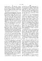
- FIG. 1is a side elevational view, partially cut away, of an embodiment of the endocardial mapping catheter with movable electrode of the present invention.
- FIG. 2is an enlarged side elevational view, partially sectioned, of the catheter of FIG. 1 taken along the line 2--2 of FIG. 1.
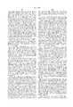
- FIG. 3is a cross-sectional view of the catheter of FIG. 1 taken along the line 3--3 of FIG. 1.
- FIG. 4is a cross-sectional view of the movable electrode of the catheter of FIG. 1 taken along the line 4--4 of FIG. 1.
- FIG. 5is a cross-sectional view of the movable electrode of the catheter of FIG. 1 taken along the line 5--5 of FIG. 4.
- FIG. 6is a cross-sectional view of the catheter of FIG. 1 taken along the line 6--6 of FIG. 1.
- FIG. 7is a cross-sectional view, similar to FIG. 5, of an alternate embodiment of the catheter of FIG. 1.
- FIG. 8is a cross-sectional view, similar to FIG. 4, of another embodiment of the movable electrode of the catheter of FIG. 1.
- FIG. 9is a cross-sectional view, similar to FIG. 4, of a further embodiment of the movable electrode of the catheter of FIG. 1.
- FIG. 10is a cross-sectional view, similar to FIG. 4, of another embodiment of the movable electrode of the catheter of FIG. 1.
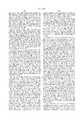
- FIG. 11is a side elevational view, partially cut away, of another embodiment of the endocardial mapping catheter with movable electrode of the present invention.
- FIG. 12is a cross-sectional view of the movable electrode of the catheter of FIG. 11 taken along the line 12--12 of FIG. 11.
- FIG. 13is a cross-sectional view of the movable electrode of the catheter of FIG. 11 taken along the line 13--13 of FIG. 12.
- FIG. 14is a cross-sectional view, similar to FIG. 12, of another embodiment of the endocardial mapping catheter with movable electrode of the present invention.
- FIG. 15is a cross-sectional view of the endocardial mapping catheter of FIG. 14 taken along the line 15--15 of FIG. 14.
- FIG. 16is a cross-sectional view of the endocardial mapping catheter of FIG. 14 taken along the line 16--16 of FIG. 14.
- FIG. 17is a cross-sectional view of a portion of the handle means of the endocardial mapping catheter of FIG. 14.
- FIG. 18is a side elevational view of a further embodiment of the endocardial mapping catheter with movable electrode of the present invention.
- FIG. 19is a cross-sectional view of the movable electrode of the catheter of FIG. 18 taken along the line 19--19 of FIG. 18.
- FIG. 20is a side elevational view of another embodiment of the endocardial mapping catheter with movable electrode of the present invention.
- FIG. 21is a cross-sectional view of the endocardial mapping catheter of FIG. 20 taken along the line 21--21 of FIG. 20.
- an endocardial mapping catheterfor introduction into a chamber of a heart formed by a wall.
- the flexible elongate tubular memberhas proximal and distal extremities and extends along a longitudinal axis.
- a plurality of longitudinally-extending spaced-apart membersare carried by the distal extremity of the flexible elongate tubular member and have proximal and distal extremities.
- Meansis provided for interconnecting the distal extremities of the longitudinally-extending members.
- Certain of the plurality of longitudinally-extending membersare arms of a basket-like assembly and are movable between contracted positions and expanded positions in which the arms bow outwardly from the longitudinal axis.
- a plurality of longitudinally spaced-apart electrodesare carried by each of the arms. Electrical means extends through the flexible elongate tubular member and is connected to the electrodes for performing electrical functions with respect to the electrodes. At least one additional electrode and means for slidably mounting the additional electrode on one of the longitudinally-extending members are provided
- an endocardial mapping catheter 31is shown in FIGS. 1-7 and includes a flexible elongate tubular member or catheter shaft 32 made from any suitable material such as plastic.
- Shaft 32has an external size ranging from 5 to 11 French.
- Catheter shaft 32has proximal and distal extremities 32a and 32b and length so that when the distal extremity is inside a chamber of the heart the proximal extremity is outside of the body.
- the catheter shaft 32extends along a central longitudinal axis 33 and is provided with at least one lumen in the form of central passageway 36 extending between extremities 32a and 32b of the catheter shaft and having an internal diameter of approximately 0.045 inch.
- the catheter shaft 32can have a metal braid (not shown) or other reinforcing member for providing torsional rigidity to the catheter shaft.
- An expandable meansis carried by distal extremity 32b of catheter shaft 32 and is formed from a plurality of longitudinally-extending spaced-apart members (see FIGS. 1 and 2).
- the expandable meansincludes a basket-like assembly or basket assembly 37 having a plurality of eight elongate members or arms 38 with proximal and distal extremities 38a and 38b.
- Basket assembly 37is movable between a first or contracted position shown partially in dashed lines in FIG. 1, in which the basket assembly is adapted to pass through a vessel of the body into a chamber of the heart, and a second or expanded position shown in solid lines in FIG. 1, in which basket arms 38 bow outwardly relative to longitudinal axis 33 so as to engage the inside of the wall of the heart.
- Arms 38are circumferentially spaced-apart about axis 33 at approximately 45° angles so as to be symmetrically positioned.
- Spaces 41are provided between arms 38 for permitting blood to flow through basket assembly 37 while it is in its expanded position in the heart.
- each arm 38is generally strip-like in conformation and has opposite inner and outer generally parallel surfaces 43 (see FIGS. 1 and 2).
- Each arm 38includes a flexible elongate support member or strip 44 made from any suitable material such as Nitinol or another superelastic shape memory alloy and is provided with a predetermined bowed shape.
- a plurality of electrodes 46are carried by basket assembly 37 in longitudinally and radially spaced-apart positions along the arms 38.
- each arm 38has a flex strip 47 with a plurality of eight electrodes 46 in longitudinally spaced-apart positions thereon.
- the eight electrodes on each arm 38are grouped in four pairs so as to provide a plurality of four longitudinally spaced-apart electrode pairs 48 as shown in FIG. 1.
- the flex strip 47 in each arm 38further includes a plurality of electrical or lead means in the form of conductive traces 49 which extend longitudinally along the flex strip. Traeces 49, a portion of one of which is shown in dashed lines in FIG. 1, are electrically connected to electrodes 46.
- An encapsulating PET sleeve 51is heat shrunk around the flex strip 47 and other interior components of arms 38.
- Meansis included within probe 31 for securing proximal extremities 38a of arms 38 in circumferentially spaced-apart positions about distal extremity 32b of catheter shaft 32 (see FIG. 2).
- medical probeis provided with a tubular inner bushing 56 made from a stainless steel hypotube or other suitable material.
- the proximal end of inner bushing 56is press fit within the distal end of passageway 36 and secured within catheter shaft 32 by any suitable means such as an adhesive (not shown).
- Intermediate and outer bushings 57 and 58each made form a stainless steel hypotube or other suitable material, extend concentrically around the distal extremity of inner bushing 56.
- the proximal extremities of flex strips 47extend longitudinally along the outside of outer bushing 58.
- the proximal extremities of support strips 44extend with an interference fit between bushings 56, 57 and 58 so as to secure arm proximal extremities 38a to catheter shaft 32. More specifically, the proximal ends of the support strips 44 from four of the eight arms 38, such arms 38 circumferentially spaced approximately 90° relative to each other, extend between inner and intermediate bushings 56 and 57.
- the proximal ends of the support strips 44 from the other four arms 38, such other arms 38 circumferentially spaced approximately 90° relative to each other,extend between intermediate and outer bushings 57 and 58. In this manner, support strips 44 of adjacent arms 38 alternate around the catheter shaft from extending between bushings 56 and 57 and bushings 57 and 58.
- Flex strips 47 with traces 49 thereonextend longitudinally in a proximal direction from arm proximal extremities 38a as shown in FIG. 2.
- Lead or electrical means in the form of eight cables 66extend through additional lumen 67 of catheter shaft 32.
- Each cable 66includes a plurality of at least eight conductive filaments or conductors (not shown). The distal ends of cables 66 are respectively secured to the proximal ends of flex strips 47 and the conductive fibers of the cables are connected to traces 49 on the flex strips 47.
- An encapsulant made from any suitable material such as epoxyextends through and circumferentially around inner bushing 56 on both sides of the proximal ends of flex strips 47 and the distal ends of cables 66 for providing a flexible body 68 which extends distally of catheter shaft 32 to proximal extremities 38a of arms 38.
- Arms 38extend distally of catheter shaft 32 so that adjacent arms 38 extend at an acute angle relative to each other when basket assembly 37 is in an expanded position as shown in solid lines in FIG. 1. Arm distal extremities 38b are joined together as shown in FIGS. 1 and 3 so that adjacent distal extremities 38b meet at an acute angle relative to each other.
- tip 71serves as the means of medical probe 31 for interconnecting the distal extremities 38b of arms 38.
- a disk 72 formed from first and second plate members 73 and 74is disposed at a substantially right angle to central longitudinal axis 33 for securing together arm distal extremities 38b.
- Disk 72is provided with a plurality of slots (not shown) extending through the top and bottom surfaces 76 and 77 thereof for receiving distal stubs 78 of support strips 44.
- An enlarged tig weld 81is provided on the end of each distal stub 78 for retaining the arm distal extremity 38b within the slot of disk 72.
- Disk 72is encapsulated within any suitable elastomeric and soft material such as silicone 82 for providing tip 71 with a soft, rounded distal end 83.
- Meansis included within basket assembly 37 for inhibiting the formation of thrombus thereon when the basket assembly is disposed in the chamber of the heart.
- webbingsmade from any suitable elastomeric and durable material such as tecoflex polyurethane is provided between the vees formed by adjacent proximal extremities 38a and the vees formed by adjacent distal extremities 38b of arms 38.
- the basket assembly 37is coated with a suitable anti-thrombogenic agent as for example heparin, hirudin and streptokinase containing coatings (not shown) prior to insertion of probe 31 into the body.
- a handle meansis coupled to proximal extremity 32a of catheter shaft 32 and includes a three-fold fitment 91 secured to the proximal extremity 32a for moving catheter shaft 32 and basket assembly 37 longitudinally through a lumen of a body into the heart (see FIG. 1).
- Fitment 91is provided with a central or in line fitting 91a and left and right fittings 91b and 91c disposed on either side of central fitting 91a.
- Left fitting 91bis in communication with additional lumen 67 so as to permit cables 66 to extend from catheter shaft 32.
- a connector 92is attached to the proximal end of cables 66 and is provided with a plurality of pins (not shown) electrically coupled to the conductors of cables 66 for permitting electrical functions to be performed with respect to electrodes 46 carried by basket assembly 37.
- a conventional flexible strain relief 93made from any suitable material such as polyolefin is concentrically mounted over the distal end of fitment 91 and the proximal end of catheter shaft 32 for providing a transition in stiffness between the catheter shaft 32 and fitment 91.
- the expandable means carried by distal extremity 32b of catheter shaft 32further includes an additional longitudinally-extending member in the form of a rotatable arm member 96 similar to the rotatable arm member described in copending U.S. patent application Ser. No. 08/718,780 filed Sep. 24, 1996, incorporated herein by this reference (see FIG. 1-4).
- the rotatable arm member or arm 96has a proximal extremity 96a slidably disposed within central passageway 36 of catheter shaft 32 and a distal extremity 96b extending beyond the catheter shaft to tip 71.
- Arm 96is made from any suitable material such as a superelastic shape memory alloy like Nitinol and is formed with a predetermined bowed shape in its distal extremity 96b. As shown in FIG. 5, the cylindrical arm 96 is circular in cross-section with an outer diameter of approximately 0.016 inch. The distal end of rotatable arm 96 is rotatably coupled to tip 71 to permit arm distal extremity 96b to swing within basket assembly 37 as the arm 96 is rotated at tip 71 about central longitudinal axis 32. Specifically, as shown in FIG. 3, plate members 73 and 74 of disk 72 are provided with a central hole 97 extending between opposite planar surfaces 76 and 77 of the disk.
- a superelastic shape memory alloylike Nitinol
- a tig weld 98is formed on the end of arm 96 distal of disk 72 for precluding the arm 96 from being pulled proximally through hole 97.
- a clamp 101is secured about arm 96 proximal of disk 72 for limiting relative longitudinal movement between arm 96 and disk 92 when a compressive force is exerted on the arm 96.
- a helical spring 102is wrapped between tig weld 98 and disk 72 and extends distally of disk 72 for further securing silicone 82 to tip 71.
- Meansis included within medical probe 31 for inhibiting the formation of thrombus where rotatable arm 96 extends from central passageway 36 into basket assembly 37.
- This meansincludes right fitting 91c which communicates with passageway 36 and permits a saline or other flushing solution to be introduced through the passageway into basket assembly 37. This flow of saline solution further inhibits the formation of thrombus at the vees between adjacent proximal extremities 38a of basket arms 38.
- the handle means coupled to the proximal extremity of catheter shaft 32further includes a handle 111 of the type described in U.S. Pat. No. 5,478,330, incorporated herein by this reference, for rotating arm 96 about central longitudinal axis 93 within basket assembly 37 and for bowing distal extremity 96b of the rotatable arm 96 radially outwardly from axis 93 into a space 41 between basket arms 38.
- Handle 111includes a body 112 having finger actuatable means in the form of tubular sleeve 113 rotatably mounted thereon.
- Proximal extremity 96a of rotatable arm 96extends through central fitting 91a of fitment 91 and a second fitting in the form of two-fold or Y-fitment 116 having central and side fittings 116a and 116b.
- the distal end of handle body 112is secured to central fitting 116a.
- Proximal extremity 96aextends from Y-fitment 116 into body 112 where it is coupled to rotatable sleeve 113.
- Rotation of sleeve 113 in a clockwise direction relative to body 112causes rotatable arm 116 to move distally within catheter shaft 32.
- rotation of sleeve 113 in a counterclockwise directioncauses rotatable arm 96 to move proximally within catheter shaft 32.
- At least one additional electrode in the form of ring electrode 121is included within the expandable means carried by the distal extremity of catheter shaft 32 (see FIGS. 1, 4 and 5).
- Ring electrode 121is made from any suitable material such as platinum or a platinum alloy.
- Meansis provided for slidably mounting ring electrode 121 about distal extremity 96a of rotatable arm 96 and includes at least one layer of a suitable insulating material such as low density polyethylene.
- the flexible sheet of materialis formed as an elongate tubular member or tube 122 and is concentrically mounted about rotatable arm 96.
- Inner plastic tube 122has an inner diameter which closely approximates the outer diameter of proximal extremity 96a to inhibit buckling of the proximal extremity 96a when a compressive load is exerted on rotatable arm 96.
- the material of inner tube 122has a low coefficient of friction to facilitate sliding of the tube 122 on rotatable arm 96.
- the inner plastic tube 122extends proximally from a position within basket assembly 37 through central passageway 96 of catheter shaft 32 and out central fitting 91a of fitment 91.
- the proximal extremity of inner plastic tube 122is secured to Y-fitment 116.
- Ring electrode 121is mounted around the outside of inner plastic tube 122 at a distance of approximately 0.4 inch from the distal end of tube 122 by any suitable means such as an adhesive (not shown).
- At least one additional layer of insulating material formed as a tubular member 123is concentrically mounted about ring electrode 121 and the distal extremity of inner plastic tube 122 as illustrated in FIGS. 1, 4 and 5.
- Tubular member or outer plastic tube 123is made from any suitable flexible material such as a low density polyethylene and, together with ring electrode 121 and inner plastic tube 122, form a pliable electrode assembly 126.
- the distal ends of tubes 123 and 122are heat sealed together and shrunk closely about rotatable arm 96 to form the distal end 127 of electrode assembly 126.
- An elongate tubular member or tube 128 made from any suitable material having sufficient torquability and column strengthis concentrically mounted about inner plastic tube 122 and rotatable arm 96 within central passageway 36.
- Suitable materials for torquable tube 128include metal, plastic or a composite material such as a plastic with metal braids therein.
- the proximal end of outer plastic tube or balloon 123is secured to the distal end of torquable tube 128, as shown in FIG. 2, to define the proximal end 129 of electrode assembly 126.
- the electrode assembly 126has a length between its proximal and distal ends 129 and 127 of approximately 0.6 inch and ring electrode 121 is disposed approximately midway between ends 129 and 127.
- Balloon 123extends radially outwardly from inner plastic tube 122 to an outer diameter at its farthest point of approximately 0.1 inch to define an annular chamber 131 within electrode assembly 126.
- Expandable means in the form of any suitable material such as polyurethane foam 132is disposed in annular chamber 131 for urging balloon 123 radially outwardly from inner plastic tube 122.
- a plurality of longitudinally spaced-apart ports or holes 133extend through balloon 123. The array of holes 133 direct any fluids within annular chamber 131 into the tissue.
- electrode assemblycan have other embodiments and be within the scope of the present invention.
- electrode assembly 126can be formed with a porous plastic tube 128 made from any suitable material such as pebax.
- the plastic tube 128is provided with an array of holes 133 therein.
- Torquable tube 128is spaced radially outwardly from inner plastic tube 122 so as to form an annular passageway 134 between tubes 128 and 122 which communicates with annular chamber 131 (see FIGS. 4-6).
- the torquable tube 128extends proximally from central fitting 91a where it is secured at its proximal end to Y-fitment 116.
- Inner plastic tubelikewise extends proximally from central fitting 91a where it is secured at its proximal end within fitment 116.
- Side fitting 116b in fitment 116communicates with annular passageway 134 and thus annular chamber 131.
- Y-fitment 116is spaced proximally from fitment 91 so that proximal and distal longitudinal movement of handle 111 relative to fitment 91, as shown by the arrow in FIG. 1, causes distal extremity 96a of the rotatable arm 96 and electrode assembly 126 thereon to bow outwardly from longitudinal axis 33 in basket assembly 37.
- a reinforcing tube 136made from stainless steel or any other suitable material extends distally from fitment 91 into central fitting 116a for inhibiting kinking of torquable tube 128 and rotatable arm proximal extremity 96a when a compressive longitudinal force is exerted on handle 111.
- a conventional flexible strain relief 137 substantially similar to strain relief 93is concentrically mounted over the distal end of fitment 116 and the proximal end of reinforcing tube 136 for inhibiting bending of tubes 136 and 128 and rotatable arm 96 at the fitment 116.
- An additional lead means in the form of electrical wire 141is coupled at its distal end to ring electrode 121.
- Wire 141extends proximally through annular passageway 134 and fitment 116 and through handle body 112 to a cable 142 extending from body 112.
- Cable 142has a pin connector 143 on the free end thereof for connection to a controller (not shown) which can include a radio frequency generator.
- Temperature sensing means in the form of thermocouple wires 144also extend from connector 143 through passageway 134 to ring electrode 121 of pliable electrode assembly 126 for permitting the temperature of electrode 121 to be monitored outside of the body.
- basket assembly 37can be introduced by means of an introducer catheter (not shown) through a vessel of the body into a chamber of the heart, such as the left ventricle, formed by the heart wall.
- an introducer catheter(not shown) through a vessel of the body into a chamber of the heart, such as the left ventricle, formed by the heart wall.
- the introducer catheteris retracted relative to medical probe 31 so as to permit arms 38 to bow outwardly and basket assembly 37 to move to its expanded position.
- the bowing of arms 38causes electrodes 46 to engage the wall of the heart.
- Electrical signals from the endocardiumare detected by electrode pairs 48 and transmitted via pin connector 92 to the controller (not shown) which generates a map of the endocardium for facilitating location of an arrhythmia.
- radio frequency energycan be supplied by the controller to one or more of electrodes 46 for creating lesions in the heart wall.
- medical probe 31can be used solely for detecting electrical signals from the endocardium and be within the scope of the present invention.
- Pliable electrode assembly 126expands under the force of foam 132 when basket assembly 37 moves out of the introducer catheter.
- Rotatable arm 96 and pliable ablation electrode assembly 126 slidably mounted thereoncan be used for detecting electrical signals from the endocardium in the spaces 41 between basket arms 38 for permitting fine mapping and ablation of the heart.
- handle 111can be rotated relative to catheter shaft 32 and fitment 91 so that the predetermined bow formed in distal extremity 96b is aligned about longitudinal axis 33 with a desired space 41 between the basket arms 38.
- Electrode assembly 126can be moved distally on rotatable arm 96 ky rotating sleeve 113 in a counterclockwise direction on handle body 112 and the electrode assembly 126 can be moved proximally on arm 96 by rotating sleeve 113 in a clockwise direction on body 112.
- Rotatable arm 96 and electrode assembly 126are bowed outwardly into the desired space 41 so as to engage the wall 148 of the heart, as shown by the phantom lines in FIG. 1, by moving handle 111 distally relative to fitment 91.
- Torquable tube 128has a sufficient column strength to permit relative slidable movement between pliable electrode assembly 126 and rotatable arm 96.
- Proximal movement of the handle 111 relative to fitment 91causes the arm 96 to collapse toward central longitudinal axis 33 if realignment of arm 96 within basket assembly 37 is desired.
- Handle 111 and sleeve 113 thereonthus permit angular, longitudinal and radial movement of electrode assembly 126 relative to basket assembly 37.
- a conductive liquidsuch as a saline solution can be introduced through side fitting 116b to electrode assembly 126 and cause the saline solution to ooze outwardly through the holes 133.
- the electrical signals from the endocardiumare transmitted by means of the conductive liquid to ring electrode 121.
- electrode assembly 126 and ring electrode 121can be pressed against the endocardium by means of rotatable arm 96 to detect signals through the holes 133 provided in porous balloon 123.
- the operating physiciancan thus use electrode assembly 126 to locate the site of the arrhythmia for ablation.
- the electrode assembly 126can be moved both longitudinally and radially within space 41 by the rotatable arm 96 in this regard.
- Pliable electrode assembly 126can also be used to form lesions on selected portions of the heart wall, for example, between arms 38 of basket assembly 37.
- radio frequency energyis applied to ring electrode 121 and emitted into annular chamber 131.
- the saline solutioncreates a conductive path for passage of radio frequency energy from ring electrode 121 to the wall of the heart.
- the spacing between holes 133 and the size of the holes 133can be adjusted to tailor the lesion so created.
- the irregularities in the topology of the heart wallcan be accommodated by pliable ablation electrode assembly 126.
- flexible balloon 123can bend to conform with the shape of the endocardium to thus ensure good contact between the electrode assembly and the heart wall.
- the flow of saline solution from holes 133further serves to inhibit the formation of coagulum on pliable electrode assembly 126.
- Movable electrode assembly 126can take the place of several fixed electrodes provided on arm 96 for ablation purposes. Thus, the number of electrodes required on rotatable arm 96 for ablation is reduced and the number of wires extending through catheter shaft 32 to handle 111 is also reduced. Since a conventional ablation electrode includes multiple wires, for example a wire for providing radio frequency energy to the electrode and at least one wire for monitoring the temperature of the electrode, the number of eliminated wires can be significant.
- the integration of the movable ablation electrode into probe 31is advantageous in several respects.
- the need for two catheters to accomplish a mapping and ablation procedure in the heart chamberis eliminated.
- the slidable mounting of electrode assembly 126 on a rotatable arm 96 coupled to the proximal and distal ends of basket assembly 37provides significant support and stability to the electrode assembly 126.
- the assembly 126is thus less likely to flop out of position when placed against the heart wall.
- the probability of the ablation electrode entangling with arms 38 of basket assembly 37is also minimized.
- An electrode of the type described abovecan be slidably mounted on other elongate members of a basket assembly and be within the scope of the present invention.
- the electrodecan be slidably mounted on one of mapping arms 38 of basket assembly 37.
- the electrodecan be slidably mounted on a mapping or support arm of a sector basket of the type described in International Patent Application No. PCT/US96/18204 filed Nov. 13, 1996.
- Rotatable arm 96has been described as having a distal extremity which is cylindrical in shape. However, it should be appreciated that the distal extremity of rotatable arm 96 can have other conformations and be within the scope of the present invention.
- rotatable arm 96can have a distal extremity 146 which is rectangular in cross-section. More specifically, distal extremity 146 can be formed of opposite first and second planar surfaces 147 and thus be generally strip-like. The flattened distal extremity 146 can be created by swaging the otherwise circular in cross-section rotatable arm 96 at its distal extremity.
- distal extremity 146is encouraged by its rectangular shape to bend in a predetermined manner so that one of planar surfaces 147 faces the endocardium. Sideways bending of distal extremity 146 is inhibited so that additional stability is provided to electrode assembly 126 carried by the rotatable arm.
- the circular cross-section of arm proximal extremity 96aprovides the desired torsional rigidity to the rotatable arm 96 for effectively rotating distal extremity 146 within basket assembly 37.
- an electrode in the form of tip electrode 161is slidably carried by distal extremity 96b of rotatable arm 96.
- Tip electrode 161is made from any suitable material such as platinum or a platinum alloy and is provided with a rounded distal end 162 and inner and outer tubular walls for forming an annular chamber 166 in the electrode 161.
- a bore 167extends longitudinally through inner tubular wall 163 and rounded end 162 for slidably receiving rotatable arm 96.
- First and second sheets of flexible material in the form of inner and outer tubular members or tubes 171 and 172are secured to the proximal extremity of electrode 161.
- Inner tube 171is made from any suitable material such as Teflon so as to have a low coefficient of friction for permitting tube 171 to easily slide on rotatable arm 96.
- Outer tube 172is made from any suitable material such as nylon or polyurethane and has a sufficient column strength to move electrode 161 along rotatable arm 96.
- Inner tubular wall 163is provided with an annular recess 173 into which the distal end of inner plastic tube 171 can be secured by any suitable means such as heat shrinking tube 171 about barbs (not shown) formed on electrode 161 in recess 173.
- Outer tubular wall 164is provided with an annular recess 174 into which the distal end of outer plastic tube 172 is secured by any suitable means such as an adhesive (not shown).
- Inner plastic tube 171extends proximally from electrode 161 through catheter shaft 32 and is secured at its proximal end to Y-fitment 116.
- Outer plastic tube 172extends to the distal end of torquable tube 128.
- Tubes 172 and 128are spaced radially outwardly from inner plastic tube 171 to provide an annular passageway 176 which extends the length of catheter shaft 32 and communicates with electrode chamber 166.
- Lead means in the form of an electrical wire 177is electrically coupled at its distal end to tip electrode 161 and extends through passageway 176 and handle body 112 to cable 142 and connector 143. Wire 177 thus permits electrical functions to be performed by tip electrode 161, such as detecting signals from the epdocardium or creating lesions in the wall of the heart.
- Thermocouple wires 178also extend through annular passageway 176 and are secured at their distal ends to the inside of tip electrode 161 for measuring the temperature of the electrode.
- Annular passageway 176can also serve as means for supplying a cooling liquid to tip electrode 161 so as to permit deeper lesions to be created in the wall of the heart as more specifically set forth in copending U.S. patent application Ser. No. 08/381,198 filed Jan. 31, 1995 (Our file A-56272-4). Briefly, a cooling liquid such as a saline solution can be introduced into passageway 176 and thus internal electrode chamber 166 by means of side fitting 116b. A plurality of circumferentially spaced-apart ports or holes 179 extend from internal chamber 166 through rounded end 162 for permitting the cooling solution to exit the internal chamber.
- tip electrode 161can be longitudinally positioned on rotatable arm 96 and angularly positioned in a space 41 between basket arms 38 to detect electrical signals from the endocardium.
- electrical energy supplied by a radio frequency generator coupled to connector 143can be supplied to tip electrode 161 for creating lesions in the heart wall.
- FIG. 9A further embodiment of a tip electrode for use with rotatable arm 96 is shown in FIG. 9.
- Cylindrical tip electrode 186 shown thereinis made from platinum or a platinum alloy or any other suitable material and has an outer surface 187 which is circular in cross-section and a rounded distal end 188.
- a longitudinally-extending bore 191extends through electrode 186 for slidably receiving rotatable arm 96.
- a tubular member or tube 192made from any suitable material such as nylon or polyurethane is concentrically mounted about rotatable arm 96 along the length thereof.
- Plastic tube 192has a distal extremity 192a which seats within an annular recess 193 provided in outer surface 187 at the proximal end thereof.
- Distal extremity 192ais secured within recess 193 by any suitable means such as an adhesive(not shown).
- Tube 192necks down from electrode 186 to an inner diameter which closely approximates the outer diameter of rotatable arm 96 and extends through central passageway 36 of catheter shaft 32.
- the proximal extremity (not shown) of plastic tube 192is secured to fitment 116.
- Lead means in the form of electrical wire 196has a distal end electrically coupled to tip electrode 186.
- Wire 196extends through plastic tube 192 and handle 111 to cable 142 and connector 143 for permitting electrical signals detected by electrode 186 to be accessed at connector 143 or, alternatively, to permit radio frequency energy to be supplied to the tip electrode 186.
- Thermocouple wires 197also extend through plastic tube 192 and are secured to tip electrode 186 for monitoring the temperature of the electrode.
- tip electrode 186is substantially similar to the operation and use of tip electrode 161 described above.
- electrode 186can be slid proximally and distally along rotatable arm 96 by means of rotatable sleeve 113 on handle 111 for positioning the electrode longitudinally within basket assembly 37.
- Rotation of handle 111serves to rotate arm 96 about longitudinal axis 33 and thus angularly position electrode 161 within basket assembly 37.
- Tip electrode 161can be placed against the endocardium in a space 41 between basket arms 38 by distal movement of handle 111 relative to fitment 91.
- Tube 192inhibits buckling of the proximal extremity 96a of rotatable arm 96 during such bowing of arm distal extremity 96b. Mapping and/or ablation can be performed by the tip electrode 186.
- an electrode assembly 201 having a tip electrode 202 for use with medical probe 31is illustrated in FIG. 10.
- Tip electrode 202has aspects similar to both electrodes 161 and 186 described above.
- the tip electrode 202is made from platinum or a platinum alloy or any other suitable material and has inner and outer tubular walls 203 and 204 for forming an annular internal chamber 206 terminating at rounded distal end 207 of the tip electrode.
- a central bore 208extends longitudinally through inner tubular wall 203 and exits the distal end 207 for slidably receiving rotatable arm distal extremity 96b.
- the rotatable arm 96is included within the means for moving large electrode 202 between a position close to longitudinal axis 33 into a space 41 between basket arms 38 for engaging the wall of the heart.
- Tip electrode 202is relatively large in size and has an external diameter ranging from three to nine French, preferably greater than five French such as ranging from five to eight French and more preferably ranging from six to seven French. As such, the external diameter of the tip electrode 202 is preferably larger than the internal diameter of central passageway 36 of catheter shaft 32 so that tip electrode 202 cannot be withdrawn from the catheter shaft and is thus permanently disposed within basket assembly 37.
- the tip electrode 202has a length ranging from three to eight millimeters and preferably approximately four millimeters.
- Outer wall 204 and rounded end 207form an outer surface 211 for tip electrode 202 which has an area ranging from approximately 10 to 40 mm 2 .
- Electrode assembly 201further includes a ring electrode 216 located proximal of tip electrode 202.
- Ring electrode 216has an outer diameter equal to the outer diameter of tip electrode 202 and a longitudinal dimension or length of approximately one millimeter.
- the ring and tip electrodes 216 and 202are interconnected by means of a tube member 217 made from any suitable material such as nylon, polyurethane or polyolefin having a distal end secured within an annular recess 218 formed in the proximal end of tip electrode 202.
- Ring electrode 216is concentrically mounted about the proximal extremity of tube member 217.
- Electrode assembly 201has an inner tubular member or plastic tube 221 made from any suitable material such as polyethylene concentrically mounted about distal extremity 96b of rotatable arm 96.
- the distal end of inner plastic tube 221is secured within an annular recess 222 provided on the inside of tubular wall 203.
- the proximal extremity (not shown) of the inner plastic tube 221is secured to Y-fitment 116.
- Rounded distal end 207, forming bore 208, and inner plastic tube 221are included within the means for slidably mounting electrode assembly 201 on rotatable arm 96.
- An outer plastic tube 223 made from any suitable material such as nylon, polyurethane or polyolefinabuts the proximal end of ring electrode 216 and is secured around the outside of the proximal end of tube member 217.
- Outer plastic tube 223necks down to an external diameter of approximately three French and to an internal diameter larger than the outer diameter of plastic tube 221.
- the proximal end of outer plastic tube 223is secured to torquable tube 128 (not shown) in the same manner as balloon 123 discussed above is secured to the torquable tube 128.
- the catheter shaftthat is tubes 128 and 223, preferably has an external diameter that is 30% to 50% smaller than the external diameter of tip electrode 202.
- the annular space provided between outer and inner plastic tubes 223 and 221serves as a lumen 226 which communicates with annular chamber 206 and the annular space 227 between tube member 217 and inner plastic tube 221.
- First and second lead means in the form of electrical wires 228 and 229extend through lumen 226 and are connected respectively to tip and ring electrodes 202 and 216 by any suitable means such as solder.
- the proximal ends (not shown) of wires 231 and 232extend through handle 111 and cable 142 and are electrically coupled to connector 143.
- Thermocouple wires 233extend from connector 143 through lumen 226 to tip electrode 202 permitting the temperature of the tip electrode to be monitored outside of the body. Wires 233 are connected to electrode 202 by solder or any other suitable means.
- Means for cooling electrode assembly 201is included within medical probe 31 and includes side fitting 116b which communicates with annular lumen 226.
- a suitable cooling liquidsuch as a saline solution can be introduced into annular chamber 206 of the tip electrode 202 for permitting deep lesions to be created in the wall of the heart when radio frequency energy is supplied to the tip electrode 202.
- a plurality of circumferentially spaced-apart ports or holes 236are provided in outer tubular wall 204 for permitting the saline solution to flow from annular chamber 206 into the heart.
- medical probe 31 with electrode assembly 201is introduced into a chamber of the heart by means of an introducer catheter in the manner discussed above. Basket arms 38 collapse around electrode assembly 201 when the distal end of medical probe 31 is disposed within the introducer catheter.
- Basket arms 38collapse around electrode assembly 201 when the distal end of medical probe 31 is disposed within the introducer catheter.
- the electrode assembly 201can be longitudinally positioned on rotatable arm 96 and then positioned in a space 41 between basket arms 38 by rotation of arm 96 relative to the basket assembly 37.
- electrode assembly 201 coaxially mounted thereoncan engage the endocardium.
- Tip electrode 202 and ring electrode 216serve as an electrode pair for permitting a bipolar signal to be transmitted out of the body for further mapping of the heart wall.
- the operating physiciancan further use this information to confirm that electrode assembly 201 has been desirably positioned on the endocardium for performing an ablation procedure.
- Ring electrode 216can also be utilized as an ablation electrode for creating lesions in the heart wall. It should be appreciated that a plurality in excess of two longitudinally spaced-apart electrodes can be provided on electrode assembly 201 for creating linear lesions and be within the scope of the present invention.
- coolant meanscan be provided in annular chamber 206 for permitting deep lesions to be formed in the myocardium by tip electrode 202.
- a coolant return lumencan be provided in catheter shaft 32 and be within the scope of the present invention. It should be appreciated, that a tip electrode 202 without cooling means can be provided and be within the scope of the present invention.
- FIGS. 11-13illustrate an ablation catheter 246 which is integrally coupled with a medical probe 247 substantially similar to medical probe 31 described above. Like reference numerals have been used to show like components shown in FIGS. 11-13 and in FIGS. 1-6 and 10.
- medical probe 247does not includes a rotatable arm 96 slidably disposed in central passageway 36 of catheter shaft 32 and rotatably coupled at its distal end to tip 71 of basket assembly 37. Instead, ablation catheter 246 is slidably disposed in the central passageway 36.
- Ablation catheter 246includes a flexible elongate tubular member in the form of catheter shaft 251 made from any suitable material such as nylon, polyurethane or polyolefin and having an external size ranging from two to six French and preferably ranging from three to four French.
- Catheter shaft 251has proximal and distal extremities 251a and 251b and a length so that when the distal extremity 251b is in a chamber of the heart the proximal extremity 251a is outside of the body.
- a central lumen or passageway 252extends in catheter shaft 251 between its extremities 251a and 251b (see FIG. 12).
- An additional flexible elongate tubular member in the form of reinforcing tube 253extends through central passageway 252 along the length of catheter shaft 251.
- Reinforcing tube 253provides torsional rigidity and a degree of stiffness for pushability to the portion of catheter shaft 251 through which it extends.
- Catheter shaft 251is heat shrunk or otherwise suitably secured to reinforcing tube 253.
- Catheter shaft 251can alternatively be made from a composite material incorporating metallic braid or coil structures thereby eliminating the need for reinforcing tube 253.
- Electrode assembly 256adapted to engage the wall of the heart and substantially similar to electrode assembly 201 is carried by distal extremity 251b of the catheter shaft. Electrode assembly 256 is permanently disposed within basket assembly 37 and includes at least one electrode in the form of a tip electrode 257 having a size and surface area similar to tip electrode 202 described above. Electrode 257 thus has a diameter larger than the external diameter of catheter shaft 251 and the internal diameter of central passageway 36. Tip electrode 257 is made from any suitable conductive material such as platinum or a platinum alloy and is formed from an outer tubular wall 258 and a rounded distal end 259. Electrode assembly 256 further includes a ring electrode 262 substantially similar to ring electrode 216.
- Ring electrode 262is secured to tip electrode 257 by means of a tube member 263 substantially similar to tube member 217.
- Catheter shaft 251expands radially outwardly to secure to tube member 263 in the same manner as discussed above with respect to electrode assembly 201.
- the catheter shaft 251is included within the means of ablation catheter 246 for moving electrode assembly 256 mounted thereon from a position close to longitudinal axis 33 into a space 41 between basket arms 38.
- Handle meansis coupled to shaft proximal extremity 32a of medical probe 247 for sliding catheter shaft 251 longitudinally within central passageway 36.
- the handle meansincludes a handle 271 of the type described in U.S. Pat. No. 5,478,330 and includes a body 272 having finger actuatable means or circular knob 273 slidably mounted thereon.
- Proximal extremity 251a of ablation catheter shaft 251extends proximally through central fitting 91a and is connected to the distal end of Y-fitment 116, which in turn is secured to the distal end of handle body 272.
- Lead meansis carried by catheter 251 for performing electrical functions with respect to tip and ring electrodes 257 and 262.
- first and second wires 276 and 277are electrically coupled at their respective distal ends to tip and ring electrodes 257 and 262.
- Wires 276 and 277extend proximally from electrode assembly 256 through central passageway 252 and handle body 272 to a cable 278 and pin connector 281 substantially similar to cable and connector 142 and 143 described above.
- Thermocouple wires 282are electrically coupled at their distal ends to tip electrode 257 and likewise extend through catheter shaft 251 and handle 271 to connector 281 for permitting the temperature of the tip electrode 257 to be monitored outside of the body.
- Meansis carried by handle 271 for bending or deflecting catheter shaft 251 at a flexible portion 286 consisting of the portion of catheter shaft 251 extending distally of reinforcing tube 253.
- An insulated pull element or wire 287 having proximal and distal extremities 287a and 287bis slidably carried in an off-center position in central passageway 252.
- Distal extremity 287bis secured to the inside of tip electrode 257.
- Proximal extremity 287ais secured to knob 273 on handle 271. Movement of knob 273 in a proximal direction relative to handle body 272 exerts a tensile force on pull wire 287 and thus causes flexible portion 286 and electrode assembly 256 carried. thereby to bend toward arms 38 of basket assembly 37.
- ribbon 288includes a strip member 291 made from any suitable material such as stainless steel or Nitinol.
- a coating 292 of any suitable insulating materialencapsulates strip member 291.
- Ribbon 288has a tapered proximal end which is staked within the distal end of reinforcing tube 253.
- the width of ribbon 288is greater than the inner diameter of reinforcing tube 253 so as to preclude the ribbon from sliding down tube 253.
- the distal end of the ribbonabuts the inside of ring electrode 262. Ribbon 288 is thus trapped longitudinally between tube 253 and electrode 262.
- the ribbon 288has a predetermined straightened shape which urges ablation catheter 246 back to its straightened position once the bending force has bean released from pull wire 287.
- Central passageway 252 of ablation catheter 246communicates with side fitting 116b to permit a saline or other cooling solution to be introduced into internal chamber 261 of tip electrode 257.
- the saline solutionflows from internal chamber 261 through a plurality of circumferentially spaced-apart ports or holes 293 provided in outer tubular wall 258 of the tip electrode.
- electrode assembly 256can be utilized in approximately the same manner as electrode assembly 201 to further map the heart wall and to create a relatively large lesion in the myocardium.
- Handle 271 and pull wire 287 carried therebypermit tip electrode 257 to be bent off axis, for example in an upward direction in FIG. 12.
- the tip electrode 257can thus be selectively steered within basket assembly 37 so as to be placed within a space 41 between basket arm, 38.
- the temperature of tip electrode 257can be monitored during the ablation procedure by means of thermocouple wires 282 and the tip electrode 257 can be cooled, if necessary, by a saline solution supplied to internal chamber 261 of the tip electrode by means of side fitting 116b.
- Ablation catheter 301includes a flexible elongate tubular member in the form of catheter shaft 302 having proximal and distal extremities 302a and 302b.
- Catheter shaft 302extends along a longitudinal axis 303 and is made from any suitable material such as plastic.
- a plurality of lumens in the form of central lumen 304 and at least three circumferentially spaced-apart additional lumens 306, 307 and 308extend between proximal and distal extremities 302a and 302b of the catheter shaft.
- Electrode assembly 311is carried by distal extremity 302b of catheter shaft 302. Electrode assembly 311 is substantially similar to electrode assembly 256 and includes tip electrode 257, ring electrode 262 and interconnecting tube member 263. Tip electrode 257 has an cuter diameter greater than the outer diameter of catheter shaft 302 and the inner diameter of central passageway 36 in which the catheter shaft 302 is disposed.
- An additional tubular member in the form of tubular joining member 312serves as means for connecting electrode assembly 311 to shaft distal extremity 302b.
- Joining member 312is made from any suitable polymeric material. It has a distal end secured by any suitable means such as an adhesive (not shown) to the proximal end of tube member 263.
- Joining member 312necks down and has a proximal end secured by any suitable means such as an adhesive (not shown) within an annular recess 313 provided in shaft distal extremity 302b.
- First and second wires 276 and 277 and thermocouple wires 282extend from electrode assembly 311 through first additional lumen 306 in catheter shaft 302.
- the handle means coupled to proximal extremity 302a of catheter shaft 302includes a handle 316 substantially similar to handle 271 described above.
- Handle 316has a handle body 317 substantially similar to handle body 272.
- Fitment 116is secured to the distal end of handle body 317.
- Proximal extremity 302a of catheter shaft 302extends through central fitting 116a of fitment 116 into the distal end of handle body 317 (see FIG. 17).
- Wires 276 and 277 and thermocouple wires 282exit lumen 306 and extend through handle body 317 to cable 278 and connector 281 extending from the proximal end of handle body 317.
- Distal extremity 302b of catheter shaft 302includes a flexible portion 321 for facilitating bending of the distal end of catheter shaft 302.
- a stiffening member in the form of a central core wire 322made from any suitable material such as stainless steel extends through central lumen 304 from proximal extremity 302a of the catheter shaft 302 to flexible portion 321 (see FIG. 16).
- the core wire 322does not extend through flexible portion 321 (see FIG. 15).
- Push/pull meansis carried by handle 316 for bending catheter shaft 302 at flexible portion 321 in first and second opposite directions as shown by the arrow in FIG. 14.
- Push/pull meansincludes a push/pull wire 323 disposed in second additional lumen 307 of catheter shaft 302.
- Push/pull element or wire 323has proximal and distal extremities 323a and 323b and is made from any suitable material such as stainless steel.
- a coating made from any suitable material such as Teflon (not shown)is provided on the outside of wire 323 for facilitating slidable movement of the wire within lumen 307.
- Wire 323is circular in cross-section and has a diameter ranging from approximately 0.010 to 0.012 inch so as to be sufficiently flexible to bend with catheter shaft 302.
- Second additional lumen 307is circular in cross-section and has an internal diameter ranging from approximately 0.014 to 0.016 inch so as to be only slightly larger in diameter than the outer diameter of wire 323.
- the aforementioned sizing of wire 323 and the relatively close spacing between the wire 323 and the inside of lumen 307serves to inhibit buckling of wire 323 in catheter shaft 302 when a compressive force is exerted on the wire 323.
- a tubular member in the form of a sleeve 326 made from any suitable material such as stainless steelis disposed within internal chamber 261 of electrode assembly 311 for receiving the distal end of wire 323.
- Reinforcing sleeve 326is made from any suitable material such as stainless steel and is crimped or otherwise suitably secured to the distal end of wire 323.
- the distal end of sleeve 326is secured to the inside of tip electrode 257 by epoxy 327 or any other suitable means.
- the proximal end of sleeve 326is spaced relatively close to the distal end of catheter shaft 302.
- Handle 316includes finger actuatable means in the form of a knob 328 substantially similar to knob 273 for pulling and pushing on wire 323 (see FIG. 17).
- Knob 328is slidably mounted on body 317.
- a rigid transversely-extending pin 331extends across the inside of tubular knob 328 and is slidably disposed within a pair of opposed slots 332 provided in handle body 317 for limiting the forward and rearward movement of knob 328 on body 317.
- Proximal extremity 323a of wire 323extends from catheter shaft 302 into body 317 where it is secured to pin 331.
- First and second telescoping tubes 336 and 337each made from stainless steel or any other suitable material are concentrically disposed about wire proximal extremity 323a in handle body 317.
- Tubes 336 and 337are each circular in cross-section.
- First tube 336has an external diameter of approximately 0.018 inch and is crimped about wire 323.
- the proximal end of tube 336is secured within a diametrically-extending bore (not shown) provided in pin 331.
- Second tube 337has a distal end secured to proximal extremity 302a of catheter shaft 302 by any suitable means such as an adhesive and a proximal end slidably mounted about first tube 336.
- Tube 337has an internal diameter of approximately 0.022 inch and an external diameter of approximately 0.028 inch. Thus, tube 337 has an internal diameter which closely approximates the external diameter of tube 336 to inhibit buckling of the wire when a compressive load is exerted on the wire 323 and tube 336 assembly by knob 328.
- Third additional lumen 308 in catheter shaft 302communicates at its distal end with internal chamber 261 provided in the electrode assembly 311 and at its proximal end with side fitting 116b of fitment 116.
- a suitable saline or other cooling solutioncan thus be introduced through lumen 308 into chamber 261 for cooling tip electrode 257 when radio frequency energy is being supplied to the electrode 257 for creating lesions in the wall of the heart.
- Holes 293 provided in the tip electrode 257drain the saline solution from electrode assembly 311.
- ablation catheter 301The operation and use of ablation catheter 301 is substantially similar to the operation and use of ablation catheter 246 described above.
- Push/pull wire 323permits electrode assembly 311 to be directed off axis 303 in opposite directions within basket assembly 37.
- knob 328is pulled relative to body 317 to cause wire 323 to move proximally within second additional lumen 307.
- the proximal end of reinforcing sleeve 326is spaced a sufficient distance from the distal end of catheter shaft 302 to permit the slight relative longitudinal movement between sleeve 326 and shaft 302. In this manner, flexible portion 321 can be bent to an angle ranging from 0° to 270° relative to longitudinal axis 303 of ablation catheter 301.
- knob 328For returning flexible portion 321 to its relatively straight or home position by moving flexible portion 321 sideways of longitudinal axis 303 in a second direction opposite of the first direction, knob 328 is pushed forwardly relative to body 317 to cause wire 323 to move distally within catheter shaft 302.
- Catheter shaft 302, sleeve 326 and tubes 336 and 337thus serve as support means extending the length of push/pull wire 323 for precluding the wire 323 from buckling when a compressive load is exerted thereon.
- Knob 328can be pushed farther distally on handle body 317 to cause flexible portion 321 to bend beyond its home position in a second direction substantially in the same plane as the first direction. More specifically, distal movement of knob 328 and the subsequent distal longitudinal movement of wire 323 within catheter shaft 302 causes flexible portion 321 to bend in a downward direction in FIG. 14. The concentric support of push/pull wire 323 along substantially its entire length inhibits buckling of the wire 323 and allows flexible portion 321 to bend in the second direction.
- push/pull wire 323has been described and shown in connection with ablation catheter 301, it should be appreciated that a concentrically supported push/pull wire for permitting bending of a catheter shaft in opposite first and second directions can be provided in other catheters and be within the scope of the present invention.
- the movable or slidable electrodes of the present inventioncan be utilized with other than full chamber mapping basket assemblies having symmetrically spaced-apart arms.
- a slidable electrodecan be used with a sector-shaped basket having asymmetrically spaced-apart arms such as an endocardial mapping catheter or medical probe 351 of the type described in International Patent Application No. PCT/US96/18204 filed Nov. 13, 1996, incorporated herein by this reference.
- Medical probe 351, shown in FIGS. 18 and 19has a flexible elongate tubular member or catheter shaft 352 made from any suitable material such as plastic.
- Catheter shaft 352has proximal and distal extremities 352a and 352b and extends along a central longitudinal axis 353.
- the shaft 352has an external diameter of approximately nine French.
- At least one lumen or passageway 354extends between proximal and distal extremities 352a and 352b parallel to axis 353.
- An expandable means in the form of a basket-like assembly or sector-shaped basket 356is carried by distal extremity 352b.
- Sector-shaped or sector basket 356is formed from five longitudinally extending spaced-apart members or arms 357 having proximal and distal extremities 357a and 357b.
- Arms 357are movable between a first or contracted position in which the arms collapse and extend generally along longitudinal axis 353 and a second or expanded position in which the arms bow outwardly along one side of longitudinal axis 353.
- Arms 357, which are shown in several expanded positions in FIG. 18,are asymmetrically spaced relatively close together along longitudinal axis 353 in a group.
- the arms 357are asymmetrically spaced about axis 353 and subtend an angle ranging from approximately 60° to 180° about the axis and, more specifically, an angle of approximately 120° about the axis. As such, adjacent arms 357 are angularly spaced apart by an angle of approximately 30°. Spaces 358 are provided between adjacent arms 357.
- Each of arms 357is generally strip-like in conformation and has opposite outer and inner planar surfaces 362. Arms 357 each have a predetermined bowed shape, as shown by the solid lines in FIG. 18, provided by a spring-like support member or strip (not shown) extending longitudinally therethrough and preferably made from a superelastic shape memory alloy such as Nitinol.
- a plurality of electrodes 363are carried by sector basket or basket-like assembly 356 in longitudinally and radially spaced-apart positions on the basket.
- each arm 357More specifically, eight to ten electrodes 363 are carried by each arm 357 and the electrodes 363 on each arm are grouped in four to five pairs so as to provide a plurality of four to five longitudinally spaced-apart electrode pairs 364 on each of the arms.
- the basket arms 357are shown in FIG. 18 with ten electrodes 357 grouped. in five electrode pairs 364 thereon.
- a flex strip(not shown) extends longitudinally through each of the arms, and electrodes 363 are formed on the flex strip.
- electrical or lead means in the form of conductors or traces 367 made from copper or any other suitable conductive material, a portion of one of which is shown in dashed lines in FIG. 18,are adhered to the flex strips and electrically connected to electrodes 363. Traces 367 extend from the electrodes to the proximal extremities 357a of the arms 357.
- a cylindrical binder assembly or brace 371is carried by distal extremity 352b for receiving the metal strips of arms 357.
- Proximal brace 371is shown in dashed lines in FIG. 18 and is formed from a plurality of eight planar disks (not shown) made from stainless steel or any other suitable material.
- the metal strips of arms 357extend through respective slots provided in the brace 371 and are precluded from being pulled out of the brace by tig welds formed on the proximal ends of the metal strips.
- the flex circuits within arms 357extend along the outer cylindrical surface of brace 371 in circumferentially spaced-apart positions and terminate at a location proximal of the brace 371.
- Electrical or conductor means in the form of eight to ten conductor cables 372are electrically connected by solder joints to traces 367 carried by the flex circuits. Cables 372 extend through catheter shaft 357 to proximal extremity 352a thereof.
- Tip 376includes a distal binder assembly or brace 377, shown in dash lines in FIG. 18, constructed from first and second plate members or disks (not shown) made from stainless steel or any other suitable material.
- the distal ends of the metal strips of arms 357are secured to distal brace 377 in the same manner that the proximal ends of the metal strips are secured to proximal brace 371.
- Handle meansis coupled to proximal extremity 352a of catheter shaft 352 and includes a three-fold fitment 381 substantially similar to fitment 91.
- Fitment 381has a central fitting 381a, a left fitting 381b and a right fitting 381c. Cables 372 extend through left fitting 381b to a connector 382 substantially similar to connector 143.
- Medical probe 351has push/pull means which includes a push/pull wire 386 for moving arms 357 from their predetermined shape shown in solid lines in FIG. 18 to a longitudinally-extended or contracted position, shown in phantom lines and identified by reference numeral 387 in FIG. 18, or to a fully bowed position showed in phantom lines in FIG. 18 and identified by reference numeral 388.
- Push/pull wire 386has a proximal extremity 386a slidably disposed within passageway 354 of catheter shaft 352 and a distal extremity 386b connected to tip 376 by means of distal brace 377.
- wire 386has a sufficient column strength to withstand buckling when a compressive force is applied to the wire to push a traumatic tip 376 distally and thus move sector basket 356 to its extended position.
- Tube member 391is slidably carried by push/pull wire 386.
- Tube member 391is made from any suitable materials such as nylon, polyurethane or polyolefin and has proximal and distal extremities 391a and 391b.
- the tube member 391has an external diameter ranging from three to four French. At least one and, as shown in FIG. 19, a plurality of lumens extend between extremities 391a and 391b. More specifically, a kidney-shaped central lumen 392 and two side lumens 393 and 394 extend between proximal and distal extremities 391a and 391b.
- Push/pull wire 386is slidably disposed in first side lumen 393 and exits the lumen 393 where distal extremity 391b of tube member 391 joins proximal extremity 391a of the tube member 391.
- Tube proximal extremity 391aextends from central fitting 381a of fitment 381 to another three-fold fitment 397 having a central fitting 397a and left and right side fittings 397b and 397c.
- a strain relief tube 398 substantially similar to strain relief 137is concentrically mounted about tube member 391 where it is secured to fitment 397.
- the handle means of medical probe 351includes a handle 401 of the type described in U.S. Pat. No. 5,478,330.
- Handle 401has an elongate cylindrical body 402 and is provided with first finger actuatable means in the form of rotatable sleeve 403.
- Proximal extremity 386a of push/pull wire 386extends from central fitting 397a of fitment 397 into handle body 402 where it couples to rotatable sleeve 403.
- rotation of sleeve 403 in a first angular direction about body 402moves wire 386 proximally within passageway 354 to bow arms 357 outwardly from longitudinal axis 353.
- rotation of sleeve 403 in an opposite second directionmoves wire 386 distally within passageway 354 to collapse arms 357 of sector basket 356.
- Electrode assembly 406substantially similar to electrode assembly 256 is carried by the distal end of tube member 391. Like reference numerals have been used to describe like components of electrical assemblies 406 and 256. Electrode assembly 256 is mounted on the distal end of tube member distal extremity 391b and tube member proximal extremity 391a serves as means for slidably mounting distal extremity 391b on push/pull wire 386.
- the electrical assembly 406includes, among other things, a large tip electrode 257 and a ring electrode 262. Electrodes 257 and 262 are diametrically sized larger than the external diameter of tube member distal extremity 391b and the internal diameter of catheter shaft passageway 354.
- First and second wires 276 and 277 and thermocouple wires 282extend through central lumen 392 of tube member 391 and handle body 402.
- a cable 407extends from handle body 402 and has a connector 408 secured to its free end.
- Wires 276 and 277 and thermocouple wires 272are electrically coupled at their proximal ends to connector 408.
- Electrode assembly 406is cantilevered from push/pull wire 386 by distal extremity 391b of tube member 391.
- Distal extremity 391bextends from proximal extremity 391a substantially along longitudinal axis 353 as shown by the phantom lines in FIG. 18 when in its home or relaxed position.
- Distal extremity 391b of tube member 391is flexible so as to be capable of being bent relative to longitudinal axis 353 and push/pull wire 386.
- Distal extremity 391bis shown in solid lines in FIG.
- distal extremity 391bhas a length so that electrode assembly 406 extends outwardly beyond arms 357, at any position along the length of the mapping array, when distal extremity 391b is in a deflected position and sector basket 356 is in either an expanded or contracted position. More specifically, distal extremity or cantilever member 391 has a length ranging from 0.75 to 1.25 inch. The distal extremity 391b is thus spaced apart from wire 391 in FIG. 18 so as to engage the wall 148 of the heart when sector basket 356 is in an operationally bowed position within the chamber of the heart.
- Pull wire meansis carried by handle 401 for causing bending of distal extremity 391b.
- an insulated pull wire 411substantially similar to pull wire 287 extends from handle body 402 through fitment 337 and second side lumen 394 of tube member 391.
- the distal end of the pull wire 411is secured to the inside of tip electrode 257 of electrode assembly 406.
- the proximal end of the pull wire 411is coupled to knob 412 slidably mounted on handle body 402 which serves as the second finger actuatable means of handle 401.
- distal extremity 391b of tube member 391is provided with an internal spring member similar to ribbon 288 for returning distal extremity 391b to its straight position when a tensile force is no longer being exerted on pull wire 411.
- Right fitting 381c of fitment 381communicates with catheter shaft passageway 354 to permit a flushing fluid to be introduced through the passageway 354 and thus inhibit the formation of thrombus where tube member 391 exits passageway 354 at the distal end of catheter shaft 352.
- left fitting 397b of fitment 397communicates with first side lumen 393 of tube member 391 to permit a suitable flushing fluid to be introduced through the lumen 393 and inhibit the formation of thrombus where push/pull wire 386 exits the side of tube member 391.
- Right fitting 397c of fitment 397communicates with central lumen 392 of tube member 391 to permit a saline or other cooling fluid to be introduced into internal chamber 261 of tip electrode 257 for cooling the electrode 257.
- flexible cantilever member 391bextends along longitudinal axis 353 when introducing sector basket 356 and electrode assembly 406 into a chamber of the heart.
- basket arms 357bow outwardly and cantilever member 391b can be deflected by knob 412 so as to extend sidewise of longitudinal axis 353.
- Electrode assembly 406can be moved proximally and distally within sector basket 356 and along wire 386 by moving handle 401 rearwardly or forwardly relative to fitment 381. Rotation of handle 401 relative to the fitment 381 causes electrode assembly 406 to be rotated or swung about longitudinal axis 353 within the sector basket 356. In this manner, the electrode assembly 406 can be positioned within a space 358 between basket arms 357. Pull wire 411 and finger knob 412 further facilitate positioning of electrode assembly 406 within the heart by bending distal extremity 391b away from longitudinal axis 353.
- Electrode assembly 406can be used in the same manner as electrode assembly 256 to create deep lesions in the myocardium of the heart. Once the procedure has been completed, sector basket 356 and electrode assembly 406 can be withdrawn from the heart and body of the patient by means of the introducer catheter. Cantilever member 391b returns to its straightened position to permit its retraction into the introducer catheter and removal from the heart.
- Medical probe 351incorporates a movable electrode into a basket-like assembly having a central pull wire.
- the movable electrodeis slidably mounted on the pull wire so that the pull wire and the movable electrode utilize the same lumen in the catheter shaft.
- a center steerable cathetercan be placed into the central lumen of the basket-like assembly without losing any functionality of the pull wire.
- Electrodes assembliescan be mounted on the distal end of tube member 391 and be within the scope of the present invention.
- such electrode assemblies having electrodes smaller or larger than tip electrode 257can be provided.
- any of the movable or slidable electrodes disclosed hereincan be matched with any of the various basket-like assemblies disclosed herein and be within the scope of the present invention.
- any of such movable electrodes that are slidably mounted on an elongate membercan be slidably mounted on any of the various mapping or support arms of any of such basket-like assemblies disclosed herein.
- Endocardial mapping catheter or medical probe 421is of the type described in International Patent Application No. PCT/US96/18204 filed Nov. 13, 1996.
- Medical probe 421has a flexible elongate tubular member or catheter shaft 422 made from any suitable material such as plastic.
- Catheter shaft 422has proximal and distal extremities 422a and 422b and extends along a central longitudinal axis 423.
- the shaft 422has an external diameter of approximately nine French.
- At least one lumen or passageway 426extends between the proximal and distal extremities 422a and 422b parallel to axis 423.
- An expandable means in the form of a basket-like assembly or sector-shaped basket 427is carried by distal extremity 422b.
- Sector-shaped or sector basket 427has a longitudinal dimension smaller than the longitudinal dimension of the heart chamber in which it is to be used and is formed from a plurality of longitudinally-extending spaced-apart members which include five longitudinally-extending spaced-apart arms 428 having proximal and distal extremities 428a and 428b.
- Mapping arms 428are movable between a first or contracted position in which the arms collapse and extend generally along longitudinal axis 423 and a second or expanded position in which the arms bow outwardly along one side of longitudinal axis 423. Arms 428, which are shown in an expanded position FIGS.
- the arms 428are asymmetrically spaced relatively close together along longitudinal axis 423 in a group, as shown in FIG. 21.
- the arms 428are asymmetrically spaced about or around axis 423 and subtend an angle ranging from approximately 60° to 180° about the axis and, more specifically, an angle of approximately 120° about the axis.
- adjacent arms 428are angularly spaced apart by an angle of approximately 30°.
- Spaces 431are provided between adjacent arms 428.
- Each of arms 428is generally strip-like in conformation and has opposite outer and inner planar surfaces 432.
- Each of arms 428has a predetermined bowed shape, shown in FIG. 20, provided by a spring-like support member or strip (not shown) extending longitudinally therethrough and preferably made from a superelastic shape memory alloy such as Nitinol.
- a plurality of electrodes 436are carried by sector basket or basket-like assembly 427 in longitudinally and radially spaced-apart positions on the basket. More specifically, eight to ten electrodes 436 are carried by each arm 428 and the electrodes 436 on each arm are grouped into four to five pairs so as to provide a plurality of four to five longitudinally spaced-apart electrode pairs 437 on each of the arms.
- the basket arms 438are shown in FIG. 20 with ten electrodes 436 grouped into five electrode pairs 437 thereon.
- a flex strip(not shown) extends longitudinally through each of the arms and electrodes 436 are formed on the flex strip.
- electrical or leads means in the form of conductors or traces 438, made from copper or any other suitable conductive material,are adhered to the flex strips and electrically connected to electrodes 436. Traces 438 extend from the electrodes to the proximal extremities 428a of the arms 428.
- Sector basket 427further includes two additional longitudinally-extending spaced-apart members or support arms 441 movable between a first or contracted position in which the arms 441 collapse and extend generally along longitudinal axis 423 and a second or expanded position in which the arms 441 bow outwardly along the side of axis 423 opposite mapping arms 428.
- Support arms 441have proximal and distal extremities 441a and 441b and have a flexible metal spring-like support member or strip (not shown) extending longitudinally therethrough and preferably made from a superelastic shape memory alloy such as Nitinol.
- An insulating sleeve(not shown) encapsulates the metal strip and forms the outer surface of each of the support arms 441.
- a cylindrical binder assembly or brace 446is carried by distal extremity 422b for receiving the metal strips of arms 428 and 441.
- Proximal brace 446is shown in dashed lines in FIG. 20 and is formed from a plurality of eight planar disks (not shown) made from stainless steel or any other suitable material.
- mapping arms 428 and support arms 441extend through respective slots provided in the brace 446 and are precluded from being pulled out of the brace by tig wells formed on the proximal ends of the metal strips.
- the flex circuits within mapping arms 428extend along the outer cylindrical surface of brace 446 in circumferentially spaced-apart positions and terminate at a location proximal of the brace 446.
- Electrical or conductor means in the form of eight to ten conductor cables 447are electrically connected by solder joints to traces 438 carried by the flex circuits. Cables 447 extend through catheter shaft 422 to proximal extremity 422a thereof.
- Means which includes an a traumatic tip 451is provided for interconnecting distal extremities 428b of mapping arms 428 and distal extremities 441 of support arms 441.
- a traumatic tip 451includes a distal binder assembly or brace 452 which is shown in dashed lines in FIG. 20.
- Brace 452is constructed from first and second plate members for disks (not shown) made from stainless steel or any other suitable material. The distal ends of the metal strips in mapping and support arms 428 and 441 are secured to distal brace 452 in the same manner that the proximal ends of the metal strips are secured to proximal brace 446.
- Handle meansis coupled to proximal extremity 422a of catheter shaft 422 and includes a three-fold fitment 453 substantially similar to fitment 91.
- Fitment 453has a central fitting 453a, a left fitting 453b and a right fitting 453c. Cables 447 extend through left fitting 453b to a connector 456 substantially similar to connector 143.
- Ablation catheter 246 described above and illustrated in FIGS. 11-13is integrally coupled with medical probe 421 in the same manner in which catheter 246 is described above as being integrally coupled with medical probe 247.
- catheter shaft 251 of ablation catheter 246is slidably disposed in central passageway 426 of catheter shaft 422.
- the central passageway 42Ehas an internal diameter slightly larger than the external diameter of catheter shaft 251 to permit such slidable movement.
- Electrode assembly 256is carried by distal extremity 422b of catheter shaft 422 and is permanently disposed within sector basket 427.
- tip electrode 257has an external diameter which is larger than the external diameter of catheter shaft 251, as discussed above, and is larger than the internal diameter of passageway 426.
- the handle means of medical probe 421includes handle 271. It should be appreciated that ablation catheter 301 could also be integrally coupled to medical probe 247 and be within the scope of the present invention.
- sector basket 427can be introduced into a chamber of the heart such as the left ventricle in the manner discussed above to perform high density mapping of the endocardium.
- mapping arms 428are urged against the heart wall by oppositely aligned support arms 441 to permit electrode pairs 437 to perform high density mapping of a selected portion of the endocardium.
- Sector basket 427can be moved longitudinally within the heart chamber and rotated within the heart chamber to desirably position electrodes 436 on the endocardium. Electrodes 436 can also be used to ablate the heart wall.
- Electrode assembly 256can be used to further map the heart wall and to create a relatively large lesson in the myocardium.
- electrode assembly 256can be steered by means of handle 271 so as to engage the heart wall in spaces 431 between mapping arms 428 or otherwise around the mapping arms or within sector basket 427.
- Tip electrode 257can be used with ring electrode 262 to determine the location of electrode assembly 256 on the heart wall. Radio frequency energy is provided to tip electrode 257 for ablating the heart wall.
- the movable electrodecan be an ablation electrode carried within a basket-like assembly and having a diameter which is large relative to the diameter of the catheter shaft on which the ablation electrode is mounted. Such an ablation electrode has a diameter which is large relative to the diameter of the lumen in the catheter shaft of the basket-like assembly in which the ablation catheter shaft is disposed
- the movable electrodecan be a saline electrode.
- the movable electrodecan be slidably disposed on a basket-like assembly as, for example, an arm rotatably mounted within the basket-like assembly or a pull wire of a basket-like assembly.
- the movable electrodecan be cantilevered from the pull wire so as to be positionable between the arms of the basket-like assembly.
- the movable electrodecan be directed in first and second opposite directions by means of a push/pull wire.
Landscapes
- Health & Medical Sciences (AREA)
- Life Sciences & Earth Sciences (AREA)
- Biomedical Technology (AREA)
- Heart & Thoracic Surgery (AREA)
- Veterinary Medicine (AREA)
- Biophysics (AREA)
- Pathology (AREA)
- Engineering & Computer Science (AREA)
- Public Health (AREA)
- Physics & Mathematics (AREA)
- Medical Informatics (AREA)
- Molecular Biology (AREA)
- Surgery (AREA)
- Animal Behavior & Ethology (AREA)
- General Health & Medical Sciences (AREA)
- Physiology (AREA)
- Cardiology (AREA)
- Surgical Instruments (AREA)
Abstract
Description
Claims (14)
Priority Applications (1)
| Application Number | Priority Date | Filing Date | Title |
|---|---|---|---|
| US08/897,657US6014579A (en) | 1997-07-21 | 1997-07-21 | Endocardial mapping catheter with movable electrode |
Applications Claiming Priority (1)
| Application Number | Priority Date | Filing Date | Title |
|---|---|---|---|
| US08/897,657US6014579A (en) | 1997-07-21 | 1997-07-21 | Endocardial mapping catheter with movable electrode |
Publications (1)
| Publication Number | Publication Date |
|---|---|
| US6014579Atrue US6014579A (en) | 2000-01-11 |
Family
ID=25408208
Family Applications (1)
| Application Number | Title | Priority Date | Filing Date |
|---|---|---|---|
| US08/897,657Expired - Fee RelatedUS6014579A (en) | 1997-07-21 | 1997-07-21 | Endocardial mapping catheter with movable electrode |
Country Status (1)
| Country | Link |
|---|---|
| US (1) | US6014579A (en) |
Cited By (190)
| Publication number | Priority date | Publication date | Assignee | Title |
|---|---|---|---|---|
| US6152899A (en)* | 1996-03-05 | 2000-11-28 | Vnus Medical Technologies, Inc. | Expandable catheter having improved electrode design, and method for applying energy |
| US6190382B1 (en)* | 1998-12-14 | 2001-02-20 | Medwaves, Inc. | Radio-frequency based catheter system for ablation of body tissues |
| US6216043B1 (en)* | 1994-03-04 | 2001-04-10 | Ep Technologies, Inc. | Asymmetric multiple electrode support structures |
| US6258086B1 (en)* | 1996-10-23 | 2001-07-10 | Oratec Interventions, Inc. | Catheter for delivery of energy to a surgical site |
| US6318375B1 (en)* | 1999-01-28 | 2001-11-20 | Ministero Dell' Universita' E Della Ricera Scientifica E Tecnologica | Device for locating endocardial electrodes |
| US20020151887A1 (en)* | 1999-03-09 | 2002-10-17 | Stern Roger A. | Handpiece for treatment of tissue |
| US20020156471A1 (en)* | 1999-03-09 | 2002-10-24 | Stern Roger A. | Method for treatment of tissue |
| US20020177766A1 (en)* | 1999-09-21 | 2002-11-28 | Jamil Mogul | Steerable diagnostic catheters |
| US6551274B2 (en)* | 2000-02-29 | 2003-04-22 | Biosense Webster, Inc. | Cryoablation catheter with an expandable cooling chamber |
| US20030171691A1 (en)* | 1999-06-25 | 2003-09-11 | Casscells S. Ward | Method and apparatus for detecting vulnerable atherosclerotic plaque |
| US20030199866A1 (en)* | 1996-01-05 | 2003-10-23 | Stern Roger A. | Method and kit for treatment of tissue |
| US6638276B2 (en) | 2001-06-06 | 2003-10-28 | Oratec Interventions, Inc. | Intervertebral disc device employing prebent sheath |
| US6640120B1 (en)* | 2000-10-05 | 2003-10-28 | Scimed Life Systems, Inc. | Probe assembly for mapping and ablating pulmonary vein tissue and method of using same |
| US20030212393A1 (en)* | 1996-01-05 | 2003-11-13 | Knowlton Edward W. | Handpiece with RF electrode and non-volatile memory |
| US20030216728A1 (en)* | 1996-01-05 | 2003-11-20 | Stern Roger A. | RF electrode assembly for handpiece |
| US20030220635A1 (en)* | 1996-01-05 | 2003-11-27 | Knowlton Edward W. | Method for treating skin and underlying tissue |
| US20030233099A1 (en)* | 2000-10-17 | 2003-12-18 | Broncus Technologies, Inc. | Modification of airways by application of energy |
| US20040002705A1 (en)* | 1996-01-05 | 2004-01-01 | Knowlton Edward W. | Methods for creating tissue effect utilizing electromagnetic energy and a reverse thermal gradient |
| US6673070B2 (en)* | 1994-06-24 | 2004-01-06 | Curon Medical, Inc. | Sphincter treatment apparatus |
| US20040030332A1 (en)* | 1996-01-05 | 2004-02-12 | Knowlton Edward W. | Handpiece with electrode and non-volatile memory |
| US6699244B2 (en) | 1997-02-12 | 2004-03-02 | Oratec Interventions, Inc. | Electrosurgical instrument having a chamber to volatize a liquid |
| US20040073206A1 (en)* | 2000-02-11 | 2004-04-15 | Iotek, Inc. | Surgical devices and methods for use in tissue ablation procedures |
| US20040078036A1 (en)* | 2002-10-21 | 2004-04-22 | Yaron Keidar | Real-time monitoring and mapping of ablation lesion formation in the heart |
| US6726685B2 (en) | 2001-06-06 | 2004-04-27 | Oratec Interventions, Inc. | Intervertebral disc device employing looped probe |
| US6733496B2 (en) | 2001-06-06 | 2004-05-11 | Oratec Interventions, Inc. | Intervertebral disc device employing flexible probe |
| US20040089313A1 (en)* | 1998-02-19 | 2004-05-13 | Curon Medical, Inc. | Systems and methods for treating obesity and other gastrointestinal conditions |
| US6738655B1 (en)* | 1999-04-05 | 2004-05-18 | The Regents Of The University Of California | Endomyocardial monophasic action potential for early detection of myocardium pathology |
| US20040111137A1 (en)* | 1996-08-13 | 2004-06-10 | Oratec Interventions, Inc., A Delaware Corporation | Method of treating intervertebral disc |
| US20040111087A1 (en)* | 1999-03-09 | 2004-06-10 | Stern Roger A. | Handpiece for treatment of tissue |
| US20040127963A1 (en)* | 1999-01-25 | 2004-07-01 | Uchida Andy H. | Intervertebral decompression |
| US20040147920A1 (en)* | 2002-10-21 | 2004-07-29 | Yaron Keidar | Prediction and assessment of ablation of cardiac tissue |
| US6832997B2 (en) | 2001-06-06 | 2004-12-21 | Oratec Interventions, Inc. | Electromagnetic energy delivery intervertebral disc treatment devices |
| US20050004516A1 (en)* | 2003-07-02 | 2005-01-06 | Guy Vanney | Steerable and shapable catheter employing fluid force |
| US20050070887A1 (en)* | 2003-09-26 | 2005-03-31 | Scimed Life Systems, Inc. | Medical probes for creating and diagnosing circumferential lesions within or around the ostium of a vessel |
| US6878155B2 (en) | 2000-02-25 | 2005-04-12 | Oratec Interventions, Inc. | Method of treating intervertebral disc tissue employing attachment mechanism |
| US20050090729A1 (en)* | 2003-10-24 | 2005-04-28 | Solis Mario A. | Catheter with multi-spine mapping assembly |
| US20050090728A1 (en)* | 2003-10-24 | 2005-04-28 | Mest Robert A. | Catheter with ablation needle and mapping assembly |
| US20050183732A1 (en)* | 1999-05-18 | 2005-08-25 | Edwards Stuart D. | Surgical weight control device |
| WO2005070491A3 (en)* | 2004-01-26 | 2005-09-15 | Cathrx Pty Ltd | A catheter assembly with an adjustable loop |
| US20060015096A1 (en)* | 2004-05-28 | 2006-01-19 | Hauck John A | Radio frequency ablation servo catheter and method |
| US7006874B2 (en) | 1996-01-05 | 2006-02-28 | Thermage, Inc. | Treatment apparatus with electromagnetic energy delivery device and non-volatile memory |
| US20060058598A1 (en)* | 2004-09-14 | 2006-03-16 | Richard Esposito | Catheter having anchoring and stabilizing devices |
| US20060084964A1 (en)* | 2004-07-20 | 2006-04-20 | Knudson John C | Steerable catheter with hydraulic or pneumatic actuator |
| US20060137698A1 (en)* | 1998-06-10 | 2006-06-29 | Asthmatx, Inc. | Methods for treating airways |
| US20060142752A1 (en)* | 2001-11-29 | 2006-06-29 | Ormsby Theodore C | Radio-frequency-based catheter system with improved deflection and steering mechanisms |
| US20060173300A1 (en)* | 2005-01-11 | 2006-08-03 | Aga Medical Corp. | Open structure sizing device |
| US20060241704A1 (en)* | 2005-04-25 | 2006-10-26 | Allan Shuros | Method and apparatus for pacing during revascularization |
| US20060247726A1 (en)* | 2000-10-17 | 2006-11-02 | Asthmatx, Inc. | Control system and process for application of energy to airway walls and other mediums |
| US20060247618A1 (en)* | 2004-11-05 | 2006-11-02 | Asthmatx, Inc. | Medical device with procedure improvement features |
| US20060247617A1 (en)* | 2004-11-12 | 2006-11-02 | Asthmatx, Inc. | Energy delivery devices and methods |
| US20060254600A1 (en)* | 2000-03-27 | 2006-11-16 | Asthmatx, Inc. | Methods for treating airways |
| US20060278243A1 (en)* | 1998-06-10 | 2006-12-14 | Asthmatx, Inc. | Methods of treating inflammation in airways |
| US20060287650A1 (en)* | 2005-06-21 | 2006-12-21 | Hong Cao | Ablation catheter with fluid distribution structures |
| US20070066972A1 (en)* | 2001-11-29 | 2007-03-22 | Medwaves, Inc. | Ablation catheter apparatus with one or more electrodes |
| US7200445B1 (en)* | 2005-10-21 | 2007-04-03 | Asthmatx, Inc. | Energy delivery devices and methods |
| US20070083197A1 (en)* | 1998-01-07 | 2007-04-12 | Asthmatx, Inc. | Method for treating an asthma attack |
| US20070106292A1 (en)* | 2004-11-05 | 2007-05-10 | Asthmatx, Inc. | Energy delivery devices and methods |
| US20070106296A1 (en)* | 1997-04-07 | 2007-05-10 | Asthmatx, Inc. | Expandable electode devices and methods of treating bronchial tubes |
| US20070123958A1 (en)* | 1998-06-10 | 2007-05-31 | Asthmatx, Inc. | Apparatus for treating airways in the lung |
| US7235070B2 (en) | 2003-07-02 | 2007-06-26 | St. Jude Medical, Atrial Fibrillation Division, Inc. | Ablation fluid manifold for ablation catheter |
| WO2006053309A3 (en)* | 2004-11-12 | 2007-08-02 | Asthmatx Inc | Improved energy delivery devices and methods |
| US20070185486A1 (en)* | 2004-05-28 | 2007-08-09 | Hauck John A | Robotic surgical system |
| US20070185485A1 (en)* | 2004-05-28 | 2007-08-09 | Hauck John A | Robotic surgical system and method for automated creation of ablation lesions |
| US20070185479A1 (en)* | 2006-02-06 | 2007-08-09 | Liming Lau | Methods and devices for performing ablation and assessing efficacy thereof |
| US20070185404A1 (en)* | 2004-05-28 | 2007-08-09 | Hauck John A | Robotic surgical system and method for diagnostic data mapping |
| US20070181139A1 (en)* | 2004-05-28 | 2007-08-09 | Hauck John A | Robotic surgical system with contact sensing feature |
| US20070198008A1 (en)* | 2004-05-28 | 2007-08-23 | Hauck John A | Robotic surgical system and method for automated therapy delivery |
| US7267675B2 (en) | 1996-01-05 | 2007-09-11 | Thermage, Inc. | RF device with thermo-electric cooler |
| US20070225558A1 (en)* | 2004-05-28 | 2007-09-27 | Hauck John A | Robotic surgical system and method for surface modeling |
| US20070299435A1 (en)* | 2006-06-23 | 2007-12-27 | Crowe John E | Apparatus and method for ablating tissue |
| US20080033284A1 (en)* | 2005-05-27 | 2008-02-07 | Hauck John A | Robotically controlled catheter and method of its calibration |
| US20080058730A1 (en)* | 2006-08-31 | 2008-03-06 | Cook Incorporated | Rotationally actuated fixation mechanism |
| US20080097424A1 (en)* | 2006-10-20 | 2008-04-24 | Asthmatx, Inc. | Electrode markers and methods of use |
| US20090018538A1 (en)* | 2007-07-12 | 2009-01-15 | Asthmatx, Inc. | Systems and methods for delivering energy to passageways in a patient |
| US20090043301A1 (en)* | 2007-08-09 | 2009-02-12 | Asthmatx, Inc. | Monopolar energy delivery devices and methods for controlling current density in tissue |
| US20090069797A1 (en)* | 1997-04-07 | 2009-03-12 | Asthmatx, Inc. | Bipolar devices for modification of airways by transfer of energy |
| US20090082762A1 (en)* | 2007-09-20 | 2009-03-26 | Ormsby Theodore C | Radio frequency energy transmission device for the ablation of biological tissues |
| US20090143705A1 (en)* | 1997-04-07 | 2009-06-04 | Asthmatx, Inc. | Modification of airways by application of ultrasound energy |
| US20090299360A1 (en)* | 2008-05-28 | 2009-12-03 | Medwaves, Inc. | Tissue ablation apparatus and method using ultrasonic imaging |
| US20090318989A1 (en)* | 2008-06-19 | 2009-12-24 | Tomaschko Daniel K | Pacing catheter with stent electrode |
| US20090318993A1 (en)* | 2008-06-19 | 2009-12-24 | Tracee Eidenschink | Pacemaker integrated with vascular intervention catheter |
| US20090318992A1 (en)* | 2008-06-19 | 2009-12-24 | Tracee Eidenschink | Pacing catheter releasing conductive liquid |
| US20090318984A1 (en)* | 2008-06-19 | 2009-12-24 | Mokelke Eric A | External pacemaker with automatic cardioprotective pacing protocol |
| US20090318749A1 (en)* | 2008-06-19 | 2009-12-24 | Craig Stolen | Method and apparatus for pacing and intermittent ischemia |
| US20090318994A1 (en)* | 2008-06-19 | 2009-12-24 | Tracee Eidenschink | Transvascular balloon catheter with pacing electrodes on shaft |
| US20090318991A1 (en)* | 2008-06-19 | 2009-12-24 | Tomaschko Daniel K | Pacing catheter for access to multiple vessels |
| US20100004650A1 (en)* | 2008-07-01 | 2010-01-07 | Medwaves, Inc. | Angioplasty and tissue ablation apparatus and method |
| US20100056858A1 (en)* | 2008-09-02 | 2010-03-04 | Mokelke Eric A | Pacing system for use during cardiac catheterization or surgery |
| US20100130913A1 (en)* | 2006-08-31 | 2010-05-27 | Tamara Colette Baynham | Integrated catheter and pulse generator systems and methods |
| US20100168737A1 (en)* | 2008-12-30 | 2010-07-01 | Debby Esther Grunewald | Catheter with multiple electrode assemblies for use at or near tubular regions of the heart |
| US7819866B2 (en) | 2003-01-21 | 2010-10-26 | St. Jude Medical, Atrial Fibrillation Division, Inc. | Ablation catheter and electrode |
| US20100312094A1 (en)* | 2009-06-08 | 2010-12-09 | Michael Guttman | Mri-guided surgical systems with preset scan planes |
| US20100317962A1 (en)* | 2009-06-16 | 2010-12-16 | Jenkins Kimble L | MRI-Guided Devices and MRI-Guided Interventional Systems that can Track and Generate Dynamic Visualizations of the Devices in near Real Time |
| US20110005661A1 (en)* | 2004-01-28 | 2011-01-13 | Applied Medical Resources Corporation | Medical Tubing Having Variable Characteristics and Method of Making Same |
| US20110118725A1 (en)* | 2009-11-11 | 2011-05-19 | Mayse Martin L | Non-invasive and minimally invasive denervation methods and systems for performing the same |
| US20110130750A1 (en)* | 2009-11-30 | 2011-06-02 | Medwaves, Inc. | Radio frequency ablation system with tracking sensor |
| WO2011069505A1 (en)* | 2009-12-09 | 2011-06-16 | Fowsion Aps | Intravascular device with radially expandable section |
| US7992572B2 (en) | 1998-06-10 | 2011-08-09 | Asthmatx, Inc. | Methods of evaluating individuals having reversible obstructive pulmonary disease |
| DE102010032932A1 (en)* | 2010-07-30 | 2012-02-02 | Arne Briest | Catheter used in cryosurgery, has expandable container portion with several bars in which a pair of electrodes or one electrode is arranged, and several spacers which are moved in catheter and electrically connected with electrodes |
| US20120184952A1 (en)* | 2011-01-19 | 2012-07-19 | Jenson Mark L | Low-profile off-wall electrode device for renal nerve ablation |
| US8346339B2 (en) | 2011-04-22 | 2013-01-01 | Topera, Inc. | Basket style cardiac mapping catheter having a flexible electrode assembly for detection of cardiac rhythm disorders |
| US20130090648A1 (en)* | 2011-10-07 | 2013-04-11 | Boston Scientific Scimed, Inc. | Methods and systems for detection and thermal treatment of lower urinary tract conditions |
| US8483831B1 (en) | 2008-02-15 | 2013-07-09 | Holaira, Inc. | System and method for bronchial dilation |
| US8560086B2 (en) | 2010-12-02 | 2013-10-15 | St. Jude Medical, Atrial Fibrillation Division, Inc. | Catheter electrode assemblies and methods of construction therefor |
| US20140148674A1 (en)* | 2007-05-09 | 2014-05-29 | St. Jude Medical, Cardiology Division, Inc. | Bendable catheter arms having varied flexibility |
| US8740895B2 (en) | 2009-10-27 | 2014-06-03 | Holaira, Inc. | Delivery devices with coolable energy emitting assemblies |
| US8808280B2 (en) | 2008-05-09 | 2014-08-19 | Holaira, Inc. | Systems, assemblies, and methods for treating a bronchial tree |
| US8894646B2 (en) | 1998-02-19 | 2014-11-25 | Mederi Therapeutics, Inc. | Sphincter treatment apparatus |
| US9037235B2 (en) | 2008-06-19 | 2015-05-19 | Cardiac Pacemakers, Inc. | Pacing catheter with expandable distal end |
| US20150190195A1 (en)* | 2014-01-06 | 2015-07-09 | Boston Scientific Scimed, Inc. | Tear resistant flex circuit assembly |
| US9149328B2 (en) | 2009-11-11 | 2015-10-06 | Holaira, Inc. | Systems, apparatuses, and methods for treating tissue and controlling stenosis |
| US9272132B2 (en) | 2012-11-02 | 2016-03-01 | Boston Scientific Scimed, Inc. | Medical device for treating airways and related methods of use |
| US9283374B2 (en) | 2012-11-05 | 2016-03-15 | Boston Scientific Scimed, Inc. | Devices and methods for delivering energy to body lumens |
| US20160073960A1 (en)* | 2014-09-12 | 2016-03-17 | X-Rhythm, Llc | Multi-Electrode Mapping Catheter |
| US9339618B2 (en) | 2003-05-13 | 2016-05-17 | Holaira, Inc. | Method and apparatus for controlling narrowing of at least one airway |
| US9398933B2 (en) | 2012-12-27 | 2016-07-26 | Holaira, Inc. | Methods for improving drug efficacy including a combination of drug administration and nerve modulation |
| EP3053517A1 (en)* | 2015-02-09 | 2016-08-10 | Biosense Webster (Israel) Ltd. | Basket catheter with far-field electrode |
| US9492113B2 (en) | 2011-07-15 | 2016-11-15 | Boston Scientific Scimed, Inc. | Systems and methods for monitoring organ activity |
| EP3108930A1 (en)* | 2004-10-05 | 2016-12-28 | Medtronic Ardian Luxembourg S.à.r.l. | Apparatus for renal neuromodulation |
| US9592086B2 (en) | 2012-07-24 | 2017-03-14 | Boston Scientific Scimed, Inc. | Electrodes for tissue treatment |
| US9724170B2 (en) | 2012-08-09 | 2017-08-08 | University Of Iowa Research Foundation | Catheters, catheter systems, and methods for puncturing through a tissue structure and ablating a tissue region |
| EP3219278A1 (en)* | 2016-03-15 | 2017-09-20 | Biosense Webster (Israel) Ltd. | Asymmetric basket catheter |
| US9770293B2 (en) | 2012-06-04 | 2017-09-26 | Boston Scientific Scimed, Inc. | Systems and methods for treating tissue of a passageway within a body |
| US20170296084A1 (en)* | 2014-09-18 | 2017-10-19 | University Of Utah Research Foundation | Cardiac mapping catheter |
| US20170312012A1 (en)* | 2016-05-02 | 2017-11-02 | Affera, Inc. | Catheter sensing and irrigating |
| US9814618B2 (en) | 2013-06-06 | 2017-11-14 | Boston Scientific Scimed, Inc. | Devices for delivering energy and related methods of use |
| US9883908B2 (en)* | 2012-05-02 | 2018-02-06 | The Charlotte-Mecklenburg Hospital Authority | Devices, systems, and methods for treating cardiac arrhythmias |
| US9956034B2 (en) | 2012-11-05 | 2018-05-01 | Autonomix Medical, Inc. | Systems, methods, and devices for monitoring and treatment of tissues within and/or through a lumen well |
| US9987081B1 (en) | 2017-04-27 | 2018-06-05 | Iowa Approach, Inc. | Systems, devices, and methods for signal generation |
| US9999465B2 (en) | 2014-10-14 | 2018-06-19 | Iowa Approach, Inc. | Method and apparatus for rapid and safe pulmonary vein cardiac ablation |
| US10130423B1 (en) | 2017-07-06 | 2018-11-20 | Farapulse, Inc. | Systems, devices, and methods for focal ablation |
| US10172673B2 (en) | 2016-01-05 | 2019-01-08 | Farapulse, Inc. | Systems devices, and methods for delivery of pulsed electric field ablative energy to endocardial tissue |
| US10258255B2 (en) | 2011-09-14 | 2019-04-16 | St. Jude Medical International Holding S.àr.l. | Method for producing a miniature electromagnetic coil using flexible printed circuitry |
| US10322286B2 (en) | 2016-01-05 | 2019-06-18 | Farapulse, Inc. | Systems, apparatuses and methods for delivery of ablative energy to tissue |
| US10433906B2 (en) | 2014-06-12 | 2019-10-08 | Farapulse, Inc. | Method and apparatus for rapid and selective transurethral tissue ablation |
| US10478247B2 (en) | 2013-08-09 | 2019-11-19 | Boston Scientific Scimed, Inc. | Expandable catheter and related methods of manufacture and use |
| US10507302B2 (en) | 2016-06-16 | 2019-12-17 | Farapulse, Inc. | Systems, apparatuses, and methods for guide wire delivery |
| US10512505B2 (en) | 2018-05-07 | 2019-12-24 | Farapulse, Inc. | Systems, apparatuses and methods for delivery of ablative energy to tissue |
| US10517672B2 (en) | 2014-01-06 | 2019-12-31 | Farapulse, Inc. | Apparatus and methods for renal denervation ablation |
| US10617867B2 (en) | 2017-04-28 | 2020-04-14 | Farapulse, Inc. | Systems, devices, and methods for delivery of pulsed electric field ablative energy to esophageal tissue |
| US10625080B1 (en) | 2019-09-17 | 2020-04-21 | Farapulse, Inc. | Systems, apparatuses, and methods for detecting ectopic electrocardiogram signals during pulsed electric field ablation |
| US10624693B2 (en) | 2014-06-12 | 2020-04-21 | Farapulse, Inc. | Method and apparatus for rapid and selective tissue ablation with cooling |
| US10660702B2 (en) | 2016-01-05 | 2020-05-26 | Farapulse, Inc. | Systems, devices, and methods for focal ablation |
| US10675462B2 (en) | 2015-11-04 | 2020-06-09 | Boston Scientific Scimed, Inc. | Medical device and related methods |
| US10687892B2 (en) | 2018-09-20 | 2020-06-23 | Farapulse, Inc. | Systems, apparatuses, and methods for delivery of pulsed electric field ablative energy to endocardial tissue |
| US10842572B1 (en) | 2019-11-25 | 2020-11-24 | Farapulse, Inc. | Methods, systems, and apparatuses for tracking ablation devices and generating lesion lines |
| US20200375657A1 (en)* | 2017-11-28 | 2020-12-03 | St. Jude Medical, Cardiology Division, Inc. | Controllable expandable catheter |
| US10893905B2 (en) | 2017-09-12 | 2021-01-19 | Farapulse, Inc. | Systems, apparatuses, and methods for ventricular focal ablation |
| US11020180B2 (en) | 2018-05-07 | 2021-06-01 | Farapulse, Inc. | Epicardial ablation catheter |
| US11033236B2 (en) | 2018-05-07 | 2021-06-15 | Farapulse, Inc. | Systems, apparatuses, and methods for filtering high voltage noise induced by pulsed electric field ablation |
| US11065047B2 (en) | 2019-11-20 | 2021-07-20 | Farapulse, Inc. | Systems, apparatuses, and methods for protecting electronic components from high power noise induced by high voltage pulses |
| US11259869B2 (en) | 2014-05-07 | 2022-03-01 | Farapulse, Inc. | Methods and apparatus for selective tissue ablation |
| US11432870B2 (en) | 2016-10-04 | 2022-09-06 | Avent, Inc. | Cooled RF probes |
| US11497541B2 (en) | 2019-11-20 | 2022-11-15 | Boston Scientific Scimed, Inc. | Systems, apparatuses, and methods for protecting electronic components from high power noise induced by high voltage pulses |
| CN117257438A (en)* | 2023-11-21 | 2023-12-22 | 梅奥心磁(杭州)医疗科技有限公司 | Dual-energy mapping ablation catheter |
| US11850051B2 (en) | 2019-04-30 | 2023-12-26 | Biosense Webster (Israel) Ltd. | Mapping grid with high density electrode array |
| US11878095B2 (en) | 2018-12-11 | 2024-01-23 | Biosense Webster (Israel) Ltd. | Balloon catheter with high articulation |
| USD1014762S1 (en) | 2021-06-16 | 2024-02-13 | Affera, Inc. | Catheter tip with electrode panel(s) |
| US11918383B2 (en) | 2020-12-21 | 2024-03-05 | Biosense Webster (Israel) Ltd. | Visualizing performance of catheter electrodes |
| US11918341B2 (en) | 2019-12-20 | 2024-03-05 | Biosense Webster (Israel) Ltd. | Selective graphical presentation of electrophysiological parameters |
| US11950840B2 (en) | 2020-09-22 | 2024-04-09 | Biosense Webster (Israel) Ltd. | Basket catheter having insulated ablation electrodes |
| US11950930B2 (en) | 2019-12-12 | 2024-04-09 | Biosense Webster (Israel) Ltd. | Multi-dimensional acquisition of bipolar signals from a catheter |
| US11950841B2 (en) | 2020-09-22 | 2024-04-09 | Biosense Webster (Israel) Ltd. | Basket catheter having insulated ablation electrodes and diagnostic electrodes |
| US11974803B2 (en) | 2020-10-12 | 2024-05-07 | Biosense Webster (Israel) Ltd. | Basket catheter with balloon |
| US11987017B2 (en) | 2020-06-08 | 2024-05-21 | Biosense Webster (Israel) Ltd. | Features to assist in assembly and testing of devices |
| US11992259B2 (en) | 2018-04-11 | 2024-05-28 | Biosense Webster (Israel) Ltd. | Flexible multi-arm catheter with diametrically opposed sensing electrodes |
| US12004804B2 (en) | 2021-09-09 | 2024-06-11 | Biosense Webster (Israel) Ltd. | Basket catheter with mushroom shape distal tip |
| US12011280B2 (en) | 2021-10-04 | 2024-06-18 | Biosense Webster (Israel) Ltd. | Electrophysiological mapping in the presence of injury current |
| US12029545B2 (en) | 2017-05-30 | 2024-07-09 | Biosense Webster (Israel) Ltd. | Catheter splines as location sensors |
| US12042208B2 (en) | 2018-05-03 | 2024-07-23 | Boston Scientific Scimed, Inc. | Systems, devices, and methods for ablation using surgical clamps |
| US12042246B2 (en) | 2016-06-09 | 2024-07-23 | Biosense Webster (Israel) Ltd. | Multi-function conducting elements for a catheter |
| US12048479B2 (en) | 2020-09-10 | 2024-07-30 | Biosense Webster (Israel) Ltd. | Surface mounted electrode catheter |
| US12064170B2 (en) | 2021-05-13 | 2024-08-20 | Biosense Webster (Israel) Ltd. | Distal assembly for catheter with lumens running along spines |
| US12082875B2 (en) | 2020-09-24 | 2024-09-10 | Biosense Webster (Israel) Ltd | Balloon catheter having a coil for sensing tissue temperature and position of the balloon |
| US12137968B2 (en) | 2014-05-16 | 2024-11-12 | Boston Scientific Scimed, Inc. | Methods and apparatus for multi-catheter tissue ablation |
| US12144541B2 (en) | 2016-01-05 | 2024-11-19 | Boston Scientific Scimed, Inc. | Systems, apparatuses and methods for delivery of ablative energy to tissue |
| US12201786B2 (en) | 2020-12-17 | 2025-01-21 | Biosense Webster (Israel) Ltd. | Measurement of distal end dimension of catheters using magnetic fields |
| US12232874B2 (en) | 2020-05-29 | 2025-02-25 | Biosense Webster (Israel) Ltd. | Electrode apparatus for diagnosis of arrhythmias |
| US12268437B2 (en) | 2020-07-24 | 2025-04-08 | Boston Scientific Scimed, Inc. | Electric field application for single shot cardiac ablation by irreversible electroporation |
| WO2025090690A1 (en)* | 2023-10-24 | 2025-05-01 | Cardionxt, Inc. | Apparatus and method for measuring and applying high voltage through a matrix of wires and conductive elements |
| US12295637B2 (en) | 2018-02-08 | 2025-05-13 | Boston Scientific Scimed, Inc. | Method and apparatus for controlled delivery of pulsed electric field ablative energy to tissue |
| US12295720B2 (en) | 2019-07-18 | 2025-05-13 | Biosense Webster (Israel) Ltd | Visual guidance for positioning a distal end of a medical probe |
| USD1074999S1 (en) | 2019-12-16 | 2025-05-13 | Affera, Inc. | Catheter tip with electrode panel(s) |
| US12310652B2 (en) | 2020-07-24 | 2025-05-27 | Boston Scientific Scimed, Inc. | Hybrid electroporation ablation catheter |
| US12329531B2 (en) | 2018-12-28 | 2025-06-17 | Biosense Webster (Israel) Ltd. | Mapping ECG signals using a multipole electrode assembly |
| US12343071B2 (en) | 2021-01-27 | 2025-07-01 | Boston Scientific Scimed, Inc | Voltage controlled pulse sequences for irreversible electroporation ablations |
| US12349964B2 (en) | 2020-09-30 | 2025-07-08 | Boston Scientific Scimed, Inc. | Pretreatment waveform for irreversible electroporation |
| US12364426B2 (en) | 2021-08-12 | 2025-07-22 | Biosense Webster (Israel) Ltd. | Electro-anatomical mapping and annotation presented in electrophysiological procedures |
| US12419683B2 (en) | 2021-12-22 | 2025-09-23 | Biosense Webster (Israel) Ltd. | Irreversible electroporation with shorted electrodes |
| US12440263B2 (en) | 2022-12-14 | 2025-10-14 | Biosense Webster (Israel) Ltd. | Systems and methods for tripodic spines forming a spherical basket for improved tissue contact and current delivery |
Citations (14)
| Publication number | Priority date | Publication date | Assignee | Title |
|---|---|---|---|---|
| US5156151A (en)* | 1991-02-15 | 1992-10-20 | Cardiac Pathways Corporation | Endocardial mapping and ablation system and catheter probe |
| US5254088A (en)* | 1990-02-02 | 1993-10-19 | Ep Technologies, Inc. | Catheter steering mechanism |
| US5255679A (en)* | 1992-06-02 | 1993-10-26 | Cardiac Pathways Corporation | Endocardial catheter for mapping and/or ablation with an expandable basket structure having means for providing selective reinforcement and pressure sensing mechanism for use therewith, and method |
| US5324284A (en)* | 1992-06-05 | 1994-06-28 | Cardiac Pathways, Inc. | Endocardial mapping and ablation system utilizing a separately controlled ablation catheter and method |
| US5348554A (en)* | 1992-12-01 | 1994-09-20 | Cardiac Pathways Corporation | Catheter for RF ablation with cooled electrode |
| US5397321A (en)* | 1993-07-30 | 1995-03-14 | Ep Technologies, Inc. | Variable curve electrophysiology catheter |
| US5400783A (en)* | 1993-10-12 | 1995-03-28 | Cardiac Pathways Corporation | Endocardial mapping apparatus with rotatable arm and method |
| US5409000A (en)* | 1993-09-14 | 1995-04-25 | Cardiac Pathways Corporation | Endocardial mapping and ablation system utilizing separately controlled steerable ablation catheter with ultrasonic imaging capabilities and method |
| US5476495A (en)* | 1993-03-16 | 1995-12-19 | Ep Technologies, Inc. | Cardiac mapping and ablation systems |
| US5595183A (en)* | 1995-02-17 | 1997-01-21 | Ep Technologies, Inc. | Systems and methods for examining heart tissue employing multiple electrode structures and roving electrodes |
| US5598848A (en)* | 1994-03-31 | 1997-02-04 | Ep Technologies, Inc. | Systems and methods for positioning multiple electrode structures in electrical contact with the myocardium |
| US5636634A (en)* | 1993-03-16 | 1997-06-10 | Ep Technologies, Inc. | Systems using guide sheaths for introducing, deploying, and stabilizing cardiac mapping and ablation probes |
| US5680860A (en)* | 1994-07-07 | 1997-10-28 | Cardiac Pathways Corporation | Mapping and/or ablation catheter with coilable distal extremity and method for using same |
| US5836947A (en)* | 1994-10-07 | 1998-11-17 | Ep Technologies, Inc. | Flexible structures having movable splines for supporting electrode elements |
- 1997
- 1997-07-21USUS08/897,657patent/US6014579A/ennot_activeExpired - Fee Related
Patent Citations (17)
| Publication number | Priority date | Publication date | Assignee | Title |
|---|---|---|---|---|
| US5531686A (en)* | 1990-02-02 | 1996-07-02 | Ep Technologies, Inc. | Catheter steering mechanism |
| US5254088A (en)* | 1990-02-02 | 1993-10-19 | Ep Technologies, Inc. | Catheter steering mechanism |
| US5395327A (en)* | 1990-02-02 | 1995-03-07 | Ep Technologies, Inc. | Catheter steering mechanism |
| US5156151A (en)* | 1991-02-15 | 1992-10-20 | Cardiac Pathways Corporation | Endocardial mapping and ablation system and catheter probe |
| US5255679A (en)* | 1992-06-02 | 1993-10-26 | Cardiac Pathways Corporation | Endocardial catheter for mapping and/or ablation with an expandable basket structure having means for providing selective reinforcement and pressure sensing mechanism for use therewith, and method |
| US5324284A (en)* | 1992-06-05 | 1994-06-28 | Cardiac Pathways, Inc. | Endocardial mapping and ablation system utilizing a separately controlled ablation catheter and method |
| US5348554A (en)* | 1992-12-01 | 1994-09-20 | Cardiac Pathways Corporation | Catheter for RF ablation with cooled electrode |
| US5636634A (en)* | 1993-03-16 | 1997-06-10 | Ep Technologies, Inc. | Systems using guide sheaths for introducing, deploying, and stabilizing cardiac mapping and ablation probes |
| US5476495A (en)* | 1993-03-16 | 1995-12-19 | Ep Technologies, Inc. | Cardiac mapping and ablation systems |
| US5397321A (en)* | 1993-07-30 | 1995-03-14 | Ep Technologies, Inc. | Variable curve electrophysiology catheter |
| US5409000A (en)* | 1993-09-14 | 1995-04-25 | Cardiac Pathways Corporation | Endocardial mapping and ablation system utilizing separately controlled steerable ablation catheter with ultrasonic imaging capabilities and method |
| US5558073A (en)* | 1993-10-12 | 1996-09-24 | Cardiac Pathways Corporation | Endocardial mapping apparatus with rotatable arm and method |
| US5400783A (en)* | 1993-10-12 | 1995-03-28 | Cardiac Pathways Corporation | Endocardial mapping apparatus with rotatable arm and method |
| US5598848A (en)* | 1994-03-31 | 1997-02-04 | Ep Technologies, Inc. | Systems and methods for positioning multiple electrode structures in electrical contact with the myocardium |
| US5680860A (en)* | 1994-07-07 | 1997-10-28 | Cardiac Pathways Corporation | Mapping and/or ablation catheter with coilable distal extremity and method for using same |
| US5836947A (en)* | 1994-10-07 | 1998-11-17 | Ep Technologies, Inc. | Flexible structures having movable splines for supporting electrode elements |
| US5595183A (en)* | 1995-02-17 | 1997-01-21 | Ep Technologies, Inc. | Systems and methods for examining heart tissue employing multiple electrode structures and roving electrodes |
Cited By (487)
| Publication number | Priority date | Publication date | Assignee | Title |
|---|---|---|---|---|
| US6216043B1 (en)* | 1994-03-04 | 2001-04-10 | Ep Technologies, Inc. | Asymmetric multiple electrode support structures |
| EP1272118A4 (en)* | 1994-06-24 | 2009-11-25 | Mederi Therapeutics Inc | Sphincter treatment apparatus |
| US7125407B2 (en) | 1994-06-24 | 2006-10-24 | Curon Medical, Inc. | Sphincter treatment apparatus |
| US20070032788A1 (en)* | 1994-06-24 | 2007-02-08 | Curon Medical, Inc. | Sphincter treatment apparatus |
| US6673070B2 (en)* | 1994-06-24 | 2004-01-06 | Curon Medical, Inc. | Sphincter treatment apparatus |
| US7473251B2 (en) | 1996-01-05 | 2009-01-06 | Thermage, Inc. | Methods for creating tissue effect utilizing electromagnetic energy and a reverse thermal gradient |
| US20030212393A1 (en)* | 1996-01-05 | 2003-11-13 | Knowlton Edward W. | Handpiece with RF electrode and non-volatile memory |
| US7267675B2 (en) | 1996-01-05 | 2007-09-11 | Thermage, Inc. | RF device with thermo-electric cooler |
| US7452358B2 (en) | 1996-01-05 | 2008-11-18 | Thermage, Inc. | RF electrode assembly for handpiece |
| US7006874B2 (en) | 1996-01-05 | 2006-02-28 | Thermage, Inc. | Treatment apparatus with electromagnetic energy delivery device and non-volatile memory |
| US20030199866A1 (en)* | 1996-01-05 | 2003-10-23 | Stern Roger A. | Method and kit for treatment of tissue |
| US7115123B2 (en) | 1996-01-05 | 2006-10-03 | Thermage, Inc. | Handpiece with electrode and non-volatile memory |
| US7229436B2 (en) | 1996-01-05 | 2007-06-12 | Thermage, Inc. | Method and kit for treatment of tissue |
| US7481809B2 (en)* | 1996-01-05 | 2009-01-27 | Thermage, Inc. | Handpiece with RF electrode and non-volatile memory |
| US20040030332A1 (en)* | 1996-01-05 | 2004-02-12 | Knowlton Edward W. | Handpiece with electrode and non-volatile memory |
| US20030216728A1 (en)* | 1996-01-05 | 2003-11-20 | Stern Roger A. | RF electrode assembly for handpiece |
| US20030220635A1 (en)* | 1996-01-05 | 2003-11-27 | Knowlton Edward W. | Method for treating skin and underlying tissue |
| US20060025837A1 (en)* | 1996-01-05 | 2006-02-02 | Stern Roger A | Handpiece with RF electrode and non-volatile memory |
| US20040002705A1 (en)* | 1996-01-05 | 2004-01-01 | Knowlton Edward W. | Methods for creating tissue effect utilizing electromagnetic energy and a reverse thermal gradient |
| US7189230B2 (en) | 1996-01-05 | 2007-03-13 | Thermage, Inc. | Method for treating skin and underlying tissue |
| US6152899A (en)* | 1996-03-05 | 2000-11-28 | Vnus Medical Technologies, Inc. | Expandable catheter having improved electrode design, and method for applying energy |
| US6638273B1 (en) | 1996-03-05 | 2003-10-28 | Vnus Medical Technologies, Inc. | Expandable catheter having improved electrode design, and method for applying energy |
| US7400930B2 (en) | 1996-08-13 | 2008-07-15 | Oratec Interventions, Inc. | Method for treating intervertebral discs |
| US20040111136A1 (en)* | 1996-08-13 | 2004-06-10 | Oratec Interventions, Inc., A Delaware Corporation | Method for treating intervertebral discs |
| US8187312B2 (en) | 1996-08-13 | 2012-05-29 | Neurotherm, Inc. | Method for treating intervertebral disc |
| US6997941B2 (en) | 1996-08-13 | 2006-02-14 | Oratec Interventions, Inc. | Method and apparatus for treating annular fissures in intervertebral discs |
| US7267683B2 (en) | 1996-08-13 | 2007-09-11 | Oratec Interventions, Inc. | Method for treating intervertebral discs |
| US8226697B2 (en) | 1996-08-13 | 2012-07-24 | Neurotherm, Inc. | Method for treating intervertebral disc |
| US20040111137A1 (en)* | 1996-08-13 | 2004-06-10 | Oratec Interventions, Inc., A Delaware Corporation | Method of treating intervertebral disc |
| US7647123B2 (en) | 1996-08-13 | 2010-01-12 | Oratec Interventions, Inc. | Method for treating intervertebral discs |
| US7282061B2 (en) | 1996-08-13 | 2007-10-16 | Oratec Interventions, Inc. | Method of treating intervertebral disc |
| US20080039908A1 (en)* | 1996-08-13 | 2008-02-14 | Oratec Interventions, Inc., A California Corporation | Method for treating intervertebral disc |
| US20080058910A1 (en)* | 1996-08-13 | 2008-03-06 | Oratec Interventions, Inc. | Method for Treating Intervertebral Discs |
| US6767347B2 (en) | 1996-10-23 | 2004-07-27 | Oratec Interventions, Inc. | Catheter for delivery of energy to a surgical site |
| US20050149011A1 (en)* | 1996-10-23 | 2005-07-07 | Oratec Interventions, Inc. | Catheter for delivery of energy to a surgical site |
| US7309336B2 (en) | 1996-10-23 | 2007-12-18 | Oratec Interventions, Inc. | Catheter for delivery of energy to a surgical site |
| US6749605B2 (en) | 1996-10-23 | 2004-06-15 | Oratec Interventions, Inc. | Catheter for delivery of energy to a surgical site |
| US6258086B1 (en)* | 1996-10-23 | 2001-07-10 | Oratec Interventions, Inc. | Catheter for delivery of energy to a surgical site |
| US6699244B2 (en) | 1997-02-12 | 2004-03-02 | Oratec Interventions, Inc. | Electrosurgical instrument having a chamber to volatize a liquid |
| US9027564B2 (en) | 1997-04-07 | 2015-05-12 | Asthmatx, Inc. | Method for treating a lung |
| US8640711B2 (en) | 1997-04-07 | 2014-02-04 | Asthmatx, Inc. | Method for treating an asthma attack |
| US20090069797A1 (en)* | 1997-04-07 | 2009-03-12 | Asthmatx, Inc. | Bipolar devices for modification of airways by transfer of energy |
| US20070106296A1 (en)* | 1997-04-07 | 2007-05-10 | Asthmatx, Inc. | Expandable electode devices and methods of treating bronchial tubes |
| US10058370B2 (en) | 1997-04-07 | 2018-08-28 | Boston Scientific Scimed, Inc. | Method for treating a lung |
| US20090143705A1 (en)* | 1997-04-07 | 2009-06-04 | Asthmatx, Inc. | Modification of airways by application of ultrasound energy |
| US8944071B2 (en) | 1997-04-07 | 2015-02-03 | Asthmatx, Inc. | Method for treating an asthma attack |
| US20090143776A1 (en)* | 1997-04-07 | 2009-06-04 | Asthmatx, Inc. | Modification of airways by application of cryo energy |
| US20100185190A1 (en)* | 1997-04-07 | 2010-07-22 | Asthmatx, Inc. | Methods for treating asthma damaging nerve tissue |
| US20090192508A1 (en)* | 1997-04-07 | 2009-07-30 | Asthmatx, Inc. | Modification of airways by application of mechanical energy |
| US8161978B2 (en) | 1997-04-07 | 2012-04-24 | Asthmatx, Inc. | Methods for treating asthma by damaging nerve tissue |
| US11033317B2 (en) | 1997-04-07 | 2021-06-15 | Boston Scientific Scimed, Inc. | Methods for treating a lung |
| US8267094B2 (en) | 1997-04-07 | 2012-09-18 | Asthmatx, Inc. | Modification of airways by application of ultrasound energy |
| US9956023B2 (en) | 1997-04-07 | 2018-05-01 | Boston Scientific Scimed, Inc. | System for treating a lung |
| US7938123B2 (en) | 1997-04-07 | 2011-05-10 | Asthmatx, Inc. | Modification of airways by application of cryo energy |
| US20070083197A1 (en)* | 1998-01-07 | 2007-04-12 | Asthmatx, Inc. | Method for treating an asthma attack |
| US7921855B2 (en) | 1998-01-07 | 2011-04-12 | Asthmatx, Inc. | Method for treating an asthma attack |
| US8584681B2 (en) | 1998-01-07 | 2013-11-19 | Asthmatx, Inc. | Method for treating an asthma attack |
| US20100204689A1 (en)* | 1998-01-07 | 2010-08-12 | Asthmatx, Inc. | Method for treating an asthma attack |
| US9789331B2 (en) | 1998-01-07 | 2017-10-17 | Boston Scientific Scimed, Inc. | Methods of treating a lung |
| US8894646B2 (en) | 1998-02-19 | 2014-11-25 | Mederi Therapeutics, Inc. | Sphincter treatment apparatus |
| US7468060B2 (en) | 1998-02-19 | 2008-12-23 | Respiratory Diagnostic, Inc. | Systems and methods for treating obesity and other gastrointestinal conditions |
| US9539052B2 (en) | 1998-02-19 | 2017-01-10 | Mederi Therapeutics, Inc. | Sphincter treatment apparatus |
| US20040089313A1 (en)* | 1998-02-19 | 2004-05-13 | Curon Medical, Inc. | Systems and methods for treating obesity and other gastrointestinal conditions |
| US20090118699A1 (en)* | 1998-02-19 | 2009-05-07 | Respiratory Diagnostic, Inc. | Systems and methods for treating obesity and other gastrointestinal conditions |
| US20070123958A1 (en)* | 1998-06-10 | 2007-05-31 | Asthmatx, Inc. | Apparatus for treating airways in the lung |
| US8443810B2 (en) | 1998-06-10 | 2013-05-21 | Asthmatx, Inc. | Methods of reducing mucus in airways |
| US8534291B2 (en) | 1998-06-10 | 2013-09-17 | Asthmatx, Inc. | Methods of treating inflammation in airways |
| US20060137698A1 (en)* | 1998-06-10 | 2006-06-29 | Asthmatx, Inc. | Methods for treating airways |
| US8464723B2 (en) | 1998-06-10 | 2013-06-18 | Asthmatx, Inc. | Methods of evaluating individuals having reversible obstructive pulmonary disease |
| US8181656B2 (en) | 1998-06-10 | 2012-05-22 | Asthmatx, Inc. | Methods for treating airways |
| US20060278243A1 (en)* | 1998-06-10 | 2006-12-14 | Asthmatx, Inc. | Methods of treating inflammation in airways |
| US7992572B2 (en) | 1998-06-10 | 2011-08-09 | Asthmatx, Inc. | Methods of evaluating individuals having reversible obstructive pulmonary disease |
| US8733367B2 (en) | 1998-06-10 | 2014-05-27 | Asthmatx, Inc. | Methods of treating inflammation in airways |
| US20080015570A1 (en)* | 1998-12-14 | 2008-01-17 | Ormsby Theodore C | Hollow conductive coaxial cable for radio frequency based tissue ablation system |
| US6190382B1 (en)* | 1998-12-14 | 2001-02-20 | Medwaves, Inc. | Radio-frequency based catheter system for ablation of body tissues |
| US8308722B2 (en) | 1998-12-14 | 2012-11-13 | Medwaves, Inc. | Hollow conductive coaxial cable for radio frequency based tissue ablation system |
| US7449019B2 (en) | 1999-01-25 | 2008-11-11 | Smith & Nephew, Inc. | Intervertebral decompression |
| US20040127963A1 (en)* | 1999-01-25 | 2004-07-01 | Uchida Andy H. | Intervertebral decompression |
| US6318375B1 (en)* | 1999-01-28 | 2001-11-20 | Ministero Dell' Universita' E Della Ricera Scientifica E Tecnologica | Device for locating endocardial electrodes |
| US20020151887A1 (en)* | 1999-03-09 | 2002-10-17 | Stern Roger A. | Handpiece for treatment of tissue |
| US8603088B2 (en)* | 1999-03-09 | 2013-12-10 | Thermage, Inc. | Apparatus for transcutaneously treating tissue |
| US20070010811A1 (en)* | 1999-03-09 | 2007-01-11 | Thermage, Inc. | energy delivery device for treating tissue |
| US20090287207A1 (en)* | 1999-03-09 | 2009-11-19 | Solta Medical, Inc. | Apparatus for transcutaneously treating tissue |
| US20020156471A1 (en)* | 1999-03-09 | 2002-10-24 | Stern Roger A. | Method for treatment of tissue |
| US7141049B2 (en) | 1999-03-09 | 2006-11-28 | Thermage, Inc. | Handpiece for treatment of tissue |
| US20040111087A1 (en)* | 1999-03-09 | 2004-06-10 | Stern Roger A. | Handpiece for treatment of tissue |
| US7022121B2 (en)* | 1999-03-09 | 2006-04-04 | Thermage, Inc. | Handpiece for treatment of tissue |
| US6738655B1 (en)* | 1999-04-05 | 2004-05-18 | The Regents Of The University Of California | Endomyocardial monophasic action potential for early detection of myocardium pathology |
| US20110224768A1 (en)* | 1999-05-18 | 2011-09-15 | Mederi Therapeutics Inc. | Surgical weight control systems and methods |
| US7326207B2 (en) | 1999-05-18 | 2008-02-05 | Curon Medical, Inc. | Surgical weight control device |
| US7947038B2 (en) | 1999-05-18 | 2011-05-24 | Mederi Therapeutics Inc. | Obesity treatment system including inflatable balloon structures with micropores for transport of liquid |
| US20080108988A1 (en)* | 1999-05-18 | 2008-05-08 | Edwards Stuart D | Surgical weight control systems and methods |
| US8740894B2 (en) | 1999-05-18 | 2014-06-03 | Mederi Therapeutics Inc. | Surgical weight control systems and methods |
| US20050183732A1 (en)* | 1999-05-18 | 2005-08-25 | Edwards Stuart D. | Surgical weight control device |
| US20030171691A1 (en)* | 1999-06-25 | 2003-09-11 | Casscells S. Ward | Method and apparatus for detecting vulnerable atherosclerotic plaque |
| US7426409B2 (en)* | 1999-06-25 | 2008-09-16 | Board Of Regents, The University Of Texas System | Method and apparatus for detecting vulnerable atherosclerotic plaque |
| US20020177766A1 (en)* | 1999-09-21 | 2002-11-28 | Jamil Mogul | Steerable diagnostic catheters |
| US6829497B2 (en)* | 1999-09-21 | 2004-12-07 | Jamil Mogul | Steerable diagnostic catheters |
| US20040073206A1 (en)* | 2000-02-11 | 2004-04-15 | Iotek, Inc. | Surgical devices and methods for use in tissue ablation procedures |
| US6878155B2 (en) | 2000-02-25 | 2005-04-12 | Oratec Interventions, Inc. | Method of treating intervertebral disc tissue employing attachment mechanism |
| US7069087B2 (en) | 2000-02-25 | 2006-06-27 | Oratec Interventions, Inc. | Apparatus and method for accessing and performing a function within an intervertebral disc |
| US6551274B2 (en)* | 2000-02-29 | 2003-04-22 | Biosense Webster, Inc. | Cryoablation catheter with an expandable cooling chamber |
| US8251070B2 (en) | 2000-03-27 | 2012-08-28 | Asthmatx, Inc. | Methods for treating airways |
| US10561458B2 (en) | 2000-03-27 | 2020-02-18 | Boston Scientific Scimed, Inc. | Methods for treating airways |
| US20060254600A1 (en)* | 2000-03-27 | 2006-11-16 | Asthmatx, Inc. | Methods for treating airways |
| US10278766B2 (en) | 2000-03-27 | 2019-05-07 | Boston Scientific Scimed, Inc. | Methods for treating airways |
| US9358024B2 (en) | 2000-03-27 | 2016-06-07 | Asthmatx, Inc. | Methods for treating airways |
| US8459268B2 (en) | 2000-03-27 | 2013-06-11 | Asthmatx, Inc. | Methods for treating airways |
| US6640120B1 (en)* | 2000-10-05 | 2003-10-28 | Scimed Life Systems, Inc. | Probe assembly for mapping and ablating pulmonary vein tissue and method of using same |
| US7854734B2 (en) | 2000-10-17 | 2010-12-21 | Asthmatx, Inc. | Control system and process for application of energy to airway walls and other mediums |
| US8257413B2 (en) | 2000-10-17 | 2012-09-04 | Asthmatx, Inc. | Modification of airways by application of energy |
| US8465486B2 (en) | 2000-10-17 | 2013-06-18 | Asthmatx, Inc. | Modification of airways by application of energy |
| US20060247726A1 (en)* | 2000-10-17 | 2006-11-02 | Asthmatx, Inc. | Control system and process for application of energy to airway walls and other mediums |
| US7198635B2 (en)* | 2000-10-17 | 2007-04-03 | Asthmatx, Inc. | Modification of airways by application of energy |
| US20030233099A1 (en)* | 2000-10-17 | 2003-12-18 | Broncus Technologies, Inc. | Modification of airways by application of energy |
| US9033976B2 (en) | 2000-10-17 | 2015-05-19 | Asthmatx, Inc. | Modification of airways by application of energy |
| US7837679B2 (en) | 2000-10-17 | 2010-11-23 | Asthmatx, Inc. | Control system and process for application of energy to airway walls and other mediums |
| US8888769B2 (en) | 2000-10-17 | 2014-11-18 | Asthmatx, Inc. | Control system and process for application of energy to airway walls and other mediums |
| US9931163B2 (en) | 2000-10-17 | 2018-04-03 | Boston Scientific Scimed, Inc. | Energy delivery devices |
| US6733496B2 (en) | 2001-06-06 | 2004-05-11 | Oratec Interventions, Inc. | Intervertebral disc device employing flexible probe |
| US6832997B2 (en) | 2001-06-06 | 2004-12-21 | Oratec Interventions, Inc. | Electromagnetic energy delivery intervertebral disc treatment devices |
| US20040193151A1 (en)* | 2001-06-06 | 2004-09-30 | Oratec Interventions, Inc. | Intervertebral disc device employing looped probe |
| US6638276B2 (en) | 2001-06-06 | 2003-10-28 | Oratec Interventions, Inc. | Intervertebral disc device employing prebent sheath |
| US6726685B2 (en) | 2001-06-06 | 2004-04-27 | Oratec Interventions, Inc. | Intervertebral disc device employing looped probe |
| US10016592B2 (en) | 2001-10-17 | 2018-07-10 | Boston Scientific Scimed, Inc. | Control system and process for application of energy to airway walls and other mediums |
| US7815637B2 (en) | 2001-11-29 | 2010-10-19 | Ormsby Theodore C | Radio-frequency-based catheter system with improved deflection and steering mechanisms |
| US20070066972A1 (en)* | 2001-11-29 | 2007-03-22 | Medwaves, Inc. | Ablation catheter apparatus with one or more electrodes |
| US20060142752A1 (en)* | 2001-11-29 | 2006-06-29 | Ormsby Theodore C | Radio-frequency-based catheter system with improved deflection and steering mechanisms |
| US8152799B2 (en) | 2001-11-29 | 2012-04-10 | Medwaves, Inc. | Radio frequency-based catheter system with improved deflection and steering mechanisms |
| US20110009858A1 (en)* | 2001-11-29 | 2011-01-13 | Medwaves, Inc. | Radio frequency-based catheter system with improved deflection and steering mechanisms |
| US11033328B2 (en) | 2002-04-08 | 2021-06-15 | Medtronic Ardian Luxembourg S.A.R.L. | Methods and apparatus for renal neuromodulation |
| US10245429B2 (en) | 2002-04-08 | 2019-04-02 | Medtronic Ardian Luxembourg S.A.R.L. | Methods and apparatus for renal neuromodulation |
| US9675413B2 (en) | 2002-04-08 | 2017-06-13 | Medtronic Ardian Luxembourg S.A.R.L. | Methods and apparatus for renal neuromodulation |
| US20040147920A1 (en)* | 2002-10-21 | 2004-07-29 | Yaron Keidar | Prediction and assessment of ablation of cardiac tissue |
| US7001383B2 (en) | 2002-10-21 | 2006-02-21 | Biosense, Inc. | Real-time monitoring and mapping of ablation lesion formation in the heart |
| US7306593B2 (en) | 2002-10-21 | 2007-12-11 | Biosense, Inc. | Prediction and assessment of ablation of cardiac tissue |
| US20040078036A1 (en)* | 2002-10-21 | 2004-04-22 | Yaron Keidar | Real-time monitoring and mapping of ablation lesion formation in the heart |
| US7819866B2 (en) | 2003-01-21 | 2010-10-26 | St. Jude Medical, Atrial Fibrillation Division, Inc. | Ablation catheter and electrode |
| WO2004086943A3 (en)* | 2003-03-25 | 2005-03-24 | Thermage Inc | Method and kit for treatment of tissue |
| US9339618B2 (en) | 2003-05-13 | 2016-05-17 | Holaira, Inc. | Method and apparatus for controlling narrowing of at least one airway |
| US10953170B2 (en) | 2003-05-13 | 2021-03-23 | Nuvaira, Inc. | Apparatus for treating asthma using neurotoxin |
| US7101362B2 (en) | 2003-07-02 | 2006-09-05 | St. Jude Medical, Atrial Fibrillation Division, Inc. | Steerable and shapable catheter employing fluid force |
| US7235070B2 (en) | 2003-07-02 | 2007-06-26 | St. Jude Medical, Atrial Fibrillation Division, Inc. | Ablation fluid manifold for ablation catheter |
| US20050004516A1 (en)* | 2003-07-02 | 2005-01-06 | Guy Vanney | Steerable and shapable catheter employing fluid force |
| US20060258978A1 (en)* | 2003-07-02 | 2006-11-16 | St. Jude Medical, Atrial Fibrillation Division, Inc. | Steerable and shapable catheter employing fluid force |
| US20070250056A1 (en)* | 2003-07-02 | 2007-10-25 | Guy Vanney | Ablation fluid manifold for ablation catheter |
| US20090018534A1 (en)* | 2003-09-26 | 2009-01-15 | Boston Scientific Scimed, Inc. | Medical probes for creating and diagnosing circumferential lesions within or around the ostium of a vessel |
| US7959630B2 (en) | 2003-09-26 | 2011-06-14 | Boston Scientific Scimed, Inc. | Medical probes for creating and diagnosing circumferential lesions within or around the ostium of a vessel |
| US7435248B2 (en) | 2003-09-26 | 2008-10-14 | Boston Scientific Scimed, Inc. | Medical probes for creating and diagnosing circumferential lesions within or around the ostium of a vessel |
| US20050070887A1 (en)* | 2003-09-26 | 2005-03-31 | Scimed Life Systems, Inc. | Medical probes for creating and diagnosing circumferential lesions within or around the ostium of a vessel |
| US8287531B2 (en) | 2003-10-24 | 2012-10-16 | Biosense Webster, Inc. | Catheter with ablation needle and mapping assembly |
| US7179256B2 (en) | 2003-10-24 | 2007-02-20 | Biosense Webster, Inc. | Catheter with ablation needle and mapping assembly |
| US20060106377A1 (en)* | 2003-10-24 | 2006-05-18 | Mest Robert A | Catheter with ablation needle and mapping assembly |
| US20050090728A1 (en)* | 2003-10-24 | 2005-04-28 | Mest Robert A. | Catheter with ablation needle and mapping assembly |
| US20050090729A1 (en)* | 2003-10-24 | 2005-04-28 | Solis Mario A. | Catheter with multi-spine mapping assembly |
| US7155270B2 (en) | 2003-10-24 | 2006-12-26 | Biosense Webster, Inc. | Catheter with multi-spine mapping assembly |
| US20080249392A1 (en)* | 2003-10-24 | 2008-10-09 | Biosense Webster, Inc. | Catheter with ablation needle and mapping assembly |
| US7387630B2 (en) | 2003-10-24 | 2008-06-17 | Biosense Webster, Inc. | Catheter with ablation needle and mapping assembly |
| WO2005070491A3 (en)* | 2004-01-26 | 2005-09-15 | Cathrx Pty Ltd | A catheter assembly with an adjustable loop |
| CN1913935B (en)* | 2004-01-26 | 2010-05-12 | 导管治疗有限公司 | Catheter assembly with adjustable ring |
| US8062284B2 (en) | 2004-01-26 | 2011-11-22 | Cathrx Ltd | Catheter assembly with an adjustable loop |
| AU2005207078B2 (en)* | 2004-01-26 | 2011-03-17 | Cathrx Ltd | A catheter assembly with an adjustable loop |
| US10765832B2 (en) | 2004-01-28 | 2020-09-08 | Applied Medical Resources Corporation | Medical tubing having variable characteristics and method of making same |
| US20110005661A1 (en)* | 2004-01-28 | 2011-01-13 | Applied Medical Resources Corporation | Medical Tubing Having Variable Characteristics and Method of Making Same |
| US8715441B2 (en)* | 2004-01-28 | 2014-05-06 | Applied Medical Resources Corporation | Medical tubing having variable characteristics and method of making same |
| US9987460B2 (en) | 2004-01-28 | 2018-06-05 | Applied Medical Resources Corporation | Medical tubing having variable characteristcs and method of making same |
| US20070185404A1 (en)* | 2004-05-28 | 2007-08-09 | Hauck John A | Robotic surgical system and method for diagnostic data mapping |
| US8528565B2 (en) | 2004-05-28 | 2013-09-10 | St. Jude Medical, Atrial Fibrillation Division, Inc. | Robotic surgical system and method for automated therapy delivery |
| US10863945B2 (en) | 2004-05-28 | 2020-12-15 | St. Jude Medical, Atrial Fibrillation Division, Inc. | Robotic surgical system with contact sensing feature |
| US8551084B2 (en) | 2004-05-28 | 2013-10-08 | St. Jude Medical, Atrial Fibrillation Division, Inc. | Radio frequency ablation servo catheter and method |
| US20070185486A1 (en)* | 2004-05-28 | 2007-08-09 | Hauck John A | Robotic surgical system |
| US9204935B2 (en) | 2004-05-28 | 2015-12-08 | St. Jude Medical, Atrial Fibrillation Division, Inc. | Robotic surgical system and method for diagnostic data mapping |
| US10258285B2 (en) | 2004-05-28 | 2019-04-16 | St. Jude Medical, Atrial Fibrillation Division, Inc. | Robotic surgical system and method for automated creation of ablation lesions |
| US20070225558A1 (en)* | 2004-05-28 | 2007-09-27 | Hauck John A | Robotic surgical system and method for surface modeling |
| US20060015096A1 (en)* | 2004-05-28 | 2006-01-19 | Hauck John A | Radio frequency ablation servo catheter and method |
| US7632265B2 (en) | 2004-05-28 | 2009-12-15 | St. Jude Medical, Atrial Fibrillation Division, Inc. | Radio frequency ablation servo catheter and method |
| US20070185485A1 (en)* | 2004-05-28 | 2007-08-09 | Hauck John A | Robotic surgical system and method for automated creation of ablation lesions |
| US8755864B2 (en) | 2004-05-28 | 2014-06-17 | St. Jude Medical, Atrial Fibrillation Division, Inc. | Robotic surgical system and method for diagnostic data mapping |
| US7974674B2 (en) | 2004-05-28 | 2011-07-05 | St. Jude Medical, Atrial Fibrillation Division, Inc. | Robotic surgical system and method for surface modeling |
| US9782130B2 (en) | 2004-05-28 | 2017-10-10 | St. Jude Medical, Atrial Fibrillation Division, Inc. | Robotic surgical system |
| US20070198008A1 (en)* | 2004-05-28 | 2007-08-23 | Hauck John A | Robotic surgical system and method for automated therapy delivery |
| US20070181139A1 (en)* | 2004-05-28 | 2007-08-09 | Hauck John A | Robotic surgical system with contact sensing feature |
| US9566119B2 (en) | 2004-05-28 | 2017-02-14 | St. Jude Medical, Atrial Fibrillation Division, Inc. | Robotic surgical system and method for automated therapy delivery |
| US7717875B2 (en) | 2004-07-20 | 2010-05-18 | St. Jude Medical, Atrial Fibrillation Division, Inc. | Steerable catheter with hydraulic or pneumatic actuator |
| US20060084964A1 (en)* | 2004-07-20 | 2006-04-20 | Knudson John C | Steerable catheter with hydraulic or pneumatic actuator |
| US20060058598A1 (en)* | 2004-09-14 | 2006-03-16 | Richard Esposito | Catheter having anchoring and stabilizing devices |
| US7753906B2 (en)* | 2004-09-14 | 2010-07-13 | Richard Esposito | Catheter having anchoring and stabilizing devices |
| EP3108930A1 (en)* | 2004-10-05 | 2016-12-28 | Medtronic Ardian Luxembourg S.à.r.l. | Apparatus for renal neuromodulation |
| US7853331B2 (en) | 2004-11-05 | 2010-12-14 | Asthmatx, Inc. | Medical device with procedure improvement features |
| US20070106292A1 (en)* | 2004-11-05 | 2007-05-10 | Asthmatx, Inc. | Energy delivery devices and methods |
| US8480667B2 (en) | 2004-11-05 | 2013-07-09 | Asthmatx, Inc. | Medical device with procedure improvement features |
| US7949407B2 (en) | 2004-11-05 | 2011-05-24 | Asthmatx, Inc. | Energy delivery devices and methods |
| US10398502B2 (en) | 2004-11-05 | 2019-09-03 | Boston Scientific Scimed, Inc. | Energy delivery devices and methods |
| US10076380B2 (en) | 2004-11-05 | 2018-09-18 | Boston Scientific Scimed, Inc. | Energy delivery devices and methods |
| US20060247618A1 (en)* | 2004-11-05 | 2006-11-02 | Asthmatx, Inc. | Medical device with procedure improvement features |
| AU2005304632B2 (en)* | 2004-11-12 | 2010-07-01 | Boston Scientific Scimed, Inc. | Improved energy delivery devices and methods |
| US20070123961A1 (en)* | 2004-11-12 | 2007-05-31 | Asthmax, Inc. | Energy delivery and illumination devices and methods |
| US8920413B2 (en) | 2004-11-12 | 2014-12-30 | Asthmatx, Inc. | Energy delivery devices and methods |
| WO2006053309A3 (en)* | 2004-11-12 | 2007-08-02 | Asthmatx Inc | Improved energy delivery devices and methods |
| US20060247617A1 (en)* | 2004-11-12 | 2006-11-02 | Asthmatx, Inc. | Energy delivery devices and methods |
| AU2005304632C1 (en)* | 2004-11-12 | 2010-11-04 | Boston Scientific Scimed, Inc. | Improved energy delivery devices and methods |
| US20060173300A1 (en)* | 2005-01-11 | 2006-08-03 | Aga Medical Corp. | Open structure sizing device |
| US20110230928A1 (en)* | 2005-04-25 | 2011-09-22 | Allan Shuros | Method and apparatus for pacing during revascularization |
| US9649495B2 (en) | 2005-04-25 | 2017-05-16 | Cardiac Pacemakers, Inc. | Method and apparatus for pacing during revascularization |
| US20060241704A1 (en)* | 2005-04-25 | 2006-10-26 | Allan Shuros | Method and apparatus for pacing during revascularization |
| US9415225B2 (en) | 2005-04-25 | 2016-08-16 | Cardiac Pacemakers, Inc. | Method and apparatus for pacing during revascularization |
| US8452400B2 (en) | 2005-04-25 | 2013-05-28 | Cardiac Pacemakers, Inc. | Method and apparatus for pacing during revascularization |
| US7962208B2 (en) | 2005-04-25 | 2011-06-14 | Cardiac Pacemakers, Inc. | Method and apparatus for pacing during revascularization |
| US10549101B2 (en) | 2005-04-25 | 2020-02-04 | Cardiac Pacemakers, Inc. | Method and apparatus for pacing during revascularization |
| US8155910B2 (en) | 2005-05-27 | 2012-04-10 | St. Jude Medical, Atrial Fibrillation Divison, Inc. | Robotically controlled catheter and method of its calibration |
| US8407023B2 (en) | 2005-05-27 | 2013-03-26 | St. Jude Medical, Atrial Fibrillation Division, Inc. | Robotically controlled catheter and method of its calibration |
| US9237930B2 (en) | 2005-05-27 | 2016-01-19 | St. Jude Medical, Atrial Fibrillation Division, Inc. | Robotically controlled catheter and method of its calibration |
| US20080033284A1 (en)* | 2005-05-27 | 2008-02-07 | Hauck John A | Robotically controlled catheter and method of its calibration |
| US20060287650A1 (en)* | 2005-06-21 | 2006-12-21 | Hong Cao | Ablation catheter with fluid distribution structures |
| US7819868B2 (en) | 2005-06-21 | 2010-10-26 | St. Jude Medical, Atrial Fibrilation Division, Inc. | Ablation catheter with fluid distribution structures |
| US20070093803A1 (en)* | 2005-10-21 | 2007-04-26 | Dalbec Tim R | Energy delivery devices and methods |
| US20070093802A1 (en)* | 2005-10-21 | 2007-04-26 | Danek Christopher J | Energy delivery devices and methods |
| US7200445B1 (en)* | 2005-10-21 | 2007-04-03 | Asthmatx, Inc. | Energy delivery devices and methods |
| US20070112349A1 (en)* | 2005-10-21 | 2007-05-17 | Asthmatx, Inc. | Energy delivery devices and methods |
| US20070185479A1 (en)* | 2006-02-06 | 2007-08-09 | Liming Lau | Methods and devices for performing ablation and assessing efficacy thereof |
| US20070299435A1 (en)* | 2006-06-23 | 2007-12-27 | Crowe John E | Apparatus and method for ablating tissue |
| US20080058730A1 (en)* | 2006-08-31 | 2008-03-06 | Cook Incorporated | Rotationally actuated fixation mechanism |
| US8241250B2 (en)* | 2006-08-31 | 2012-08-14 | Cook Medical Technologies Llc | Rotationally actuated fixation mechanism |
| US20100130913A1 (en)* | 2006-08-31 | 2010-05-27 | Tamara Colette Baynham | Integrated catheter and pulse generator systems and methods |
| US20080097424A1 (en)* | 2006-10-20 | 2008-04-24 | Asthmatx, Inc. | Electrode markers and methods of use |
| US20110166565A1 (en)* | 2006-10-20 | 2011-07-07 | Asthmatx, Inc. | Method of delivering energy to a lung airway using markers |
| US7931647B2 (en) | 2006-10-20 | 2011-04-26 | Asthmatx, Inc. | Method of delivering energy to a lung airway using markers |
| US20140148674A1 (en)* | 2007-05-09 | 2014-05-29 | St. Jude Medical, Cardiology Division, Inc. | Bendable catheter arms having varied flexibility |
| US10285756B2 (en) | 2007-05-09 | 2019-05-14 | St. Jude Medical, Atrial Fibrillation Division, Inc. | Bendable catheter arms having varied flexibility |
| US11154355B2 (en) | 2007-05-09 | 2021-10-26 | St. Jude Medical, Atrial Fibrillation Division, Inc. | Bendable catheter arms having varied flexibility |
| US9408663B2 (en)* | 2007-05-09 | 2016-08-09 | St. Jude Medical, Atrial Fibrillation Division, Inc. | Bendable catheter arms having varied flexibility |
| US11478299B2 (en) | 2007-07-12 | 2022-10-25 | Boston Scientific Scimed, Inc. | Systems and methods for delivering energy to passageways in a patient |
| US10368941B2 (en) | 2007-07-12 | 2019-08-06 | Boston Scientific Scimed, Inc. | Systems and methods for delivering energy to passageways in a patient |
| US8235983B2 (en) | 2007-07-12 | 2012-08-07 | Asthmatx, Inc. | Systems and methods for delivering energy to passageways in a patient |
| US12029476B2 (en) | 2007-07-12 | 2024-07-09 | Boston Scientific Scimed, Inc. | Systems and methods for delivering energy to passageways in a patient |
| US20090018538A1 (en)* | 2007-07-12 | 2009-01-15 | Asthmatx, Inc. | Systems and methods for delivering energy to passageways in a patient |
| US20090043301A1 (en)* | 2007-08-09 | 2009-02-12 | Asthmatx, Inc. | Monopolar energy delivery devices and methods for controlling current density in tissue |
| US20090082762A1 (en)* | 2007-09-20 | 2009-03-26 | Ormsby Theodore C | Radio frequency energy transmission device for the ablation of biological tissues |
| US12357827B2 (en) | 2008-02-15 | 2025-07-15 | Nuvaira, Inc. | System and method for bronchial dilation |
| US8731672B2 (en) | 2008-02-15 | 2014-05-20 | Holaira, Inc. | System and method for bronchial dilation |
| US9125643B2 (en) | 2008-02-15 | 2015-09-08 | Holaira, Inc. | System and method for bronchial dilation |
| US8483831B1 (en) | 2008-02-15 | 2013-07-09 | Holaira, Inc. | System and method for bronchial dilation |
| US11058879B2 (en) | 2008-02-15 | 2021-07-13 | Nuvaira, Inc. | System and method for bronchial dilation |
| US8489192B1 (en) | 2008-02-15 | 2013-07-16 | Holaira, Inc. | System and method for bronchial dilation |
| US8961508B2 (en) | 2008-05-09 | 2015-02-24 | Holaira, Inc. | Systems, assemblies, and methods for treating a bronchial tree |
| US11937868B2 (en) | 2008-05-09 | 2024-03-26 | Nuvaira, Inc. | Systems, assemblies, and methods for treating a bronchial tree |
| US8821489B2 (en) | 2008-05-09 | 2014-09-02 | Holaira, Inc. | Systems, assemblies, and methods for treating a bronchial tree |
| US8808280B2 (en) | 2008-05-09 | 2014-08-19 | Holaira, Inc. | Systems, assemblies, and methods for treating a bronchial tree |
| US10149714B2 (en) | 2008-05-09 | 2018-12-11 | Nuvaira, Inc. | Systems, assemblies, and methods for treating a bronchial tree |
| US9668809B2 (en) | 2008-05-09 | 2017-06-06 | Holaira, Inc. | Systems, assemblies, and methods for treating a bronchial tree |
| US8961507B2 (en) | 2008-05-09 | 2015-02-24 | Holaira, Inc. | Systems, assemblies, and methods for treating a bronchial tree |
| US8133222B2 (en) | 2008-05-28 | 2012-03-13 | Medwaves, Inc. | Tissue ablation apparatus and method using ultrasonic imaging |
| US20090299360A1 (en)* | 2008-05-28 | 2009-12-03 | Medwaves, Inc. | Tissue ablation apparatus and method using ultrasonic imaging |
| US20090318989A1 (en)* | 2008-06-19 | 2009-12-24 | Tomaschko Daniel K | Pacing catheter with stent electrode |
| US20090318984A1 (en)* | 2008-06-19 | 2009-12-24 | Mokelke Eric A | External pacemaker with automatic cardioprotective pacing protocol |
| US8639357B2 (en) | 2008-06-19 | 2014-01-28 | Cardiac Pacemakers, Inc. | Pacing catheter with stent electrode |
| US20090318993A1 (en)* | 2008-06-19 | 2009-12-24 | Tracee Eidenschink | Pacemaker integrated with vascular intervention catheter |
| US9037235B2 (en) | 2008-06-19 | 2015-05-19 | Cardiac Pacemakers, Inc. | Pacing catheter with expandable distal end |
| US20090318991A1 (en)* | 2008-06-19 | 2009-12-24 | Tomaschko Daniel K | Pacing catheter for access to multiple vessels |
| US20090318992A1 (en)* | 2008-06-19 | 2009-12-24 | Tracee Eidenschink | Pacing catheter releasing conductive liquid |
| US8457738B2 (en) | 2008-06-19 | 2013-06-04 | Cardiac Pacemakers, Inc. | Pacing catheter for access to multiple vessels |
| US9409012B2 (en) | 2008-06-19 | 2016-08-09 | Cardiac Pacemakers, Inc. | Pacemaker integrated with vascular intervention catheter |
| US20090318749A1 (en)* | 2008-06-19 | 2009-12-24 | Craig Stolen | Method and apparatus for pacing and intermittent ischemia |
| US8244352B2 (en) | 2008-06-19 | 2012-08-14 | Cardiac Pacemakers, Inc. | Pacing catheter releasing conductive liquid |
| US20090318994A1 (en)* | 2008-06-19 | 2009-12-24 | Tracee Eidenschink | Transvascular balloon catheter with pacing electrodes on shaft |
| US8679106B2 (en) | 2008-07-01 | 2014-03-25 | Medwaves, Inc. | Angioplasty and tissue ablation apparatus and method |
| US20100004650A1 (en)* | 2008-07-01 | 2010-01-07 | Medwaves, Inc. | Angioplasty and tissue ablation apparatus and method |
| US20100056858A1 (en)* | 2008-09-02 | 2010-03-04 | Mokelke Eric A | Pacing system for use during cardiac catheterization or surgery |
| US9101365B2 (en) | 2008-12-30 | 2015-08-11 | Biosense Webster, Inc. | Catheter with multiple electrode assemblies for use near tubular regions of the heart |
| AU2009251154B2 (en)* | 2008-12-30 | 2015-05-21 | Biosense Webster, Inc. | Catheter with multiple electrode assemblies for use at or near tubular regions of the heart |
| EP2335633A3 (en)* | 2008-12-30 | 2011-12-28 | Biosense Webster, Inc. | Catheter with multiple electrode assemblies for use at or near tubular regions of the heart |
| US20100168737A1 (en)* | 2008-12-30 | 2010-07-01 | Debby Esther Grunewald | Catheter with multiple electrode assemblies for use at or near tubular regions of the heart |
| EP2204135A3 (en)* | 2008-12-30 | 2010-09-01 | Biosense Webster, Inc. | Catheter with multiple electrode assemblies for use at or near tubular regions of the heart |
| US8712550B2 (en) | 2008-12-30 | 2014-04-29 | Biosense Webster, Inc. | Catheter with multiple electrode assemblies for use at or near tubular regions of the heart |
| US9522035B2 (en) | 2008-12-30 | 2016-12-20 | Biosense Webster, Inc. | Catheter with multiple electrode assemblies for use at or near tubular regions of the heart |
| US9259290B2 (en) | 2009-06-08 | 2016-02-16 | MRI Interventions, Inc. | MRI-guided surgical systems with proximity alerts |
| US9439735B2 (en) | 2009-06-08 | 2016-09-13 | MRI Interventions, Inc. | MRI-guided interventional systems that can track and generate dynamic visualizations of flexible intrabody devices in near real time |
| US20100312094A1 (en)* | 2009-06-08 | 2010-12-09 | Michael Guttman | Mri-guided surgical systems with preset scan planes |
| US20100312096A1 (en)* | 2009-06-08 | 2010-12-09 | Michael Guttman | Mri-guided interventional systems that can track and generate dynamic visualizations of flexible intrabody devices in near real time |
| US8825133B2 (en) | 2009-06-16 | 2014-09-02 | MRI Interventions, Inc. | MRI-guided catheters |
| US8768433B2 (en) | 2009-06-16 | 2014-07-01 | MRI Interventions, Inc. | MRI-guided devices and MRI-guided interventional systems that can track and generate dynamic visualizations of the devices in near real time |
| US20100317962A1 (en)* | 2009-06-16 | 2010-12-16 | Jenkins Kimble L | MRI-Guided Devices and MRI-Guided Interventional Systems that can Track and Generate Dynamic Visualizations of the Devices in near Real Time |
| US8396532B2 (en) | 2009-06-16 | 2013-03-12 | MRI Interventions, Inc. | MRI-guided devices and MRI-guided interventional systems that can track and generate dynamic visualizations of the devices in near real time |
| US8369930B2 (en) | 2009-06-16 | 2013-02-05 | MRI Interventions, Inc. | MRI-guided devices and MRI-guided interventional systems that can track and generate dynamic visualizations of the devices in near real time |
| US8886288B2 (en) | 2009-06-16 | 2014-11-11 | MRI Interventions, Inc. | MRI-guided devices and MRI-guided interventional systems that can track and generate dynamic visualizations of the devices in near real time |
| US8777943B2 (en) | 2009-10-27 | 2014-07-15 | Holaira, Inc. | Delivery devices with coolable energy emitting assemblies |
| US8932289B2 (en) | 2009-10-27 | 2015-01-13 | Holaira, Inc. | Delivery devices with coolable energy emitting assemblies |
| US9931162B2 (en) | 2009-10-27 | 2018-04-03 | Nuvaira, Inc. | Delivery devices with coolable energy emitting assemblies |
| US8740895B2 (en) | 2009-10-27 | 2014-06-03 | Holaira, Inc. | Delivery devices with coolable energy emitting assemblies |
| US9017324B2 (en) | 2009-10-27 | 2015-04-28 | Holaira, Inc. | Delivery devices with coolable energy emitting assemblies |
| US9649153B2 (en) | 2009-10-27 | 2017-05-16 | Holaira, Inc. | Delivery devices with coolable energy emitting assemblies |
| US9005195B2 (en) | 2009-10-27 | 2015-04-14 | Holaira, Inc. | Delivery devices with coolable energy emitting assemblies |
| US9675412B2 (en) | 2009-10-27 | 2017-06-13 | Holaira, Inc. | Delivery devices with coolable energy emitting assemblies |
| US9649154B2 (en) | 2009-11-11 | 2017-05-16 | Holaira, Inc. | Non-invasive and minimally invasive denervation methods and systems for performing the same |
| US12290309B2 (en) | 2009-11-11 | 2025-05-06 | Nuvaira, Inc. | Systems, apparatuses, and methods for treating tissue and controlling stenosis |
| US8911439B2 (en) | 2009-11-11 | 2014-12-16 | Holaira, Inc. | Non-invasive and minimally invasive denervation methods and systems for performing the same |
| US10610283B2 (en) | 2009-11-11 | 2020-04-07 | Nuvaira, Inc. | Non-invasive and minimally invasive denervation methods and systems for performing the same |
| US9149328B2 (en) | 2009-11-11 | 2015-10-06 | Holaira, Inc. | Systems, apparatuses, and methods for treating tissue and controlling stenosis |
| US20110118725A1 (en)* | 2009-11-11 | 2011-05-19 | Mayse Martin L | Non-invasive and minimally invasive denervation methods and systems for performing the same |
| US11389233B2 (en) | 2009-11-11 | 2022-07-19 | Nuvaira, Inc. | Systems, apparatuses, and methods for treating tissue and controlling stenosis |
| US11712283B2 (en) | 2009-11-11 | 2023-08-01 | Nuvaira, Inc. | Non-invasive and minimally invasive denervation methods and systems for performing the same |
| US12343060B2 (en) | 2009-11-11 | 2025-07-01 | Nuvaira, Inc. | Non-invasive and minimally invasive denervation methods and systems for performing the same |
| US20110130750A1 (en)* | 2009-11-30 | 2011-06-02 | Medwaves, Inc. | Radio frequency ablation system with tracking sensor |
| US9039698B2 (en) | 2009-11-30 | 2015-05-26 | Medwaves, Inc. | Radio frequency ablation system with tracking sensor |
| WO2011069505A1 (en)* | 2009-12-09 | 2011-06-16 | Fowsion Aps | Intravascular device with radially expandable section |
| DE102010032932A1 (en)* | 2010-07-30 | 2012-02-02 | Arne Briest | Catheter used in cryosurgery, has expandable container portion with several bars in which a pair of electrodes or one electrode is arranged, and several spacers which are moved in catheter and electrically connected with electrodes |
| US9687297B2 (en) | 2010-12-02 | 2017-06-27 | St. Jude Medical, Atrial Fibrillation Division, Inc. | Catheter electrode assemblies and methods of construction thereof |
| US9037264B2 (en) | 2010-12-02 | 2015-05-19 | St. Jude Medical, Atrial Fibrillation Division, Inc. | Catheter electrode assemblies and methods for construction therefor |
| US8560086B2 (en) | 2010-12-02 | 2013-10-15 | St. Jude Medical, Atrial Fibrillation Division, Inc. | Catheter electrode assemblies and methods of construction therefor |
| US11065052B2 (en) | 2010-12-02 | 2021-07-20 | St. Jude Medical, Atrial Fibrillation Division, Inc. | Catheter electrode assemblies and methods of construction therefor |
| US10219861B2 (en) | 2010-12-02 | 2019-03-05 | St. Jude Medical, Atrial Fibrillation Division, Inc. | Catheter electrode assemblies and methods of construction thereof |
| US12295649B2 (en) | 2010-12-02 | 2025-05-13 | St. Jude Medical, Atrial Fibrillation Division, Inc. | Catheter electrode assemblies and methods of construction thereof |
| US20120184952A1 (en)* | 2011-01-19 | 2012-07-19 | Jenson Mark L | Low-profile off-wall electrode device for renal nerve ablation |
| US9504399B2 (en) | 2011-04-22 | 2016-11-29 | Topera, Inc. | Basket style cardiac mapping catheter having a flexible electrode assembly for sensing monophasic action potentials |
| US9560982B2 (en) | 2011-04-22 | 2017-02-07 | Topera, Inc. | Methods for detection of cardiac rhythm disorders using basket style cardiac mapping catheter |
| US8364234B2 (en) | 2011-04-22 | 2013-01-29 | Topera, Inc. | Basket style cardiac mapping catheter having spline bends for detection of cardiac rhythm disorders |
| US8812074B2 (en) | 2011-04-22 | 2014-08-19 | Topera, Inc. | Methods for detection of cardiac rhythm disorders using basket style cardiac mapping catheter |
| US12336825B2 (en) | 2011-04-22 | 2025-06-24 | Topera Inc. | Basket style cardiac mapping catheter having a flexible electrode assembly for detection of cardiac rhythm disorders |
| US8346339B2 (en) | 2011-04-22 | 2013-01-01 | Topera, Inc. | Basket style cardiac mapping catheter having a flexible electrode assembly for detection of cardiac rhythm disorders |
| US10244960B2 (en) | 2011-04-22 | 2019-04-02 | Topera, Inc. | Basket style cardiac mapping catheter having spline bends for detection of cardiac rhythm disorders |
| US8644902B2 (en) | 2011-04-22 | 2014-02-04 | Topera, Inc. | Methods for detection of cardiac rhythm disorders using basket style cardiac mapping catheter |
| US8364236B2 (en) | 2011-04-22 | 2013-01-29 | Topera, Inc. | Flexible electrode assembly for insertion into body lumen or organ |
| US8504133B2 (en) | 2011-04-22 | 2013-08-06 | Topera, Inc. | Basket style cardiac mapping catheter having a flexible electrode assembly and an atraumatic tip for detection of cardiac rhythm disorders |
| US10085694B2 (en) | 2011-07-15 | 2018-10-02 | Boston Scientific Scimed, Inc. | Systems and methods for monitoring organ activity |
| US9492113B2 (en) | 2011-07-15 | 2016-11-15 | Boston Scientific Scimed, Inc. | Systems and methods for monitoring organ activity |
| US10258255B2 (en) | 2011-09-14 | 2019-04-16 | St. Jude Medical International Holding S.àr.l. | Method for producing a miniature electromagnetic coil using flexible printed circuitry |
| US9265459B2 (en)* | 2011-10-07 | 2016-02-23 | Boston Scientific Scimed, Inc. | Methods and systems for detection and thermal treatment of lower urinary tract conditions |
| US20130090648A1 (en)* | 2011-10-07 | 2013-04-11 | Boston Scientific Scimed, Inc. | Methods and systems for detection and thermal treatment of lower urinary tract conditions |
| US9883908B2 (en)* | 2012-05-02 | 2018-02-06 | The Charlotte-Mecklenburg Hospital Authority | Devices, systems, and methods for treating cardiac arrhythmias |
| US9770293B2 (en) | 2012-06-04 | 2017-09-26 | Boston Scientific Scimed, Inc. | Systems and methods for treating tissue of a passageway within a body |
| US9592086B2 (en) | 2012-07-24 | 2017-03-14 | Boston Scientific Scimed, Inc. | Electrodes for tissue treatment |
| US9724170B2 (en) | 2012-08-09 | 2017-08-08 | University Of Iowa Research Foundation | Catheters, catheter systems, and methods for puncturing through a tissue structure and ablating a tissue region |
| US9861802B2 (en) | 2012-08-09 | 2018-01-09 | University Of Iowa Research Foundation | Catheters, catheter systems, and methods for puncturing through a tissue structure |
| US11426573B2 (en) | 2012-08-09 | 2022-08-30 | University Of Iowa Research Foundation | Catheters, catheter systems, and methods for puncturing through a tissue structure and ablating a tissue region |
| US9572619B2 (en) | 2012-11-02 | 2017-02-21 | Boston Scientific Scimed, Inc. | Medical device for treating airways and related methods of use |
| US9272132B2 (en) | 2012-11-02 | 2016-03-01 | Boston Scientific Scimed, Inc. | Medical device for treating airways and related methods of use |
| US12011214B2 (en) | 2012-11-05 | 2024-06-18 | Autonomix Medical, Inc. | Systems, methods, and devices for monitoring and treatment of tissues within and/or through a lumen wall |
| US9283374B2 (en) | 2012-11-05 | 2016-03-15 | Boston Scientific Scimed, Inc. | Devices and methods for delivering energy to body lumens |
| US9974609B2 (en) | 2012-11-05 | 2018-05-22 | Boston Scientific Scimed, Inc. | Devices and methods for delivering energy to body lumens |
| US9956034B2 (en) | 2012-11-05 | 2018-05-01 | Autonomix Medical, Inc. | Systems, methods, and devices for monitoring and treatment of tissues within and/or through a lumen well |
| US10492859B2 (en) | 2012-11-05 | 2019-12-03 | Boston Scientific Scimed, Inc. | Devices and methods for delivering energy to body lumens |
| US10905495B2 (en) | 2012-11-05 | 2021-02-02 | Autonomix Medical, Inc. | Systems, methods, and devices for monitoring and treatment of tissues within and/or through a lumen wall |
| US9398933B2 (en) | 2012-12-27 | 2016-07-26 | Holaira, Inc. | Methods for improving drug efficacy including a combination of drug administration and nerve modulation |
| US9814618B2 (en) | 2013-06-06 | 2017-11-14 | Boston Scientific Scimed, Inc. | Devices for delivering energy and related methods of use |
| US11801090B2 (en) | 2013-08-09 | 2023-10-31 | Boston Scientific Scimed, Inc. | Expandable catheter and related methods of manufacture and use |
| US10478247B2 (en) | 2013-08-09 | 2019-11-19 | Boston Scientific Scimed, Inc. | Expandable catheter and related methods of manufacture and use |
| US11589919B2 (en) | 2014-01-06 | 2023-02-28 | Boston Scientific Scimed, Inc. | Apparatus and methods for renal denervation ablation |
| US20150190195A1 (en)* | 2014-01-06 | 2015-07-09 | Boston Scientific Scimed, Inc. | Tear resistant flex circuit assembly |
| US10517672B2 (en) | 2014-01-06 | 2019-12-31 | Farapulse, Inc. | Apparatus and methods for renal denervation ablation |
| US11202671B2 (en)* | 2014-01-06 | 2021-12-21 | Boston Scientific Scimed, Inc. | Tear resistant flex circuit assembly |
| US11259869B2 (en) | 2014-05-07 | 2022-03-01 | Farapulse, Inc. | Methods and apparatus for selective tissue ablation |
| US12408979B2 (en) | 2014-05-07 | 2025-09-09 | Boston Scientific Scimed, Inc. | Methods and apparatus for selective tissue ablation |
| US12390272B2 (en) | 2014-05-07 | 2025-08-19 | Boston Scientific Scimed, Inc. | Methods and apparatus for selective tissue ablation |
| US12137968B2 (en) | 2014-05-16 | 2024-11-12 | Boston Scientific Scimed, Inc. | Methods and apparatus for multi-catheter tissue ablation |
| US12161397B2 (en) | 2014-06-12 | 2024-12-10 | Boston Scientific Scimed, Inc. | Method and apparatus for rapid and selective transurethral tissue ablation |
| US11241282B2 (en) | 2014-06-12 | 2022-02-08 | Boston Scientific Scimed, Inc. | Method and apparatus for rapid and selective transurethral tissue ablation |
| US10624693B2 (en) | 2014-06-12 | 2020-04-21 | Farapulse, Inc. | Method and apparatus for rapid and selective tissue ablation with cooling |
| US10433906B2 (en) | 2014-06-12 | 2019-10-08 | Farapulse, Inc. | Method and apparatus for rapid and selective transurethral tissue ablation |
| US11622803B2 (en) | 2014-06-12 | 2023-04-11 | Boston Scientific Scimed, Inc. | Method and apparatus for rapid and selective tissue ablation with cooling |
| US10111623B2 (en)* | 2014-09-12 | 2018-10-30 | X-Rhythm, Llc | Multi-electrode mapping catheter |
| US10925542B2 (en) | 2014-09-12 | 2021-02-23 | X-Rhythm, Llc | Multi-electrode mapping catheter with continuous flex circuit |
| US20160073960A1 (en)* | 2014-09-12 | 2016-03-17 | X-Rhythm, Llc | Multi-Electrode Mapping Catheter |
| US20170296084A1 (en)* | 2014-09-18 | 2017-10-19 | University Of Utah Research Foundation | Cardiac mapping catheter |
| US9999465B2 (en) | 2014-10-14 | 2018-06-19 | Iowa Approach, Inc. | Method and apparatus for rapid and safe pulmonary vein cardiac ablation |
| US12295648B2 (en) | 2014-10-14 | 2025-05-13 | Boston Scientific Scimed, Inc. | Method and apparatus for rapid and safe pulmonary vein cardiac ablation |
| US10835314B2 (en) | 2014-10-14 | 2020-11-17 | Farapulse, Inc. | Method and apparatus for rapid and safe pulmonary vein cardiac ablation |
| US20180344188A1 (en)* | 2015-02-09 | 2018-12-06 | Biosense Webster (Israel) Ltd. | Basket Catheter with Far-Field Electrode |
| US10045707B2 (en) | 2015-02-09 | 2018-08-14 | Biosense Webster (Israel) Ltd. | Basket catheter with far-field electrode |
| CN105852843A (en)* | 2015-02-09 | 2016-08-17 | 韦伯斯特生物官能(以色列)有限公司 | Basket catheter with far-field electrode |
| CN105852843B (en)* | 2015-02-09 | 2021-04-16 | 韦伯斯特生物官能(以色列)有限公司 | Basket catheter with far-field electrodes |
| EP3053517A1 (en)* | 2015-02-09 | 2016-08-10 | Biosense Webster (Israel) Ltd. | Basket catheter with far-field electrode |
| US9833161B2 (en) | 2015-02-09 | 2017-12-05 | Biosense Webster (Israel) Ltd. | Basket catheter with far-field electrode |
| JP2016144642A (en)* | 2015-02-09 | 2016-08-12 | バイオセンス・ウエブスター・(イスラエル)・リミテッドBiosense Webster (Israel), Ltd. | Basket catheter with far-field electrode |
| US10675462B2 (en) | 2015-11-04 | 2020-06-09 | Boston Scientific Scimed, Inc. | Medical device and related methods |
| US11020179B2 (en) | 2016-01-05 | 2021-06-01 | Farapulse, Inc. | Systems, devices, and methods for focal ablation |
| US10709891B2 (en) | 2016-01-05 | 2020-07-14 | Farapulse, Inc. | Systems, apparatuses and methods for delivery of ablative energy to tissue |
| US12144541B2 (en) | 2016-01-05 | 2024-11-19 | Boston Scientific Scimed, Inc. | Systems, apparatuses and methods for delivery of ablative energy to tissue |
| US10322286B2 (en) | 2016-01-05 | 2019-06-18 | Farapulse, Inc. | Systems, apparatuses and methods for delivery of ablative energy to tissue |
| US10433908B2 (en) | 2016-01-05 | 2019-10-08 | Farapulse, Inc. | Systems, devices, and methods for delivery of pulsed electric field ablative energy to endocardial tissue |
| US10172673B2 (en) | 2016-01-05 | 2019-01-08 | Farapulse, Inc. | Systems devices, and methods for delivery of pulsed electric field ablative energy to endocardial tissue |
| US10842561B2 (en) | 2016-01-05 | 2020-11-24 | Farapulse, Inc. | Systems, devices, and methods for delivery of pulsed electric field ablative energy to endocardial tissue |
| US11589921B2 (en) | 2016-01-05 | 2023-02-28 | Boston Scientific Scimed, Inc. | Systems, apparatuses and methods for delivery of ablative energy to tissue |
| US10512779B2 (en) | 2016-01-05 | 2019-12-24 | Farapulse, Inc. | Systems, apparatuses and methods for delivery of ablative energy to tissue |
| US10660702B2 (en) | 2016-01-05 | 2020-05-26 | Farapulse, Inc. | Systems, devices, and methods for focal ablation |
| US10314505B2 (en) | 2016-03-15 | 2019-06-11 | Biosense Webster (Israel) Ltd. | Asymmetric basket catheter |
| EP3219278A1 (en)* | 2016-03-15 | 2017-09-20 | Biosense Webster (Israel) Ltd. | Asymmetric basket catheter |
| JP2017164497A (en)* | 2016-03-15 | 2017-09-21 | バイオセンス・ウエブスター・(イスラエル)・リミテッドBiosense Webster (Israel), Ltd. | Asymmetric basket catheter |
| US10507057B2 (en) | 2016-05-02 | 2019-12-17 | Affera, Inc. | Catheter sensing and irrigating |
| US12064168B2 (en) | 2016-05-02 | 2024-08-20 | Affera, Inc. | Catheter sensing and irrigating |
| US20170312023A1 (en)* | 2016-05-02 | 2017-11-02 | Affera, Inc. | Therapeutic catheter with imaging |
| US20170312025A1 (en)* | 2016-05-02 | 2017-11-02 | Affera, Inc. | Pulsed radiofrequency ablation |
| CN113729627A (en)* | 2016-05-02 | 2021-12-03 | 阿弗拉公司 | Catheter induction and flushing |
| US12364535B2 (en) | 2016-05-02 | 2025-07-22 | Affera, Inc. | Pulsed radiofrequency ablation |
| US20170312027A1 (en)* | 2016-05-02 | 2017-11-02 | Affera, Inc. | Catheter sensing and irrigating |
| US11246656B2 (en)* | 2016-05-02 | 2022-02-15 | Affera, Inc. | Therapeutic catheter with imaging |
| US10219860B2 (en)* | 2016-05-02 | 2019-03-05 | Affera, Inc. | Catheter sensing and irrigating |
| US12035965B2 (en) | 2016-05-02 | 2024-07-16 | Affera, Inc. | Catheter sensing and irrigating |
| US11986237B2 (en) | 2016-05-02 | 2024-05-21 | Affera, Inc. | Catheter with ablation electrode |
| US10842558B2 (en)* | 2016-05-02 | 2020-11-24 | Affera, Inc. | Catheter sensing and irrigating |
| US20170312012A1 (en)* | 2016-05-02 | 2017-11-02 | Affera, Inc. | Catheter sensing and irrigating |
| US11471216B2 (en) | 2016-05-02 | 2022-10-18 | Affera, Inc. | Catheter insertion |
| US12178499B2 (en) | 2016-05-02 | 2024-12-31 | Affera, Inc. | Catheter |
| US10105179B2 (en) | 2016-05-02 | 2018-10-23 | Affera, Inc. | Catheter sensing and irrigating |
| US12239366B2 (en) | 2016-05-02 | 2025-03-04 | Affera, Inc. | Catheter insertion |
| US12390271B2 (en) | 2016-05-02 | 2025-08-19 | Affera, Inc. | Catheter with mapping and ablating tip assembly |
| US12114922B2 (en)* | 2016-05-02 | 2024-10-15 | Affera, Inc. | Catheter tip with deformable portion |
| US12114921B2 (en) | 2016-05-02 | 2024-10-15 | Affera, Inc. | Therapeutic catheter with imaging |
| US20230200901A1 (en)* | 2016-05-02 | 2023-06-29 | Affera, Inc. | Catheter tip with deformable portion |
| US10939956B2 (en) | 2016-05-02 | 2021-03-09 | Affera, Inc. | Pulsed radiofrequency ablation |
| CN113729627B (en)* | 2016-05-02 | 2025-04-11 | 美敦力公司 | Catheter sensing and flushing |
| US11759255B2 (en) | 2016-05-02 | 2023-09-19 | Affera, Inc. | Lesion formation |
| US11793567B2 (en) | 2016-05-02 | 2023-10-24 | Affera, Inc. | Catheter insertion |
| US10932850B2 (en) | 2016-05-02 | 2021-03-02 | Affera, Inc. | Lesion formation |
| US10869719B2 (en)* | 2016-05-02 | 2020-12-22 | Affera, Inc. | Pulsed radiofrequency ablation |
| US11826095B2 (en) | 2016-05-02 | 2023-11-28 | Affera, Inc. | Catheter with deformable electrode |
| US10856937B2 (en)* | 2016-05-02 | 2020-12-08 | Affera, Inc. | Catheter sensing and irrigating |
| US12042246B2 (en) | 2016-06-09 | 2024-07-23 | Biosense Webster (Israel) Ltd. | Multi-function conducting elements for a catheter |
| US12246143B2 (en) | 2016-06-16 | 2025-03-11 | Boston Scientific Scimed, Inc. | Systems, apparatuses, and methods for guide wire delivery |
| US10507302B2 (en) | 2016-06-16 | 2019-12-17 | Farapulse, Inc. | Systems, apparatuses, and methods for guide wire delivery |
| US11432870B2 (en) | 2016-10-04 | 2022-09-06 | Avent, Inc. | Cooled RF probes |
| US9987081B1 (en) | 2017-04-27 | 2018-06-05 | Iowa Approach, Inc. | Systems, devices, and methods for signal generation |
| US11357978B2 (en) | 2017-04-27 | 2022-06-14 | Boston Scientific Scimed, Inc. | Systems, devices, and methods for signal generation |
| US12121720B2 (en) | 2017-04-27 | 2024-10-22 | Boston Scientific Scimed, Inc. | Systems, devices, and methods for signal generation |
| US10016232B1 (en) | 2017-04-27 | 2018-07-10 | Iowa Approach, Inc. | Systems, devices, and methods for signal generation |
| US11833350B2 (en) | 2017-04-28 | 2023-12-05 | Boston Scientific Scimed, Inc. | Systems, devices, and methods for delivery of pulsed electric field ablative energy to esophageal tissue |
| US10617867B2 (en) | 2017-04-28 | 2020-04-14 | Farapulse, Inc. | Systems, devices, and methods for delivery of pulsed electric field ablative energy to esophageal tissue |
| US12029545B2 (en) | 2017-05-30 | 2024-07-09 | Biosense Webster (Israel) Ltd. | Catheter splines as location sensors |
| US10130423B1 (en) | 2017-07-06 | 2018-11-20 | Farapulse, Inc. | Systems, devices, and methods for focal ablation |
| US10617467B2 (en) | 2017-07-06 | 2020-04-14 | Farapulse, Inc. | Systems, devices, and methods for focal ablation |
| US10893905B2 (en) | 2017-09-12 | 2021-01-19 | Farapulse, Inc. | Systems, apparatuses, and methods for ventricular focal ablation |
| US12150698B2 (en) | 2017-09-12 | 2024-11-26 | Boston Scientific Scimed, Inc. | Systems, apparatuses, and methods for ventricular focal ablation |
| US20200375657A1 (en)* | 2017-11-28 | 2020-12-03 | St. Jude Medical, Cardiology Division, Inc. | Controllable expandable catheter |
| US11813410B2 (en)* | 2017-11-28 | 2023-11-14 | St. Jude Medical, Cardiology Division, Inc. | Controllable expandable catheter |
| US20240033470A1 (en)* | 2017-11-28 | 2024-02-01 | St. Jude Medical, Cardiology Division, Inc. | Controllable Expandable Catheter |
| US12295637B2 (en) | 2018-02-08 | 2025-05-13 | Boston Scientific Scimed, Inc. | Method and apparatus for controlled delivery of pulsed electric field ablative energy to tissue |
| US11992259B2 (en) | 2018-04-11 | 2024-05-28 | Biosense Webster (Israel) Ltd. | Flexible multi-arm catheter with diametrically opposed sensing electrodes |
| US12329448B2 (en) | 2018-04-11 | 2025-06-17 | Biosense Webster (Israel) Ltd. | Flexible multi-arm catheter with diametrically opposed sensing electrodes |
| US12042208B2 (en) | 2018-05-03 | 2024-07-23 | Boston Scientific Scimed, Inc. | Systems, devices, and methods for ablation using surgical clamps |
| US12274491B2 (en) | 2018-05-07 | 2025-04-15 | Boston Scientific Scimed, Inc. | Epicardial ablation catheter |
| US11020180B2 (en) | 2018-05-07 | 2021-06-01 | Farapulse, Inc. | Epicardial ablation catheter |
| US11033236B2 (en) | 2018-05-07 | 2021-06-15 | Farapulse, Inc. | Systems, apparatuses, and methods for filtering high voltage noise induced by pulsed electric field ablation |
| US10709502B2 (en) | 2018-05-07 | 2020-07-14 | Farapulse, Inc. | Systems, apparatuses and methods for delivery of ablative energy to tissue |
| US12257080B2 (en) | 2018-05-07 | 2025-03-25 | Boston Scientific Scimed, Inc. | Systems, apparatuses, and methods for filtering high voltage noise induced by pulsed electric field ablation |
| US10512505B2 (en) | 2018-05-07 | 2019-12-24 | Farapulse, Inc. | Systems, apparatuses and methods for delivery of ablative energy to tissue |
| US10687892B2 (en) | 2018-09-20 | 2020-06-23 | Farapulse, Inc. | Systems, apparatuses, and methods for delivery of pulsed electric field ablative energy to endocardial tissue |
| US12318130B2 (en) | 2018-09-20 | 2025-06-03 | Boston Scientific Scimed, Inc. | Systems, apparatuses, and methods for delivery of pulsed electric field ablative energy to endocardial tissue |
| US11878095B2 (en) | 2018-12-11 | 2024-01-23 | Biosense Webster (Israel) Ltd. | Balloon catheter with high articulation |
| US12329531B2 (en) | 2018-12-28 | 2025-06-17 | Biosense Webster (Israel) Ltd. | Mapping ECG signals using a multipole electrode assembly |
| US12251224B2 (en) | 2019-04-30 | 2025-03-18 | Biosense Webster (Israel) Ltd. | Mapping grid with high density electrode array |
| US11850051B2 (en) | 2019-04-30 | 2023-12-26 | Biosense Webster (Israel) Ltd. | Mapping grid with high density electrode array |
| US12295720B2 (en) | 2019-07-18 | 2025-05-13 | Biosense Webster (Israel) Ltd | Visual guidance for positioning a distal end of a medical probe |
| US11738200B2 (en) | 2019-09-17 | 2023-08-29 | Boston Scientific Scimed, Inc. | Systems, apparatuses, and methods for detecting ectopic electrocardiogram signals during pulsed electric field ablation |
| US10688305B1 (en) | 2019-09-17 | 2020-06-23 | Farapulse, Inc. | Systems, apparatuses, and methods for detecting ectopic electrocardiogram signals during pulsed electric field ablation |
| US10625080B1 (en) | 2019-09-17 | 2020-04-21 | Farapulse, Inc. | Systems, apparatuses, and methods for detecting ectopic electrocardiogram signals during pulsed electric field ablation |
| US11684408B2 (en) | 2019-11-20 | 2023-06-27 | Boston Scientific Scimed, Inc. | Systems, apparatuses, and methods for protecting electronic components from high power noise induced by high voltage pulses |
| US12349953B2 (en) | 2019-11-20 | 2025-07-08 | Boston Scientific Scimed, Inc. | Systems, apparatuses, and methods for protecting electronic components from high power noise induced by high voltage pulses |
| US11065047B2 (en) | 2019-11-20 | 2021-07-20 | Farapulse, Inc. | Systems, apparatuses, and methods for protecting electronic components from high power noise induced by high voltage pulses |
| US11931090B2 (en) | 2019-11-20 | 2024-03-19 | Boston Scientific Scimed, Inc. | Systems, apparatuses, and methods for protecting electronic components from high power noise induced by high voltage pulses |
| US11497541B2 (en) | 2019-11-20 | 2022-11-15 | Boston Scientific Scimed, Inc. | Systems, apparatuses, and methods for protecting electronic components from high power noise induced by high voltage pulses |
| US10842572B1 (en) | 2019-11-25 | 2020-11-24 | Farapulse, Inc. | Methods, systems, and apparatuses for tracking ablation devices and generating lesion lines |
| US11950930B2 (en) | 2019-12-12 | 2024-04-09 | Biosense Webster (Israel) Ltd. | Multi-dimensional acquisition of bipolar signals from a catheter |
| USD1074999S1 (en) | 2019-12-16 | 2025-05-13 | Affera, Inc. | Catheter tip with electrode panel(s) |
| US11918341B2 (en) | 2019-12-20 | 2024-03-05 | Biosense Webster (Israel) Ltd. | Selective graphical presentation of electrophysiological parameters |
| US12232874B2 (en) | 2020-05-29 | 2025-02-25 | Biosense Webster (Israel) Ltd. | Electrode apparatus for diagnosis of arrhythmias |
| US11987017B2 (en) | 2020-06-08 | 2024-05-21 | Biosense Webster (Israel) Ltd. | Features to assist in assembly and testing of devices |
| US12310652B2 (en) | 2020-07-24 | 2025-05-27 | Boston Scientific Scimed, Inc. | Hybrid electroporation ablation catheter |
| US12268437B2 (en) | 2020-07-24 | 2025-04-08 | Boston Scientific Scimed, Inc. | Electric field application for single shot cardiac ablation by irreversible electroporation |
| US12102382B2 (en) | 2020-09-10 | 2024-10-01 | Biosense Webster (Israel) Ltd. | Biased electrodes for improved tissue contact and current delivery |
| US12048479B2 (en) | 2020-09-10 | 2024-07-30 | Biosense Webster (Israel) Ltd. | Surface mounted electrode catheter |
| US11950840B2 (en) | 2020-09-22 | 2024-04-09 | Biosense Webster (Israel) Ltd. | Basket catheter having insulated ablation electrodes |
| US11950841B2 (en) | 2020-09-22 | 2024-04-09 | Biosense Webster (Israel) Ltd. | Basket catheter having insulated ablation electrodes and diagnostic electrodes |
| US12082875B2 (en) | 2020-09-24 | 2024-09-10 | Biosense Webster (Israel) Ltd | Balloon catheter having a coil for sensing tissue temperature and position of the balloon |
| US12349964B2 (en) | 2020-09-30 | 2025-07-08 | Boston Scientific Scimed, Inc. | Pretreatment waveform for irreversible electroporation |
| US11974803B2 (en) | 2020-10-12 | 2024-05-07 | Biosense Webster (Israel) Ltd. | Basket catheter with balloon |
| US12201786B2 (en) | 2020-12-17 | 2025-01-21 | Biosense Webster (Israel) Ltd. | Measurement of distal end dimension of catheters using magnetic fields |
| US11918383B2 (en) | 2020-12-21 | 2024-03-05 | Biosense Webster (Israel) Ltd. | Visualizing performance of catheter electrodes |
| US12343071B2 (en) | 2021-01-27 | 2025-07-01 | Boston Scientific Scimed, Inc | Voltage controlled pulse sequences for irreversible electroporation ablations |
| US12064170B2 (en) | 2021-05-13 | 2024-08-20 | Biosense Webster (Israel) Ltd. | Distal assembly for catheter with lumens running along spines |
| USD1014762S1 (en) | 2021-06-16 | 2024-02-13 | Affera, Inc. | Catheter tip with electrode panel(s) |
| US12364426B2 (en) | 2021-08-12 | 2025-07-22 | Biosense Webster (Israel) Ltd. | Electro-anatomical mapping and annotation presented in electrophysiological procedures |
| US12004804B2 (en) | 2021-09-09 | 2024-06-11 | Biosense Webster (Israel) Ltd. | Basket catheter with mushroom shape distal tip |
| US12011280B2 (en) | 2021-10-04 | 2024-06-18 | Biosense Webster (Israel) Ltd. | Electrophysiological mapping in the presence of injury current |
| US12419683B2 (en) | 2021-12-22 | 2025-09-23 | Biosense Webster (Israel) Ltd. | Irreversible electroporation with shorted electrodes |
| US12440263B2 (en) | 2022-12-14 | 2025-10-14 | Biosense Webster (Israel) Ltd. | Systems and methods for tripodic spines forming a spherical basket for improved tissue contact and current delivery |
| WO2025090690A1 (en)* | 2023-10-24 | 2025-05-01 | Cardionxt, Inc. | Apparatus and method for measuring and applying high voltage through a matrix of wires and conductive elements |
| CN117257438A (en)* | 2023-11-21 | 2023-12-22 | 梅奥心磁(杭州)医疗科技有限公司 | Dual-energy mapping ablation catheter |
| CN117257438B (en)* | 2023-11-21 | 2024-02-06 | 梅奥心磁(杭州)医疗科技有限公司 | Dual-energy mapping ablation catheter |
Similar Documents
| Publication | Publication Date | Title |
|---|---|---|
| US6014579A (en) | Endocardial mapping catheter with movable electrode | |
| US5706809A (en) | Method and system for using multiple intravascular sensing devices to detect electrical activity | |
| US5882333A (en) | Catheter with deflectable distal section | |
| CA2154774C (en) | Multiple intravascular sensing devices for electrical activity | |
| JP4754584B2 (en) | Catheter with irrigable tip | |
| US5680860A (en) | Mapping and/or ablation catheter with coilable distal extremity and method for using same | |
| US5935124A (en) | Tip electrode with multiple temperature sensors | |
| US5895355A (en) | Over-the-wire EP catheter | |
| JP5154031B2 (en) | Steerable catheter with distal tip directing sheath | |
| EP1326550B1 (en) | Heart wall ablation/mapping catheter | |
| US5938694A (en) | Electrode array catheter | |
| EP1075820B1 (en) | Atrial ablation catheter | |
| US5957842A (en) | High resolution intravascular signal detection | |
| AU770121B2 (en) | Catheter positioning system | |
| JP3529537B2 (en) | Electrode catheter | |
| US20030176810A1 (en) | Thermography catheter | |
| WO1996040342A1 (en) | Guiding catheter for coronary sinus | |
| WO1996034560A1 (en) | Catheter with expandable probe | |
| US20080058765A1 (en) | Catheter for linear and circular mapping | |
| US7366557B2 (en) | Flower catheter |
Legal Events
| Date | Code | Title | Description |
|---|---|---|---|
| AS | Assignment | Owner name:CARDIAC PATHWAYS CORPORATION, CALIFORNIA Free format text:ASSIGNMENT OF ASSIGNORS INTEREST;ASSIGNORS:POMRANZ, MARK L.;PIETROSKI, SUSAN M.;HEITZMANN, HAROLD A.;AND OTHERS;REEL/FRAME:008725/0565;SIGNING DATES FROM 19970710 TO 19970715 | |
| AS | Assignment | Owner name:BANK AMERICA VENTURES, AS COLLATERAL AGENT, CALIFO Free format text:SECURITY INTEREST;ASSIGNOR:CARDIAC PATHWAYS CORPORATION;REEL/FRAME:010206/0834 Effective date:19990520 | |
| FEPP | Fee payment procedure | Free format text:PAYOR NUMBER ASSIGNED (ORIGINAL EVENT CODE: ASPN); ENTITY STATUS OF PATENT OWNER: LARGE ENTITY | |
| FEPP | Fee payment procedure | Free format text:PAT HOLDER NO LONGER CLAIMS SMALL ENTITY STATUS, ENTITY STATUS SET TO UNDISCOUNTED (ORIGINAL EVENT CODE: STOL); ENTITY STATUS OF PATENT OWNER: LARGE ENTITY | |
| REFU | Refund | Free format text:REFUND - PAYMENT OF MAINTENANCE FEE, 4TH YEAR, LARGE ENTITY (ORIGINAL EVENT CODE: R1551); ENTITY STATUS OF PATENT OWNER: LARGE ENTITY Free format text:REFUND - SURCHARGE FOR LATE PAYMENT, LARGE ENTITY (ORIGINAL EVENT CODE: R1554); ENTITY STATUS OF PATENT OWNER: LARGE ENTITY Free format text:REFUND - SURCHARGE, PETITION TO ACCEPT PYMT AFTER EXP, UNINTENTIONAL (ORIGINAL EVENT CODE: R2551); ENTITY STATUS OF PATENT OWNER: LARGE ENTITY | |
| FPAY | Fee payment | Year of fee payment:4 | |
| REMI | Maintenance fee reminder mailed | ||
| AS | Assignment | Owner name:BOSTON SCIENTIFIC CORPORATION, MASSACHUSETTS Free format text:ASSIGNMENT OF ASSIGNORS INTEREST;ASSIGNOR:CARDIAC PATHWAYS CORPORATION;REEL/FRAME:018515/0565 Effective date:20020101 Owner name:BOSTON SCIENTIFIC SCIMED, INC., MINNESOTA Free format text:CHANGE OF NAME;ASSIGNOR:SCIMED LIFE SYSTEMS, INC.;REEL/FRAME:018552/0026 Effective date:20050101 Owner name:SCIMED LIFE SYSTEMS, INC., MINNESOTA Free format text:ASSIGNMENT OF ASSIGNORS INTEREST;ASSIGNOR:BOSTON SCIENTIFIC CORPORATION;REEL/FRAME:018463/0621 Effective date:20020101 | |
| FPAY | Fee payment | Year of fee payment:8 | |
| REMI | Maintenance fee reminder mailed | ||
| LAPS | Lapse for failure to pay maintenance fees | ||
| STCH | Information on status: patent discontinuation | Free format text:PATENT EXPIRED DUE TO NONPAYMENT OF MAINTENANCE FEES UNDER 37 CFR 1.362 | |
| FP | Lapsed due to failure to pay maintenance fee | Effective date:20120111 |