US6013991A - Motor control circuit - Google Patents
Motor control circuitDownload PDFInfo
- Publication number
- US6013991A US6013991AUS08/990,605US99060597AUS6013991AUS 6013991 AUS6013991 AUS 6013991AUS 99060597 AUS99060597 AUS 99060597AUS 6013991 AUS6013991 AUS 6013991A
- Authority
- US
- United States
- Prior art keywords
- motor
- signal
- speed
- controller
- brake
- Prior art date
- Legal status (The legal status is an assumption and is not a legal conclusion. Google has not performed a legal analysis and makes no representation as to the accuracy of the status listed.)
- Expired - Lifetime
Links
- 238000004804windingMethods0.000claimsabstractdescription71
- 230000007704transitionEffects0.000claimsabstractdescription47
- 230000003534oscillatory effectEffects0.000claimsabstractdescription22
- 238000012544monitoring processMethods0.000claimsabstractdescription8
- 230000004044responseEffects0.000claimsdescription27
- 230000001934delayEffects0.000claims1
- 230000002401inhibitory effectEffects0.000claims1
- 230000001105regulatory effectEffects0.000abstractdescription3
- 230000001172regenerating effectEffects0.000abstract1
- 230000005355Hall effectEffects0.000description38
- 239000004020conductorSubstances0.000description16
- 230000000295complement effectEffects0.000description15
- 239000003990capacitorSubstances0.000description13
- 238000010586diagramMethods0.000description11
- 238000006073displacement reactionMethods0.000description9
- 230000006870functionEffects0.000description8
- 230000008859changeEffects0.000description7
- 238000000034methodMethods0.000description7
- 230000000994depressogenic effectEffects0.000description6
- 210000000988bone and boneAnatomy0.000description4
- 239000000969carrierSubstances0.000description4
- 230000000694effectsEffects0.000description4
- 229910052751metalInorganic materials0.000description4
- 239000002184metalSubstances0.000description4
- ZOKXTWBITQBERF-UHFFFAOYSA-NMolybdenumChemical compound[Mo]ZOKXTWBITQBERF-UHFFFAOYSA-N0.000description3
- 230000006835compressionEffects0.000description3
- 238000007906compressionMethods0.000description3
- 230000001276controlling effectEffects0.000description3
- 230000000881depressing effectEffects0.000description3
- 230000008030eliminationEffects0.000description3
- 238000003379elimination reactionMethods0.000description3
- 230000001939inductive effectEffects0.000description3
- 229910052750molybdenumInorganic materials0.000description3
- 239000011733molybdenumSubstances0.000description3
- 238000001356surgical procedureMethods0.000description3
- 206010044654Trigger fingerDiseases0.000description2
- 230000000712assemblyEffects0.000description2
- 238000000429assemblyMethods0.000description2
- 230000008901benefitEffects0.000description2
- 230000001351cycling effectEffects0.000description2
- 238000013461designMethods0.000description2
- 239000011521glassSubstances0.000description2
- 238000010438heat treatmentMethods0.000description2
- 238000003475laminationMethods0.000description2
- 238000012545processingMethods0.000description2
- 210000004872soft tissueAnatomy0.000description2
- 230000001954sterilising effectEffects0.000description2
- 210000001519tissueAnatomy0.000description2
- 230000001960triggered effectEffects0.000description2
- 229910000831SteelInorganic materials0.000description1
- 230000001133accelerationEffects0.000description1
- 230000009471actionEffects0.000description1
- 239000010960cold rolled steelSubstances0.000description1
- 238000010276constructionMethods0.000description1
- 230000007797corrosionEffects0.000description1
- 238000005260corrosionMethods0.000description1
- 125000004122cyclic groupChemical group0.000description1
- 230000007423decreaseEffects0.000description1
- 238000011161developmentMethods0.000description1
- 230000007613environmental effectEffects0.000description1
- 238000001914filtrationMethods0.000description1
- 210000005224forefingerAnatomy0.000description1
- 230000007274generation of a signal involved in cell-cell signalingEffects0.000description1
- 230000001976improved effectEffects0.000description1
- 230000006872improvementEffects0.000description1
- 238000009434installationMethods0.000description1
- JEIPFZHSYJVQDO-UHFFFAOYSA-Niron(III) oxideInorganic materialsO=[Fe]O[Fe]=OJEIPFZHSYJVQDO-UHFFFAOYSA-N0.000description1
- 230000007257malfunctionEffects0.000description1
- 239000000463materialSubstances0.000description1
- 238000012986modificationMethods0.000description1
- 230000004048modificationEffects0.000description1
- 239000012811non-conductive materialSubstances0.000description1
- 230000010355oscillationEffects0.000description1
- 230000008569processEffects0.000description1
- 230000009467reductionEffects0.000description1
- 230000000630rising effectEffects0.000description1
- 230000035945sensitivityEffects0.000description1
- 230000035939shockEffects0.000description1
- 239000007787solidSubstances0.000description1
- 230000000087stabilizing effectEffects0.000description1
- 239000010959steelSubstances0.000description1
Images


Classifications
- H—ELECTRICITY
- H01—ELECTRIC ELEMENTS
- H01H—ELECTRIC SWITCHES; RELAYS; SELECTORS; EMERGENCY PROTECTIVE DEVICES
- H01H9/00—Details of switching devices, not covered by groups H01H1/00 - H01H7/00
- H01H9/02—Bases, casings, or covers
- H01H9/06—Casing of switch constituted by a handle serving a purpose other than the actuation of the switch, e.g. by the handle of a vacuum cleaner
- A—HUMAN NECESSITIES
- A61—MEDICAL OR VETERINARY SCIENCE; HYGIENE
- A61B—DIAGNOSIS; SURGERY; IDENTIFICATION
- A61B17/00—Surgical instruments, devices or methods
- A61B17/16—Instruments for performing osteoclasis; Drills or chisels for bones; Trepans
- A61B17/1613—Component parts
- A61B17/1626—Control means; Display units
- H—ELECTRICITY
- H02—GENERATION; CONVERSION OR DISTRIBUTION OF ELECTRIC POWER
- H02P—CONTROL OR REGULATION OF ELECTRIC MOTORS, ELECTRIC GENERATORS OR DYNAMO-ELECTRIC CONVERTERS; CONTROLLING TRANSFORMERS, REACTORS OR CHOKE COILS
- H02P25/00—Arrangements or methods for the control of AC motors characterised by the kind of AC motor or by structural details
- H02P25/02—Arrangements or methods for the control of AC motors characterised by the kind of AC motor or by structural details characterised by the kind of motor
- H02P25/032—Reciprocating, oscillating or vibrating motors
- H—ELECTRICITY
- H02—GENERATION; CONVERSION OR DISTRIBUTION OF ELECTRIC POWER
- H02P—CONTROL OR REGULATION OF ELECTRIC MOTORS, ELECTRIC GENERATORS OR DYNAMO-ELECTRIC CONVERTERS; CONTROLLING TRANSFORMERS, REACTORS OR CHOKE COILS
- H02P3/00—Arrangements for stopping or slowing electric motors, generators, or dynamo-electric converters
- H02P3/06—Arrangements for stopping or slowing electric motors, generators, or dynamo-electric converters for stopping or slowing an individual dynamo-electric motor or dynamo-electric converter
- H—ELECTRICITY
- H02—GENERATION; CONVERSION OR DISTRIBUTION OF ELECTRIC POWER
- H02P—CONTROL OR REGULATION OF ELECTRIC MOTORS, ELECTRIC GENERATORS OR DYNAMO-ELECTRIC CONVERTERS; CONTROLLING TRANSFORMERS, REACTORS OR CHOKE COILS
- H02P7/00—Arrangements for regulating or controlling the speed or torque of electric DC motors
- H02P7/03—Arrangements for regulating or controlling the speed or torque of electric DC motors for controlling the direction of rotation of DC motors
- H—ELECTRICITY
- H03—ELECTRONIC CIRCUITRY
- H03K—PULSE TECHNIQUE
- H03K17/00—Electronic switching or gating, i.e. not by contact-making and –breaking
- H03K17/94—Electronic switching or gating, i.e. not by contact-making and –breaking characterised by the way in which the control signals are generated
- H03K17/965—Switches controlled by moving an element forming part of the switch
- H03K17/97—Switches controlled by moving an element forming part of the switch using a magnetic movable element
- A—HUMAN NECESSITIES
- A61—MEDICAL OR VETERINARY SCIENCE; HYGIENE
- A61B—DIAGNOSIS; SURGERY; IDENTIFICATION
- A61B17/00—Surgical instruments, devices or methods
- A61B2017/00367—Details of actuation of instruments, e.g. relations between pushing buttons, or the like, and activation of the tool, working tip, or the like
- A—HUMAN NECESSITIES
- A61—MEDICAL OR VETERINARY SCIENCE; HYGIENE
- A61B—DIAGNOSIS; SURGERY; IDENTIFICATION
- A61B17/00—Surgical instruments, devices or methods
- A61B2017/00681—Aspects not otherwise provided for
- A61B2017/00734—Aspects not otherwise provided for battery operated
- H—ELECTRICITY
- H01—ELECTRIC ELEMENTS
- H01H—ELECTRIC SWITCHES; RELAYS; SELECTORS; EMERGENCY PROTECTIVE DEVICES
- H01H2300/00—Orthogonal indexing scheme relating to electric switches, relays, selectors or emergency protective devices covered by H01H
- H01H2300/014—Application surgical instrument
- Y—GENERAL TAGGING OF NEW TECHNOLOGICAL DEVELOPMENTS; GENERAL TAGGING OF CROSS-SECTIONAL TECHNOLOGIES SPANNING OVER SEVERAL SECTIONS OF THE IPC; TECHNICAL SUBJECTS COVERED BY FORMER USPC CROSS-REFERENCE ART COLLECTIONS [XRACs] AND DIGESTS
- Y10—TECHNICAL SUBJECTS COVERED BY FORMER USPC
- Y10S—TECHNICAL SUBJECTS COVERED BY FORMER USPC CROSS-REFERENCE ART COLLECTIONS [XRACs] AND DIGESTS
- Y10S388/00—Electricity: motor control systems
- Y10S388/907—Specific control circuit element or device
- Y—GENERAL TAGGING OF NEW TECHNOLOGICAL DEVELOPMENTS; GENERAL TAGGING OF CROSS-SECTIONAL TECHNOLOGIES SPANNING OVER SEVERAL SECTIONS OF THE IPC; TECHNICAL SUBJECTS COVERED BY FORMER USPC CROSS-REFERENCE ART COLLECTIONS [XRACs] AND DIGESTS
- Y10—TECHNICAL SUBJECTS COVERED BY FORMER USPC
- Y10S—TECHNICAL SUBJECTS COVERED BY FORMER USPC CROSS-REFERENCE ART COLLECTIONS [XRACs] AND DIGESTS
- Y10S388/00—Electricity: motor control systems
- Y10S388/923—Specific feedback condition or device
- Y10S388/93—Load or torque
- Y10S388/931—Electric generator or magnet as auxiliary load
- Y—GENERAL TAGGING OF NEW TECHNOLOGICAL DEVELOPMENTS; GENERAL TAGGING OF CROSS-SECTIONAL TECHNOLOGIES SPANNING OVER SEVERAL SECTIONS OF THE IPC; TECHNICAL SUBJECTS COVERED BY FORMER USPC CROSS-REFERENCE ART COLLECTIONS [XRACs] AND DIGESTS
- Y10—TECHNICAL SUBJECTS COVERED BY FORMER USPC
- Y10S—TECHNICAL SUBJECTS COVERED BY FORMER USPC CROSS-REFERENCE ART COLLECTIONS [XRACs] AND DIGESTS
- Y10S388/00—Electricity: motor control systems
- Y10S388/935—Specific application:
- Y10S388/937—Hand tool
Definitions
- This inventionrelates generally to a motor control circuit.
- the powered surgical toolIn modern surgery one of the most important instruments available to medical personnel is the powered surgical tool.
- this toolcomprises a drill unit in which a motor is housed. Secured to the drill unit is a cutting attachment that is designed to be applied to a surgical site on a patient in order to perform a specific medical procedure.
- some powered surgical toolsare provided with drills or burrs for cutting bores into hard tissue or for selectively removing hard tissue.
- Still other powered surgical toolsare provided with saw heads. These tools are used for separating large sections of hard and soft tissue.
- the ability to use powered surgical tools on a patienthas lessened the physical strain of physicians and other personnel when performing medical procedures on a patient. Moreover, most surgical procedures can be performed more quickly and more accurately with powered surgical tools than with the manual equivalents that proceeded them.
- cordless, battery operated powered surgical toolOne type of powered surgical tool that is especially popular with some physicians is the cordless, battery operated powered surgical tool. As the name implies, this type of tool is provided with a battery that serves as the power source for the motor. This eliminates the need to provide the tool with a power cord that is connected to an external power source. Like many other powered surgical tools, a typical cordless, battery operated surgical tool has a handgrip similar to a pistol handgrip. The tool motor is contained within a housing located on top of and integral with the handgrip. The motor is typically actuated by an ON/OFF switch that extends forward from the front surface of the handgrip.
- the ON/OFF switchin addition to controlling the ON/OFF state of the motor, also controls the energization current supplied to the motor so as to control the speed of the motor.
- the electronics that control the motorare typically located in the housing adjacent the motor.
- the battery that supplies the energization current for the motoris typically housed in the handgrip.
- the elimination of the power cordoffers several benefits over corded, powered surgical tools. Surgical personnel using this type of tool do not have to concern themselves with either sterilizing a cord so that it can be brought into the sterile surgical field or ensuring that, during the medical procedure, an unsterilized cord is not inadvertently introduced into the surgical field. Moreover, the elimination of the cord results in the like elimination of the physical clutter and field-of-view blockage a cord otherwise brings to a surgical procedure.
- cordless surgical toolsin many situations offer considerable improvements over their predecessors, they are not without some disadvantages.
- Many cordless powered surgical toolsare provided with electro-mechanical ON/OFF switches.
- the ON/OFF switch, as well as the rest of the tool,is often placed in an extremely harsh environment in order to sterilize the tool. For example, it is not uncommon to sterilize a powered surgical tool by placing it in a chamber where the temperature is approximately 270° F., the humidity is at or near 100% and the atmospheric pressure is approximately 30 psi.
- the repeated exposure of the mechanical contact points of the ON/OFF switches employed in many surgical tools to this type environmentcauses the components of these switches to corrode. This corrosion, in turn, causes these switches to malfunction. As a result it has become necessary to replace the ON/OFF switches of some power tools at an expensively high frequency.
- powered surgical toolsincluding cordless powered surgical tools
- they oscillate the complementary cutting attachments between the forward and reverse rotationsIt is, for example, desirable to drive a drill bit in an oscillatory rotational pattern when the bit is initially applied against bone; so driving the bit has been found to reduce the tendency of the bit to skew prior to the bore hole forming. It has also been found desirable to drive a drill bit in an oscillatory rotational pattern when it is used to cut through the opposed side of a bone. Driving a drill bit in this motion minimizes the extent to which soft tissue adjacent to the bone wraps around the bit as the bit exits the bone.
- Still another disadvantage of many powered surgical toolsis that it has proved difficult to provide switches that allow the surgeon using the tool to easily control both the direction in which the tool motor turns (forward, reverse, or oscillatory) and the speed of the tool.
- Many powered surgical toolsare designed so that the forefinger switch, (the trigger finger switch), located on the leading surface of the handgrip only controls the ON/OFF state of the motor and the motor speed.
- a second switch typically located along a rear surface of the toolis used to control motor rotation: forward; reverse; or oscillatory.
- a disadvantage of these toolsis that each time the surgeon wants to change motor rotation, he/she must reposition his/her hand holding the tool to actuate the second switch or actuate this second switch with his/her other hand. Either procedure takes time and forces the surgeon to take his/her concentration away from the procedure being performed and, instead, apply it to the tool.
- This inventionrelates to an improved cordless, battery operated powered surgical tool with contactless control switches that are conveniently placed to allow a surgeon to control both the direction and speed of tool motor rotation. Still another feature of the surgical tool of this invention is that it includes a motor control circuit that facilitates the oscillator motor rotation without inducing undesirable tool vibration.
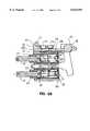
- FIG. 1is a side view of the drill unit that constitutes the cordless, battery operated power surgical tool of this invention which is conventionally known as a drill unit;
- FIG. 2is a side view showing the basic internal components of the drill unit
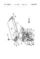
- FIG. 3is an exploded view of the external features of the drill unit
- FIG. 4is an exploded view illustrating how the motor, the motor controller, the trigger assembly and the housing front plate are assembled together;
- FIG. 5is an exploded view of the internal components of the trigger assembly
- FIG. 5Ais an exploded view of the components within a shaft housing of the trigger assembly of FIG. 5;
- FIG. 5Bis a cross sectional view of the trigger assembly of FIG. 5;
- FIG. 6is a an exploded view illustrating how the motor control module is secured to the trigger assembly in order to form the contactless switches of this invention
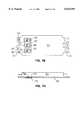
- FIGS. 7A and 7Bare respectively, cross sectional and bottom views of the bottom plate of the motor control module housing and of the magnetic-field sensors seated in the bottom plate;
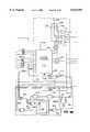
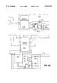
- FIG. 8is a block diagram of the major elements of the motor control circuit
- FIG. 9is a blueprint depicting how FIGS. 9A, 9B, 9C and 9D are assembled together to form a schematic diagram of components forming one particular motor control module;
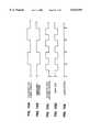
- FIGS. 10A, 10B, 10C, 10D and 10Eare timing diagrams of signals generated by the motor control module to cause the oscillation of the drill unit motor.
- FIGS. 11A, 11B, 11C, 11D and 11Eare timing diagrams of the signals that cause the motor control module to assert the brake signals and of the brake signals themselves.
- FIGS. 1 and 2illustrate the basic components of a cordless, battery operated powered surgical tool of this invention which is often referred to as a drill unit 10.
- Drill unit 10includes a drill unit housing 12 which contains an electrically powered motor 14.
- the drill unit housing 12has a lower section referred to as a handgrip 16.
- a battery 18 contained within the handgrip 16supplies the power required to energize the motor 14.
- Formed integrally with the handgrip 16 and extending along the top of the handgripis a motor section 20 in which the motor 14 is housed.
- Located immediately below the motor 14is a sealed motor control module 22.
- the motor control module 22regulates the application of energization signals to the motor 14 so as to cause the motor to selectively rotate in a first, forward direction, a second, reverse direction and in a third pattern wherein the motor undergoes an oscillatory rotation back-and-forth between the forward and reverse directions.
- energization signalsfor many, but not all, powered surgical tools, when facing the front end of a tool, counter-clockwise rotation is considered to be forward rotation and clockwise rotation is considered to be reverse rotation.
- Trigger assembly 24Located immediately below the motor control module 22 is a trigger assembly 24 that provides the switches that allow an individual to control the actuation of the motor 14 through the motor control module 22.
- Trigger assembly 24has upper and lower vertically aligned trigger switches 26 and 28, respectively, that extend forward of the handgrip 16.
- upper trigger switch 26medical personnel can cause the motor 14 to rotate in the reverse direction and control the speed of the motor's rotation.
- lower trigger switch 23medical personnel can cause the motor 14 to rotate in the forward direction and control the speed of the motor's rotation.
- both trigger switches 26 and 28the motor 14 can be actuated into oscillatory rotation and the speed of the motor's rotation can also be controlled.
- the trigger assembly 24also has a safety lever 30 that extends away from one side of the housing handgrip 16. Depending on the setting of the safety lever 30, the trigger assembly 24 inhibits movement of one or both of the trigger switches 26 and 28 so as to prevent unintended actuation of the motor 14.
- the primary structural component of the drill unit housing 12, now described with respect to FIG. 3,is a weldment 32 which forms the sides of the handgrip 16 and housing motor section 20.
- the front and back ends of weldment 32are open to facilitate the installation of the motor 14, the motor control module 22 and the trigger assembly 24 into the drill unit housing 12.
- a backcap 34is fitted over the open rear end of the weldment 32.
- a front plate 36is secured over the open front end of the weldment 32.
- the motor 14, the motor control module 22 and the trigger assembly 24are all attached to the front plate 36. This subassembly is then fitted into the drill unit housing 12 as part of the process of assembling the drill unit 10 of this invention.
- the trigger assembly 24, as depicted in FIGS. 4 and 5,includes a single-piece trigger housing 38 that is located against the inside surface of the front plate 36 adjacent the lower end of the front plate. Three magnets 39, 40 and 41 are slidably secured to the top of the trigger housing 38 so as to move in response to the actuation of the trigger switches 26 and 28. Sensors 178-182 (FIG. 7B) internal to the motor control module 22 and located above the magnets 39, 40 and 41, monitor the positions of the magnets so as to cause the components internal to the module to apply the appropriate energization signals to the motor 14.
- the trigger housing 38includes upper and lower shaft sleeves 42 and 44, respectively, that are vertically aligned with each other.
- Upper shaft sleeve 42houses the components associated with upper trigger switch 26.
- Lower shaft sleeve 44houses the components associated with lower trigger switch 28.
- An elongated safety sleeve 45is located on one side of the trigger housing 38 between the shaft sleeves 42 and 44 and extends from the forward end of the housing to approximately the midpoint of the housing.
- the safety 45houses some of the components associated with sleeve safety lever 30.
- a head member 47extends upwardly above the forward end of the upper shaft sleeve 42.
- a tail member 48is also integrally attached to the upper shaft sleeve 42 so as to be positioned above and behind the sleeve 42.
- Trigger housing head member 47is formed with a top surface 49.
- Trigger housing tail member 48is formed with a top surface 50 that is coplanar with the top surface 49 of trigger housing head member 47.
- Trigger housing head member 47is further provided with spaced apart guide pins 51 that extend upwardly from the head member top surface 49. As will be described hereinafter, the guide pins 51 facilitate the proper seating of the motor control module 22 on the trigger assembly 24.
- Trigger housing 38is further formed with a pair of parallel rails 52 that extend across the top of the trigger housing upper sleeve 42 between the trigger housing head and tail members 47 and 48, respectively.
- the opposed left and right magnets, magnets 39 and 41, respectively,are each located above separate ones of the rails 52.
- the center magnet, magnet 40is located above and between the rails 52, between the right magnet 39 and the left magnet 41.
- the trigger shaft assembly 56includes a metal-formed shaft housing 58.
- the shaft housing 58is formed with a head end 64 that has a diameter less than that of the main body of the housing 58.
- the head ends 64 of the shaft housings 58are formed with external threading 63. These head ends 64 of the shaft housings 58 extend through the adjacent front plate 36.
- Complementary nuts 65(FIG. 4) are secured over the head ends 64 of the shaft housings 58 that project outside of the front plate 36 so as to fasten the shaft housings 58, as well as the whole of the trigger assembly 24, to the front plate 36.
- a trigger shaft 66is positioned in the shaft housing 58 so as to extend out of the head end 64 of the housing 58.
- the trigger shaft 66is shaped to have a large diameter, generally cylindrically shaped base 68 that is disposed entirely within the shaft housing 58.
- Trigger shaft base 68is further dimensioned to be able to slide in the shaft housing 58 and has a length approximately one-half of the length of the space in which it can slide.
- a shaft stem 70 that is coaxial with the trigger shaft base 68extends forward from the base out of the shaft housing 58 and through the front plate 36.
- a spring 72 seated in the shaft housing 58 behind the trigger shaft base 68biases the trigger shaft 66 so that the trigger shaft stem 70 normally extends out of the shaft housing 58.
- the base 68 of the trigger shaft 66is formed with an axially aligned, rearward opening bore 71 in which the leading end of the spring 72 is seated.
- a generally disk shaped spring retainer 74is located in the rear end of the shaft housing 72 so as to provide a rear stop for the spring 72.
- Spring retainer 74is formed with a center boss 75 around which the spring 72 is seated. The spring retainer is held in position by a C-shaped retaining ring 78 that is seated in a groove 80 formed in the inside wall of the shaft housing 58.
- each switch 26 and 28is formed with a bore, 69 in which the end of the complementary trigger shaft stem 70 is seated.
- a set screw 82 seated in a complementary threaded screw bore 84 formed in each switch 26 and 28is positioned to abut against the side of the trigger shaft stem 70 seated in the trigger switch 26 or 28 in order to secure the switch to the trigger shaft stem 70.
- the left and right magnets 39 and 41, respectively,are mounted in left and right magnet carriers 88 and 90, respectively, that move in unison with the displacement of the trigger shafts 66 as is best shown in FIG. 5.
- the magnet carriers 88 and 90are located on the opposed sides of the trigger housing 38.
- Each magnet carrier 88 and 90is formed out of a single piece of material that is shaped, in part to form a side plate 92.
- the side plate 92 integral with the left magnet carrier 88extends from the axis of the trigger housing lower shaft sleeve 44 to the rail 52 on the right side of the trigger housing 38.
- the side plate 92 integral with right magnet carrier 90extends from the axis of the trigger housing upper shaft sleeve 42 to the top of the rail 52 on the left side of the trigger housing 38.
- a foot 94is attached to the bottom edge of each side plate 92 and extends perpendicularly inward from the side plate. Each foot 94 is secured to the trigger shaft 66 with which the magnet carrier 88 or 90 is associated. Each foot 94 extends through an elongated slot 96 formed in the associated shaft sleeve 42 or 44 and a similar slot 97 formed in the adjacent trigger shaft housing 58. Each foot 94 is seated in a rectangular profile groove 96 formed in the outer surface of the base 68 of the trigger shaft 66 with which the magnet carrier 88 or 90 is associated.
- a pin 98that extends through the magnet carrier foot 94 and into the trigger shaft 66 ensures that the magnet carrier 88 or 90 moves in unison with the displacement of the trigger shaft.
- a head piece 102is attached to the top of each magnet carrier 88 and 90.
- Each head piece 102is generally rectangularly shaped and is positioned to extend over the rail 52 adjacent to the magnet carrier 88 or 90.
- the top of the head piece 102is shaped to define a rectangular recess 104 in which the associated left magnet 39 or right magnet 41 is seated.
- the center magnet 40rides in a center carrier 106 located between the head pieces 102 in which the left and right magnets 39 and 41, respectively, are carried.
- the center carrier 106is a block-like structure that has a center rib 101 that extends downwardly from the main body of the carrier and that extend along the longitudinal axis of the carrier.
- the center carrier 106is further dimensioned to extend rearward of the adjacent magnet carrier head pieces 102 when all of the carriers 88, 90 and 106 are located adjacent the trigger housing head member 47.
- the center carrier 106slides over a straight pin 108 that extends between the head member 47 and tail member 48 of the trigger housing 38. More specifically, one end of straight pin 108 is compression fitted in a bore 103 formed in the head member 47. The opposed end of the pin 108 is compression fitted in a rectangular cut-out 105 formed in the tail member 48. The straight pin 108 is further slidably fitted into a pin bore 109 that extends axially through the carrier center rib 101.
- the center rib 101 of the center carrier 106is dimensioned to extend down to the top surface of the adjacent upper sleeve 42 in order to ensure lateral stability of the center carrier 106 as it is displaced.
- the top surface of the center carrier 106is formed with two, longitudinally aligned rectangular recesses 110 and 112. Two magnets 114 and 116 are respectively disposed in the individual recesses 110 and 112. Magnets 110 and 112 collectively comprise the center magnet 40. Magnets 114 and 116 are arranged in center carrier 106 so that one magnet has a north pole that faces the adjacent motor control module 22 and the second magnet has a south pole that faces the motor control module.
- the center carrier 106 and associated magnets 114 and 116are normally biased toward the trigger housing head member 47 by a spring 115 fitted over straight pin 108.
- the spring 115extends between the trigger housing tail member 48 and the back end of the center carrier 106.
- the center carrier 106is further provided with tabs 117 that project outwardly from the opposed sides of the carrier 106. Each tab 117 is positioned to abut the end surface of the adjacent magnet carrier head piece 102. Consequently, when the actuation of a trigger switch 26 and/or 28 results in the like displacement of the right or left magnet carrier 90 or 88, the rearward movement of the carrier 90 or 88 causes the like rearward movement of center carrier 106.
- the trigger assembly 24is further provided with a safety disk 120 positioned to selectively prevent unintentional actuation of the trigger switches 26 and 28.
- the safety disk 120is housed in a slot 122 defined in the trigger housing in the portion of the housing between the shaft sleeves 42 and 44. More specifically, the safety disk 120 is positioned to be at a location where, when the trigger shafts 66 are in their full forward positions, the disk 120 can abut the rear ends of the trigger shafts 66.
- the safety disk 120is secured to a cylindrical safety shaft 124 by a screw 123.
- Safety shaft 124is rotatably fitted in a shaft bore 121 that extends axially through the portion of the trigger housing 38 between the shaft sleeves 42 and 44.
- the safety lever 30(FIG. 1) is attached to the front end of the safety shaft 124 for rotating the shaft 124 and the safety disk 120.
- Each trigger shaft housing 58is formed with a slot 125 dimensioned to accommodate the safety disk 120.
- the safety disk 120can be rotated into one of three positions.
- the disk 120has a first position wherein it is spaced away from the spaces in both the upper and lower shaft sleeves 42 and 44 in which the associated trigger shafts 68 may slide.
- the safety disk 120has a second position wherein the disk is disposed in the upper shaft sleeve 42 to prevent movement of the reverse trigger shaft 68.
- the safety disk 120is disposed in both shaft sleeves 42 and 44 to prevent movement of both trigger shafts 68.
- the safety diskis held in an appropriate position by a cylindrical lock pin 126. Lock pin 126 is seated in a circular groove formed in the trigger housing safety sleeve 45.
- the lock pin 126is positioned to be seated in one of a number of circular notches 128 formed along the adjacent side of the safety disk 120.
- a curved leaf spring 129 disposed in the safety sleeve 45bears against the lock pin 126 to hold the pin 126 in the notch 128 in which the pin is seated.
- the force imposed by spring 129 to hold the safety disk 120 in positioncan be overcome by the manual displacement of safety lever 30.
- a pair of conductive battery blades 130are secured to the end of the trigger assembly 24.
- the battery blades 130form part of the conductive paths between the battery 18 and the motor control module 22.
- Each battery bladeis formed out of a single piece of conductive metal that is shaped to have an elongated, generally vertically aligned shank 132.
- the individual battery blades 130are suspended to opposed sides of the trigger housing tail member 48 by button head screws 134 that extend through the shanks 132 forming each blade 130.
- Each battery blade 130is further formed with a mounting tab 136 that extends perpendicularly forward of the associated shank 132 at a location approximately one-quarter the distance from the bottom edge surface of the shank.
- Each mounting tab 132is compression fitted in a slot 138, (one slot shown in phantom,) formed on the side trigger housing 38.
- each battery blade 130functions as a male terminal 140 that is seated in a complementary conductive female terminal integral with the battery 18, (female terminal not shown).
- a conductor tab 142extends rearward from each shank 142 adjacent the point the shank is secured to the trigger housing tail member 48.
- Conductor tab 142is formed with an opening 144 to facilitate the securing of an insulated power conductor 146 to the battery blade 130.
- the motor control module 22includes a module housing 150 that is secured to the top of the trigger assembly 22.
- the module housing 150is formed out of a base plate 152, a generally rectangularly shaped corral 154 that forms the sides of the housing and a cover 156.
- the plate 152, the corral 154 and the cover 156 forming the module housingare bonded together to form an interior space, not identified, that is sealed from the outside environment.
- the components forming the control circuit of the drill unit 10 of this inventionare housed in the interior space of the module housing 150.
- bottom plate 152, corral 154 and cover 156are formed of plated, rust-resistant cold-rolled steel.
- Module housing base plate 152is formed with forward and rearwardly extending tabs 160 and 162, respectively, that extend beyond the adjacent surfaces of the housing corral 154.
- Forward tab 160is formed with two spaced apart guide holes 163.
- the motor control module 22is secured to the trigger assembly 24 by a button-head screw 164 that is fitted into complementary, coaxial openings 166 and 167 formed respectively in the base plate forward extending tab 160 and in the trigger housing head member 47.
- the base plate rearward extending tab 162is formed to define a number of parallel cut-out slots 168 that are positioned along the length of the tab. These slots 168 facilitated the securement of fastening members to the module housing base plate 152 that are used to secure the motor control module 22 to the motor 14.
- the housing base plate 152is provided with three rectangular cutouts 172 now described by reference to Figures 7A and 7B.
- Each cutout 172is formed in the housing base plate 152 so as to be axially aligned with and centered over the linear travel path of a separate one of the three trigger assembly magnets 39, 40 or 41.
- the cutouts 172are sealed by a single piece of thin metal seal 174 that is secured to the outer surface of the housing base plate 152.
- the metal forming the seal 174is more magnetically permeable than the metal forming the module housing 150 to which the seal is attached.
- seal 174is formed of a strip of molybdenum that is between 10 and 50 mils thick and, in more preferred versions of the invention, approximately 15 mils (0.015 inches) thick.
- each Hall effect sensor 178, 180, and 182are components integral with the motor control module 22 that regulate the energization of the motor 14. Since each Hall effect sensor 178, 180 and 182 is seated in a cutout adjacent a separate one of the trigger assembly magnets 39, 40, and 41, each sensor is paired with a separate one of the magnets. When an appropriate signal is applied across each Hall effect sensor 178, 180 or 182, a signal representative of the magnetic field in the vicinity of the sensor is generated by the sensor. In one preferred version of this invention, sensors 178 and 182 are magnetically unipolar and sensor 180 is magnetically bipolar.
- each Hall effect sensor 178, 180, and 182generates a signal representative of the position of the of complementary moving trigger assembly magnet 39, 40 or 41, respectively, relative to the sensor.
- the signals produced by the Hall effect sensors 178, 180 and 182are then, in turn, used by other components of the motor control module 22 as input signals for regulating the application of energization signals to the motor 14.
- FIGS. 3 and 4it can be seen that the rear end of the motor 14 secured to the backcap 34 by a decorative screw 173.
- An O-ring 175s seated in a groove 175 formed in shaft of the screw 173 in order to hold the screw in position.
- the front end of the motor 14extends through a larger, circular opening 186 formed in the front plate 36.
- the motor 14is held in position by a ring nut 37.
- a cylindrical lock pin 187is disposed between the motor 14 and the front plate 36.
- the lock pin 187is seated in complementary semi-circular notches 188 and 189 formed, respectively, in the side of the motor and the surface of the front plate 36 that defines opening 186.
- a collet, a chuck or a saw attachmentthat may be secured to the exposed end of the motor rotor 203 (FIG. 8) that extends through the front plate 36.
- the collet, the chuck or the saw attachmentfunctions as the element of the drill unit 10 to which the complementary cutting attachment with which the drill unit is used is attached.
- element 14is generally representative of the motor of the drill unit 10 of this invention that integral with the motor is a gear assembly for transferring the rotational moment generated by the motor rotor 203 to the collet, the chuck or the saw attachment.
- An L-shaped bracket 183extends downwardly and then forward from the rear end of the motor 14.
- a first set of button head screws 164secure the bracket 183 to the rear end of the motor 14. These screws 164 extend through complementary slots 184 formed in the bracket 183 and are secured in complementary bores 185 formed in the rear end of the motor 14.
- a second set of screws 164secure the rearward extending tab 162 of the motor control module housing 150 to the bracket 164 so as to hold the rear of the housing in position. These pins 164 are seated in the complementary slots 168 formed in the tab 162.
- a number of conductive pins 190that extend out of the opposed front and rear ends of the module housing 150. Conductive pins 190 serve as part of the conductive paths for the signals applied to the motor 14 and the signal received from the motor 14 that are employed to monitor the state of the motor. Each conductive pin 190 extends out through an opening in the housing corral 154; a glass or other non-conductive material is used to form an environmental seal around the pins, (corral openings and glass seal not shown).
- a first shielded wire 192extends from one of the battery blades 130 to the rearward extending tab 162 integral with the housing base plate 152.
- a second shielded wire 192extends from the other battery blade 192 to one of the rearwardly extending conductive pins 190. Additional wires 194 that extend from the rear of the motor 14 to other of the rearwardly extending conductive pins 190 serve as the conductive paths to the windings forming the motor 14.
- the motor 14is a three phase, full-wave, brushless, pulse DC motor.
- the motor 14includes three windings 202a, 202b, and 202c that are tied together at one end.
- the motor 14is capable of being driven by a battery 18 capable of providing DC pulses between 8 and 15 Volts potential and at a current of between 2 and 40 Amps depending on the load being driven.
- the motor 14is driven by pulses having a potential of 9.6 Volts.
- the motor 14is formed with a lamination stack with externally, outwardly facing teeth, not illustrated. This feature of the motor 14 facilitates the automated wrapping of the windings 202 around the lamination stack during the assembly of the motor.
- Motor 14also includes a magnetized rotor 203, illustrated diagrammatically in FIG. 8.
- the outer diameter of the rotor 203, the portion forming the rotor magnetsis no greater than 1.0 inches. In more preferred versions of the invention, the outer diameter of the rotor 203 is 0.6 inches or less.
- the motor controller module 22includes a number of individual circuits that collectively apply DC signals at appropriate pulse rates to the motor windings 202.
- the potential from the battery 18is applied to the windings 202 through a power driver circuit 204 connected directly to the windings.
- the power driver circuit 204in addition to being connected to the motor windings 202, is connected to the positive and negative terminals of the battery 18 represented respectively by terminals 206 and 208.
- the power driver circuit 204ties winding 202a to the positive battery terminal 206.
- the power driver circuit 204rapidly opens and closes the connection between another one of the windings in this example either winding 202b or winding 202c, to the negative battery terminal 208.
- pulsed DC signalsare applied through two of windings in order cause the rapid development and collapse of the magnetic field around the windings used to actuate the motor rotor 203.
- the fieldwould be developed around windings 202a and 202b or windings 202a and 202c.
- a high side driver circuit 210is connected to the power driver circuit 204 for applying the signals required to cause the switching needed to connect the windings 202 to the positive battery terminal 206.
- a low side driver circuit 212is connected to the power driver circuit 204 for applying the signals required to cause the switching need to connect the windings 202 to the negative battery terminal 208.
- a current sensor circuit 214is also connected to the power driver circuit 204.
- the current sensor circuitmonitors the current through the motor windings and generates a CUR+ signal which is a volts/amp signal representative of the current drawn by the motor.
- the CUR+ signalis then supplied to a motor controller circuit 216.
- the motor controller circuit 216determines which windings 202a, 202b or 202c are to be energized and the rate at which the windings are to be energized.
- the motor controller circuit 216receives input signals from a number of sources in addition to the current sensor circuit 214. Based on these input signals, the motor controller circuit 216 generates commands to the high and low side driver circuits 210 and 212, respectively, to cause the appropriate windings 202a, 202b or 202c to be tied across the battery 18 at the appropriate on/off duty cycle. Also, depending on the state of the input signals, the motor controller circuit 216 can command that each winding 202a, 202b and 202c be tied to ground. This causes a braking electromotive force to be generated around the motor rotor 203 so as to foster the deceleration of the motor 14.
- the majority of the input signals applied to the motor controller circuit 216originate from a direction controller circuit 218.
- the direction controller circuit 218receives as input the signals generated by the Hall effect sensors 178, 180 and 182 integral with the motor controller module 22.
- Hall effect sensor 178the sensor that monitors the position of left magnet 39, generates an output signal indicating if the motor 14 is to be driven in forward or oscillatory rotation.
- Hall effect sensor 182the sensor that monitors the position of right magnet 41, generates an output signal indicating if the motor 14 is to be driven in reverse or oscillatory rotation.
- Hall effect sensor 180the sensor that monitors the position of center magnet 40, generates an output signal indicating the speed at which the motor is to be driven.
- the direction controller circuit 218Based on the states of the sensor signals, as well as other signals to be described hereinafter, the direction controller circuit 218 generates signals to the motor controller circuit 216 that inform the motor controller circuit of the direction in which the motor 14 should be driven and the speed at which the motor should rotate. Also, when the motor 14 driven in oscillatory rotation, the direction controller circuit 218 selectively regulates the volts/amp ratio upon which the current sensor circuit 214 basis the CUR+ signal applied to the motor controller circuit 216.
- motor sensors 220are Hall effect sensors located adjacent the windings 202. Each sensor 220 generates pulse signals as a function of the proximity of the magnetic field of the rotor 203 relative to the sensor.
- the signals generated by the motor sensors 220are applied to the motor controller circuit 216 and a tachometer circuit 222.
- the tachometer circuit 222generates output signals representative of motor state. These output signals from the tachometer circuit 222 are then applied to the motor controller circuit 216 and the direction controller circuit 218 as input signals. As will be described hereinafter, the motor controller circuit 216 and the direction controller circuit 218 generate their own control signals based on these motor state signals.
- the motor controller module 22 of this inventionalso includes a brake controller circuit 224.
- the brake control circuit 224monitors some of the signals generated by the motor controller circuit 216. Based on this signal monitoring, the brake controller circuit 224 selectively generates a BRAKE-ENABLE (BE) signal to the motor controller circuit 216 so as to cause the motor controller circuit to initiate the braking of the motor 14.
- BEBRAKE-ENABLE
- the voltage regulatoris connected to the battery 16 and is used to boost the battery voltage to a level needed to energize the individual signal processing components forming the motor control module 22.
- some voltage regulatorsare used to provide a +12 V Vcc voltage.
- One such voltage regulatorcan be assembled with an MAX734C/D DC-to-DC voltage converter chip manufactured by Maxim. The Vref voltage upon which many of the signal comparisons described hereinafter are based is supplied by the motor controller circuit 216.
- FIGS. 9A, 9B, 9C and 9Dwhen assembled together, form a schematic diagram of the primary components of the motor controller module 22 described above with reference to FIG. 8.
- the Hall effect sensors 178, 180, and 182 employed to monitor the state of the trigger assembly magnets 39, 40, 41, respectivelyare depicted as bi-polar transistors.
- the signals produced by the Hall effect sensors 178-182are applied to the direction controller circuit 218.
- the collectors of Hall effect sensors 178 and 182the sensors employed to monitored the desired forward/reverse/oscillate state of the motor 14, are connected to separate pull-up resistors 232 and 234, respectively.
- the opposed end of each pull-up resistor 232 and 234is tied to the Vref voltage source.
- Hall effect sensors 178 and 182are thus configured so that when the magnets 39 and 41 associated with each sensor are in their at-rest state, the sensors produce a relatively high impedance output. Consequently, when each magnet 39 and 41 is in this state, high signals appear at the junctions of each sensor 178 and 182 with its associated pull-up resistor 232 and 234, respectively.
- the trigger assemblyis configured so that each magnet 39, 40 and 41 can travel approximately 350 mils.
- Hall effect sensors 178 and 182are configured so that once the associated magnet 39 or 41 is displaced approximately 65 to 165 mils from its at-rest position, the sensor will generate a signal sufficient to cause the signal at the pull-up resistor junction to transition to a low signal that can be detected by the downline components.
- Gate 236produces a FORWARD/REVERSE (F/R) signal that is applied to the motor controller circuit 218.
- NAND gate 238selectively generates an OUTPUT-ENABLE (OE) signal to the motor controller circuit 216.
- OEOUTPUT-ENABLE
- NAND gate 238only generates the OUTPUT-ENABLE signal if one of the Hall effect sensors 178 or 182 generate a signal indicating the complementary trigger assembly magnet 39 or 41 has been generated. This feature of the driver controller circuit 218 thus prohibits the inadvertent actuation of the motor controller circuit 216 and the resultant unintended actuation of the motor 14 if neither trigger switch 26 nor trigger switch 28 have been depressed.
- the signal present at the collector/pull-up resistor junction of sensor 182, the sensor associated with the magnet 41 actuated in response to a reverse or an oscillate motor command,is applied to the second input of NAND gate 238.
- the output signal from sensor 182also functions as a RESET (RST) signal that is applied to a counter 240 that also forms part of the direction controller circuit 218.
- RSTRESET
- counter 240is a falling-edge triggered counter.
- the counter 240receives clock pulses the signals generated by the tachometer circuit 222 that are representative of the incremental rotation of the motor rotor 203.
- a first one of the output signals generated by the counter 240is applied to the second input of NOR gate 236.
- a second output signal from the counter 240a signal having twice the frequency of the first output signal, is applied to one of the inputs of a three-input NOR gate 242.
- the other two input signals applied to NOR gate 242are the output signals produced by the forward and reverse Hall effect sensors 178 and 182, respectively.
- the output signal from NOR gate 242is branched to a ground through a series-connected capacitor 244 and a forward-biased diode 246.
- a resistor 248is connected in parallel across the diode 246.
- a n-channel FET 250is also tied across diode 246. More specifically the drain and gate of FET 250 are tied respectively to the anode and cathode of diode 246.
- the capacitance of capacitor 244 and the resistance of resistor 248are selected so that each time the output from NOR gate transitions from low to high, a pulse signal is placed across the gate of FET 250 sufficient to close the FET for a period ranging from 10 to 75 msec. In more preferred versions of the invention the pulse is applied across the gate of FET 250 to close the FET for approximately 60 msec.
- the center-position Hall effect sensor, Hall effect sensor 180produces an output signal representative of the user-selected rotational speed of the motor 14.
- the output signal from Hall effect sensor 180is taken off the sensor's emitter through a resistor 254.
- a capacitor 258is connected between the end of resistor 254 distal from the sensor 180 and ground.
- the signal present at the junction of resistor 254 and capacitor 258is an analog USER-SPEED (US) signal representative of the rotational rate at which the motor 14 should be driven.
- USUS
- the conductor over which the USER-SPEED signal travelsis connected to both the motor controller circuit 216 and to the drain of FET 250.
- Hall effect sensor 180is a bipolar sensor responsive to both positive and negative gaussian fields that are present in the vicinity of the sensor.
- Magnet 40is formed out of the two opposed magnets 114 and 116 in order to enhance the sensitivity of the sensor 180.
- magnet 40has a pre-travel displacement of approximately 165 mils from its at-rest position before the sensor 180 causes a shift in the USER-SPEED signal. Magnet 40 then travels approximately a 75 mil distance, referred to as the variable speed travel, during which the output of sensor 180 will cause a complete transition of the USER-SPEED signal.
- the remaining, approximately 75 mils, of the travel of magnet 40will not cause any additional change in the output of the sensor 180 or the USER-SPEED signal.
- the movement of the magnet 40 in this region, as well as of the associated magnet(s) 39 and/or 41is referred to as post-travel movement.
- the tachometer circuit 220essentially consists of a single tachometer chip 260.
- One suitable tachometer chip 260is the MC33039 tachometer chip manufactured by Motorola.
- the tachometer chip 260receives as input signals the pulse signals produced by the motor sensors 220, identified as signals SA, SB and SC. In response to the signals produced by the motor sensors 220, tachometer chip 260 produces variable frequency DC pulses, a MOTOR-PULSE (MP) signal, representative of motor speed.
- the MOTOR-PULSE signalis applied to the direction controller circuit counter 240 to function as the counter clock signals.
- the MOTOR-PULSE signal generated by the tachometer chip 260are also applied to the brake control circuit 224.
- the tachometer chip 260also produces a pulse DC MOTOR-SPEED (MS) signal representative of motor speed.
- the MOTOR-SPEED signalis a pulse signal that is always on for a fixed unit of time in a variable time period that varies inversely with measured motor speed.
- the MOTOR-SPEED signalis applied to the motor controller circuit 216 through a resistor 262.
- a small offset voltageis applied to the conductor over which the MOTOR-SPEED signal is applied to the motor controller circuit 216.
- the offset voltageis taken off a voltage divider which consists of three series connected resistors 263, 264 and 265. Resistor 263 is connected to the Vref voltage source and resistor 265 is connected to ground.
- the offset voltageis taken off the junction of resistors 263 and 264 and is applied to the motor controller circuit through a resistor 266. This offset voltage is applied to the MOTOR-SPEED signal so that an analog, integrated form of the MOTOR-SPEED signal can be accurately compared to the user-selected USER-SPEED signal.
- the motor controller circuit 216includes a motor control chip 272.
- One particular motor control chip 272 from which invention has been constructedis the MC33035 brushless DC motor control chip manufactured by Motorola.
- the motor control chip 272receives as input signals the SA, SB and SC pulse signals generated by the motor sensors 220, the OUTPUT-ENABLE, the FORWARD/REVERSE and the USER-SPEED signals produced by the direction controller circuit 218 and the MOTOR-SPEED signal generated by the tachometer chip 260.
- the motor control chip 272also receives the BRAKE-ENABLE (BRK-E) signal from the brake controller circuit 224 and the CUR+ and CUR signals representative of the current drawn by the motor 14 from the current sensor circuit 214.
- BRAKE-ENABLEBRK-E
- the motor control chip 272In response to receiving the foregoing input signals, the motor control chip 272 generates the signals that result in the motor windings 202 being selectively tied to the battery 18 in order to control the rotational movement of the motor 14.
- the primary signals motor control chip 272generates are a set of HIGH-SIDE-CONTROL (HSC) signals and a set of LOW-SIDE-CONTROL (LSC) signals.
- the HIGH-SIDE-CONTROL signalsare applied to the high side driver circuit 210 to cause the windings 202 to be individually connected to the positive battery terminal 206.
- the individual HIGH-SIDE-CONTROL signalswhich are asserted high, are actually applied to three identical pull-up resistors 268 that are connected to receive the Vref voltage.
- the signals present at the junctions of resistors 268 and the HIGH-SIDE-CONTROL conductors extending from motor control chip 272are applied to the input terminals of three separate NOR gates 273 also part of the motor controller circuit 216.
- the second input to each NOR gate 273is a HIGH-DRIVE-INHIBIT (HDI) signal that is selectively asserted by the brake controller circuit 224.
- the output signals from NOR gates 273are applied to separate inputs of the high side driver control circuit 210.
- the LOW-SIDE-CONTROL signalsare applied to the low side driver circuit 212. Normally, at any given instant only a single LOW-SIDE-CONTROL signal is asserted to tie a single one of the windings 202a, 202b or 202c to the negative battery terminal. However, when the motor control chip 272 receives a BRAKE-ENABLE signal, the chip 272 will assert LOW-SIDE-CONTROL signals so as to tie each winding 202a, 202b and 202c to ground.
- the motor control chip 272in addition to generating the signals required to tie the motor windings 202 to either a voltage source or ground, also generates a number of signals used by the other components forming the motor control module 22.
- the motor control chip 272is the source of the Vref voltage reference signal.
- the motor control chipalso generates a fixed frequency, sawtooth profile OSCILLATOR (OSC) signal. (Resistor and capacitor used to establish the frequency of the OSCILLATOR signal not shown.)
- Motor control chip 272also generates an analog ERROR (ERR) signal representative of the difference between the measured motor speed and the speed at which the user actually wants the motor to be driven.
- the ERROR signalis based on the difference in magnitude between the USER-SPEED signal and the MOTOR-SPEED signal.
- the motor controller chip 272has an internal high-gain op amp, not illustrated, to which the MOTOR-SPEED and USER-SPEED signals are applied as separate inputs.
- the out-put of this op amp, the ERROR signalis supplied as feedback to the motor control chin 272 input to which the MOTOR-SPEED signal is applied.
- the feedback of the ERROR signalis through a resistor 275.
- a capacitor 277 tied across resistor 275integrated the pulse signals forming the tachometer-generated MOTOR-SPEED signal to present the analog, integrated form of the MOTOR-SPEED signal to the appropriate input on the motor control chip 272.
- the gain of the op amp that generates the ERROR signalis between 10 and 100, in more preferred versions of the invention, the gain is approximately 20.
- the motor control circuit 216also includes a comparator 274.
- Comparator 274receives at its non-inverting input the ERROR signal from motor control chip 272.
- the OSCILLATOR signalis applied to the inverting input of comparator 274.
- the comparator 274asserts a BRAKE-TRIGGER (BRK-T) signal to the brake controller circuit 224.
- BRAKE-TRIGGERBRAKE-TRIGGER
- the high side driver circuit 210selectively applies an overdrive voltage to the individual high-side switches integral with the power driver circuit 204 in order to selectively tie the motor windings 202a, 202b and 202c to the positive batter terminal 206.
- the high side driverincludes a boost regulator 278 that is primarily responsible for providing individual DC pulses that are boosted to a potential +12 V above the potential across the battery 18.
- One suitable boost regulator 278is the MAX620C/D boost regulator manufactured by Maxim.
- Boost regulator 278has three inputs each of which receives a different one of the three output signals produced by the individual motor controller circuit NOR gates 273.
- the boost regulator 278Depending on which NOR gate 273 asserts a high signal, the boost regulator 278 generates a gate signal to a specific high-side FET internal to the power driver circuit 204 as will be discussed hereinafter.
- the individual gate signalsare applied to each FET through three pairs of series connected resistors, each pair identified as resistor 280 and resistor 282.
- the low side driver circuit 212generates the high current pulses required to switch the low side FETs internal to the power driver circuit 204 as will be discussed hereinafter.
- the low side driver circuitconsists of an input programmable gate driver chip 288 such as an TC4469 manufactured by Telcom.
- the gate driver chip 288is capable of generating high current, approximately 1.5 A, pulses that can be applied to FETs in order to rapidly force the FETs in and out of conduction. This rapid switching is needed because, during operation of the drill unit it is often necessary to selectively connect and disconnect the motor windings 202 to the negative battery terminal 208.
- the rise and fall times of the FETs switched by the drive chip 288should be 100 nanosec or less.
- the gate driver chip 288has three input terminals at which the individual LOW-SIDE-CONTROL signals from the motor control chip 216 are received. Depending on which LOW-SIDE-CONTROL signal is received, gate driver chip 288 generates a high-current signal over one of three output terminals to one of the FETs internal to the power driver circuit 204.
- Gate driver chip 288has a fourth input terminal over which the signal produced by driver controller circuit NOR gate 242 is received. Whenever NOR gate 242 asserts a low signal, the gate driver chip 288 asserts a fourth high current pulse out of a fourth output terminal to the current sensor circuit 214 for a purpose to be explained hereinafter. The application of a high signal to the fourth input terminal of gate driver chip 288 thus causes the chip to negate the output of a high current pulse. Thus, the application of a high signal to the fourth terminal of the gate driver chip 283 causes an opposite response than what occurs when a high signal is applied to one of the first three input terminals of chip 288.
- the power driver circuit 204has a num ber of FETs that are connected to the winding conductors 286 which connect each winding 202a, 202b or 202c to either the positive or negative battery terminal 206 or 208, respectively.
- Three n-channel FETs 292, 294, and 296are tied between the positive battery terminal 206 and the individual conductors 286a, 286b and 286c, respectively, for selectively applying the battery voltage to an individual windings 202a, 202b or 202c.
- the gate of each FET 292, 294 and 296is connected to a separate one of the output terminals of the boost regulator 278 through an individual one of the series-connected resistors 280 and 282.
- the power driver circuit 204further includes three identical zener diodes 284a, 284b 284c.
- the anodes of diodes 284a, 284b and 284cis connected to the source of a separate one of the FETs 292, 294 and 296 respectively.
- the cathode of each diode 284a, 284b and 284care connected to the gate of the associated FET 292, 294 and 296, respectively through the resistor 282 to which the gate is connected.
- Each diode 284prevents burn out of the associated FET 292, 294 or 296 in the event gate-tosource voltage across the FET exceeds a selected voltage, in some versions of the invention, approximately 20 volts.
- Capacitors 298 and 299provide high pass filtering of the voltage applied from the battery 18 in order to minimize the application of uneven voltages to the windings 202.
- Three n-channel FETS 304, 306 and 308selectively tie the motor windings 202 to the negative battery terminal 208.
- Each FET 304, 306 and 308is connected to a separate one of the windings 202a, 202b and 202c, respectively, through a separate one of the conductors 286a, 286b and 286c, respectively.
- the gates of each FET 304, 306 and 308are each connected to an individual one of the output terminals of the gate driver chip 288.
- the gates of FETs 304-308are connected to the gate driver chip 288 through separate, identical resistors 309.
- FETs 304, 306 and 308Connected in parallel with FETs 304, 306 and 308 to conductors 286 are three additional n-channel FETS 310, 312, and 314, respectively.
- the gate of each FET 310, 312 and 314receives the signal applied to the gate of the FET 304, 306 or 308, respectively, with which it is paired.
- FETs 310-314are thus turned on only when their complementary FETs 304-308 are placed in a like state in order to monitor the current flow through the associated winding 202a, 202b or 202c.
- the sources of FETs 310, 312 and 314are tied to a common conductor 316 that is connected to the current sensor circuit 214.
- the current sensor circuit 214includes a resistor 318 through which the current through conductor 316 is forced to ground.
- Current sensor circuit 214includes a resistor bridge formed of series connected resistors 320 and 322. One end of the resistor 320-resistor 322 bridge is tied between the junction of the FETs 310-314 and resistor 318. The opposed end of the resistor bridge is tied to ground (the negative battery terminal 208).
- a pair of parallel connected resistors 324 and 326 as well as a conductor 328are connected between conductor 316 and the bridge formed by resistors 320 and 322.
- a resistor 340 and an n-channel FET 342are connected in parallel across bridge resistor 322. The gate of FET 342 is connected to the gate driver chip 288 to receive the high current output pulse generated in response to the assertion of the NOR gate 242 high signal.
- Resistor 340has a resistance that is substantially less than that of resistor 322. In some versions of the invention resistor 322 has a resistance approximately 30 times greater than that of resistor 340. Consequently, when FET 342 is closed the volts/amp ratio upon which the CUR+ signal is based is substantially less than the volts/amp ratio when the FET 342 is open and resistor 340 is no longer tied to ground.
- the signal present at the junction of resistors 320, 322 and 340is applied to the motor control chip 272 as the CUR+ sensed current signal.
- the ground conductor tied to the negative battery terminal, conductor not identified,is applied to the motor control chip 272 as a CUR- signal.
- the signal out of the current sensor circuitwill continue to be referred to as the CUR+ signal.
- a capacitor 344 connected across resistor 340 and FET 342removes high frequency spikes from the CUR+ signal.
- the brake controller circuit 224includes a diode 352 to which the BRAKE-TRIGGER signal from comparator 274 is applied.
- a resistor 354 and a capacitor 356are connected in parallel between the cathode of diode 252 and ground. Resistor 354 and capacitor 356 are selected to hold the signal at the cathode of diode 352 high in the event the BRAKE-TRIGGER signal, a low-asserted signal, is momentarily asserted.
- NAND gate 358The signal present at the cathode of diode 352 is applied to both inputs of a NAND gate 358 so that the gate functions as an invertor.
- the output signal from NAND gate 358is applied to the second inputs of the motor controller circuit NOR gates 273 as the HIGH-DRIVE-INHIBIT signal.
- the output signal from NAND gate 358is also applied to both inputs of a second NAND gate 360 so that the signal is inverted back into the state it was in before application to the first NAND gate 358.
- NAND gates 358 and 360are Schmitt trigger gates so as to substantially reduce signal bounce of the output signal.
- the output signal from NAND gate 360is applied to separate inputs of first and second three-input NOR gates 362 and 364, respectively.
- the output signal of the first NOR gate, NOR gate 362is applied to the clock input of a counter 366, also part of the brake controller circuit.
- NOR gate 362receives the slowest cycling, high count, output signal from the counter 366.
- counter 366is a trailing edge triggered counter.
- a comparator 368supplies the third input signal to NOR gate 362.
- the input to the non-inverting input to the comparator 368is a reference voltage. In this version of the invention, that reference voltage is taken off the junction between resistors 264 and 265.
- the OSCILLATOR signal from motor control chip 272is applied to the inverting input of comparator 368.
- a NAND gate 370supplies a reset signal to counter 366 as well as the second input signal to NOR gate 364.
- a first input to NAND gate 370is the MOTOR-PULSE signal from the tachometer chip 260.
- the second input to the NAND gate 370is the signal received from one of the motor sensors 220.
- the third input to NOR gate 364is the aforementioned slowest cycling count signal asserted by counter 366.
- the output signal asserted by NOR gate 364is the BRAKE-ENABLE signal that is applied to the motor control chip 272.
- the drill unit 10 forming the cordless, battery operated powered surgical tool unit of this inventionis used like conventional drill units. Prior to the drill unit 10 being used for a specific medical procedure, medical personnel secure the appropriate cutting attachment to the motor rotor 203. The surgeon then uses the tool by actuating the appropriate trigger switch 26 or 28 to cause either forward or reverse motion of the motor 16. The actuation of the trigger switch 28 or 26 causes the like actuation of the associated direction left or right magnet 39 or 41, respectively. Since the carrier 106 holding the center magnet 40 is configured to moved by the carriers 88 and 90 that, respectively, hold the left and right magnets, the center magnet 40 is displaced with the like displacement of either the left or right magnet.
- the displacements of magnets 39, 40 and 41are monitored by the Hall effect sensors 178, 180 and 182, respectively which are contained in the sealed motor control module housing 150. If neither trigger switch 28 nor 26 are actuated, high signals are present at the ends of pull-up resistors 232 and 234 distal from the Vref voltage source. These signals are applied to the inputs of NAND gate 238. When the drill unit 10 is in this state, NAND gate 238 thus asserts a low, OUTPUT-ENABLED signal to the motor control chip 272. The receipt of the OUTPUT-ENABLE signal by the motor control chip 272, disables the chip so as to prevent the inadvertent application of energization voltages to the motor windings 202.
- the default state for the direction controller circuit 218is to generate a FORWARD/REVERSE state, signal a reverse direction signal, to the motor control chip 272.
- the change in signal state of the associated Hall effect sensor 178causes the signal present at the collector of Hall effect sensor 178 to transition from high to low. This transition causes a like transition of the output signal from NAND gate 238 from OUTPUT-ENABLE to OUTPUT-ENABLE. The transition to the OUTPUT-ENABLE signal serves to enable the motor control chip 272.
- the low signal present at Hall effect sensor 178is also applied to the second input of NOR gate 236. Since the first input of NOR gate 236 is likewise receiving a low signal from counter 240, the output of the gate transitions from the FORWARD/REVERSE state signal to a FORWARD/REVERSE state signal. The FORWARD/REVERSE signal applied is thus applied to the motor control chip 272 which, in turn, interprets the signal as a command to actuate the motor 14 into forward rotation.
- the depression of trigger switch 28also results in a like displacement of the center magnet 40.
- the signal produced by the associated Hall effect sensor 180begins to transition from a low state. This signal is applied to the motor control chip 272 as the USER-SPEED signal.
- the motor control chip 272periodically asserts the HIGH-SIDE-CONTROL and LOW-SIDE-CONTROL signals at the appropriate frequency in order to cause the motor 14 to rotate at the desired speed.
- NOR gate 242in this state serves to invert its third input signal, the second output signal generated by counter 240.
- a FORWARD/REVERSE signalis applied to the motor control chip 272 from NOR gate 236. Since the counter 240 is enabled, the MOTOR-PULSE signal generated by the tachometer chip 260, and applied to the-counter as a clock signal, cause the count outputted by the counter to advance. After a given number of received individual MOTOR-PULSE signals are received by counter 240, the first signal from the counter transitions from low to high as represented by the timing diagram FIG. 10A.
- the counter 240is programmed to transition the first output signal after MOTOR-PULSE signal pulses indicative of between 270° to 720° of motor rotation have been received. In more preferred versions of the invention, the counter 240 transitions the first output signal after MOTOR-PULSE signal pulses indicative of approximately 417° of motor rotation have been received.
- the first output signal from counter 240is the signal that is applied to the second input of NOR gate 236. Consequently, NOR gate 236 transitions from asserting the FORWARD/REVERSE state signal to assert the FORWARD/REVERSE state signal as is represented by FIG. 10B.
- the direction signal asserted by the direction controller circuit 218 and applied to the motor controller circuit 216changes state. This signal state change, in turn, causes the motor controller circuit 216, and in particular the motor control chip 272, to assert signals that cause the motor 14 to reverse its direction of rotation.
- the second output signal from counter 240clocks at a frequency twice that of the rate at which the first output signal clocks.
- the second output signal from counter 240undergoes a high-to-low transition.
- the second output signal from the counteris applied to the third input of NOR gate 242. Since at the time prior to this signal transition, the second output signal was in a high state, NOR gate 242 was asserting a low signal as is represented by FIG. 10D. Consequently, the transition of the second output signal from counter 240 low causes NOR gate 242 to undergo a low-to-high signal state transition.
- a first effect of the low-to-high signal state transition of the output of NOR gate 242is that it causes a pulse to appear across the gate of FET 250 sufficient to momentarily tie the drain of the FET 250 to ground. Since the USER-SPEED signal generated by Hall effect sensor 180 is tied to the drain of FET 250, the USER-SPEED signal is thus momentarily forced low as is represented by FIG. 10E. Thus, at the moment the FORWARD/REVERSE signal applied to the motor control chip 272 changes state, a low, zero-speed, USER-SPEED signal is applied to the motor control chip 272.
- the application of the zero-speed USER-SPEED signal to the motor control chip 272has two effects. First, in response to the zero speed USER-SPEED signal, the motor control chip 272 at least momentarily ceases the assertion of LOW-SIDE-CONTROL signals that cause the actuation of the motor 14. This gives the motor rotor some time to slow and then stop so that the rotor can smoothly reverse the direction of rotation.
- the motor control chip 272will generate an ERROR signal to the comparator 274 sufficient to cause the comparator to assert the BRAKE-TRIGGER signal.
- the assertion of the BRAKE-TRIGGER signalresults in the brake controller circuit 224 asserting the BRAKE-ENABLE signal to the motor control chip 272.
- the motor controller chip 272will, in turn, generate the LOW-SIDE-CONTROL signals needed to cause the braking, the deceleration, of the motor rotor 203.
- the motor control chip 272not only negates the application of energization signals that cause the rotor to be abruptly forced into reverse rotation.
- the motor control chip 272also asserts control signals that cause the rotor 203 to slow down.
- the rotor 203will be turning either relatively slowly or not at all so that the initial reverse motion of the rotor will not result in significant vibration-inducing mechanical shock.
- a second effect of the transition of the output of NOR gate 242 from low to highis that the signal gate 242 applies to the fourth input of gate driver chip 288 also goes low. Consequently, the gate driver chip 288 ceases to assert the requisite high current gate driver signal needed to hold FET 342 closed.
- the opening of FET 342causes the current sensor circuit 214 to produce the CUR+ based on the higher of the two volts/amp ratios. As a result, a larger magnitude CUR+ signal is presented to the motor control chip 272.
- the motor control chip 272upon receiving this larger CUR+ signal, in turn limits the application of energization signals to the windings so as to prevent the "apparent" measured current from not exceeding a predefined maximum current draw.
- the motor control chip 272further only asserts control signals that limit the current the drawn by the motor 14.
- the second output signal from counter 240transitions from low back to high. As shown by FIG. 10D, this causes an opposite change in the state of the signal asserted by NOR gate 242.
- the low signal from NOR gate 242is applied to the gate driver 288 which, in turn, asserts the high current signal required to close FET 342. Consequently the current sensor circuit 214 returns to generating the CUR+ signal based on the lower volts/amp ratio.
- a lower CUR+ signalis again presented to the motor control chip 272.
- the motor control chip 272is thus then able to assert the HIGH- and LOW-SIDE-CONTROL signals that accelerate the motor rotor 203 higher speeds, the accelerations that cause the motor to draw more current.
- comparator 274normally asserts a high, BRAKE-TRIGGER signal. Consequently a high signal is asserted by NAND gate 360. The high signal produced by NAND gate 360 is applied to the inputs of NOR gates 362 and 364.
- the high signal produced by NAND gate 360inhibits the assertion of clock pulses by NOR gate 362 to counter 366. This high signal also prevents NOR gate 364 from asserting a BRAKE-ENABLE signal.
- this arrangement of the brake controller circuit 224 of this inventionprevents the brake controller from asserting a BRAKE-ENABLE signal to the motor control chip 272 unless the motor control chip has first generated some signals indicating the motor rotor 203 is in motion and requires the application of a braking force.
- the signals present at the input of comparator 274may cause the comparator to assert the BRAKE-TRIGGER signal. This signal is asserted low to the brake controller circuit 224. After approximately 10 msec, the time it takes capacitor 256 to discharge, NAND gate 358 transitions from low to high. The high signal from NAND gate 358 is then applied to the motor control circuit NOR gates 273 as the HIGH-DRIVE-INHIBIT signal. As a result of the application of the HIGH-DRIVE-INHIBIT signal, the NOR gates 273 are thus locked to a low output signal.
- the NOR gates 273are locked out from asserting control signals to the boost regulator 278 that would cause the boost regulator to assert the signals necessary to tie the motor windings 202 to the positive battery terminal 206.
- the brake controller circuit 224 and the motor controller circuit 216cooperate to prevent the motor windings from being tied to the positive battery terminal 206.
- NAND gate 358The high signal asserted by NAND gate 358 is then inverted by NAND gate 360. This low signal is applied to separate inputs of NOR gates 362 and 364. Normally, two high signals are not simultaneously-presented to the inputs of NAND gate 370. Consequently, NAND gate 370 normally asserts a high signal.
- the high signal from NAND gate 370is applied to the counter 366 as the RESET signal and as second input signal to NOR gate 364. Since NAND gate 370 normally asserts the RESET signal, counter 366 normally likewise outputs low signals.
- the low-state output signal from counter 366is applied to both the second input of NOR gate 362 and the third input to NOR gate 364.
- NOR gate 364two of the three input signals to NOR gate 364 are low.
- the remaining signalis the signal from NAND gate 370.
- this signalis normally a high signal.
- both input signals presented to NAND gate 370are periodically simultaneously high signals.
- NAND gate 370asserts a low signal to the NOR gate 364.
- all three inputs to NOR gate 364are low so as to cause the gate to assert a BRAKE-ENABLE signal to the motor control chip 272. Since the output signal from NAND gate 370 is only periodically low, NOR gate 364 similarly only periodically asserts the BRAKE-ENABLE signal.
- the brake controller circuit 224only periodically causes the motor controller circuit 214 to generate signals to causing a braking force to be applied to the motor rotor 203.
- the on/off duty cycle and the frequency of the motor sensor signal and the MOTOR-PULSE signal applied to the inputs of NAND gate 370are a function of rotor speed. Specifically, as motor speed increases, the frequency with which both input signals into NAND gate 370 are high increases while the period of each high pulse decreases. Thus, the frequency with which NAND gate 370 asserts a low signal is likewise directly proportional to rotor speed. Consequently, the frequency with which NOR gate 364 asserts the pulsed BRAKE-ENABLE signal is likewise directly related to motor speed. Thus, at higher speeds the BRAKE-ENABLE signal is pulsed on for small individual time periods so as to further reduce the jerking of the motor 14 as it is braked.
- the surgeonwill release the pressure of trigger switch 26 and/or trigger switch 28.
- the brake controller circuit 224will assert the BRAKE-ENABLE signal in the normal manner as described above. Eventually, the motor rotor 203 will stop rotating.
- NAND gate 370Normally, after the rotor 203 stops turning, the motor state signals presented to the input of NAND gate 370 result in the gate generating a high signal. However, there is one arcuate range of stopped rotor positions wherein the resultant motor state signals can cause NAND gate 370 to assert a low signal. If this occurs while the BRAKE-TRIGGER signal is still being asserted, NOR gate 364 can inadvertently assert an unneeded, potentially damaging-inducing BRAKE-ENABLE signal. To eliminate the likelihood of this occurring, when the BRAKE-TRIGGER is enabled, the OSCILLATOR signal-based output signal from comparator 368 is applied through NOR gate 362 to the counter 366 as the clock signal.
- NAND gate 370Since, at this time NAND gate 370 is asserting a RESET signal to the counter 366, the counter will count the pulses from the comparator 368. When the count reaches a certain amount, the output from the counter 368 that is applied to NOR gate 364 will transition from low to high. This will cause the NOR gate 364 to negate the BRAKE-ENABLE signal. Thus, the unneeded BRAKE-ENABLE signal is only asserted from a relatively short amount of time.
- the high state output signal from counter 366is also applied to NOR gate 362.
- the high output signal from counter 366also forces the output of NOR gate 362 low so as to effectively disable the application of clock pulses into the counter 366.
- the disabling of the clock pulses into the counter 366effectively latches the output from the counter high.
- the latching of the output signal from counter 366 highensures that the output signal of NOR gate 364 is, in burns latched in the BRAKE-ENABLE signal state.
- FIGS. 11A-11EAn explanation of how the motor controller circuit 216 and the brake controller circuit 224 cooperate to brake the rotation of the rotor 203 during post run-up deceleration of the motor is now set forth with reference to the timing diagrams of FIGS. 11A-11E.
- a surgeonmay initially actuate one of the trigger switches 26 or 28 to cause the motor 14 to turn at the maximum speed. This is depicted by line segment 390 in the USER-SPEED timing diagram of FIG. 11A. For many drill units, this maximum speed may between 15,000 and 20,000 RPMs.
- Line segment 392 of FIG. 11Bwhich represents the MOTOR-SPEED signal, depicts this maximum speed of the motor 14.
- FIG. 11Cillustrates how the op amp internal to the motor control chip 272 produces the ERROR signal based on the difference between the USER-SPEED signal and the MOTOR-SPEED signal.
- the op ampdetects that the USER-SPEED drops only a small distance below the actual speed represented by the MOTOR-SPEED, the op amp rapidly slews the ERROR to its lower minimum output voltage, as is represented by the nearly vertical downwardly directed line segment 402 of FIG. 11C.
- This downward slew of the output from the motor control chip 272 op ampoccurs very rapidly, in some preferred versions of the invention, in approximately 1 microsecond.
- the downward slew of the ERROR signalthus occurs in response to relatively small differences in the USER-SPEED and MOTOR-SPEED signals.
- the downward slewoccurs in response to signals representing a difference in actual motor rotation and user-commanded motor rotation of 100 rpm or less.
- the rapid fall of the ERRORresults in the rapid transition of the output from comparator 274 from high to low as is represented by FIG. 11D.
- the low signal from comparator 274is recognized by the brake control circuit 224 as the assertion of the BRAKE-TRIGGER signal.
- the true pulsed profile of the BRAKE-TRIGGER signalis filtered out by capacitor 356.
- the assertion of the BRAKE-TRIGGER signalcauses the brake controller circuit 224 to assert the BRAKE-ENABLE signal as is represented by FIG. 11E.
- the brake controller circuit 224pulses the BRAKE-ENABLE signal through the time period the BRAKE-TRIGGER signal is asserted.
- the BRAKE-ENABLE signalis pulsed on approximately one-sixth to one-half of the time the BRAKE-TRIGGER is asserted.
- the BRAKE-ENABLE signalis pulsed on approximately one-third of the time the BRAKE-TRIGGER signal is asserted.
- the receipt of the BRAKE-ENABLE signal by the motor control chip 272causes the chip to apply a braking force to the movement of the motor rotor 203.
- motor control chip 272performs this step by asserting LOW-SIDE-CONTROL signals that tie all of the windings 202a, 202b and 202c to ground.
- the motorrapidly decelerates. This deceleration is represented by the diagonally downward line segment 404 of the MOTOR-SPEED timing diagram (FIG. 11B).
- the MOTOR-SPEED signalquickly falls to the level of the USER-SPEED signal.
- the op amp internal to the motor control chip 272quickly responds to this change by rapidly pulling the ERROR speed signal upward as is represented by substantially vertical, upwardly directed line segment 406 of FIG. 11C.
- the rapid rise in the ERROR signalresults in the negation of the BRAKE-TRIGGER signal.
- the negation of the BRAKE-TRIGGER signalresults in a like negation of the BRAKE-ENABLE signal.
- the drill unit 10 forming the cordless, battery operated surgical tool of this inventionis provided with a contactless switch assembly for controlling the ON/OFF state and the speed of the drill.
- a contactless switch assemblyfor controlling the ON/OFF state and the speed of the drill.
- Still another feature of the disclosed inventionis that the Hall effect sensors 178-182 are seated in individual cutouts 172 formed in the housing base plate 152. Consequently, the sensors 178-182 are only separated from the associated magnets 39-41 by the relatively narrow thickness of the molybdenum seal 174. This relatively close placement of the sensors 178-182 adjacent the magnets 39-41 enhances the ability of the sensors to generate signals that accurately represent the displacement of the magnets. Moreover, since the molybdenum forming the seal 174 is magnetically permeable, there is little distortion of the magnetic fields formed by the magnets 39-41 as the fields extend into the sealed module housing 150.
- the drill unit 10 of this inventionis further arranged so that the switches 26 and 28 that control not just the ON/OFF state and speed of the drill motor 14. Switches 26 and 28 further control the direction of motor rotation. Consequently, all the surgeon using the tool has to do in order to control tool direction is to depress the appropriate trigger switch 26 and/or 28. Since both switches extend forward from the handgrip 16, the surgeon need not have to reposition his/her hand in order to control the direction of motor rotation.
- the motor controller circuit 216When the motor 14 of the drill unit 10 of this invention is driven in an oscillatory rotation, the motor controller circuit 216 is supplied signals that cause it, during the initial reversal of the rotation of the rotor 203, to both brake the rotor motion and that prevent the circuit from applying energization signals that would cause the rotor to be jerked into reverse rotation. Moreover, after the rotor 203 is actuated into reverse rotation, the motor controller circuit 216 further receives signals from the current sensor circuit 214 that serve to prevent the motor controller circuit 216 from excessively over actuating the rotor 203. Collectively, the presentation of these signals to the motor controller circuit 216 ensure that when the drill unit 10 is driven in an oscillatory motion, that the cyclic reversal of rotor rotation will be smooth and not be the cause of excessive tool vibration.
- Still another feature of this inventionis that the BRAKE-TRIGGER signal is asserted by the comparator 274 in response to the state of the op amp-generated ERROR signal.
- This feature of the inventioncauses the BRAKE-TRIGGER signal, and-the resultant BRAKE-ENABLE signal to be quickly asserted as soon as the MOTOR-SPEED and USER-SPEED signals indicate that the motor 14 is operating faster than the user-commanded speed.
- This feature of the inventionlikewise ensures that once the motor speed falls to the user-commanded speed, that the BRAKE-ENABLE signal is quickly negated.
- the ability of the motor control module 22 of this invention to function in this mannermakes it possible to use the module to brake the motor not just when the switches 26 and 28 are returned to the off state but also when it is desirable to deceleration the motor after an initial run-up in motor speed.
- the brake controller 224 of this inventionis configured to prevent the false assertion of the BRAKE-ENABLE signal to the motor controller circuit 216. This prevents the motor control circuit 216 from, in turn, tieing the windings 202 to ground when such a connection is neither required or desirable.
- the moving magnet switch assemblyis described and illustrated as being used in conjunction with a pistol-type, trigger-finger housing and switch, it should be recognized that in other versions of this invention the switch may be used with different types of housings or located at locations on a housing. It should also be recognized that the describe switch can if necessary be used as a single switch if it is only necessary to control motor speed and not motor direction.
- the disclosed circuit for controlling the energization of the motoris merely exemplary of one version of this invention. In other versions of this invention it may, for example, not be necessary to provide the disclosed brake controller circuit 224. Moreover, other versions of the invention may have different circuits for applying energization currents to the motor windings 202 and form monitoring current flow through the windings. Furthermore, while the described version of the invention is formed out of a number of different logic gates and counters, it should be recognized that, in alternative versions of the invention, microprocessor control units may perform many of the same, if not all of, the described signal processing and signal generation.
- Hall effect sensorsare employed as the motor sensors 220, in some versions of the invention this feature of the disclosed embodiment may be eliminated. It may, for example, be possible to construct this invention wherein back EMF pulses generated by the windings are monitored by the motor control module in order to evaluate rotor 203 movement. Similarly, it should be recognized that other versions of this invention may not required the brushless DC motor 14 incorporated into the described version of the invention. Therefore, it is the object of the appended claims to cover all such modifications and variations as come within the true spirit and scope of the invention.
Landscapes
- Health & Medical Sciences (AREA)
- Engineering & Computer Science (AREA)
- Power Engineering (AREA)
- Surgery (AREA)
- Life Sciences & Earth Sciences (AREA)
- Oral & Maxillofacial Surgery (AREA)
- Molecular Biology (AREA)
- Orthopedic Medicine & Surgery (AREA)
- Dentistry (AREA)
- Biomedical Technology (AREA)
- Heart & Thoracic Surgery (AREA)
- Medical Informatics (AREA)
- Nuclear Medicine, Radiotherapy & Molecular Imaging (AREA)
- Animal Behavior & Ethology (AREA)
- General Health & Medical Sciences (AREA)
- Public Health (AREA)
- Veterinary Medicine (AREA)
- Control Of Direct Current Motors (AREA)
- Surgical Instruments (AREA)
Abstract
Description
Claims (29)
Priority Applications (1)
| Application Number | Priority Date | Filing Date | Title |
|---|---|---|---|
| US08/990,605US6013991A (en) | 1996-03-29 | 1997-12-15 | Motor control circuit |
Applications Claiming Priority (2)
| Application Number | Priority Date | Filing Date | Title |
|---|---|---|---|
| US08/626,252US5747953A (en) | 1996-03-29 | 1996-03-29 | Cordless, battery operated surical tool |
| US08/990,605US6013991A (en) | 1996-03-29 | 1997-12-15 | Motor control circuit |
Related Parent Applications (1)
| Application Number | Title | Priority Date | Filing Date |
|---|---|---|---|
| US08/626,252ContinuationUS5747953A (en) | 1996-03-29 | 1996-03-29 | Cordless, battery operated surical tool |
Publications (1)
| Publication Number | Publication Date |
|---|---|
| US6013991Atrue US6013991A (en) | 2000-01-11 |
Family
ID=24509590
Family Applications (2)
| Application Number | Title | Priority Date | Filing Date |
|---|---|---|---|
| US08/626,252Expired - LifetimeUS5747953A (en) | 1996-03-29 | 1996-03-29 | Cordless, battery operated surical tool |
| US08/990,605Expired - LifetimeUS6013991A (en) | 1996-03-29 | 1997-12-15 | Motor control circuit |
Family Applications Before (1)
| Application Number | Title | Priority Date | Filing Date |
|---|---|---|---|
| US08/626,252Expired - LifetimeUS5747953A (en) | 1996-03-29 | 1996-03-29 | Cordless, battery operated surical tool |
Country Status (1)
| Country | Link |
|---|---|
| US (2) | US5747953A (en) |
Cited By (434)
| Publication number | Priority date | Publication date | Assignee | Title |
|---|---|---|---|---|
| US6392373B1 (en)* | 2000-12-06 | 2002-05-21 | Milwaukee Electric Tool Corporation | Automatic reverse motor controller |
| US6542390B2 (en) | 2001-01-02 | 2003-04-01 | General Electric Company | System and method for regenerative PWM AC power conversion |
| US20030231517A1 (en)* | 2001-01-02 | 2003-12-18 | Bixel Paul S. | System and method for regenerative PWM AC power conversion |
| FR2849552A1 (en)* | 2002-12-26 | 2004-07-02 | Mikroland Innovations Sa | MOTOR TRIGGER CONTROL DEVICE |
| US20050127862A1 (en)* | 2000-12-06 | 2005-06-16 | Glasgow Kevin L. | Power tool and motor controller |
| US6960894B2 (en) | 2002-08-01 | 2005-11-01 | Stryker Corporation | Cordless, powered surgical tool |
| US20060235628A1 (en)* | 2003-02-07 | 2006-10-19 | Fag Kugelfischer Ag | Method for the detection and quantitative evaluation of a balance error in a shaft-bearing system |
| WO2007002180A2 (en) | 2005-06-28 | 2007-01-04 | Stryker Corporation | Powered surgical tool with control module that contains a sensor for remotely monitoring the tool power generating unit |
| US20070147806A1 (en)* | 2004-07-30 | 2007-06-28 | Aesculap Ag & Co. Kg | Surgical machine and method for operating a surgical machine |
| US20070154192A1 (en)* | 2004-07-30 | 2007-07-05 | Aesculap Ag & Co. Kg | Surgical machine and method for controlling and/or regulating a surgical machine |
| US20070188984A1 (en)* | 2005-11-01 | 2007-08-16 | Opsitos Robert J Jr | Remote id resistor assembly for wiring harness |
| US20080077149A1 (en)* | 2005-04-16 | 2008-03-27 | Aesculap Ag & Co. Kg | Surgical machine and method for controlling and/or regulating a surgical machine |
| EP1908427A1 (en)* | 2006-10-05 | 2008-04-09 | Bien-Air Holding SA | Bidirectional control method for an electric motor for surgical or dental instrument |
| US20080170841A1 (en)* | 2007-01-17 | 2008-07-17 | W&H Dentalwerk Burmoos Gmbh | Medical Handle |
| US20080185419A1 (en)* | 2006-05-19 | 2008-08-07 | Smith Kevin W | Electrically Self-Powered Surgical Instrument With Cryptographic Identification of Interchangeable Part |
| US20080251569A1 (en)* | 2006-05-19 | 2008-10-16 | Smith Kevin W | Optimal Tissue Compression Electrical Surgical Instrument |
| US20090103263A1 (en)* | 2007-10-18 | 2009-04-23 | Hilti Aktiengesellschaft | Hand-held electric power tool with monitoring of motor temperature |
| US20090138003A1 (en)* | 2007-11-28 | 2009-05-28 | Derek Dee Deville | Cordless Medical Cauterization and Cutting Device |
| US20090240245A1 (en)* | 2008-03-19 | 2009-09-24 | Derek Dee Deville | Method for Powering a Surgical Instrument |
| US20090240246A1 (en)* | 2008-03-19 | 2009-09-24 | Derek Dee Deville | Cordless Medical Cauterization and Cutting Device |
| US20100001017A1 (en)* | 2006-10-18 | 2010-01-07 | Meritool Llc | Powered dispensing tool and method for controlling same |
| US20100010492A1 (en)* | 2008-06-23 | 2010-01-14 | Microfabrica Inc. | Miniature Shredding Tool for Use in Medical Applications and Methods for Making |
| US20100264864A1 (en)* | 2009-04-08 | 2010-10-21 | Aesculap Ag | Surgical motor control device, surgical drive system and method for controlling a surgical drive unit |
| US20110210156A1 (en)* | 2005-07-26 | 2011-09-01 | Smith Kevin W | Electrically Self-Powered Surgical Instrument With Manual Release |
| WO2012058682A1 (en)* | 2010-10-29 | 2012-05-03 | Microfabrica Inc. | Selective tissue removal tool for use in medical applications and methods for making and using |
| USD666681S1 (en)* | 2011-11-10 | 2012-09-04 | Todd Coulter | Video game adjustable controller trigger |
| US20120310247A1 (en)* | 2011-06-03 | 2012-12-06 | Kabo Tool Company | Medical Electric Drill |
| US8377059B2 (en) | 2007-11-28 | 2013-02-19 | Covidien Ag | Cordless medical cauterization and cutting device |
| EP2520232A3 (en)* | 2006-05-19 | 2013-03-20 | Ethicon Endo-Surgery, Inc. | Electrical surgical instrument |
| US8414607B1 (en) | 2008-06-23 | 2013-04-09 | Microfabrica Inc. | Miniature shredding tool for use in medical applications and methods for making |
| US8493172B2 (en) | 2011-09-30 | 2013-07-23 | Snap-On Incorporated | Variable speed toggle trigger |
| US20130187587A1 (en)* | 2012-01-06 | 2013-07-25 | Colin G. Knight | Programmable power tool with brushless dc motor |
| US8627993B2 (en) | 2007-02-12 | 2014-01-14 | Ethicon Endo-Surgery, Inc. | Active braking electrical surgical instrument and method for braking such an instrument |
| WO2013177423A3 (en)* | 2012-05-23 | 2014-03-13 | Stryker Corporation | Powered surgical tool assembly including a tool unit and a separate battery and control module that energizes and controls the tool unit |
| US8758342B2 (en) | 2007-11-28 | 2014-06-24 | Covidien Ag | Cordless power-assisted medical cauterization and cutting device |
| US8786233B2 (en) | 2011-04-27 | 2014-07-22 | Medtronic Xomed, Inc. | Electric ratchet for a powered screwdriver |
| US9265585B2 (en) | 2012-10-23 | 2016-02-23 | Covidien Lp | Surgical instrument with rapid post event detection |
| AU2013200487B2 (en)* | 2005-06-28 | 2016-03-17 | Stryker Corporation | Motorized surgical tool with a control circuit and a rotor orientation sensor that are isolated from the tool motor |
| US9290854B2 (en) | 2013-07-16 | 2016-03-22 | Microfabrica Inc. | Counterfeiting deterrent and security devices, systems and methods |
| US9318932B2 (en) | 2010-06-14 | 2016-04-19 | Black & Decker Inc. | Control unit for a power tool |
| EP3011910A1 (en)* | 2014-10-22 | 2016-04-27 | Covidien LP | Surgical instruments and switch assemblies thereof |
| US9351728B2 (en) | 2013-06-28 | 2016-05-31 | Covidien Lp | Articulating apparatus for endoscopic procedures |
| US9351733B2 (en) | 2013-01-18 | 2016-05-31 | Covidien Lp | Surgical fastener applier |
| US9358010B2 (en) | 2013-03-12 | 2016-06-07 | Covidien Lp | Flex cable and spring-loaded tube for tacking device |
| US9358004B2 (en) | 2013-06-28 | 2016-06-07 | Covidien Lp | Articulating apparatus for endoscopic procedures |
| US9364274B2 (en) | 2003-06-13 | 2016-06-14 | Covidien Lp | Multiple member interconnect for surgical instrument and absorbable screw fastener |
| US9450471B2 (en) | 2012-05-24 | 2016-09-20 | Milwaukee Electric Tool Corporation | Brushless DC motor power tool with combined PCB design |
| US9451977B2 (en) | 2008-06-23 | 2016-09-27 | Microfabrica Inc. | MEMS micro debrider devices and methods of tissue removal |
| US9526498B2 (en) | 2013-09-17 | 2016-12-27 | Covidien Lp | Surgical device with a trigger lockout mechanism device |
| US9554803B2 (en) | 2005-07-26 | 2017-01-31 | Ethicon Endo-Surgery, Llc | Electrically self-powered surgical instrument with manual release |
| WO2017053256A1 (en)* | 2015-09-23 | 2017-03-30 | Ethicon Endo-Surgery, Llc | Surgical stapler having motor control based on a drive system component |
| EP3153108A1 (en)* | 2015-09-23 | 2017-04-12 | Ethicon Endo-Surgery, LLC | Surgical stapler having motor control based on an electrical parameter related to a motor current |
| US9655621B2 (en) | 2013-03-15 | 2017-05-23 | Covidien Lp | Surgical instrument for dispensing tacks and solution |
| US9662116B2 (en) | 2006-05-19 | 2017-05-30 | Ethicon, Llc | Electrically self-powered surgical instrument with cryptographic identification of interchangeable part |
| US9668730B2 (en) | 2013-06-28 | 2017-06-06 | Covidien Lp | Articulating apparatus for endoscopic procedures with timing system |
| US9787159B2 (en) | 2013-06-06 | 2017-10-10 | Milwaukee Electric Tool Corporation | Brushless DC motor configuration for a power tool |
| US9782217B2 (en) | 2008-11-13 | 2017-10-10 | Covidien Ag | Radio frequency generator and method for a cordless medical cauterization and cutting device |
| US9814484B2 (en) | 2012-11-29 | 2017-11-14 | Microfabrica Inc. | Micro debrider devices and methods of tissue removal |
| US9867620B2 (en) | 2013-03-14 | 2018-01-16 | Covidien Lp | Articulation joint for apparatus for endoscopic procedures |
| JP2018502659A (en)* | 2015-01-21 | 2018-02-01 | ソテリア・インダストリーズ・インコーポレイテッドSoteria Industries,Inc. | Surgical drill |
| AU2016204090B2 (en)* | 2005-06-28 | 2018-02-01 | Stryker Corporation | Control assembly for a powered surgical tool with an electric motor, the assembly including an isolated rotor position sensor |
| EP2926745B1 (en)* | 2012-11-28 | 2018-03-07 | Chongqing Xishan Science & Technology Co.,Ltd. | Handheld power machine for orthopaedic drill and saw and orthopaedic drill and saw power system with same |
| US10080552B2 (en) | 2014-04-21 | 2018-09-25 | Covidien Lp | Adapter assembly with gimbal for interconnecting electromechanical surgical devices and surgical loading units, and surgical systems thereof |
| US10085746B2 (en) | 2013-06-28 | 2018-10-02 | Covidien Lp | Surgical instrument including rotating end effector and rotation-limiting structure |
| US10098634B2 (en) | 2004-04-27 | 2018-10-16 | Covidien Lp | Absorbable fastener for hernia mesh fixation |
| US10285690B2 (en) | 2015-12-22 | 2019-05-14 | Covidien Lp | Surgical instruments and switch assemblies thereof |
| US10299790B2 (en) | 2017-03-03 | 2019-05-28 | Covidien Lp | Adapter with centering mechanism for articulation joint |
| US10314583B2 (en) | 2005-07-26 | 2019-06-11 | Ethicon Llc | Electrically self-powered surgical instrument with manual release |
| US10335146B2 (en) | 2014-04-02 | 2019-07-02 | Coviden Lp | Surgical fastener applying apparatus, kits and methods for endoscopic procedures |
| US10492822B2 (en) | 2009-08-18 | 2019-12-03 | Microfabrica Inc. | Concentric cutting devices for use in minimally invasive medical procedures |
| US10617409B2 (en) | 2016-10-21 | 2020-04-14 | Covidien Lp | Surgical end effectors |
| US10653507B2 (en) | 2013-07-24 | 2020-05-19 | Covidien Lp | Expanding absorbable tack |
| US10660623B2 (en) | 2016-01-15 | 2020-05-26 | Covidien Lp | Centering mechanism for articulation joint |
| US10660641B2 (en) | 2017-03-16 | 2020-05-26 | Covidien Lp | Adapter with centering mechanism for articulation joint |
| US10676836B2 (en) | 2003-06-27 | 2020-06-09 | Microfabrica Inc. | Electrochemical fabrication methods incorporating dielectric materials and/or using dielectric substrates |
| US10743859B2 (en) | 2016-10-21 | 2020-08-18 | Covidien Lp | Surgical end effectors |
| US10888309B2 (en) | 2017-01-31 | 2021-01-12 | Covidien Lp | Surgical fastener devices with geometric tubes |
| US10939934B2 (en) | 2008-06-23 | 2021-03-09 | Microfabrica Inc. | Miniature shredding tools for use in medical applications, methods for making, and procedures for using |
| US10952728B2 (en) | 2006-01-31 | 2021-03-23 | Ethicon Llc | Powered surgical instruments with firing system lockout arrangements |
| US10980534B2 (en) | 2011-05-27 | 2021-04-20 | Ethicon Llc | Robotically-controlled motorized surgical instrument with an end effector |
| US10980539B2 (en) | 2015-09-30 | 2021-04-20 | Ethicon Llc | Implantable adjunct comprising bonded layers |
| US10987102B2 (en) | 2010-09-30 | 2021-04-27 | Ethicon Llc | Tissue thickness compensator comprising a plurality of layers |
| US10993713B2 (en) | 2005-11-09 | 2021-05-04 | Ethicon Llc | Surgical instruments |
| US11000279B2 (en) | 2017-06-28 | 2021-05-11 | Ethicon Llc | Surgical instrument comprising an articulation system ratio |
| US11000277B2 (en) | 2007-01-10 | 2021-05-11 | Ethicon Llc | Surgical instrument with wireless communication between control unit and remote sensor |
| US11000274B2 (en) | 2013-08-23 | 2021-05-11 | Ethicon Llc | Powered surgical instrument |
| US11013511B2 (en) | 2007-06-22 | 2021-05-25 | Ethicon Llc | Surgical stapling instrument with an articulatable end effector |
| US11020114B2 (en) | 2017-06-28 | 2021-06-01 | Cilag Gmbh International | Surgical instruments with articulatable end effector with axially shortened articulation joint configurations |
| US11026684B2 (en) | 2016-04-15 | 2021-06-08 | Ethicon Llc | Surgical instrument with multiple program responses during a firing motion |
| US11039834B2 (en) | 2018-08-20 | 2021-06-22 | Cilag Gmbh International | Surgical stapler anvils with staple directing protrusions and tissue stability features |
| US11039836B2 (en) | 2007-01-11 | 2021-06-22 | Cilag Gmbh International | Staple cartridge for use with a surgical stapling instrument |
| US11045192B2 (en) | 2018-08-20 | 2021-06-29 | Cilag Gmbh International | Fabricating techniques for surgical stapler anvils |
| US11051807B2 (en) | 2019-06-28 | 2021-07-06 | Cilag Gmbh International | Packaging assembly including a particulate trap |
| US11051810B2 (en) | 2016-04-15 | 2021-07-06 | Cilag Gmbh International | Modular surgical instrument with configurable operating mode |
| US11051813B2 (en) | 2006-01-31 | 2021-07-06 | Cilag Gmbh International | Powered surgical instruments with firing system lockout arrangements |
| US11058422B2 (en) | 2015-12-30 | 2021-07-13 | Cilag Gmbh International | Mechanisms for compensating for battery pack failure in powered surgical instruments |
| US11058420B2 (en) | 2006-01-31 | 2021-07-13 | Cilag Gmbh International | Surgical stapling apparatus comprising a lockout system |
| US11071543B2 (en) | 2017-12-15 | 2021-07-27 | Cilag Gmbh International | Surgical end effectors with clamping assemblies configured to increase jaw aperture ranges |
| US11071554B2 (en) | 2017-06-20 | 2021-07-27 | Cilag Gmbh International | Closed loop feedback control of motor velocity of a surgical stapling and cutting instrument based on magnitude of velocity error measurements |
| US11071545B2 (en) | 2014-09-05 | 2021-07-27 | Cilag Gmbh International | Smart cartridge wake up operation and data retention |
| US11076854B2 (en) | 2014-09-05 | 2021-08-03 | Cilag Gmbh International | Smart cartridge wake up operation and data retention |
| US11076929B2 (en) | 2015-09-25 | 2021-08-03 | Cilag Gmbh International | Implantable adjunct systems for determining adjunct skew |
| US11076853B2 (en) | 2017-12-21 | 2021-08-03 | Cilag Gmbh International | Systems and methods of displaying a knife position during transection for a surgical instrument |
| US11083457B2 (en) | 2012-06-28 | 2021-08-10 | Cilag Gmbh International | Surgical instrument system including replaceable end effectors |
| US11083454B2 (en) | 2015-12-30 | 2021-08-10 | Cilag Gmbh International | Mechanisms for compensating for drivetrain failure in powered surgical instruments |
| US11083453B2 (en) | 2014-12-18 | 2021-08-10 | Cilag Gmbh International | Surgical stapling system including a flexible firing actuator and lateral buckling supports |
| US11083452B2 (en) | 2010-09-30 | 2021-08-10 | Cilag Gmbh International | Staple cartridge including a tissue thickness compensator |
| US11083456B2 (en) | 2004-07-28 | 2021-08-10 | Cilag Gmbh International | Articulating surgical instrument incorporating a two-piece firing mechanism |
| US11083458B2 (en) | 2018-08-20 | 2021-08-10 | Cilag Gmbh International | Powered surgical instruments with clutching arrangements to convert linear drive motions to rotary drive motions |
| US11090046B2 (en) | 2017-06-20 | 2021-08-17 | Cilag Gmbh International | Systems and methods for controlling displacement member motion of a surgical stapling and cutting instrument |
| US11090048B2 (en) | 2016-12-21 | 2021-08-17 | Cilag Gmbh International | Method for resetting a fuse of a surgical instrument shaft |
| US11090075B2 (en) | 2017-10-30 | 2021-08-17 | Cilag Gmbh International | Articulation features for surgical end effector |
| US11090049B2 (en) | 2017-06-27 | 2021-08-17 | Cilag Gmbh International | Staple forming pocket arrangements |
| US11090045B2 (en) | 2005-08-31 | 2021-08-17 | Cilag Gmbh International | Staple cartridges for forming staples having differing formed staple heights |
| US11090097B2 (en) | 2015-03-17 | 2021-08-17 | Covidien Lp | Connecting end effectors to surgical devices |
| US11096689B2 (en) | 2016-12-21 | 2021-08-24 | Cilag Gmbh International | Shaft assembly comprising a lockout |
| US11103241B2 (en) | 2008-09-23 | 2021-08-31 | Cilag Gmbh International | Motor-driven surgical cutting instrument |
| US11103269B2 (en) | 2006-01-31 | 2021-08-31 | Cilag Gmbh International | Motor-driven surgical cutting and fastening instrument with tactile position feedback |
| US11109859B2 (en) | 2015-03-06 | 2021-09-07 | Cilag Gmbh International | Surgical instrument comprising a lockable battery housing |
| US11109860B2 (en) | 2012-06-28 | 2021-09-07 | Cilag Gmbh International | Surgical end effectors for use with hand-held and robotically-controlled rotary powered surgical systems |
| US11116500B2 (en) | 2018-06-28 | 2021-09-14 | Covidien Lp | Surgical fastener applying device, kits and methods for endoscopic procedures |
| US11133106B2 (en) | 2013-08-23 | 2021-09-28 | Cilag Gmbh International | Surgical instrument assembly comprising a retraction assembly |
| US11129615B2 (en) | 2009-02-05 | 2021-09-28 | Cilag Gmbh International | Surgical stapling system |
| US11129616B2 (en) | 2011-05-27 | 2021-09-28 | Cilag Gmbh International | Surgical stapling system |
| US11129613B2 (en) | 2015-12-30 | 2021-09-28 | Cilag Gmbh International | Surgical instruments with separable motors and motor control circuits |
| US11134944B2 (en) | 2017-10-30 | 2021-10-05 | Cilag Gmbh International | Surgical stapler knife motion controls |
| US11134938B2 (en) | 2007-06-04 | 2021-10-05 | Cilag Gmbh International | Robotically-controlled shaft based rotary drive systems for surgical instruments |
| US11134942B2 (en) | 2016-12-21 | 2021-10-05 | Cilag Gmbh International | Surgical stapling instruments and staple-forming anvils |
| US11134947B2 (en) | 2005-08-31 | 2021-10-05 | Cilag Gmbh International | Fastener cartridge assembly comprising a camming sled with variable cam arrangements |
| US11135352B2 (en) | 2004-07-28 | 2021-10-05 | Cilag Gmbh International | End effector including a gradually releasable medical adjunct |
| US11141153B2 (en) | 2014-10-29 | 2021-10-12 | Cilag Gmbh International | Staple cartridges comprising driver arrangements |
| US11147547B2 (en) | 2017-12-21 | 2021-10-19 | Cilag Gmbh International | Surgical stapler comprising storable cartridges having different staple sizes |
| US11147554B2 (en) | 2016-04-18 | 2021-10-19 | Cilag Gmbh International | Surgical instrument system comprising a magnetic lockout |
| US11147553B2 (en) | 2019-03-25 | 2021-10-19 | Cilag Gmbh International | Firing drive arrangements for surgical systems |
| US11147551B2 (en) | 2019-03-25 | 2021-10-19 | Cilag Gmbh International | Firing drive arrangements for surgical systems |
| US11154301B2 (en) | 2015-02-27 | 2021-10-26 | Cilag Gmbh International | Modular stapling assembly |
| US11154297B2 (en) | 2008-02-15 | 2021-10-26 | Cilag Gmbh International | Layer arrangements for surgical staple cartridges |
| US11154296B2 (en) | 2010-09-30 | 2021-10-26 | Cilag Gmbh International | Anvil layer attached to a proximal end of an end effector |
| US11160553B2 (en) | 2016-12-21 | 2021-11-02 | Cilag Gmbh International | Surgical stapling systems |
| US11160551B2 (en) | 2016-12-21 | 2021-11-02 | Cilag Gmbh International | Articulatable surgical stapling instruments |
| US11172929B2 (en) | 2019-03-25 | 2021-11-16 | Cilag Gmbh International | Articulation drive arrangements for surgical systems |
| US11179155B2 (en) | 2016-12-21 | 2021-11-23 | Cilag Gmbh International | Anvil arrangements for surgical staplers |
| US11179150B2 (en) | 2016-04-15 | 2021-11-23 | Cilag Gmbh International | Systems and methods for controlling a surgical stapling and cutting instrument |
| US11185325B2 (en) | 2014-10-16 | 2021-11-30 | Cilag Gmbh International | End effector including different tissue gaps |
| US11191545B2 (en) | 2016-04-15 | 2021-12-07 | Cilag Gmbh International | Staple formation detection mechanisms |
| US11197670B2 (en) | 2017-12-15 | 2021-12-14 | Cilag Gmbh International | Surgical end effectors with pivotal jaws configured to touch at their respective distal ends when fully closed |
| US11197675B2 (en) | 2019-12-19 | 2021-12-14 | Covidien Lp | Positioning guide for surgical instruments and surgical instrument systems |
| US11197671B2 (en) | 2012-06-28 | 2021-12-14 | Cilag Gmbh International | Stapling assembly comprising a lockout |
| US11202633B2 (en) | 2014-09-26 | 2021-12-21 | Cilag Gmbh International | Surgical stapling buttresses and adjunct materials |
| US11207064B2 (en) | 2011-05-27 | 2021-12-28 | Cilag Gmbh International | Automated end effector component reloading system for use with a robotic system |
| US11207065B2 (en) | 2018-08-20 | 2021-12-28 | Cilag Gmbh International | Method for fabricating surgical stapler anvils |
| US11213293B2 (en) | 2016-02-09 | 2022-01-04 | Cilag Gmbh International | Articulatable surgical instruments with single articulation link arrangements |
| US11213302B2 (en) | 2017-06-20 | 2022-01-04 | Cilag Gmbh International | Method for closed loop control of motor velocity of a surgical stapling and cutting instrument |
| US11219455B2 (en) | 2019-06-28 | 2022-01-11 | Cilag Gmbh International | Surgical instrument including a lockout key |
| US11224423B2 (en) | 2015-03-06 | 2022-01-18 | Cilag Gmbh International | Smart sensors with local signal processing |
| US11224428B2 (en) | 2016-12-21 | 2022-01-18 | Cilag Gmbh International | Surgical stapling systems |
| US11224497B2 (en) | 2019-06-28 | 2022-01-18 | Cilag Gmbh International | Surgical systems with multiple RFID tags |
| US11224427B2 (en) | 2006-01-31 | 2022-01-18 | Cilag Gmbh International | Surgical stapling system including a console and retraction assembly |
| US11224426B2 (en) | 2016-02-12 | 2022-01-18 | Cilag Gmbh International | Mechanisms for compensating for drivetrain failure in powered surgical instruments |
| US11229437B2 (en) | 2019-06-28 | 2022-01-25 | Cilag Gmbh International | Method for authenticating the compatibility of a staple cartridge with a surgical instrument |
| US11234698B2 (en) | 2019-12-19 | 2022-02-01 | Cilag Gmbh International | Stapling system comprising a clamp lockout and a firing lockout |
| US11241230B2 (en) | 2012-06-28 | 2022-02-08 | Cilag Gmbh International | Clip applier tool for use with a robotic surgical system |
| US11246618B2 (en) | 2013-03-01 | 2022-02-15 | Cilag Gmbh International | Surgical instrument soft stop |
| US11246592B2 (en) | 2017-06-28 | 2022-02-15 | Cilag Gmbh International | Surgical instrument comprising an articulation system lockable to a frame |
| US11246678B2 (en) | 2019-06-28 | 2022-02-15 | Cilag Gmbh International | Surgical stapling system having a frangible RFID tag |
| US11246590B2 (en) | 2005-08-31 | 2022-02-15 | Cilag Gmbh International | Staple cartridge including staple drivers having different unfired heights |
| US11253254B2 (en) | 2019-04-30 | 2022-02-22 | Cilag Gmbh International | Shaft rotation actuator on a surgical instrument |
| US11253256B2 (en) | 2018-08-20 | 2022-02-22 | Cilag Gmbh International | Articulatable motor powered surgical instruments with dedicated articulation motor arrangements |
| US11259805B2 (en) | 2017-06-28 | 2022-03-01 | Cilag Gmbh International | Surgical instrument comprising firing member supports |
| US11259799B2 (en) | 2014-03-26 | 2022-03-01 | Cilag Gmbh International | Interface systems for use with surgical instruments |
| US11259803B2 (en) | 2019-06-28 | 2022-03-01 | Cilag Gmbh International | Surgical stapling system having an information encryption protocol |
| USD944985S1 (en) | 2019-12-19 | 2022-03-01 | Covidien Lp | Positioning guide cuff |
| USD944984S1 (en) | 2019-12-19 | 2022-03-01 | Covidien Lp | Tubular positioning guide |
| US11266409B2 (en) | 2014-04-16 | 2022-03-08 | Cilag Gmbh International | Fastener cartridge comprising a sled including longitudinally-staggered ramps |
| US11266405B2 (en) | 2017-06-27 | 2022-03-08 | Cilag Gmbh International | Surgical anvil manufacturing methods |
| US11266406B2 (en) | 2013-03-14 | 2022-03-08 | Cilag Gmbh International | Control systems for surgical instruments |
| US11272938B2 (en) | 2006-06-27 | 2022-03-15 | Cilag Gmbh International | Surgical instrument including dedicated firing and retraction assemblies |
| US11272948B2 (en) | 2018-07-10 | 2022-03-15 | Covidien Lp | Hand-held surgical instruments |
| US11278297B2 (en) | 2017-08-17 | 2022-03-22 | Stryker Corporation | Handheld surgical instrument and method for supplying tactile feedback to a user during a kickback event |
| US11278279B2 (en) | 2006-01-31 | 2022-03-22 | Cilag Gmbh International | Surgical instrument assembly |
| US11284953B2 (en) | 2017-12-19 | 2022-03-29 | Cilag Gmbh International | Method for determining the position of a rotatable jaw of a surgical instrument attachment assembly |
| US11284898B2 (en) | 2014-09-18 | 2022-03-29 | Cilag Gmbh International | Surgical instrument including a deployable knife |
| US11291451B2 (en) | 2019-06-28 | 2022-04-05 | Cilag Gmbh International | Surgical instrument with battery compatibility verification functionality |
| US11291449B2 (en) | 2009-12-24 | 2022-04-05 | Cilag Gmbh International | Surgical cutting instrument that analyzes tissue thickness |
| US11291441B2 (en) | 2007-01-10 | 2022-04-05 | Cilag Gmbh International | Surgical instrument with wireless communication between control unit and remote sensor |
| US11291447B2 (en) | 2019-12-19 | 2022-04-05 | Cilag Gmbh International | Stapling instrument comprising independent jaw closing and staple firing systems |
| US11291440B2 (en) | 2018-08-20 | 2022-04-05 | Cilag Gmbh International | Method for operating a powered articulatable surgical instrument |
| US11298123B2 (en) | 2016-10-21 | 2022-04-12 | Covidien Lp | Surgical end effectors |
| US11298125B2 (en) | 2010-09-30 | 2022-04-12 | Cilag Gmbh International | Tissue stapler having a thickness compensator |
| US11298126B2 (en) | 2018-05-02 | 2022-04-12 | Covidien Lp | Shipping wedge for end effector installation onto surgical devices |
| US11298132B2 (en) | 2019-06-28 | 2022-04-12 | Cilag GmbH Inlernational | Staple cartridge including a honeycomb extension |
| US11298127B2 (en) | 2019-06-28 | 2022-04-12 | Cilag GmbH Interational | Surgical stapling system having a lockout mechanism for an incompatible cartridge |
| US11304695B2 (en) | 2017-08-03 | 2022-04-19 | Cilag Gmbh International | Surgical system shaft interconnection |
| US11304696B2 (en) | 2019-12-19 | 2022-04-19 | Cilag Gmbh International | Surgical instrument comprising a powered articulation system |
| US11311290B2 (en) | 2017-12-21 | 2022-04-26 | Cilag Gmbh International | Surgical instrument comprising an end effector dampener |
| US11311294B2 (en) | 2014-09-05 | 2022-04-26 | Cilag Gmbh International | Powered medical device including measurement of closure state of jaws |
| US11311292B2 (en) | 2016-04-15 | 2022-04-26 | Cilag Gmbh International | Surgical instrument with detection sensors |
| US11317917B2 (en) | 2016-04-18 | 2022-05-03 | Cilag Gmbh International | Surgical stapling system comprising a lockable firing assembly |
| US11317913B2 (en) | 2016-12-21 | 2022-05-03 | Cilag Gmbh International | Lockout arrangements for surgical end effectors and replaceable tool assemblies |
| US11324503B2 (en) | 2017-06-27 | 2022-05-10 | Cilag Gmbh International | Surgical firing member arrangements |
| US11324501B2 (en) | 2018-08-20 | 2022-05-10 | Cilag Gmbh International | Surgical stapling devices with improved closure members |
| US11337693B2 (en) | 2007-03-15 | 2022-05-24 | Cilag Gmbh International | Surgical stapling instrument having a releasable buttress material |
| US11337698B2 (en) | 2014-11-06 | 2022-05-24 | Cilag Gmbh International | Staple cartridge comprising a releasable adjunct material |
| US11344303B2 (en) | 2016-02-12 | 2022-05-31 | Cilag Gmbh International | Mechanisms for compensating for drivetrain failure in powered surgical instruments |
| US11344299B2 (en) | 2015-09-23 | 2022-05-31 | Cilag Gmbh International | Surgical stapler having downstream current-based motor control |
| US11350928B2 (en) | 2016-04-18 | 2022-06-07 | Cilag Gmbh International | Surgical instrument comprising a tissue thickness lockout and speed control system |
| US11350916B2 (en) | 2006-01-31 | 2022-06-07 | Cilag Gmbh International | Endoscopic surgical instrument with a handle that can articulate with respect to the shaft |
| US11350935B2 (en) | 2016-12-21 | 2022-06-07 | Cilag Gmbh International | Surgical tool assemblies with closure stroke reduction features |
| US11350932B2 (en) | 2016-04-15 | 2022-06-07 | Cilag Gmbh International | Surgical instrument with improved stop/start control during a firing motion |
| US11350843B2 (en) | 2015-03-06 | 2022-06-07 | Cilag Gmbh International | Time dependent evaluation of sensor data to determine stability, creep, and viscoelastic elements of measures |
| US11350929B2 (en) | 2007-01-10 | 2022-06-07 | Cilag Gmbh International | Surgical instrument with wireless communication between control unit and sensor transponders |
| US11376098B2 (en) | 2019-06-28 | 2022-07-05 | Cilag Gmbh International | Surgical instrument system comprising an RFID system |
| US11382626B2 (en) | 2006-10-03 | 2022-07-12 | Cilag Gmbh International | Surgical system including a knife bar supported for rotational and axial travel |
| US11382628B2 (en) | 2014-12-10 | 2022-07-12 | Cilag Gmbh International | Articulatable surgical instrument system |
| US11382638B2 (en) | 2017-06-20 | 2022-07-12 | Cilag Gmbh International | Closed loop feedback control of motor velocity of a surgical stapling and cutting instrument based on measured time over a specified displacement distance |
| US11382627B2 (en) | 2014-04-16 | 2022-07-12 | Cilag Gmbh International | Surgical stapling assembly comprising a firing member including a lateral extension |
| US11395652B2 (en) | 2013-04-16 | 2022-07-26 | Cilag Gmbh International | Powered surgical stapler |
| US11395655B2 (en) | 2019-12-06 | 2022-07-26 | Covidien Lp | Hand-held surgical instruments |
| US11399831B2 (en) | 2014-12-18 | 2022-08-02 | Cilag Gmbh International | Drive arrangements for articulatable surgical instruments |
| US11399829B2 (en) | 2017-09-29 | 2022-08-02 | Cilag Gmbh International | Systems and methods of initiating a power shutdown mode for a surgical instrument |
| US11399837B2 (en) | 2019-06-28 | 2022-08-02 | Cilag Gmbh International | Mechanisms for motor control adjustments of a motorized surgical instrument |
| US11399828B2 (en) | 2005-08-31 | 2022-08-02 | Cilag Gmbh International | Fastener cartridge assembly comprising a fixed anvil and different staple heights |
| US11406380B2 (en) | 2008-09-23 | 2022-08-09 | Cilag Gmbh International | Motorized surgical instrument |
| US11406378B2 (en) | 2012-03-28 | 2022-08-09 | Cilag Gmbh International | Staple cartridge comprising a compressible tissue thickness compensator |
| US11419606B2 (en) | 2016-12-21 | 2022-08-23 | Cilag Gmbh International | Shaft assembly comprising a clutch configured to adapt the output of a rotary firing member to two different systems |
| US11426167B2 (en) | 2019-06-28 | 2022-08-30 | Cilag Gmbh International | Mechanisms for proper anvil attachment surgical stapling head assembly |
| US11426251B2 (en) | 2019-04-30 | 2022-08-30 | Cilag Gmbh International | Articulation directional lights on a surgical instrument |
| US11432816B2 (en) | 2019-04-30 | 2022-09-06 | Cilag Gmbh International | Articulation pin for a surgical instrument |
| US11439470B2 (en) | 2011-05-27 | 2022-09-13 | Cilag Gmbh International | Robotically-controlled surgical instrument with selectively articulatable end effector |
| US11446029B2 (en) | 2019-12-19 | 2022-09-20 | Cilag Gmbh International | Staple cartridge comprising projections extending from a curved deck surface |
| US11446034B2 (en) | 2008-02-14 | 2022-09-20 | Cilag Gmbh International | Surgical stapling assembly comprising first and second actuation systems configured to perform different functions |
| US11452528B2 (en) | 2019-04-30 | 2022-09-27 | Cilag Gmbh International | Articulation actuators for a surgical instrument |
| US11452526B2 (en) | 2020-10-29 | 2022-09-27 | Cilag Gmbh International | Surgical instrument comprising a staged voltage regulation start-up system |
| US11457918B2 (en) | 2014-10-29 | 2022-10-04 | Cilag Gmbh International | Cartridge assemblies for surgical staplers |
| US11464514B2 (en) | 2008-02-14 | 2022-10-11 | Cilag Gmbh International | Motorized surgical stapling system including a sensing array |
| US11464512B2 (en) | 2019-12-19 | 2022-10-11 | Cilag Gmbh International | Staple cartridge comprising a curved deck surface |
| USD966512S1 (en) | 2020-06-02 | 2022-10-11 | Cilag Gmbh International | Staple cartridge |
| US11464513B2 (en) | 2012-06-28 | 2022-10-11 | Cilag Gmbh International | Surgical instrument system including replaceable end effectors |
| US11464601B2 (en) | 2019-06-28 | 2022-10-11 | Cilag Gmbh International | Surgical instrument comprising an RFID system for tracking a movable component |
| US11471157B2 (en) | 2019-04-30 | 2022-10-18 | Cilag Gmbh International | Articulation control mapping for a surgical instrument |
| USD967421S1 (en) | 2020-06-02 | 2022-10-18 | Cilag Gmbh International | Staple cartridge |
| US11471155B2 (en) | 2017-08-03 | 2022-10-18 | Cilag Gmbh International | Surgical system bailout |
| US11478241B2 (en) | 2019-06-28 | 2022-10-25 | Cilag Gmbh International | Staple cartridge including projections |
| US11478244B2 (en) | 2017-10-31 | 2022-10-25 | Cilag Gmbh International | Cartridge body design with force reduction based on firing completion |
| US11478247B2 (en) | 2010-07-30 | 2022-10-25 | Cilag Gmbh International | Tissue acquisition arrangements and methods for surgical stapling devices |
| US11484312B2 (en) | 2005-08-31 | 2022-11-01 | Cilag Gmbh International | Staple cartridge comprising a staple driver arrangement |
| US11484307B2 (en) | 2008-02-14 | 2022-11-01 | Cilag Gmbh International | Loading unit coupleable to a surgical stapling system |
| US11484311B2 (en) | 2005-08-31 | 2022-11-01 | Cilag Gmbh International | Staple cartridge comprising a staple driver arrangement |
| US11497492B2 (en) | 2019-06-28 | 2022-11-15 | Cilag Gmbh International | Surgical instrument including an articulation lock |
| US11497488B2 (en) | 2014-03-26 | 2022-11-15 | Cilag Gmbh International | Systems and methods for controlling a segmented circuit |
| US11504116B2 (en) | 2011-04-29 | 2022-11-22 | Cilag Gmbh International | Layer of material for a surgical end effector |
| US11504117B2 (en) | 2020-04-02 | 2022-11-22 | Covidien Lp | Hand-held surgical instruments |
| US11504122B2 (en) | 2019-12-19 | 2022-11-22 | Cilag Gmbh International | Surgical instrument comprising a nested firing member |
| US11517311B2 (en) | 2014-12-18 | 2022-12-06 | Cilag Gmbh International | Surgical instrument systems comprising an articulatable end effector and means for adjusting the firing stroke of a firing member |
| US11517325B2 (en) | 2017-06-20 | 2022-12-06 | Cilag Gmbh International | Closed loop feedback control of motor velocity of a surgical stapling and cutting instrument based on measured displacement distance traveled over a specified time interval |
| US11517390B2 (en) | 2020-10-29 | 2022-12-06 | Cilag Gmbh International | Surgical instrument comprising a limited travel switch |
| US11523823B2 (en) | 2016-02-09 | 2022-12-13 | Cilag Gmbh International | Surgical instruments with non-symmetrical articulation arrangements |
| US11523817B2 (en) | 2019-06-27 | 2022-12-13 | Covidien Lp | Endoluminal pursestring device |
| US11523821B2 (en) | 2014-09-26 | 2022-12-13 | Cilag Gmbh International | Method for creating a flexible staple line |
| US11523822B2 (en) | 2019-06-28 | 2022-12-13 | Cilag Gmbh International | Battery pack including a circuit interrupter |
| US11529142B2 (en) | 2010-10-01 | 2022-12-20 | Cilag Gmbh International | Surgical instrument having a power control circuit |
| US11529137B2 (en) | 2019-12-19 | 2022-12-20 | Cilag Gmbh International | Staple cartridge comprising driver retention members |
| US11529138B2 (en) | 2013-03-01 | 2022-12-20 | Cilag Gmbh International | Powered surgical instrument including a rotary drive screw |
| US11529139B2 (en) | 2019-12-19 | 2022-12-20 | Cilag Gmbh International | Motor driven surgical instrument |
| US11534259B2 (en) | 2020-10-29 | 2022-12-27 | Cilag Gmbh International | Surgical instrument comprising an articulation indicator |
| US11540827B2 (en) | 2019-12-13 | 2023-01-03 | Covidien Lp | Hand-held electromechanical surgical instruments |
| USD974560S1 (en) | 2020-06-02 | 2023-01-03 | Cilag Gmbh International | Staple cartridge |
| US11547404B2 (en) | 2014-12-18 | 2023-01-10 | Cilag Gmbh International | Surgical instrument assembly comprising a flexible articulation system |
| USD975278S1 (en) | 2020-06-02 | 2023-01-10 | Cilag Gmbh International | Staple cartridge |
| USD975851S1 (en) | 2020-06-02 | 2023-01-17 | Cilag Gmbh International | Staple cartridge |
| US11553916B2 (en) | 2015-09-30 | 2023-01-17 | Cilag Gmbh International | Compressible adjunct with crossing spacer fibers |
| USD975850S1 (en) | 2020-06-02 | 2023-01-17 | Cilag Gmbh International | Staple cartridge |
| US11553971B2 (en) | 2019-06-28 | 2023-01-17 | Cilag Gmbh International | Surgical RFID assemblies for display and communication |
| US11559496B2 (en) | 2010-09-30 | 2023-01-24 | Cilag Gmbh International | Tissue thickness compensator configured to redistribute compressive forces |
| US11559304B2 (en) | 2019-12-19 | 2023-01-24 | Cilag Gmbh International | Surgical instrument comprising a rapid closure mechanism |
| USD976401S1 (en) | 2020-06-02 | 2023-01-24 | Cilag Gmbh International | Staple cartridge |
| US11564686B2 (en) | 2017-06-28 | 2023-01-31 | Cilag Gmbh International | Surgical shaft assemblies with flexible interfaces |
| US11564682B2 (en) | 2007-06-04 | 2023-01-31 | Cilag Gmbh International | Surgical stapler device |
| US11571215B2 (en) | 2010-09-30 | 2023-02-07 | Cilag Gmbh International | Layer of material for a surgical end effector |
| US11571231B2 (en) | 2006-09-29 | 2023-02-07 | Cilag Gmbh International | Staple cartridge having a driver for driving multiple staples |
| US11571212B2 (en) | 2008-02-14 | 2023-02-07 | Cilag Gmbh International | Surgical stapling system including an impedance sensor |
| US11576672B2 (en) | 2019-12-19 | 2023-02-14 | Cilag Gmbh International | Surgical instrument comprising a closure system including a closure member and an opening member driven by a drive screw |
| US11583279B2 (en) | 2008-10-10 | 2023-02-21 | Cilag Gmbh International | Powered surgical cutting and stapling apparatus with manually retractable firing system |
| USD980425S1 (en) | 2020-10-29 | 2023-03-07 | Cilag Gmbh International | Surgical instrument assembly |
| US11607219B2 (en) | 2019-12-19 | 2023-03-21 | Cilag Gmbh International | Staple cartridge comprising a detachable tissue cutting knife |
| US11607239B2 (en) | 2016-04-15 | 2023-03-21 | Cilag Gmbh International | Systems and methods for controlling a surgical stapling and cutting instrument |
| US11612393B2 (en) | 2006-01-31 | 2023-03-28 | Cilag Gmbh International | Robotically-controlled end effector |
| US11612394B2 (en) | 2011-05-27 | 2023-03-28 | Cilag Gmbh International | Automated end effector component reloading system for use with a robotic system |
| US11617577B2 (en) | 2020-10-29 | 2023-04-04 | Cilag Gmbh International | Surgical instrument comprising a sensor configured to sense whether an articulation drive of the surgical instrument is actuatable |
| US11622766B2 (en) | 2012-06-28 | 2023-04-11 | Cilag Gmbh International | Empty clip cartridge lockout |
| US11622763B2 (en) | 2013-04-16 | 2023-04-11 | Cilag Gmbh International | Stapling assembly comprising a shiftable drive |
| US11627959B2 (en) | 2019-06-28 | 2023-04-18 | Cilag Gmbh International | Surgical instruments including manual and powered system lockouts |
| US11627960B2 (en) | 2020-12-02 | 2023-04-18 | Cilag Gmbh International | Powered surgical instruments with smart reload with separately attachable exteriorly mounted wiring connections |
| US11638582B2 (en) | 2020-07-28 | 2023-05-02 | Cilag Gmbh International | Surgical instruments with torsion spine drive arrangements |
| US11638587B2 (en) | 2019-06-28 | 2023-05-02 | Cilag Gmbh International | RFID identification systems for surgical instruments |
| US11642128B2 (en) | 2017-06-28 | 2023-05-09 | Cilag Gmbh International | Method for articulating a surgical instrument |
| US11642125B2 (en) | 2016-04-15 | 2023-05-09 | Cilag Gmbh International | Robotic surgical system including a user interface and a control circuit |
| US11648009B2 (en) | 2019-04-30 | 2023-05-16 | Cilag Gmbh International | Rotatable jaw tip for a surgical instrument |
| US11648005B2 (en) | 2008-09-23 | 2023-05-16 | Cilag Gmbh International | Robotically-controlled motorized surgical instrument with an end effector |
| US11653915B2 (en) | 2020-12-02 | 2023-05-23 | Cilag Gmbh International | Surgical instruments with sled location detection and adjustment features |
| US11653914B2 (en) | 2017-06-20 | 2023-05-23 | Cilag Gmbh International | Systems and methods for controlling motor velocity of a surgical stapling and cutting instrument according to articulation angle of end effector |
| US11653920B2 (en) | 2020-12-02 | 2023-05-23 | Cilag Gmbh International | Powered surgical instruments with communication interfaces through sterile barrier |
| US11660163B2 (en) | 2019-06-28 | 2023-05-30 | Cilag Gmbh International | Surgical system with RFID tags for updating motor assembly parameters |
| US11672532B2 (en) | 2017-06-20 | 2023-06-13 | Cilag Gmbh International | Techniques for adaptive control of motor velocity of a surgical stapling and cutting instrument |
| US11678877B2 (en) | 2014-12-18 | 2023-06-20 | Cilag Gmbh International | Surgical instrument including a flexible support configured to support a flexible firing member |
| US11678882B2 (en) | 2020-12-02 | 2023-06-20 | Cilag Gmbh International | Surgical instruments with interactive features to remedy incidental sled movements |
| US11684434B2 (en) | 2019-06-28 | 2023-06-27 | Cilag Gmbh International | Surgical RFID assemblies for instrument operational setting control |
| US11684360B2 (en) | 2010-09-30 | 2023-06-27 | Cilag Gmbh International | Staple cartridge comprising a variable thickness compressible portion |
| US11690623B2 (en) | 2015-09-30 | 2023-07-04 | Cilag Gmbh International | Method for applying an implantable layer to a fastener cartridge |
| US11696761B2 (en) | 2019-03-25 | 2023-07-11 | Cilag Gmbh International | Firing drive arrangements for surgical systems |
| US11696757B2 (en) | 2021-02-26 | 2023-07-11 | Cilag Gmbh International | Monitoring of internal systems to detect and track cartridge motion status |
| US11701111B2 (en) | 2019-12-19 | 2023-07-18 | Cilag Gmbh International | Method for operating a surgical stapling instrument |
| US11701113B2 (en) | 2021-02-26 | 2023-07-18 | Cilag Gmbh International | Stapling instrument comprising a separate power antenna and a data transfer antenna |
| US11707273B2 (en) | 2012-06-15 | 2023-07-25 | Cilag Gmbh International | Articulatable surgical instrument comprising a firing drive |
| US11717285B2 (en) | 2008-02-14 | 2023-08-08 | Cilag Gmbh International | Surgical cutting and fastening instrument having RF electrodes |
| US11717294B2 (en) | 2014-04-16 | 2023-08-08 | Cilag Gmbh International | End effector arrangements comprising indicators |
| US11717289B2 (en) | 2020-10-29 | 2023-08-08 | Cilag Gmbh International | Surgical instrument comprising an indicator which indicates that an articulation drive is actuatable |
| US11717291B2 (en) | 2021-03-22 | 2023-08-08 | Cilag Gmbh International | Staple cartridge comprising staples configured to apply different tissue compression |
| US11723657B2 (en) | 2021-02-26 | 2023-08-15 | Cilag Gmbh International | Adjustable communication based on available bandwidth and power capacity |
| US11723658B2 (en) | 2021-03-22 | 2023-08-15 | Cilag Gmbh International | Staple cartridge comprising a firing lockout |
| US11723662B2 (en) | 2021-05-28 | 2023-08-15 | Cilag Gmbh International | Stapling instrument comprising an articulation control display |
| US11730473B2 (en) | 2021-02-26 | 2023-08-22 | Cilag Gmbh International | Monitoring of manufacturing life-cycle |
| US11737751B2 (en) | 2020-12-02 | 2023-08-29 | Cilag Gmbh International | Devices and methods of managing energy dissipated within sterile barriers of surgical instrument housings |
| US11737754B2 (en) | 2010-09-30 | 2023-08-29 | Cilag Gmbh International | Surgical stapler with floating anvil |
| US11737747B2 (en) | 2019-12-17 | 2023-08-29 | Covidien Lp | Hand-held surgical instruments |
| US11737749B2 (en) | 2021-03-22 | 2023-08-29 | Cilag Gmbh International | Surgical stapling instrument comprising a retraction system |
| US11744603B2 (en) | 2021-03-24 | 2023-09-05 | Cilag Gmbh International | Multi-axis pivot joints for surgical instruments and methods for manufacturing same |
| US11749877B2 (en) | 2021-02-26 | 2023-09-05 | Cilag Gmbh International | Stapling instrument comprising a signal antenna |
| US11744583B2 (en) | 2021-02-26 | 2023-09-05 | Cilag Gmbh International | Distal communication array to tune frequency of RF systems |
| US11744581B2 (en) | 2020-12-02 | 2023-09-05 | Cilag Gmbh International | Powered surgical instruments with multi-phase tissue treatment |
| US11751869B2 (en) | 2021-02-26 | 2023-09-12 | Cilag Gmbh International | Monitoring of multiple sensors over time to detect moving characteristics of tissue |
| US11751873B2 (en) | 2005-07-26 | 2023-09-12 | Cilag Gmbh International | Electrically powered surgical instrument with manual release |
| US11759202B2 (en) | 2021-03-22 | 2023-09-19 | Cilag Gmbh International | Staple cartridge comprising an implantable layer |
| US11766259B2 (en) | 2016-12-21 | 2023-09-26 | Cilag Gmbh International | Method of deforming staples from two different types of staple cartridges with the same surgical stapling instrument |
| US11766258B2 (en) | 2017-06-27 | 2023-09-26 | Cilag Gmbh International | Surgical anvil arrangements |
| US11766260B2 (en) | 2016-12-21 | 2023-09-26 | Cilag Gmbh International | Methods of stapling tissue |
| US11771419B2 (en) | 2019-06-28 | 2023-10-03 | Cilag Gmbh International | Packaging for a replaceable component of a surgical stapling system |
| US11771475B2 (en) | 2020-10-07 | 2023-10-03 | Globus Medical, Inc. | Systems and methods for surgical procedures using band clamp implants and tensioning instruments |
| US11779330B2 (en) | 2020-10-29 | 2023-10-10 | Cilag Gmbh International | Surgical instrument comprising a jaw alignment system |
| US11779420B2 (en) | 2012-06-28 | 2023-10-10 | Cilag Gmbh International | Robotic surgical attachments having manually-actuated retraction assemblies |
| US11786243B2 (en) | 2021-03-24 | 2023-10-17 | Cilag Gmbh International | Firing members having flexible portions for adapting to a load during a surgical firing stroke |
| US11786239B2 (en) | 2021-03-24 | 2023-10-17 | Cilag Gmbh International | Surgical instrument articulation joint arrangements comprising multiple moving linkage features |
| US11793522B2 (en) | 2015-09-30 | 2023-10-24 | Cilag Gmbh International | Staple cartridge assembly including a compressible adjunct |
| US11793518B2 (en) | 2006-01-31 | 2023-10-24 | Cilag Gmbh International | Powered surgical instruments with firing system lockout arrangements |
| US11793514B2 (en) | 2021-02-26 | 2023-10-24 | Cilag Gmbh International | Staple cartridge comprising sensor array which may be embedded in cartridge body |
| US11793513B2 (en) | 2017-06-20 | 2023-10-24 | Cilag Gmbh International | Systems and methods for controlling motor speed according to user input for a surgical instrument |
| US11793516B2 (en) | 2021-03-24 | 2023-10-24 | Cilag Gmbh International | Surgical staple cartridge comprising longitudinal support beam |
| US11801051B2 (en) | 2006-01-31 | 2023-10-31 | Cilag Gmbh International | Accessing data stored in a memory of a surgical instrument |
| US11801050B2 (en) | 2020-10-06 | 2023-10-31 | Covidien Lp | Hand-held surgical instruments |
| US11806011B2 (en) | 2021-03-22 | 2023-11-07 | Cilag Gmbh International | Stapling instrument comprising tissue compression systems |
| US11812958B2 (en) | 2014-12-18 | 2023-11-14 | Cilag Gmbh International | Locking arrangements for detachable shaft assemblies with articulatable surgical end effectors |
| US11812964B2 (en) | 2021-02-26 | 2023-11-14 | Cilag Gmbh International | Staple cartridge comprising a power management circuit |
| US11826132B2 (en) | 2015-03-06 | 2023-11-28 | Cilag Gmbh International | Time dependent evaluation of sensor data to determine stability, creep, and viscoelastic elements of measures |
| US11826042B2 (en) | 2021-03-22 | 2023-11-28 | Cilag Gmbh International | Surgical instrument comprising a firing drive including a selectable leverage mechanism |
| US11826048B2 (en) | 2017-06-28 | 2023-11-28 | Cilag Gmbh International | Surgical instrument comprising selectively actuatable rotatable couplers |
| US11826012B2 (en) | 2021-03-22 | 2023-11-28 | Cilag Gmbh International | Stapling instrument comprising a pulsed motor-driven firing rack |
| US11832816B2 (en) | 2021-03-24 | 2023-12-05 | Cilag Gmbh International | Surgical stapling assembly comprising nonplanar staples and planar staples |
| US11839352B2 (en) | 2007-01-11 | 2023-12-12 | Cilag Gmbh International | Surgical stapling device with an end effector |
| US11844520B2 (en) | 2019-12-19 | 2023-12-19 | Cilag Gmbh International | Staple cartridge comprising driver retention members |
| US11844518B2 (en) | 2020-10-29 | 2023-12-19 | Cilag Gmbh International | Method for operating a surgical instrument |
| US11849952B2 (en) | 2010-09-30 | 2023-12-26 | Cilag Gmbh International | Staple cartridge comprising staples positioned within a compressible portion thereof |
| US11849945B2 (en) | 2021-03-24 | 2023-12-26 | Cilag Gmbh International | Rotary-driven surgical stapling assembly comprising eccentrically driven firing member |
| US11853835B2 (en) | 2019-06-28 | 2023-12-26 | Cilag Gmbh International | RFID identification systems for surgical instruments |
| US11849941B2 (en) | 2007-06-29 | 2023-12-26 | Cilag Gmbh International | Staple cartridge having staple cavities extending at a transverse angle relative to a longitudinal cartridge axis |
| US11849944B2 (en) | 2021-03-24 | 2023-12-26 | Cilag Gmbh International | Drivers for fastener cartridge assemblies having rotary drive screws |
| US11849943B2 (en) | 2020-12-02 | 2023-12-26 | Cilag Gmbh International | Surgical instrument with cartridge release mechanisms |
| US11857187B2 (en) | 2010-09-30 | 2024-01-02 | Cilag Gmbh International | Tissue thickness compensator comprising controlled release and expansion |
| US11857183B2 (en) | 2021-03-24 | 2024-01-02 | Cilag Gmbh International | Stapling assembly components having metal substrates and plastic bodies |
| US11871924B2 (en) | 2018-09-21 | 2024-01-16 | Covidien Lp | Hand-held surgical instruments |
| US11877745B2 (en) | 2021-10-18 | 2024-01-23 | Cilag Gmbh International | Surgical stapling assembly having longitudinally-repeating staple leg clusters |
| USD1013170S1 (en) | 2020-10-29 | 2024-01-30 | Cilag Gmbh International | Surgical instrument assembly |
| US11883020B2 (en) | 2006-01-31 | 2024-01-30 | Cilag Gmbh International | Surgical instrument having a feedback system |
| US11883026B2 (en) | 2014-04-16 | 2024-01-30 | Cilag Gmbh International | Fastener cartridge assemblies and staple retainer cover arrangements |
| US11890010B2 (en) | 2020-12-02 | 2024-02-06 | Cllag GmbH International | Dual-sided reinforced reload for surgical instruments |
| US11890012B2 (en) | 2004-07-28 | 2024-02-06 | Cilag Gmbh International | Staple cartridge comprising cartridge body and attached support |
| US11890005B2 (en) | 2017-06-29 | 2024-02-06 | Cilag Gmbh International | Methods for closed loop velocity control for robotic surgical instrument |
| US11896222B2 (en) | 2017-12-15 | 2024-02-13 | Cilag Gmbh International | Methods of operating surgical end effectors |
| US11896219B2 (en) | 2021-03-24 | 2024-02-13 | Cilag Gmbh International | Mating features between drivers and underside of a cartridge deck |
| US11896217B2 (en) | 2020-10-29 | 2024-02-13 | Cilag Gmbh International | Surgical instrument comprising an articulation lock |
| US11896218B2 (en) | 2021-03-24 | 2024-02-13 | Cilag Gmbh International | Method of using a powered stapling device |
| US11903582B2 (en) | 2021-03-24 | 2024-02-20 | Cilag Gmbh International | Leveraging surfaces for cartridge installation |
| US11903581B2 (en) | 2019-04-30 | 2024-02-20 | Cilag Gmbh International | Methods for stapling tissue using a surgical instrument |
| US11911032B2 (en) | 2019-12-19 | 2024-02-27 | Cilag Gmbh International | Staple cartridge comprising a seating cam |
| US11918212B2 (en) | 2015-03-31 | 2024-03-05 | Cilag Gmbh International | Surgical instrument with selectively disengageable drive systems |
| US11918220B2 (en) | 2012-03-28 | 2024-03-05 | Cilag Gmbh International | Tissue thickness compensator comprising tissue ingrowth features |
| US11925349B2 (en) | 2021-02-26 | 2024-03-12 | Cilag Gmbh International | Adjustment to transfer parameters to improve available power |
| US11931025B2 (en) | 2020-10-29 | 2024-03-19 | Cilag Gmbh International | Surgical instrument comprising a releasable closure drive lock |
| US11931033B2 (en) | 2019-12-19 | 2024-03-19 | Cilag Gmbh International | Staple cartridge comprising a latch lockout |
| USD1018577S1 (en) | 2017-06-28 | 2024-03-19 | Cilag Gmbh International | Display screen or portion thereof with a graphical user interface for a surgical instrument |
| US11931034B2 (en) | 2016-12-21 | 2024-03-19 | Cilag Gmbh International | Surgical stapling instruments with smart staple cartridges |
| US11937816B2 (en) | 2021-10-28 | 2024-03-26 | Cilag Gmbh International | Electrical lead arrangements for surgical instruments |
| US11944296B2 (en) | 2020-12-02 | 2024-04-02 | Cilag Gmbh International | Powered surgical instruments with external connectors |
| US11944336B2 (en) | 2021-03-24 | 2024-04-02 | Cilag Gmbh International | Joint arrangements for multi-planar alignment and support of operational drive shafts in articulatable surgical instruments |
| US11944338B2 (en) | 2015-03-06 | 2024-04-02 | Cilag Gmbh International | Multiple level thresholds to modify operation of powered surgical instruments |
| US11944300B2 (en) | 2017-08-03 | 2024-04-02 | Cilag Gmbh International | Method for operating a surgical system bailout |
| US11950777B2 (en) | 2021-02-26 | 2024-04-09 | Cilag Gmbh International | Staple cartridge comprising an information access control system |
| US11950779B2 (en) | 2021-02-26 | 2024-04-09 | Cilag Gmbh International | Method of powering and communicating with a staple cartridge |
| US11957337B2 (en) | 2021-10-18 | 2024-04-16 | Cilag Gmbh International | Surgical stapling assembly with offset ramped drive surfaces |
| USD1022636S1 (en) | 2021-11-17 | 2024-04-16 | Milwaukee Electric Tool Corporation | Hedge trimmer |
| US11974742B2 (en) | 2017-08-03 | 2024-05-07 | Cilag Gmbh International | Surgical system comprising an articulation bailout |
| US11980366B2 (en) | 2006-10-03 | 2024-05-14 | Cilag Gmbh International | Surgical instrument |
| US11980362B2 (en) | 2021-02-26 | 2024-05-14 | Cilag Gmbh International | Surgical instrument system comprising a power transfer coil |
| US11980363B2 (en) | 2021-10-18 | 2024-05-14 | Cilag Gmbh International | Row-to-row staple array variations |
| US11986183B2 (en) | 2008-02-14 | 2024-05-21 | Cilag Gmbh International | Surgical cutting and fastening instrument comprising a plurality of sensors to measure an electrical parameter |
| US11998198B2 (en) | 2004-07-28 | 2024-06-04 | Cilag Gmbh International | Surgical stapling instrument incorporating a two-piece E-beam firing mechanism |
| US11998199B2 (en) | 2017-09-29 | 2024-06-04 | Cllag GmbH International | System and methods for controlling a display of a surgical instrument |
| US11998206B2 (en) | 2008-02-14 | 2024-06-04 | Cilag Gmbh International | Detachable motor powered surgical instrument |
| US12009166B2 (en) | 2006-05-19 | 2024-06-11 | Cilag Gmbh International | Force switch |
| US12004740B2 (en) | 2019-06-28 | 2024-06-11 | Cilag Gmbh International | Surgical stapling system having an information decryption protocol |
| US12004745B2 (en) | 2016-12-21 | 2024-06-11 | Cilag Gmbh International | Surgical instrument system comprising an end effector lockout and a firing assembly lockout |
| US12016564B2 (en) | 2014-09-26 | 2024-06-25 | Cilag Gmbh International | Circular fastener cartridges for applying radially expandable fastener lines |
| US12035913B2 (en) | 2019-12-19 | 2024-07-16 | Cilag Gmbh International | Staple cartridge comprising a deployable knife |
| US12053175B2 (en) | 2020-10-29 | 2024-08-06 | Cilag Gmbh International | Surgical instrument comprising a stowed closure actuator stop |
| US12059150B2 (en) | 2005-07-26 | 2024-08-13 | Cilag Gmbh International | Surgical stapling and cutting device |
| US20240297601A1 (en)* | 2021-03-12 | 2024-09-05 | Siemens Shanghai Medical Equipment Ltd. | Motor control circuit and medical device |
| US12089841B2 (en) | 2021-10-28 | 2024-09-17 | Cilag CmbH International | Staple cartridge identification systems |
| US12102323B2 (en) | 2021-03-24 | 2024-10-01 | Cilag Gmbh International | Rotary-driven surgical stapling assembly comprising a floatable component |
| US12108951B2 (en) | 2021-02-26 | 2024-10-08 | Cilag Gmbh International | Staple cartridge comprising a sensing array and a temperature control system |
| US12171507B2 (en) | 2016-08-16 | 2024-12-24 | Cilag Gmbh International | Surgical tool with manual control of end effector jaws |
| US20250003769A1 (en)* | 2023-06-30 | 2025-01-02 | Azena Medical, LLC | Devices With Hall Effect User Interface Control |
| US12207835B2 (en) | 2009-12-24 | 2025-01-28 | Cilag Gmbh International | Motor-driven surgical cutting instrument with electric actuator directional control assembly |
| US12213666B2 (en) | 2010-09-30 | 2025-02-04 | Cilag Gmbh International | Tissue thickness compensator comprising layers |
| US12232723B2 (en) | 2014-03-26 | 2025-02-25 | Cilag Gmbh International | Systems and methods for controlling a segmented circuit |
| US12239317B2 (en) | 2021-10-18 | 2025-03-04 | Cilag Gmbh International | Anvil comprising an arrangement of forming pockets proximal to tissue stop |
| US12245764B2 (en) | 2016-12-21 | 2025-03-11 | Cilag Gmbh International | Shaft assembly comprising a lockout |
| US12262888B2 (en) | 2018-08-20 | 2025-04-01 | Cilag Gmbh International | Surgical instruments with progressive jaw closure arrangements |
| US12274442B2 (en) | 2016-12-21 | 2025-04-15 | Cilag Gmbh International | Surgical staple cartridge alignment features |
| US12285166B2 (en) | 2014-03-26 | 2025-04-29 | Cilag Gmbh International | Feedback algorithms for manual bailout systems for surgical instruments |
| US12324580B2 (en) | 2021-02-26 | 2025-06-10 | Cilag Gmbh International | Method of powering and communicating with a staple cartridge |
| US12336705B2 (en) | 2017-12-21 | 2025-06-24 | Cilag Gmbh International | Continuous use self-propelled stapling instrument |
| US12383267B2 (en) | 2012-06-28 | 2025-08-12 | Cilag Gmbh International | Robotically powered surgical device with manually-actuatable reversing system |
| US12419671B2 (en) | 2020-10-16 | 2025-09-23 | Globus Medical Inc. | Band clamps implants |
| US12432790B2 (en) | 2021-10-28 | 2025-09-30 | Cilag Gmbh International | Method and device for transmitting UART communications over a security short range wireless communication |
| US12440213B2 (en) | 2022-12-05 | 2025-10-14 | Cilag Gmbh International | Surgical instrument having a power control circuit |
Families Citing this family (249)
| Publication number | Priority date | Publication date | Assignee | Title |
|---|---|---|---|---|
| USD439334S1 (en) | 1998-10-26 | 2001-03-20 | Stryker Corporation | Handpiece for a surgical tool |
| US6126670A (en)* | 1998-12-16 | 2000-10-03 | Medtronic, Inc. | Cordless surgical handpiece with disposable battery; and method |
| US6025683A (en)* | 1998-12-23 | 2000-02-15 | Stryker Corporation | Motor control circuit for regulating a D.C. motor |
| US7058291B2 (en)* | 2000-01-07 | 2006-06-06 | Black & Decker Inc. | Brushless DC motor |
| US6975050B2 (en)* | 2000-01-07 | 2005-12-13 | Black & Decker Inc. | Brushless DC motor |
| US6538403B2 (en) | 2000-01-07 | 2003-03-25 | Black & Decker Inc. | Brushless DC motor sensor control system and method |
| WO2002043225A1 (en)* | 2000-11-27 | 2002-05-30 | Duke University | Power supplies for drive assemblies which minimize net torque and/or vibration thereof |
| US6517560B1 (en) | 2000-11-27 | 2003-02-11 | Duke University | Hand-held surgical instruments employing magnetic couplings for simultaneous rotary and longitudinal oscillations of distal workpieces |
| US6478681B1 (en) | 2000-11-27 | 2002-11-12 | Duke University | Magnetic couplings for imparting simultaneous rotary and longitudinal oscillations |
| US20020185514A1 (en) | 2000-12-22 | 2002-12-12 | Shane Adams | Control module for flywheel operated hand tool |
| EP2314233B1 (en)* | 2001-08-08 | 2013-06-12 | Stryker Corporation | A surgical tool system with an intermediate attachment located between the handpiece and an accessory or an implant, the attachment able to transmit energy from the handpiece to the accessory or the implant and the transmission of data signals from the accessory or implant to the handpiece |
| US7887559B2 (en)* | 2002-08-08 | 2011-02-15 | Stryker Corporation | Surgical cutting accessory with encapsulated RFID chip |
| US7237990B2 (en)* | 2002-08-08 | 2007-07-03 | Stryker Corporation | Surgical tool system with quick release coupling assembly |
| DE10353302A1 (en)* | 2003-11-11 | 2005-06-09 | C. & E. Fein Gmbh | Electric tool and method for controlling a power tool |
| EP1591208A1 (en)* | 2004-04-02 | 2005-11-02 | BLACK & DECKER INC. | Electronic fastening tool |
| DE102004020808A1 (en)* | 2004-04-16 | 2005-11-17 | Aesculap Ag & Co. Kg | Surgical pusher unit and surgical drive unit |
| DE102004027635A1 (en)* | 2004-06-05 | 2006-06-08 | Robert Bosch Gmbh | Hand-held or stationary power tool with a drive unit |
| US20060011367A1 (en)* | 2004-07-19 | 2006-01-19 | Mobiletron Electronics Co., Ltd. | Electric hand tool |
| US7354447B2 (en)* | 2005-11-10 | 2008-04-08 | Ethicon Endo-Surgery, Inc. | Disposable loading unit and surgical instruments including same |
| DE102004062858A1 (en)* | 2004-12-21 | 2006-08-10 | C. & E. Fein Gmbh | Method and device for producing bores |
| US7414337B2 (en)* | 2005-03-14 | 2008-08-19 | Black & Decker Inc. | Scrubber |
| US8800838B2 (en) | 2005-08-31 | 2014-08-12 | Ethicon Endo-Surgery, Inc. | Robotically-controlled cable-based surgical end effectors |
| US7673781B2 (en) | 2005-08-31 | 2010-03-09 | Ethicon Endo-Surgery, Inc. | Surgical stapling device with staple driver that supports multiple wire diameter staples |
| US7467740B2 (en) | 2005-09-21 | 2008-12-23 | Ethicon Endo-Surgery, Inc. | Surgical stapling instruments having flexible channel and anvil features for adjustable staple heights |
| US7407078B2 (en)* | 2005-09-21 | 2008-08-05 | Ehthicon Endo-Surgery, Inc. | Surgical stapling instrument having force controlled spacing end effector |
| US7328828B2 (en)* | 2005-11-04 | 2008-02-12 | Ethicon Endo-Surgery, Inc, | Lockout mechanisms and surgical instruments including same |
| US7607557B2 (en) | 2005-11-04 | 2009-10-27 | Ethicon Endo-Surgery, Inc. | Surgical stapling instruments structured for pump-assisted delivery of medical agents |
| US7670334B2 (en) | 2006-01-10 | 2010-03-02 | Ethicon Endo-Surgery, Inc. | Surgical instrument having an articulating end effector |
| CA2854625C (en) | 2006-01-27 | 2017-01-24 | Suturtek Incorporated | Apparatus and method for tissue closure |
| US7416101B2 (en)* | 2006-01-31 | 2008-08-26 | Ethicon Endo-Surgery, Inc. | Motor-driven surgical cutting and fastening instrument with loading force feedback |
| US8763879B2 (en) | 2006-01-31 | 2014-07-01 | Ethicon Endo-Surgery, Inc. | Accessing data stored in a memory of surgical instrument |
| US7575144B2 (en) | 2006-01-31 | 2009-08-18 | Ethicon Endo-Surgery, Inc. | Surgical fastener and cutter with single cable actuator |
| US7464846B2 (en)* | 2006-01-31 | 2008-12-16 | Ethicon Endo-Surgery, Inc. | Surgical instrument having a removable battery |
| US7770775B2 (en) | 2006-01-31 | 2010-08-10 | Ethicon Endo-Surgery, Inc. | Motor-driven surgical cutting and fastening instrument with adaptive user feedback |
| US7568603B2 (en) | 2006-01-31 | 2009-08-04 | Ethicon Endo-Surgery, Inc. | Motor-driven surgical cutting and fastening instrument with articulatable end effector |
| US9861359B2 (en) | 2006-01-31 | 2018-01-09 | Ethicon Llc | Powered surgical instruments with firing system lockout arrangements |
| US7464849B2 (en) | 2006-01-31 | 2008-12-16 | Ethicon Endo-Surgery, Inc. | Electro-mechanical surgical instrument with closure system and anvil alignment components |
| US7422139B2 (en) | 2006-01-31 | 2008-09-09 | Ethicon Endo-Surgery, Inc. | Motor-driven surgical cutting fastening instrument with tactile position feedback |
| US8161977B2 (en) | 2006-01-31 | 2012-04-24 | Ethicon Endo-Surgery, Inc. | Accessing data stored in a memory of a surgical instrument |
| US7766210B2 (en) | 2006-01-31 | 2010-08-03 | Ethicon Endo-Surgery, Inc. | Motor-driven surgical cutting and fastening instrument with user feedback system |
| JP2007221974A (en)* | 2006-02-20 | 2007-08-30 | Rohm Co Ltd | Stepping motor drive and method and electronic equipment using them |
| US8721630B2 (en) | 2006-03-23 | 2014-05-13 | Ethicon Endo-Surgery, Inc. | Methods and devices for controlling articulation |
| US8236010B2 (en) | 2006-03-23 | 2012-08-07 | Ethicon Endo-Surgery, Inc. | Surgical fastener and cutter with mimicking end effector |
| US20070290654A1 (en)* | 2006-06-14 | 2007-12-20 | Assaf Govari | Inductive charging of tools on surgical tray |
| US7740159B2 (en)* | 2006-08-02 | 2010-06-22 | Ethicon Endo-Surgery, Inc. | Pneumatically powered surgical cutting and fastening instrument with a variable control of the actuating rate of firing with mechanical power assist |
| US7506791B2 (en) | 2006-09-29 | 2009-03-24 | Ethicon Endo-Surgery, Inc. | Surgical stapling instrument with mechanical mechanism for limiting maximum tissue compression |
| US10130359B2 (en) | 2006-09-29 | 2018-11-20 | Ethicon Llc | Method for forming a staple |
| US8652120B2 (en) | 2007-01-10 | 2014-02-18 | Ethicon Endo-Surgery, Inc. | Surgical instrument with wireless communication between control unit and sensor transponders |
| US8459520B2 (en) | 2007-01-10 | 2013-06-11 | Ethicon Endo-Surgery, Inc. | Surgical instrument with wireless communication between control unit and remote sensor |
| US8893946B2 (en) | 2007-03-28 | 2014-11-25 | Ethicon Endo-Surgery, Inc. | Laparoscopic tissue thickness and clamp load measuring devices |
| US7905380B2 (en) | 2007-06-04 | 2011-03-15 | Ethicon Endo-Surgery, Inc. | Surgical instrument having a multiple rate directional switching mechanism |
| US7832408B2 (en) | 2007-06-04 | 2010-11-16 | Ethicon Endo-Surgery, Inc. | Surgical instrument having a directional switching mechanism |
| US8534528B2 (en) | 2007-06-04 | 2013-09-17 | Ethicon Endo-Surgery, Inc. | Surgical instrument having a multiple rate directional switching mechanism |
| US8408439B2 (en) | 2007-06-22 | 2013-04-02 | Ethicon Endo-Surgery, Inc. | Surgical stapling instrument with an articulatable end effector |
| DE102007029741A1 (en)* | 2007-06-27 | 2009-01-08 | Robert Bosch Gmbh | Winding body for an electric motor and method for producing a wound body for an electric motor |
| US8561870B2 (en) | 2008-02-13 | 2013-10-22 | Ethicon Endo-Surgery, Inc. | Surgical stapling instrument |
| US8622274B2 (en) | 2008-02-14 | 2014-01-07 | Ethicon Endo-Surgery, Inc. | Motorized cutting and fastening instrument having control circuit for optimizing battery usage |
| US8584919B2 (en) | 2008-02-14 | 2013-11-19 | Ethicon Endo-Sugery, Inc. | Surgical stapling apparatus with load-sensitive firing mechanism |
| US8752749B2 (en) | 2008-02-14 | 2014-06-17 | Ethicon Endo-Surgery, Inc. | Robotically-controlled disposable motor-driven loading unit |
| US8657174B2 (en) | 2008-02-14 | 2014-02-25 | Ethicon Endo-Surgery, Inc. | Motorized surgical cutting and fastening instrument having handle based power source |
| US8758391B2 (en) | 2008-02-14 | 2014-06-24 | Ethicon Endo-Surgery, Inc. | Interchangeable tools for surgical instruments |
| US7793812B2 (en) | 2008-02-14 | 2010-09-14 | Ethicon Endo-Surgery, Inc. | Disposable motor-driven loading unit for use with a surgical cutting and stapling apparatus |
| US8459525B2 (en) | 2008-02-14 | 2013-06-11 | Ethicon Endo-Sugery, Inc. | Motorized surgical cutting and fastening instrument having a magnetic drive train torque limiting device |
| US11272927B2 (en) | 2008-02-15 | 2022-03-15 | Cilag Gmbh International | Layer arrangements for surgical staple cartridges |
| AU2009215477B2 (en)* | 2008-02-20 | 2014-10-23 | Mayo Foundation For Medical Education And Research | Systems, devices and methods for accessing body tissue |
| PL3476312T3 (en) | 2008-09-19 | 2024-03-11 | Ethicon Llc | Surgical stapler with apparatus for adjusting staple height |
| US7954686B2 (en) | 2008-09-19 | 2011-06-07 | Ethicon Endo-Surgery, Inc. | Surgical stapler with apparatus for adjusting staple height |
| US9050083B2 (en) | 2008-09-23 | 2015-06-09 | Ethicon Endo-Surgery, Inc. | Motorized surgical instrument |
| US8414577B2 (en) | 2009-02-05 | 2013-04-09 | Ethicon Endo-Surgery, Inc. | Surgical instruments and components for use in sterile environments |
| US8397971B2 (en)* | 2009-02-05 | 2013-03-19 | Ethicon Endo-Surgery, Inc. | Sterilizable surgical instrument |
| US8444036B2 (en) | 2009-02-06 | 2013-05-21 | Ethicon Endo-Surgery, Inc. | Motor driven surgical fastener device with mechanisms for adjusting a tissue gap within the end effector |
| US8453907B2 (en) | 2009-02-06 | 2013-06-04 | Ethicon Endo-Surgery, Inc. | Motor driven surgical fastener device with cutting member reversing mechanism |
| US20120078244A1 (en) | 2010-09-24 | 2012-03-29 | Worrell Barry C | Control features for articulating surgical device |
| US9307989B2 (en) | 2012-03-28 | 2016-04-12 | Ethicon Endo-Surgery, Llc | Tissue stapler having a thickness compensator incorportating a hydrophobic agent |
| US9301752B2 (en) | 2010-09-30 | 2016-04-05 | Ethicon Endo-Surgery, Llc | Tissue thickness compensator comprising a plurality of capsules |
| US9332974B2 (en) | 2010-09-30 | 2016-05-10 | Ethicon Endo-Surgery, Llc | Layered tissue thickness compensator |
| US9364233B2 (en) | 2010-09-30 | 2016-06-14 | Ethicon Endo-Surgery, Llc | Tissue thickness compensators for circular surgical staplers |
| US9277919B2 (en) | 2010-09-30 | 2016-03-08 | Ethicon Endo-Surgery, Llc | Tissue thickness compensator comprising fibers to produce a resilient load |
| US9055941B2 (en) | 2011-09-23 | 2015-06-16 | Ethicon Endo-Surgery, Inc. | Staple cartridge including collapsible deck |
| US8893949B2 (en) | 2010-09-30 | 2014-11-25 | Ethicon Endo-Surgery, Inc. | Surgical stapler with floating anvil |
| US9314246B2 (en) | 2010-09-30 | 2016-04-19 | Ethicon Endo-Surgery, Llc | Tissue stapler having a thickness compensator incorporating an anti-inflammatory agent |
| US9220501B2 (en) | 2010-09-30 | 2015-12-29 | Ethicon Endo-Surgery, Inc. | Tissue thickness compensators |
| RU2013119928A (en) | 2010-09-30 | 2014-11-10 | Этикон Эндо-Серджери, Инк. | A STAPLING SYSTEM CONTAINING A RETAINING MATRIX AND A LEVELING MATRIX |
| US9301753B2 (en) | 2010-09-30 | 2016-04-05 | Ethicon Endo-Surgery, Llc | Expandable tissue thickness compensator |
| US9232941B2 (en) | 2010-09-30 | 2016-01-12 | Ethicon Endo-Surgery, Inc. | Tissue thickness compensator comprising a reservoir |
| CN106377294B (en)* | 2010-12-21 | 2020-02-18 | 史赛克公司 | Control module for powered surgical tool including active seal |
| JP5692702B2 (en)* | 2011-02-04 | 2015-04-01 | 学校法人日本大学 | Surgical opening device |
| EP2489312A1 (en)* | 2011-02-15 | 2012-08-22 | Zimmer Surgical SA | Compact driver for powered surgical tool |
| CN103501965B (en)* | 2011-03-31 | 2016-08-24 | 英格索尔-兰德公司 | The forward/reverse switching device of power tool |
| EP2524773B1 (en)* | 2011-05-19 | 2017-06-21 | Black & Decker Inc. | Electronic power apparatus for a power tool |
| US9050084B2 (en) | 2011-09-23 | 2015-06-09 | Ethicon Endo-Surgery, Inc. | Staple cartridge including collapsible deck arrangement |
| US8968285B2 (en) | 2011-12-06 | 2015-03-03 | Covidien Lp | Portable surgical instruments |
| AU2012352199B2 (en) | 2011-12-16 | 2017-08-17 | Stryker Corporation | Specimen trap with a removable catch tray for retrieving tissue samples from a fluid stream during a medical procedure |
| US9044230B2 (en) | 2012-02-13 | 2015-06-02 | Ethicon Endo-Surgery, Inc. | Surgical cutting and fastening instrument with apparatus for determining cartridge and firing motion status |
| US10245042B2 (en)* | 2012-03-13 | 2019-04-02 | Medtronic Xomed, Inc. | Check valve vented sterilizable powered surgical handpiece |
| US9198662B2 (en) | 2012-03-28 | 2015-12-01 | Ethicon Endo-Surgery, Inc. | Tissue thickness compensator having improved visibility |
| US10022174B2 (en)* | 2012-06-04 | 2018-07-17 | Depuy Mitek, Llc | Methods and devices for surgical guide pin placement |
| US11406415B2 (en) | 2012-06-11 | 2022-08-09 | Tenex Health, Inc. | Systems and methods for tissue treatment |
| US9028494B2 (en) | 2012-06-28 | 2015-05-12 | Ethicon Endo-Surgery, Inc. | Interchangeable end effector coupling arrangement |
| US20140005718A1 (en) | 2012-06-28 | 2014-01-02 | Ethicon Endo-Surgery, Inc. | Multi-functional powered surgical device with external dissection features |
| US9072536B2 (en) | 2012-06-28 | 2015-07-07 | Ethicon Endo-Surgery, Inc. | Differential locking arrangements for rotary powered surgical instruments |
| US9561038B2 (en) | 2012-06-28 | 2017-02-07 | Ethicon Endo-Surgery, Llc | Interchangeable clip applier |
| US9119657B2 (en) | 2012-06-28 | 2015-09-01 | Ethicon Endo-Surgery, Inc. | Rotary actuatable closure arrangement for surgical end effector |
| US9101385B2 (en) | 2012-06-28 | 2015-08-11 | Ethicon Endo-Surgery, Inc. | Electrode connections for rotary driven surgical tools |
| US9125662B2 (en) | 2012-06-28 | 2015-09-08 | Ethicon Endo-Surgery, Inc. | Multi-axis articulating and rotating surgical tools |
| US8747238B2 (en) | 2012-06-28 | 2014-06-10 | Ethicon Endo-Surgery, Inc. | Rotary drive shaft assemblies for surgical instruments with articulatable end effectors |
| US9386984B2 (en) | 2013-02-08 | 2016-07-12 | Ethicon Endo-Surgery, Llc | Staple cartridge comprising a releasable cover |
| US10092292B2 (en) | 2013-02-28 | 2018-10-09 | Ethicon Llc | Staple forming features for surgical stapling instrument |
| US9468438B2 (en) | 2013-03-01 | 2016-10-18 | Eticon Endo-Surgery, LLC | Sensor straightened end effector during removal through trocar |
| US9345481B2 (en) | 2013-03-13 | 2016-05-24 | Ethicon Endo-Surgery, Llc | Staple cartridge tissue thickness sensor system |
| JP2014172162A (en)* | 2013-03-13 | 2014-09-22 | Panasonic Corp | Electric tool |
| US9808244B2 (en) | 2013-03-14 | 2017-11-07 | Ethicon Llc | Sensor arrangements for absolute positioning system for surgical instruments |
| US9332984B2 (en) | 2013-03-27 | 2016-05-10 | Ethicon Endo-Surgery, Llc | Fastener cartridge assemblies |
| US9795384B2 (en) | 2013-03-27 | 2017-10-24 | Ethicon Llc | Fastener cartridge comprising a tissue thickness compensator and a gap setting element |
| US9572577B2 (en) | 2013-03-27 | 2017-02-21 | Ethicon Endo-Surgery, Llc | Fastener cartridge comprising a tissue thickness compensator including openings therein |
| US9574644B2 (en) | 2013-05-30 | 2017-02-21 | Ethicon Endo-Surgery, Llc | Power module for use with a surgical instrument |
| US9209724B2 (en)* | 2013-06-03 | 2015-12-08 | Black & Decker Inc. | Reverse rotation detection and overspeed protection for power tool with brushless motor |
| US20140367445A1 (en)* | 2013-06-18 | 2014-12-18 | Covidien Lp | Emergency retraction for electro-mechanical surgical devices and systems |
| US9636112B2 (en)* | 2013-08-16 | 2017-05-02 | Covidien Lp | Chip assembly for reusable surgical instruments |
| US9724092B2 (en) | 2013-12-23 | 2017-08-08 | Ethicon Llc | Modular surgical instruments |
| US20150173749A1 (en) | 2013-12-23 | 2015-06-25 | Ethicon Endo-Surgery, Inc. | Surgical staples and staple cartridges |
| US20150173756A1 (en) | 2013-12-23 | 2015-06-25 | Ethicon Endo-Surgery, Inc. | Surgical cutting and stapling methods |
| US9839428B2 (en) | 2013-12-23 | 2017-12-12 | Ethicon Llc | Surgical cutting and stapling instruments with independent jaw control features |
| US9962161B2 (en) | 2014-02-12 | 2018-05-08 | Ethicon Llc | Deliverable surgical instrument |
| CN106470801B (en)* | 2014-02-17 | 2019-07-12 | 维达保健公司 | Powered drives actuated by force on a drive shaft and related kits, components and methods |
| US11033182B2 (en) | 2014-02-21 | 2021-06-15 | 3Dintegrated Aps | Set comprising a surgical instrument |
| JP6462004B2 (en) | 2014-02-24 | 2019-01-30 | エシコン エルエルシー | Fastening system with launcher lockout |
| US20140166724A1 (en) | 2014-02-24 | 2014-06-19 | Ethicon Endo-Surgery, Inc. | Staple cartridge including a barbed staple |
| US9913642B2 (en) | 2014-03-26 | 2018-03-13 | Ethicon Llc | Surgical instrument comprising a sensor system |
| US20180132850A1 (en)* | 2014-03-26 | 2018-05-17 | Ethicon Llc | Surgical instrument comprising a sensor system |
| US10004497B2 (en) | 2014-03-26 | 2018-06-26 | Ethicon Llc | Interface systems for use with surgical instruments |
| US10470768B2 (en) | 2014-04-16 | 2019-11-12 | Ethicon Llc | Fastener cartridge including a layer attached thereto |
| US9687257B2 (en) | 2014-06-04 | 2017-06-27 | Zimmer Surgical, Inc. | Pin wire driver device |
| US10045781B2 (en) | 2014-06-13 | 2018-08-14 | Ethicon Llc | Closure lockout systems for surgical instruments |
| US9962181B2 (en) | 2014-09-02 | 2018-05-08 | Tenex Health, Inc. | Subcutaneous wound debridement |
| US10076325B2 (en) | 2014-10-13 | 2018-09-18 | Ethicon Llc | Surgical stapling apparatus comprising a tissue stop |
| EP3653139B1 (en) | 2014-10-30 | 2024-07-03 | Stryker Corporation | Surgical tool with an aseptic power module that enters a specific operating state based on the type of handpiece to which the module is attached |
| US10188385B2 (en) | 2014-12-18 | 2019-01-29 | Ethicon Llc | Surgical instrument system comprising lockable systems |
| US10117649B2 (en) | 2014-12-18 | 2018-11-06 | Ethicon Llc | Surgical instrument assembly comprising a lockable articulation system |
| US10180463B2 (en) | 2015-02-27 | 2019-01-15 | Ethicon Llc | Surgical apparatus configured to assess whether a performance parameter of the surgical apparatus is within an acceptable performance band |
| US9993258B2 (en) | 2015-02-27 | 2018-06-12 | Ethicon Llc | Adaptable surgical instrument handle |
| US10159483B2 (en) | 2015-02-27 | 2018-12-25 | Ethicon Llc | Surgical apparatus configured to track an end-of-life parameter |
| US9924961B2 (en) | 2015-03-06 | 2018-03-27 | Ethicon Endo-Surgery, Llc | Interactive feedback system for powered surgical instruments |
| US10045776B2 (en) | 2015-03-06 | 2018-08-14 | Ethicon Llc | Control techniques and sub-processor contained within modular shaft with select control processing from handle |
| US9895148B2 (en) | 2015-03-06 | 2018-02-20 | Ethicon Endo-Surgery, Llc | Monitoring speed control and precision incrementing of motor for powered surgical instruments |
| US9808246B2 (en) | 2015-03-06 | 2017-11-07 | Ethicon Endo-Surgery, Llc | Method of operating a powered surgical instrument |
| US9901342B2 (en) | 2015-03-06 | 2018-02-27 | Ethicon Endo-Surgery, Llc | Signal and power communication system positioned on a rotatable shaft |
| US10687806B2 (en) | 2015-03-06 | 2020-06-23 | Ethicon Llc | Adaptive tissue compression techniques to adjust closure rates for multiple tissue types |
| US10617412B2 (en) | 2015-03-06 | 2020-04-14 | Ethicon Llc | System for detecting the mis-insertion of a staple cartridge into a surgical stapler |
| US10154841B2 (en) | 2015-06-18 | 2018-12-18 | Ethicon Llc | Surgical stapling instruments with lockout arrangements for preventing firing system actuation when a cartridge is spent or missing |
| US11020144B2 (en) | 2015-07-21 | 2021-06-01 | 3Dintegrated Aps | Minimally invasive surgery system |
| CN108024806B (en) | 2015-07-21 | 2022-07-01 | 3D集成公司 | Cannula assembly kit, trocar assembly kit, sleeve assembly, minimally invasive surgical system and method thereof |
| US10835249B2 (en) | 2015-08-17 | 2020-11-17 | Ethicon Llc | Implantable layers for a surgical instrument |
| RU2725081C2 (en) | 2015-08-26 | 2020-06-29 | ЭТИКОН ЭлЭлСи | Strips with surgical staples allowing the presence of staples with variable properties and providing simple loading of the cartridge |
| US10980538B2 (en) | 2015-08-26 | 2021-04-20 | Ethicon Llc | Surgical stapling configurations for curved and circular stapling instruments |
| MX2022009705A (en) | 2015-08-26 | 2022-11-07 | Ethicon Llc | Surgical staples comprising hardness variations for improved fastening of tissue. |
| MX2018002392A (en) | 2015-08-26 | 2018-08-01 | Ethicon Llc | Staple cartridge assembly comprising various tissue compression gaps and staple forming gaps. |
| US10238390B2 (en) | 2015-09-02 | 2019-03-26 | Ethicon Llc | Surgical staple cartridges with driver arrangements for establishing herringbone staple patterns |
| MX2022006189A (en) | 2015-09-02 | 2022-06-16 | Ethicon Llc | Surgical staple configurations with camming surfaces located between portions supporting surgical staples. |
| US10085751B2 (en) | 2015-09-23 | 2018-10-02 | Ethicon Llc | Surgical stapler having temperature-based motor control |
| US10076326B2 (en) | 2015-09-23 | 2018-09-18 | Ethicon Llc | Surgical stapler having current mirror-based motor control |
| US10363036B2 (en) | 2015-09-23 | 2019-07-30 | Ethicon Llc | Surgical stapler having force-based motor control |
| DK178899B1 (en) | 2015-10-09 | 2017-05-08 | 3Dintegrated Aps | A depiction system |
| US10373715B2 (en)* | 2015-10-16 | 2019-08-06 | Mako Surgical Corp. | Tool and method for controlling the same |
| US10413291B2 (en) | 2016-02-09 | 2019-09-17 | Ethicon Llc | Surgical instrument articulation mechanism with slotted secondary constraint |
| US10258331B2 (en) | 2016-02-12 | 2019-04-16 | Ethicon Llc | Mechanisms for compensating for drivetrain failure in powered surgical instruments |
| US10617413B2 (en) | 2016-04-01 | 2020-04-14 | Ethicon Llc | Closure system arrangements for surgical cutting and stapling devices with separate and distinct firing shafts |
| US10413297B2 (en) | 2016-04-01 | 2019-09-17 | Ethicon Llc | Surgical stapling system configured to apply annular rows of staples having different heights |
| US10405859B2 (en) | 2016-04-15 | 2019-09-10 | Ethicon Llc | Surgical instrument with adjustable stop/start control during a firing motion |
| USD850617S1 (en) | 2016-06-24 | 2019-06-04 | Ethicon Llc | Surgical fastener cartridge |
| US10893863B2 (en) | 2016-06-24 | 2021-01-19 | Ethicon Llc | Staple cartridge comprising offset longitudinal staple rows |
| JP6980705B2 (en) | 2016-06-24 | 2021-12-15 | エシコン エルエルシーEthicon LLC | Stapling system for use with wire staples and punched staples |
| JP6957532B2 (en) | 2016-06-24 | 2021-11-02 | エシコン エルエルシーEthicon LLC | Staple cartridges including wire staples and punched staples |
| USD826405S1 (en) | 2016-06-24 | 2018-08-21 | Ethicon Llc | Surgical fastener |
| USD847989S1 (en) | 2016-06-24 | 2019-05-07 | Ethicon Llc | Surgical fastener cartridge |
| US10485543B2 (en) | 2016-12-21 | 2019-11-26 | Ethicon Llc | Anvil having a knife slot width |
| US10687810B2 (en) | 2016-12-21 | 2020-06-23 | Ethicon Llc | Stepped staple cartridge with tissue retention and gap setting features |
| US10758229B2 (en) | 2016-12-21 | 2020-09-01 | Ethicon Llc | Surgical instrument comprising improved jaw control |
| US10898186B2 (en) | 2016-12-21 | 2021-01-26 | Ethicon Llc | Staple forming pocket arrangements comprising primary sidewalls and pocket sidewalls |
| US20180168648A1 (en) | 2016-12-21 | 2018-06-21 | Ethicon Endo-Surgery, Llc | Durability features for end effectors and firing assemblies of surgical stapling instruments |
| US10568625B2 (en) | 2016-12-21 | 2020-02-25 | Ethicon Llc | Staple cartridges and arrangements of staples and staple cavities therein |
| US10993715B2 (en) | 2016-12-21 | 2021-05-04 | Ethicon Llc | Staple cartridge comprising staples with different clamping breadths |
| US10695055B2 (en) | 2016-12-21 | 2020-06-30 | Ethicon Llc | Firing assembly comprising a lockout |
| US11684367B2 (en) | 2016-12-21 | 2023-06-27 | Cilag Gmbh International | Stepped assembly having and end-of-life indicator |
| US10426471B2 (en) | 2016-12-21 | 2019-10-01 | Ethicon Llc | Surgical instrument with multiple failure response modes |
| US10945727B2 (en) | 2016-12-21 | 2021-03-16 | Ethicon Llc | Staple cartridge with deformable driver retention features |
| WO2018148539A1 (en) | 2017-02-10 | 2018-08-16 | Zimmer, Inc. | Systems for advancing a pin wire with a driver device |
| US10327767B2 (en) | 2017-06-20 | 2019-06-25 | Ethicon Llc | Control of motor velocity of a surgical stapling and cutting instrument based on angle of articulation |
| US10888321B2 (en) | 2017-06-20 | 2021-01-12 | Ethicon Llc | Systems and methods for controlling velocity of a displacement member of a surgical stapling and cutting instrument |
| US10368864B2 (en) | 2017-06-20 | 2019-08-06 | Ethicon Llc | Systems and methods for controlling displaying motor velocity for a surgical instrument |
| US10813639B2 (en) | 2017-06-20 | 2020-10-27 | Ethicon Llc | Closed loop feedback control of motor velocity of a surgical stapling and cutting instrument based on system conditions |
| US10624633B2 (en) | 2017-06-20 | 2020-04-21 | Ethicon Llc | Systems and methods for controlling motor velocity of a surgical stapling and cutting instrument |
| US10980537B2 (en) | 2017-06-20 | 2021-04-20 | Ethicon Llc | Closed loop feedback control of motor velocity of a surgical stapling and cutting instrument based on measured time over a specified number of shaft rotations |
| US10646220B2 (en) | 2017-06-20 | 2020-05-12 | Ethicon Llc | Systems and methods for controlling displacement member velocity for a surgical instrument |
| US10390841B2 (en) | 2017-06-20 | 2019-08-27 | Ethicon Llc | Control of motor velocity of a surgical stapling and cutting instrument based on angle of articulation |
| USD879808S1 (en) | 2017-06-20 | 2020-03-31 | Ethicon Llc | Display panel with graphical user interface |
| USD879809S1 (en) | 2017-06-20 | 2020-03-31 | Ethicon Llc | Display panel with changeable graphical user interface |
| US10881396B2 (en) | 2017-06-20 | 2021-01-05 | Ethicon Llc | Surgical instrument with variable duration trigger arrangement |
| USD890784S1 (en) | 2017-06-20 | 2020-07-21 | Ethicon Llc | Display panel with changeable graphical user interface |
| US10772629B2 (en) | 2017-06-27 | 2020-09-15 | Ethicon Llc | Surgical anvil arrangements |
| US10856869B2 (en) | 2017-06-27 | 2020-12-08 | Ethicon Llc | Surgical anvil arrangements |
| USD869655S1 (en) | 2017-06-28 | 2019-12-10 | Ethicon Llc | Surgical fastener cartridge |
| USD851762S1 (en) | 2017-06-28 | 2019-06-18 | Ethicon Llc | Anvil |
| US10211586B2 (en) | 2017-06-28 | 2019-02-19 | Ethicon Llc | Surgical shaft assemblies with watertight housings |
| US10903685B2 (en) | 2017-06-28 | 2021-01-26 | Ethicon Llc | Surgical shaft assemblies with slip ring assemblies forming capacitive channels |
| US10716614B2 (en) | 2017-06-28 | 2020-07-21 | Ethicon Llc | Surgical shaft assemblies with slip ring assemblies with increased contact pressure |
| USD854151S1 (en) | 2017-06-28 | 2019-07-16 | Ethicon Llc | Surgical instrument shaft |
| US10398434B2 (en) | 2017-06-29 | 2019-09-03 | Ethicon Llc | Closed loop velocity control of closure member for robotic surgical instrument |
| US10258418B2 (en) | 2017-06-29 | 2019-04-16 | Ethicon Llc | System for controlling articulation forces |
| US11007022B2 (en) | 2017-06-29 | 2021-05-18 | Ethicon Llc | Closed loop velocity control techniques based on sensed tissue parameters for robotic surgical instrument |
| US10898183B2 (en) | 2017-06-29 | 2021-01-26 | Ethicon Llc | Robotic surgical instrument with closed loop feedback techniques for advancement of closure member during firing |
| USD907648S1 (en) | 2017-09-29 | 2021-01-12 | Ethicon Llc | Display screen or portion thereof with animated graphical user interface |
| USD917500S1 (en) | 2017-09-29 | 2021-04-27 | Ethicon Llc | Display screen or portion thereof with graphical user interface |
| US10729501B2 (en) | 2017-09-29 | 2020-08-04 | Ethicon Llc | Systems and methods for language selection of a surgical instrument |
| US10765429B2 (en) | 2017-09-29 | 2020-09-08 | Ethicon Llc | Systems and methods for providing alerts according to the operational state of a surgical instrument |
| US10796471B2 (en) | 2017-09-29 | 2020-10-06 | Ethicon Llc | Systems and methods of displaying a knife position for a surgical instrument |
| USD907647S1 (en) | 2017-09-29 | 2021-01-12 | Ethicon Llc | Display screen or portion thereof with animated graphical user interface |
| US10779903B2 (en) | 2017-10-31 | 2020-09-22 | Ethicon Llc | Positive shaft rotation lock activated by jaw closure |
| US10966718B2 (en) | 2017-12-15 | 2021-04-06 | Ethicon Llc | Dynamic clamping assemblies with improved wear characteristics for use in connection with electromechanical surgical instruments |
| US11006955B2 (en) | 2017-12-15 | 2021-05-18 | Ethicon Llc | End effectors with positive jaw opening features for use with adapters for electromechanical surgical instruments |
| US10828033B2 (en) | 2017-12-15 | 2020-11-10 | Ethicon Llc | Handheld electromechanical surgical instruments with improved motor control arrangements for positioning components of an adapter coupled thereto |
| US10743875B2 (en) | 2017-12-15 | 2020-08-18 | Ethicon Llc | Surgical end effectors with jaw stiffener arrangements configured to permit monitoring of firing member |
| US11033267B2 (en) | 2017-12-15 | 2021-06-15 | Ethicon Llc | Systems and methods of controlling a clamping member firing rate of a surgical instrument |
| US10743874B2 (en) | 2017-12-15 | 2020-08-18 | Ethicon Llc | Sealed adapters for use with electromechanical surgical instruments |
| US10779825B2 (en) | 2017-12-15 | 2020-09-22 | Ethicon Llc | Adapters with end effector position sensing and control arrangements for use in connection with electromechanical surgical instruments |
| US10869666B2 (en) | 2017-12-15 | 2020-12-22 | Ethicon Llc | Adapters with control systems for controlling multiple motors of an electromechanical surgical instrument |
| US10687813B2 (en) | 2017-12-15 | 2020-06-23 | Ethicon Llc | Adapters with firing stroke sensing arrangements for use in connection with electromechanical surgical instruments |
| US10729509B2 (en) | 2017-12-19 | 2020-08-04 | Ethicon Llc | Surgical instrument comprising closure and firing locking mechanism |
| US11020112B2 (en) | 2017-12-19 | 2021-06-01 | Ethicon Llc | Surgical tools configured for interchangeable use with different controller interfaces |
| US11045270B2 (en) | 2017-12-19 | 2021-06-29 | Cilag Gmbh International | Robotic attachment comprising exterior drive actuator |
| USD910847S1 (en) | 2017-12-19 | 2021-02-16 | Ethicon Llc | Surgical instrument assembly |
| US10716565B2 (en) | 2017-12-19 | 2020-07-21 | Ethicon Llc | Surgical instruments with dual articulation drivers |
| US11129680B2 (en) | 2017-12-21 | 2021-09-28 | Cilag Gmbh International | Surgical instrument comprising a projector |
| CN213646135U (en) | 2018-03-16 | 2021-07-09 | 米沃奇电动工具公司 | Blade clamp and reciprocating electric tool |
| US11014176B2 (en) | 2018-04-03 | 2021-05-25 | Milwaukee Electric Tool Corporation | Jigsaw |
| USD887806S1 (en) | 2018-04-03 | 2020-06-23 | Milwaukee Electric Tool Corporation | Jigsaw |
| SE542279C2 (en)* | 2018-06-15 | 2020-03-31 | Atlas Copco Ind Technique Ab | Actuator arrangement for a power tool |
| SE1850881A1 (en)* | 2018-07-11 | 2020-01-12 | Husqvarna Ab | Power tool |
| WO2020033260A1 (en)* | 2018-08-07 | 2020-02-13 | Cardio Flow, Inc. | Atherectomy devices and methods |
| US10856870B2 (en) | 2018-08-20 | 2020-12-08 | Ethicon Llc | Switching arrangements for motor powered articulatable surgical instruments |
| USD914878S1 (en) | 2018-08-20 | 2021-03-30 | Ethicon Llc | Surgical instrument anvil |
| US10842492B2 (en) | 2018-08-20 | 2020-11-24 | Ethicon Llc | Powered articulatable surgical instruments with clutching and locking arrangements for linking an articulation drive system to a firing drive system |
| US10779821B2 (en) | 2018-08-20 | 2020-09-22 | Ethicon Llc | Surgical stapler anvils with tissue stop features configured to avoid tissue pinch |
| US10912559B2 (en) | 2018-08-20 | 2021-02-09 | Ethicon Llc | Reinforced deformable anvil tip for surgical stapler anvil |
| EP4034020B1 (en) | 2019-09-26 | 2024-12-11 | Stryker Corporation | Surgical navigation systems |
| US11557989B2 (en) | 2020-06-11 | 2023-01-17 | Milwaukee Electric Tool Corporation | Voltage-based braking methodology for a power tool |
| WO2023230349A1 (en) | 2022-05-26 | 2023-11-30 | Stryker Corporation | Alert system behavior based on localization awareness |
| CN119698259A (en) | 2022-07-01 | 2025-03-25 | 史赛克公司 | Methods and systems for surgical zone and implant planning |
| WO2025014887A1 (en) | 2023-07-07 | 2025-01-16 | Stryker Corporation | Powered surgical impactor |
Citations (5)
| Publication number | Priority date | Publication date | Assignee | Title |
|---|---|---|---|---|
| US5136220A (en)* | 1991-06-27 | 1992-08-04 | Stryker Corporation | DC powered surgical handpiece having a motor control circuit |
| US5136469A (en)* | 1991-07-17 | 1992-08-04 | Stryker Corporation | Powered surgical handpiece incorporating sealed multi semiconductor motor control package |
| US5207697A (en)* | 1991-06-27 | 1993-05-04 | Stryker Corporation | Battery powered surgical handpiece |
| US5258755A (en)* | 1992-04-27 | 1993-11-02 | Vector Magnetics, Inc. | Two-source magnetic field guidance system |
| US5426355A (en)* | 1993-11-12 | 1995-06-20 | Exabyte Corporation | Power-off motor deceleration control system |
- 1996
- 1996-03-29USUS08/626,252patent/US5747953A/ennot_activeExpired - Lifetime
- 1997
- 1997-12-15USUS08/990,605patent/US6013991A/ennot_activeExpired - Lifetime
Patent Citations (5)
| Publication number | Priority date | Publication date | Assignee | Title |
|---|---|---|---|---|
| US5136220A (en)* | 1991-06-27 | 1992-08-04 | Stryker Corporation | DC powered surgical handpiece having a motor control circuit |
| US5207697A (en)* | 1991-06-27 | 1993-05-04 | Stryker Corporation | Battery powered surgical handpiece |
| US5136469A (en)* | 1991-07-17 | 1992-08-04 | Stryker Corporation | Powered surgical handpiece incorporating sealed multi semiconductor motor control package |
| US5258755A (en)* | 1992-04-27 | 1993-11-02 | Vector Magnetics, Inc. | Two-source magnetic field guidance system |
| US5426355A (en)* | 1993-11-12 | 1995-06-20 | Exabyte Corporation | Power-off motor deceleration control system |
Cited By (844)
| Publication number | Priority date | Publication date | Assignee | Title |
|---|---|---|---|---|
| US7116071B2 (en)* | 2000-12-06 | 2006-10-03 | Milwaukee Electric Tool Corporation | Power tool and motor controller |
| US7420341B2 (en) | 2000-12-06 | 2008-09-02 | Milwaukee Electric Tool Corporation | Power tool and motor controller |
| US20070069672A1 (en)* | 2000-12-06 | 2007-03-29 | Glasgow Kevin L | Power tool and motor controller |
| US7282880B2 (en)* | 2000-12-06 | 2007-10-16 | Milwaukee Electric Tool Corporation | Power tool and motor controller |
| US20080047974A1 (en)* | 2000-12-06 | 2008-02-28 | Glasgow Kevin L | Power tool and motor controller |
| US6823134B2 (en) | 2000-12-06 | 2004-11-23 | Milwaukee Electric Tool Corporation | Automatic reverse motor controller |
| US6392373B1 (en)* | 2000-12-06 | 2002-05-21 | Milwaukee Electric Tool Corporation | Automatic reverse motor controller |
| US20050127862A1 (en)* | 2000-12-06 | 2005-06-16 | Glasgow Kevin L. | Power tool and motor controller |
| US6847531B2 (en) | 2001-01-02 | 2005-01-25 | General Electric Company | System and method for regenerative PWM AC power conversion |
| US20030231517A1 (en)* | 2001-01-02 | 2003-12-18 | Bixel Paul S. | System and method for regenerative PWM AC power conversion |
| US6542390B2 (en) | 2001-01-02 | 2003-04-01 | General Electric Company | System and method for regenerative PWM AC power conversion |
| US6960894B2 (en) | 2002-08-01 | 2005-11-01 | Stryker Corporation | Cordless, powered surgical tool |
| WO2004062077A3 (en)* | 2002-12-26 | 2004-08-19 | Mikroland Innovations Sa | Trigger-actuated motor control device |
| FR2849552A1 (en)* | 2002-12-26 | 2004-07-02 | Mikroland Innovations Sa | MOTOR TRIGGER CONTROL DEVICE |
| US20060235628A1 (en)* | 2003-02-07 | 2006-10-19 | Fag Kugelfischer Ag | Method for the detection and quantitative evaluation of a balance error in a shaft-bearing system |
| US7650254B2 (en)* | 2003-02-07 | 2010-01-19 | Schaeffler Kg | Method for the detection and quantitative evaluation of a balance error in a shaft-bearing system |
| US9364274B2 (en) | 2003-06-13 | 2016-06-14 | Covidien Lp | Multiple member interconnect for surgical instrument and absorbable screw fastener |
| US9662106B2 (en) | 2003-06-13 | 2017-05-30 | Covidien Lp | Surgical fastener with predetermined resorption rate |
| US10676836B2 (en) | 2003-06-27 | 2020-06-09 | Microfabrica Inc. | Electrochemical fabrication methods incorporating dielectric materials and/or using dielectric substrates |
| US10098634B2 (en) | 2004-04-27 | 2018-10-16 | Covidien Lp | Absorbable fastener for hernia mesh fixation |
| US20080118234A1 (en)* | 2004-07-03 | 2008-05-22 | Aesculap Ag & Co. Kg | Surgical machine and method for controlling and/or regulating a surgical machine |
| US11083456B2 (en) | 2004-07-28 | 2021-08-10 | Cilag Gmbh International | Articulating surgical instrument incorporating a two-piece firing mechanism |
| US11135352B2 (en) | 2004-07-28 | 2021-10-05 | Cilag Gmbh International | End effector including a gradually releasable medical adjunct |
| US11684365B2 (en) | 2004-07-28 | 2023-06-27 | Cilag Gmbh International | Replaceable staple cartridges for surgical instruments |
| US11812960B2 (en) | 2004-07-28 | 2023-11-14 | Cilag Gmbh International | Method of segmenting the operation of a surgical stapling instrument |
| US11882987B2 (en) | 2004-07-28 | 2024-01-30 | Cilag Gmbh International | Articulating surgical stapling instrument incorporating a two-piece E-beam firing mechanism |
| US12029423B2 (en) | 2004-07-28 | 2024-07-09 | Cilag Gmbh International | Surgical stapling instrument comprising a staple cartridge |
| US12011165B2 (en) | 2004-07-28 | 2024-06-18 | Cilag Gmbh International | Surgical stapling instrument comprising replaceable staple cartridge |
| US11890012B2 (en) | 2004-07-28 | 2024-02-06 | Cilag Gmbh International | Staple cartridge comprising cartridge body and attached support |
| US11998198B2 (en) | 2004-07-28 | 2024-06-04 | Cilag Gmbh International | Surgical stapling instrument incorporating a two-piece E-beam firing mechanism |
| US11896225B2 (en) | 2004-07-28 | 2024-02-13 | Cilag Gmbh International | Staple cartridge comprising a pan |
| US11963679B2 (en) | 2004-07-28 | 2024-04-23 | Cilag Gmbh International | Articulating surgical stapling instrument incorporating a two-piece E-beam firing mechanism |
| US11116502B2 (en) | 2004-07-28 | 2021-09-14 | Cilag Gmbh International | Surgical stapling instrument incorporating a two-piece firing mechanism |
| US7514890B2 (en) | 2004-07-30 | 2009-04-07 | Aesculap Ag | Surgical machine and method for controlling and/or regulating a surgical machine |
| US20070154192A1 (en)* | 2004-07-30 | 2007-07-05 | Aesculap Ag & Co. Kg | Surgical machine and method for controlling and/or regulating a surgical machine |
| US7400107B2 (en) | 2004-07-30 | 2008-07-15 | Aesculap Ag & Co. Kg | Surgical machine and method for operating a surgical machine |
| US20070147806A1 (en)* | 2004-07-30 | 2007-06-28 | Aesculap Ag & Co. Kg | Surgical machine and method for operating a surgical machine |
| US7362062B2 (en) | 2004-07-30 | 2008-04-22 | Aesculap Ag & Co. Kg | Surgical machine and method for controlling and/or regulating a surgical machine |
| US20080077149A1 (en)* | 2005-04-16 | 2008-03-27 | Aesculap Ag & Co. Kg | Surgical machine and method for controlling and/or regulating a surgical machine |
| EP1871242B1 (en)* | 2005-04-16 | 2017-09-27 | Aesculap AG | Surgical machine and method for controlling and/or regulating the same |
| US8029510B2 (en) | 2005-04-16 | 2011-10-04 | Aesculap Ag | Surgical machine and method for controlling and/or regulating a surgical machine |
| JP2011078830A (en)* | 2005-06-28 | 2011-04-21 | Stryker Corp | Powered surgical tool with control module that contains sensor for remotely monitoring tool power generation unit |
| US10517610B2 (en) | 2005-06-28 | 2019-12-31 | Stryker Corporation | Auxiliary unit for surgical tool |
| WO2007002180A2 (en) | 2005-06-28 | 2007-01-04 | Stryker Corporation | Powered surgical tool with control module that contains a sensor for remotely monitoring the tool power generating unit |
| US11666343B2 (en) | 2005-06-28 | 2023-06-06 | Stryker Corporation | Navigated surgical system |
| AU2018200179B2 (en)* | 2005-06-28 | 2019-07-25 | Stryker Corporation | Control assembly for a powered surgical tool with an electric motor, the assembly including an isolated rotor position sensor |
| EP2241270A3 (en)* | 2005-06-28 | 2011-08-10 | Stryker Corporation | Control assembly for a motorized surgical tool that contains a sensor that monitors the state of the motor rotor |
| KR101397210B1 (en)* | 2005-06-28 | 2014-05-21 | 스트리커 코포레이션 | Control assembly for a motorized surgical tool that contains a sensor that monitors the state of the motor rotor |
| US8657482B2 (en) | 2005-06-28 | 2014-02-25 | Stryker Corporation | Method of mixing bone cement with a power tool including monitoring the mixing of the cement based on data regarding characteristics of components forming the cement and the current drawn by the power tool |
| WO2007002180A3 (en)* | 2005-06-28 | 2007-08-02 | Stryker Corp | Powered surgical tool with control module that contains a sensor for remotely monitoring the tool power generating unit |
| JP2014111181A (en)* | 2005-06-28 | 2014-06-19 | Stryker Corp | Control assembly for motorized surgical tool operatable in sleep mode or active mode |
| EP2449986A1 (en)* | 2005-06-28 | 2012-05-09 | Stryker Corporation | Method of mixing medical surgical cement with a power tool that includes monitoring the current drawn by the power tool during the mixing process |
| AU2019246880B2 (en)* | 2005-06-28 | 2021-08-26 | Stryker Corporation | Battery-operated powered surgical tool system for use with a tool battery |
| AU2006262282B2 (en)* | 2005-06-28 | 2012-11-01 | Stryker Corporation | Powered surgical tool with control module that contains a sensor for remotely monitoring the tool power generating unit |
| AU2016204090B2 (en)* | 2005-06-28 | 2018-02-01 | Stryker Corporation | Control assembly for a powered surgical tool with an electric motor, the assembly including an isolated rotor position sensor |
| KR101440740B1 (en)* | 2005-06-28 | 2014-09-18 | 스트리커 코포레이션 | Control assembly for a motorized surgical tool that contains a sensor that monitors the state of the motor rotor |
| US9559624B2 (en) | 2005-06-28 | 2017-01-31 | Stryker Corporation | Control module for a motorized surgical tool, the module including a trigger sensor, a motor rotor sensor and a control circuit that are sealed from the ambient environment |
| US11076866B2 (en) | 2005-06-28 | 2021-08-03 | Stryker Corporation | Navigated surgical system including override option |
| US10004517B2 (en) | 2005-06-28 | 2018-06-26 | Stryker Corporation | Motorized surgical tool with sensor assembly in the handle for monitoring the rotational orientation of the motor rotor |
| US20070085496A1 (en)* | 2005-06-28 | 2007-04-19 | Christopher Philipp | Powered surgical tool with control module that contains a sensor for remotely monitoring the tool power generating unit |
| US20100061181A1 (en)* | 2005-06-28 | 2010-03-11 | Don Malackowski | Motorized bone cement mixer capable of monitoring the state of the cement as it is mixed |
| AU2019246880B9 (en)* | 2005-06-28 | 2021-09-30 | Stryker Corporation | Battery-operated powered surgical tool system for use with a tool battery |
| JP2008546503A (en)* | 2005-06-28 | 2008-12-25 | ストライカー・コーポレイション | Electric surgical instrument with a control module including a sensor for remotely monitoring the instrument power generation unit |
| JP2013135891A (en)* | 2005-06-28 | 2013-07-11 | Stryker Corp | Powered surgical tool with motor, and control circuit and rotor direction sensor separated from the motor |
| AU2013200487B2 (en)* | 2005-06-28 | 2016-03-17 | Stryker Corporation | Motorized surgical tool with a control circuit and a rotor orientation sensor that are isolated from the tool motor |
| KR101525372B1 (en)* | 2005-06-28 | 2015-06-09 | 스트리커 코포레이션 | Control assembly for a motorized surgical tool able to operate in a sleep mode or an active mode |
| US7638958B2 (en)* | 2005-06-28 | 2009-12-29 | Stryker Corporation | Powered surgical tool with control module that contains a sensor for remotely monitoring the tool power generating unit |
| US11172930B2 (en) | 2005-07-26 | 2021-11-16 | Cilag Gmbh International | Electrically self-powered surgical instrument with manual release |
| US9554803B2 (en) | 2005-07-26 | 2017-01-31 | Ethicon Endo-Surgery, Llc | Electrically self-powered surgical instrument with manual release |
| US12059150B2 (en) | 2005-07-26 | 2024-08-13 | Cilag Gmbh International | Surgical stapling and cutting device |
| US11751873B2 (en) | 2005-07-26 | 2023-09-12 | Cilag Gmbh International | Electrically powered surgical instrument with manual release |
| US8672951B2 (en) | 2005-07-26 | 2014-03-18 | Ethicon Endo-Surgery, Inc. | Electrically self-powered surgical instrument with manual release |
| US10314583B2 (en) | 2005-07-26 | 2019-06-11 | Ethicon Llc | Electrically self-powered surgical instrument with manual release |
| US20110210156A1 (en)* | 2005-07-26 | 2011-09-01 | Smith Kevin W | Electrically Self-Powered Surgical Instrument With Manual Release |
| US11793512B2 (en) | 2005-08-31 | 2023-10-24 | Cilag Gmbh International | Staple cartridges for forming staples having differing formed staple heights |
| US11134947B2 (en) | 2005-08-31 | 2021-10-05 | Cilag Gmbh International | Fastener cartridge assembly comprising a camming sled with variable cam arrangements |
| US11246590B2 (en) | 2005-08-31 | 2022-02-15 | Cilag Gmbh International | Staple cartridge including staple drivers having different unfired heights |
| US11399828B2 (en) | 2005-08-31 | 2022-08-02 | Cilag Gmbh International | Fastener cartridge assembly comprising a fixed anvil and different staple heights |
| US11730474B2 (en) | 2005-08-31 | 2023-08-22 | Cilag Gmbh International | Fastener cartridge assembly comprising a movable cartridge and a staple driver arrangement |
| US11576673B2 (en) | 2005-08-31 | 2023-02-14 | Cilag Gmbh International | Stapling assembly for forming staples to different heights |
| US11179153B2 (en) | 2005-08-31 | 2021-11-23 | Cilag Gmbh International | Staple cartridges for forming staples having differing formed staple heights |
| US11771425B2 (en) | 2005-08-31 | 2023-10-03 | Cilag Gmbh International | Stapling assembly for forming staples to different formed heights |
| US11839375B2 (en) | 2005-08-31 | 2023-12-12 | Cilag Gmbh International | Fastener cartridge assembly comprising an anvil and different staple heights |
| US11484311B2 (en) | 2005-08-31 | 2022-11-01 | Cilag Gmbh International | Staple cartridge comprising a staple driver arrangement |
| US11172927B2 (en) | 2005-08-31 | 2021-11-16 | Cilag Gmbh International | Staple cartridges for forming staples having differing formed staple heights |
| US11090045B2 (en) | 2005-08-31 | 2021-08-17 | Cilag Gmbh International | Staple cartridges for forming staples having differing formed staple heights |
| US11484312B2 (en) | 2005-08-31 | 2022-11-01 | Cilag Gmbh International | Staple cartridge comprising a staple driver arrangement |
| US11272928B2 (en) | 2005-08-31 | 2022-03-15 | Cilag GmbH Intemational | Staple cartridges for forming staples having differing formed staple heights |
| US20070188984A1 (en)* | 2005-11-01 | 2007-08-16 | Opsitos Robert J Jr | Remote id resistor assembly for wiring harness |
| US7710743B2 (en)* | 2005-11-01 | 2010-05-04 | Black & Decker Inc. | Remote ID resistor assembly for wiring harness |
| US10993713B2 (en) | 2005-11-09 | 2021-05-04 | Ethicon Llc | Surgical instruments |
| US11793511B2 (en) | 2005-11-09 | 2023-10-24 | Cilag Gmbh International | Surgical instruments |
| US11350916B2 (en) | 2006-01-31 | 2022-06-07 | Cilag Gmbh International | Endoscopic surgical instrument with a handle that can articulate with respect to the shaft |
| US11801051B2 (en) | 2006-01-31 | 2023-10-31 | Cilag Gmbh International | Accessing data stored in a memory of a surgical instrument |
| US11944299B2 (en) | 2006-01-31 | 2024-04-02 | Cilag Gmbh International | Surgical instrument having force feedback capabilities |
| US11793518B2 (en) | 2006-01-31 | 2023-10-24 | Cilag Gmbh International | Powered surgical instruments with firing system lockout arrangements |
| US11278279B2 (en) | 2006-01-31 | 2022-03-22 | Cilag Gmbh International | Surgical instrument assembly |
| US11648008B2 (en) | 2006-01-31 | 2023-05-16 | Cilag Gmbh International | Surgical instrument having force feedback capabilities |
| US11890008B2 (en) | 2006-01-31 | 2024-02-06 | Cilag Gmbh International | Surgical instrument with firing lockout |
| US11890029B2 (en) | 2006-01-31 | 2024-02-06 | Cilag Gmbh International | Motor-driven surgical cutting and fastening instrument |
| US11246616B2 (en) | 2006-01-31 | 2022-02-15 | Cilag Gmbh International | Motor-driven surgical cutting and fastening instrument with tactile position feedback |
| US10952728B2 (en) | 2006-01-31 | 2021-03-23 | Ethicon Llc | Powered surgical instruments with firing system lockout arrangements |
| US11224454B2 (en) | 2006-01-31 | 2022-01-18 | Cilag Gmbh International | Motor-driven surgical cutting and fastening instrument with tactile position feedback |
| US11648024B2 (en) | 2006-01-31 | 2023-05-16 | Cilag Gmbh International | Motor-driven surgical cutting and fastening instrument with position feedback |
| US11224427B2 (en) | 2006-01-31 | 2022-01-18 | Cilag Gmbh International | Surgical stapling system including a console and retraction assembly |
| US11660110B2 (en) | 2006-01-31 | 2023-05-30 | Cilag Gmbh International | Motor-driven surgical cutting and fastening instrument with tactile position feedback |
| US11364046B2 (en) | 2006-01-31 | 2022-06-21 | Cilag Gmbh International | Motor-driven surgical cutting and fastening instrument with tactile position feedback |
| US12433584B2 (en) | 2006-01-31 | 2025-10-07 | Cilag Gmbh International | Robotically-controlled end effector |
| US11612393B2 (en) | 2006-01-31 | 2023-03-28 | Cilag Gmbh International | Robotically-controlled end effector |
| US11058420B2 (en) | 2006-01-31 | 2021-07-13 | Cilag Gmbh International | Surgical stapling apparatus comprising a lockout system |
| US11103269B2 (en) | 2006-01-31 | 2021-08-31 | Cilag Gmbh International | Motor-driven surgical cutting and fastening instrument with tactile position feedback |
| US11166717B2 (en) | 2006-01-31 | 2021-11-09 | Cilag Gmbh International | Surgical instrument with firing lockout |
| US11883020B2 (en) | 2006-01-31 | 2024-01-30 | Cilag Gmbh International | Surgical instrument having a feedback system |
| US11051813B2 (en) | 2006-01-31 | 2021-07-06 | Cilag Gmbh International | Powered surgical instruments with firing system lockout arrangements |
| US12161329B2 (en) | 2006-01-31 | 2024-12-10 | Cilag Gmbh International | Surgical systems comprising a control circuit including a timer |
| US12171508B2 (en) | 2006-03-23 | 2024-12-24 | Cilag Gmbh International | Robotically-controlled surgical instrument with selectively articulatable end effector |
| US9662116B2 (en) | 2006-05-19 | 2017-05-30 | Ethicon, Llc | Electrically self-powered surgical instrument with cryptographic identification of interchangeable part |
| US8627995B2 (en) | 2006-05-19 | 2014-01-14 | Ethicon Endo-Sugery, Inc. | Electrically self-powered surgical instrument with cryptographic identification of interchangeable part |
| US9687234B2 (en) | 2006-05-19 | 2017-06-27 | Ethicon L.L.C. | Electrical surgical instrument with optimized power supply and drive |
| US9713473B2 (en) | 2006-05-19 | 2017-07-25 | Ethicon Endo-Surgery, Inc. | Active braking electrical surgical instrument and method for braking such an instrument |
| US9757127B2 (en) | 2006-05-19 | 2017-09-12 | Ethicon Llc | Electrical surgical instrument with optimal tissue compression |
| US9675348B2 (en) | 2006-05-19 | 2017-06-13 | Ethicon Llc | Electrical surgical instrument with knife return |
| US11172931B2 (en) | 2006-05-19 | 2021-11-16 | Cilag Gmbh International | Electrically self-powered surgical instrument with cryptographic identification of interchangeable part |
| US9622744B2 (en) | 2006-05-19 | 2017-04-18 | Ethicon Endo-Surgery, Llc | Electrical surgical instrument with one-handed operation |
| US12009166B2 (en) | 2006-05-19 | 2024-06-11 | Cilag Gmbh International | Force switch |
| US10314592B2 (en) | 2006-05-19 | 2019-06-11 | Ethicon Llc | Electrically self-powered surgical instrument with cryptographic identification of interchangeable part |
| US9439651B2 (en) | 2006-05-19 | 2016-09-13 | Ethicon Endo-Surgery, Llc | Methods for cryptographic identification of interchangeable parts for surgical instruments |
| US11974745B2 (en) | 2006-05-19 | 2024-05-07 | Cilag Gmbh International | Electrically self-powered surgical instrument with cryptographic identification of interchangeable part |
| US10675022B2 (en) | 2006-05-19 | 2020-06-09 | Ethicon Llc | Electrical surgical instrument with optimal tissue compression |
| US12096933B2 (en) | 2006-05-19 | 2024-09-24 | Cllag GmbH International | Electrical surgical instrument with differential rate of closing motion speed |
| US8844791B2 (en) | 2006-05-19 | 2014-09-30 | Ethicon Endo-Surgery, Inc. | Electrical surgical instrument with optimal tissue compression |
| US9901340B2 (en) | 2006-05-19 | 2018-02-27 | Ethicon Endo-Surgery, Inc. | Active braking electrical surgical instrument and method for braking such an instrument |
| US8827138B2 (en) | 2006-05-19 | 2014-09-09 | Ethicon Endo-Sugery, Inc. | Method for operating an electrical surgical instrument with optimal tissue compression |
| US20080185419A1 (en)* | 2006-05-19 | 2008-08-07 | Smith Kevin W | Electrically Self-Powered Surgical Instrument With Cryptographic Identification of Interchangeable Part |
| US20080251569A1 (en)* | 2006-05-19 | 2008-10-16 | Smith Kevin W | Optimal Tissue Compression Electrical Surgical Instrument |
| US9681873B2 (en) | 2006-05-19 | 2017-06-20 | Ethicon Llc | Electrical surgical stapling instrument with tissue compressive force control |
| US8573459B2 (en) | 2006-05-19 | 2013-11-05 | Ethicon Endo-Surgery, Inc | Optimal tissue compression electrical surgical instrument |
| US11759203B2 (en) | 2006-05-19 | 2023-09-19 | Cilag Gmbh International | Electrical surgical instrument with minimum closure distance for staple firing control |
| US8573462B2 (en) | 2006-05-19 | 2013-11-05 | Ethicon Endo-Surgery, Inc. | Electrical surgical instrument with optimized power supply and drive |
| EP2529672A3 (en)* | 2006-05-19 | 2013-03-20 | Ethicon Endo-Surgery, Inc. | Surgical instrument |
| EP2520232A3 (en)* | 2006-05-19 | 2013-03-20 | Ethicon Endo-Surgery, Inc. | Electrical surgical instrument |
| US11272938B2 (en) | 2006-06-27 | 2022-03-15 | Cilag Gmbh International | Surgical instrument including dedicated firing and retraction assemblies |
| US11571231B2 (en) | 2006-09-29 | 2023-02-07 | Cilag Gmbh International | Staple cartridge having a driver for driving multiple staples |
| US11622785B2 (en) | 2006-09-29 | 2023-04-11 | Cilag Gmbh International | Surgical staples having attached drivers and stapling instruments for deploying the same |
| US12178434B2 (en) | 2006-10-03 | 2024-12-31 | Cilag Gmbh International | Surgical stapling system including control circuit to monitor clamping pressure |
| US11382626B2 (en) | 2006-10-03 | 2022-07-12 | Cilag Gmbh International | Surgical system including a knife bar supported for rotational and axial travel |
| US11877748B2 (en) | 2006-10-03 | 2024-01-23 | Cilag Gmbh International | Robotically-driven surgical instrument with E-beam driver |
| US11980366B2 (en) | 2006-10-03 | 2024-05-14 | Cilag Gmbh International | Surgical instrument |
| WO2008040135A1 (en)* | 2006-10-05 | 2008-04-10 | Bien-Air Holding S.A. | Method for the bidirectional control of an electric motor for a surgical or dental instrument |
| EP1908427A1 (en)* | 2006-10-05 | 2008-04-09 | Bien-Air Holding SA | Bidirectional control method for an electric motor for surgical or dental instrument |
| US8387825B2 (en) | 2006-10-18 | 2013-03-05 | Meritool Llc | Powered dispensing tool and method for controlling same |
| US8020727B2 (en)* | 2006-10-18 | 2011-09-20 | Meritool Llc | Powered dispensing tool and method for controlling same |
| US20100001017A1 (en)* | 2006-10-18 | 2010-01-07 | Meritool Llc | Powered dispensing tool and method for controlling same |
| US11134943B2 (en) | 2007-01-10 | 2021-10-05 | Cilag Gmbh International | Powered surgical instrument including a control unit and sensor |
| US12004743B2 (en) | 2007-01-10 | 2024-06-11 | Cilag Gmbh International | Staple cartridge comprising a sloped wall |
| US11771426B2 (en) | 2007-01-10 | 2023-10-03 | Cilag Gmbh International | Surgical instrument with wireless communication |
| US11918211B2 (en) | 2007-01-10 | 2024-03-05 | Cilag Gmbh International | Surgical stapling instrument for use with a robotic system |
| US11350929B2 (en) | 2007-01-10 | 2022-06-07 | Cilag Gmbh International | Surgical instrument with wireless communication between control unit and sensor transponders |
| US11844521B2 (en) | 2007-01-10 | 2023-12-19 | Cilag Gmbh International | Surgical instrument for use with a robotic system |
| US11666332B2 (en) | 2007-01-10 | 2023-06-06 | Cilag Gmbh International | Surgical instrument comprising a control circuit configured to adjust the operation of a motor |
| US11931032B2 (en) | 2007-01-10 | 2024-03-19 | Cilag Gmbh International | Surgical instrument with wireless communication between a control unit of a robotic system and remote sensor |
| US11937814B2 (en) | 2007-01-10 | 2024-03-26 | Cilag Gmbh International | Surgical instrument for use with a robotic system |
| US11166720B2 (en) | 2007-01-10 | 2021-11-09 | Cilag Gmbh International | Surgical instrument including a control module for assessing an end effector |
| US12082806B2 (en) | 2007-01-10 | 2024-09-10 | Cilag Gmbh International | Surgical instrument with wireless communication between control unit and sensor transponders |
| US11849947B2 (en) | 2007-01-10 | 2023-12-26 | Cilag Gmbh International | Surgical system including a control circuit and a passively-powered transponder |
| US11812961B2 (en) | 2007-01-10 | 2023-11-14 | Cilag Gmbh International | Surgical instrument including a motor control system |
| US11291441B2 (en) | 2007-01-10 | 2022-04-05 | Cilag Gmbh International | Surgical instrument with wireless communication between control unit and remote sensor |
| US11000277B2 (en) | 2007-01-10 | 2021-05-11 | Ethicon Llc | Surgical instrument with wireless communication between control unit and remote sensor |
| US11039836B2 (en) | 2007-01-11 | 2021-06-22 | Cilag Gmbh International | Staple cartridge for use with a surgical stapling instrument |
| US11839352B2 (en) | 2007-01-11 | 2023-12-12 | Cilag Gmbh International | Surgical stapling device with an end effector |
| US9451976B2 (en) | 2007-01-17 | 2016-09-27 | Arthrex, Inc. | Medical handle |
| EP1946706A1 (en)* | 2007-01-17 | 2008-07-23 | W & H Dentalwerk Bürmoos GmbH | Medical handle |
| US20080170841A1 (en)* | 2007-01-17 | 2008-07-17 | W&H Dentalwerk Burmoos Gmbh | Medical Handle |
| US8627993B2 (en) | 2007-02-12 | 2014-01-14 | Ethicon Endo-Surgery, Inc. | Active braking electrical surgical instrument and method for braking such an instrument |
| US11337693B2 (en) | 2007-03-15 | 2022-05-24 | Cilag Gmbh International | Surgical stapling instrument having a releasable buttress material |
| US11648006B2 (en) | 2007-06-04 | 2023-05-16 | Cilag Gmbh International | Robotically-controlled shaft based rotary drive systems for surgical instruments |
| US11992208B2 (en) | 2007-06-04 | 2024-05-28 | Cilag Gmbh International | Rotary drive systems for surgical instruments |
| US11154298B2 (en) | 2007-06-04 | 2021-10-26 | Cilag Gmbh International | Stapling system for use with a robotic surgical system |
| US11134938B2 (en) | 2007-06-04 | 2021-10-05 | Cilag Gmbh International | Robotically-controlled shaft based rotary drive systems for surgical instruments |
| US11857181B2 (en) | 2007-06-04 | 2024-01-02 | Cilag Gmbh International | Robotically-controlled shaft based rotary drive systems for surgical instruments |
| US12023024B2 (en) | 2007-06-04 | 2024-07-02 | Cilag Gmbh International | Robotically-controlled shaft based rotary drive systems for surgical instruments |
| US11564682B2 (en) | 2007-06-04 | 2023-01-31 | Cilag Gmbh International | Surgical stapler device |
| US11672531B2 (en) | 2007-06-04 | 2023-06-13 | Cilag Gmbh International | Rotary drive systems for surgical instruments |
| US11147549B2 (en) | 2007-06-04 | 2021-10-19 | Cilag Gmbh International | Stapling instrument including a firing system and a closure system |
| US11911028B2 (en) | 2007-06-04 | 2024-02-27 | Cilag Gmbh International | Surgical instruments for use with a robotic surgical system |
| US12035906B2 (en) | 2007-06-04 | 2024-07-16 | Cilag Gmbh International | Surgical instrument including a handle system for advancing a cutting member |
| US11559302B2 (en) | 2007-06-04 | 2023-01-24 | Cilag Gmbh International | Surgical instrument including a firing member movable at different speeds |
| US11998200B2 (en) | 2007-06-22 | 2024-06-04 | Cilag Gmbh International | Surgical stapling instrument with an articulatable end effector |
| US11013511B2 (en) | 2007-06-22 | 2021-05-25 | Ethicon Llc | Surgical stapling instrument with an articulatable end effector |
| US12023025B2 (en) | 2007-06-29 | 2024-07-02 | Cilag Gmbh International | Surgical stapling instrument having a releasable buttress material |
| US11925346B2 (en) | 2007-06-29 | 2024-03-12 | Cilag Gmbh International | Surgical staple cartridge including tissue supporting surfaces |
| US11849941B2 (en) | 2007-06-29 | 2023-12-26 | Cilag Gmbh International | Staple cartridge having staple cavities extending at a transverse angle relative to a longitudinal cartridge axis |
| US20090103263A1 (en)* | 2007-10-18 | 2009-04-23 | Hilti Aktiengesellschaft | Hand-held electric power tool with monitoring of motor temperature |
| US10022180B2 (en) | 2007-11-28 | 2018-07-17 | Covidien Ag | Cordless medical cauterization and cutting device |
| US20090138003A1 (en)* | 2007-11-28 | 2009-05-28 | Derek Dee Deville | Cordless Medical Cauterization and Cutting Device |
| US8377059B2 (en) | 2007-11-28 | 2013-02-19 | Covidien Ag | Cordless medical cauterization and cutting device |
| US9532829B2 (en) | 2007-11-28 | 2017-01-03 | Covidien Ag | Cordless medical cauterization and cutting device |
| US8758342B2 (en) | 2007-11-28 | 2014-06-24 | Covidien Ag | Cordless power-assisted medical cauterization and cutting device |
| US9050098B2 (en) | 2007-11-28 | 2015-06-09 | Covidien Ag | Cordless medical cauterization and cutting device |
| US12213671B2 (en) | 2008-02-14 | 2025-02-04 | Cilag Gmbh International | Motorized system having a plurality of power sources |
| US11801047B2 (en) | 2008-02-14 | 2023-10-31 | Cilag Gmbh International | Surgical stapling system comprising a control circuit configured to selectively monitor tissue impedance and adjust control of a motor |
| US11484307B2 (en) | 2008-02-14 | 2022-11-01 | Cilag Gmbh International | Loading unit coupleable to a surgical stapling system |
| US11638583B2 (en) | 2008-02-14 | 2023-05-02 | Cilag Gmbh International | Motorized surgical system having a plurality of power sources |
| US11986183B2 (en) | 2008-02-14 | 2024-05-21 | Cilag Gmbh International | Surgical cutting and fastening instrument comprising a plurality of sensors to measure an electrical parameter |
| US11612395B2 (en) | 2008-02-14 | 2023-03-28 | Cilag Gmbh International | Surgical system including a control system having an RFID tag reader |
| US11446034B2 (en) | 2008-02-14 | 2022-09-20 | Cilag Gmbh International | Surgical stapling assembly comprising first and second actuation systems configured to perform different functions |
| US11571212B2 (en) | 2008-02-14 | 2023-02-07 | Cilag Gmbh International | Surgical stapling system including an impedance sensor |
| US11998206B2 (en) | 2008-02-14 | 2024-06-04 | Cilag Gmbh International | Detachable motor powered surgical instrument |
| US11717285B2 (en) | 2008-02-14 | 2023-08-08 | Cilag Gmbh International | Surgical cutting and fastening instrument having RF electrodes |
| US11464514B2 (en) | 2008-02-14 | 2022-10-11 | Cilag Gmbh International | Motorized surgical stapling system including a sensing array |
| US11154297B2 (en) | 2008-02-15 | 2021-10-26 | Cilag Gmbh International | Layer arrangements for surgical staple cartridges |
| US11998194B2 (en) | 2008-02-15 | 2024-06-04 | Cilag Gmbh International | Surgical stapling assembly comprising an adjunct applicator |
| US20090240245A1 (en)* | 2008-03-19 | 2009-09-24 | Derek Dee Deville | Method for Powering a Surgical Instrument |
| US8491581B2 (en) | 2008-03-19 | 2013-07-23 | Covidien Ag | Method for powering a surgical instrument |
| US20090240246A1 (en)* | 2008-03-19 | 2009-09-24 | Derek Dee Deville | Cordless Medical Cauterization and Cutting Device |
| US8328802B2 (en) | 2008-03-19 | 2012-12-11 | Covidien Ag | Cordless medical cauterization and cutting device |
| US8475483B2 (en) | 2008-06-23 | 2013-07-02 | Microfabrica Inc. | Selective tissue removal tool for use in medical applications and methods for making and using |
| US10939934B2 (en) | 2008-06-23 | 2021-03-09 | Microfabrica Inc. | Miniature shredding tools for use in medical applications, methods for making, and procedures for using |
| US20100010492A1 (en)* | 2008-06-23 | 2010-01-14 | Microfabrica Inc. | Miniature Shredding Tool for Use in Medical Applications and Methods for Making |
| US10064644B2 (en) | 2008-06-23 | 2018-09-04 | Microfabrica Inc. | Selective tissue removal tool for use in medical applications and methods for making and using |
| US9451977B2 (en) | 2008-06-23 | 2016-09-27 | Microfabrica Inc. | MEMS micro debrider devices and methods of tissue removal |
| US8795278B2 (en) | 2008-06-23 | 2014-08-05 | Microfabrica Inc. | Selective tissue removal tool for use in medical applications and methods for making and using |
| US20100010525A1 (en)* | 2008-06-23 | 2010-01-14 | Microfabrica Inc. | Miniature Shredding Tool for Use in Medical Applications and Methods for Making |
| US8968346B2 (en) | 2008-06-23 | 2015-03-03 | Microfabrica Inc. | Miniature shredding tool for use in medical applications and methods for making |
| US9907564B2 (en) | 2008-06-23 | 2018-03-06 | Microfabrica Inc. | Miniature shredding tool for use in medical applications and methods for making |
| US8414607B1 (en) | 2008-06-23 | 2013-04-09 | Microfabrica Inc. | Miniature shredding tool for use in medical applications and methods for making |
| US8475458B2 (en) | 2008-06-23 | 2013-07-02 | Microfabrica Inc. | Miniature shredding tool for use in medical applications and methods for making |
| US11684361B2 (en) | 2008-09-23 | 2023-06-27 | Cilag Gmbh International | Motor-driven surgical cutting instrument |
| US11517304B2 (en) | 2008-09-23 | 2022-12-06 | Cilag Gmbh International | Motor-driven surgical cutting instrument |
| US11406380B2 (en) | 2008-09-23 | 2022-08-09 | Cilag Gmbh International | Motorized surgical instrument |
| US11812954B2 (en) | 2008-09-23 | 2023-11-14 | Cilag Gmbh International | Robotically-controlled motorized surgical instrument with an end effector |
| US11617575B2 (en) | 2008-09-23 | 2023-04-04 | Cilag Gmbh International | Motor-driven surgical cutting instrument |
| US11617576B2 (en) | 2008-09-23 | 2023-04-04 | Cilag Gmbh International | Motor-driven surgical cutting instrument |
| US11045189B2 (en) | 2008-09-23 | 2021-06-29 | Cilag Gmbh International | Robotically-controlled motorized surgical instrument with an end effector |
| US12029415B2 (en) | 2008-09-23 | 2024-07-09 | Cilag Gmbh International | Motor-driven surgical cutting instrument |
| US11103241B2 (en) | 2008-09-23 | 2021-08-31 | Cilag Gmbh International | Motor-driven surgical cutting instrument |
| US11871923B2 (en) | 2008-09-23 | 2024-01-16 | Cilag Gmbh International | Motorized surgical instrument |
| US11648005B2 (en) | 2008-09-23 | 2023-05-16 | Cilag Gmbh International | Robotically-controlled motorized surgical instrument with an end effector |
| US11793521B2 (en) | 2008-10-10 | 2023-10-24 | Cilag Gmbh International | Powered surgical cutting and stapling apparatus with manually retractable firing system |
| US11583279B2 (en) | 2008-10-10 | 2023-02-21 | Cilag Gmbh International | Powered surgical cutting and stapling apparatus with manually retractable firing system |
| US11730477B2 (en) | 2008-10-10 | 2023-08-22 | Cilag Gmbh International | Powered surgical system with manually retractable firing system |
| US10987158B2 (en) | 2008-11-13 | 2021-04-27 | Covidien Ag | Radio frequency surgical system |
| US9782217B2 (en) | 2008-11-13 | 2017-10-10 | Covidien Ag | Radio frequency generator and method for a cordless medical cauterization and cutting device |
| US11129615B2 (en) | 2009-02-05 | 2021-09-28 | Cilag Gmbh International | Surgical stapling system |
| US20100264864A1 (en)* | 2009-04-08 | 2010-10-21 | Aesculap Ag | Surgical motor control device, surgical drive system and method for controlling a surgical drive unit |
| US8493009B2 (en) | 2009-04-08 | 2013-07-23 | Aesculap Ag | Surgical motor control device, surgical drive system and method for controlling a surgical drive unit |
| US10492822B2 (en) | 2009-08-18 | 2019-12-03 | Microfabrica Inc. | Concentric cutting devices for use in minimally invasive medical procedures |
| US12207835B2 (en) | 2009-12-24 | 2025-01-28 | Cilag Gmbh International | Motor-driven surgical cutting instrument with electric actuator directional control assembly |
| US11291449B2 (en) | 2009-12-24 | 2022-04-05 | Cilag Gmbh International | Surgical cutting instrument that analyzes tissue thickness |
| US9812930B2 (en) | 2010-06-14 | 2017-11-07 | Black & Decker Inc. | Control unit for a power tool |
| US9318932B2 (en) | 2010-06-14 | 2016-04-19 | Black & Decker Inc. | Control unit for a power tool |
| US11478247B2 (en) | 2010-07-30 | 2022-10-25 | Cilag Gmbh International | Tissue acquisition arrangements and methods for surgical stapling devices |
| US11684360B2 (en) | 2010-09-30 | 2023-06-27 | Cilag Gmbh International | Staple cartridge comprising a variable thickness compressible portion |
| US11083452B2 (en) | 2010-09-30 | 2021-08-10 | Cilag Gmbh International | Staple cartridge including a tissue thickness compensator |
| US11957795B2 (en) | 2010-09-30 | 2024-04-16 | Cilag Gmbh International | Tissue thickness compensator configured to redistribute compressive forces |
| US11849952B2 (en) | 2010-09-30 | 2023-12-26 | Cilag Gmbh International | Staple cartridge comprising staples positioned within a compressible portion thereof |
| US11602340B2 (en) | 2010-09-30 | 2023-03-14 | Cilag Gmbh International | Adhesive film laminate |
| US11583277B2 (en) | 2010-09-30 | 2023-02-21 | Cilag Gmbh International | Layer of material for a surgical end effector |
| US11925354B2 (en) | 2010-09-30 | 2024-03-12 | Cilag Gmbh International | Staple cartridge comprising staples positioned within a compressible portion thereof |
| US11812965B2 (en) | 2010-09-30 | 2023-11-14 | Cilag Gmbh International | Layer of material for a surgical end effector |
| US11298125B2 (en) | 2010-09-30 | 2022-04-12 | Cilag Gmbh International | Tissue stapler having a thickness compensator |
| US11154296B2 (en) | 2010-09-30 | 2021-10-26 | Cilag Gmbh International | Anvil layer attached to a proximal end of an end effector |
| US11571215B2 (en) | 2010-09-30 | 2023-02-07 | Cilag Gmbh International | Layer of material for a surgical end effector |
| US11672536B2 (en) | 2010-09-30 | 2023-06-13 | Cilag Gmbh International | Layer of material for a surgical end effector |
| US10987102B2 (en) | 2010-09-30 | 2021-04-27 | Ethicon Llc | Tissue thickness compensator comprising a plurality of layers |
| US11559496B2 (en) | 2010-09-30 | 2023-01-24 | Cilag Gmbh International | Tissue thickness compensator configured to redistribute compressive forces |
| US11406377B2 (en) | 2010-09-30 | 2022-08-09 | Cilag Gmbh International | Adhesive film laminate |
| US11944292B2 (en) | 2010-09-30 | 2024-04-02 | Cilag Gmbh International | Anvil layer attached to a proximal end of an end effector |
| US11911027B2 (en) | 2010-09-30 | 2024-02-27 | Cilag Gmbh International | Adhesive film laminate |
| US12213666B2 (en) | 2010-09-30 | 2025-02-04 | Cilag Gmbh International | Tissue thickness compensator comprising layers |
| US11737754B2 (en) | 2010-09-30 | 2023-08-29 | Cilag Gmbh International | Surgical stapler with floating anvil |
| US11883025B2 (en) | 2010-09-30 | 2024-01-30 | Cilag Gmbh International | Tissue thickness compensator comprising a plurality of layers |
| US11850310B2 (en) | 2010-09-30 | 2023-12-26 | Cilag Gmbh International | Staple cartridge including an adjunct |
| US11395651B2 (en) | 2010-09-30 | 2022-07-26 | Cilag Gmbh International | Adhesive film laminate |
| US11857187B2 (en) | 2010-09-30 | 2024-01-02 | Cilag Gmbh International | Tissue thickness compensator comprising controlled release and expansion |
| US12178432B2 (en) | 2010-09-30 | 2024-12-31 | Cilag Gmbh International | Tissue thickness compensator comprising laterally offset layers |
| US11529142B2 (en) | 2010-10-01 | 2022-12-20 | Cilag Gmbh International | Surgical instrument having a power control circuit |
| WO2012058682A1 (en)* | 2010-10-29 | 2012-05-03 | Microfabrica Inc. | Selective tissue removal tool for use in medical applications and methods for making and using |
| US8786233B2 (en) | 2011-04-27 | 2014-07-22 | Medtronic Xomed, Inc. | Electric ratchet for a powered screwdriver |
| US11504116B2 (en) | 2011-04-29 | 2022-11-22 | Cilag Gmbh International | Layer of material for a surgical end effector |
| US12239316B2 (en) | 2011-05-27 | 2025-03-04 | Cilag Gmbh International | Automated end effector component reloading system for use with a robotic system |
| US12290261B2 (en) | 2011-05-27 | 2025-05-06 | Cilag Gmbh International | Robotically-driven surgical instrument with E-beam driver |
| US10980534B2 (en) | 2011-05-27 | 2021-04-20 | Ethicon Llc | Robotically-controlled motorized surgical instrument with an end effector |
| US11266410B2 (en) | 2011-05-27 | 2022-03-08 | Cilag Gmbh International | Surgical device for use with a robotic system |
| US11129616B2 (en) | 2011-05-27 | 2021-09-28 | Cilag Gmbh International | Surgical stapling system |
| US11974747B2 (en) | 2011-05-27 | 2024-05-07 | Cilag Gmbh International | Surgical stapling instruments with rotatable staple deployment arrangements |
| US11207064B2 (en) | 2011-05-27 | 2021-12-28 | Cilag Gmbh International | Automated end effector component reloading system for use with a robotic system |
| US11918208B2 (en) | 2011-05-27 | 2024-03-05 | Cilag Gmbh International | Robotically-controlled shaft based rotary drive systems for surgical instruments |
| US11583278B2 (en) | 2011-05-27 | 2023-02-21 | Cilag Gmbh International | Surgical stapling system having multi-direction articulation |
| US11439470B2 (en) | 2011-05-27 | 2022-09-13 | Cilag Gmbh International | Robotically-controlled surgical instrument with selectively articulatable end effector |
| US12256930B2 (en) | 2011-05-27 | 2025-03-25 | Cilag Gmbh International | Robotically-driven surgical instrument with E-beam driver |
| US12059154B2 (en) | 2011-05-27 | 2024-08-13 | Cilag Gmbh International | Surgical instrument with detachable motor control unit |
| US11612394B2 (en) | 2011-05-27 | 2023-03-28 | Cilag Gmbh International | Automated end effector component reloading system for use with a robotic system |
| US20120310247A1 (en)* | 2011-06-03 | 2012-12-06 | Kabo Tool Company | Medical Electric Drill |
| US8926614B2 (en)* | 2011-06-03 | 2015-01-06 | Kabo Tool Company | Medical electric drill |
| US8493172B2 (en) | 2011-09-30 | 2013-07-23 | Snap-On Incorporated | Variable speed toggle trigger |
| USD666681S1 (en)* | 2011-11-10 | 2012-09-04 | Todd Coulter | Video game adjustable controller trigger |
| US10903765B2 (en)* | 2012-01-06 | 2021-01-26 | Transform Sr Brands Llc | Programmable power tool with brushless DC motor |
| US20130187587A1 (en)* | 2012-01-06 | 2013-07-25 | Colin G. Knight | Programmable power tool with brushless dc motor |
| US11793509B2 (en) | 2012-03-28 | 2023-10-24 | Cilag Gmbh International | Staple cartridge including an implantable layer |
| US11406378B2 (en) | 2012-03-28 | 2022-08-09 | Cilag Gmbh International | Staple cartridge comprising a compressible tissue thickness compensator |
| US12121234B2 (en) | 2012-03-28 | 2024-10-22 | Cilag Gmbh International | Staple cartridge assembly comprising a compensator |
| US11918220B2 (en) | 2012-03-28 | 2024-03-05 | Cilag Gmbh International | Tissue thickness compensator comprising tissue ingrowth features |
| US12029439B2 (en) | 2012-05-23 | 2024-07-09 | Stryker Corporation | Surgical tool system with interchangeable battery and control modules |
| US11103254B2 (en) | 2012-05-23 | 2021-08-31 | Stryker Corporation | Surgical tool system with a battery and control module having a driver capable of reusing contacts |
| EP3903698A1 (en)* | 2012-05-23 | 2021-11-03 | Stryker Corporation | A battery and control module for use with a surgical tool unit |
| WO2013177423A3 (en)* | 2012-05-23 | 2014-03-13 | Stryker Corporation | Powered surgical tool assembly including a tool unit and a separate battery and control module that energizes and controls the tool unit |
| US10076340B2 (en) | 2012-05-23 | 2018-09-18 | Stryker Corporation | Surgical tool system with a tool unit that includes a power generating unit and a battery and control module that is releasably attached to the tool unit for energizing and controlling the power generating unit |
| US9954417B2 (en) | 2012-05-24 | 2018-04-24 | Milwaukee Electric Tool Corporation | Brushless DC motor power tool with combined PCB design |
| US9450471B2 (en) | 2012-05-24 | 2016-09-20 | Milwaukee Electric Tool Corporation | Brushless DC motor power tool with combined PCB design |
| US11923752B2 (en) | 2012-05-24 | 2024-03-05 | Milwaukee Electric Tool Corporation | Brushless DC motor power tool with combined PCB design |
| US11031843B2 (en) | 2012-05-24 | 2021-06-08 | Milwaukee Electric Tool Corporation | Brushless DC motor power tool with combined PCB design |
| US9774229B1 (en) | 2012-05-24 | 2017-09-26 | Milwaukee Electric Tool Corporation | Brushless DC motor power tool with combined PCB design |
| US10530220B2 (en) | 2012-05-24 | 2020-01-07 | Milwaukee Electric Tool Corporation | Brushless DC motor power tool with combined PCB design |
| US9960656B2 (en) | 2012-05-24 | 2018-05-01 | Milwaukee Electric Tool Corporation | Brushless DC motor power tool with combined PCB design |
| US11707273B2 (en) | 2012-06-15 | 2023-07-25 | Cilag Gmbh International | Articulatable surgical instrument comprising a firing drive |
| US11278284B2 (en) | 2012-06-28 | 2022-03-22 | Cilag Gmbh International | Rotary drive arrangements for surgical instruments |
| US12383267B2 (en) | 2012-06-28 | 2025-08-12 | Cilag Gmbh International | Robotically powered surgical device with manually-actuatable reversing system |
| US11141156B2 (en) | 2012-06-28 | 2021-10-12 | Cilag Gmbh International | Surgical stapling assembly comprising flexible output shaft |
| US11141155B2 (en) | 2012-06-28 | 2021-10-12 | Cilag Gmbh International | Drive system for surgical tool |
| US11464513B2 (en) | 2012-06-28 | 2022-10-11 | Cilag Gmbh International | Surgical instrument system including replaceable end effectors |
| US11918213B2 (en) | 2012-06-28 | 2024-03-05 | Cilag Gmbh International | Surgical stapler including couplers for attaching a shaft to an end effector |
| US11622766B2 (en) | 2012-06-28 | 2023-04-11 | Cilag Gmbh International | Empty clip cartridge lockout |
| US11806013B2 (en) | 2012-06-28 | 2023-11-07 | Cilag Gmbh International | Firing system arrangements for surgical instruments |
| US11154299B2 (en) | 2012-06-28 | 2021-10-26 | Cilag Gmbh International | Stapling assembly comprising a firing lockout |
| US11202631B2 (en) | 2012-06-28 | 2021-12-21 | Cilag Gmbh International | Stapling assembly comprising a firing lockout |
| US11109860B2 (en) | 2012-06-28 | 2021-09-07 | Cilag Gmbh International | Surgical end effectors for use with hand-held and robotically-controlled rotary powered surgical systems |
| US12343013B2 (en) | 2012-06-28 | 2025-07-01 | Cilag Gmbh International | Interconnected joint segments forming drive tube for stapling assembly |
| US11857189B2 (en) | 2012-06-28 | 2024-01-02 | Cilag Gmbh International | Surgical instrument including first and second articulation joints |
| US11779420B2 (en) | 2012-06-28 | 2023-10-10 | Cilag Gmbh International | Robotic surgical attachments having manually-actuated retraction assemblies |
| US11602346B2 (en) | 2012-06-28 | 2023-03-14 | Cilag Gmbh International | Robotically powered surgical device with manually-actuatable reversing system |
| US11197671B2 (en) | 2012-06-28 | 2021-12-14 | Cilag Gmbh International | Stapling assembly comprising a lockout |
| US11510671B2 (en) | 2012-06-28 | 2022-11-29 | Cilag Gmbh International | Firing system lockout arrangements for surgical instruments |
| US11241230B2 (en) | 2012-06-28 | 2022-02-08 | Cilag Gmbh International | Clip applier tool for use with a robotic surgical system |
| US12369911B2 (en) | 2012-06-28 | 2025-07-29 | Cilag Gmbh International | Firing system lockout arrangements for surgical instruments |
| US11083457B2 (en) | 2012-06-28 | 2021-08-10 | Cilag Gmbh International | Surgical instrument system including replaceable end effectors |
| US11540829B2 (en) | 2012-06-28 | 2023-01-03 | Cilag Gmbh International | Surgical instrument system including replaceable end effectors |
| US11534162B2 (en) | 2012-06-28 | 2022-12-27 | Cilag GmbH Inlernational | Robotically powered surgical device with manually-actuatable reversing system |
| US11373755B2 (en) | 2012-08-23 | 2022-06-28 | Cilag Gmbh International | Surgical device drive system including a ratchet mechanism |
| US10162312B2 (en) | 2012-10-23 | 2018-12-25 | Covidien Lp | Surgical instrument with rapid post event detection |
| US10838372B2 (en) | 2012-10-23 | 2020-11-17 | Covidien Lp | Surgical instrument with rapid post event detection |
| US9265585B2 (en) | 2012-10-23 | 2016-02-23 | Covidien Lp | Surgical instrument with rapid post event detection |
| EP2926745B1 (en)* | 2012-11-28 | 2018-03-07 | Chongqing Xishan Science & Technology Co.,Ltd. | Handheld power machine for orthopaedic drill and saw and orthopaedic drill and saw power system with same |
| US9814484B2 (en) | 2012-11-29 | 2017-11-14 | Microfabrica Inc. | Micro debrider devices and methods of tissue removal |
| US9351733B2 (en) | 2013-01-18 | 2016-05-31 | Covidien Lp | Surgical fastener applier |
| US10226248B2 (en) | 2013-01-18 | 2019-03-12 | Covidien Lp | Surgical fastener applier |
| US11246618B2 (en) | 2013-03-01 | 2022-02-15 | Cilag Gmbh International | Surgical instrument soft stop |
| US12433627B2 (en) | 2013-03-01 | 2025-10-07 | Cilag Gmbh International | Surgical instrument soft stop |
| US11957345B2 (en) | 2013-03-01 | 2024-04-16 | Cilag Gmbh International | Articulatable surgical instruments with conductive pathways for signal communication |
| US11529138B2 (en) | 2013-03-01 | 2022-12-20 | Cilag Gmbh International | Powered surgical instrument including a rotary drive screw |
| US9358010B2 (en) | 2013-03-12 | 2016-06-07 | Covidien Lp | Flex cable and spring-loaded tube for tacking device |
| US10105135B2 (en) | 2013-03-12 | 2018-10-23 | Covidien Lp | Flex cable and spring-loaded tube for tacking device |
| US10869671B2 (en) | 2013-03-14 | 2020-12-22 | Covidien Lp | Articulation joint for apparatus for endoscopic procedures |
| US11992214B2 (en) | 2013-03-14 | 2024-05-28 | Cilag Gmbh International | Control systems for surgical instruments |
| US11266406B2 (en) | 2013-03-14 | 2022-03-08 | Cilag Gmbh International | Control systems for surgical instruments |
| US9867620B2 (en) | 2013-03-14 | 2018-01-16 | Covidien Lp | Articulation joint for apparatus for endoscopic procedures |
| US10806455B2 (en) | 2013-03-15 | 2020-10-20 | Covidien Lp | Surgical instrument for dispensing tacks and solution |
| US9655621B2 (en) | 2013-03-15 | 2017-05-23 | Covidien Lp | Surgical instrument for dispensing tacks and solution |
| US11638581B2 (en) | 2013-04-16 | 2023-05-02 | Cilag Gmbh International | Powered surgical stapler |
| US11633183B2 (en) | 2013-04-16 | 2023-04-25 | Cilag International GmbH | Stapling assembly comprising a retraction drive |
| US11622763B2 (en) | 2013-04-16 | 2023-04-11 | Cilag Gmbh International | Stapling assembly comprising a shiftable drive |
| US11406381B2 (en) | 2013-04-16 | 2022-08-09 | Cilag Gmbh International | Powered surgical stapler |
| US11690615B2 (en) | 2013-04-16 | 2023-07-04 | Cilag Gmbh International | Surgical system including an electric motor and a surgical instrument |
| US12178429B2 (en) | 2013-04-16 | 2024-12-31 | Cilag Gmbh International | Surgical instruments having modular end effector selectively coupleable to housing assembly |
| US11564679B2 (en) | 2013-04-16 | 2023-01-31 | Cilag Gmbh International | Powered surgical stapler |
| US11395652B2 (en) | 2013-04-16 | 2022-07-26 | Cilag Gmbh International | Powered surgical stapler |
| US12161320B2 (en) | 2013-04-16 | 2024-12-10 | Cilag Gmbh International | Powered surgical stapler |
| US10348159B2 (en) | 2013-06-06 | 2019-07-09 | Milwaukee Electric Tool Corporation | Brushless DC motor configuration for a power tool |
| US12081104B2 (en) | 2013-06-06 | 2024-09-03 | Milwaukee Electric Tool Corporation | Brushless DC motor configuration for a power tool |
| US10978933B2 (en) | 2013-06-06 | 2021-04-13 | Milwaukee Electric Tool Corporation | Brushless DC motor configuration for a power tool |
| US11777369B2 (en) | 2013-06-06 | 2023-10-03 | Milwaukee Electric Tool Corporation | Brushless dc motor configuration for a power tool |
| US10693345B2 (en) | 2013-06-06 | 2020-06-23 | Milwaukee Electric Tool Corporation | Brushless DC motor configuration for a power tool |
| US9787159B2 (en) | 2013-06-06 | 2017-10-10 | Milwaukee Electric Tool Corporation | Brushless DC motor configuration for a power tool |
| US10786250B2 (en) | 2013-06-28 | 2020-09-29 | Covidien Lp | Surgical instrument including rotating end effector and rotation-limiting structure |
| US11266401B2 (en) | 2013-06-28 | 2022-03-08 | Covidien Lp | Articulating apparatus for endoscopic procedures with timing system |
| US9783329B2 (en) | 2013-06-28 | 2017-10-10 | Covidien Lp | Articulating apparatus with shipping wedge |
| US10085746B2 (en) | 2013-06-28 | 2018-10-02 | Covidien Lp | Surgical instrument including rotating end effector and rotation-limiting structure |
| US9351728B2 (en) | 2013-06-28 | 2016-05-31 | Covidien Lp | Articulating apparatus for endoscopic procedures |
| US10588627B2 (en) | 2013-06-28 | 2020-03-17 | Covidien Lp | Articulating apparatus for endoscopic procedures with timing system |
| US10188387B2 (en) | 2013-06-28 | 2019-01-29 | Covidien Lp | Articulating apparatus for endoscopic procedures |
| US9358004B2 (en) | 2013-06-28 | 2016-06-07 | Covidien Lp | Articulating apparatus for endoscopic procedures |
| US9668730B2 (en) | 2013-06-28 | 2017-06-06 | Covidien Lp | Articulating apparatus for endoscopic procedures with timing system |
| US9290854B2 (en) | 2013-07-16 | 2016-03-22 | Microfabrica Inc. | Counterfeiting deterrent and security devices, systems and methods |
| US10801119B2 (en) | 2013-07-16 | 2020-10-13 | Microfabrica Inc. | Counterfeiting deterrent and security devices, systems, and methods |
| US9567682B2 (en) | 2013-07-16 | 2017-02-14 | Microfabrica Inc. | Counterfeiting deterrent and security devices, systems, and methods |
| US10653507B2 (en) | 2013-07-24 | 2020-05-19 | Covidien Lp | Expanding absorbable tack |
| US11133106B2 (en) | 2013-08-23 | 2021-09-28 | Cilag Gmbh International | Surgical instrument assembly comprising a retraction assembly |
| US11504119B2 (en) | 2013-08-23 | 2022-11-22 | Cilag Gmbh International | Surgical instrument including an electronic firing lockout |
| US11701110B2 (en) | 2013-08-23 | 2023-07-18 | Cilag Gmbh International | Surgical instrument including a drive assembly movable in a non-motorized mode of operation |
| US11109858B2 (en) | 2013-08-23 | 2021-09-07 | Cilag Gmbh International | Surgical instrument including a display which displays the position of a firing element |
| US11389160B2 (en) | 2013-08-23 | 2022-07-19 | Cilag Gmbh International | Surgical system comprising a display |
| US12053176B2 (en) | 2013-08-23 | 2024-08-06 | Cilag Gmbh International | End effector detention systems for surgical instruments |
| US11918209B2 (en) | 2013-08-23 | 2024-03-05 | Cilag Gmbh International | Torque optimization for surgical instruments |
| US11376001B2 (en) | 2013-08-23 | 2022-07-05 | Cilag Gmbh International | Surgical stapling device with rotary multi-turn retraction mechanism |
| US11000274B2 (en) | 2013-08-23 | 2021-05-11 | Ethicon Llc | Powered surgical instrument |
| US9526498B2 (en) | 2013-09-17 | 2016-12-27 | Covidien Lp | Surgical device with a trigger lockout mechanism device |
| US12232723B2 (en) | 2014-03-26 | 2025-02-25 | Cilag Gmbh International | Systems and methods for controlling a segmented circuit |
| US11259799B2 (en) | 2014-03-26 | 2022-03-01 | Cilag Gmbh International | Interface systems for use with surgical instruments |
| US12285166B2 (en) | 2014-03-26 | 2025-04-29 | Cilag Gmbh International | Feedback algorithms for manual bailout systems for surgical instruments |
| US11497488B2 (en) | 2014-03-26 | 2022-11-15 | Cilag Gmbh International | Systems and methods for controlling a segmented circuit |
| US12023023B2 (en) | 2014-03-26 | 2024-07-02 | Cilag Gmbh International | Interface systems for use with surgical instruments |
| US12023022B2 (en) | 2014-03-26 | 2024-07-02 | Cilag Gmbh International | Systems and methods for controlling a segmented circuit |
| US10335146B2 (en) | 2014-04-02 | 2019-07-02 | Coviden Lp | Surgical fastener applying apparatus, kits and methods for endoscopic procedures |
| US11883026B2 (en) | 2014-04-16 | 2024-01-30 | Cilag Gmbh International | Fastener cartridge assemblies and staple retainer cover arrangements |
| US11918222B2 (en) | 2014-04-16 | 2024-03-05 | Cilag Gmbh International | Stapling assembly having firing member viewing windows |
| US12324585B2 (en) | 2014-04-16 | 2025-06-10 | Cilag Gmbh International | Fastener cartridges including extensions having different configurations |
| US12285171B2 (en) | 2014-04-16 | 2025-04-29 | Cilag Gmbh International | Fastener cartridges including extensions having different configurations |
| US11963678B2 (en) | 2014-04-16 | 2024-04-23 | Cilag Gmbh International | Fastener cartridges including extensions having different configurations |
| US11596406B2 (en) | 2014-04-16 | 2023-03-07 | Cilag Gmbh International | Fastener cartridges including extensions having different configurations |
| US11944307B2 (en) | 2014-04-16 | 2024-04-02 | Cilag Gmbh International | Surgical stapling system including jaw windows |
| US12089849B2 (en) | 2014-04-16 | 2024-09-17 | Cilag Gmbh International | Staple cartridges including a projection |
| US12274445B2 (en) | 2014-04-16 | 2025-04-15 | Cilag Gmbh International | Fastener cartridges including extensions having different configurations |
| US11382625B2 (en) | 2014-04-16 | 2022-07-12 | Cilag Gmbh International | Fastener cartridge comprising non-uniform fasteners |
| US12256931B2 (en) | 2014-04-16 | 2025-03-25 | Cilag Gmbh International | Fastener cartridges including extensions having different configurations |
| US11717294B2 (en) | 2014-04-16 | 2023-08-08 | Cilag Gmbh International | End effector arrangements comprising indicators |
| US11266409B2 (en) | 2014-04-16 | 2022-03-08 | Cilag Gmbh International | Fastener cartridge comprising a sled including longitudinally-staggered ramps |
| US11382627B2 (en) | 2014-04-16 | 2022-07-12 | Cilag Gmbh International | Surgical stapling assembly comprising a firing member including a lateral extension |
| US11925353B2 (en) | 2014-04-16 | 2024-03-12 | Cilag Gmbh International | Surgical stapling instrument comprising internal passage between stapling cartridge and elongate channel |
| US11298134B2 (en) | 2014-04-16 | 2022-04-12 | Cilag Gmbh International | Fastener cartridge comprising non-uniform fasteners |
| US11974746B2 (en) | 2014-04-16 | 2024-05-07 | Cilag Gmbh International | Anvil for use with a surgical stapling assembly |
| US11911013B2 (en) | 2014-04-21 | 2024-02-27 | Covidien Lp | Interconnecting electromechanical surgical devices and surgical loading units, and surgical systems thereof |
| US10080552B2 (en) | 2014-04-21 | 2018-09-25 | Covidien Lp | Adapter assembly with gimbal for interconnecting electromechanical surgical devices and surgical loading units, and surgical systems thereof |
| US11141140B2 (en) | 2014-04-21 | 2021-10-12 | Covidien Lp | Adapter assembly with gimbal for interconnecting electromechanical surgical devices and surgical loading units, and surgical systems thereof |
| US12042147B2 (en) | 2014-09-05 | 2024-07-23 | Cllag GmbH International | Smart cartridge wake up operation and data retention |
| US11653918B2 (en) | 2014-09-05 | 2023-05-23 | Cilag Gmbh International | Local display of tissue parameter stabilization |
| US12336709B2 (en) | 2014-09-05 | 2025-06-24 | Cilag Gmbh International | Smart cartridge wake up operation and data retention |
| US11717297B2 (en) | 2014-09-05 | 2023-08-08 | Cilag Gmbh International | Smart cartridge wake up operation and data retention |
| US11311294B2 (en) | 2014-09-05 | 2022-04-26 | Cilag Gmbh International | Powered medical device including measurement of closure state of jaws |
| US11389162B2 (en) | 2014-09-05 | 2022-07-19 | Cilag Gmbh International | Smart cartridge wake up operation and data retention |
| US11406386B2 (en) | 2014-09-05 | 2022-08-09 | Cilag Gmbh International | End effector including magnetic and impedance sensors |
| US11071545B2 (en) | 2014-09-05 | 2021-07-27 | Cilag Gmbh International | Smart cartridge wake up operation and data retention |
| US12414768B2 (en) | 2014-09-05 | 2025-09-16 | Cilag Gmbh International | Staple cartridge electrical contacts |
| US11076854B2 (en) | 2014-09-05 | 2021-08-03 | Cilag Gmbh International | Smart cartridge wake up operation and data retention |
| US11284898B2 (en) | 2014-09-18 | 2022-03-29 | Cilag Gmbh International | Surgical instrument including a deployable knife |
| US12076017B2 (en) | 2014-09-18 | 2024-09-03 | Cilag Gmbh International | Surgical instrument including a deployable knife |
| US12383259B2 (en) | 2014-09-26 | 2025-08-12 | Cilag Gmbh International | Method for creating a flexible staple line |
| US11523821B2 (en) | 2014-09-26 | 2022-12-13 | Cilag Gmbh International | Method for creating a flexible staple line |
| US11202633B2 (en) | 2014-09-26 | 2021-12-21 | Cilag Gmbh International | Surgical stapling buttresses and adjunct materials |
| US12016564B2 (en) | 2014-09-26 | 2024-06-25 | Cilag Gmbh International | Circular fastener cartridges for applying radially expandable fastener lines |
| US11185325B2 (en) | 2014-10-16 | 2021-11-30 | Cilag Gmbh International | End effector including different tissue gaps |
| US11918210B2 (en) | 2014-10-16 | 2024-03-05 | Cilag Gmbh International | Staple cartridge comprising a cartridge body including a plurality of wells |
| US11931031B2 (en) | 2014-10-16 | 2024-03-19 | Cilag Gmbh International | Staple cartridge comprising a deck including an upper surface and a lower surface |
| US11701114B2 (en) | 2014-10-16 | 2023-07-18 | Cilag Gmbh International | Staple cartridge |
| US12004741B2 (en) | 2014-10-16 | 2024-06-11 | Cilag Gmbh International | Staple cartridge comprising a tissue thickness compensator |
| US10446342B2 (en) | 2014-10-22 | 2019-10-15 | Covidien Lp | Surgical instruments and switch assemblies thereof |
| US9991069B2 (en)* | 2014-10-22 | 2018-06-05 | Covidien Lp | Surgical instruments and switch assemblies thereof |
| EP3011910A1 (en)* | 2014-10-22 | 2016-04-27 | Covidien LP | Surgical instruments and switch assemblies thereof |
| CN105534602A (en)* | 2014-10-22 | 2016-05-04 | 柯惠Lp公司 | Surgical instruments and switch assemblies thereof |
| CN105534602B (en)* | 2014-10-22 | 2019-12-03 | 柯惠Lp公司 | Operation instrument and its switch block |
| US20160118201A1 (en)* | 2014-10-22 | 2016-04-28 | Covidien Lp | Surgical instruments and switch assemblies thereof |
| US11457918B2 (en) | 2014-10-29 | 2022-10-04 | Cilag Gmbh International | Cartridge assemblies for surgical staplers |
| US11931038B2 (en) | 2014-10-29 | 2024-03-19 | Cilag Gmbh International | Cartridge assemblies for surgical staplers |
| US11241229B2 (en) | 2014-10-29 | 2022-02-08 | Cilag Gmbh International | Staple cartridges comprising driver arrangements |
| US11864760B2 (en) | 2014-10-29 | 2024-01-09 | Cilag Gmbh International | Staple cartridges comprising driver arrangements |
| US11141153B2 (en) | 2014-10-29 | 2021-10-12 | Cilag Gmbh International | Staple cartridges comprising driver arrangements |
| US11337698B2 (en) | 2014-11-06 | 2022-05-24 | Cilag Gmbh International | Staple cartridge comprising a releasable adjunct material |
| US11382628B2 (en) | 2014-12-10 | 2022-07-12 | Cilag Gmbh International | Articulatable surgical instrument system |
| US12114859B2 (en) | 2014-12-10 | 2024-10-15 | Cilag Gmbh International | Articulatable surgical instrument system |
| US12029419B2 (en) | 2014-12-18 | 2024-07-09 | Cilag Gmbh International | Surgical instrument including a flexible support configured to support a flexible firing member |
| US12108950B2 (en) | 2014-12-18 | 2024-10-08 | Cilag Gmbh International | Surgical instrument assembly comprising a flexible articulation system |
| US11083453B2 (en) | 2014-12-18 | 2021-08-10 | Cilag Gmbh International | Surgical stapling system including a flexible firing actuator and lateral buckling supports |
| US11678877B2 (en) | 2014-12-18 | 2023-06-20 | Cilag Gmbh International | Surgical instrument including a flexible support configured to support a flexible firing member |
| US11812958B2 (en) | 2014-12-18 | 2023-11-14 | Cilag Gmbh International | Locking arrangements for detachable shaft assemblies with articulatable surgical end effectors |
| US11517311B2 (en) | 2014-12-18 | 2022-12-06 | Cilag Gmbh International | Surgical instrument systems comprising an articulatable end effector and means for adjusting the firing stroke of a firing member |
| US11553911B2 (en) | 2014-12-18 | 2023-01-17 | Cilag Gmbh International | Surgical instrument assembly comprising a flexible articulation system |
| US11399831B2 (en) | 2014-12-18 | 2022-08-02 | Cilag Gmbh International | Drive arrangements for articulatable surgical instruments |
| US11547403B2 (en) | 2014-12-18 | 2023-01-10 | Cilag Gmbh International | Surgical instrument having a laminate firing actuator and lateral buckling supports |
| US11571207B2 (en) | 2014-12-18 | 2023-02-07 | Cilag Gmbh International | Surgical system including lateral supports for a flexible drive member |
| US11547404B2 (en) | 2014-12-18 | 2023-01-10 | Cilag Gmbh International | Surgical instrument assembly comprising a flexible articulation system |
| JP2018502659A (en)* | 2015-01-21 | 2018-02-01 | ソテリア・インダストリーズ・インコーポレイテッドSoteria Industries,Inc. | Surgical drill |
| US11324506B2 (en) | 2015-02-27 | 2022-05-10 | Cilag Gmbh International | Modular stapling assembly |
| US11744588B2 (en) | 2015-02-27 | 2023-09-05 | Cilag Gmbh International | Surgical stapling instrument including a removably attachable battery pack |
| US11154301B2 (en) | 2015-02-27 | 2021-10-26 | Cilag Gmbh International | Modular stapling assembly |
| US12076018B2 (en) | 2015-02-27 | 2024-09-03 | Cilag Gmbh International | Modular stapling assembly |
| US11109859B2 (en) | 2015-03-06 | 2021-09-07 | Cilag Gmbh International | Surgical instrument comprising a lockable battery housing |
| US11826132B2 (en) | 2015-03-06 | 2023-11-28 | Cilag Gmbh International | Time dependent evaluation of sensor data to determine stability, creep, and viscoelastic elements of measures |
| US11224423B2 (en) | 2015-03-06 | 2022-01-18 | Cilag Gmbh International | Smart sensors with local signal processing |
| US11944338B2 (en) | 2015-03-06 | 2024-04-02 | Cilag Gmbh International | Multiple level thresholds to modify operation of powered surgical instruments |
| US11426160B2 (en) | 2015-03-06 | 2022-08-30 | Cilag Gmbh International | Smart sensors with local signal processing |
| US11350843B2 (en) | 2015-03-06 | 2022-06-07 | Cilag Gmbh International | Time dependent evaluation of sensor data to determine stability, creep, and viscoelastic elements of measures |
| US11871976B2 (en) | 2015-03-17 | 2024-01-16 | Covidien Lp | Connecting end effectors to surgical devices |
| US11090097B2 (en) | 2015-03-17 | 2021-08-17 | Covidien Lp | Connecting end effectors to surgical devices |
| US11918212B2 (en) | 2015-03-31 | 2024-03-05 | Cilag Gmbh International | Surgical instrument with selectively disengageable drive systems |
| US11849946B2 (en) | 2015-09-23 | 2023-12-26 | Cilag Gmbh International | Surgical stapler having downstream current-based motor control |
| US11490889B2 (en) | 2015-09-23 | 2022-11-08 | Cilag Gmbh International | Surgical stapler having motor control based on an electrical parameter related to a motor current |
| CN108141161B (en)* | 2015-09-23 | 2022-04-19 | 伊西康有限责任公司 | Surgical stapler with motor controls based on drive system components |
| US11344299B2 (en) | 2015-09-23 | 2022-05-31 | Cilag Gmbh International | Surgical stapler having downstream current-based motor control |
| JP2018531769A (en)* | 2015-09-23 | 2018-11-01 | エシコン エルエルシーEthicon LLC | Surgical stapler with motor control based on drive system components |
| WO2017053256A1 (en)* | 2015-09-23 | 2017-03-30 | Ethicon Endo-Surgery, Llc | Surgical stapler having motor control based on a drive system component |
| EP3153108A1 (en)* | 2015-09-23 | 2017-04-12 | Ethicon Endo-Surgery, LLC | Surgical stapler having motor control based on an electrical parameter related to a motor current |
| US11026678B2 (en) | 2015-09-23 | 2021-06-08 | Cilag Gmbh International | Surgical stapler having motor control based on an electrical parameter related to a motor current |
| US12076004B2 (en) | 2015-09-23 | 2024-09-03 | Cilag Gmbh International | Surgical stapler having motor control based on an electrical parameter related to a motor current |
| EP3154186A1 (en)* | 2015-09-23 | 2017-04-12 | Ethicon Endo-Surgery, LLC | Surgical stapler having motor control based on a drive system component |
| CN108141161A (en)* | 2015-09-23 | 2018-06-08 | 伊西康有限责任公司 | Surgical stapling device with the motor control based on drive component |
| RU2732986C2 (en)* | 2015-09-23 | 2020-09-28 | ЭТИКОН ЭлЭлСи | Surgical stapling tool with engine control based on drive system component |
| US11076929B2 (en) | 2015-09-25 | 2021-08-03 | Cilag Gmbh International | Implantable adjunct systems for determining adjunct skew |
| US12245901B2 (en) | 2015-09-25 | 2025-03-11 | Cilag Gmbh International | Implantable layer comprising boundary indicators |
| US11553916B2 (en) | 2015-09-30 | 2023-01-17 | Cilag Gmbh International | Compressible adjunct with crossing spacer fibers |
| US11903586B2 (en) | 2015-09-30 | 2024-02-20 | Cilag Gmbh International | Compressible adjunct with crossing spacer fibers |
| US11793522B2 (en) | 2015-09-30 | 2023-10-24 | Cilag Gmbh International | Staple cartridge assembly including a compressible adjunct |
| US10980539B2 (en) | 2015-09-30 | 2021-04-20 | Ethicon Llc | Implantable adjunct comprising bonded layers |
| US11712244B2 (en) | 2015-09-30 | 2023-08-01 | Cilag Gmbh International | Implantable layer with spacer fibers |
| US12137912B2 (en) | 2015-09-30 | 2024-11-12 | Cilag Gmbh International | Compressible adjunct with attachment regions |
| US11944308B2 (en) | 2015-09-30 | 2024-04-02 | Cilag Gmbh International | Compressible adjunct with crossing spacer fibers |
| US11890015B2 (en) | 2015-09-30 | 2024-02-06 | Cilag Gmbh International | Compressible adjunct with crossing spacer fibers |
| US11690623B2 (en) | 2015-09-30 | 2023-07-04 | Cilag Gmbh International | Method for applying an implantable layer to a fastener cartridge |
| US10285690B2 (en) | 2015-12-22 | 2019-05-14 | Covidien Lp | Surgical instruments and switch assemblies thereof |
| US12324579B2 (en) | 2015-12-30 | 2025-06-10 | Cilag Gmbh International | Mechanisms for compensating for battery pack failure in powered surgical instruments |
| US11129613B2 (en) | 2015-12-30 | 2021-09-28 | Cilag Gmbh International | Surgical instruments with separable motors and motor control circuits |
| US11058422B2 (en) | 2015-12-30 | 2021-07-13 | Cilag Gmbh International | Mechanisms for compensating for battery pack failure in powered surgical instruments |
| US11759208B2 (en) | 2015-12-30 | 2023-09-19 | Cilag Gmbh International | Mechanisms for compensating for battery pack failure in powered surgical instruments |
| US11083454B2 (en) | 2015-12-30 | 2021-08-10 | Cilag Gmbh International | Mechanisms for compensating for drivetrain failure in powered surgical instruments |
| US12156653B2 (en) | 2015-12-30 | 2024-12-03 | Cilag Gmbh International | Surgical instruments with motor control circuits |
| US11484309B2 (en) | 2015-12-30 | 2022-11-01 | Cilag Gmbh International | Surgical stapling system comprising a controller configured to cause a motor to reset a firing sequence |
| US10660623B2 (en) | 2016-01-15 | 2020-05-26 | Covidien Lp | Centering mechanism for articulation joint |
| US11523823B2 (en) | 2016-02-09 | 2022-12-13 | Cilag Gmbh International | Surgical instruments with non-symmetrical articulation arrangements |
| US11213293B2 (en) | 2016-02-09 | 2022-01-04 | Cilag Gmbh International | Articulatable surgical instruments with single articulation link arrangements |
| US11730471B2 (en) | 2016-02-09 | 2023-08-22 | Cilag Gmbh International | Articulatable surgical instruments with single articulation link arrangements |
| US11779336B2 (en) | 2016-02-12 | 2023-10-10 | Cilag Gmbh International | Mechanisms for compensating for drivetrain failure in powered surgical instruments |
| US11224426B2 (en) | 2016-02-12 | 2022-01-18 | Cilag Gmbh International | Mechanisms for compensating for drivetrain failure in powered surgical instruments |
| US11826045B2 (en) | 2016-02-12 | 2023-11-28 | Cilag Gmbh International | Mechanisms for compensating for drivetrain failure in powered surgical instruments |
| US11344303B2 (en) | 2016-02-12 | 2022-05-31 | Cilag Gmbh International | Mechanisms for compensating for drivetrain failure in powered surgical instruments |
| US11311292B2 (en) | 2016-04-15 | 2022-04-26 | Cilag Gmbh International | Surgical instrument with detection sensors |
| US11051810B2 (en) | 2016-04-15 | 2021-07-06 | Cilag Gmbh International | Modular surgical instrument with configurable operating mode |
| US11026684B2 (en) | 2016-04-15 | 2021-06-08 | Ethicon Llc | Surgical instrument with multiple program responses during a firing motion |
| US11191545B2 (en) | 2016-04-15 | 2021-12-07 | Cilag Gmbh International | Staple formation detection mechanisms |
| US11284891B2 (en) | 2016-04-15 | 2022-03-29 | Cilag Gmbh International | Surgical instrument with multiple program responses during a firing motion |
| US11179150B2 (en) | 2016-04-15 | 2021-11-23 | Cilag Gmbh International | Systems and methods for controlling a surgical stapling and cutting instrument |
| US11931028B2 (en) | 2016-04-15 | 2024-03-19 | Cilag Gmbh International | Surgical instrument with multiple program responses during a firing motion |
| US11350932B2 (en) | 2016-04-15 | 2022-06-07 | Cilag Gmbh International | Surgical instrument with improved stop/start control during a firing motion |
| US12144500B2 (en) | 2016-04-15 | 2024-11-19 | Cilag Gmbh International | Surgical instrument with multiple program responses during a firing motion |
| US11317910B2 (en) | 2016-04-15 | 2022-05-03 | Cilag Gmbh International | Surgical instrument with detection sensors |
| US11607239B2 (en) | 2016-04-15 | 2023-03-21 | Cilag Gmbh International | Systems and methods for controlling a surgical stapling and cutting instrument |
| US11642125B2 (en) | 2016-04-15 | 2023-05-09 | Cilag Gmbh International | Robotic surgical system including a user interface and a control circuit |
| US11517306B2 (en) | 2016-04-15 | 2022-12-06 | Cilag Gmbh International | Surgical instrument with detection sensors |
| US11350928B2 (en) | 2016-04-18 | 2022-06-07 | Cilag Gmbh International | Surgical instrument comprising a tissue thickness lockout and speed control system |
| US12261471B2 (en) | 2016-04-18 | 2025-03-25 | Cilag Gmbh International | Technologies for detection of drive train failures in a surgical instrument |
| US11147554B2 (en) | 2016-04-18 | 2021-10-19 | Cilag Gmbh International | Surgical instrument system comprising a magnetic lockout |
| US11811253B2 (en) | 2016-04-18 | 2023-11-07 | Cilag Gmbh International | Surgical robotic system with fault state detection configurations based on motor current draw |
| US11559303B2 (en) | 2016-04-18 | 2023-01-24 | Cilag Gmbh International | Cartridge lockout arrangements for rotary powered surgical cutting and stapling instruments |
| US11317917B2 (en) | 2016-04-18 | 2022-05-03 | Cilag Gmbh International | Surgical stapling system comprising a lockable firing assembly |
| US12171507B2 (en) | 2016-08-16 | 2024-12-24 | Cilag Gmbh International | Surgical tool with manual control of end effector jaws |
| US11382614B2 (en) | 2016-10-21 | 2022-07-12 | Covidien Lp | Surgical end effectors |
| US11298123B2 (en) | 2016-10-21 | 2022-04-12 | Covidien Lp | Surgical end effectors |
| US11596396B2 (en) | 2016-10-21 | 2023-03-07 | Covidien Lp | Surgical end effectors |
| US10743859B2 (en) | 2016-10-21 | 2020-08-18 | Covidien Lp | Surgical end effectors |
| US10617409B2 (en) | 2016-10-21 | 2020-04-14 | Covidien Lp | Surgical end effectors |
| US11957344B2 (en) | 2016-12-21 | 2024-04-16 | Cilag Gmbh International | Surgical stapler having rows of obliquely oriented staples |
| US11766260B2 (en) | 2016-12-21 | 2023-09-26 | Cilag Gmbh International | Methods of stapling tissue |
| US11564688B2 (en) | 2016-12-21 | 2023-01-31 | Cilag Gmbh International | Robotic surgical tool having a retraction mechanism |
| US11191540B2 (en) | 2016-12-21 | 2021-12-07 | Cilag Gmbh International | Protective cover arrangements for a joint interface between a movable jaw and actuator shaft of a surgical instrument |
| US12185946B2 (en) | 2016-12-21 | 2025-01-07 | Cilag Gmbh International | Articulatable surgical stapling instruments |
| US12011166B2 (en) | 2016-12-21 | 2024-06-18 | Cilag Gmbh International | Articulatable surgical stapling instruments |
| US11317913B2 (en) | 2016-12-21 | 2022-05-03 | Cilag Gmbh International | Lockout arrangements for surgical end effectors and replaceable tool assemblies |
| US12004745B2 (en) | 2016-12-21 | 2024-06-11 | Cilag Gmbh International | Surgical instrument system comprising an end effector lockout and a firing assembly lockout |
| US12274442B2 (en) | 2016-12-21 | 2025-04-15 | Cilag Gmbh International | Surgical staple cartridge alignment features |
| US11090048B2 (en) | 2016-12-21 | 2021-08-17 | Cilag Gmbh International | Method for resetting a fuse of a surgical instrument shaft |
| US11191543B2 (en) | 2016-12-21 | 2021-12-07 | Cilag Gmbh International | Assembly comprising a lock |
| US11160551B2 (en) | 2016-12-21 | 2021-11-02 | Cilag Gmbh International | Articulatable surgical stapling instruments |
| US12226100B2 (en) | 2016-12-21 | 2025-02-18 | Cilag Gmbh International | Method of deforming staples from two different types of staple cartridges with the same surgical stapling instrument |
| US11191539B2 (en) | 2016-12-21 | 2021-12-07 | Cilag Gmbh International | Shaft assembly comprising a manually-operable retraction system for use with a motorized surgical instrument system |
| US11224428B2 (en) | 2016-12-21 | 2022-01-18 | Cilag Gmbh International | Surgical stapling systems |
| US11096689B2 (en) | 2016-12-21 | 2021-08-24 | Cilag Gmbh International | Shaft assembly comprising a lockout |
| US11931034B2 (en) | 2016-12-21 | 2024-03-19 | Cilag Gmbh International | Surgical stapling instruments with smart staple cartridges |
| US11179155B2 (en) | 2016-12-21 | 2021-11-23 | Cilag Gmbh International | Anvil arrangements for surgical staplers |
| US11992213B2 (en) | 2016-12-21 | 2024-05-28 | Cilag Gmbh International | Surgical stapling instruments with replaceable staple cartridges |
| US11918215B2 (en) | 2016-12-21 | 2024-03-05 | Cilag Gmbh International | Staple cartridge with array of staple pockets |
| US11701115B2 (en) | 2016-12-21 | 2023-07-18 | Cilag Gmbh International | Methods of stapling tissue |
| US11134942B2 (en) | 2016-12-21 | 2021-10-05 | Cilag Gmbh International | Surgical stapling instruments and staple-forming anvils |
| US12245764B2 (en) | 2016-12-21 | 2025-03-11 | Cilag Gmbh International | Shaft assembly comprising a lockout |
| US11766259B2 (en) | 2016-12-21 | 2023-09-26 | Cilag Gmbh International | Method of deforming staples from two different types of staple cartridges with the same surgical stapling instrument |
| US11849948B2 (en) | 2016-12-21 | 2023-12-26 | Cilag Gmbh International | Method for resetting a fuse of a surgical instrument shaft |
| US11160553B2 (en) | 2016-12-21 | 2021-11-02 | Cilag Gmbh International | Surgical stapling systems |
| US11419606B2 (en) | 2016-12-21 | 2022-08-23 | Cilag Gmbh International | Shaft assembly comprising a clutch configured to adapt the output of a rotary firing member to two different systems |
| US11653917B2 (en) | 2016-12-21 | 2023-05-23 | Cilag Gmbh International | Surgical stapling systems |
| US11497499B2 (en) | 2016-12-21 | 2022-11-15 | Cilag Gmbh International | Articulatable surgical stapling instruments |
| US11350935B2 (en) | 2016-12-21 | 2022-06-07 | Cilag Gmbh International | Surgical tool assemblies with closure stroke reduction features |
| US11350934B2 (en) | 2016-12-21 | 2022-06-07 | Cilag Gmbh International | Staple forming pocket arrangement to accommodate different types of staples |
| US11369376B2 (en) | 2016-12-21 | 2022-06-28 | Cilag Gmbh International | Surgical stapling systems |
| US10888309B2 (en) | 2017-01-31 | 2021-01-12 | Covidien Lp | Surgical fastener devices with geometric tubes |
| US10667813B2 (en) | 2017-03-03 | 2020-06-02 | Covidien Lp | Adapter with centering mechanism for articulation joint |
| US10299790B2 (en) | 2017-03-03 | 2019-05-28 | Covidien Lp | Adapter with centering mechanism for articulation joint |
| US11337697B2 (en) | 2017-03-03 | 2022-05-24 | Covidien Lp | Adapter with centering mechanism for articulation joint |
| US10660641B2 (en) | 2017-03-16 | 2020-05-26 | Covidien Lp | Adapter with centering mechanism for articulation joint |
| US11213302B2 (en) | 2017-06-20 | 2022-01-04 | Cilag Gmbh International | Method for closed loop control of motor velocity of a surgical stapling and cutting instrument |
| US11871939B2 (en) | 2017-06-20 | 2024-01-16 | Cilag Gmbh International | Method for closed loop control of motor velocity of a surgical stapling and cutting instrument |
| US11517325B2 (en) | 2017-06-20 | 2022-12-06 | Cilag Gmbh International | Closed loop feedback control of motor velocity of a surgical stapling and cutting instrument based on measured displacement distance traveled over a specified time interval |
| US12274438B2 (en) | 2017-06-20 | 2025-04-15 | Cilag Gmbh International | Systems and methods for controlling motor velocity of a surgical stapling and cutting instrument according to articulation angle of end effector |
| US11382638B2 (en) | 2017-06-20 | 2022-07-12 | Cilag Gmbh International | Closed loop feedback control of motor velocity of a surgical stapling and cutting instrument based on measured time over a specified displacement distance |
| US11071554B2 (en) | 2017-06-20 | 2021-07-27 | Cilag Gmbh International | Closed loop feedback control of motor velocity of a surgical stapling and cutting instrument based on magnitude of velocity error measurements |
| US11793513B2 (en) | 2017-06-20 | 2023-10-24 | Cilag Gmbh International | Systems and methods for controlling motor speed according to user input for a surgical instrument |
| US11090046B2 (en) | 2017-06-20 | 2021-08-17 | Cilag Gmbh International | Systems and methods for controlling displacement member motion of a surgical stapling and cutting instrument |
| US11653914B2 (en) | 2017-06-20 | 2023-05-23 | Cilag Gmbh International | Systems and methods for controlling motor velocity of a surgical stapling and cutting instrument according to articulation angle of end effector |
| US11672532B2 (en) | 2017-06-20 | 2023-06-13 | Cilag Gmbh International | Techniques for adaptive control of motor velocity of a surgical stapling and cutting instrument |
| US11141154B2 (en) | 2017-06-27 | 2021-10-12 | Cilag Gmbh International | Surgical end effectors and anvils |
| US11090049B2 (en) | 2017-06-27 | 2021-08-17 | Cilag Gmbh International | Staple forming pocket arrangements |
| US12207820B2 (en) | 2017-06-27 | 2025-01-28 | Cilag Gmbh International | Surgical anvil arrangements |
| US11766258B2 (en) | 2017-06-27 | 2023-09-26 | Cilag Gmbh International | Surgical anvil arrangements |
| US12161326B2 (en) | 2017-06-27 | 2024-12-10 | Cilag Gmbh International | Surgical anvil manufacturing methods |
| US11266405B2 (en) | 2017-06-27 | 2022-03-08 | Cilag Gmbh International | Surgical anvil manufacturing methods |
| US11324503B2 (en) | 2017-06-27 | 2022-05-10 | Cilag Gmbh International | Surgical firing member arrangements |
| US12324581B2 (en) | 2017-06-28 | 2025-06-10 | Cilag Gmbh International | Surgical instrument comprising selectively actuatable rotatable couplers |
| US11389161B2 (en) | 2017-06-28 | 2022-07-19 | Cilag Gmbh International | Surgical instrument comprising selectively actuatable rotatable couplers |
| US11564686B2 (en) | 2017-06-28 | 2023-01-31 | Cilag Gmbh International | Surgical shaft assemblies with flexible interfaces |
| US11529140B2 (en) | 2017-06-28 | 2022-12-20 | Cilag Gmbh International | Surgical instrument lockout arrangement |
| US11020114B2 (en) | 2017-06-28 | 2021-06-01 | Cilag Gmbh International | Surgical instruments with articulatable end effector with axially shortened articulation joint configurations |
| US11678880B2 (en) | 2017-06-28 | 2023-06-20 | Cilag Gmbh International | Surgical instrument comprising a shaft including a housing arrangement |
| US11083455B2 (en) | 2017-06-28 | 2021-08-10 | Cilag Gmbh International | Surgical instrument comprising an articulation system ratio |
| US11826048B2 (en) | 2017-06-28 | 2023-11-28 | Cilag Gmbh International | Surgical instrument comprising selectively actuatable rotatable couplers |
| US11478242B2 (en) | 2017-06-28 | 2022-10-25 | Cilag Gmbh International | Jaw retainer arrangement for retaining a pivotable surgical instrument jaw in pivotable retaining engagement with a second surgical instrument jaw |
| US11696759B2 (en) | 2017-06-28 | 2023-07-11 | Cilag Gmbh International | Surgical stapling instruments comprising shortened staple cartridge noses |
| US11000279B2 (en) | 2017-06-28 | 2021-05-11 | Ethicon Llc | Surgical instrument comprising an articulation system ratio |
| US11484310B2 (en) | 2017-06-28 | 2022-11-01 | Cilag Gmbh International | Surgical instrument comprising a shaft including a closure tube profile |
| USD1018577S1 (en) | 2017-06-28 | 2024-03-19 | Cilag Gmbh International | Display screen or portion thereof with a graphical user interface for a surgical instrument |
| US11246592B2 (en) | 2017-06-28 | 2022-02-15 | Cilag Gmbh International | Surgical instrument comprising an articulation system lockable to a frame |
| US11058424B2 (en) | 2017-06-28 | 2021-07-13 | Cilag Gmbh International | Surgical instrument comprising an offset articulation joint |
| US11642128B2 (en) | 2017-06-28 | 2023-05-09 | Cilag Gmbh International | Method for articulating a surgical instrument |
| US11259805B2 (en) | 2017-06-28 | 2022-03-01 | Cilag Gmbh International | Surgical instrument comprising firing member supports |
| US11890005B2 (en) | 2017-06-29 | 2024-02-06 | Cilag Gmbh International | Methods for closed loop velocity control for robotic surgical instrument |
| US11304695B2 (en) | 2017-08-03 | 2022-04-19 | Cilag Gmbh International | Surgical system shaft interconnection |
| US11974742B2 (en) | 2017-08-03 | 2024-05-07 | Cilag Gmbh International | Surgical system comprising an articulation bailout |
| US11944300B2 (en) | 2017-08-03 | 2024-04-02 | Cilag Gmbh International | Method for operating a surgical system bailout |
| US11471155B2 (en) | 2017-08-03 | 2022-10-18 | Cilag Gmbh International | Surgical system bailout |
| US11278297B2 (en) | 2017-08-17 | 2022-03-22 | Stryker Corporation | Handheld surgical instrument and method for supplying tactile feedback to a user during a kickback event |
| US11998199B2 (en) | 2017-09-29 | 2024-06-04 | Cllag GmbH International | System and methods for controlling a display of a surgical instrument |
| US11399829B2 (en) | 2017-09-29 | 2022-08-02 | Cilag Gmbh International | Systems and methods of initiating a power shutdown mode for a surgical instrument |
| US11134944B2 (en) | 2017-10-30 | 2021-10-05 | Cilag Gmbh International | Surgical stapler knife motion controls |
| US11090075B2 (en) | 2017-10-30 | 2021-08-17 | Cilag Gmbh International | Articulation features for surgical end effector |
| US12076011B2 (en) | 2017-10-30 | 2024-09-03 | Cilag Gmbh International | Surgical stapler knife motion controls |
| US11963680B2 (en) | 2017-10-31 | 2024-04-23 | Cilag Gmbh International | Cartridge body design with force reduction based on firing completion |
| US11478244B2 (en) | 2017-10-31 | 2022-10-25 | Cilag Gmbh International | Cartridge body design with force reduction based on firing completion |
| US11896222B2 (en) | 2017-12-15 | 2024-02-13 | Cilag Gmbh International | Methods of operating surgical end effectors |
| US11197670B2 (en) | 2017-12-15 | 2021-12-14 | Cilag Gmbh International | Surgical end effectors with pivotal jaws configured to touch at their respective distal ends when fully closed |
| US11071543B2 (en) | 2017-12-15 | 2021-07-27 | Cilag Gmbh International | Surgical end effectors with clamping assemblies configured to increase jaw aperture ranges |
| US12076096B2 (en) | 2017-12-19 | 2024-09-03 | Cilag Gmbh International | Method for determining the position of a rotatable jaw of a surgical instrument attachment assembly |
| US11284953B2 (en) | 2017-12-19 | 2022-03-29 | Cilag Gmbh International | Method for determining the position of a rotatable jaw of a surgical instrument attachment assembly |
| US11583274B2 (en) | 2017-12-21 | 2023-02-21 | Cilag Gmbh International | Self-guiding stapling instrument |
| US11751867B2 (en) | 2017-12-21 | 2023-09-12 | Cilag Gmbh International | Surgical instrument comprising sequenced systems |
| US11337691B2 (en) | 2017-12-21 | 2022-05-24 | Cilag Gmbh International | Surgical instrument configured to determine firing path |
| US11179151B2 (en) | 2017-12-21 | 2021-11-23 | Cilag Gmbh International | Surgical instrument comprising a display |
| US11147547B2 (en) | 2017-12-21 | 2021-10-19 | Cilag Gmbh International | Surgical stapler comprising storable cartridges having different staple sizes |
| US11311290B2 (en) | 2017-12-21 | 2022-04-26 | Cilag Gmbh International | Surgical instrument comprising an end effector dampener |
| US11179152B2 (en) | 2017-12-21 | 2021-11-23 | Cilag Gmbh International | Surgical instrument comprising a tissue grasping system |
| US11576668B2 (en) | 2017-12-21 | 2023-02-14 | Cilag Gmbh International | Staple instrument comprising a firing path display |
| US11369368B2 (en) | 2017-12-21 | 2022-06-28 | Cilag Gmbh International | Surgical instrument comprising synchronized drive systems |
| US11364027B2 (en) | 2017-12-21 | 2022-06-21 | Cilag Gmbh International | Surgical instrument comprising speed control |
| US12336705B2 (en) | 2017-12-21 | 2025-06-24 | Cilag Gmbh International | Continuous use self-propelled stapling instrument |
| US11849939B2 (en) | 2017-12-21 | 2023-12-26 | Cilag Gmbh International | Continuous use self-propelled stapling instrument |
| US11883019B2 (en) | 2017-12-21 | 2024-01-30 | Cilag Gmbh International | Stapling instrument comprising a staple feeding system |
| US11076853B2 (en) | 2017-12-21 | 2021-08-03 | Cilag Gmbh International | Systems and methods of displaying a knife position during transection for a surgical instrument |
| US11779328B2 (en) | 2018-05-02 | 2023-10-10 | Covidien Lp | Shipping wedge for end effector installation onto surgical devices |
| US11298126B2 (en) | 2018-05-02 | 2022-04-12 | Covidien Lp | Shipping wedge for end effector installation onto surgical devices |
| US11116500B2 (en) | 2018-06-28 | 2021-09-14 | Covidien Lp | Surgical fastener applying device, kits and methods for endoscopic procedures |
| US11272948B2 (en) | 2018-07-10 | 2022-03-15 | Covidien Lp | Hand-held surgical instruments |
| US11291440B2 (en) | 2018-08-20 | 2022-04-05 | Cilag Gmbh International | Method for operating a powered articulatable surgical instrument |
| US11039834B2 (en) | 2018-08-20 | 2021-06-22 | Cilag Gmbh International | Surgical stapler anvils with staple directing protrusions and tissue stability features |
| US11324501B2 (en) | 2018-08-20 | 2022-05-10 | Cilag Gmbh International | Surgical stapling devices with improved closure members |
| US12076008B2 (en) | 2018-08-20 | 2024-09-03 | Cilag Gmbh International | Method for operating a powered articulatable surgical instrument |
| US11045192B2 (en) | 2018-08-20 | 2021-06-29 | Cilag Gmbh International | Fabricating techniques for surgical stapler anvils |
| US11957339B2 (en) | 2018-08-20 | 2024-04-16 | Cilag Gmbh International | Method for fabricating surgical stapler anvils |
| US11253256B2 (en) | 2018-08-20 | 2022-02-22 | Cilag Gmbh International | Articulatable motor powered surgical instruments with dedicated articulation motor arrangements |
| US11083458B2 (en) | 2018-08-20 | 2021-08-10 | Cilag Gmbh International | Powered surgical instruments with clutching arrangements to convert linear drive motions to rotary drive motions |
| US12262888B2 (en) | 2018-08-20 | 2025-04-01 | Cilag Gmbh International | Surgical instruments with progressive jaw closure arrangements |
| US11207065B2 (en) | 2018-08-20 | 2021-12-28 | Cilag Gmbh International | Method for fabricating surgical stapler anvils |
| US12274439B2 (en) | 2018-09-21 | 2025-04-15 | Covidien Lp | Hand-held surgical instruments |
| US11871924B2 (en) | 2018-09-21 | 2024-01-16 | Covidien Lp | Hand-held surgical instruments |
| US11147551B2 (en) | 2019-03-25 | 2021-10-19 | Cilag Gmbh International | Firing drive arrangements for surgical systems |
| US11696761B2 (en) | 2019-03-25 | 2023-07-11 | Cilag Gmbh International | Firing drive arrangements for surgical systems |
| US11172929B2 (en) | 2019-03-25 | 2021-11-16 | Cilag Gmbh International | Articulation drive arrangements for surgical systems |
| US11147553B2 (en) | 2019-03-25 | 2021-10-19 | Cilag Gmbh International | Firing drive arrangements for surgical systems |
| US12290259B2 (en) | 2019-03-25 | 2025-05-06 | Cilag Gmbh International | Firing drive arrangements for surgical systems |
| US11903581B2 (en) | 2019-04-30 | 2024-02-20 | Cilag Gmbh International | Methods for stapling tissue using a surgical instrument |
| US11648009B2 (en) | 2019-04-30 | 2023-05-16 | Cilag Gmbh International | Rotatable jaw tip for a surgical instrument |
| US11471157B2 (en) | 2019-04-30 | 2022-10-18 | Cilag Gmbh International | Articulation control mapping for a surgical instrument |
| US11452528B2 (en) | 2019-04-30 | 2022-09-27 | Cilag Gmbh International | Articulation actuators for a surgical instrument |
| US11253254B2 (en) | 2019-04-30 | 2022-02-22 | Cilag Gmbh International | Shaft rotation actuator on a surgical instrument |
| US11432816B2 (en) | 2019-04-30 | 2022-09-06 | Cilag Gmbh International | Articulation pin for a surgical instrument |
| US11426251B2 (en) | 2019-04-30 | 2022-08-30 | Cilag Gmbh International | Articulation directional lights on a surgical instrument |
| US11523817B2 (en) | 2019-06-27 | 2022-12-13 | Covidien Lp | Endoluminal pursestring device |
| US11229437B2 (en) | 2019-06-28 | 2022-01-25 | Cilag Gmbh International | Method for authenticating the compatibility of a staple cartridge with a surgical instrument |
| US11426167B2 (en) | 2019-06-28 | 2022-08-30 | Cilag Gmbh International | Mechanisms for proper anvil attachment surgical stapling head assembly |
| US11684434B2 (en) | 2019-06-28 | 2023-06-27 | Cilag Gmbh International | Surgical RFID assemblies for instrument operational setting control |
| US11464601B2 (en) | 2019-06-28 | 2022-10-11 | Cilag Gmbh International | Surgical instrument comprising an RFID system for tracking a movable component |
| US11553971B2 (en) | 2019-06-28 | 2023-01-17 | Cilag Gmbh International | Surgical RFID assemblies for display and communication |
| US11478241B2 (en) | 2019-06-28 | 2022-10-25 | Cilag Gmbh International | Staple cartridge including projections |
| US11376098B2 (en) | 2019-06-28 | 2022-07-05 | Cilag Gmbh International | Surgical instrument system comprising an RFID system |
| US11684369B2 (en) | 2019-06-28 | 2023-06-27 | Cilag Gmbh International | Method of using multiple RFID chips with a surgical assembly |
| US12004740B2 (en) | 2019-06-28 | 2024-06-11 | Cilag Gmbh International | Surgical stapling system having an information decryption protocol |
| US11246678B2 (en) | 2019-06-28 | 2022-02-15 | Cilag Gmbh International | Surgical stapling system having a frangible RFID tag |
| US11497492B2 (en) | 2019-06-28 | 2022-11-15 | Cilag Gmbh International | Surgical instrument including an articulation lock |
| US11291451B2 (en) | 2019-06-28 | 2022-04-05 | Cilag Gmbh International | Surgical instrument with battery compatibility verification functionality |
| US11219455B2 (en) | 2019-06-28 | 2022-01-11 | Cilag Gmbh International | Surgical instrument including a lockout key |
| US11553919B2 (en) | 2019-06-28 | 2023-01-17 | Cilag Gmbh International | Method for authenticating the compatibility of a staple cartridge with a surgical instrument |
| US11259803B2 (en) | 2019-06-28 | 2022-03-01 | Cilag Gmbh International | Surgical stapling system having an information encryption protocol |
| US11051807B2 (en) | 2019-06-28 | 2021-07-06 | Cilag Gmbh International | Packaging assembly including a particulate trap |
| US11771419B2 (en) | 2019-06-28 | 2023-10-03 | Cilag Gmbh International | Packaging for a replaceable component of a surgical stapling system |
| US11224497B2 (en) | 2019-06-28 | 2022-01-18 | Cilag Gmbh International | Surgical systems with multiple RFID tags |
| US11399837B2 (en) | 2019-06-28 | 2022-08-02 | Cilag Gmbh International | Mechanisms for motor control adjustments of a motorized surgical instrument |
| US11638587B2 (en) | 2019-06-28 | 2023-05-02 | Cilag Gmbh International | RFID identification systems for surgical instruments |
| US11660163B2 (en) | 2019-06-28 | 2023-05-30 | Cilag Gmbh International | Surgical system with RFID tags for updating motor assembly parameters |
| US11853835B2 (en) | 2019-06-28 | 2023-12-26 | Cilag Gmbh International | RFID identification systems for surgical instruments |
| US11627959B2 (en) | 2019-06-28 | 2023-04-18 | Cilag Gmbh International | Surgical instruments including manual and powered system lockouts |
| US11241235B2 (en) | 2019-06-28 | 2022-02-08 | Cilag Gmbh International | Method of using multiple RFID chips with a surgical assembly |
| US11298127B2 (en) | 2019-06-28 | 2022-04-12 | Cilag GmbH Interational | Surgical stapling system having a lockout mechanism for an incompatible cartridge |
| US11523822B2 (en) | 2019-06-28 | 2022-12-13 | Cilag Gmbh International | Battery pack including a circuit interrupter |
| US11350938B2 (en) | 2019-06-28 | 2022-06-07 | Cilag Gmbh International | Surgical instrument comprising an aligned rfid sensor |
| US11744593B2 (en) | 2019-06-28 | 2023-09-05 | Cilag Gmbh International | Method for authenticating the compatibility of a staple cartridge with a surgical instrument |
| US11298132B2 (en) | 2019-06-28 | 2022-04-12 | Cilag GmbH Inlernational | Staple cartridge including a honeycomb extension |
| US11395655B2 (en) | 2019-12-06 | 2022-07-26 | Covidien Lp | Hand-held surgical instruments |
| US11540827B2 (en) | 2019-12-13 | 2023-01-03 | Covidien Lp | Hand-held electromechanical surgical instruments |
| US12268387B2 (en) | 2019-12-17 | 2025-04-08 | Covidien Lp | Hand-held surgical instruments |
| US11737747B2 (en) | 2019-12-17 | 2023-08-29 | Covidien Lp | Hand-held surgical instruments |
| USD944985S1 (en) | 2019-12-19 | 2022-03-01 | Covidien Lp | Positioning guide cuff |
| US11291447B2 (en) | 2019-12-19 | 2022-04-05 | Cilag Gmbh International | Stapling instrument comprising independent jaw closing and staple firing systems |
| US11304696B2 (en) | 2019-12-19 | 2022-04-19 | Cilag Gmbh International | Surgical instrument comprising a powered articulation system |
| US11576672B2 (en) | 2019-12-19 | 2023-02-14 | Cilag Gmbh International | Surgical instrument comprising a closure system including a closure member and an opening member driven by a drive screw |
| US11844520B2 (en) | 2019-12-19 | 2023-12-19 | Cilag Gmbh International | Staple cartridge comprising driver retention members |
| US11529137B2 (en) | 2019-12-19 | 2022-12-20 | Cilag Gmbh International | Staple cartridge comprising driver retention members |
| US11529139B2 (en) | 2019-12-19 | 2022-12-20 | Cilag Gmbh International | Motor driven surgical instrument |
| USD944984S1 (en) | 2019-12-19 | 2022-03-01 | Covidien Lp | Tubular positioning guide |
| US11911032B2 (en) | 2019-12-19 | 2024-02-27 | Cilag Gmbh International | Staple cartridge comprising a seating cam |
| US11234698B2 (en) | 2019-12-19 | 2022-02-01 | Cilag Gmbh International | Stapling system comprising a clamp lockout and a firing lockout |
| US11607219B2 (en) | 2019-12-19 | 2023-03-21 | Cilag Gmbh International | Staple cartridge comprising a detachable tissue cutting knife |
| US11559304B2 (en) | 2019-12-19 | 2023-01-24 | Cilag Gmbh International | Surgical instrument comprising a rapid closure mechanism |
| US11504122B2 (en) | 2019-12-19 | 2022-11-22 | Cilag Gmbh International | Surgical instrument comprising a nested firing member |
| US11197675B2 (en) | 2019-12-19 | 2021-12-14 | Covidien Lp | Positioning guide for surgical instruments and surgical instrument systems |
| US11931033B2 (en) | 2019-12-19 | 2024-03-19 | Cilag Gmbh International | Staple cartridge comprising a latch lockout |
| US11701111B2 (en) | 2019-12-19 | 2023-07-18 | Cilag Gmbh International | Method for operating a surgical stapling instrument |
| US11464512B2 (en) | 2019-12-19 | 2022-10-11 | Cilag Gmbh International | Staple cartridge comprising a curved deck surface |
| US11446029B2 (en) | 2019-12-19 | 2022-09-20 | Cilag Gmbh International | Staple cartridge comprising projections extending from a curved deck surface |
| US12035913B2 (en) | 2019-12-19 | 2024-07-16 | Cilag Gmbh International | Staple cartridge comprising a deployable knife |
| US11504117B2 (en) | 2020-04-02 | 2022-11-22 | Covidien Lp | Hand-held surgical instruments |
| USD976401S1 (en) | 2020-06-02 | 2023-01-24 | Cilag Gmbh International | Staple cartridge |
| USD975850S1 (en) | 2020-06-02 | 2023-01-17 | Cilag Gmbh International | Staple cartridge |
| USD975851S1 (en) | 2020-06-02 | 2023-01-17 | Cilag Gmbh International | Staple cartridge |
| USD975278S1 (en) | 2020-06-02 | 2023-01-10 | Cilag Gmbh International | Staple cartridge |
| USD966512S1 (en) | 2020-06-02 | 2022-10-11 | Cilag Gmbh International | Staple cartridge |
| USD974560S1 (en) | 2020-06-02 | 2023-01-03 | Cilag Gmbh International | Staple cartridge |
| USD967421S1 (en) | 2020-06-02 | 2022-10-18 | Cilag Gmbh International | Staple cartridge |
| US12220126B2 (en) | 2020-07-28 | 2025-02-11 | Cilag Gmbh International | Surgical instruments with double pivot articulation joint arrangements |
| US12161323B2 (en) | 2020-07-28 | 2024-12-10 | Cilag Gmbh International | Surgical instruments with torsion spine drive arrangements |
| US11638582B2 (en) | 2020-07-28 | 2023-05-02 | Cilag Gmbh International | Surgical instruments with torsion spine drive arrangements |
| US11737748B2 (en) | 2020-07-28 | 2023-08-29 | Cilag Gmbh International | Surgical instruments with double spherical articulation joints with pivotable links |
| US11974741B2 (en) | 2020-07-28 | 2024-05-07 | Cilag Gmbh International | Surgical instruments with differential articulation joint arrangements for accommodating flexible actuators |
| US12064107B2 (en) | 2020-07-28 | 2024-08-20 | Cilag Gmbh International | Articulatable surgical instruments with articulation joints comprising flexible exoskeleton arrangements |
| US11857182B2 (en) | 2020-07-28 | 2024-01-02 | Cilag Gmbh International | Surgical instruments with combination function articulation joint arrangements |
| US11864756B2 (en) | 2020-07-28 | 2024-01-09 | Cilag Gmbh International | Surgical instruments with flexible ball chain drive arrangements |
| US11871925B2 (en) | 2020-07-28 | 2024-01-16 | Cilag Gmbh International | Surgical instruments with dual spherical articulation joint arrangements |
| US11660090B2 (en) | 2020-07-28 | 2023-05-30 | Cllag GmbH International | Surgical instruments with segmented flexible drive arrangements |
| US11883024B2 (en) | 2020-07-28 | 2024-01-30 | Cilag Gmbh International | Method of operating a surgical instrument |
| US11826013B2 (en) | 2020-07-28 | 2023-11-28 | Cilag Gmbh International | Surgical instruments with firing member closure features |
| US11801050B2 (en) | 2020-10-06 | 2023-10-31 | Covidien Lp | Hand-held surgical instruments |
| US11771475B2 (en) | 2020-10-07 | 2023-10-03 | Globus Medical, Inc. | Systems and methods for surgical procedures using band clamp implants and tensioning instruments |
| US12419671B2 (en) | 2020-10-16 | 2025-09-23 | Globus Medical Inc. | Band clamps implants |
| US11717289B2 (en) | 2020-10-29 | 2023-08-08 | Cilag Gmbh International | Surgical instrument comprising an indicator which indicates that an articulation drive is actuatable |
| US11617577B2 (en) | 2020-10-29 | 2023-04-04 | Cilag Gmbh International | Surgical instrument comprising a sensor configured to sense whether an articulation drive of the surgical instrument is actuatable |
| US12226099B2 (en) | 2020-10-29 | 2025-02-18 | Cilag Gmbh International | Surgical stapler with pulse width modulated driven adjustable speed staple firing stroke |
| US12053175B2 (en) | 2020-10-29 | 2024-08-06 | Cilag Gmbh International | Surgical instrument comprising a stowed closure actuator stop |
| US11534259B2 (en) | 2020-10-29 | 2022-12-27 | Cilag Gmbh International | Surgical instrument comprising an articulation indicator |
| US11931025B2 (en) | 2020-10-29 | 2024-03-19 | Cilag Gmbh International | Surgical instrument comprising a releasable closure drive lock |
| US11896217B2 (en) | 2020-10-29 | 2024-02-13 | Cilag Gmbh International | Surgical instrument comprising an articulation lock |
| US12029421B2 (en) | 2020-10-29 | 2024-07-09 | Cilag Gmbh International | Surgical instrument comprising a staged voltage regulation start-up system |
| US12076194B2 (en) | 2020-10-29 | 2024-09-03 | Cilag Gmbh International | Surgical instrument comprising an articulation indicator |
| US11844518B2 (en) | 2020-10-29 | 2023-12-19 | Cilag Gmbh International | Method for operating a surgical instrument |
| US11779330B2 (en) | 2020-10-29 | 2023-10-10 | Cilag Gmbh International | Surgical instrument comprising a jaw alignment system |
| USD980425S1 (en) | 2020-10-29 | 2023-03-07 | Cilag Gmbh International | Surgical instrument assembly |
| US11517390B2 (en) | 2020-10-29 | 2022-12-06 | Cilag Gmbh International | Surgical instrument comprising a limited travel switch |
| US11452526B2 (en) | 2020-10-29 | 2022-09-27 | Cilag Gmbh International | Surgical instrument comprising a staged voltage regulation start-up system |
| USD1013170S1 (en) | 2020-10-29 | 2024-01-30 | Cilag Gmbh International | Surgical instrument assembly |
| US11678882B2 (en) | 2020-12-02 | 2023-06-20 | Cilag Gmbh International | Surgical instruments with interactive features to remedy incidental sled movements |
| US11737751B2 (en) | 2020-12-02 | 2023-08-29 | Cilag Gmbh International | Devices and methods of managing energy dissipated within sterile barriers of surgical instrument housings |
| US12016559B2 (en) | 2020-12-02 | 2024-06-25 | Cllag GmbH International | Powered surgical instruments with communication interfaces through sterile barrier |
| US12369912B2 (en) | 2020-12-02 | 2025-07-29 | Cilag Gmbh International | Surgical instruments with interactive features to remedy incidental sled movements |
| US11744581B2 (en) | 2020-12-02 | 2023-09-05 | Cilag Gmbh International | Powered surgical instruments with multi-phase tissue treatment |
| US11653915B2 (en) | 2020-12-02 | 2023-05-23 | Cilag Gmbh International | Surgical instruments with sled location detection and adjustment features |
| US11653920B2 (en) | 2020-12-02 | 2023-05-23 | Cilag Gmbh International | Powered surgical instruments with communication interfaces through sterile barrier |
| US11890010B2 (en) | 2020-12-02 | 2024-02-06 | Cllag GmbH International | Dual-sided reinforced reload for surgical instruments |
| US11944296B2 (en) | 2020-12-02 | 2024-04-02 | Cilag Gmbh International | Powered surgical instruments with external connectors |
| US11849943B2 (en) | 2020-12-02 | 2023-12-26 | Cilag Gmbh International | Surgical instrument with cartridge release mechanisms |
| US12133648B2 (en) | 2020-12-02 | 2024-11-05 | Cilag Gmbh International | Surgical instrument with cartridge release mechanisms |
| US12232724B2 (en) | 2020-12-02 | 2025-02-25 | Cilag Gmbh International | Surgical instruments with sled location detection and adjustment features |
| US11627960B2 (en) | 2020-12-02 | 2023-04-18 | Cilag Gmbh International | Powered surgical instruments with smart reload with separately attachable exteriorly mounted wiring connections |
| US12171427B2 (en) | 2020-12-02 | 2024-12-24 | Cilag Gmbh International | Powered surgical instruments with smart reload with separately attachable exteriorly mounted wiring connections |
| US11701113B2 (en) | 2021-02-26 | 2023-07-18 | Cilag Gmbh International | Stapling instrument comprising a separate power antenna and a data transfer antenna |
| US11749877B2 (en) | 2021-02-26 | 2023-09-05 | Cilag Gmbh International | Stapling instrument comprising a signal antenna |
| US11751869B2 (en) | 2021-02-26 | 2023-09-12 | Cilag Gmbh International | Monitoring of multiple sensors over time to detect moving characteristics of tissue |
| US11812964B2 (en) | 2021-02-26 | 2023-11-14 | Cilag Gmbh International | Staple cartridge comprising a power management circuit |
| US12369909B2 (en) | 2021-02-26 | 2025-07-29 | Cilag Gmbh International | Monitoring of multiple sensors over time to detect moving characteristics of tissue |
| US12357309B2 (en) | 2021-02-26 | 2025-07-15 | Cilag Gmbh International | Staple cartridge comprising a power management circuit |
| US11730473B2 (en) | 2021-02-26 | 2023-08-22 | Cilag Gmbh International | Monitoring of manufacturing life-cycle |
| US12144501B2 (en) | 2021-02-26 | 2024-11-19 | Cilag Gmbh International | Monitoring of manufacturing life-cycle |
| US11793514B2 (en) | 2021-02-26 | 2023-10-24 | Cilag Gmbh International | Staple cartridge comprising sensor array which may be embedded in cartridge body |
| US11980362B2 (en) | 2021-02-26 | 2024-05-14 | Cilag Gmbh International | Surgical instrument system comprising a power transfer coil |
| US12324580B2 (en) | 2021-02-26 | 2025-06-10 | Cilag Gmbh International | Method of powering and communicating with a staple cartridge |
| US12108951B2 (en) | 2021-02-26 | 2024-10-08 | Cilag Gmbh International | Staple cartridge comprising a sensing array and a temperature control system |
| US11723657B2 (en) | 2021-02-26 | 2023-08-15 | Cilag Gmbh International | Adjustable communication based on available bandwidth and power capacity |
| US11925349B2 (en) | 2021-02-26 | 2024-03-12 | Cilag Gmbh International | Adjustment to transfer parameters to improve available power |
| US12035911B2 (en) | 2021-02-26 | 2024-07-16 | Cilag Gmbh International | Stapling instrument comprising a separate power antenna and a data transfer antenna |
| US12035910B2 (en) | 2021-02-26 | 2024-07-16 | Cllag GmbH International | Monitoring of internal systems to detect and track cartridge motion status |
| US12035912B2 (en) | 2021-02-26 | 2024-07-16 | Cilag Gmbh International | Adjustable communication based on available bandwidth and power capacity |
| US11950779B2 (en) | 2021-02-26 | 2024-04-09 | Cilag Gmbh International | Method of powering and communicating with a staple cartridge |
| US11950777B2 (en) | 2021-02-26 | 2024-04-09 | Cilag Gmbh International | Staple cartridge comprising an information access control system |
| US11696757B2 (en) | 2021-02-26 | 2023-07-11 | Cilag Gmbh International | Monitoring of internal systems to detect and track cartridge motion status |
| US11744583B2 (en) | 2021-02-26 | 2023-09-05 | Cilag Gmbh International | Distal communication array to tune frequency of RF systems |
| US20240297601A1 (en)* | 2021-03-12 | 2024-09-05 | Siemens Shanghai Medical Equipment Ltd. | Motor control circuit and medical device |
| US12438484B2 (en)* | 2021-03-12 | 2025-10-07 | Siemens Shanghai Medical Equipment Ltd. | Motor control circuit and medical device |
| US11737749B2 (en) | 2021-03-22 | 2023-08-29 | Cilag Gmbh International | Surgical stapling instrument comprising a retraction system |
| US11806011B2 (en) | 2021-03-22 | 2023-11-07 | Cilag Gmbh International | Stapling instrument comprising tissue compression systems |
| US11759202B2 (en) | 2021-03-22 | 2023-09-19 | Cilag Gmbh International | Staple cartridge comprising an implantable layer |
| US11723658B2 (en) | 2021-03-22 | 2023-08-15 | Cilag Gmbh International | Staple cartridge comprising a firing lockout |
| US12042146B2 (en) | 2021-03-22 | 2024-07-23 | Cilag Gmbh International | Surgical stapling instrument comprising a retraction system |
| US11826042B2 (en) | 2021-03-22 | 2023-11-28 | Cilag Gmbh International | Surgical instrument comprising a firing drive including a selectable leverage mechanism |
| US11717291B2 (en) | 2021-03-22 | 2023-08-08 | Cilag Gmbh International | Staple cartridge comprising staples configured to apply different tissue compression |
| US12023026B2 (en) | 2021-03-22 | 2024-07-02 | Cilag Gmbh International | Staple cartridge comprising a firing lockout |
| US11826012B2 (en) | 2021-03-22 | 2023-11-28 | Cilag Gmbh International | Stapling instrument comprising a pulsed motor-driven firing rack |
| US11849945B2 (en) | 2021-03-24 | 2023-12-26 | Cilag Gmbh International | Rotary-driven surgical stapling assembly comprising eccentrically driven firing member |
| US11944336B2 (en) | 2021-03-24 | 2024-04-02 | Cilag Gmbh International | Joint arrangements for multi-planar alignment and support of operational drive shafts in articulatable surgical instruments |
| US11896218B2 (en) | 2021-03-24 | 2024-02-13 | Cilag Gmbh International | Method of using a powered stapling device |
| US11832816B2 (en) | 2021-03-24 | 2023-12-05 | Cilag Gmbh International | Surgical stapling assembly comprising nonplanar staples and planar staples |
| US11857183B2 (en) | 2021-03-24 | 2024-01-02 | Cilag Gmbh International | Stapling assembly components having metal substrates and plastic bodies |
| US11744603B2 (en) | 2021-03-24 | 2023-09-05 | Cilag Gmbh International | Multi-axis pivot joints for surgical instruments and methods for manufacturing same |
| US11793516B2 (en) | 2021-03-24 | 2023-10-24 | Cilag Gmbh International | Surgical staple cartridge comprising longitudinal support beam |
| US11786239B2 (en) | 2021-03-24 | 2023-10-17 | Cilag Gmbh International | Surgical instrument articulation joint arrangements comprising multiple moving linkage features |
| US11903582B2 (en) | 2021-03-24 | 2024-02-20 | Cilag Gmbh International | Leveraging surfaces for cartridge installation |
| US11896219B2 (en) | 2021-03-24 | 2024-02-13 | Cilag Gmbh International | Mating features between drivers and underside of a cartridge deck |
| US11849944B2 (en) | 2021-03-24 | 2023-12-26 | Cilag Gmbh International | Drivers for fastener cartridge assemblies having rotary drive screws |
| US11786243B2 (en) | 2021-03-24 | 2023-10-17 | Cilag Gmbh International | Firing members having flexible portions for adapting to a load during a surgical firing stroke |
| US12102323B2 (en) | 2021-03-24 | 2024-10-01 | Cilag Gmbh International | Rotary-driven surgical stapling assembly comprising a floatable component |
| US11723662B2 (en) | 2021-05-28 | 2023-08-15 | Cilag Gmbh International | Stapling instrument comprising an articulation control display |
| US11998201B2 (en) | 2021-05-28 | 2024-06-04 | Cilag CmbH International | Stapling instrument comprising a firing lockout |
| US11826047B2 (en) | 2021-05-28 | 2023-11-28 | Cilag Gmbh International | Stapling instrument comprising jaw mounts |
| US11918217B2 (en) | 2021-05-28 | 2024-03-05 | Cilag Gmbh International | Stapling instrument comprising a staple cartridge insertion stop |
| US11957337B2 (en) | 2021-10-18 | 2024-04-16 | Cilag Gmbh International | Surgical stapling assembly with offset ramped drive surfaces |
| US12239317B2 (en) | 2021-10-18 | 2025-03-04 | Cilag Gmbh International | Anvil comprising an arrangement of forming pockets proximal to tissue stop |
| US11980363B2 (en) | 2021-10-18 | 2024-05-14 | Cilag Gmbh International | Row-to-row staple array variations |
| US11877745B2 (en) | 2021-10-18 | 2024-01-23 | Cilag Gmbh International | Surgical stapling assembly having longitudinally-repeating staple leg clusters |
| US12432790B2 (en) | 2021-10-28 | 2025-09-30 | Cilag Gmbh International | Method and device for transmitting UART communications over a security short range wireless communication |
| US12089841B2 (en) | 2021-10-28 | 2024-09-17 | Cilag CmbH International | Staple cartridge identification systems |
| US11937816B2 (en) | 2021-10-28 | 2024-03-26 | Cilag Gmbh International | Electrical lead arrangements for surgical instruments |
| USD1022636S1 (en) | 2021-11-17 | 2024-04-16 | Milwaukee Electric Tool Corporation | Hedge trimmer |
| US12440213B2 (en) | 2022-12-05 | 2025-10-14 | Cilag Gmbh International | Surgical instrument having a power control circuit |
| US12440209B2 (en) | 2023-05-09 | 2025-10-14 | Cilag Gmbh International | Surgical instrument with multiple program responses during a firing motion |
| US20250003769A1 (en)* | 2023-06-30 | 2025-01-02 | Azena Medical, LLC | Devices With Hall Effect User Interface Control |
| US12440208B2 (en) | 2023-08-23 | 2025-10-14 | Cilag Gmbh International | Powered surgical instrument |
Also Published As
| Publication number | Publication date |
|---|---|
| US5747953A (en) | 1998-05-05 |
Similar Documents
| Publication | Publication Date | Title |
|---|---|---|
| US6013991A (en) | Motor control circuit | |
| US6025683A (en) | Motor control circuit for regulating a D.C. motor | |
| US8067913B2 (en) | Power tool | |
| US6696814B2 (en) | Microprocessor for controlling the speed and frequency of a motor shaft in a power tool | |
| EP1582299B1 (en) | Method for controlling power driver | |
| EP2714339B1 (en) | Control system for a fastening power tool | |
| CN110281121B (en) | Electric tool | |
| US7221858B2 (en) | Pulse-width modulation motor speed control circuit | |
| US20020158593A1 (en) | Circuit for controlling dynamic braking of a motor shaft in a power tool | |
| US20040022527A1 (en) | Cordless, powered surgical tool | |
| EP3127665A1 (en) | Electric scissors | |
| DE60041168D1 (en) | MANUALLY PORTABLE ELECTRONIC PIPETTE WITH IMPROVED BATTERY-OPERATED MICROPROCESSOR | |
| US20230421078A1 (en) | Electronic braking in a power tool | |
| US6710572B2 (en) | Drive controller for brushless motors | |
| US10668613B2 (en) | Slide switch for a power tool | |
| US6084366A (en) | DC powered hand tools with automatic braking system | |
| US6353705B1 (en) | Speed control circuit of a direct current motor | |
| US20180092298A1 (en) | Working machine and method of braking driving device of working machine | |
| CN218788734U (en) | Power tool and brake system for power tool | |
| JPH0420752B2 (en) | ||
| JP4998547B2 (en) | Screw tightening device | |
| EP1434344A1 (en) | Stepping motor control apparatus | |
| US9312795B2 (en) | Electric power tool | |
| US7154239B1 (en) | Controller for a brushless direct current motor | |
| US6617709B2 (en) | Controlling device for a heat-dissipating system |
Legal Events
| Date | Code | Title | Description |
|---|---|---|---|
| AS | Assignment | Owner name:BANK OF AMERICA NATIONAL TRUST AND SAVINGS ASSOCIA Free format text:SECURITY INTEREST;ASSIGNORS:STRYKER CORPORATION;STRYKER FAR EAST, INC.;STRYKER INTERNATIONAL INC.;AND OTHERS;REEL/FRAME:009817/0001 Effective date:19981204 Owner name:BANK OF AMERICA NATIONAL TRUST AND SAVINGS ASSOCIA Free format text:SECURITY AGREEMENT;ASSIGNORS:STRYKER CORPORATION;STRYKER FAR EAST, INC.;REEL/FRAME:014137/0212 Effective date:19981204 | |
| STCF | Information on status: patent grant | Free format text:PATENTED CASE | |
| CC | Certificate of correction | ||
| AS | Assignment | Owner name:STRYKER CORPORATION, MICHIGAN Free format text:RELEASE OF SECURITY INTEREST;ASSIGNOR:BANK OF AMERICA, N.A. (F/K/A BANK OF AMERICA NATIONAL TRUST AND SAVINGS ASSOCIATION);REEL/FRAME:012539/0557 Effective date:20020124 Owner name:STRYKER FAR EAST, INC., MICHIGAN Free format text:RELEASE OF SECURITY INTEREST;ASSIGNOR:BANK OF AMERICA, N.A. (F/K/A BANK OF AMERICA NATIONAL TRUST AND SAVINGS ASSOCIATION);REEL/FRAME:012539/0557 Effective date:20020124 Owner name:STRYKER INTERNATIONAL, INC., MICHIGAN Free format text:RELEASE OF SECURITY INTEREST;ASSIGNOR:BANK OF AMERICA, N.A. (F/K/A BANK OF AMERICA NATIONAL TRUST AND SAVINGS ASSOCIATION);REEL/FRAME:012539/0557 Effective date:20020124 Owner name:HOWMEDICA OSTEONICS CORPORATION, MICHIGAN Free format text:RELEASE OF SECURITY INTEREST;ASSIGNOR:BANK OF AMERICA, N.A. (F/K/A BANK OF AMERICA NATIONAL TRUST AND SAVINGS ASSOCIATION);REEL/FRAME:012539/0557 Effective date:20020124 Owner name:PHYSIOTHERAPY ASSOCIATES, INC., MICHIGAN Free format text:RELEASE OF SECURITY INTEREST;ASSIGNOR:BANK OF AMERICA, N.A. (F/K/A BANK OF AMERICA NATIONAL TRUST AND SAVINGS ASSOCIATION);REEL/FRAME:012539/0557 Effective date:20020124 Owner name:STRYKER PUERTO RICO INC., MICHIGAN Free format text:RELEASE OF SECURITY INTEREST;ASSIGNOR:BANK OF AMERICA, N.A. (F/K/A BANK OF AMERICA NATIONAL TRUST AND SAVINGS ASSOCIATION);REEL/FRAME:012539/0557 Effective date:20020124 Owner name:STRYKER SALES CORPORATION, MICHIGAN Free format text:RELEASE OF SECURITY INTEREST;ASSIGNOR:BANK OF AMERICA, N.A. (F/K/A BANK OF AMERICA NATIONAL TRUST AND SAVINGS ASSOCIATION);REEL/FRAME:012539/0557 Effective date:20020124 Owner name:STRYKER TECHNOLOGIES CORPORATION, MICHIGAN Free format text:RELEASE OF SECURITY INTEREST;ASSIGNOR:BANK OF AMERICA, N.A. (F/K/A BANK OF AMERICA NATIONAL TRUST AND SAVINGS ASSOCIATION);REEL/FRAME:012539/0557 Effective date:20020124 Owner name:STRYKER FOREIGN HOLDCO, INC., MICHIGAN Free format text:RELEASE OF SECURITY INTEREST;ASSIGNOR:BANK OF AMERICA, N.A. (F/K/A BANK OF AMERICA NATIONAL TRUST AND SAVINGS ASSOCIATION);REEL/FRAME:012539/0557 Effective date:20020124 Owner name:SMD CORPORATION, MICHIGAN Free format text:RELEASE OF SECURITY INTEREST;ASSIGNOR:BANK OF AMERICA, N.A. (F/K/A BANK OF AMERICA NATIONAL TRUST AND SAVINGS ASSOCIATION);REEL/FRAME:012539/0557 Effective date:20020124 Owner name:HOWMEDICAL LEIBINGER, INC., MICHIGAN Free format text:RELEASE OF SECURITY INTEREST;ASSIGNOR:BANK OF AMERICA, N.A. (F/K/A BANK OF AMERICA NATIONAL TRUST AND SAVINGS ASSOCIATION);REEL/FRAME:012539/0557 Effective date:20020124 | |
| FPAY | Fee payment | Year of fee payment:4 | |
| FEPP | Fee payment procedure | Free format text:PAYOR NUMBER ASSIGNED (ORIGINAL EVENT CODE: ASPN); ENTITY STATUS OF PATENT OWNER: LARGE ENTITY | |
| FPAY | Fee payment | Year of fee payment:8 | |
| FPAY | Fee payment | Year of fee payment:12 |