US6012874A - Micropile casing and method - Google Patents
Micropile casing and methodDownload PDFInfo
- Publication number
- US6012874A US6012874AUS08/818,617US81861797AUS6012874AUS 6012874 AUS6012874 AUS 6012874AUS 81861797 AUS81861797 AUS 81861797AUS 6012874 AUS6012874 AUS 6012874A
- Authority
- US
- United States
- Prior art keywords
- casing
- footing
- segment
- coupler
- hole
- Prior art date
- Legal status (The legal status is an assumption and is not a legal conclusion. Google has not performed a legal analysis and makes no representation as to the accuracy of the status listed.)
- Expired - Fee Related
Links
- 238000000034methodMethods0.000titleclaimsdescription13
- 239000002689soilSubstances0.000claimsdescription19
- 238000005553drillingMethods0.000claimsdescription11
- 238000005266castingMethods0.000claimsdescription5
- 238000004873anchoringMethods0.000claimsdescription4
- 230000013011matingEffects0.000claims4
- 239000004567concreteSubstances0.000abstractdescription23
- 229910000831SteelInorganic materials0.000description23
- 239000010959steelSubstances0.000description23
- 239000011440groutSubstances0.000description18
- 230000002787reinforcementEffects0.000description14
- 238000009434installationMethods0.000description9
- 238000005452bendingMethods0.000description7
- 238000006073displacement reactionMethods0.000description3
- 238000010276constructionMethods0.000description2
- 230000006641stabilisationEffects0.000description2
- 238000011105stabilizationMethods0.000description2
- 238000012546transferMethods0.000description2
- 230000007704transitionEffects0.000description2
- 238000003466weldingMethods0.000description2
- 229910001294Reinforcing steelInorganic materials0.000description1
- 238000009412basement excavationMethods0.000description1
- 239000002131composite materialSubstances0.000description1
- 230000007423decreaseEffects0.000description1
- 238000013461designMethods0.000description1
- 238000011065in-situ storageMethods0.000description1
- 238000003780insertionMethods0.000description1
- 230000037431insertionEffects0.000description1
- 238000012986modificationMethods0.000description1
- 230000004048modificationEffects0.000description1
- 239000004570mortar (masonry)Substances0.000description1
- 230000002028prematureEffects0.000description1
- 230000003014reinforcing effectEffects0.000description1
- 239000007787solidSubstances0.000description1
- 230000003068static effectEffects0.000description1
- 230000036346tooth eruptionEffects0.000description1
Images


Classifications
- E—FIXED CONSTRUCTIONS
- E02—HYDRAULIC ENGINEERING; FOUNDATIONS; SOIL SHIFTING
- E02D—FOUNDATIONS; EXCAVATIONS; EMBANKMENTS; UNDERGROUND OR UNDERWATER STRUCTURES
- E02D27/00—Foundations as substructures
- E02D27/10—Deep foundations
- E02D27/12—Pile foundations
- E—FIXED CONSTRUCTIONS
- E02—HYDRAULIC ENGINEERING; FOUNDATIONS; SOIL SHIFTING
- E02D—FOUNDATIONS; EXCAVATIONS; EMBANKMENTS; UNDERGROUND OR UNDERWATER STRUCTURES
- E02D5/00—Bulkheads, piles, or other structural elements specially adapted to foundation engineering
- E02D5/22—Piles
- E02D5/34—Concrete or concrete-like piles cast in position ; Apparatus for making same
- E02D5/38—Concrete or concrete-like piles cast in position ; Apparatus for making same making by use of mould-pipes or other moulds
Definitions
- This inventionrelates to underground reinforcement of structures and, more specifically, to an improved pile for reinforcing a structure.
- a pileis a heavy beam of timber, concrete, or steel that extends into the earth and serves as a foundation or support for a structure. Piles are divided into two general categories: displacement piles and replacement piles. Displacement piles are members that are driven or vibrated into the ground, thereby displacing the surrounding soil laterally during installation. Replacement piles are placed or constructed within a previously drilled hole, thus replacing the excavated ground.
- a micropileis a small diameter (typically less than 300 millimeters) replacement pile. Micropiles are used mainly for foundation support of a structure to resist static and seismic loading conditions. Over the last several years, micropiles have become popular for use in commercial buildings and transportation structures. Micropiles are also used as in-situ reinforcements for slope and excavation stability.
- Micropileswithstand axial as well as lateral loads and may be considered as a substitute for conventional piles or as one component in a composite soil/pile mass, depending on the design concept employed. Micropiles are installed by methods that cause minimal disturbance to structure, soil, and the environment. The small size of the machinery required for installing micropiles permits installation of micropiles in locations having limited access and low head room. This advantage permits the micropiles to be installed within existing structures.
- FIGS. 1A-FA construction sequence of a typical micropile 10 is shown in FIGS. 1A-F. Installation begins by drilling a hole 12 and inserting a casing 14 in the hole.
- the casing 14 shown in FIGS. 1A-Fconsists of three elongate, hollow, cylindrical casing segments 14a-c attached end-to-end.
- first casing segment 14ainduces cutting teeth (not shown, but well known in the art) at its bottom end.
- the first casing segment 14aattached to a drill rig (not shown, but well known in the art) and is rotated into the ground.
- an internal drill rod 18 with a drill bit 16 on a distal endcan be advanced with the casing 14 to aid in drilling.
- the first casing segment 14aextends around the drill rod 18 and abuts against the backside of the drill bit 16.
- the drill rigis prepared for drilling.
- the first casing segment 14ais drilled to a depth that is less than the length of the first casing segment 14a (FIG. 1A).
- a second casing segment 14bis attached to the end of the first casing segment 14a by threading an external set of threads in the end of the second casing segment 14b into internal threads on the top end of the first casing segment 14a.
- the segments of a casing 14can be attached to one another by a casing coupler (not shown in FIGS. 1A-F, but well known in the art).
- a casing coupleris a cylindrical, hollow element with internal threads on opposite ends. If the casing coupler is used, both ends of each of the casing segments will have external threads. The external threads on the top end of the first casing segment are threaded into one end of the casing coupler, and the external threads of an adjacent casing segment are threaded into the opposite end of the casing coupler.
- FIGS. 1A-FAfter the second casing segment 14b is attached to the first casing segment 14a, drilling continues until the top edge of the second casing segment 14b is adjacent to the ground. A third casing segment 14c is attached to the end of the second casing segment 14b. This process is continued until the casing 14 extends completely through the upper, looser portions of the soil base (called the "less competent stratum” and designated generally by the numeral 20 in FIGS. 1A-F), and into the solid under-soil (called the "bearing stratum” and designated generally by the numeral 22 in FIGS. 1A-F) (FIG. 1B). Any number of casing may be used to reach the required depth. However, for simplicity, only three casing segments 14a-c are shown in FIGS. 1A-F.
- the pressure used during the grouting processis adequate so that the grout 26 is pressed against the inner surface of the hole 12 so as to create a consistent grout/ground bond.
- the remaining portion of the casing 14is left in place through the less competent stratum 20 after the pressurized grouting. After grouting, the casing 14 is typically reinserted a set distance into the top portion of the pressure grouted length, allowing a structural transition between the upper encased and lower uncased portions of the pile.
- steel plates 28(FIG. 1F) are welded to the top of the casing 14.
- the steel plate 28is welded to the top of the second casing segment 14b.
- a concrete footing 30is cast around the steel plate 28 and the top end of the casing 14. The micropile 10 is now complete.
- the structural capacity of the micropile 10depends largely on the strength of the elements used as the reinforcements 24 and the casing 14.
- the reinforcements 24 and the casing 14are typically formed of high transition strength steel, and are designed to resist most or all of the applied load on the micropile 10.
- the reinforcements 24transfer the load applied to the micropile 10 through the grout to the bearing stratum 22. An effective transfer of the applied load can only occur if the micropile 10 is sufficiently anchored in the concrete footing 30 and the bearing stratum 22.
- the drilling and grouting methods used in the micropile 10 installationallow high grout/ground bond values to be generated along the grout/bearing stratum interface, and properly anchor the micropile in the bearing stratum 22.
- Anchoring of the reinforcement 24 and the casing 14 to the concrete footing 30is provided primarily by the steel plates 28.
- the welded connection between the casing 14 and the steel plates 28serves a vital function for the anchoring of the casing in the concrete footing 30. It has been found that welding of the steel plates 28 to the top end of the casing 14 decreases the ductility of the high-capacity steel in the casing 14 in the areas of the casing affected by the heat of the weld. This less ductile, heat-affected steel can cause a premature failure of the casing steel at the attachment to the steel plates 28. There exists a need for a better structure for anchoring a high strength steel casing to a concrete footing.
- lateral movement of the footing 30can induce a curvature in the portion of the pile 10 below the footing in the less competent stratum 20.
- This curvaturecreates a bending moment and stresses in the pile casing, which are greatest in the length of the casing just below the footing.
- Lateral displacements which induce bendingcan also occur in applications where the micropile is used as a component of an earth stabilization system. In these applications, the bending moment is greatest at the slide plane of the micropile.
- the present inventionprovides a pile for connecting a structure to underlying soil.
- the pileincludes a footing connected to the structure, the footing defining a bottom.
- a casingextends from the footing into underlying soil.
- the casingincludes a plurality of casing segments attached end-to-end.
- the uppermost casing segmentextends into the footing through the bottom of the footing.
- the pileincludes a casing coupler that attaches the uppermost casing segment to an adjacent casing segment.
- the casing coupleris located substantially outside the footing in the location where bending reinforcement of the joint is required.
- the uppermost casing segmentfurther includes external threads.
- a ringis threaded onto the external threads and is anchored in the footing.
- a plurality of ringsare threaded onto the external threads and are anchored in the footing.
- a pile for connecting a structure to underlying soilincludes a footing connected to the structure, the footing defining a bottom.
- a casingextends from the footing into underlying soil.
- the casingincludes having a plurality of casing segments attached end-to-end.
- the uppermost casing segmentextends into the footing through the bottom of the footing and includes external threads.
- a ringis threaded onto the external threads of the uppermost casing segment and is anchored in the footing.
- a method for installing a pile between a structure and an underlying soilincludes drilling a hole and installing a casing in the hole from adjacent the structure into underlying soil.
- the casingincludes a plurality of casing segments attached end-to-end. Each of the casing segments, once installed, are located at least partly within the hole. After the casing is installed, a portion of the casing is withdrawn from the hole so that at least one of the casing segments is substantially removed from the hole. The at least one casing segment is then removed from the casing.
- the casing remaining in the hole and the portion of the hole from which the casing was withdrawnare grouted, and a casing coupler is attached to the end of the casing closest to the structure.
- An uppermost casing segmentis attached to the casing coupler and a footing is casted around the uppermost casing segment and connected to the structure, the footing defining a bottom.
- the footingis arranged such that the casing coupler is substantially outside the footing and adjacent to the bottom of the footing.
- the casing coupleris installed with the casing where required by joint strength considerations.
- the uppermost casing segmentincludes external threads
- the method described aboveincludes threading at least one ring on the external threads of the uppermost casing segment prior to casting the footing.
- the castingoccurs around the at least one ring.
- the stepmay further include threading a plurality of rings on the external threads of the uppermost casing segment prior to casting the footing and casting around the plurality of rings.
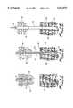
- FIGS. 1A-Fshow a diagrammatic view of a prior art micropile construction sequence
- FIG. 1Ashows insertion of a first casing segment into the ground with part of the casing segment removed for detail
- FIG. 1Bshows three casing segments inserted into the ground to form a casing, with part of each of the casing segments removed for detail;
- FIG. 1Cshows the three casing segments of FIG. 1B inserted into the ground with a drill rod removed;
- FIG. 1Dshows the three casing segments of FIG. 1B with part of each of the casing segments removed for detail and with reinforcements and grout added to the hole and the casing;
- FIG. 1Eshows two of the casing segments of FIG. 1B as partially withdrawn from the hole and with pressurized grout filling the part of the hole from which the casing was removed, with part of each of the casing segments removed for detail;
- FIG. 1Fshows the two casing segments of FIG. 1E, with the top portion of the top casing segment anchored in a concrete footing;
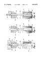
- FIG. 2shows a diagrammatic view of a micropile embodying the present invention
- FIG. 3shows an early assembly stage of the micropile of FIG. 2, with the casing being partially withdrawn from the hole and with grout filling the part of the hole from which the casing was removed, two of the three casing segments still in the hole and a third, temporary casing segment removed from the end of the casing;
- FIG. 4shows a further stage of assembly of the micropile of FIG. 2, with a casing coupler and shortened top casing segment added to the casing;
- FIG. 5shows a further stage of assembly of the micropile of FIG. 2, with a casing coupler pressed into the ground and with a concrete footing cast around the shortened top casing segment;
- FIG. 6shows a second micropile embodying the present invention, the micropile shown as installed in an underlying soil.
- FIG. 2shows a micropile 40 embodying the present invention.
- the micropile 40includes a casing 52, formed from three casing segments 52a, b, d.
- the top end of the casing 52extends into a concrete footing 56.
- the beginning steps for installation of the micropile 40are in accordance with the description relating to FIGS. 1A-D in the Background Section of this disclosure.
- the micropile 40includes a novel shortened top casing segment 52d.
- the shortened top casing segment 52dis attached to the other segments 52a-b of the casing 52 for the micropile 40 by a casing coupler 58.
- the casing coupler 58is located just below the concrete footing 56 of the micropile 40.
- installation of the micropile 40begins by drilling a hole and inserting three casing segments 52a-b in the hole (the third casing segment is not shown, but is similar to the casing segment 14c described in the Background section of this disclosure). It is to be understood that any number of casing segments can be used to extend the casing the necessary depth. However, for simplicity, the casing 52 shown in FIG. 3 is installed with three elongate, hollow, cylindrical casing segments 52a-b attached end-to-end.
- the second casing segment 52bis attached to the first casing segment 52a by threading an external set of threads (not shown, but well known in the art) in the end of the second casing segment 52b onto an internally-threaded end of the first casing segment 52a.
- the second casing segment 52bincludes internal threads (not shown, but well known in the art) at its top end.
- the third casing segment (not shown) of the casing 52also includes external threads that are thread onto the internal threads on the top of the second casing segment 52b.
- each of the segmentscan be by threading segment into segment as described above so as to form casing joints 54.
- each of the casing segments 52a-bmay be provided with external threads on each end, and the connections can be made by casing couplers.
- reinforcements 64such as steel rebar, are placed down the length of the inside of the casing 52.
- the reinforcements 64can occupy as much as one half the internal volume of the casing 52.
- grout 66is introduced into the casing by tremie (not shown, but well known in the art).
- the third casing segmentis then detached from the rest of the casing 52.
- the casing coupler 58(FIG. 4) is threaded onto the end of the second casing segment 52b.
- One end of the shortened top casing segment 52dincludes external threads that are threaded into the internal threads at the opposite end of the casing coupler 58.
- the casing 52is then reinserted into the ground by the drilling equipment (not shown, but well known in the art) until the casing coupler 58 is below the bottom of the level to which the bottom of the concrete footing 56 will extend. (FIG. 5).
- the top end of the shortened top segment 52d of the casing 52extends out of the hole an appropriate amount to anchor the casing within the concrete footing 56.
- the top end of the shortened top casing segment 52dincludes large external threads 68.
- a number of large thread-on steel plates or rings 70are threaded onto the threads 68 on the shortened top casing segment 52d (FIG. 5).
- the steel rings 70are spaced along the length of the threads 68.
- the concrete footing 56is cast into place around the thread-on steel rings 70 and the top end of the casing 52.
- the concrete footing 56is cast such that the casing coupler 58 is located just below the bottom edge of the concrete footing 56.
- the thread-on steel rings 70permit quick and easy final installation of the micropile 40.
- the thread-on steel rings 70can easily be placed on the end of the casing 52 so that the concrete footing 56 may be cast around the rings. No welding of the thread-on steel rings 70 to the casing is required.
- Each of the individual thread-on steel rings 70provides a separate anchor for the casing 52 within the concrete footing 56.
- the micropile 40can also be used for retaining walls and slope stabilization. In these installations, the location of maximum bending stress removed from the concrete footing 56 is located further down into the casing 52. By performing soil fists, the slide plane 80 (FIG. 6) of a soil area may be determined. After this value is determined, an operator of the drill rig installs casing couplers in the joints of the casing that will be adjacent to the slide plane. If casing couplers 58 are required for lower casing joints, they will be installed with the casing 52 as it is drilled into the ground. The renewing structure of the micropile is typically the same as described above, with the top of the casing cast into a concrete cap beam 156.
Landscapes
- Engineering & Computer Science (AREA)
- Structural Engineering (AREA)
- Life Sciences & Earth Sciences (AREA)
- General Life Sciences & Earth Sciences (AREA)
- Mining & Mineral Resources (AREA)
- Paleontology (AREA)
- Civil Engineering (AREA)
- General Engineering & Computer Science (AREA)
- Piles And Underground Anchors (AREA)
Abstract
Description
This invention relates to underground reinforcement of structures and, more specifically, to an improved pile for reinforcing a structure.
A pile is a heavy beam of timber, concrete, or steel that extends into the earth and serves as a foundation or support for a structure. Piles are divided into two general categories: displacement piles and replacement piles. Displacement piles are members that are driven or vibrated into the ground, thereby displacing the surrounding soil laterally during installation. Replacement piles are placed or constructed within a previously drilled hole, thus replacing the excavated ground.
A micropile is a small diameter (typically less than 300 millimeters) replacement pile. Micropiles are used mainly for foundation support of a structure to resist static and seismic loading conditions. Over the last several years, micropiles have become popular for use in commercial buildings and transportation structures. Micropiles are also used as in-situ reinforcements for slope and excavation stability.
Micropiles withstand axial as well as lateral loads and may be considered as a substitute for conventional piles or as one component in a composite soil/pile mass, depending on the design concept employed. Micropiles are installed by methods that cause minimal disturbance to structure, soil, and the environment. The small size of the machinery required for installing micropiles permits installation of micropiles in locations having limited access and low head room. This advantage permits the micropiles to be installed within existing structures.
To form a typical micropile, a hole is drilled, reinforcing steel is placed into the hole, and the hole is filled with mortar, or "grout". The process of filling the hole with the grout is called "grouting". A construction sequence of atypical micropile 10 is shown in FIGS. 1A-F. Installation begins by drilling ahole 12 and inserting acasing 14 in the hole. Thecasing 14 shown in FIGS. 1A-F consists of three elongate, hollow,cylindrical casing segments 14a-c attached end-to-end.
Installation of thecasing 14 occurs simultaneous with the drilling of the hole. This occurs because thefirst casing segment 14a induces cutting teeth (not shown, but well known in the art) at its bottom end. To prepare for drilling, thefirst casing segment 14a attached to a drill rig (not shown, but well known in the art) and is rotated into the ground. In difficult soil conditions, aninternal drill rod 18 with adrill bit 16 on a distal end can be advanced with thecasing 14 to aid in drilling. Thefirst casing segment 14a extends around thedrill rod 18 and abuts against the backside of thedrill bit 16.
Once thefirst casing segment 14a is in place, the drill rig is prepared for drilling. Thefirst casing segment 14a is drilled to a depth that is less than the length of thefirst casing segment 14a (FIG. 1A).
Asecond casing segment 14b is attached to the end of thefirst casing segment 14a by threading an external set of threads in the end of thesecond casing segment 14b into internal threads on the top end of thefirst casing segment 14a. Alternatively, the segments of acasing 14 can be attached to one another by a casing coupler (not shown in FIGS. 1A-F, but well known in the art). A casing coupler is a cylindrical, hollow element with internal threads on opposite ends. If the casing coupler is used, both ends of each of the casing segments will have external threads. The external threads on the top end of the first casing segment are threaded into one end of the casing coupler, and the external threads of an adjacent casing segment are threaded into the opposite end of the casing coupler.
After thesecond casing segment 14b is attached to thefirst casing segment 14a, drilling continues until the top edge of thesecond casing segment 14b is adjacent to the ground. Athird casing segment 14c is attached to the end of thesecond casing segment 14b. This process is continued until thecasing 14 extends completely through the upper, looser portions of the soil base (called the "less competent stratum" and designated generally by thenumeral 20 in FIGS. 1A-F), and into the solid under-soil (called the "bearing stratum" and designated generally by thenumeral 22 in FIGS. 1A-F) (FIG. 1B). Any number of casing may be used to reach the required depth. However, for simplicity, only threecasing segments 14a-c are shown in FIGS. 1A-F.
After thecasing 14 is in place, thedrill rod 18 anddrill bit 16 are pulled out of the casing 14 (FIG. 1C).Reinforcements 24, such as steel rebar, are placed down the length of the inside of the casing. Thereinforcements 24 can occupy as much as one half the internal volume of thecasing 14. After thereinforcements 24 are placed in thecasing 14,grout 26 is introduced into the casing by tremie (not shown, but well known in the art) (FIG. 1D).
After thecasing 14 is filled withgrout 26, thecasing 14 is backed out of the drilledhole 12.Further grout 26 is added under pressure to thecasing 14 while the casing is being withdrawn so that thehole 12 left by thecasing 14 is filled with grout 26 (FIG. 1E). The pressurized grouting and withdrawal of the casing continues until the bottom edge of the casing is adjacent to the top edge of the embedment length in thebearing stratum 22. Casing segments are removed as thecasing 14 is withdrawn from thehole 12. In the sequence shown in FIGS. 1A-F, only thethird casing segment 14c is detached from thecasing 14, and the top end of thesecond casing segment 14b extends out of the ground after grouting is complete. Preferably, the pressure used during the grouting process is adequate so that thegrout 26 is pressed against the inner surface of thehole 12 so as to create a consistent grout/ground bond. The remaining portion of thecasing 14 is left in place through the lesscompetent stratum 20 after the pressurized grouting. After grouting, thecasing 14 is typically reinserted a set distance into the top portion of the pressure grouted length, allowing a structural transition between the upper encased and lower uncased portions of the pile.
Finally, steel plates 28 (FIG. 1F) are welded to the top of thecasing 14. In thecasing 14 shown in FIGS. 1A-F, thesteel plate 28 is welded to the top of thesecond casing segment 14b. Aconcrete footing 30 is cast around thesteel plate 28 and the top end of thecasing 14. Themicropile 10 is now complete.
The structural capacity of themicropile 10 depends largely on the strength of the elements used as thereinforcements 24 and thecasing 14. Thereinforcements 24 and thecasing 14 are typically formed of high transition strength steel, and are designed to resist most or all of the applied load on themicropile 10.
Thereinforcements 24 transfer the load applied to themicropile 10 through the grout to thebearing stratum 22. An effective transfer of the applied load can only occur if themicropile 10 is sufficiently anchored in theconcrete footing 30 and thebearing stratum 22. The drilling and grouting methods used in themicropile 10 installation allow high grout/ground bond values to be generated along the grout/bearing stratum interface, and properly anchor the micropile in thebearing stratum 22.
Anchoring of thereinforcement 24 and thecasing 14 to theconcrete footing 30 is provided primarily by thesteel plates 28. Thus, the welded connection between thecasing 14 and thesteel plates 28 serves a vital function for the anchoring of the casing in theconcrete footing 30. It has been found that welding of thesteel plates 28 to the top end of thecasing 14 decreases the ductility of the high-capacity steel in thecasing 14 in the areas of the casing affected by the heat of the weld. This less ductile, heat-affected steel can cause a premature failure of the casing steel at the attachment to thesteel plates 28. There exists a need for a better structure for anchoring a high strength steel casing to a concrete footing.
During a seismic event (earthquake), lateral movement of thefooting 30 can induce a curvature in the portion of thepile 10 below the footing in the lesscompetent stratum 20. This curvature creates a bending moment and stresses in the pile casing, which are greatest in the length of the casing just below the footing. Lateral displacements which induce bending can also occur in applications where the micropile is used as a component of an earth stabilization system. In these applications, the bending moment is greatest at the slide plane of the micropile. There exists a need for a structure that can reinforce the casing threaded joint where the casing is subject to larger bending stresses.
The present invention provides a pile for connecting a structure to underlying soil. The pile includes a footing connected to the structure, the footing defining a bottom. A casing extends from the footing into underlying soil. The casing includes a plurality of casing segments attached end-to-end. The uppermost casing segment extends into the footing through the bottom of the footing. The pile includes a casing coupler that attaches the uppermost casing segment to an adjacent casing segment. The casing coupler is located substantially outside the footing in the location where bending reinforcement of the joint is required.
In accordance with further aspects of the invention, the uppermost casing segment further includes external threads. A ring is threaded onto the external threads and is anchored in the footing.
In accordance with still further aspects of the invention, a plurality of rings are threaded onto the external threads and are anchored in the footing.
In accordance with yet other aspects of the invention, a pile for connecting a structure to underlying soil is provided. The pile includes a footing connected to the structure, the footing defining a bottom. A casing extends from the footing into underlying soil. The casing includes having a plurality of casing segments attached end-to-end. The uppermost casing segment extends into the footing through the bottom of the footing and includes external threads. A ring is threaded onto the external threads of the uppermost casing segment and is anchored in the footing.
In accordance with yet another aspect of the invention, a method for installing a pile between a structure and an underlying soil is provided. The method includes drilling a hole and installing a casing in the hole from adjacent the structure into underlying soil. The casing includes a plurality of casing segments attached end-to-end. Each of the casing segments, once installed, are located at least partly within the hole. After the casing is installed, a portion of the casing is withdrawn from the hole so that at least one of the casing segments is substantially removed from the hole. The at least one casing segment is then removed from the casing. The casing remaining in the hole and the portion of the hole from which the casing was withdrawn are grouted, and a casing coupler is attached to the end of the casing closest to the structure. An uppermost casing segment is attached to the casing coupler and a footing is casted around the uppermost casing segment and connected to the structure, the footing defining a bottom. The footing is arranged such that the casing coupler is substantially outside the footing and adjacent to the bottom of the footing. Alternatively, the casing coupler is installed with the casing where required by joint strength considerations.
In accordance with still further aspects of the present invention, the uppermost casing segment includes external threads, and the method described above includes threading at least one ring on the external threads of the uppermost casing segment prior to casting the footing. The casting occurs around the at least one ring. The step may further include threading a plurality of rings on the external threads of the uppermost casing segment prior to casting the footing and casting around the plurality of rings.
The foregoing aspects and many of the attendant advantages of this invention will become more readily appreciated as the same becomes better understood by reference to the following detailed description, when taken in conjunction with the accompanying drawings, wherein:
FIGS. 1A-F show a diagrammatic view of a prior art micropile construction sequence;
FIG. 1A shows insertion of a first casing segment into the ground with part of the casing segment removed for detail;
FIG. 1B shows three casing segments inserted into the ground to form a casing, with part of each of the casing segments removed for detail;
FIG. 1C shows the three casing segments of FIG. 1B inserted into the ground with a drill rod removed;
FIG. 1D shows the three casing segments of FIG. 1B with part of each of the casing segments removed for detail and with reinforcements and grout added to the hole and the casing;
FIG. 1E shows two of the casing segments of FIG. 1B as partially withdrawn from the hole and with pressurized grout filling the part of the hole from which the casing was removed, with part of each of the casing segments removed for detail;
FIG. 1F shows the two casing segments of FIG. 1E, with the top portion of the top casing segment anchored in a concrete footing;
FIG. 2 shows a diagrammatic view of a micropile embodying the present invention;
FIG. 3 shows an early assembly stage of the micropile of FIG. 2, with the casing being partially withdrawn from the hole and with grout filling the part of the hole from which the casing was removed, two of the three casing segments still in the hole and a third, temporary casing segment removed from the end of the casing;
FIG. 4 shows a further stage of assembly of the micropile of FIG. 2, with a casing coupler and shortened top casing segment added to the casing;
FIG. 5 shows a further stage of assembly of the micropile of FIG. 2, with a casing coupler pressed into the ground and with a concrete footing cast around the shortened top casing segment; and
FIG. 6 shows a second micropile embodying the present invention, the micropile shown as installed in an underlying soil.
Referring now to the drawing, in which like reference numerals represent like parts throughout the several views, FIG. 2 shows amicropile 40 embodying the present invention. Themicropile 40 includes acasing 52, formed from threecasing segments 52a, b, d. The top end of thecasing 52 extends into aconcrete footing 56.
Briefly described, the beginning steps for installation of themicropile 40 are in accordance with the description relating to FIGS. 1A-D in the Background Section of this disclosure. However, unlike themicropile 10 described in the Background Section of this disclosure, themicropile 40 includes a novel shortenedtop casing segment 52d. The shortenedtop casing segment 52d is attached to theother segments 52a-b of thecasing 52 for themicropile 40 by acasing coupler 58. Thecasing coupler 58 is located just below theconcrete footing 56 of themicropile 40.
As with the micropile 10 described the Background Section of this disclosure, installation of themicropile 40 begins by drilling a hole and inserting threecasing segments 52a-b in the hole (the third casing segment is not shown, but is similar to thecasing segment 14c described in the Background section of this disclosure). It is to be understood that any number of casing segments can be used to extend the casing the necessary depth. However, for simplicity, thecasing 52 shown in FIG. 3 is installed with three elongate, hollow,cylindrical casing segments 52a-b attached end-to-end.
The second casing segment 52b is attached to thefirst casing segment 52a by threading an external set of threads (not shown, but well known in the art) in the end of the second casing segment 52b onto an internally-threaded end of thefirst casing segment 52a. The second casing segment 52b includes internal threads (not shown, but well known in the art) at its top end. The third casing segment (not shown) of thecasing 52 also includes external threads that are thread onto the internal threads on the top of the second casing segment 52b.
As described above, more than three casing segments can be used for thecasing 52. It is preferred that the final length of thecasing 52 be sufficient to extend completely through the lesscompetent stratum 20 and into the bearingstratum 22. The connection of each of the segments can be by threading segment into segment as described above so as to form casing joints 54. Alternatively, each of thecasing segments 52a-b may be provided with external threads on each end, and the connections can be made by casing couplers.
After thecasing segments 52a-c are in place,reinforcements 64, such as steel rebar, are placed down the length of the inside of thecasing 52. Thereinforcements 64 can occupy as much as one half the internal volume of thecasing 52. After thereinforcement 64 is placed in thecasing 14,grout 66 is introduced into the casing by tremie (not shown, but well known in the art).
After thecasing 52 is filled withgrout 66, thecasing 52 is backed out of the drilled hole.Further grout 66 is added under pressure to thecasing 52 while the casing is being withdrawn so that the hole left by the casing is filled with grout 66 (FIG. 3). The pressurized grouting and withdrawal of thecasing 52 continues until the bottom edge of the casing is adjacent to the top edge of the embodiment length in thebearing stratum 20. Casing segments are removed as thecasing 52 is withdrawn from the hole. In the sequence described in this preferred embodiment, only the third casing segment is detached from thecasing 52, and the top end of the second casing segment 52b extends slightly out of the ground after withdrawal of the casing is complete.
The third casing segment is then detached from the rest of thecasing 52. The casing coupler 58 (FIG. 4) is threaded onto the end of the second casing segment 52b. One end of the shortenedtop casing segment 52d includes external threads that are threaded into the internal threads at the opposite end of thecasing coupler 58. Thecasing 52 is then reinserted into the ground by the drilling equipment (not shown, but well known in the art) until thecasing coupler 58 is below the bottom of the level to which the bottom of theconcrete footing 56 will extend. (FIG. 5).
The top end of the shortenedtop segment 52d of thecasing 52 extends out of the hole an appropriate amount to anchor the casing within theconcrete footing 56. The top end of the shortenedtop casing segment 52d includes largeexternal threads 68. A number of large thread-on steel plates or rings 70 are threaded onto thethreads 68 on the shortenedtop casing segment 52d (FIG. 5). The steel rings 70 are spaced along the length of thethreads 68.
After the thread-on steel rings 70 are threaded onto thethreads 68 on the shortenedtop casing segment 52d, theconcrete footing 56 is cast into place around the thread-on steel rings 70 and the top end of thecasing 52. Theconcrete footing 56 is cast such that thecasing coupler 58 is located just below the bottom edge of theconcrete footing 56.
The thread-on steel rings 70 permit quick and easy final installation of themicropile 40. The thread-on steel rings 70 can easily be placed on the end of thecasing 52 so that theconcrete footing 56 may be cast around the rings. No welding of the thread-on steel rings 70 to the casing is required. Each of the individual thread-on steel rings 70 provides a separate anchor for thecasing 52 within theconcrete footing 56.
Locating thecasing coupler 58 just below theconcrete footing 56 and substantially outside the concrete footing reinforces thecasing 52 at the portion of the casing that is subject to maximum bending stress. In this manner, thecasing coupler 58 prevents damage to thecasing 52 at this location.
The micropile 40 can also be used for retaining walls and slope stabilization. In these installations, the location of maximum bending stress removed from theconcrete footing 56 is located further down into thecasing 52. By performing soil fists, the slide plane 80 (FIG. 6) of a soil area may be determined. After this value is determined, an operator of the drill rig installs casing couplers in the joints of the casing that will be adjacent to the slide plane. If casing couplers 58 are required for lower casing joints, they will be installed with thecasing 52 as it is drilled into the ground. The renewing structure of the micropile is typically the same as described above, with the top of the casing cast into aconcrete cap beam 156.
While this invention has been described in detail with particular reference to preferred embodiments thereof, it will be understood that variations and modifications can be effected within the spirit and scope of the invention as described hereinbefore and as defined in the appended claims.
Claims (8)
1. A pile for connecting a structure to underlying soil, the pile comprising:
(a) a footing adapted to connect to the structure, the footing having a bottom surface;
(b) a tubular casing with an upper end and a lower end, the casing upper end being fully embedded within the footing, the casing lower end adapted to being fully embedded in the underlying soil, the casing comprising a plurality of casing segments attached end-to-end, including
(i) a first casing segment having a first end that provides the casing upper end and that includes exterior threads, and having a second end that extends out the footing bottom surface;
(ii) a second casing segment having a first end; and
(iii) a number of remaining casing segments;
(c) a casing coupler mechanically connecting the first casing segment second end with the second casing segment first end via threaded mating surfaces, the casing coupler being located substantially outside the footing and near the bottom surface of the footing; and
(d) at least one ring threaded onto the first casing segment first end, the at least one ring being sized to be fully embedded within the footing effectively anchoring the casing to the footing.
2. The pile of claim 1, where the at least one ring includes a plurality of rings that are threaded onto the external threads and that are each fully anchored and embedded in the footing.
3. The pile of claim 1, wherein the first casing segment second end and the second casing segment first end comprise integral external threads and the casing coupler comprises internal threads for mating with the external threads of the first and second casing segments.
4. The pile of claim 1, wherein the footing is a cap beam.
5. A method for installing a pile between a structure and an underlying soil, comprising:
drilling a hole from adjacent the structure into an underlying soil;
installing a tubular casing in the hole, the casing comprising a plurality of casing segments attached end-to-end, each of the casing segments, once installed, being located at least partly within the hole;
withdrawing a portion of the casing from the hole so that at least one of the casing segments is substantially removed from the hole;
removing the at least one casing segment from the casing to leave the adjacent casing end exposed;
grouting the casing remaining in the hole and the portion of the hole from which the casing was withdrawn, the hole being located below the casing;
attaching a casing coupler to the exposed casing end;
mechanically attaching one end of a first casing segment to the casing coupler via threaded mating surfaces;
attaching at least one ring around the other end of the first casing segment; and
after attaching the at least one ring, casting a footing around the combination of the first casing segment and the attached at least one ring, the footing defining bottom surface, the footing being arranged such that the casing coupler is located substantially outside the footing and adjacent to the bottom surface of the footing, the footing further being arranged such that the at least one ring is fully embedded within the footing.
6. The method of claim 5, wherein the at least one ring is a plurality of rings.
7. The method of claim 5, wherein the first casing segment and the exposed casing segment end comprise integral external threads and the casing coupler comprises internal threads for mating with the external threads of the first and exposed casing segments, and wherein attaching a casing coupler to the end of the casing closest to the structure comprises threading the casing coupler onto the end of the casing, and wherein mechanically attaching the one end of a first casing segment to the casing coupler comprises threading the first casing segment into the casing coupler.
8. The method of claim 5, wherein the footing is a cap beam.
Priority Applications (2)
| Application Number | Priority Date | Filing Date | Title |
|---|---|---|---|
| US08/818,617US6012874A (en) | 1997-03-14 | 1997-03-14 | Micropile casing and method |
| JP07355398AJP4010383B2 (en) | 1997-03-14 | 1998-03-06 | Pile method |
Applications Claiming Priority (1)
| Application Number | Priority Date | Filing Date | Title |
|---|---|---|---|
| US08/818,617US6012874A (en) | 1997-03-14 | 1997-03-14 | Micropile casing and method |
Publications (1)
| Publication Number | Publication Date |
|---|---|
| US6012874Atrue US6012874A (en) | 2000-01-11 |
Family
ID=25225969
Family Applications (1)
| Application Number | Title | Priority Date | Filing Date |
|---|---|---|---|
| US08/818,617Expired - Fee RelatedUS6012874A (en) | 1997-03-14 | 1997-03-14 | Micropile casing and method |
Country Status (2)
| Country | Link |
|---|---|
| US (1) | US6012874A (en) |
| JP (1) | JP4010383B2 (en) |
Cited By (97)
| Publication number | Priority date | Publication date | Assignee | Title |
|---|---|---|---|---|
| US20010047866A1 (en)* | 1998-12-07 | 2001-12-06 | Cook Robert Lance | Wellbore casing |
| US6368021B1 (en)* | 1998-05-16 | 2002-04-09 | Liberty Offshore, Ltd. | Pile and method for installing same |
| US20020040787A1 (en)* | 1998-12-07 | 2002-04-11 | Cook Robert Lance | Forming a wellbore casing while simultaneously drilling a wellbore |
| US20020100595A1 (en)* | 1999-02-26 | 2002-08-01 | Shell Oil Co. | Flow control system for an apparatus for radially expanding tubular members |
| US20030024708A1 (en)* | 1998-12-07 | 2003-02-06 | Shell Oil Co. | Structral support |
| US6543967B1 (en)* | 2002-02-22 | 2003-04-08 | Frederick S. Marshall | Staggered rebar for concrete pilings |
| US6557640B1 (en) | 1998-12-07 | 2003-05-06 | Shell Oil Company | Lubrication and self-cleaning system for expansion mandrel |
| US6575240B1 (en)* | 1998-12-07 | 2003-06-10 | Shell Oil Company | System and method for driving pipe |
| US6575250B1 (en) | 1999-11-15 | 2003-06-10 | Shell Oil Company | Expanding a tubular element in a wellbore |
| US6634431B2 (en) | 1998-11-16 | 2003-10-21 | Robert Lance Cook | Isolation of subterranean zones |
| US6640903B1 (en) | 1998-12-07 | 2003-11-04 | Shell Oil Company | Forming a wellbore casing while simultaneously drilling a wellbore |
| US20030222455A1 (en)* | 1999-04-26 | 2003-12-04 | Shell Oil Co. | Expandable connector |
| US6712154B2 (en) | 1998-11-16 | 2004-03-30 | Enventure Global Technology | Isolation of subterranean zones |
| US6745845B2 (en) | 1998-11-16 | 2004-06-08 | Shell Oil Company | Isolation of subterranean zones |
| US20040115007A1 (en)* | 2002-12-17 | 2004-06-17 | Dewitt Wayne | Method for casting a partially reinforced concrete pile in the ground |
| US20040182569A1 (en)* | 1998-12-07 | 2004-09-23 | Shell Oil Co. | Apparatus for expanding a tubular member |
| US20040231858A1 (en)* | 1999-07-09 | 2004-11-25 | Kevin Waddell | System for lining a wellbore casing |
| US20040231855A1 (en)* | 2001-07-06 | 2004-11-25 | Cook Robert Lance | Liner hanger |
| US6823937B1 (en) | 1998-12-07 | 2004-11-30 | Shell Oil Company | Wellhead |
| US20040238181A1 (en)* | 2001-07-06 | 2004-12-02 | Cook Robert Lance | Liner hanger |
| US20040251034A1 (en)* | 1999-12-03 | 2004-12-16 | Larry Kendziora | Mono-diameter wellbore casing |
| US20050028988A1 (en)* | 1998-11-16 | 2005-02-10 | Cook Robert Lance | Radial expansion of tubular members |
| US20050045324A1 (en)* | 1998-11-16 | 2005-03-03 | Cook Robert Lance | Radial expansion of tubular members |
| US20050056434A1 (en)* | 2001-11-12 | 2005-03-17 | Watson Brock Wayne | Collapsible expansion cone |
| US20050087337A1 (en)* | 2000-09-18 | 2005-04-28 | Shell Oil Company | Liner hanger with sliding sleeve valve |
| US20050138790A1 (en)* | 2000-10-02 | 2005-06-30 | Cook Robert L. | Method and apparatus for forming a mono-diameter wellbore casing |
| US20050150098A1 (en)* | 2003-06-13 | 2005-07-14 | Robert Lance Cook | Method and apparatus for forming a mono-diameter wellbore casing |
| US20050173108A1 (en)* | 2002-07-29 | 2005-08-11 | Cook Robert L. | Method of forming a mono diameter wellbore casing |
| US20050217866A1 (en)* | 2002-05-06 | 2005-10-06 | Watson Brock W | Mono diameter wellbore casing |
| US20050217865A1 (en)* | 2002-05-29 | 2005-10-06 | Lev Ring | System for radially expanding a tubular member |
| US20050230123A1 (en)* | 2001-12-27 | 2005-10-20 | Waddell Kevin K | Seal receptacle using expandable liner hanger |
| US20050230124A1 (en)* | 1998-12-07 | 2005-10-20 | Cook Robert L | Mono-diameter wellbore casing |
| US20050236163A1 (en)* | 2001-01-17 | 2005-10-27 | Cook Robert L | Mono-diameter wellbore casing |
| US20050236159A1 (en)* | 2002-09-20 | 2005-10-27 | Scott Costa | Threaded connection for expandable tubulars |
| US20050247453A1 (en)* | 2002-08-23 | 2005-11-10 | Mark Shuster | Magnetic impulse applied sleeve method of forming a wellbore casing |
| US20050269107A1 (en)* | 1999-12-03 | 2005-12-08 | Cook Robert L | Mono-diameter wellbore casing |
| US20060032640A1 (en)* | 2002-04-15 | 2006-02-16 | Todd Mattingly Haynes And Boone, L.L.P. | Protective sleeve for threaded connections for expandable liner hanger |
| US20060048948A1 (en)* | 1998-12-07 | 2006-03-09 | Enventure Global Technology, Llc | Anchor hangers |
| US20060054330A1 (en)* | 2002-09-20 | 2006-03-16 | Lev Ring | Mono diameter wellbore casing |
| US20060065406A1 (en)* | 2002-08-23 | 2006-03-30 | Mark Shuster | Interposed joint sealing layer method of forming a wellbore casing |
| US20060065403A1 (en)* | 2002-09-20 | 2006-03-30 | Watson Brock W | Bottom plug for forming a mono diameter wellbore casing |
| US20060090902A1 (en)* | 2002-04-12 | 2006-05-04 | Scott Costa | Protective sleeve for threaded connections for expandable liner hanger |
| US20060096762A1 (en)* | 2002-06-10 | 2006-05-11 | Brisco David P | Mono-diameter wellbore casing |
| US7048067B1 (en) | 1999-11-01 | 2006-05-23 | Shell Oil Company | Wellbore casing repair |
| US20060108123A1 (en)* | 2002-12-05 | 2006-05-25 | Frank De Lucia | System for radially expanding tubular members |
| US20060113085A1 (en)* | 2002-07-24 | 2006-06-01 | Scott Costa | Dual well completion system |
| US20060113086A1 (en)* | 2002-09-20 | 2006-06-01 | Scott Costa | Protective sleeve for expandable tubulars |
| US20060112768A1 (en)* | 2002-09-20 | 2006-06-01 | Mark Shuster | Pipe formability evaluation for expandable tubulars |
| US7055608B2 (en) | 1999-03-11 | 2006-06-06 | Shell Oil Company | Forming a wellbore casing while simultaneously drilling a wellbore |
| US20060169460A1 (en)* | 2003-02-26 | 2006-08-03 | Brisco David P | Apparatus for radially expanding and plastically deforming a tubular member |
| US7100684B2 (en) | 2000-07-28 | 2006-09-05 | Enventure Global Technology | Liner hanger with standoffs |
| US20060208488A1 (en)* | 2003-02-18 | 2006-09-21 | Enventure Global Technology | Protective compression and tension sleeves for threaded connections for radially expandable tubular members |
| US20060207760A1 (en)* | 2002-06-12 | 2006-09-21 | Watson Brock W | Collapsible expansion cone |
| US20060225892A1 (en)* | 2003-03-11 | 2006-10-12 | Enventure Global Technology | Apparatus for radially expanding and plastically deforming a tubular member |
| US7121352B2 (en) | 1998-11-16 | 2006-10-17 | Enventure Global Technology | Isolation of subterranean zones |
| US7172024B2 (en) | 2000-10-02 | 2007-02-06 | Shell Oil Company | Mono-diameter wellbore casing |
| US20070039742A1 (en)* | 2004-02-17 | 2007-02-22 | Enventure Global Technology, Llc | Method and apparatus for coupling expandable tubular members |
| US20070051520A1 (en)* | 1998-12-07 | 2007-03-08 | Enventure Global Technology, Llc | Expansion system |
| US20070056743A1 (en)* | 2003-09-02 | 2007-03-15 | Enventure Global Technology | Method of radially expanding and plastically deforming tubular members |
| US7195064B2 (en) | 1998-12-07 | 2007-03-27 | Enventure Global Technology | Mono-diameter wellbore casing |
| US20070143987A1 (en)* | 2000-10-02 | 2007-06-28 | Shell Oil Company | Method and Apparatus for Forming a Mono-Diameter Wellbore Casing |
| US7258168B2 (en) | 2001-07-27 | 2007-08-21 | Enventure Global Technology L.L.C. | Liner hanger with slip joint sealing members and method of use |
| CN100350105C (en)* | 2005-09-28 | 2007-11-21 | 河北建设勘察研究院有限公司 | Vibrating piling-hammer sink-pull steel protective-cylinder piling method and special steel protective cylinder |
| US7363984B2 (en) | 1998-12-07 | 2008-04-29 | Enventure Global Technology, Llc | System for radially expanding a tubular member |
| US20080135252A1 (en)* | 2001-09-07 | 2008-06-12 | Shell Oil Company | Adjustable Expansion Cone Assembly |
| EP1985765A1 (en) | 2007-04-25 | 2008-10-29 | Jean-Marie Renovation | Device and method for installing a helical foundation micro-pile |
| US7503393B2 (en) | 2003-01-27 | 2009-03-17 | Enventure Global Technology, Inc. | Lubrication system for radially expanding tubular members |
| US7571774B2 (en) | 2002-09-20 | 2009-08-11 | Eventure Global Technology | Self-lubricating expansion mandrel for expandable tubular |
| US7603758B2 (en) | 1998-12-07 | 2009-10-20 | Shell Oil Company | Method of coupling a tubular member |
| US7712522B2 (en) | 2003-09-05 | 2010-05-11 | Enventure Global Technology, Llc | Expansion cone and system |
| US7775290B2 (en) | 2003-04-17 | 2010-08-17 | Enventure Global Technology, Llc | Apparatus for radially expanding and plastically deforming a tubular member |
| US7819185B2 (en) | 2004-08-13 | 2010-10-26 | Enventure Global Technology, Llc | Expandable tubular |
| US7886831B2 (en) | 2003-01-22 | 2011-02-15 | Enventure Global Technology, L.L.C. | Apparatus for radially expanding and plastically deforming a tubular member |
| US20110042142A1 (en)* | 2009-08-18 | 2011-02-24 | Crux Subsurface, Inc. | Spindrill |
| KR101080923B1 (en) | 2011-05-17 | 2011-11-08 | 이장희 | Fixing structure and fixing method of micro pile |
| ITRM20100521A1 (en)* | 2010-10-05 | 2012-04-06 | Giampaolo Capaldini | SEISMIC INSULATION SYSTEM AND METHOD OF REALIZATION. |
| CN102704480A (en)* | 2012-06-03 | 2012-10-03 | 中交第四公路工程局有限公司 | Construction method of front-end vibrating steel casing for super-thick quicksand layer of pile foundation |
| US8511021B2 (en) | 2010-04-16 | 2013-08-20 | Crux Subsurface, Inc. | Structural cap with composite sleeves |
| US20130255667A1 (en)* | 2012-04-02 | 2013-10-03 | Colorado School Of Mines | Solid particle thermal energy storage design for a fluidized-bed concentrating solar power plant |
| US20140161539A1 (en)* | 2012-12-07 | 2014-06-12 | Anoop Kumar Arya | Soil anchor footing |
| EP2789748A1 (en)* | 2013-04-12 | 2014-10-15 | Raccordi Regonesi S.r.L. | Micropile for foundations |
| JP2015055106A (en)* | 2013-09-12 | 2015-03-23 | 株式会社大林組 | Underground structure, and method of reconstructing building structure with underground skeleton |
| US20150218770A1 (en)* | 2014-02-06 | 2015-08-06 | Haydar Arslan | Systems and Methods for Reducing Scouring |
| ES2552588A1 (en)* | 2014-05-29 | 2015-11-30 | 2Pe Pilotes, S.L. | Device for the anchoring of a deep support for a foundation and procedure for said anchoring (Machine-translation by Google Translate, not legally binding) |
| JP2016135971A (en)* | 2015-01-23 | 2016-07-28 | 株式会社フジタ | Joint member of casing segment used in micro pile method |
| JP2016160582A (en)* | 2015-02-27 | 2016-09-05 | 株式会社フジタ | Micropile method and spacer for reinforcing material used in micropile method |
| US9702348B2 (en) | 2013-04-03 | 2017-07-11 | Alliance For Sustainable Energy, Llc | Chemical looping fluidized-bed concentrating solar power system and method |
| US9828739B2 (en) | 2015-11-04 | 2017-11-28 | Crux Subsurface, Inc. | In-line battered composite foundations |
| US9845678B2 (en)* | 2015-05-08 | 2017-12-19 | Normet International Ltd. | Locally anchored self-drilling hollow rock bolt |
| JP2018115548A (en)* | 2018-03-20 | 2018-07-26 | 株式会社フジタ | Casing segment extension method and connection structure in the micropile method |
| US20190003142A1 (en)* | 2017-06-28 | 2019-01-03 | H&K Group, Inc. | Block Retaining Wall with Micro-Pile Soldier Piles |
| US20190177944A1 (en)* | 2018-02-20 | 2019-06-13 | Petram Technologies, Inc. | In-situ Piling and Anchor Shaping using Plasma Blasting |
| US20190218742A1 (en)* | 2018-01-16 | 2019-07-18 | Geopier Foundation Company, Inc. | Soil Reinforcement System Including Angled Soil Reinforcement Elements To Resist Seismic Shear Forces And Methods Of Making Same |
| US10844702B2 (en)* | 2018-03-20 | 2020-11-24 | Petram Technologies, Inc. | Precision utility mapping and excavating using plasma blasting |
| US11203400B1 (en) | 2021-06-17 | 2021-12-21 | General Technologies Corp. | Support system having shaped pile-anchor foundations and a method of forming same |
| US11453992B2 (en)* | 2018-04-26 | 2022-09-27 | Beijing Hengxiang Hongye Foundation Reinforcement Technology Co., Ltd. | Pile foundation bearing platform settlement, reinforcement, lift-up and leveling structure, and construction method thereof |
| US20250179754A1 (en)* | 2022-01-05 | 2025-06-05 | Indian Institute Of Technology Roorkee | Bioinspired skirted footing and its method of installation |
Families Citing this family (4)
| Publication number | Priority date | Publication date | Assignee | Title |
|---|---|---|---|---|
| KR101230014B1 (en) | 2012-11-09 | 2013-02-05 | 주식회사 성지엔지니어링 | The ground reinforcement apparatus |
| JP6071125B2 (en)* | 2013-01-24 | 2017-02-01 | 株式会社ケー・エフ・シー | Underground support joint structure |
| JP6359320B2 (en)* | 2014-04-16 | 2018-07-18 | 株式会社フジタ | Casing segment connection structure in the micropile method |
| JP7081940B2 (en)* | 2018-02-27 | 2022-06-07 | 株式会社フジタ | Micro pile method using a gap blocker |
Citations (9)
| Publication number | Priority date | Publication date | Assignee | Title |
|---|---|---|---|---|
| US582744A (en)* | 1897-05-18 | jarrett | ||
| US760754A (en)* | 1904-02-20 | 1904-05-24 | Samuel Worthington Mcmunn | Sectional shell. |
| US1588516A (en)* | 1923-03-31 | 1926-06-15 | Barnes Albert Fenton | Concrete piling |
| US3354657A (en)* | 1965-05-03 | 1967-11-28 | Lee A Turzillo | Method for installing anchoring or supporting columns in situ |
| US3757528A (en)* | 1971-09-21 | 1973-09-11 | Dyckerhoff & Widmann Ag | Method for producing a bearing pile of reinforced concrete |
| US4254597A (en)* | 1979-08-15 | 1981-03-10 | Allied Surveyor Supplies Manufacturing Co. | Sectionalized driven rod |
| US4610571A (en)* | 1985-10-15 | 1986-09-09 | Braman, Dow And Company | Foundation system and pile coupling for use therein |
| US4668119A (en)* | 1984-06-29 | 1987-05-26 | Innse Innocenti Santeustacchio S.P.A. | Coupling for connecting metal tubes end-to-end, particularly in marine pilings |
| US4832535A (en)* | 1984-12-07 | 1989-05-23 | Michel Crambes | Process for compaction-reinforcement-grouting or for decompaction-drainage and for construction of linear works and plane works in the soils |
Family Cites Families (4)
| Publication number | Priority date | Publication date | Assignee | Title |
|---|---|---|---|---|
| JPS6119047U (en)* | 1984-07-11 | 1986-02-04 | 旭化成株式会社 | Pile cap connection device |
| JPH0718157B2 (en)* | 1986-03-14 | 1995-03-01 | 旭化成工業株式会社 | Piling method |
| JP3020187B2 (en)* | 1992-02-19 | 2000-03-15 | 三谷セキサン株式会社 | Embedded pile method and concrete pile |
| JPH08100432A (en)* | 1994-09-30 | 1996-04-16 | Giken Seisakusho Co Ltd | Footing device |
- 1997
- 1997-03-14USUS08/818,617patent/US6012874A/ennot_activeExpired - Fee Related
- 1998
- 1998-03-06JPJP07355398Apatent/JP4010383B2/ennot_activeExpired - Lifetime
Patent Citations (9)
| Publication number | Priority date | Publication date | Assignee | Title |
|---|---|---|---|---|
| US582744A (en)* | 1897-05-18 | jarrett | ||
| US760754A (en)* | 1904-02-20 | 1904-05-24 | Samuel Worthington Mcmunn | Sectional shell. |
| US1588516A (en)* | 1923-03-31 | 1926-06-15 | Barnes Albert Fenton | Concrete piling |
| US3354657A (en)* | 1965-05-03 | 1967-11-28 | Lee A Turzillo | Method for installing anchoring or supporting columns in situ |
| US3757528A (en)* | 1971-09-21 | 1973-09-11 | Dyckerhoff & Widmann Ag | Method for producing a bearing pile of reinforced concrete |
| US4254597A (en)* | 1979-08-15 | 1981-03-10 | Allied Surveyor Supplies Manufacturing Co. | Sectionalized driven rod |
| US4668119A (en)* | 1984-06-29 | 1987-05-26 | Innse Innocenti Santeustacchio S.P.A. | Coupling for connecting metal tubes end-to-end, particularly in marine pilings |
| US4832535A (en)* | 1984-12-07 | 1989-05-23 | Michel Crambes | Process for compaction-reinforcement-grouting or for decompaction-drainage and for construction of linear works and plane works in the soils |
| US4610571A (en)* | 1985-10-15 | 1986-09-09 | Braman, Dow And Company | Foundation system and pile coupling for use therein |
Cited By (218)
| Publication number | Priority date | Publication date | Assignee | Title |
|---|---|---|---|---|
| US6536993B2 (en) | 1998-05-16 | 2003-03-25 | Liberty Offshore, Ltd. | Pile and method for installing same |
| US6368021B1 (en)* | 1998-05-16 | 2002-04-09 | Liberty Offshore, Ltd. | Pile and method for installing same |
| US7299881B2 (en) | 1998-11-16 | 2007-11-27 | Shell Oil Company | Radial expansion of tubular members |
| US7108072B2 (en) | 1998-11-16 | 2006-09-19 | Shell Oil Company | Lubrication and self-cleaning system for expansion mandrel |
| US7357190B2 (en) | 1998-11-16 | 2008-04-15 | Shell Oil Company | Radial expansion of tubular members |
| US20050077051A1 (en)* | 1998-11-16 | 2005-04-14 | Cook Robert Lance | Radial expansion of tubular members |
| US20050045341A1 (en)* | 1998-11-16 | 2005-03-03 | Cook Robert Lance | Radial expansion of tubular members |
| US7168499B2 (en) | 1998-11-16 | 2007-01-30 | Shell Oil Company | Radial expansion of tubular members |
| US6634431B2 (en) | 1998-11-16 | 2003-10-21 | Robert Lance Cook | Isolation of subterranean zones |
| US20050045324A1 (en)* | 1998-11-16 | 2005-03-03 | Cook Robert Lance | Radial expansion of tubular members |
| US20050028988A1 (en)* | 1998-11-16 | 2005-02-10 | Cook Robert Lance | Radial expansion of tubular members |
| US7121352B2 (en) | 1998-11-16 | 2006-10-17 | Enventure Global Technology | Isolation of subterranean zones |
| US7231985B2 (en) | 1998-11-16 | 2007-06-19 | Shell Oil Company | Radial expansion of tubular members |
| US7246667B2 (en) | 1998-11-16 | 2007-07-24 | Shell Oil Company | Radial expansion of tubular members |
| US7270188B2 (en) | 1998-11-16 | 2007-09-18 | Shell Oil Company | Radial expansion of tubular members |
| US20030173090A1 (en)* | 1998-11-16 | 2003-09-18 | Shell Oil Co. | Lubrication and self-cleaning system for expansion mandrel |
| US7275601B2 (en) | 1998-11-16 | 2007-10-02 | Shell Oil Company | Radial expansion of tubular members |
| US6745845B2 (en) | 1998-11-16 | 2004-06-08 | Shell Oil Company | Isolation of subterranean zones |
| US6712154B2 (en) | 1998-11-16 | 2004-03-30 | Enventure Global Technology | Isolation of subterranean zones |
| US6823937B1 (en) | 1998-12-07 | 2004-11-30 | Shell Oil Company | Wellhead |
| US7195061B2 (en) | 1998-12-07 | 2007-03-27 | Shell Oil Company | Apparatus for expanding a tubular member |
| US20080087418A1 (en)* | 1998-12-07 | 2008-04-17 | Shell Oil Company | Pipeline |
| US7048062B2 (en) | 1998-12-07 | 2006-05-23 | Shell Oil Company | Method of selecting tubular members |
| US7044218B2 (en) | 1998-12-07 | 2006-05-16 | Shell Oil Company | Apparatus for radially expanding tubular members |
| US7363984B2 (en) | 1998-12-07 | 2008-04-29 | Enventure Global Technology, Llc | System for radially expanding a tubular member |
| US6725919B2 (en) | 1998-12-07 | 2004-04-27 | Shell Oil Company | Forming a wellbore casing while simultaneously drilling a wellbore |
| US6739392B2 (en) | 1998-12-07 | 2004-05-25 | Shell Oil Company | Forming a wellbore casing while simultaneously drilling a wellbore |
| US6631760B2 (en) | 1998-12-07 | 2003-10-14 | Shell Oil Company | Tie back liner for a well system |
| US7108061B2 (en) | 1998-12-07 | 2006-09-19 | Shell Oil Company | Expander for a tapered liner with a shoe |
| US6758278B2 (en) | 1998-12-07 | 2004-07-06 | Shell Oil Company | Forming a wellbore casing while simultaneously drilling a wellbore |
| US7350564B2 (en) | 1998-12-07 | 2008-04-01 | Enventure Global Technology, L.L.C. | Mono-diameter wellbore casing |
| US20040182569A1 (en)* | 1998-12-07 | 2004-09-23 | Shell Oil Co. | Apparatus for expanding a tubular member |
| US6575240B1 (en)* | 1998-12-07 | 2003-06-10 | Shell Oil Company | System and method for driving pipe |
| US7240729B2 (en) | 1998-12-07 | 2007-07-10 | Shell Oil Company | Apparatus for expanding a tubular member |
| US7011161B2 (en) | 1998-12-07 | 2006-03-14 | Shell Oil Company | Structural support |
| US7240728B2 (en) | 1998-12-07 | 2007-07-10 | Shell Oil Company | Expandable tubulars with a radial passage and wall portions with different wall thicknesses |
| US20030098154A1 (en)* | 1998-12-07 | 2003-05-29 | Shell Oil Co. | Apparatus for radially expanding tubular members |
| US6561227B2 (en) | 1998-12-07 | 2003-05-13 | Shell Oil Company | Wellbore casing |
| US7419009B2 (en) | 1998-12-07 | 2008-09-02 | Shell Oil Company | Apparatus for radially expanding and plastically deforming a tubular member |
| US6557640B1 (en) | 1998-12-07 | 2003-05-06 | Shell Oil Company | Lubrication and self-cleaning system for expansion mandrel |
| US20030024708A1 (en)* | 1998-12-07 | 2003-02-06 | Shell Oil Co. | Structral support |
| US7216701B2 (en) | 1998-12-07 | 2007-05-15 | Shell Oil Company | Apparatus for expanding a tubular member |
| US7198100B2 (en) | 1998-12-07 | 2007-04-03 | Shell Oil Company | Apparatus for expanding a tubular member |
| US6497289B1 (en) | 1998-12-07 | 2002-12-24 | Robert Lance Cook | Method of creating a casing in a borehole |
| US6640903B1 (en) | 1998-12-07 | 2003-11-04 | Shell Oil Company | Forming a wellbore casing while simultaneously drilling a wellbore |
| US6892819B2 (en) | 1998-12-07 | 2005-05-17 | Shell Oil Company | Forming a wellbore casing while simultaneously drilling a wellbore |
| US7195064B2 (en) | 1998-12-07 | 2007-03-27 | Enventure Global Technology | Mono-diameter wellbore casing |
| US6470966B2 (en) | 1998-12-07 | 2002-10-29 | Robert Lance Cook | Apparatus for forming wellbore casing |
| US20070051520A1 (en)* | 1998-12-07 | 2007-03-08 | Enventure Global Technology, Llc | Expansion system |
| US7665532B2 (en) | 1998-12-07 | 2010-02-23 | Shell Oil Company | Pipeline |
| US7357188B1 (en) | 1998-12-07 | 2008-04-15 | Shell Oil Company | Mono-diameter wellbore casing |
| US7603758B2 (en) | 1998-12-07 | 2009-10-20 | Shell Oil Company | Method of coupling a tubular member |
| US7077211B2 (en) | 1998-12-07 | 2006-07-18 | Shell Oil Company | Method of creating a casing in a borehole |
| US20050205253A1 (en)* | 1998-12-07 | 2005-09-22 | Shell Oil Co. | Apparatus for expanding a tubular member |
| US20010047866A1 (en)* | 1998-12-07 | 2001-12-06 | Cook Robert Lance | Wellbore casing |
| US7174964B2 (en) | 1998-12-07 | 2007-02-13 | Shell Oil Company | Wellhead with radially expanded tubulars |
| US20050224225A1 (en)* | 1998-12-07 | 2005-10-13 | Shell Oil Co. | Apparatus for expanding a tubular member |
| US20050230102A1 (en)* | 1998-12-07 | 2005-10-20 | Shell Oil Co. | Apparatus for expanding a tubular member |
| US20020040787A1 (en)* | 1998-12-07 | 2002-04-11 | Cook Robert Lance | Forming a wellbore casing while simultaneously drilling a wellbore |
| US20050230124A1 (en)* | 1998-12-07 | 2005-10-20 | Cook Robert L | Mono-diameter wellbore casing |
| US20050230103A1 (en)* | 1998-12-07 | 2005-10-20 | Shell Oil Co. | Apparatus for expanding a tubular member |
| US20070012456A1 (en)* | 1998-12-07 | 2007-01-18 | Shell Oil Company | Wellbore Casing |
| US7036582B2 (en) | 1998-12-07 | 2006-05-02 | Shell Oil Company | Expansion cone for radially expanding tubular members |
| US7552776B2 (en) | 1998-12-07 | 2009-06-30 | Enventure Global Technology, Llc | Anchor hangers |
| US7434618B2 (en) | 1998-12-07 | 2008-10-14 | Shell Oil Company | Apparatus for expanding a tubular member |
| US7121337B2 (en) | 1998-12-07 | 2006-10-17 | Shell Oil Company | Apparatus for expanding a tubular member |
| US7077213B2 (en) | 1998-12-07 | 2006-07-18 | Shell Oil Company | Expansion cone for radially expanding tubular members |
| US7159665B2 (en) | 1998-12-07 | 2007-01-09 | Shell Oil Company | Wellbore casing |
| US7147053B2 (en) | 1998-12-07 | 2006-12-12 | Shell Oil Company | Wellhead |
| US20060048948A1 (en)* | 1998-12-07 | 2006-03-09 | Enventure Global Technology, Llc | Anchor hangers |
| US7159667B2 (en) | 1999-02-25 | 2007-01-09 | Shell Oil Company | Method of coupling a tubular member to a preexisting structure |
| US20050183863A1 (en)* | 1999-02-25 | 2005-08-25 | Shell Oil Co. | Method of coupling a tubular member to a preexisting structure |
| US6705395B2 (en) | 1999-02-26 | 2004-03-16 | Shell Oil Company | Wellbore casing |
| US6568471B1 (en) | 1999-02-26 | 2003-05-27 | Shell Oil Company | Liner hanger |
| US7556092B2 (en) | 1999-02-26 | 2009-07-07 | Enventure Global Technology, Llc | Flow control system for an apparatus for radially expanding tubular members |
| US20020100595A1 (en)* | 1999-02-26 | 2002-08-01 | Shell Oil Co. | Flow control system for an apparatus for radially expanding tubular members |
| US7040396B2 (en) | 1999-02-26 | 2006-05-09 | Shell Oil Company | Apparatus for releasably coupling two elements |
| US6857473B2 (en) | 1999-02-26 | 2005-02-22 | Shell Oil Company | Method of coupling a tubular member to a preexisting structure |
| US7044221B2 (en) | 1999-02-26 | 2006-05-16 | Shell Oil Company | Apparatus for coupling a tubular member to a preexisting structure |
| US7063142B2 (en) | 1999-02-26 | 2006-06-20 | Shell Oil Company | Method of applying an axial force to an expansion cone |
| US6966370B2 (en) | 1999-02-26 | 2005-11-22 | Shell Oil Company | Apparatus for actuating an annular piston |
| US20060213668A1 (en)* | 1999-02-26 | 2006-09-28 | Enventure Global Technology | A Method of Coupling Tubular Member |
| US6684947B2 (en) | 1999-02-26 | 2004-02-03 | Shell Oil Company | Apparatus for radially expanding a tubular member |
| US6631759B2 (en) | 1999-02-26 | 2003-10-14 | Shell Oil Company | Apparatus for radially expanding a tubular member |
| US6631769B2 (en) | 1999-02-26 | 2003-10-14 | Shell Oil Company | Method of operating an apparatus for radially expanding a tubular member |
| US7055608B2 (en) | 1999-03-11 | 2006-06-06 | Shell Oil Company | Forming a wellbore casing while simultaneously drilling a wellbore |
| US7438132B2 (en) | 1999-03-11 | 2008-10-21 | Shell Oil Company | Concentric pipes expanded at the pipe ends and method of forming |
| US20030222455A1 (en)* | 1999-04-26 | 2003-12-04 | Shell Oil Co. | Expandable connector |
| US6968618B2 (en) | 1999-04-26 | 2005-11-29 | Shell Oil Company | Expandable connector |
| US20040231858A1 (en)* | 1999-07-09 | 2004-11-25 | Kevin Waddell | System for lining a wellbore casing |
| US7350563B2 (en) | 1999-07-09 | 2008-04-01 | Enventure Global Technology, L.L.C. | System for lining a wellbore casing |
| US7048067B1 (en) | 1999-11-01 | 2006-05-23 | Shell Oil Company | Wellbore casing repair |
| US6575250B1 (en) | 1999-11-15 | 2003-06-10 | Shell Oil Company | Expanding a tubular element in a wellbore |
| US7234531B2 (en) | 1999-12-03 | 2007-06-26 | Enventure Global Technology, Llc | Mono-diameter wellbore casing |
| US20040251034A1 (en)* | 1999-12-03 | 2004-12-16 | Larry Kendziora | Mono-diameter wellbore casing |
| US20050269107A1 (en)* | 1999-12-03 | 2005-12-08 | Cook Robert L | Mono-diameter wellbore casing |
| US7516790B2 (en) | 1999-12-03 | 2009-04-14 | Enventure Global Technology, Llc | Mono-diameter wellbore casing |
| US7100684B2 (en) | 2000-07-28 | 2006-09-05 | Enventure Global Technology | Liner hanger with standoffs |
| US6976541B2 (en) | 2000-09-18 | 2005-12-20 | Shell Oil Company | Liner hanger with sliding sleeve valve |
| US20050087337A1 (en)* | 2000-09-18 | 2005-04-28 | Shell Oil Company | Liner hanger with sliding sleeve valve |
| US7172021B2 (en) | 2000-09-18 | 2007-02-06 | Shell Oil Company | Liner hanger with sliding sleeve valve |
| US20070143987A1 (en)* | 2000-10-02 | 2007-06-28 | Shell Oil Company | Method and Apparatus for Forming a Mono-Diameter Wellbore Casing |
| US7201223B2 (en) | 2000-10-02 | 2007-04-10 | Shell Oil Company | Method and apparatus for forming a mono-diameter wellbore casing |
| US7100685B2 (en) | 2000-10-02 | 2006-09-05 | Enventure Global Technology | Mono-diameter wellbore casing |
| US7325602B2 (en) | 2000-10-02 | 2008-02-05 | Shell Oil Company | Method and apparatus for forming a mono-diameter wellbore casing |
| US7363690B2 (en) | 2000-10-02 | 2008-04-29 | Shell Oil Company | Method and apparatus for forming a mono-diameter wellbore casing |
| US7363691B2 (en) | 2000-10-02 | 2008-04-29 | Shell Oil Company | Method and apparatus for forming a mono-diameter wellbore casing |
| US7204007B2 (en) | 2000-10-02 | 2007-04-17 | Shell Oil Company | Method and apparatus for forming a mono-diameter wellbore casing |
| US7172024B2 (en) | 2000-10-02 | 2007-02-06 | Shell Oil Company | Mono-diameter wellbore casing |
| US7146702B2 (en) | 2000-10-02 | 2006-12-12 | Shell Oil Company | Method and apparatus for forming a mono-diameter wellbore casing |
| US7172019B2 (en) | 2000-10-02 | 2007-02-06 | Shell Oil Company | Method and apparatus for forming a mono-diameter wellbore casing |
| US20050138790A1 (en)* | 2000-10-02 | 2005-06-30 | Cook Robert L. | Method and apparatus for forming a mono-diameter wellbore casing |
| US20050150660A1 (en)* | 2000-10-02 | 2005-07-14 | Cook Robert L. | Method and apparatus for forming a mono-diameter wellbore casing |
| US20050144771A1 (en)* | 2000-10-02 | 2005-07-07 | Cook Robert L. | Method and apparatus for forming a mono-diameter wellbore casing |
| US20050144772A1 (en)* | 2000-10-02 | 2005-07-07 | Cook Robert L. | Method and apparatus for forming a mono-diameter wellbore casing |
| US7410000B2 (en) | 2001-01-17 | 2008-08-12 | Enventure Global Technology, Llc. | Mono-diameter wellbore casing |
| US20050236163A1 (en)* | 2001-01-17 | 2005-10-27 | Cook Robert L | Mono-diameter wellbore casing |
| US20040238181A1 (en)* | 2001-07-06 | 2004-12-02 | Cook Robert Lance | Liner hanger |
| US7290616B2 (en) | 2001-07-06 | 2007-11-06 | Enventure Global Technology, L.L.C. | Liner hanger |
| US7168496B2 (en) | 2001-07-06 | 2007-01-30 | Eventure Global Technology | Liner hanger |
| US20040231855A1 (en)* | 2001-07-06 | 2004-11-25 | Cook Robert Lance | Liner hanger |
| US7258168B2 (en) | 2001-07-27 | 2007-08-21 | Enventure Global Technology L.L.C. | Liner hanger with slip joint sealing members and method of use |
| US7416027B2 (en) | 2001-09-07 | 2008-08-26 | Enventure Global Technology, Llc | Adjustable expansion cone assembly |
| US20080135252A1 (en)* | 2001-09-07 | 2008-06-12 | Shell Oil Company | Adjustable Expansion Cone Assembly |
| US20050056434A1 (en)* | 2001-11-12 | 2005-03-17 | Watson Brock Wayne | Collapsible expansion cone |
| US7559365B2 (en) | 2001-11-12 | 2009-07-14 | Enventure Global Technology, Llc | Collapsible expansion cone |
| US7383889B2 (en) | 2001-11-12 | 2008-06-10 | Enventure Global Technology, Llc | Mono diameter wellbore casing |
| US20050056433A1 (en)* | 2001-11-12 | 2005-03-17 | Lev Ring | Mono diameter wellbore casing |
| US20050230123A1 (en)* | 2001-12-27 | 2005-10-20 | Waddell Kevin K | Seal receptacle using expandable liner hanger |
| US7290605B2 (en) | 2001-12-27 | 2007-11-06 | Enventure Global Technology | Seal receptacle using expandable liner hanger |
| US6543967B1 (en)* | 2002-02-22 | 2003-04-08 | Frederick S. Marshall | Staggered rebar for concrete pilings |
| US20060090902A1 (en)* | 2002-04-12 | 2006-05-04 | Scott Costa | Protective sleeve for threaded connections for expandable liner hanger |
| US7740076B2 (en) | 2002-04-12 | 2010-06-22 | Enventure Global Technology, L.L.C. | Protective sleeve for threaded connections for expandable liner hanger |
| US7918284B2 (en) | 2002-04-15 | 2011-04-05 | Enventure Global Technology, L.L.C. | Protective sleeve for threaded connections for expandable liner hanger |
| US20060032640A1 (en)* | 2002-04-15 | 2006-02-16 | Todd Mattingly Haynes And Boone, L.L.P. | Protective sleeve for threaded connections for expandable liner hanger |
| US20050217866A1 (en)* | 2002-05-06 | 2005-10-06 | Watson Brock W | Mono diameter wellbore casing |
| US20050217865A1 (en)* | 2002-05-29 | 2005-10-06 | Lev Ring | System for radially expanding a tubular member |
| US7360591B2 (en) | 2002-05-29 | 2008-04-22 | Enventure Global Technology, Llc | System for radially expanding a tubular member |
| US20060096762A1 (en)* | 2002-06-10 | 2006-05-11 | Brisco David P | Mono-diameter wellbore casing |
| US7398832B2 (en) | 2002-06-10 | 2008-07-15 | Enventure Global Technology, Llc | Mono-diameter wellbore casing |
| US20060207760A1 (en)* | 2002-06-12 | 2006-09-21 | Watson Brock W | Collapsible expansion cone |
| US20060113085A1 (en)* | 2002-07-24 | 2006-06-01 | Scott Costa | Dual well completion system |
| US20050173108A1 (en)* | 2002-07-29 | 2005-08-11 | Cook Robert L. | Method of forming a mono diameter wellbore casing |
| US7377326B2 (en) | 2002-08-23 | 2008-05-27 | Enventure Global Technology, L.L.C. | Magnetic impulse applied sleeve method of forming a wellbore casing |
| US20050247453A1 (en)* | 2002-08-23 | 2005-11-10 | Mark Shuster | Magnetic impulse applied sleeve method of forming a wellbore casing |
| US20060065406A1 (en)* | 2002-08-23 | 2006-03-30 | Mark Shuster | Interposed joint sealing layer method of forming a wellbore casing |
| US7424918B2 (en) | 2002-08-23 | 2008-09-16 | Enventure Global Technology, L.L.C. | Interposed joint sealing layer method of forming a wellbore casing |
| US20060054330A1 (en)* | 2002-09-20 | 2006-03-16 | Lev Ring | Mono diameter wellbore casing |
| US7571774B2 (en) | 2002-09-20 | 2009-08-11 | Eventure Global Technology | Self-lubricating expansion mandrel for expandable tubular |
| US20060113086A1 (en)* | 2002-09-20 | 2006-06-01 | Scott Costa | Protective sleeve for expandable tubulars |
| US20060112768A1 (en)* | 2002-09-20 | 2006-06-01 | Mark Shuster | Pipe formability evaluation for expandable tubulars |
| US7404444B2 (en) | 2002-09-20 | 2008-07-29 | Enventure Global Technology | Protective sleeve for expandable tubulars |
| US7739917B2 (en) | 2002-09-20 | 2010-06-22 | Enventure Global Technology, Llc | Pipe formability evaluation for expandable tubulars |
| US20050236159A1 (en)* | 2002-09-20 | 2005-10-27 | Scott Costa | Threaded connection for expandable tubulars |
| US7513313B2 (en) | 2002-09-20 | 2009-04-07 | Enventure Global Technology, Llc | Bottom plug for forming a mono diameter wellbore casing |
| US20060065403A1 (en)* | 2002-09-20 | 2006-03-30 | Watson Brock W | Bottom plug for forming a mono diameter wellbore casing |
| US20060108123A1 (en)* | 2002-12-05 | 2006-05-25 | Frank De Lucia | System for radially expanding tubular members |
| US20070246934A1 (en)* | 2002-12-10 | 2007-10-25 | Enventure Global Technology | Protective compression and tension sleeves for threaded connections for radially expandable tubular members |
| US20040115007A1 (en)* | 2002-12-17 | 2004-06-17 | Dewitt Wayne | Method for casting a partially reinforced concrete pile in the ground |
| US6773208B2 (en)* | 2002-12-17 | 2004-08-10 | Dewitt Wayne | Method for casting a partially reinforced concrete pile in the ground |
| US7886831B2 (en) | 2003-01-22 | 2011-02-15 | Enventure Global Technology, L.L.C. | Apparatus for radially expanding and plastically deforming a tubular member |
| US7503393B2 (en) | 2003-01-27 | 2009-03-17 | Enventure Global Technology, Inc. | Lubrication system for radially expanding tubular members |
| US20090038138A1 (en)* | 2003-02-18 | 2009-02-12 | Enventure Global Technology | Protective compression and tension sleeves for threaded connections for radially expandable tubular members |
| US20070278788A1 (en)* | 2003-02-18 | 2007-12-06 | Enventure Global Technology | Protective compression and tension sleeves for threaded connections for radially expandable tubular members |
| US20060208488A1 (en)* | 2003-02-18 | 2006-09-21 | Enventure Global Technology | Protective compression and tension sleeves for threaded connections for radially expandable tubular members |
| US7438133B2 (en) | 2003-02-26 | 2008-10-21 | Enventure Global Technology, Llc | Apparatus and method for radially expanding and plastically deforming a tubular member |
| US20060169460A1 (en)* | 2003-02-26 | 2006-08-03 | Brisco David P | Apparatus for radially expanding and plastically deforming a tubular member |
| US20060225892A1 (en)* | 2003-03-11 | 2006-10-12 | Enventure Global Technology | Apparatus for radially expanding and plastically deforming a tubular member |
| US7793721B2 (en) | 2003-03-11 | 2010-09-14 | Eventure Global Technology, Llc | Apparatus for radially expanding and plastically deforming a tubular member |
| US7775290B2 (en) | 2003-04-17 | 2010-08-17 | Enventure Global Technology, Llc | Apparatus for radially expanding and plastically deforming a tubular member |
| US7308755B2 (en) | 2003-06-13 | 2007-12-18 | Shell Oil Company | Apparatus for forming a mono-diameter wellbore casing |
| US20050150098A1 (en)* | 2003-06-13 | 2005-07-14 | Robert Lance Cook | Method and apparatus for forming a mono-diameter wellbore casing |
| US20070056743A1 (en)* | 2003-09-02 | 2007-03-15 | Enventure Global Technology | Method of radially expanding and plastically deforming tubular members |
| US7712522B2 (en) | 2003-09-05 | 2010-05-11 | Enventure Global Technology, Llc | Expansion cone and system |
| US20070039742A1 (en)* | 2004-02-17 | 2007-02-22 | Enventure Global Technology, Llc | Method and apparatus for coupling expandable tubular members |
| US7819185B2 (en) | 2004-08-13 | 2010-10-26 | Enventure Global Technology, Llc | Expandable tubular |
| CN100350105C (en)* | 2005-09-28 | 2007-11-21 | 河北建设勘察研究院有限公司 | Vibrating piling-hammer sink-pull steel protective-cylinder piling method and special steel protective cylinder |
| EP1985765A1 (en) | 2007-04-25 | 2008-10-29 | Jean-Marie Renovation | Device and method for installing a helical foundation micro-pile |
| US8511020B2 (en) | 2009-08-18 | 2013-08-20 | Crux Subsurface, Inc. | Composite cap |
| US20110044766A1 (en)* | 2009-08-18 | 2011-02-24 | Crux Subsurface, Inc. | Micropile Foundation Matrix |
| US20110044768A1 (en)* | 2009-08-18 | 2011-02-24 | Crux Subsurface, Inc. | Batter Angled Flange Composite Cap |
| US8974150B2 (en)* | 2009-08-18 | 2015-03-10 | Crux Subsurface, Inc. | Micropile foundation matrix |
| US20110042142A1 (en)* | 2009-08-18 | 2011-02-24 | Crux Subsurface, Inc. | Spindrill |
| US8602123B2 (en) | 2009-08-18 | 2013-12-10 | Crux Subsurface, Inc. | Spindrill |
| US8631618B2 (en) | 2009-08-18 | 2014-01-21 | Crux Subsurface, Inc. | Batter angled flange composite cap |
| US9290901B2 (en)* | 2009-08-18 | 2016-03-22 | Crux Subsurface, Inc. | Micropile foundation matrix |
| US8511021B2 (en) | 2010-04-16 | 2013-08-20 | Crux Subsurface, Inc. | Structural cap with composite sleeves |
| ITRM20100521A1 (en)* | 2010-10-05 | 2012-04-06 | Giampaolo Capaldini | SEISMIC INSULATION SYSTEM AND METHOD OF REALIZATION. |
| KR101080923B1 (en) | 2011-05-17 | 2011-11-08 | 이장희 | Fixing structure and fixing method of micro pile |
| US9783949B2 (en) | 2012-01-31 | 2017-10-10 | Anoop Kumar Arya | Soil anchor footing |
| US20130255667A1 (en)* | 2012-04-02 | 2013-10-03 | Colorado School Of Mines | Solid particle thermal energy storage design for a fluidized-bed concentrating solar power plant |
| CN102704480A (en)* | 2012-06-03 | 2012-10-03 | 中交第四公路工程局有限公司 | Construction method of front-end vibrating steel casing for super-thick quicksand layer of pile foundation |
| CN102704480B (en)* | 2012-06-03 | 2014-06-04 | 中交第四公路工程局有限公司 | Construction method for treating pile foundation ultra-thick quicksand layer by using front-end vibration steel casing |
| US20140161539A1 (en)* | 2012-12-07 | 2014-06-12 | Anoop Kumar Arya | Soil anchor footing |
| US9328474B2 (en)* | 2012-12-07 | 2016-05-03 | Anoop Kumar Arya | Soil anchor footing |
| US9702348B2 (en) | 2013-04-03 | 2017-07-11 | Alliance For Sustainable Energy, Llc | Chemical looping fluidized-bed concentrating solar power system and method |
| EP2789748A1 (en)* | 2013-04-12 | 2014-10-15 | Raccordi Regonesi S.r.L. | Micropile for foundations |
| JP2015055106A (en)* | 2013-09-12 | 2015-03-23 | 株式会社大林組 | Underground structure, and method of reconstructing building structure with underground skeleton |
| US20150218770A1 (en)* | 2014-02-06 | 2015-08-06 | Haydar Arslan | Systems and Methods for Reducing Scouring |
| AU2015214574B2 (en)* | 2014-02-06 | 2017-06-08 | Exxonmobil Upstream Research Company | Systems and methods for reducing scouring |
| US10844565B2 (en)* | 2014-02-06 | 2020-11-24 | Exxonmobil Upstream Research Company | Systems and methods for reducing scouring |
| ES2552588A1 (en)* | 2014-05-29 | 2015-11-30 | 2Pe Pilotes, S.L. | Device for the anchoring of a deep support for a foundation and procedure for said anchoring (Machine-translation by Google Translate, not legally binding) |
| JP2016135971A (en)* | 2015-01-23 | 2016-07-28 | 株式会社フジタ | Joint member of casing segment used in micro pile method |
| JP2016160582A (en)* | 2015-02-27 | 2016-09-05 | 株式会社フジタ | Micropile method and spacer for reinforcing material used in micropile method |
| US9845678B2 (en)* | 2015-05-08 | 2017-12-19 | Normet International Ltd. | Locally anchored self-drilling hollow rock bolt |
| US9828739B2 (en) | 2015-11-04 | 2017-11-28 | Crux Subsurface, Inc. | In-line battered composite foundations |
| US20190003142A1 (en)* | 2017-06-28 | 2019-01-03 | H&K Group, Inc. | Block Retaining Wall with Micro-Pile Soldier Piles |
| US20190218742A1 (en)* | 2018-01-16 | 2019-07-18 | Geopier Foundation Company, Inc. | Soil Reinforcement System Including Angled Soil Reinforcement Elements To Resist Seismic Shear Forces And Methods Of Making Same |
| US20190177944A1 (en)* | 2018-02-20 | 2019-06-13 | Petram Technologies, Inc. | In-situ Piling and Anchor Shaping using Plasma Blasting |
| US10577767B2 (en)* | 2018-02-20 | 2020-03-03 | Petram Technologies, Inc. | In-situ piling and anchor shaping using plasma blasting |
| US20200190761A1 (en)* | 2018-02-20 | 2020-06-18 | Petram Technologies, Inc. | In-situ Piling and Anchor Shaping using Plasma Blasting |
| US10760239B2 (en)* | 2018-02-20 | 2020-09-01 | Petram Technologies, Inc. | In-situ piling and anchor shaping using plasma blasting |
| US10844702B2 (en)* | 2018-03-20 | 2020-11-24 | Petram Technologies, Inc. | Precision utility mapping and excavating using plasma blasting |
| JP2018115548A (en)* | 2018-03-20 | 2018-07-26 | 株式会社フジタ | Casing segment extension method and connection structure in the micropile method |
| US11453992B2 (en)* | 2018-04-26 | 2022-09-27 | Beijing Hengxiang Hongye Foundation Reinforcement Technology Co., Ltd. | Pile foundation bearing platform settlement, reinforcement, lift-up and leveling structure, and construction method thereof |
| US11203400B1 (en) | 2021-06-17 | 2021-12-21 | General Technologies Corp. | Support system having shaped pile-anchor foundations and a method of forming same |
| US11427288B1 (en) | 2021-06-17 | 2022-08-30 | General Technologies Corp. | Support system having shaped pile-anchor foundations and a method of forming same |
| US20250179754A1 (en)* | 2022-01-05 | 2025-06-05 | Indian Institute Of Technology Roorkee | Bioinspired skirted footing and its method of installation |
Also Published As
| Publication number | Publication date |
|---|---|
| JPH1171752A (en) | 1999-03-16 |
| JP4010383B2 (en) | 2007-11-21 |
Similar Documents
| Publication | Publication Date | Title |
|---|---|---|
| US6012874A (en) | Micropile casing and method | |
| KR101671123B1 (en) | Tunnel construction method by using pre-support and post-support, and suitable device therefor | |
| US6652195B2 (en) | Method and apparatus for forming piles in place | |
| US6665990B1 (en) | High-tension high-compression foundation for tower structures | |
| US3987636A (en) | Methods and apparatus for anchoring a submerged structure to a waterbed | |
| KR20170061061A (en) | Tunnel construction method by using pre-support and post-support, and suitable device therefor | |
| KR20170061060A (en) | Tunnel construction method by using pre-support and post-support, and suitable device therefor | |
| JP2011236705A (en) | Foundation structure of structure and method of constructing the same | |
| CN100580193C (en) | The basic structure of the tower | |
| US7857549B1 (en) | Underpinning pile assembly for supporting a structure upon the earth and process for installing such underpinning pile assembly | |
| KR20130029906A (en) | An expanding device of frictional force | |
| JP3385876B2 (en) | Cast-in-place pile construction method just below the existing foundation | |
| JPH08184037A (en) | Double pipe type steel pipe pile | |
| CN111997618B (en) | Anti-seismic supporting structure of mine shaft | |
| EP1046753B1 (en) | Method and apparatus for forming piles in place | |
| KR20090049132A (en) | Ground reinforcement device and ground reinforcement method using the same | |
| KR100400853B1 (en) | Removable soil nailing method and its nail assembly | |
| JP4684479B2 (en) | Structure of the connection between the pile and the pile head structure | |
| KR101398687B1 (en) | Micro pile with improved end bearing capacity and its construction methods thereof | |
| JP4724879B2 (en) | Foundation pile structure | |
| CA2264197C (en) | Method and apparatus for forming piles in place | |
| KR102781771B1 (en) | the improved connector, the slope reinforcement structure and method using the same | |
| JP3851581B2 (en) | Ground strength reinforcement structure of the ground | |
| KR102578665B1 (en) | Concrete Reinforcing Method Using Reaction Anchor | |
| KR102552929B1 (en) | Structure and method for anchorage of pile head with improved anchoring strength and base reinforcement |
Legal Events
| Date | Code | Title | Description |
|---|---|---|---|
| AS | Assignment | Owner name:FUJITA RESEARCH, CALIFORNIA Free format text:ASSIGNMENT OF ASSIGNORS INTEREST;ASSIGNORS:GRONECK, PAUL B.;ARMOUR, THOMAS A.;REEL/FRAME:009722/0601 Effective date:19971202 Owner name:DBM CONTRACTORS, INC., WASHINGTON Free format text:ASSIGNMENT OF ASSIGNORS INTEREST;ASSIGNORS:GRONECK, PAUL B.;ARMOUR, THOMAS A.;REEL/FRAME:009722/0601 Effective date:19971202 Owner name:ECO GEOSYSTEMS, INC., PENNSYLVANIA Free format text:ASSIGNMENT OF ASSIGNORS INTEREST;ASSIGNORS:GRONECK, PAUL B.;ARMOUR, THOMAS A.;REEL/FRAME:009722/0601 Effective date:19971202 | |
| CC | Certificate of correction | ||
| FPAY | Fee payment | Year of fee payment:4 | |
| REMI | Maintenance fee reminder mailed | ||
| LAPS | Lapse for failure to pay maintenance fees | ||
| STCH | Information on status: patent discontinuation | Free format text:PATENT EXPIRED DUE TO NONPAYMENT OF MAINTENANCE FEES UNDER 37 CFR 1.362 | |
| FP | Expired due to failure to pay maintenance fee | Effective date:20080111 |