US6012453A - Apparatus for withdrawal of liquid from a container and method - Google Patents
Apparatus for withdrawal of liquid from a container and methodDownload PDFInfo
- Publication number
- US6012453A US6012453AUS08/951,138US95113897AUS6012453AUS 6012453 AUS6012453 AUS 6012453AUS 95113897 AUS95113897 AUS 95113897AUS 6012453 AUS6012453 AUS 6012453A
- Authority
- US
- United States
- Prior art keywords
- liquid
- container
- conduit
- pick
- open end
- Prior art date
- Legal status (The legal status is an assumption and is not a legal conclusion. Google has not performed a legal analysis and makes no representation as to the accuracy of the status listed.)
- Expired - Lifetime
Links
Images


Classifications
- A—HUMAN NECESSITIES
- A62—LIFE-SAVING; FIRE-FIGHTING
- A62B—DEVICES, APPARATUS OR METHODS FOR LIFE-SAVING
- A62B7/00—Respiratory apparatus
- A62B7/06—Respiratory apparatus with liquid oxygen or air; Cryogenic systems
- A—HUMAN NECESSITIES
- A62—LIFE-SAVING; FIRE-FIGHTING
- A62B—DEVICES, APPARATUS OR METHODS FOR LIFE-SAVING
- A62B7/00—Respiratory apparatus
- A62B7/02—Respiratory apparatus with compressed oxygen or air
- F—MECHANICAL ENGINEERING; LIGHTING; HEATING; WEAPONS; BLASTING
- F17—STORING OR DISTRIBUTING GASES OR LIQUIDS
- F17C—VESSELS FOR CONTAINING OR STORING COMPRESSED, LIQUEFIED OR SOLIDIFIED GASES; FIXED-CAPACITY GAS-HOLDERS; FILLING VESSELS WITH, OR DISCHARGING FROM VESSELS, COMPRESSED, LIQUEFIED, OR SOLIDIFIED GASES
- F17C7/00—Methods or apparatus for discharging liquefied, solidified, or compressed gases from pressure vessels, not covered by another subclass
- F17C7/02—Discharging liquefied gases
- F17C7/04—Discharging liquefied gases with change of state, e.g. vaporisation
- F—MECHANICAL ENGINEERING; LIGHTING; HEATING; WEAPONS; BLASTING
- F17—STORING OR DISTRIBUTING GASES OR LIQUIDS
- F17C—VESSELS FOR CONTAINING OR STORING COMPRESSED, LIQUEFIED OR SOLIDIFIED GASES; FIXED-CAPACITY GAS-HOLDERS; FILLING VESSELS WITH, OR DISCHARGING FROM VESSELS, COMPRESSED, LIQUEFIED, OR SOLIDIFIED GASES
- F17C9/00—Methods or apparatus for discharging liquefied or solidified gases from vessels not under pressure
- F17C9/02—Methods or apparatus for discharging liquefied or solidified gases from vessels not under pressure with change of state, e.g. vaporisation
- B—PERFORMING OPERATIONS; TRANSPORTING
- B63—SHIPS OR OTHER WATERBORNE VESSELS; RELATED EQUIPMENT
- B63C—LAUNCHING, HAULING-OUT, OR DRY-DOCKING OF VESSELS; LIFE-SAVING IN WATER; EQUIPMENT FOR DWELLING OR WORKING UNDER WATER; MEANS FOR SALVAGING OR SEARCHING FOR UNDERWATER OBJECTS
- B63C11/00—Equipment for dwelling or working underwater; Means for searching for underwater objects
- B63C11/02—Divers' equipment
- B63C11/18—Air supply
- B63C11/22—Air supply carried by diver
- B63C2011/2263—Air supply carried by diver using breathing gas stored in its liquid phase, e.g. cryogenic breathing gas
- F—MECHANICAL ENGINEERING; LIGHTING; HEATING; WEAPONS; BLASTING
- F17—STORING OR DISTRIBUTING GASES OR LIQUIDS
- F17C—VESSELS FOR CONTAINING OR STORING COMPRESSED, LIQUEFIED OR SOLIDIFIED GASES; FIXED-CAPACITY GAS-HOLDERS; FILLING VESSELS WITH, OR DISCHARGING FROM VESSELS, COMPRESSED, LIQUEFIED, OR SOLIDIFIED GASES
- F17C2201/00—Vessel construction, in particular geometry, arrangement or size
- F17C2201/01—Shape
- F17C2201/0104—Shape cylindrical
- F17C2201/0109—Shape cylindrical with exteriorly curved end-piece
- F—MECHANICAL ENGINEERING; LIGHTING; HEATING; WEAPONS; BLASTING
- F17—STORING OR DISTRIBUTING GASES OR LIQUIDS
- F17C—VESSELS FOR CONTAINING OR STORING COMPRESSED, LIQUEFIED OR SOLIDIFIED GASES; FIXED-CAPACITY GAS-HOLDERS; FILLING VESSELS WITH, OR DISCHARGING FROM VESSELS, COMPRESSED, LIQUEFIED, OR SOLIDIFIED GASES
- F17C2201/00—Vessel construction, in particular geometry, arrangement or size
- F17C2201/05—Size
- F17C2201/056—Small (<1 m3)
- F—MECHANICAL ENGINEERING; LIGHTING; HEATING; WEAPONS; BLASTING
- F17—STORING OR DISTRIBUTING GASES OR LIQUIDS
- F17C—VESSELS FOR CONTAINING OR STORING COMPRESSED, LIQUEFIED OR SOLIDIFIED GASES; FIXED-CAPACITY GAS-HOLDERS; FILLING VESSELS WITH, OR DISCHARGING FROM VESSELS, COMPRESSED, LIQUEFIED, OR SOLIDIFIED GASES
- F17C2203/00—Vessel construction, in particular walls or details thereof
- F17C2203/03—Thermal insulations
- F17C2203/0391—Thermal insulations by vacuum
- F—MECHANICAL ENGINEERING; LIGHTING; HEATING; WEAPONS; BLASTING
- F17—STORING OR DISTRIBUTING GASES OR LIQUIDS
- F17C—VESSELS FOR CONTAINING OR STORING COMPRESSED, LIQUEFIED OR SOLIDIFIED GASES; FIXED-CAPACITY GAS-HOLDERS; FILLING VESSELS WITH, OR DISCHARGING FROM VESSELS, COMPRESSED, LIQUEFIED, OR SOLIDIFIED GASES
- F17C2205/00—Vessel construction, in particular mounting arrangements, attachments or identifications means
- F17C2205/01—Mounting arrangements
- F17C2205/0123—Mounting arrangements characterised by number of vessels
- F17C2205/013—Two or more vessels
- F—MECHANICAL ENGINEERING; LIGHTING; HEATING; WEAPONS; BLASTING
- F17—STORING OR DISTRIBUTING GASES OR LIQUIDS
- F17C—VESSELS FOR CONTAINING OR STORING COMPRESSED, LIQUEFIED OR SOLIDIFIED GASES; FIXED-CAPACITY GAS-HOLDERS; FILLING VESSELS WITH, OR DISCHARGING FROM VESSELS, COMPRESSED, LIQUEFIED, OR SOLIDIFIED GASES
- F17C2205/00—Vessel construction, in particular mounting arrangements, attachments or identifications means
- F17C2205/03—Fluid connections, filters, valves, closure means or other attachments
- F17C2205/0302—Fittings, valves, filters, or components in connection with the gas storage device
- F17C2205/0323—Valves
- F17C2205/0332—Safety valves or pressure relief valves
- F—MECHANICAL ENGINEERING; LIGHTING; HEATING; WEAPONS; BLASTING
- F17—STORING OR DISTRIBUTING GASES OR LIQUIDS
- F17C—VESSELS FOR CONTAINING OR STORING COMPRESSED, LIQUEFIED OR SOLIDIFIED GASES; FIXED-CAPACITY GAS-HOLDERS; FILLING VESSELS WITH, OR DISCHARGING FROM VESSELS, COMPRESSED, LIQUEFIED, OR SOLIDIFIED GASES
- F17C2205/00—Vessel construction, in particular mounting arrangements, attachments or identifications means
- F17C2205/03—Fluid connections, filters, valves, closure means or other attachments
- F17C2205/0302—Fittings, valves, filters, or components in connection with the gas storage device
- F17C2205/0338—Pressure regulators
- F—MECHANICAL ENGINEERING; LIGHTING; HEATING; WEAPONS; BLASTING
- F17—STORING OR DISTRIBUTING GASES OR LIQUIDS
- F17C—VESSELS FOR CONTAINING OR STORING COMPRESSED, LIQUEFIED OR SOLIDIFIED GASES; FIXED-CAPACITY GAS-HOLDERS; FILLING VESSELS WITH, OR DISCHARGING FROM VESSELS, COMPRESSED, LIQUEFIED, OR SOLIDIFIED GASES
- F17C2205/00—Vessel construction, in particular mounting arrangements, attachments or identifications means
- F17C2205/03—Fluid connections, filters, valves, closure means or other attachments
- F17C2205/0302—Fittings, valves, filters, or components in connection with the gas storage device
- F17C2205/0382—Constructional details of valves, regulators
- F17C2205/0385—Constructional details of valves, regulators in blocks or units
- F—MECHANICAL ENGINEERING; LIGHTING; HEATING; WEAPONS; BLASTING
- F17—STORING OR DISTRIBUTING GASES OR LIQUIDS
- F17C—VESSELS FOR CONTAINING OR STORING COMPRESSED, LIQUEFIED OR SOLIDIFIED GASES; FIXED-CAPACITY GAS-HOLDERS; FILLING VESSELS WITH, OR DISCHARGING FROM VESSELS, COMPRESSED, LIQUEFIED, OR SOLIDIFIED GASES
- F17C2205/00—Vessel construction, in particular mounting arrangements, attachments or identifications means
- F17C2205/03—Fluid connections, filters, valves, closure means or other attachments
- F17C2205/0388—Arrangement of valves, regulators, filters
- F17C2205/0391—Arrangement of valves, regulators, filters inside the pressure vessel
- F—MECHANICAL ENGINEERING; LIGHTING; HEATING; WEAPONS; BLASTING
- F17—STORING OR DISTRIBUTING GASES OR LIQUIDS
- F17C—VESSELS FOR CONTAINING OR STORING COMPRESSED, LIQUEFIED OR SOLIDIFIED GASES; FIXED-CAPACITY GAS-HOLDERS; FILLING VESSELS WITH, OR DISCHARGING FROM VESSELS, COMPRESSED, LIQUEFIED, OR SOLIDIFIED GASES
- F17C2205/00—Vessel construction, in particular mounting arrangements, attachments or identifications means
- F17C2205/03—Fluid connections, filters, valves, closure means or other attachments
- F17C2205/0388—Arrangement of valves, regulators, filters
- F17C2205/0394—Arrangement of valves, regulators, filters in direct contact with the pressure vessel
- F17C2205/0397—Arrangement of valves, regulators, filters in direct contact with the pressure vessel on both sides of the pressure vessel
- F—MECHANICAL ENGINEERING; LIGHTING; HEATING; WEAPONS; BLASTING
- F17—STORING OR DISTRIBUTING GASES OR LIQUIDS
- F17C—VESSELS FOR CONTAINING OR STORING COMPRESSED, LIQUEFIED OR SOLIDIFIED GASES; FIXED-CAPACITY GAS-HOLDERS; FILLING VESSELS WITH, OR DISCHARGING FROM VESSELS, COMPRESSED, LIQUEFIED, OR SOLIDIFIED GASES
- F17C2221/00—Handled fluid, in particular type of fluid
- F17C2221/01—Pure fluids
- F17C2221/011—Oxygen
- F—MECHANICAL ENGINEERING; LIGHTING; HEATING; WEAPONS; BLASTING
- F17—STORING OR DISTRIBUTING GASES OR LIQUIDS
- F17C—VESSELS FOR CONTAINING OR STORING COMPRESSED, LIQUEFIED OR SOLIDIFIED GASES; FIXED-CAPACITY GAS-HOLDERS; FILLING VESSELS WITH, OR DISCHARGING FROM VESSELS, COMPRESSED, LIQUEFIED, OR SOLIDIFIED GASES
- F17C2221/00—Handled fluid, in particular type of fluid
- F17C2221/01—Pure fluids
- F17C2221/014—Nitrogen
- F—MECHANICAL ENGINEERING; LIGHTING; HEATING; WEAPONS; BLASTING
- F17—STORING OR DISTRIBUTING GASES OR LIQUIDS
- F17C—VESSELS FOR CONTAINING OR STORING COMPRESSED, LIQUEFIED OR SOLIDIFIED GASES; FIXED-CAPACITY GAS-HOLDERS; FILLING VESSELS WITH, OR DISCHARGING FROM VESSELS, COMPRESSED, LIQUEFIED, OR SOLIDIFIED GASES
- F17C2223/00—Handled fluid before transfer, i.e. state of fluid when stored in the vessel or before transfer from the vessel
- F17C2223/01—Handled fluid before transfer, i.e. state of fluid when stored in the vessel or before transfer from the vessel characterised by the phase
- F17C2223/0146—Two-phase
- F17C2223/0153—Liquefied gas, e.g. LPG, GPL
- F17C2223/0161—Liquefied gas, e.g. LPG, GPL cryogenic, e.g. LNG, GNL, PLNG
- F—MECHANICAL ENGINEERING; LIGHTING; HEATING; WEAPONS; BLASTING
- F17—STORING OR DISTRIBUTING GASES OR LIQUIDS
- F17C—VESSELS FOR CONTAINING OR STORING COMPRESSED, LIQUEFIED OR SOLIDIFIED GASES; FIXED-CAPACITY GAS-HOLDERS; FILLING VESSELS WITH, OR DISCHARGING FROM VESSELS, COMPRESSED, LIQUEFIED, OR SOLIDIFIED GASES
- F17C2223/00—Handled fluid before transfer, i.e. state of fluid when stored in the vessel or before transfer from the vessel
- F17C2223/03—Handled fluid before transfer, i.e. state of fluid when stored in the vessel or before transfer from the vessel characterised by the pressure level
- F17C2223/033—Small pressure, e.g. for liquefied gas
- F—MECHANICAL ENGINEERING; LIGHTING; HEATING; WEAPONS; BLASTING
- F17—STORING OR DISTRIBUTING GASES OR LIQUIDS
- F17C—VESSELS FOR CONTAINING OR STORING COMPRESSED, LIQUEFIED OR SOLIDIFIED GASES; FIXED-CAPACITY GAS-HOLDERS; FILLING VESSELS WITH, OR DISCHARGING FROM VESSELS, COMPRESSED, LIQUEFIED, OR SOLIDIFIED GASES
- F17C2223/00—Handled fluid before transfer, i.e. state of fluid when stored in the vessel or before transfer from the vessel
- F17C2223/04—Handled fluid before transfer, i.e. state of fluid when stored in the vessel or before transfer from the vessel characterised by other properties of handled fluid before transfer
- F17C2223/042—Localisation of the removal point
- F17C2223/046—Localisation of the removal point in the liquid
- F17C2223/047—Localisation of the removal point in the liquid with a dip tube
- F—MECHANICAL ENGINEERING; LIGHTING; HEATING; WEAPONS; BLASTING
- F17—STORING OR DISTRIBUTING GASES OR LIQUIDS
- F17C—VESSELS FOR CONTAINING OR STORING COMPRESSED, LIQUEFIED OR SOLIDIFIED GASES; FIXED-CAPACITY GAS-HOLDERS; FILLING VESSELS WITH, OR DISCHARGING FROM VESSELS, COMPRESSED, LIQUEFIED, OR SOLIDIFIED GASES
- F17C2227/00—Transfer of fluids, i.e. method or means for transferring the fluid; Heat exchange with the fluid
- F17C2227/03—Heat exchange with the fluid
- F17C2227/0302—Heat exchange with the fluid by heating
- F—MECHANICAL ENGINEERING; LIGHTING; HEATING; WEAPONS; BLASTING
- F17—STORING OR DISTRIBUTING GASES OR LIQUIDS
- F17C—VESSELS FOR CONTAINING OR STORING COMPRESSED, LIQUEFIED OR SOLIDIFIED GASES; FIXED-CAPACITY GAS-HOLDERS; FILLING VESSELS WITH, OR DISCHARGING FROM VESSELS, COMPRESSED, LIQUEFIED, OR SOLIDIFIED GASES
- F17C2250/00—Accessories; Control means; Indicating, measuring or monitoring of parameters
- F17C2250/04—Indicating or measuring of parameters as input values
- F17C2250/0404—Parameters indicated or measured
- F17C2250/0408—Level of content in the vessel
- F17C2250/0413—Level of content in the vessel with floats
- F—MECHANICAL ENGINEERING; LIGHTING; HEATING; WEAPONS; BLASTING
- F17—STORING OR DISTRIBUTING GASES OR LIQUIDS
- F17C—VESSELS FOR CONTAINING OR STORING COMPRESSED, LIQUEFIED OR SOLIDIFIED GASES; FIXED-CAPACITY GAS-HOLDERS; FILLING VESSELS WITH, OR DISCHARGING FROM VESSELS, COMPRESSED, LIQUEFIED, OR SOLIDIFIED GASES
- F17C2270/00—Applications
- F17C2270/02—Applications for medical applications
- F17C2270/025—Breathing
- F—MECHANICAL ENGINEERING; LIGHTING; HEATING; WEAPONS; BLASTING
- F17—STORING OR DISTRIBUTING GASES OR LIQUIDS
- F17C—VESSELS FOR CONTAINING OR STORING COMPRESSED, LIQUEFIED OR SOLIDIFIED GASES; FIXED-CAPACITY GAS-HOLDERS; FILLING VESSELS WITH, OR DISCHARGING FROM VESSELS, COMPRESSED, LIQUEFIED, OR SOLIDIFIED GASES
- F17C2270/00—Applications
- F17C2270/05—Applications for industrial use
- F17C2270/0509—"Dewar" vessels
- Y—GENERAL TAGGING OF NEW TECHNOLOGICAL DEVELOPMENTS; GENERAL TAGGING OF CROSS-SECTIONAL TECHNOLOGIES SPANNING OVER SEVERAL SECTIONS OF THE IPC; TECHNICAL SUBJECTS COVERED BY FORMER USPC CROSS-REFERENCE ART COLLECTIONS [XRACs] AND DIGESTS
- Y10—TECHNICAL SUBJECTS COVERED BY FORMER USPC
- Y10S—TECHNICAL SUBJECTS COVERED BY FORMER USPC CROSS-REFERENCE ART COLLECTIONS [XRACs] AND DIGESTS
- Y10S128/00—Surgery
- Y10S128/913—Breathable liquids
Definitions
- the present inventiongenerally relates to liquid withdrawal from a container. More particularly, the present invention relates to an apparatus that provides for withdrawal of the liquid contents from a closed container, independent of the spatial orientation thereof.
- the apparatusis useful in a self contained breathing apparatus (SCBA) type respirator for withdrawal of a liquefied breathable gas mixture from the container.
- SCBAself contained breathing apparatus
- the present apparatusis useful for withdrawal of any liquid from a closed container by the pressure differential communicated between the inside of the container and a removal means located outside the container through a flexible conduit.
- One preferred embodiment of the liquid withdrawal apparatus of the present inventionincludes a flexible conduit disposed inside a container and in fluid flow communication with an external heat exchanger.
- the heat exchangerserves to input heat energy from the ambient atmosphere to the withdrawn liquid to thereby provide a breathable gas mixture.
- the upstream end of the flexible conduitis provided with a weighted pick-up means that is either submerged in the liquid, or rests on or slightly submerged below the surface of the liquid to ensure only liquid withdrawal, independent of the spatial orientation of the container.
- the pick-up meanscomprises a wicking material that draws the liquid into the interior thereof to further ensure contact of the liquid with the upstream open end of the conduit means.
- the flexible conduitthen transmits through a pressure barrier at the container outlet to communicate with the heat exchanger.
- the pressure barrierseals around the flexible conduit to ensure that there is little to no communication of pressure between the inside of the container and the heat exchanger, other than the fluid flow communication path provided by the conduit itself.
- a pressure differential between the inside of the container and the external heat exchangernormally brought about by an inhalation event of the user, provides the motive force for withdrawing the liquid contents from the container through the flexible conduit.
- Pressure inside the containeris maintained through vaporization of the liquid contents which is saturated to some pressure, P, of about 100 psig, for example.
- German Patent No. 414107relates to a respirator for liquid gases comprising a liquid gas receptacle having a pressure-compensating line and siphon line that are in large part non-rigid, flexible tubes.
- the lowest end of the pressure-compensating lineis mounted to a float so that at any position of the device, the inner orifice of the pressure-compensating line remains in the evaporation space while the siphon line is mounted to a weight so that the inner orifice thereof remains constantly immersed in the liquid.
- both the pressure-compensating line and the siphon lineare carried by the float in such a way that their orifices are in the evaporation space and immersed in the liquid, respectively.
- the material of construction of the pressure-compensating line and the siphon line in both embodimentsis not further described.
- the weightis not described as including a wicking material to ensure contact of the siphon line with the liquid gas at all times, for example when the liquid contents are nearly depleted.
- U.S. Pat. No. 3,572,048 to Murphydescribes an omnipositional cryogenic underwater breathing apparatus comprising a reservoir tank having two weighted liquid air pick-up tubes disposed transverse through the length of the tank.
- the pick-up tubeseach are in turn connected to coiled tube sections which have spring like properties that permit the weighted ends of the pick-up tubes to fully move about the cross-section of the reservoir under the force of gravity.
- the coiled tube sectionsare not flexible and they do not permit movement of the pick-up tubes about the entire volume enclosed by the tank, as in the present invention.
- U.S. Pat. No. 3,318,307 to Nicastrodescribes a breathing pack for converting liquid air or liquid oxygen into a breathable gas.
- This deviceincludes a weighted liquid withdrawal tube extending laterally outwardly from a lower swivel.
- the lower swivelis connected by a pivot tube to an upper swivel which in turn has a gas pressurizing tube extending laterally outwardly therefrom, but in an opposite direction with respect to the liquid withdrawal tube.
- the weighted liquid withdrawal tubeensures that the liquid contents are fed to a heat exchanger to vaporize the liquid.
- the liquid withdrawal tubeis not flexible and it would not be in contact with the liquid contents in all intended orientations of use of the container, for example, if the container was positioned upside down.
- the various withdrawal structuresdo not ensure liquid removal throughout the entire volume of the container particularly when the liquid quantity is low.
- the weighted pick-up head of the present inventionis an improvement over the prior art in that the liquid withdrawal conduit is flexible and its pick-up end is provided with a wicking material so that, the upstream open end of the conduit contacts the liquid, even when the quantity of liquid is nearly depleted.
- the construction of the present liquid withdrawal apparatusensured that even in low liquid quantity situations withdrawn liquid continues to flow to the endothermic heat exchanger, which transfers heat energy from the ambient atmosphere to the liquid to vaporize the liquid to a breathable gas.
- the weighted pick-up headensures that only the liquid contents are removed from the container, devoid of any of the gaseous head, to provide the breathable gas having concentrations of the various constituents at a similar relative content as they are in the liquid phase.
- vaporization of the liquid contentsonly occurs in the heat exchangers at a rate relative to consumption at the facepiece.
- the oxygen content of the vaporized gasremains at a concentration level similar to that of the cryogenic liquid.
- the liquid withdrawal apparatus of the present inventionincludes a flexible conduit provided with a pick-up head at an upstream end thereof.
- the pick-up headis provided with a wicking material that keeps the withdrawal conduit in contact with the liquid contents of a liquefied-gas container at all times, especially when the liquid contents are nearly depleted and independent of the spatial orientation of the container.
- the withdrawal conduitcomprises a multiplicity of relatively small diameter, flexible tubes.
- the pick-up headis an asymmetrically weighted flotation device that ensures that the pick-up end of the withdrawal conduit is always submerged below the liquid surface rather than in communication with the gaseous head.
- the outlet end of the withdrawal conduitdelivers the liquid contents to one or more endothermic heat exchangers, sufficiently downstream from the Dewar container to ensure rapid vaporization of the liquid to a warmed, breathable gas.
- a barrier structuresuch as a septum and the like, is provided at the entrance to the heat exchanger, upstream from the outlet end of the withdrawal conduit to ensure that there is little to no communication of pressure (and consequently fluid) from the inside of the Dewar to the heat exchanger, other than the pressure communication path provided by the withdrawal conduit itself. It is the pressure differential between the inside of the Dewar container, as generated by the liquid saturated to some pressure P d , and the pressure in the heat exchange P h , which is the driving force for delivering liquid to the heat exchanger.
- a multi-component liquidsuch as a liquefied, breathable gas mixture comprising nitrogen and oxygen
- the withdrawn liquidis than vaporized to a gaseous phase. Since the liquid is vaporized in a relatively closed system, i.e., in the heat exchanger, the percentage of the various constituents in the gaseous phase is similar to the liquid phase.
- the present inventionprevents withdrawal from the head space of the container. Withdrawal from the head space is undesirable because the constituent with the lower vapor pressure, i.e., nitrogen, flashes before oxygen to give a nitrogen rich gas at the breathing regulator.
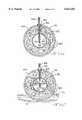
- FIG. 1is a view, partly elevational, partly cross-sectional, partly schematic and partly in block diagram of a Dewar container 10 including a liquid withdrawal conduit means 58 of the present invention associated with a pick-up head-means 60 floating on the surface of the cryogenic liquid 16.
- FIG. 2is an enlarged and broken away, partial elevational, partial cross-sectional view of one pair of capillary tubes 136 of the liquid withdrawal conduit means 58 passing through a septum 140.
- FIG. 3is a cross-sectional view of one embodiment of a float-type liquid pick-up head means of the present invention.
- FIG. 4is a partial elevational, partial cross-sectional view of the Dewar container 10 shown in FIG. 1 provided with a sinker-type liquid pick-up head means submerged in the cryogenic liquid 16.
- FIG. 5is a broken away, partial cross-sectional view of the Dewar container 10 shown in FIG. 4 rotated 90 degrees into a horizontal position.
- FIG. 6is a cross-sectional view of another embodiment of a sinker-type liquid pick-up head means according to the present invention.
- FIG. 7is a cross-sectional view of the sinker-type liquid pick-up head means shown in FIG. 6 partially immersed in the cryogenic liquid 16.
- FIG. 8is a bottom plan view of the sinker-type liquid pick-up head means shown in FIGS. 4 to 5.
- FIG. 9is a cross-sectional view along line 9--9 of FIG. 8.
- FIG. 10is an enlarged and broken away, partial elevational, partial cross-sectional view of the Dewar container 10 according to the present invention including a sinker-type pick-up head 116.
- FIGS. 1, 4 and 10show a cryogenic fluid Dewar container 10, partly in elevation, partly in schematic and partly in cross-section, which is suitable for use with the liquid withdrawal apparatus of the present invention.
- container 10is merely exemplary, and in that respect, container 10 represents one embodiment of a container that is useful with the liquid withdrawal apparatus of the present invention.
- the present liquid withdrawal apparatusis useful with many types of containers whose shape and construction are only limited by the imagination of those skilled in the art.
- container 10is shown having a generally cylindrical shape closed at both ends, the present liquid withdrawal apparatus can be adapted for use with containers having a myriad of shapes other than cylindrical. However, the container does need to be closed.
- the cryogenic liquid Dewar container 10comprises an outer container means or outer shell 12 mounted around and surrounding an inner container means or inner shell 14 containing a cryogenic liquid 16.
- the cryogenic liquid 16is a liquefied-gas mixture capable of supplying a breathable gas mixture to a breathing regulator 18 and an associated facepiece 20, as indicated in block diagram representation in FIG. 1.
- the outer shell 12has a generally cylindrical side wall extending along and around the longitudinal axis of the container 10 with first and second dome portions 12A and 12B closing the opposed ends thereof.
- the inner shell 14has a cylindrical side wall extending along and around the longitudinal axis with first and second dome portions 14A and 14B closing the opposed ends thereof.
- the space 22 formed between the coaxially aligned outer and inner shells 12 and 14is evacuated and provided with an insulation material (not shown) that helps to thermally insulate the cryogenic liquid 16 from the ambient environment.
- a getter material 24is mounted on the outside of the second dome 14B of the inner shell 14 to remove any residual gases in the evacuated space 22 between the shells 12 and 14 by a sorption process.
- This insulation structureis typically referred to as super insulation and is commonly used in the construction of liquefied gas containers.
- a liquid fill valve 26is mounted on the second dome 12B of the outer shell 12.
- Valve 26serves as a connection means for connecting the Dewar container 10 to a pressurized liquefied-gas supply (not shown) for filling the cryogenic liquid 16 into the inner shell 14.
- a tube 28supports a manifold block 30 positioned spaced above the first dome 14A of the inner shell 14, as oriented with respect to FIG. 1. Tube 28 depends into the interior of the inner shell 14, to provide a vent space where a gas pocket forms to prevent the inner shell from being overfilled, as is well known to those skilled in the art.
- the saturation vapor pressure of the cryogenic liquid 16 inside the inner shell 14is about 60 psig minimum, and more preferably at about 100 to 130 psig. The system will however operate at liquid saturation pressures well below 60 psig.
- a relief valve(not shown), compatible with cryogenic fluids, communicates with the interior of the inner shell 14. In case of over pressurization of the inner shell, the relief valve is set to actuate at about 140 psig.
- Valve 26leads to a gas trap 32 forming a 360 degree loop in the insulating space 22 between the shells 12 and 14.
- a gas trap 32forming a 360 degree loop in the insulating space 22 between the shells 12 and 14.
- valve 26When valve 26 is closed and with cryogenic liquid 16 provided in the inner shell 14, there will always be a high side of the trap 32 that is filled with gas.
- the difference in the coefficient of heat transfer of a gas compared to a liquidis on the order of magnitude of about ten to as much as a thousand for a boiling liquid. That way, trap 32 helps prevent ambient heat from conducting to the cryogenic liquid 16 in the inner shell 14.
- a first opening 34is provided in the upper dome 12A of the outer shell 12 and a second opening 36 is provided in the upper dome 14A of the inner shell 14.
- the perimeter of opening 34is spaced from a cylinder 38 having its lower end secured to the perimeter of the second opening 36 aligned along the longitudinal axis of the container 10.
- An annular flange 42has an enlarged base portion 44 secured to the perimeter of opening 34, spaced from the side wall of cylinder 38 with an inwardly extending upper annular rim 46 secured to the cylinder 38 adjacent to the annular connection.
- a cap 48is threaded on flange 42.
- Cap 48is provided with a central recess 50, a bottom wall 52 of which has an opening.
- Bottom wall 52supports a sleeve 54 fitted in a closely spaced relationship around a portion of the tube 28 communicating between the interior of the inner shell 14 and the exterior thereof.
- a compression nut 56is threaded on sleeve 54 to align the tube 28 and the manifold block 30.
- Tube 28partially sheaths a flexible liquid withdrawal conduit means 58 (shown partly in elevation and partly in dashed lines in FIGS. 1 and 4) having an end disposed inside of a pick-up head means 60 (FIGS. 1, 4 and 5) that ensures that the pick-up end of the conduit means 58 is always submerged below the surface of the cryogenic liquid 16, independent of the spatial orientation of the container 10.
- the pick-up means 60preferably has a spherical shape with a polished finish. This allows the pick-up head means 60 to translate on the inner surface of the inner shell 14 and decreases the coefficient of sliding friction between the pick-up head means 60 and the inner shell 14.
- the inner surface of the inner shellpreferably have a continuously curved configuration (not shown in FIGS. 1, 4, 5 and 10).
- the liquid withdrawal conduit means 58is of a polymeric material that is not adversely affected by contact with the cryogenic liquid 16.
- the tubescan be sheathed for additional mechanical strength.
- the first typeconsists of a float-type pick-up head (FIG. 1) which rests on the surface of the cryogenic liquid 16.
- Float 64is asymmetrically weighted to ensure that the pick-up end of the liquid withdrawal conduit means 58 is always in contact with the cryogenic liquid 16 as the liquid moves in the inner shell 14 in response to changing Dewar container 10 orientations.
- Another type of liquid pick-up head means 60comprises a weighted member, such as a sinker-type 66, as shown in FIGS. 4 and 5.
- the pick-up end of the liquid withdrawal conduit means 58is submerged in the cryogenic liquid 16 with the sinker 66 readily following the low side (FIG. 5) of the inner surface of the inner shell 14. That way, the sinker 66 ensures that the liquid withdrawal conduit means 58 is always in fluid flow communication with the liquid 16 until the liquid is essentially depleted from the inner shell 14, independent of the spatial orientation thereof.
- one embodiment of the float-type liquid pick-up headcomprises a spherically-shaped member 68 having a main opening 70 provided with a grommet 72.
- the liquid withdrawal conduit means 58pass through the grommet 72 and extend to a differential weight 74 disposed inside the sphere 68 opposite the main opening 70.
- the pick-up end of the four withdrawal conduits 58each terminate at respective openings 76 in the sphere 68. This structure maintains each of the withdrawal conduits 58 in fluid flow communication with the cryogenic liquid 16 in the inner shell 14 as the sphere 68 rests on the surface thereof.
- FIGS. 6 and 7show one embodiment of a sinker-type 66 liquid pick-up head comprising a spherically-shaped member 78.
- Sphere 78has a plurality of openings or perforations 80 therein for fluid flow communication of the cryogenic liquid 16 into the interior of the sphere 78.
- a wicking material 82such as a felt material and the like, is disposed inside the sphere 78 supporting a secondary sphere 84 at a central location therein.
- the secondary sphere 84is also hollow with a plurality of openings or perforations 86 that provide for fluid flow communication of the cryogenic fluid 16 therein.
- the sphere 78includes a main opening 88 provided with a grommet 90 having the withdrawal conduits 58 passing therethrough.
- the withdrawal conduits 58enter the secondary sphere 84 with their pick-up ends 92 positioned approximately at the center of the secondary sphere 84.
- the liquid 16enters the sphere 78 through the openings 80.
- the wicking material 82draws the cryogenic liquid 16 up into the sphere 78 to a level such that the cryogenic liquid 16 flows through the openings 92 and fills into the secondary sphere 84.
- the cryogenic liquid 16fills the secondary sphere 84 by capillary action to a level above the center point thereof and sufficient for fluid flow communication with the pick-up end of the withdrawal conduits 58.
- the pick-up end of conduits 58are fixed at the center point of secondary sphere 84 so that no matter the orientation of sphere 84, there is always fluid flow communication with the conduits 58.
- the openings 86 of the conduits 58can be disposed directly in the wicking material. In that case, the use of the secondary sphere 84 is not needed. Also, while not shown in the drawings, it will be readily apparent to those skilled in the art that the float-type pick-up head such as float 64 in FIG. 1 can also be provided with a wicking material inside the float to ensure contact of the liquid with the conduits 58, even when the liquid quantity is nearly depleted.
- FIGS. 8 and 9Another embodiment of the sinker-type 66 liquid pick-up head is shown in FIGS. 8 and 9, and it comprises a spherically-shaped weighted member 94.
- sphere 94is preferably made of a metal material having a sufficient mass to seek the low side of the inner surface of the inner shell 14, it can also be made of a plastic or other materials. In the latter case, the sphere 94 is weighted, for example by differential weight 74 shown in FIG. 3, to ensure that the withdrawal conduits 58 are always immersed in the cryogenic liquid 16 at the low side of the inner shell 14.
- Spherical member 94is provided with a sufficient number of through bores to receive the withdrawal conduits 58. There can be as few as one conduit 58, or as many as four or more of them.
- FIG. 9shows an exemplary conduit bore 96 comprising a first diameter passage 98 extending from an upper position on sphere 94 to an outwardly tapered frusto-conically shaped section 100. Passage 98 is sized to receive the withdrawal conduits 58 in a closely spaced relationship.
- Frusto-conical section 100leads to a threaded bore 102 having a diameter sized to receive a threaded insert 104.
- Insert 104has a first, large diameter opening 106 leading to a second inner fluid opening 108 having a lesser diameter extending to a central tap 110 provided with a frusto-conical shape.
- the spherical member 94is completed by a plurality of blind bores 114 drilled or otherwise formed extending therein.
- the blind bores 114are provided from both upper and lower positions on the sphere 94 and serve to remove weight from the sphere.
- FIG. 10shows still another embodiment of a sinker-type 66 liquid pick-up head comprising a generally hollow sphere 116 having the withdrawal conduits 58 associated therewith.
- Sphere 116has a plurality of openings or perforations 118 through its sidewall which provide for fluid flow of the cryogenic liquid 16 into and out of the interior thereof.
- a weighted block 120having a sufficient number of bores to receive the respective withdrawal conduits 58 is enclosed inside sphere 116.
- Bore 122is exemplary and it has a first portion 124 sized to receive one of the withdrawal conduits 58 in a closely spaced relationship therewith.
- the first portion 124 of bore 122leads to a second portion 126 having an outwardly extending frusto-conical taper that in turn forms into a cylindrically shaped portion.
- the cylindrical portionthreadingly receives an insert 128 that captures the pick-up end of the withdrawal conduit 58 there and in fluid flow communication with the cryogenic liquid 16 when the sphere 116 is immersed in the liquid.
- Sphere 116is not shown immersed in cryogenic liquid 16 in FIG. 10.
- Sphere 116is further provided with a number of tube openings 130 that receive the withdrawal conduits 58 for passage therein and eventually into the block 120.
- An elastomeric washer 132is fitted around each withdrawal conduit on the inside of sphere 116 while individual grommets 134 surround the tubes 62 proximate the outer surface of the sphere 116. The grommets 134 abut the outer surface of the sphere 116 and help prevent chaffing and wear of the withdrawal conduits 58 against the opening 130.
- the withdrawal conduits 58are in fluid flow communication between the pick-up head 60 through tube 28 to an upper end thereof where they separate into two pairs of conduits 136 and 138.
- Each conduit pair 136 and 138passes through a corresponding pressure barrier, such as septums 140 and 142 disposed inside passages in the manifold block 30 and lead into respective heat exchangers 144 and 146 (shown in dashed lines in FIG. 1).
- the bifurcation of the withdrawn liquid into two heat exchangers 144 and 146benefits the dynamics of vaporization of the liquid to a gaseous phase and helps maintain a uniform pressure profile through the entire length of the system.
- the use of two heat exchangersis not necessary for proper functioning of the present invention.
- Septum 140is exemplary. As particularly shown in FIG. 2, the pair of conduits 136 communicate through the septum 140 received in a passage 148 in the manifold block 30.
- the septum 140is secured in passage 148 with a nut 150 threaded therein.
- a washer 152abuts the nut 150 and is locked in place with a fitting 154 threaded into the passage 148.
- the downstream end of fitting 154is provided with an inner frusto-conically shaped taper 156 that receives an annular elastomeric wedge 158 sealed around an intermediate conduit 160 leading to a heat exchanger conduit 162 connected to heat exchanger 144.
- a union nut 164is threaded onto the downstream end of the fitting 154 to secure the seal 158 around the intermediate conduit 160.
- This constructionensures that the septum 140 captures the pair of conduits 136 sealed in respective openings therethrough so that there is little or no communication of pressure (or mass) between the inside of the inner shell 14 and the endothermic heat exchanger 144, other than the communication path afforded by the inside of the pair of conduits 136 themselves.
- the other pair of conduits 138 and its septum 142is similar in construction and, as shown in FIGS.
- the heat exchangers 144 and 146which serve as a removal means, each receive about one half of the liquid removed from the container and they serve to transfer heat from the ambient atmosphere to the cryogenic liquid 16, which preferably is a liquefied breathable gas mixture, to vaporize the liquid to a gas and then to warm the gas to a breathable temperature.
- An outboard end of the endothermic heat exchangers 144, 146merges at a manifold (not shown) that connects to a flexible breathing hose 176 that supplies the warmed gas to the breathing pressure regulator 18 and an associated facepiece 20 worn by the user breathing or otherwise consuming the gas mixture, as shown schematically in FIG. 1.
- the septa 140, 142ensure that the sole path of pressure and mass communication between the inside of the inner shell 14 and the heat exchangers 144, 146 is through the withdrawal conduit 58 to maintain the uniform system pressure up to the regulator.
- the cryogenic liquid 16is preferably at a saturated liquid pressure of between about 100 to 130 psig, and this operating pressure is transmitted through the entire length of the withdrawal system.
- Dewar container 10is intended for use by people needing to breath in a hostile environment where the atmosphere may not be conducive to supporting life. In that respect and initially referring to FIG. 1, a user will first don the facepiece 20 and associated breathing gas regulator 18 while the container 10 is carried on the back by a harness, as is well known to those of ordinary skill in the art.
- Inner shell 14has previously been filled with cryogenic liquid 16 at a liquid saturation pressure of about 100 to 130 psig.
- the cryogenic liquid 16is preferably a breathable gas mixture.
- the regulator 18 associated with the facepiece 20is then actuated and breathing begins.
- the various pick-up heads means 60i.e. the float-type members shown in FIGS. 1 and 3 and the sinker-type members shown in FIGS. 4 to 10 ensure that the inlet to the withdrawal conduits 58 are in fluid flow communication with the liquid 16, independent of the spatial orientation of the Dewar 10.
- the withdrawal conduitssplit into the conduit pairs 136 and 138 which transmit through the septa 140, 142 and deliver the liquid 16 to the respective heat exchangers 144 and 146.
- the septa 140, 142ensure that the only communication path between the inside of the inner shell 14 and the endothermic heat exchangers 144, 146 is afforded by the withdrawal conduit 58 themselves.
- the outlet of the withdrawal conduit 58empties into the heat exchangers 144, 146 which transfer heat from the ambient atmosphere to the cryogenic liquid, thereby vaporizing the liquid to a gas and then warm the gas to about ambient temperature. Alternatively, the gas can be warmed to a cooler temperature than ambient if so desired.
- the heat exchangers 144 and 146maintain the concentration of the various constituents consisting of the liquified gas mixture at a similar concentration as they are in the liquid phase.
- the breathable gas mixtureflows from the heat exchangers to a manifold (not shown) that connects to the flexible breathing hose 176 (FIG. 1) leading to the regulator 18 which is attached to the facepiece 20.
- cryogenic liquid 16 at about 100 to 130 psigis transmitted through the conduit pairs 136 and 138 and the heat exchangers 144 and 146 where heat is transferred to the liquid to first provide a raised fluid and as further heat is transferred, the gas is warmed to about ambient temperature and made suitable for breathing.
- this breathable gascommunicates to the regulator 18 attached to the facepiece 20 such that the entire system including the liquid withdrawal conduit means 58, the heat exchangers 144 and 146 and the breathing hose 176 leading to the facepiece regulator 18 are approximately at the pressure of the saturated liquid, i.e.
- the regulatorprovides the breathing gas to the facepiece 20 on demand while maintaining a positive pressure inside the facepiece of about 0 to 2 inches water column above the pressure outside the facepiece.
- the regulator 18, which serves as a consumption means for the breathable gasalso can be used in a constant flow mode or any other mode of operation, as is well known to those skilled in the art.
- the pressure of the resulting gas phaseincreases.
- the pressure in the heat exchangers 144 and 146essentially equals the pressure inside the inner shell 14, i.e. about 100 to 130 psig, (neglecting hardware pressure drop considerations) liquid 16 removal through the conduits 58 ceases.
- any withdrawal of warmed gas from the downstream end of the heat exchangersfor instance as the user inhales during a normal respiratory demand requirement, causes the pressure in the heat exchangers 144 and 146 to decrease.
- the inner shell 14is charged with a liquid mixture saturated at a pressure within this range.
- the head gases inside the inner shell 14do not get consumed during the respiratory demand cycles because of the septa 140, 142, and the liquid removal or withdrawal system operates at 100 to 130 psig until the liquid contents are depleted.
Landscapes
- Health & Medical Sciences (AREA)
- Engineering & Computer Science (AREA)
- Mechanical Engineering (AREA)
- General Engineering & Computer Science (AREA)
- Emergency Medicine (AREA)
- Pulmonology (AREA)
- General Health & Medical Sciences (AREA)
- Business, Economics & Management (AREA)
- Emergency Management (AREA)
- Filling Or Discharging Of Gas Storage Vessels (AREA)
Abstract
Description
Claims (29)
Priority Applications (3)
| Application Number | Priority Date | Filing Date | Title |
|---|---|---|---|
| US08/951,138US6012453A (en) | 1995-04-20 | 1997-10-15 | Apparatus for withdrawal of liquid from a container and method |
| AU98039/98AAU9803998A (en) | 1997-10-15 | 1998-10-14 | Apparatus for withdrawal of liquid from a container and method |
| PCT/US1998/021722WO1999019663A1 (en) | 1997-10-15 | 1998-10-14 | Apparatus for withdrawal of liquid from a container and method |
Applications Claiming Priority (2)
| Application Number | Priority Date | Filing Date | Title |
|---|---|---|---|
| US42591695A | 1995-04-20 | 1995-04-20 | |
| US08/951,138US6012453A (en) | 1995-04-20 | 1997-10-15 | Apparatus for withdrawal of liquid from a container and method |
Related Parent Applications (1)
| Application Number | Title | Priority Date | Filing Date |
|---|---|---|---|
| US42591695AContinuation-In-Part | 1995-04-20 | 1995-04-20 |
Publications (1)
| Publication Number | Publication Date |
|---|---|
| US6012453Atrue US6012453A (en) | 2000-01-11 |
Family
ID=25491316
Family Applications (1)
| Application Number | Title | Priority Date | Filing Date |
|---|---|---|---|
| US08/951,138Expired - LifetimeUS6012453A (en) | 1995-04-20 | 1997-10-15 | Apparatus for withdrawal of liquid from a container and method |
Country Status (3)
| Country | Link |
|---|---|
| US (1) | US6012453A (en) |
| AU (1) | AU9803998A (en) |
| WO (1) | WO1999019663A1 (en) |
Cited By (38)
| Publication number | Priority date | Publication date | Assignee | Title |
|---|---|---|---|---|
| US6254148B1 (en)* | 1997-02-04 | 2001-07-03 | Atoma International Corp. | Vehicle door locking system with separate power operated inner door and outer door locking mechanisms |
| US6289892B1 (en)* | 1991-05-03 | 2001-09-18 | Alliance Pharmaceutical Corp. | Partial liquid breathing of fluorocarbons |
| WO2002055924A1 (en)* | 2001-01-13 | 2002-07-18 | W L Gore & Associates (Uk) Ltd. | Cryogenic liquid delivery system with microporous phase separator |
| US6575159B1 (en)* | 1999-10-29 | 2003-06-10 | Mallinckrodt Inc. | Portable liquid oxygen unit with multiple operational orientations |
| US6651653B1 (en)* | 1997-06-16 | 2003-11-25 | Sequal Technologies, Inc. | Methods and apparatus to generate liquid ambulatory oxygen from an oxygen concentrator |
| US20040040941A1 (en)* | 2002-09-03 | 2004-03-04 | Ecklund Steven P. | Methods and apparatus for removing gases from enclosures |
| US20050066666A1 (en)* | 2003-09-26 | 2005-03-31 | Hall Ivan Keith | Cryogenic vessel with an ullage space venturi assembly |
| US20060008392A1 (en)* | 2004-07-08 | 2006-01-12 | Graham David R | Storage and delivery systems for gases held in liquid medium |
| US20060278224A1 (en)* | 2005-06-09 | 2006-12-14 | Temple University-Of The Commonwealth System Of Higher Education | Process for transient and steady state delivery of biological agents to the lung via breathable liquids |
| US20070217967A1 (en)* | 2004-07-08 | 2007-09-20 | Mcdermott Wayne T | Wick systems for complexed gas technology |
| US20080140061A1 (en)* | 2006-09-08 | 2008-06-12 | Arbel Medical Ltd. | Method And Device For Combined Treatment |
| US20080208181A1 (en)* | 2007-01-19 | 2008-08-28 | Arbel Medical Ltd. | Thermally Insulated Needles For Dermatological Applications |
| US20080307800A1 (en)* | 2007-06-14 | 2008-12-18 | Arbel Medical Ltd. | Siphon for Delivery of Liquid Cryogen from Dewar Flask |
| US20090129946A1 (en)* | 2007-11-21 | 2009-05-21 | Arbel Medical, Ltd. | Pumping unit for delivery of liquid medium from a vessel |
| US20100162730A1 (en)* | 2007-06-14 | 2010-07-01 | Arbel Medical Ltd. | Siphon for delivery of liquid cryogen from dewar flask |
| US20100234670A1 (en)* | 2009-03-12 | 2010-09-16 | Eyal Shai | Combined cryotherapy and brachytherapy device and method |
| US20100281917A1 (en)* | 2008-11-05 | 2010-11-11 | Alexander Levin | Apparatus and Method for Condensing Contaminants for a Cryogenic System |
| US20100305439A1 (en)* | 2009-05-27 | 2010-12-02 | Eyal Shai | Device and Method for Three-Dimensional Guidance and Three-Dimensional Monitoring of Cryoablation |
| US20100324546A1 (en)* | 2007-07-09 | 2010-12-23 | Alexander Levin | Cryosheath |
| US20110015624A1 (en)* | 2008-01-15 | 2011-01-20 | Icecure Medical Ltd. | Cryosurgical instrument insulating system |
| US7938822B1 (en) | 2010-05-12 | 2011-05-10 | Icecure Medical Ltd. | Heating and cooling of cryosurgical instrument using a single cryogen |
| US7967815B1 (en) | 2010-03-25 | 2011-06-28 | Icecure Medical Ltd. | Cryosurgical instrument with enhanced heat transfer |
| US7967814B2 (en) | 2009-02-05 | 2011-06-28 | Icecure Medical Ltd. | Cryoprobe with vibrating mechanism |
| US8080005B1 (en) | 2010-06-10 | 2011-12-20 | Icecure Medical Ltd. | Closed loop cryosurgical pressure and flow regulated system |
| US8083733B2 (en) | 2008-04-16 | 2011-12-27 | Icecure Medical Ltd. | Cryosurgical instrument with enhanced heat exchange |
| US8899226B2 (en) | 2006-02-14 | 2014-12-02 | Bcs Life Support, Llc | Apparatus for drawing a cryogenic liquid from a container |
| WO2015066448A1 (en)* | 2013-11-01 | 2015-05-07 | Advanced Technology Materials, Inc. | Apparatus and method for direct contact pressure dispensing using floating liquid extraction element |
| US9353618B2 (en) | 2012-10-31 | 2016-05-31 | Baker Hughes Incorporated | Apparatus and methods for cooling downhole devices |
| US20160158927A1 (en)* | 2011-10-03 | 2016-06-09 | Illinois Tool Works Inc. | Portable pressurized power source for fastener driving tool |
| US20180245740A1 (en)* | 2017-02-24 | 2018-08-30 | Robert D. Kaminsky | Method of Purging a Dual Purpose LNG/LIN Storage Tank |
| US20180252366A1 (en)* | 2015-08-20 | 2018-09-06 | Linde Aktiengesellschaft | Foot-in-foot mounting of cryogenic storage containers |
| US20180259128A1 (en)* | 2015-09-15 | 2018-09-13 | L'air Liquide, Societe Anonyme Pour I'etude Et I'exploitation Des Procedes Georges Claude | Liquefied-fluid storage tank |
| CN114307019A (en)* | 2021-12-24 | 2022-04-12 | 哲弗智能系统(上海)有限公司 | Fire extinguishing device |
| US11633224B2 (en) | 2020-02-10 | 2023-04-25 | Icecure Medical Ltd. | Cryogen pump |
| US20240142061A1 (en)* | 2022-10-31 | 2024-05-02 | China Special Equipment Inspection & Research Institute | Anti-leakage device for hydrogen storage container |
| US12215811B2 (en) | 2022-07-18 | 2025-02-04 | Icecure Medical Ltd. | Cryogenic system connector |
| US20250060072A1 (en)* | 2021-12-22 | 2025-02-20 | Faurecia Hydrogen Solutions France | Cryogenic fluid storage unit |
| US12426934B2 (en) | 2022-02-28 | 2025-09-30 | Icecure Medical Ltd. | Cryogen flow control |
Families Citing this family (1)
| Publication number | Priority date | Publication date | Assignee | Title |
|---|---|---|---|---|
| CN103383063A (en)* | 2013-06-09 | 2013-11-06 | 苏州华福低温容器有限公司 | Gas-seal structure of pressure input pipe of movable type low-temperature pressure vessel |
Citations (34)
| Publication number | Priority date | Publication date | Assignee | Title |
|---|---|---|---|---|
| US33567A (en)* | 1861-10-29 | Improvement in washing-machines | ||
| US1395753A (en)* | 1920-10-30 | 1921-11-01 | Louis A Wehle | Apparatus for use in preparing liquid or semiliquid materials |
| DE414107C (en)* | 1919-06-03 | 1925-05-25 | Fluessige Gase G M B H Fa | Breathing apparatus for liquid gases |
| US1845136A (en)* | 1930-10-08 | 1932-02-16 | Dieter William | Airplane engine |
| US1955308A (en)* | 1932-06-25 | 1934-04-17 | George W Naftel | Siphonic fertilizer applicator |
| CA467014A (en)* | 1950-08-01 | Grayson-Smith Hugh | Liquid oxygen evaporators | |
| US2583932A (en)* | 1950-04-22 | 1952-01-29 | Harold E Daebelliehn | Fuel tank for captive model airplanes |
| US2970452A (en)* | 1959-04-01 | 1961-02-07 | Union Carbide Corp | Method and apparatus for supplying liquefied gas |
| US2990695A (en)* | 1958-10-06 | 1961-07-04 | Bendix Corp | Thermodynamic transfer systems |
| US3046751A (en)* | 1960-03-09 | 1962-07-31 | Bendix Corp | Conversion apparatus and systems |
| US3097497A (en)* | 1959-08-14 | 1963-07-16 | Normalair Ltd | Oxygen supply systems |
| US3318307A (en)* | 1964-08-03 | 1967-05-09 | Firewel Company Inc | Breathing pack for converting liquid air or oxygen into breathable gas |
| US3332411A (en)* | 1965-09-07 | 1967-07-25 | Roper Corp Geo D | Lubrication system for chain saws |
| US3570481A (en)* | 1968-10-23 | 1971-03-16 | Cryogenic Systems Inc | Cryogenic underwater breathing apparatus |
| US3572048A (en)* | 1968-10-14 | 1971-03-23 | Wiremold Co | Ominpositional cryogenic underwater breathind apparatus |
| US3679092A (en)* | 1969-09-15 | 1972-07-25 | Sullivan Products Inc | Fuel tank for use in model airplanes |
| US3699775A (en)* | 1969-12-11 | 1972-10-24 | Sub Marine Systems Inc | Gas and liquid processing system |
| US3706208A (en)* | 1971-01-13 | 1972-12-19 | Air Prod & Chem | Flexible cryogenic liquid transfer system and improved support means therefor |
| US3707078A (en)* | 1971-02-10 | 1972-12-26 | Bendix Corp | Fail-safe liquid oxygen to gaseous oxygen conversion system |
| US3869871A (en)* | 1973-05-03 | 1975-03-11 | Alexei Petrovich Rybalko | Gas and heat protective garment |
| US3892273A (en)* | 1973-07-09 | 1975-07-01 | Perkin Elmer Corp | Heat pipe lobar wicking arrangement |
| US4211086A (en)* | 1977-10-11 | 1980-07-08 | Beatrice Foods Company | Cryogenic breathing system |
| US4218892A (en)* | 1979-03-29 | 1980-08-26 | Nasa | Low cost cryostat |
| US4370809A (en)* | 1980-03-26 | 1983-02-01 | Kioritz Corporation | Power chain saw |
| US4602656A (en)* | 1983-09-07 | 1986-07-29 | Kioritz Corporation | Receptacle for use in a portable power driven machine |
| US4750551A (en)* | 1980-09-16 | 1988-06-14 | Casey Charles B | Apparatus for and method of heat transfer |
| US4756310A (en)* | 1982-05-28 | 1988-07-12 | Hemodynamics Technology, Inc. | System for cooling an area of the surface of an object |
| US4835866A (en)* | 1986-12-17 | 1989-06-06 | Kioritz Corporation | Device for mounting carburetor on internal combustion engine |
| USRE33567E (en) | 1986-02-25 | 1991-04-09 | Micromeritics Instrument Corporation | Temperature controlling apparatus for use with pore volume and surface area analyzers |
| US5086619A (en)* | 1990-06-15 | 1992-02-11 | Nicolet Instrument Corporation | Filler apparatus for providing cryogenic liquid coolant to dewars such as those used in radiation detectors |
| US5243826A (en)* | 1992-07-01 | 1993-09-14 | Apd Cryogenics Inc. | Method and apparatus for collecting liquid cryogen |
| WO1994008177A2 (en)* | 1992-10-06 | 1994-04-14 | Oceaneering International, Inc. | Apparatus for storing and delivering liquid cryogen and apparatus and process for filling same |
| US5353835A (en)* | 1993-09-23 | 1994-10-11 | Ingersoll-Rand Company | Air tank drain |
| US5417073A (en)* | 1993-07-16 | 1995-05-23 | Superconductor Technologies Inc. | Cryogenic cooling system |
Family Cites Families (4)
| Publication number | Priority date | Publication date | Assignee | Title |
|---|---|---|---|---|
| US2580710A (en)* | 1946-02-13 | 1952-01-01 | William A Wildhack | Liquid oxygen converter |
| US3202160A (en)* | 1961-05-24 | 1965-08-24 | Dynatech Corp | Method and apparatus for orienting fluids in zero gravity fields |
| DE4411338A1 (en)* | 1994-03-31 | 1995-10-05 | Air Liquide Gmbh | Suppressing the vapour pressure above liquefied gas in cryogenic vessel |
| EP0824647B1 (en)* | 1995-04-20 | 1999-01-07 | Scott Technologies, Inc. | Apparatus for withdrawal of liquid from a container and method |
- 1997
- 1997-10-15USUS08/951,138patent/US6012453A/ennot_activeExpired - Lifetime
- 1998
- 1998-10-14AUAU98039/98Apatent/AU9803998A/ennot_activeAbandoned
- 1998-10-14WOPCT/US1998/021722patent/WO1999019663A1/enactiveApplication Filing
Patent Citations (36)
| Publication number | Priority date | Publication date | Assignee | Title |
|---|---|---|---|---|
| US33567A (en)* | 1861-10-29 | Improvement in washing-machines | ||
| CA467014A (en)* | 1950-08-01 | Grayson-Smith Hugh | Liquid oxygen evaporators | |
| DE414107C (en)* | 1919-06-03 | 1925-05-25 | Fluessige Gase G M B H Fa | Breathing apparatus for liquid gases |
| US1395753A (en)* | 1920-10-30 | 1921-11-01 | Louis A Wehle | Apparatus for use in preparing liquid or semiliquid materials |
| US1845136A (en)* | 1930-10-08 | 1932-02-16 | Dieter William | Airplane engine |
| US1955308A (en)* | 1932-06-25 | 1934-04-17 | George W Naftel | Siphonic fertilizer applicator |
| US2583932A (en)* | 1950-04-22 | 1952-01-29 | Harold E Daebelliehn | Fuel tank for captive model airplanes |
| US2990695A (en)* | 1958-10-06 | 1961-07-04 | Bendix Corp | Thermodynamic transfer systems |
| US2970452A (en)* | 1959-04-01 | 1961-02-07 | Union Carbide Corp | Method and apparatus for supplying liquefied gas |
| US3097497A (en)* | 1959-08-14 | 1963-07-16 | Normalair Ltd | Oxygen supply systems |
| US3046751A (en)* | 1960-03-09 | 1962-07-31 | Bendix Corp | Conversion apparatus and systems |
| US3318307A (en)* | 1964-08-03 | 1967-05-09 | Firewel Company Inc | Breathing pack for converting liquid air or oxygen into breathable gas |
| US3332411A (en)* | 1965-09-07 | 1967-07-25 | Roper Corp Geo D | Lubrication system for chain saws |
| US3572048A (en)* | 1968-10-14 | 1971-03-23 | Wiremold Co | Ominpositional cryogenic underwater breathind apparatus |
| US3570481A (en)* | 1968-10-23 | 1971-03-16 | Cryogenic Systems Inc | Cryogenic underwater breathing apparatus |
| US3679092A (en)* | 1969-09-15 | 1972-07-25 | Sullivan Products Inc | Fuel tank for use in model airplanes |
| US3699775A (en)* | 1969-12-11 | 1972-10-24 | Sub Marine Systems Inc | Gas and liquid processing system |
| US3706208A (en)* | 1971-01-13 | 1972-12-19 | Air Prod & Chem | Flexible cryogenic liquid transfer system and improved support means therefor |
| US3707078A (en)* | 1971-02-10 | 1972-12-26 | Bendix Corp | Fail-safe liquid oxygen to gaseous oxygen conversion system |
| US3869871A (en)* | 1973-05-03 | 1975-03-11 | Alexei Petrovich Rybalko | Gas and heat protective garment |
| US3892273A (en)* | 1973-07-09 | 1975-07-01 | Perkin Elmer Corp | Heat pipe lobar wicking arrangement |
| US4211086A (en)* | 1977-10-11 | 1980-07-08 | Beatrice Foods Company | Cryogenic breathing system |
| US4218892A (en)* | 1979-03-29 | 1980-08-26 | Nasa | Low cost cryostat |
| US4370809A (en)* | 1980-03-26 | 1983-02-01 | Kioritz Corporation | Power chain saw |
| US4750551A (en)* | 1980-09-16 | 1988-06-14 | Casey Charles B | Apparatus for and method of heat transfer |
| US4756310A (en)* | 1982-05-28 | 1988-07-12 | Hemodynamics Technology, Inc. | System for cooling an area of the surface of an object |
| US4602656A (en)* | 1983-09-07 | 1986-07-29 | Kioritz Corporation | Receptacle for use in a portable power driven machine |
| USRE33567E (en) | 1986-02-25 | 1991-04-09 | Micromeritics Instrument Corporation | Temperature controlling apparatus for use with pore volume and surface area analyzers |
| US4835866A (en)* | 1986-12-17 | 1989-06-06 | Kioritz Corporation | Device for mounting carburetor on internal combustion engine |
| US5086619A (en)* | 1990-06-15 | 1992-02-11 | Nicolet Instrument Corporation | Filler apparatus for providing cryogenic liquid coolant to dewars such as those used in radiation detectors |
| US5243826A (en)* | 1992-07-01 | 1993-09-14 | Apd Cryogenics Inc. | Method and apparatus for collecting liquid cryogen |
| WO1994008177A2 (en)* | 1992-10-06 | 1994-04-14 | Oceaneering International, Inc. | Apparatus for storing and delivering liquid cryogen and apparatus and process for filling same |
| US5438837A (en)* | 1992-10-06 | 1995-08-08 | Oceaneering International, Inc. | Apparatus for storing and delivering liquid cryogen and apparatus and process for filling same |
| US5438837B1 (en)* | 1992-10-06 | 1999-07-27 | Oceaneering Int Inc | Apparatus for storing and delivering liquid cryogen and apparatus and process for filling same |
| US5417073A (en)* | 1993-07-16 | 1995-05-23 | Superconductor Technologies Inc. | Cryogenic cooling system |
| US5353835A (en)* | 1993-09-23 | 1994-10-11 | Ingersoll-Rand Company | Air tank drain |
Cited By (59)
| Publication number | Priority date | Publication date | Assignee | Title |
|---|---|---|---|---|
| US6289892B1 (en)* | 1991-05-03 | 2001-09-18 | Alliance Pharmaceutical Corp. | Partial liquid breathing of fluorocarbons |
| US6341807B2 (en) | 1997-02-04 | 2002-01-29 | Atoma International Corp. | Vehicle door locking system with separate power operated inner door and outer door locking mechanisms |
| US6554328B2 (en) | 1997-02-04 | 2003-04-29 | Atoma International Corporation | Vehicle door locking system with separate power operated inner door and outer door locking mechanisms |
| US6254148B1 (en)* | 1997-02-04 | 2001-07-03 | Atoma International Corp. | Vehicle door locking system with separate power operated inner door and outer door locking mechanisms |
| US6651653B1 (en)* | 1997-06-16 | 2003-11-25 | Sequal Technologies, Inc. | Methods and apparatus to generate liquid ambulatory oxygen from an oxygen concentrator |
| USRE43398E1 (en) | 1997-06-16 | 2012-05-22 | Respironics, Inc. | Methods and apparatus to generate liquid ambulatory oxygen from an oxygen concentrator |
| US7296569B2 (en)* | 1999-10-29 | 2007-11-20 | Mallinckrodt, Inc. | Portable liquid oxygen unit with multiple operational orientations |
| US7766009B2 (en) | 1999-10-29 | 2010-08-03 | Caire Inc. | Portable liquid oxygen unit with multiple operational orientations |
| US20050098174A1 (en)* | 1999-10-29 | 2005-05-12 | Mallinckrodt Inc. | Portable liquid oxygen unit with multiple operational orientations |
| US6575159B1 (en)* | 1999-10-29 | 2003-06-10 | Mallinckrodt Inc. | Portable liquid oxygen unit with multiple operational orientations |
| US20040074240A1 (en)* | 2001-01-13 | 2004-04-22 | Mark Robbie | Cryogenic Liquid delivery system with micropopous phase separator |
| WO2002055924A1 (en)* | 2001-01-13 | 2002-07-18 | W L Gore & Associates (Uk) Ltd. | Cryogenic liquid delivery system with microporous phase separator |
| US20040040941A1 (en)* | 2002-09-03 | 2004-03-04 | Ecklund Steven P. | Methods and apparatus for removing gases from enclosures |
| US6931711B2 (en) | 2002-09-03 | 2005-08-23 | Honeywell International Inc. | Methods and apparatus for removing gases from enclosures |
| US6904758B2 (en)* | 2003-09-26 | 2005-06-14 | Harsco Technologies Corporation | Cryogenic vessel with an ullage space venturi assembly |
| US7131277B2 (en) | 2003-09-26 | 2006-11-07 | Harsco Technologies Corporation | Cryogenic vessel with an ullage space venturi assembly |
| US20060037328A1 (en)* | 2003-09-26 | 2006-02-23 | Harsco Technologies Corporation | Cryogenic vessel with an ullage space venturi assembly |
| US20050066666A1 (en)* | 2003-09-26 | 2005-03-31 | Hall Ivan Keith | Cryogenic vessel with an ullage space venturi assembly |
| US20070217967A1 (en)* | 2004-07-08 | 2007-09-20 | Mcdermott Wayne T | Wick systems for complexed gas technology |
| US20060008392A1 (en)* | 2004-07-08 | 2006-01-12 | Graham David R | Storage and delivery systems for gases held in liquid medium |
| US7396381B2 (en) | 2004-07-08 | 2008-07-08 | Air Products And Chemicals, Inc. | Storage and delivery systems for gases held in liquid medium |
| US7648682B2 (en)* | 2004-07-08 | 2010-01-19 | Air Products And Chemicals, Inc. | Wick systems for complexed gas technology |
| US20060278224A1 (en)* | 2005-06-09 | 2006-12-14 | Temple University-Of The Commonwealth System Of Higher Education | Process for transient and steady state delivery of biological agents to the lung via breathable liquids |
| US8375943B2 (en) | 2005-06-09 | 2013-02-19 | Temple University—Of the Commonwealth System of Higher Education | Process for transient and steady state delivery of biological agents to the lung via breathable liquids |
| US20110162646A1 (en)* | 2005-06-09 | 2011-07-07 | Temple University - Of The Commonwealth System Of Higher Education | Process for transient and steady state delivery of biological agents to the lung via breathable liquids |
| US7909031B2 (en) | 2005-06-09 | 2011-03-22 | Temple Univesity - Of The Commonwealth System of Higher Education | Process for transient and steady state delivery of biological agents to the lung via breathable liquids |
| US8899226B2 (en) | 2006-02-14 | 2014-12-02 | Bcs Life Support, Llc | Apparatus for drawing a cryogenic liquid from a container |
| US20080140061A1 (en)* | 2006-09-08 | 2008-06-12 | Arbel Medical Ltd. | Method And Device For Combined Treatment |
| US20080208181A1 (en)* | 2007-01-19 | 2008-08-28 | Arbel Medical Ltd. | Thermally Insulated Needles For Dermatological Applications |
| US20100162730A1 (en)* | 2007-06-14 | 2010-07-01 | Arbel Medical Ltd. | Siphon for delivery of liquid cryogen from dewar flask |
| US20080307800A1 (en)* | 2007-06-14 | 2008-12-18 | Arbel Medical Ltd. | Siphon for Delivery of Liquid Cryogen from Dewar Flask |
| US20100324546A1 (en)* | 2007-07-09 | 2010-12-23 | Alexander Levin | Cryosheath |
| US20090129946A1 (en)* | 2007-11-21 | 2009-05-21 | Arbel Medical, Ltd. | Pumping unit for delivery of liquid medium from a vessel |
| US20110015624A1 (en)* | 2008-01-15 | 2011-01-20 | Icecure Medical Ltd. | Cryosurgical instrument insulating system |
| US8083733B2 (en) | 2008-04-16 | 2011-12-27 | Icecure Medical Ltd. | Cryosurgical instrument with enhanced heat exchange |
| US20100281917A1 (en)* | 2008-11-05 | 2010-11-11 | Alexander Levin | Apparatus and Method for Condensing Contaminants for a Cryogenic System |
| US7967814B2 (en) | 2009-02-05 | 2011-06-28 | Icecure Medical Ltd. | Cryoprobe with vibrating mechanism |
| US8162812B2 (en) | 2009-03-12 | 2012-04-24 | Icecure Medical Ltd. | Combined cryotherapy and brachytherapy device and method |
| US20100234670A1 (en)* | 2009-03-12 | 2010-09-16 | Eyal Shai | Combined cryotherapy and brachytherapy device and method |
| US20100305439A1 (en)* | 2009-05-27 | 2010-12-02 | Eyal Shai | Device and Method for Three-Dimensional Guidance and Three-Dimensional Monitoring of Cryoablation |
| US7967815B1 (en) | 2010-03-25 | 2011-06-28 | Icecure Medical Ltd. | Cryosurgical instrument with enhanced heat transfer |
| US7938822B1 (en) | 2010-05-12 | 2011-05-10 | Icecure Medical Ltd. | Heating and cooling of cryosurgical instrument using a single cryogen |
| US8080005B1 (en) | 2010-06-10 | 2011-12-20 | Icecure Medical Ltd. | Closed loop cryosurgical pressure and flow regulated system |
| US10293470B2 (en)* | 2011-10-03 | 2019-05-21 | Illinois Tool Works Inc. | Portable pressurized power source for fastener driving tool |
| US20160158927A1 (en)* | 2011-10-03 | 2016-06-09 | Illinois Tool Works Inc. | Portable pressurized power source for fastener driving tool |
| US9353618B2 (en) | 2012-10-31 | 2016-05-31 | Baker Hughes Incorporated | Apparatus and methods for cooling downhole devices |
| EP3617443A1 (en)* | 2012-10-31 | 2020-03-04 | Baker Hughes, A Ge Company, Llc | Apparatus and methods for cooling downhole devices |
| WO2015066448A1 (en)* | 2013-11-01 | 2015-05-07 | Advanced Technology Materials, Inc. | Apparatus and method for direct contact pressure dispensing using floating liquid extraction element |
| US20180252366A1 (en)* | 2015-08-20 | 2018-09-06 | Linde Aktiengesellschaft | Foot-in-foot mounting of cryogenic storage containers |
| US20180259128A1 (en)* | 2015-09-15 | 2018-09-13 | L'air Liquide, Societe Anonyme Pour I'etude Et I'exploitation Des Procedes Georges Claude | Liquefied-fluid storage tank |
| US10781975B2 (en)* | 2015-09-15 | 2020-09-22 | L'air Liquide Societe Anonyme Pour L'etude Et L'exploitation Des Procedes Georges Claude | Liquefied-fluid storage tank |
| US20180245740A1 (en)* | 2017-02-24 | 2018-08-30 | Robert D. Kaminsky | Method of Purging a Dual Purpose LNG/LIN Storage Tank |
| US10663115B2 (en)* | 2017-02-24 | 2020-05-26 | Exxonmobil Upstream Research Company | Method of purging a dual purpose LNG/LIN storage tank |
| US11633224B2 (en) | 2020-02-10 | 2023-04-25 | Icecure Medical Ltd. | Cryogen pump |
| US20250060072A1 (en)* | 2021-12-22 | 2025-02-20 | Faurecia Hydrogen Solutions France | Cryogenic fluid storage unit |
| CN114307019A (en)* | 2021-12-24 | 2022-04-12 | 哲弗智能系统(上海)有限公司 | Fire extinguishing device |
| US12426934B2 (en) | 2022-02-28 | 2025-09-30 | Icecure Medical Ltd. | Cryogen flow control |
| US12215811B2 (en) | 2022-07-18 | 2025-02-04 | Icecure Medical Ltd. | Cryogenic system connector |
| US20240142061A1 (en)* | 2022-10-31 | 2024-05-02 | China Special Equipment Inspection & Research Institute | Anti-leakage device for hydrogen storage container |
Also Published As
| Publication number | Publication date |
|---|---|
| WO1999019663A1 (en) | 1999-04-22 |
| AU9803998A (en) | 1999-05-03 |
Similar Documents
| Publication | Publication Date | Title |
|---|---|---|
| US6012453A (en) | Apparatus for withdrawal of liquid from a container and method | |
| US2970452A (en) | Method and apparatus for supplying liquefied gas | |
| JP5161083B2 (en) | Portable liquid oxygen supply device | |
| US3376588A (en) | Buoy with buoyancy produced by liquefied gas vaporization | |
| US5438837A (en) | Apparatus for storing and delivering liquid cryogen and apparatus and process for filling same | |
| ES2335592T3 (en) | FLUID STORAGE AND DISPENSATION SYSTEM. | |
| US6513521B1 (en) | Cryogenic mixed gas single phase storage and delivery | |
| US2576985A (en) | Liquid oxygen converter | |
| US4586500A (en) | Breathing apparatus | |
| US3190081A (en) | Cryogenic applicator with probe means | |
| US5561983A (en) | Cryogenic liquid delivery system | |
| US3572048A (en) | Ominpositional cryogenic underwater breathind apparatus | |
| US20080307800A1 (en) | Siphon for Delivery of Liquid Cryogen from Dewar Flask | |
| EP0824647B1 (en) | Apparatus for withdrawal of liquid from a container and method | |
| US3206939A (en) | Cryogenic fluid transfer system | |
| US3406526A (en) | Double walled cryogenic vessel | |
| US4018582A (en) | Vent tube means for a cryogenic container | |
| US7479314B2 (en) | High-pressure, fluid storage tanks | |
| WO1997023413A1 (en) | Portable oxygen generator | |
| CA2113774A1 (en) | Loading, storage and delivery apparatus and method for fluid at cryogenic temperature | |
| US3295563A (en) | Method and apparatus for handling cryogenic liquids | |
| US5906100A (en) | Dewar for storing and delivering liquid cryogen | |
| US4187956A (en) | Safety insert for storage vessels of low-boiling liquified gases | |
| US3215140A (en) | Vaporizing of liquid anesthetic | |
| US20100162730A1 (en) | Siphon for delivery of liquid cryogen from dewar flask |
Legal Events
| Date | Code | Title | Description |
|---|---|---|---|
| AS | Assignment | Owner name:FIGGIE INTERNATIONAL INC., OHIO Free format text:ASSIGNMENT OF ASSIGNORS INTEREST;ASSIGNORS:TSALS, IZRAIL;FRUSTACI, DOMINICK J.;HYNEK, SCOTT J.;REEL/FRAME:009368/0051;SIGNING DATES FROM 19980407 TO 19980507 | |
| AS | Assignment | Owner name:SCOTT TECHNOLOGIES, INC., OHIO Free format text:CHANGE OF NAME;ASSIGNOR:FIGGIE INTERNATIONAL INC.;REEL/FRAME:009405/0168 Effective date:19980522 | |
| AS | Assignment | Owner name:GENERAL ELECTRIC CAPITAL CORP., CONNECTICUT Free format text:SECURITY INTEREST;ASSIGNOR:SCOTT TECHNOLOGIES INC.;REEL/FRAME:009764/0697 Effective date:19951219 | |
| STCF | Information on status: patent grant | Free format text:PATENTED CASE | |
| CC | Certificate of correction | ||
| AS | Assignment | Owner name:SCOTT TECHNOLOGIES, INC., OHIO Free format text:RELEASE OF SECURITY INTEREST;ASSIGNOR:GENERAL ELECTRIC CAPITAL CORP.;REEL/FRAME:011812/0550 Effective date:20010503 | |
| FPAY | Fee payment | Year of fee payment:4 | |
| FPAY | Fee payment | Year of fee payment:8 | |
| FPAY | Fee payment | Year of fee payment:12 |