US6011910A - Supporting authentication across multiple network access servers - Google Patents
Supporting authentication across multiple network access serversDownload PDFInfo
- Publication number
- US6011910A US6011910AUS08/833,663US83366397AUS6011910AUS 6011910 AUS6011910 AUS 6011910AUS 83366397 AUS83366397 AUS 83366397AUS 6011910 AUS6011910 AUS 6011910A
- Authority
- US
- United States
- Prior art keywords
- network access
- modules
- server
- packet
- access server
- Prior art date
- Legal status (The legal status is an assumption and is not a legal conclusion. Google has not performed a legal analysis and makes no representation as to the accuracy of the status listed.)
- Expired - Lifetime
Links
Images


Classifications
- H—ELECTRICITY
- H04—ELECTRIC COMMUNICATION TECHNIQUE
- H04L—TRANSMISSION OF DIGITAL INFORMATION, e.g. TELEGRAPHIC COMMUNICATION
- H04L63/00—Network architectures or network communication protocols for network security
- H04L63/08—Network architectures or network communication protocols for network security for authentication of entities
- H—ELECTRICITY
- H04—ELECTRIC COMMUNICATION TECHNIQUE
- H04L—TRANSMISSION OF DIGITAL INFORMATION, e.g. TELEGRAPHIC COMMUNICATION
- H04L12/00—Data switching networks
- H04L12/28—Data switching networks characterised by path configuration, e.g. LAN [Local Area Networks] or WAN [Wide Area Networks]
- H04L12/2854—Wide area networks, e.g. public data networks
- H04L12/2856—Access arrangements, e.g. Internet access
- H04L12/2869—Operational details of access network equipments
- H04L12/287—Remote access server, e.g. BRAS
- H04L12/2874—Processing of data for distribution to the subscribers
Definitions
- the present inventionrelates to systems for connecting telephone lines to computer networks, and more particularly to an architecture for providing a single system image across multiple network access servers, which connect telephone subscriber lines to a computer network.
- Some network access serversinclude separate line servers and packet processors.
- Line serversconnect to telephone lines and handle data communications across the telephone lines, for example handling modem scripts.
- Packet processorsconnect to a packet-switched network, such as the Internet, and coordinate communications across the packet-switched network.
- a packet processormakes decisions about whether a call can be accepted from a telephone line and how to forward the constituent data packets to the packet-switched network.
- Line servers and packet processorscommunicate with each other through a communication channel. Sometimes they use a tunneling protocol, such as the point to point tunneling protocol (PPTP) to communicate through the communication channel.
- PPTPpoint to point tunneling protocol
- Other network access serversinclude a line server and a packet processor integrated together into a single module or box.
- the line serverconnects to telephone lines, and the packet processor connects to a packet-switched network.
- the line server and packet processorconnect to each other through internal connections within the integrated module.
- the present inventionprovides a modular architecture for connecting a plurality of network access servers together in a way that preserves a single system image across the plurality of network access servers.
- This modular architecturesupports a variety of different types of connections. It supports multilink connections, in which a single connection uses multiple telephone lines for increased bandwidth. It supports spoofing, wherein an idle connection temporarily relinquishes its telephone line. It supports load sharing, wherein connections are distributed between network access servers.
- the modular architectureprovides resources for performing authentication of a system user, including authentication using a security server.
- the present inventioncan be characterized as an apparatus for routing communications between a plurality of telephone lines and a remote host on a packet-switched network, comprising a plurality of modules which include: a plurality of telephone ports coupled to respective telephone lines; a network interface coupled to the packet-switched network; and resources coupled to the network interface and the plurality of telephone ports for facilitating communications between telephone lines coupled to other modules and the remote host through the network interface.
- modulescommunicate with each other using a tunneling protocol.
- the tunneling protocolincludes the PPTP protocol.
- the tunneling protocolincludes enhancements to the PPTP protocol.
- the present inventioncan also be characterized as an apparatus for routing communications between a plurality of telephone lines and a remote host coupled to a data network, wherein the apparatus includes a communication channel and a plurality of modules, wherein modules include: a communication channel interface coupled to the communication channel; a plurality of telephone ports coupled to respective telephone lines; a network interface coupled to the data network; and resources coupled to the network interface and the plurality of telephone ports for facilitating communications between telephone lines coupled to other modules and the remote host through the network interface.
- resources included in the modulescommunicate with other modules using a tunneling protocol.
- the tunneling protocolincludes the PPTP protocol.
- the tunneling protocolincludes enhancements to the PPTP protocol.
- the resources for facilitating communications in the modulesinclude: a plurality of physical ports for facilitating communications with associated telephone lines, and a plurality of logical ports for facilitating communication with logical connections to the remote host over the data network.
- communications between a telephone line and the remote hostflow through a physical port in a first module and a logical port in a second module.
- the present inventioncan additionally be characterized as an apparatus for routing communications between a plurality of telephone lines and a remote host on a data network, including: a plurality of telephone ports coupled to the plurality of telephone lines; a first network interface coupled to the data network; and resources coupled to the network interface and the plurality of telephone ports for receiving through the network interface communications from telephone lines coupled to the data network and forwarding the communications from the first network interface to the remote host through a second network interface coupled to the data network.
- the present inventioncan also be characterized as an apparatus for routing communications between a plurality of telephone lines and a remote host on a data network, comprising: a plurality of telephone ports coupled to the plurality of telephone lines; a communication channel interface coupled to a communication channel; a network interface coupled to the data network; and resources coupled to the communication channel interface, the network interface and the plurality of telephone ports for receiving communications from telephone lines coupled to the communication channel through the communication channel interface, and forwarding the communications to the remote host through the network interface.
- the present inventioncan also be characterized as an apparatus for routing communications between a plurality of telephone lines and a remote host coupled to a data network comprising: a communication channel coupled to the remote host; a plurality of line servers coupled to the communication channel and the plurality of telephone lines; and a plurality of modules coupled to the communication channel including resources for facilitating communications between line servers and the remote host, the resources communicating with other modules to facilitate communications between the plurality of telephone lines coupled to the plurality of line servers and the remote host coupled to the data network.
- the present inventioncan also be characterized as an apparatus for routing communications between a plurality of telephone lines and a remote host, comprising: a communication channel coupled to the remote host; a plurality of line servers coupled to the communication channel and the plurality of telephone lines; and a plurality of modules coupled to the communication channel, including resources for facilitating communications between the plurality of line servers and the remote host, wherein modules include a plurality of physical ports for facilitating communications with associated telephone lines, and a plurality of logical ports for facilitating communications with logical connections to the remote host, allowing a communication between the plurality of telephone lines and the remote host to flow through a physical port in a first module and a logical port in a second module using a tunneling protocol.
- One aspect of the present inventioncan be characterized as a method which operates in a system for coupling a plurality of telephone lines to a packet-switched network, including a plurality of modules coupled to the packet-switched network, modules including resources for facilitating communications between the plurality of telephone lines and the packet-switched network.
- the methoddistributes communications from telephone lines across modules by: receiving at a module a call from a telephone line; determining if resources are available for the call at the module; and if no resources are available for the call, routing the call through another module.
- Another aspect of the present inventioncan be characterized as a method which operates in a system for coupling a plurality of telephone lines to a packet-switched network, including a plurality of modules coupled to a communication channel, modules including a plurality of physical ports for facilitating communications with a plurality of telephone lines, and a plurality of logical ports for facilitating connections to the packet-switch network.
- the methoddistributes communications from the plurality of telephone lines across modules by: receiving at a physical port within a module, a call from a telephone line; determining that no logical ports are available for the call at the module; and routing the call through a logical port in another module.
- Another aspect of the present inventioncan be characterized as a method which operates in a system for coupling a plurality of telephone lines to a packet-switched network, including a plurality of modules connected to a communication channel, modules including resources for facilitating communications between the plurality of telephone lines and the packet-switched network.
- the methodfacilitates bandwidth-on-demand across a multilink connection by: monitoring traffic on the multilink connection; and in response to a low traffic condition on the multilink connection, tearing down a link in the multilink connection.
- One aspect of the present inventioncan be characterized as a method which operates in a system for coupling in a plurality of telephone lines to a packet-switched network, including a plurality of modules connected to a communication channel, modules including a plurality of physical ports for facilitating communications with the plurality of telephone lines, and a plurality of logical ports for facilitating connections to the packet-switched network.
- the methodfacilitates a multilink connection by: monitoring traffic on a multilink connection, the multilink connection including a plurality of links between a logical port in a module and a plurality of physical ports in a plurality of modules; and in response to a low traffic condition on the multilink connection, tearing down a link.
- One aspect of this methodincludes prior to the monitoring step, receiving at a module a request for a multilink connection and establishing the multilink connection including a plurality of links between a logical port in a module and a plurality of physical ports in a plurality of modules.
- the step of establishing a multilink connectionfirst establishes links between physical ports in the module and a logical port in the same module, and if no additional physical ports are available in the module, next establishes links between physical ports in other modules and the logical port in the module.
- One aspect of the present inventionoperates in a system for coupling a plurality of telephone lines to a packet-switched network, including a plurality of modules connected to a communication channel, modules including resources for facilitating communications between the plurality of telephone lines and the packet-switch network.
- the methodfacilitates a multilink connection by: receiving at a module a request for a multilink connection; and establishing the multilink connection, including a plurality of the links through modules in the plurality of modules.
- One aspect of the present inventionoperates in a system for coupling a plurality of telephone lines to a packet-switched network, including a plurality of modules connected to a communication channel, modules including resources for facilitating communications between the plurality of telephone lines and the packet-switched network.
- the methodauthenticates a user access by: receiving a request at a module to establish a connection from a user between telephone lines and the packet-switched network through the module; searching for the user in authentication data in the resources within the module; seeking authentication for the user from a security server; and searching for the user in authentication data in resources within other modules.
- the present inventionhas a number of advantages. It provides scalability, which allows a system of network access servers to accommodate additional network access servers while preserving a single system image. This allows a hunt group of telephone numbers to be distributed across several network access servers.
- the present inventionprovides facilities to support load sharing and multilink connections across a plurality of modules.
- the present inventionalso provides a bandwidth-on-demand feature, which adds telephone lines and tears down telephone lines as necessary to support the bandwidth requirements of a particular connection to the packet-switched network.
- the present inventionalso provides facilities to perform authentication across multiple network access servers using a security server.
- FIG. 1is a block diagram illustrating the internal structure of, and communications between, a plurality of network access servers in accordance with the aspect of the present invention.
- FIG. 2is a block diagram illustrating an embodiment of the present invention comprising separate packet processor modules and separate line server modules in accordance with an aspect of the present invention.
- FIG. 2also illustrates communications between the packet processor modules.
- FIG. 3is a block diagram of the internal structure of a packet processor, illustrating some of the major functional components and interfaces, in accordance with an aspect of the present invention.
- FIG. 4is a block diagram illustrating some of the major functional components of the software architecture of a network access server in accordance with an aspect of the present invention.
- FIG. 5is a diagram illustrating how data is routed through a network access server as appears in FIG. 1 in accordance with an aspect of the present invention.
- FIG. 6is a diagram illustrating how data is routed through and between network access servers as appear in FIG. 2 in accordance with an aspect of the present invention.
- FIG. 7is a block diagram illustrating how a communication is routed through a local physical port within one network access server and through a logical port in another network access server in accordance with an aspect of the present invention.
- FIG. 8illustrates how a communication is routed through a local remote physical port within one packet processor and through a remote physical port and a logical port in another packet processor in accordance with an aspect of the present invention.
- FIG. 9is a table illustrating some of the major data structures associated with a physical port in accordance with an aspect of the present invention.
- FIG. 10is a table illustrating some of the major data structures associated with a logical port in accordance with an aspect of the present invention.
- FIG. 11illustrates a number of methods of routing communications through network access servers in accordance with an aspect of the present invention.
- FIG. 12is a flow chart illustrating how load sharing operates between multiple network access servers in accordance with an aspect of the present invention.
- FIG. 13is a flow chart illustrating how multilink connections are established through multiple network access servers in accordance with an aspect of the present invention.
- FIG. 14is a flow chart illustrating how bandwidth-on-demand operates across multiple network access servers in accordance with an aspect of the present invention.
- FIG. 15is a flow chart illustrating how spoofing operates across multiple network access servers in accordance with an aspect of the present invention.
- FIG. 16is a detailed flow chart illustrating the sequence of operations involved in routing communications through multiple network access servers in accordance with an aspect of the present invention.
- FIG. 17illustrates how authentication operates across multiple network access servers and a security server in accordance with an aspect of the present invention.
- FIG. 18illustrates how authentication operates in user interface mode without a challenge using a security server in accordance with an aspect of the present invention.
- FIG. 19illustrates how authentication operates in user interface mode with a challenge using a security server in accordance with an aspect of the present invention.
- FIG. 20illustrates how authentication operates in PPP protocol mode and IPX dialout mode using a security server in accordance with an aspect of the present invention.
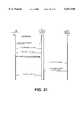
- FIG. 21illustrates how authentication operates in PPP/CHAP mode using a security server in accordance with an aspect of the present invention.
- FIG. 1is a block diagram illustrating one embodiment of a system for connecting telephone lines to a packet-switched network in accordance with an aspect of the present invention.
- Network access servers 100, 110 and 120connect to network 130.
- Network access server 100includes packet processor 102, line server 104, routing engine 108, and ports 105, 106 and 107.
- Packet processor 102connects to network 130 and relays data between line server 104 and network 130 under control of routing engine 108.
- Line server 104connects to ports 105, 106 and 107, through which line server 104 connects to telephone lines 140, 142 and 144, respectively.
- Telephone lines 140, 142 and 144connect to respective computer systems 150, 152 and 154.
- Network access server 100facilitates communication between computing systems 150, 152 and 154 and network 130. Communications from computing systems 150, 152 and 154 pass through ports 105, 106 and 107 into line server 104. Line server 104 routes these communications through packet processor 102 onto network 130 under control of routing engine 108.
- Network access server 110is structured similarly. It includes packet processor 112, line server 114, routing engine 118 and ports 115, 116 and 117. Ports 115, 116 and 117 connect to associated telephone lines which further connect to computing systems which are not shown.
- Network access server 120similarly includes packet processor 122, line server 124, routing engine 128 and ports 125, 126 and 127.
- Network access servers 100, 110 and 120communicate with each other through network 130.
- Network access server 100communicates with network access server 110 through communication channel 160, which passes through network 130.
- Network access server 110communicates with network access server 130 through communication channel 162, which passes through network 130.
- network access server 100communicates with network access server 120 through communication channel 164, which also passes through network 130.
- communication channels 160, 162 and 164do not pass through network 130, but rather pass through a separate communication network.
- Network 130is any type of packet-switched network, including local area networks as well as wide area networks such as the Internet.
- a computing systemsuch as computing system 150
- Line server 104communicates with packet processor 102 under control of routing engine 106.
- Packet processor 102handles the routing of data from computing system 150 onto network 130. This involves routing information amongst network access servers 100, 110 and 120 as well as across network 130.
- FIG. 2illustrates another embodiment of the present invention in which the packet processors are separate from the line servers.
- packet processors 200, 210 and 220connect to network 240.
- Separate line servers 250, 252 and 254also connect to network 240.
- Line server 250connects through telephone lines 260, 262 and 264 to computing systems 270, 272 and 274, respectively.
- Packet processor 200communicates with packet processor 210 through communication channel 282, which passes through network 240.
- Packet processor 210communicates with packet processor 220 through communication channel 284, which passes through network 240.
- Packet processor 200communicates with packet processor 220 through communication channel 280, which passes through network 240.
- communication channels 280, 282 and 284do not pass through network 240, but rather pass through a separate communication network.
- a computing systemsuch as computing system 270 communicates with line server 250 through telephone line 260.
- Line server 250handles communications with computing system 270 across telephone line 260, which includes handling modem scripts.
- Line server 250communicates with one of packet processors 200, 210 or 220 using a tunneling protocol.
- the associated packet processorhandles communications across network 240 to a remote host.
- FIG. 3illustrates the structure one embodiment of a packet processor in accordance with an aspect of the present invention.
- Local bus 302connects to CPU 300, boot ROM 304, flash memory 306, battery backup SRAM 308, console port UART 310 and DRAM 312.
- Local bus 302connects through interface 314 to system bus 322.
- System bus 322connects to Ethernet interface 316, token ring interface 318, IO card 324, IO card 326 and shared DRAM 328.
- Bus arbitrator 320controls operations on system bus 322.
- the peripheralsinclude: Ethernet interface 316, token ring interface 318, I/O card 324, and I/O card 326.
- These peripheralsare intelligent peripherals which can function as a bus master, a bus slave, or both.
- a peripheralresponds to read and write commands from CPU 300. This mode is typically employed by CPU 300 to configure the peripheral devices.
- the intelligent peripheralscan also function as a bus master. In this mode, they share the system bus under control of bus arbitrator 320.
- the intelligent peripherals connected to system bus 322communicate with CPU 300 through shared DRAM 328; they do not communicate with each other directly.
- FIG. 4is a block diagram illustrating some of the major functional components of the software architecture within a network access server or a packet processor in accordance with an aspect of the present invention.
- Level three componentsinclude: IP component 410, IPX component 412 and spoofing support component 414.
- Level two componentsinclude: PPP component 420, SLIP driver 434 and connection management component 422.
- level one componentsinclude: Ethernet driver 430, T1 driver 432 and ISDN driver 436.
- Kernel 400spans all three levels and contains the core software for supporting functions of the network access server.
- FIG. 5illustrates a number of possible data paths through the network access servers illustrated in FIG. 1.
- the network access servers in FIG. 1include an integrated packet processor and line server.
- a conventional data pathflows through a line server and an associated packet processor within the same network access server.
- the conventional data pathstarts at a port, flows through WAN driver 520, then through LCP (link layer control protocol)/authentication module 510, and then through bridging/routing NCP (network control protocol) module 500.
- LCPlink layer control protocol
- authentication module 510authentication module
- NCPnetwork control protocol
- Communicationsmay also flow between a line server in one network access server and a packet process server in another network access server.
- FIG. 1suppose computing system 150 communicates through telephone line 140 and port 105 with line server 104 within network access server 100.
- Line server 104could forward the communication through packet processor 112 within network access server 110, which would forward the communication to network 130.
- This type of connectionis illustrated by the pathway immediately to the right of the conventional data path. This pathway passes through WAN driver 520, LCP/authentication module 510 and LS module 540 before passing out of the network access server to a packet processor in a different network access server.
- a network access serverreceives a communication from a line server in another network access server and routes it through its local packet processor before forwarding it to the packet-switched network. This is illustrated by the data path which starts at the far right hand lower corner of FIG. 5, and passes through PP 530 and bridging/routing NCP 500, before connecting with a packet-switched network at the top of FIG. 5.
- FIG. 6illustrates the possible data pathways through a standalone packet processor such as packet processors 200, 210 and 220 in FIG. 2.
- FIG. 6illustrates a number of software modules.
- Bridging/routing NCP 600performs interface functions for communications with a packet-switched network, such as network 240 within FIG. 2.
- LCP/authentication modules 610 and 620perform link layer control protocol and authentication functions.
- PP module 630performs packet processor functions.
- LS module 640performs line server functions.
- WAN driver module 650controls communications through telephone line ports to remote computing systems.
- packet processorsinclude a plurality of WAN ports to accept such WAN inputs.
- a packet processorcan accept an input from a line server in another network access server. This is illustrated by the pathway starting immediately to the right of the lower-right-hand corner of WAN driver 650 in FIG. 6. This pathway passes through PP module 630, which performs link layer control protocol functions, and then through bridging/routing NCP module 600, before passing on to the network.
- a first pathwaypasses through PP Module 630, then through LCP/authentication module 620 and bridging/routing NCP module 600 before connecting with the network.
- the connection from a line servermay pass through PP module 630 and LCP/authentication module 620, before passing on to another packet processor to perform the bridging/routing NCP functions 600.
- FIG. 7illustrates the process of packet re-forwarding between network access server modules such as appear in FIG. 1.
- Network access server 700includes a number of software components including a plurality of logical ports 710, a plurality of local physical ports (LPPs) 740 and a plurality of remote physical ports (RPPs) 750.
- Logical ports 710contain data structures associated with logical connections to the computer network.
- Physical ports, including local physical ports 740 and remote physical ports 750,contain data structures associated with communications across telephone lines.
- Network access server 700also includes LS module 720 to perform line server functions, and PP module 730 to perform packet processor functions.
- Network access server 702includes a plurality of logical ports 712, a plurality of local physical ports 742, and a plurality of remote physical ports 752.
- Network access server 702additionally includes LS module 722 to perform line server functions, and PP module 732 to perform packet processor functions. Communications between network access server 700 and network access server 702 take place through PPTP tunnel 760.
- a number of eventsoccur during system initialization. For a single network access server operating in standalone mode, logical ports and physical ports are allocated during system initialization. When a client dials into the network access server across one of the telephone lines, a physical port is bound to a logical port.
- multiple PPTP sessionsare established between the multiple network access servers during system initialization.
- a client dials inits logical port might not be in the local network access server module. This can occur in several situations: (1) when a client dials in and requests free logical port and a free logical port does not exist; (2) when a spoofing client dials in and negotiates to reconnect or re-spoof, but the associated logical port is in the other network access server; and (3) when a multilink client with two channels dials into two separate network access servers, and the associated logical port for the client exists in only one of the network access servers. Under any of these circumstances, a local network access server re-forwards the data packets to the other network access server.
- the port mapping between local physical ports and remote physical portsis established through PPTP call handling procedures.
- FIG. 7illustrates both the conventional data path (dashed line) and the PPTP data path (solid line) through network access servers 700 and 702.
- a clientdials into network access server 702
- the incoming local physical portis bound, if possible, to a logical port within network access server 702, and data packets will follow the conventional data path, which is illustrated by the dotted line.
- the local physical portwill be marked as a PPTP port and data packets flowing through the local physical port will pass through PPTP tunnel 760 to network access server 700.
- itwill pass through one of the remote physical ports 750, and through PP 730, before ultimately passing into one of the logical ports 710 which connect to the network.
- FIG. 8illustrates packet re-forwarding within a packet processor, such as packet processors 200, 210 and 220 in FIG. 2.
- a packet processorsuch as packet processors 200, 210 and 220 in FIG. 2.
- communicationstypically flow through standalone line servers before flowing into a packet processor. If no logical ports are available at the packet processor, the packet processor attempts to re-forward the communication through another packet processor. This happens in cases of: load sharing, multilink communications and spoofing. Packet processors consequently have two types of remote physical ports.
- a local RPP (LRPP)for accepting communications directly from a standalone line server
- RRPPremote RPP
- Packet processor 800includes logical ports 802, local physical ports 820, local RPPS 830, remote RPPS 840, LS module 804 and PP module 806.
- Packet processor 810includes logical ports 812, local physical ports 822, local RPPS 832, remote RPPS 842, LS module 814 and PP module 816.
- Packet re-forwarding between packet processorsoperates as follows.
- a clientdials into a local RPP 832 in packet processor 810. This is illustrated by the solid and dashed lines entering local RPP 832 from the bottom of FIG. 8.
- Packet processor 810authenticates the client, and then attempts to allocate a logical port to the client within logical ports 812. If a logical port is found, the local RPP will be bound to the logical port and data packets will traverse the standard PPTP data path, illustrated by the dashed line. If the port is not found or is not available, the local RPP will be marked as a PP port.
- a local RPP within path processor 810makes a PPTP call to a remote RPP 840 within packet processor 800. All data packets from the line server to the local RPP are re-encapsulated with another header and sent along the solid line between local RPPS 832 within packet processor 810 and remote RPPS 840 within packet processor 800. This communication takes place through PPTP tunnel 850.
- FIG. 9is a table illustrating some of the major data structures associated with a physical port.
- Status data structure 910contains status information associated with the physical port. This includes up/down status and call-back status.
- Statistics data structure 920includes statistics about traffic through the physical port. This includes information on number of bytes, numbers of packets and error counts across the physical port.
- PPP table 930keeps track of PPP connections across the physical port.
- Driver table 940maintains information to support ISDN or asynchronous drivers for communications across the associated telephone line.
- Script data structure 950includes references to modem control scripts.
- Security table 960includes information used during the authentication process when a client dials into the associated physical port.
- PPTP table 970includes information on PPTP connections associated with the physical port.
- FIG. 10is a table containing some of the major data structures associated with a logical port.
- Status data structure 1010contains status information for the logical port.
- Statistics data structure 1020includes statistics on the usage of the associated logical port, including statistics such as numbers of packets and error counts.
- PPP table 1030maintains information to facilitate PPP connections through the logical port.
- Physical port data structure 1040includes references to physical ports associated with the logical port.
- Bandwidth data structure 1050includes information on the bandwidth utilization of the connection through the logical port.
- IP address data structure 1052includes the IP address for the logical port on the network.
- IPX address data structure 1053includes the IPX address of the logical port on the network.
- Spoofing data structure 1054includes data structures to support spoofing through the associated logical port.
- multilink data structure 1055includes data structures to facilitate multilink connections through the associated logical port.
- the present inventiondefines a set of messages, sent between network access servers or packet processors, including messages to verify whether a network access server has a free logical port or to check if a dialed local physical port is reserved for spoofing.
- the following messagesare used: a service request message to request that another network access server perform some type of service such as reporting a number of free logical ports, spoofing identification searches, multilink identification searches and searches for free/reserved physical ports; a service reply message to report the result of a service request; a pass LCP information message to transfer LCP information from line server to packet processor; a pass SLIP information message to transfer SLIP information from line server to packet processor, including the client's IP address and whether the client is running CSLIP; a pass user information message to pass user login related information from line server to packet processor; a port settled message from packet processor to line server to inform the line server that a remote physical port has been bound to a logical port and that frame re-forwarding can
- FIG. 11illustrates a number of possible connections through a system of multiple network access servers.
- Network access server 1100includes packet processor 1110 and line server 1120.
- Packet processor 1110includes logical ports 1130.
- Line server 1120includes local physical ports 1150 and remote physical ports 1160.
- Network access server 1102includes packet processor 1112 and line server 1122.
- Packet processor 1112includes logical ports 1132.
- Line server 1122includes local physical ports 1152 and remote physical ports 1162.
- a multilink client C 1170dials into network access server 1100 and network access server 1102 through channels C1 1172 and C2 1174, respectively.
- the frames sent through C2are re-forwarded to network access server 1100.
- the frames from C1 and C2are reassembled by the multilink module in network access server 1100 before routing through the network, as is illustrated by connection 1140.
- Network access serverssend messages to each other in order to determine whether another network access server has a free logical port, or if another network access server owns the logical port for an incoming call. Before sending these messages, the network access server first creates a node in a logical port search buffer (LPSB), so that search requests for the client can be tracked. The search reply information from other network access servers are stored in this LPSB so that a local network access server can determine which network access server it should forward the packets to.
- LPSBis used to support multilink identification searches, spoofing identification searches and searches for free logical ports and free/reserved physical ports.
- a network access serverreserves a physical port for each spoofed client so that clients can subsequently dial back in.
- the network access serverqueries physical port reservation status in local data structures as well as data structures in other network access servers and decides if the client may be spoofed.
- the network access servertries its best to avoid frame re-forwarding.
- FIG. 12illustrates a flowchart of the process for load sharing between network access servers in accordance with an aspect of the present invention.
- a network access serverstarts at state 1200, which is a start state. The server then proceeds to state 1204.
- the serverreceives a call from a telephone line on one of its ports.
- the systemthen proceeds to step 1206.
- the systemasks whether there is a free logical port within the network access server. If so, the system proceeds to step 1208. If not, the system proceeds to step 1210.
- the systemhas found a logical port within the network access server; it allocates the logical port and proceeds to step 1216 which is an end state.
- step 1210no free logical port exists in the local network access server, and the server requests a logical port from other network access servers.
- the systemthen proceeds to step 1212.
- step 1212the system receives a "port available" message from another network access server.
- step 1214not shown in the flowchart is the case where a "no port available" message is received by the network access server. In this case, after a certain timeout period, the call will fail because no logical port can be allocated to it.
- step 1214the call is routed through the other network access server so that the call uses a physical port in the local network access server and a logical port in the remote network access server.
- step 1216which is an end state.
- FIG. 13illustrates the process of establishing a multilink connection.
- the systemstarts at state 1300 which is a start state. It then proceeds state 1302.
- the systemreceives a request for a multilink connection.
- the systemproceeds to step 1304.
- the systemallocates a local logical port on the local system.
- the systemthen proceeds to step to 1306.
- the systemallocates as many local physical ports as possible to accommodate the multilink connection.
- the systemthen proceeds to step 1308.
- the systemallocates additional remote physical ports, as necessary, to accommodate all of the links in the multilink connection. This is accomplished by a series of communications with other network access servers or packet processors.
- the systemthen proceeds to step 1310 which is an end state.
- FIG. 14is a flowchart illustrating the operations of a network access server system or a packet processor system in implementing bandwidth-on-demand functions.
- the systemstarts at state 1400 which is a start state.
- the systemproceeds to state 1402, in which it monitors traffic on an existing multilink connection.
- the systemthen proceeds to step 1404.
- the systemasks whether the traffic is low on the multilink connection. If so, the system proceeds to step 1408. If not, the system proceeds to step 1406.
- the systemhas determined that the traffic on the multilink connection is low, and it tears down a link. In doing so, it first attempts to tear down a link through a remote physical port in order to eliminate unnecessary re-forwarding traffic.
- step 1412is an end state.
- the systemasks if the traffic through the multilink connection is high. If so, the system proceeds to step 1410. If not, the system proceeds to step 1412 which is an end state.
- the systemattempts to establish an additional link through a local physical port in order to prevent unnecessary communications across the network. If this is not possible, the system attempts to establish a link through a remote physical port. The system then proceeds to step 1412 which is an end state.
- FIG. 15illustrates the sequence of operations involved in spoofing at a network access server system or packet processor system in accordance with an aspect of the present invention.
- the systemstarts at step 1500 which is a start state. It then proceeds to step 1502, wherein the system monitors traffic on a pre-existing connection. It then proceeds to step 1504.
- the systemasks whether the connection has been "idle" for a significant period of time. "Idle” means either there is no traffic at all, or there has only been link maintenance traffic, such as keep alive packets, on the connection. If the link has been idle, the system proceeds to step 1506. If not, the system proceeds to step to 1514 which is an end state.
- step 1506the system has determined that the connection as been idle for a significant period of time and the system tears down the link. The system then proceeds to step 1508.
- step 1508the system monitors traffic through the link. The system then proceeds to step 1510.
- step 1510the system asks whether traffic through the link has been resumed. If not, the system proceeds to step 1514 which is an end state. If so, the system proceeds to step 1512.
- step 1512the system re-establishes the link for the multilink connection. The system then proceeds to step 1514 which is an end state.
- FIG. 16is a detailed flowchart illustrating the operations involved in performing load sharing across multiple network access servers or packet processors in accordance with an aspect of the present invention.
- the sequence of operations for load sharingis almost identical to the sequence of operations for packet re-forwarding to support multilink connections or to support spoofing across multiple network access servers or packet processors.
- FIG. 16illustrates operations for a local line server within a local network access server in the left-hand column, and operations for a remote packet processor in a remote network access server in the right-hand column.
- the systembegins at state 1600, in which a client dials in and the system answers the call.
- the systemnext proceeds to step 1601.
- the local line serverperforms authentication functions on the client before allowing it to connect to the local line server.
- the systemthen proceeds to step 1602.
- the systemgets information from the user.
- the systemnext proceeds to step 1603.
- the systemattempts to allocate a user data stream but fails.
- the systemnext proceeds to step 1604. Not shown on this flowchart is the case where the user successfully allocates a physical port in the local packet processor. In this case, the physical port is allocated to the data stream and the system proceeds to transmit data through the physical port.
- the local line serverhas failed to allocate a physical port in the local packet processor and it logs a port search request in the logical port search buffer (LPSB). It then sends a service request 1605 to the remote packet processor.
- the remote packet processorreceives the service request, checks whether free logical port and a local physical port are available. If a logical port and a local physical port are available, the remote packet processor sends a service reply 1607 to the local line server.
- the local line serverupdates the LPSB and removes the LPSB entry corresponding to the connection. The local line server then transmits an incoming call request 1609 to the remote packet processor.
- the remote packet processortransmits an incoming call reply 1611 back to the local line server.
- the local line serverhas completed the mapping.
- the local line serverthen transmits a message to the remote packet processor indicating that the incoming call is connected, and then passes information 1613 to the remote packet processor.
- This information 1613includes: information from the user, PPP information, SLIP information and authentication attributes.
- the remote packet processorallocates a logical port and binds the logical port.
- the remote packet processorthen transmits a port settled message 1615 to the local line server.
- the local line serverreceives the port settled message and starts the process of packet re-forwarding. The system then proceeds to step 1617 which is an end state.
- FIG. 17illustrates the sequence of operations involved in performing authentication in a system including two network access servers 1720 and 1730, and a security server 1710.
- the systemincludes network 1700 which is coupled to network access server 1730, network access server 1720, and security server 1710.
- network access server 1720Upon receiving a connection request from a user at network access server 1720, network access server 1720 first searches for the user's name in security tables in local physical ports at network access server 1720. This is illustrated by the dashed line labeled A. Next, if the user is not found within the local physical ports within network access server 1720, the system attempts to authenticate the user through security server 1710 across network 1700. This is indicated by the dashed line labeled B.
- network access server 1720exchanges messages across network 1700 with other network access servers to verify whether or not the same user has dialed into one of the other network access servers through another channel and has already been authenticated by security server 1710. This is indicated by the dashed line labeled B.
- the security tableis updated in the following way. During an internal search of the security table in the local physical port, if the user is not found the state is set to "waiting,” an authentication request is sent to the security server. If the user is found and the state is "idle,” the password authentication protocol (PAP) request is discarded. If the user is found and the state is "waiting,” the request is silently discarded. If the user is found and the state is "success,” the PAP request is acknowledged. If the user is found and the state is "failed,” the system sends an authentication query to another network access server. When an authentication reply is received from the security server and the reply indicates that the authentication request is accepted, the security table of the associated local physical port is set to a "success" value. When an authentication reply is received from the security server and the reply indicates that the authentication request is rejected, the security table of the associated local physical port is set to a "fail" value.
- PAPpassword authentication protocol
- FIG. 18illustrates the operation of the network access server in forwarding requests from the user interface and the security server without any challenges from the security server in accordance with an aspect of the present invention.
- Login client 1800first connects 1830 to network access server 1810.
- Network access server 1810then sends a login prompt 1831 to login client 1800.
- Login client 1800then sends a user name to 1832 to network access server 1810.
- Network access server 1810then sends a password prompt 1833 to login client 1800.
- Login client 1800then enters a password 1834 and sends it to network access server 1810.
- Network access serverbundles the user name and password together into an access request 1835 and sends this access request 1835 to security server 1820.
- Security server 1820processes this user name and password pair and sends either an access accept or access reject 1836 message back to network access server 1810.
- Network access server 1810then sends a login successful or login fail prompt 1837 to login client 1800. If network access server 1810 received an access reject message, the user interface goes through a retry process which is not shown.
- FIG. 19illustrates communications between login client 1900, network access server 1910 and security server 1920 during an authentication in user interface mode including an access challenge in accordance with an aspect of the present invention.
- login client 1900connects 1930 to network access server 1910.
- login client 1900 and network access server 1910engage in a sequence of login and password communications 1931, 1932, 1933 and 1934.
- network access server 1910bundles a user name and password into an access request 1935, and transmits this access request 1935 to security server 1920.
- Security server 1920then transmits an access challenge 1936 with a prompt to network access server 1910.
- Network access server 1910then transmits the prompt 1937 to login in client 1900.
- Login client 1900then enters the requested data 1938 and transmits it to network access server 1910.
- Network access server 1910then transmits the client data 1939 in an access request to security server 1920.
- Security server 1920then transmits an access accept or access reject message 1940 to network access server 1910.
- Network access server 1910then transmits a login successful or a fail message 1941 to login client 1900.
- Network access server 1910processes additional rounds of challenge and response as necessary for the authentication process.
- FIG. 20illustrates the sequence of operations involved in performing authentication between login client 2000, network access server 2010 and security server 2020, wherein login client 2000 communicates with network access server 2010 using a PPP protocol in accordance with an aspect of the present invention.
- login client 2000connects 2030 to network access server 2010.
- PPP negotiations 2031take place between login client 2000 and network access server 2010.
- login client 2000sends a user name and password to network access server 2010.
- Network access server 2010bundles the user name and password together and sends them in an access request 2033 to security server 2020.
- Security server 2020then sends either an access accept or access reject message 2034 to network access server 2010.
- Network access server 2010then sends a pass or fail message 2035 to login client 2000.
- This sequence of operationsis very similar to the sequence of operations in user interface mode. However, if security server 2020 sends a challenge, network access server 2010 has to fail the authentication, since PPP does not allow the login client to send additional information.
- FIG. 21illustrates a series of communications between login client 2100, network access server 2110 and security server 2120, wherein login client 2100 communicates with network access server 2110 through a PPP protocol using the challenge handshaking authentication protocol (CHAP) mode in accordance with an aspect of the present invention.
- Login client 2100first connects 2130 to network access server 2110.
- PPP negotiations 2131take place between login client 2100 and network access server 2110.
- network access server 2110next sends a CHAP challenge 2132 to login client 2100.
- Login client 2100then sends a user name and a CHAP response 2133 to network access server 2110.
- Network access server 2110bundles the CHAP challenge, user name and CHAP response into an access request 2134 and sends this access request 2134 to security server 2120.
- Security server 2120then computes the CHAP response with the CHAP challenge and the user password. If the result matches the CHAP response received, security server 2120 sends an access accept message 2135 to network access server 2110. Otherwise, it sends an access reject message 2135 to network access server 2110.
- Network access server 2110then sends a CHAP pass 2136 or a CHAP fail 2136 to login client 2100.
- the present inventionprovides an architecture which allows a plurality of network access servers or a plurality of packet processors to be connected together to form a single system for connecting a plurality of telephone lines to a packet-switched network.
- the inventionprovides scalability by allowing additional network access servers or packet processors to be connected to an existing system to expand capacity.
- the present inventionalso facilitates: load sharing between network access servers or packet processors; multilink connections across multiple network access servers or packet processors; and bandwidth on demand or spoofing across multiple network access servers or packet processors.
- the present inventionfacilitates authentication across multiple network access servers through a security server.
Landscapes
- Engineering & Computer Science (AREA)
- Computer Networks & Wireless Communication (AREA)
- Signal Processing (AREA)
- Computer Hardware Design (AREA)
- Computer Security & Cryptography (AREA)
- Computing Systems (AREA)
- General Engineering & Computer Science (AREA)
- Data Exchanges In Wide-Area Networks (AREA)
- Telephonic Communication Services (AREA)
Abstract
Description
Claims (17)
Priority Applications (3)
| Application Number | Priority Date | Filing Date | Title |
|---|---|---|---|
| US08/833,663US6011910A (en) | 1997-04-08 | 1997-04-08 | Supporting authentication across multiple network access servers |
| PCT/US1998/003516WO1998045785A2 (en) | 1997-04-08 | 1998-02-17 | Supporting authentication across multiple network access servers |
| AU66648/98AAU6664898A (en) | 1997-04-08 | 1998-02-17 | Supporting authentication across multiple network access servers |
Applications Claiming Priority (1)
| Application Number | Priority Date | Filing Date | Title |
|---|---|---|---|
| US08/833,663US6011910A (en) | 1997-04-08 | 1997-04-08 | Supporting authentication across multiple network access servers |
Publications (1)
| Publication Number | Publication Date |
|---|---|
| US6011910Atrue US6011910A (en) | 2000-01-04 |
Family
ID=25264973
Family Applications (1)
| Application Number | Title | Priority Date | Filing Date |
|---|---|---|---|
| US08/833,663Expired - LifetimeUS6011910A (en) | 1997-04-08 | 1997-04-08 | Supporting authentication across multiple network access servers |
Country Status (3)
| Country | Link |
|---|---|
| US (1) | US6011910A (en) |
| AU (1) | AU6664898A (en) |
| WO (1) | WO1998045785A2 (en) |
Cited By (125)
| Publication number | Priority date | Publication date | Assignee | Title |
|---|---|---|---|---|
| WO2000022790A1 (en)* | 1998-10-09 | 2000-04-20 | Asc - Advanced Switching Communications | Layer two tunneling protocol (l2tp) merging and management |
| US6147987A (en)* | 1997-04-08 | 2000-11-14 | 3Com Corporation | Supporting load sharing across multiple network access servers |
| US6205479B1 (en)* | 1998-04-14 | 2001-03-20 | Juno Online Services, Inc. | Two-tier authentication system where clients first authenticate with independent service providers and then automatically exchange messages with a client controller to gain network access |
| US6253327B1 (en) | 1998-12-02 | 2001-06-26 | Cisco Technology, Inc. | Single step network logon based on point to point protocol |
| US6263369B1 (en)* | 1998-10-30 | 2001-07-17 | Cisco Technology, Inc. | Distributed architecture allowing local user authentication and authorization |
| US6295356B1 (en) | 1998-03-26 | 2001-09-25 | Cisco Technology, Inc. | Power feed for network devices |
| US6298383B1 (en) | 1999-01-04 | 2001-10-02 | Cisco Technology, Inc. | Integration of authentication authorization and accounting service and proxy service |
| US6311275B1 (en) | 1998-08-03 | 2001-10-30 | Cisco Technology, Inc. | Method for providing single step log-on access to a differentiated computer network |
| US6324585B1 (en) | 1998-11-19 | 2001-11-27 | Cisco Technology, Inc. | Method and apparatus for domain name service request resolution |
| US6381646B2 (en) | 1998-11-03 | 2002-04-30 | Cisco Technology, Inc. | Multiple network connections from a single PPP link with partial network address translation |
| US6396833B1 (en) | 1998-12-02 | 2002-05-28 | Cisco Technology, Inc. | Per user and network routing tables |
| US6404736B1 (en)* | 1997-06-20 | 2002-06-11 | Telefonaktiebolaget L M Ericsson (Publ) | Call-routing efficiency with a network access server |
| US6412007B1 (en) | 1999-01-14 | 2002-06-25 | Cisco Technology, Inc. | Mechanism for authorizing a data communication session between a client and a server |
| US6412077B1 (en)* | 1999-01-14 | 2002-06-25 | Cisco Technology, Inc. | Disconnect policy for distributed computing systems |
| US6425003B1 (en) | 1999-01-22 | 2002-07-23 | Cisco Technology, Inc. | Method and apparatus for DNS resolution |
| US6430619B1 (en) | 1999-05-06 | 2002-08-06 | Cisco Technology, Inc. | Virtual private data network session count limitation |
| US6442608B1 (en) | 1999-01-14 | 2002-08-27 | Cisco Technology, Inc. | Distributed database system with authoritative node |
| US6466977B1 (en) | 1999-05-06 | 2002-10-15 | Cisco Technology, Inc. | Proxy on demand |
| US6467049B1 (en) | 1999-10-15 | 2002-10-15 | Cisco Technology, Inc. | Method and apparatus for configuration in multi processing engine computer systems |
| US6490289B1 (en) | 1998-11-03 | 2002-12-03 | Cisco Technology, Inc. | Multiple network connections from a single PPP link with network address translation |
| US6490290B1 (en) | 1998-12-30 | 2002-12-03 | Cisco Technology, Inc. | Default internet traffic and transparent passthrough |
| US20020188738A1 (en)* | 1999-11-29 | 2002-12-12 | Gray Robert H M | Data networks |
| US20020194294A1 (en)* | 1998-06-29 | 2002-12-19 | Blumenau Steven M. | Virtual ports for partitioning of data storage |
| US20020194327A1 (en)* | 2001-06-14 | 2002-12-19 | International Business Machines Corporation | Method for sensing the status of a client from a server |
| US20020194334A1 (en)* | 2001-06-14 | 2002-12-19 | Alcatel | Processor system, access server system, method and computer program product |
| US6502192B1 (en) | 1998-09-03 | 2002-12-31 | Cisco Technology, Inc. | Security between client and server in a computer network |
| US6529955B1 (en) | 1999-05-06 | 2003-03-04 | Cisco Technology, Inc. | Proxy session count limitation |
| US20030050962A1 (en)* | 1999-10-07 | 2003-03-13 | Robert Charles Monsen | Method and apparatus for securing information access |
| US6587468B1 (en) | 1999-02-10 | 2003-07-01 | Cisco Technology, Inc. | Reply to sender DHCP option |
| US6591304B1 (en) | 1999-06-21 | 2003-07-08 | Cisco Technology, Inc. | Dynamic, scaleable attribute filtering in a multi-protocol compatible network access environment |
| US20030153815A1 (en)* | 2002-02-08 | 2003-08-14 | Kenji Iwano | Medical information system |
| US6639577B2 (en) | 1998-03-04 | 2003-10-28 | Gemstar-Tv Guide International, Inc. | Portable information display device with ergonomic bezel |
| US20040062203A1 (en)* | 1998-04-10 | 2004-04-01 | Austermann John F. | System for communicating with electronic equipment |
| US6718467B1 (en) | 1999-10-28 | 2004-04-06 | Cisco Technology, Inc. | Password based protocol for secure communications |
| US6718376B1 (en) | 1998-12-15 | 2004-04-06 | Cisco Technology, Inc. | Managing recovery of service components and notification of service errors and failures |
| US6725264B1 (en) | 2000-02-17 | 2004-04-20 | Cisco Technology, Inc. | Apparatus and method for redirection of network management messages in a cluster of network devices |
| US6742126B1 (en) | 1999-10-07 | 2004-05-25 | Cisco Technology, Inc. | Method and apparatus for identifying a data communications session |
| US6751236B1 (en) | 2000-12-15 | 2004-06-15 | Cisco Technology, Inc. | Configurable channel associated signaling (“CAS”) line signaling using plain text strings |
| US6771665B1 (en) | 2000-08-31 | 2004-08-03 | Cisco Technology, Inc. | Matching of RADIUS request and response packets during high traffic volume |
| US6792457B1 (en) | 1998-10-13 | 2004-09-14 | Cisco Systems, Inc. | Multiple-level internet protocol accounting |
| US20040206683A1 (en)* | 2000-05-04 | 2004-10-21 | Cote Pierre Lucien | Immersed membrane apparatus |
| US6820115B1 (en)* | 1999-04-09 | 2004-11-16 | Nortel Networks Limited | Apparatus and method for mediating message transmission across a network |
| US6850980B1 (en) | 2000-06-16 | 2005-02-01 | Cisco Technology, Inc. | Content routing service protocol |
| US20050044390A1 (en)* | 1999-05-03 | 2005-02-24 | Cisco Technology, Inc., A California Corporation | Timing attacks against user logon and network I/O |
| US6871224B1 (en) | 1999-01-04 | 2005-03-22 | Cisco Technology, Inc. | Facility to transmit network management data to an umbrella management system |
| US20050083959A1 (en)* | 2001-07-05 | 2005-04-21 | Serconet, Ltd. | Telephone outlet with packet telephony adapter, and a network using same |
| US6895434B1 (en) | 2000-01-03 | 2005-05-17 | Cisco Technology, Inc. | Sharing of NAS information between PoPs |
| US6915289B1 (en)* | 2000-05-04 | 2005-07-05 | International Business Machines Corporation | Using an index to access a subject multi-dimensional database |
| US6918044B1 (en) | 1999-10-15 | 2005-07-12 | Cisco Technology, Inc. | Password protection for high reliability computer systems |
| US20050198500A1 (en)* | 2004-03-02 | 2005-09-08 | International Business Machines Corporation | System and method for performing security operations on network data |
| US20050198492A1 (en)* | 2004-03-02 | 2005-09-08 | International Business Machines Corporation. | System and method for secure data transfer over a network |
| US20050232299A1 (en)* | 2000-04-19 | 2005-10-20 | Serconet, Ltd. | Network combining wired and non-wired segments |
| US6966004B1 (en) | 1998-08-03 | 2005-11-15 | Cisco Technology, Inc. | Method for providing single step log-on access to a differentiated computer network |
| US20050268120A1 (en)* | 2004-05-13 | 2005-12-01 | Schindler Frederick R | Power delivery over ethernet cables |
| US6985935B1 (en) | 2000-12-20 | 2006-01-10 | Cisco Technology, Inc. | Method and system for providing network access to PPP clients |
| US6988148B1 (en) | 2001-01-19 | 2006-01-17 | Cisco Technology, Inc. | IP pool management utilizing an IP pool MIB |
| US7023879B1 (en) | 2001-03-09 | 2006-04-04 | Cisco Technology, Inc. | Dynamic multi-hop ingress to egress L2TP tunnel mapping |
| US20060072741A1 (en)* | 2003-01-30 | 2006-04-06 | Serconet Ltd | Method and system for providing DC power on local telephone lines |
| US7026730B1 (en) | 2002-12-20 | 2006-04-11 | Cisco Technology, Inc. | Integrated connector unit |
| US7047563B1 (en) | 2000-12-07 | 2006-05-16 | Cisco Technology, Inc. | Command authorization via RADIUS |
| US20060112288A1 (en)* | 2004-11-24 | 2006-05-25 | Schindler Frederick R | Increased power for power over ethernet applications |
| US7061142B1 (en) | 2003-05-28 | 2006-06-13 | Cisco Technology, Inc. | Inline power device detection |
| US20060143440A1 (en)* | 2004-12-27 | 2006-06-29 | Cisco Technology, Inc. | Using authentication server accounting to create a common security database |
| US20060149978A1 (en)* | 2005-01-04 | 2006-07-06 | Randall Anthony L | Method and system for managing power delivery for power over ethernet systems |
| US7099463B1 (en) | 2000-11-09 | 2006-08-29 | Cisco Technology, Inc. | Method and apparatus for detecting a compatible phantom powered device using common mode signaling |
| US20060203981A1 (en)* | 2000-03-20 | 2006-09-14 | Serconet Ltd. | Telephone outlet for implementing a local area network over telephone lines and a local area network using such outlets |
| US7139276B1 (en) | 2001-02-27 | 2006-11-21 | Cisco Technology, Inc. | Load sharing between L2TP tunnels |
| US7146422B1 (en) | 2000-05-01 | 2006-12-05 | Intel Corporation | Method and apparatus for validating documents based on a validation template |
| US7177947B1 (en) | 1999-01-22 | 2007-02-13 | Cisco Technology, Inc. | Method and apparatus for DNS resolution |
| US20070041340A1 (en)* | 2003-09-07 | 2007-02-22 | Serconet Ltd. | Modular outlet |
| US7197549B1 (en) | 2001-06-04 | 2007-03-27 | Cisco Technology, Inc. | On-demand address pools |
| US20070074292A1 (en)* | 2005-09-28 | 2007-03-29 | Hitachi, Ltd. | Management of encrypted storage networks |
| US20070208876A1 (en)* | 2002-05-06 | 2007-09-06 | Davis Ian E | Method and apparatus for efficiently processing data packets in a computer network |
| US7269786B1 (en) | 2000-05-04 | 2007-09-11 | International Business Machines Corporation | Navigating an index to access a subject multi-dimensional database |
| US7272649B1 (en) | 1999-09-30 | 2007-09-18 | Cisco Technology, Inc. | Automatic hardware failure detection and recovery for distributed max sessions server |
| US20070234054A1 (en)* | 2006-03-31 | 2007-10-04 | Alcatel | System and method of network equipment remote access authentication in a communications network |
| US20070234038A1 (en)* | 2004-12-13 | 2007-10-04 | Tao Jin | Method for Realizing the Synchronous Authentication Among the Different Authentication Control Devices |
| US20080005340A1 (en)* | 2006-06-15 | 2008-01-03 | Microsoft Corporation | Entering confidential information on an untrusted machine |
| US20080013529A1 (en)* | 2000-04-18 | 2008-01-17 | Serconet Ltd. | Telephone communication system over a single telephone line |
| US7325058B1 (en) | 2000-11-13 | 2008-01-29 | Cisco Technology, Inc. | Method and system for controlling subscriber access in a network capable of establishing connections with a plurality of domain sites |
| US7366297B1 (en) | 2003-05-21 | 2008-04-29 | Cisco Technology, Inc. | Method and system for converting alternating current to ethernet in-line power |
| US7370102B1 (en) | 1998-12-15 | 2008-05-06 | Cisco Technology, Inc. | Managing recovery of service components and notification of service errors and failures |
| US7389354B1 (en) | 2000-12-11 | 2008-06-17 | Cisco Technology, Inc. | Preventing HTTP server attacks |
| US20080181227A1 (en)* | 2007-01-31 | 2008-07-31 | Hewlett-Packard Development Company, L.P. | Zero-day security system |
| US7411981B1 (en) | 2000-08-31 | 2008-08-12 | Cisco Technology, Inc. | Matching of radius request and response packets during high traffic volume |
| US20080226060A1 (en)* | 2004-02-16 | 2008-09-18 | Serconet Ltd. | Outlet add-on module |
| US7443865B1 (en) | 2002-04-04 | 2008-10-28 | Cisco Technology, Inc. | Multiple network connections from a single PPP link with network address translation |
| US20080292073A1 (en)* | 1999-07-20 | 2008-11-27 | Serconet, Ltd | Network for telephony and data communication |
| US7472127B2 (en) | 2002-12-18 | 2008-12-30 | International Business Machines Corporation | Methods to identify related data in a multidimensional database |
| US7526533B1 (en) | 1999-11-30 | 2009-04-28 | Cisco Technology, Inc. | Active call context reconstruction for primary/backup resource manager servers |
| US7529832B2 (en) | 2000-11-13 | 2009-05-05 | Cisco Technology, Inc. | PPP domain name and L2TP tunnel selection configuration override |
| US20090129570A1 (en)* | 2004-01-13 | 2009-05-21 | Serconet, Ltd. | Information device |
| US20090185500A1 (en)* | 2008-01-17 | 2009-07-23 | Carl Steven Mower | Virtualization of networking services |
| US20090187970A1 (en)* | 2008-01-17 | 2009-07-23 | Carl Steven Mower | Networking as a service: delivering network services using remote appliances controlled via a hosted, multi-tenant management system |
| US20090190498A1 (en)* | 2008-01-17 | 2009-07-30 | Carl Steven Mower | Decomposition of networking device configuration into versioned pieces each conditionally applied depending on external circumstances |
| US20090282148A1 (en)* | 2007-07-18 | 2009-11-12 | Foundry Networks, Inc. | Segmented crc design in high speed networks |
| US20090279423A1 (en)* | 2006-11-22 | 2009-11-12 | Foundry Networks, Inc. | Recovering from Failures Without Impact on Data Traffic in a Shared Bus Architecture |
| US20090279549A1 (en)* | 2005-12-28 | 2009-11-12 | Foundry Networks, Inc. | Hitless software upgrades |
| US20090279546A1 (en)* | 2002-05-06 | 2009-11-12 | Ian Edward Davis | Flexible method for processing data packets in a network routing system for enhanced efficiency and monitoring capability |
| US20090279440A1 (en)* | 2007-01-11 | 2009-11-12 | Foundry Networks, Inc. | Techniques for processing incoming failure detection protocol packets |
| US20100046521A1 (en)* | 2003-05-15 | 2010-02-25 | Foundry Networks, Inc. | System and Method for High Speed Packet Transmission |
| US20100135313A1 (en)* | 2002-05-06 | 2010-06-03 | Foundry Networks, Inc. | Network routing system for enhanced efficiency and monitoring capability |
| US7746905B2 (en) | 2003-03-13 | 2010-06-29 | Mosaid Technologies Incorporated | Private telephone network connected to more than one public network |
| US20100185586A1 (en)* | 2003-06-30 | 2010-07-22 | Microsoft Corporation | Message-based scalable data transport protocol |
| US7788345B1 (en) | 2001-06-04 | 2010-08-31 | Cisco Technology, Inc. | Resource allocation and reclamation for on-demand address pools |
| US20100293327A1 (en)* | 2009-05-14 | 2010-11-18 | Brocade Communications Systems, Inc. | TCAM Management Approach That Minimize Movements |
| US20110002340A1 (en)* | 2002-05-06 | 2011-01-06 | Foundry Networks, Inc. | Pipeline method and system for switching packets |
| US20110044340A1 (en)* | 2006-08-22 | 2011-02-24 | Foundry Networks, Llc | System and method for ecmp load sharing |
| US7899918B1 (en) | 2003-10-10 | 2011-03-01 | Cisco Technology, Inc. | Service accounting in a network |
| US20110069711A1 (en)* | 2009-09-21 | 2011-03-24 | Brocade Communications Systems, Inc. | PROVISIONING SINGLE OR MULTISTAGE NETWORKS USING ETHERNET SERVICE INSTANCES (ESIs) |
| US20110110237A1 (en)* | 2004-03-26 | 2011-05-12 | Foundry Networks, Llc | Method and Apparatus for Aggregating Input Data Streams |
| US7965735B2 (en) | 1998-07-28 | 2011-06-21 | Mosaid Technologies Incorporated | Local area network of serial intelligent cells |
| US7990908B2 (en) | 2002-11-13 | 2011-08-02 | Mosaid Technologies Incorporated | Addressable outlet, and a network using the same |
| US8149839B1 (en) | 2007-09-26 | 2012-04-03 | Foundry Networks, Llc | Selection of trunk ports and paths using rotation |
| US20120331164A1 (en)* | 2010-03-09 | 2012-12-27 | Huawei Technologies Co. Ltd. | Load sharing method, system and access server |
| US8582598B2 (en) | 1999-07-07 | 2013-11-12 | Mosaid Technologies Incorporated | Local area network for distributing data communication, sensing and control signals |
| US8730961B1 (en) | 2004-04-26 | 2014-05-20 | Foundry Networks, Llc | System and method for optimizing router lookup |
| US8862773B2 (en) | 2000-04-13 | 2014-10-14 | Intel Corporation | Scalable network apparatus for content based switching or validation acceleration |
| US8880659B2 (en) | 2008-01-17 | 2014-11-04 | Aerohive Networks, Inc. | Configuring network devices using compilations of coherent subsections of configuration settings |
| US8898746B2 (en) | 1997-06-11 | 2014-11-25 | Prism Technologies Llc | Method for managing access to protected computer resources |
| US8934867B2 (en) | 2012-07-10 | 2015-01-13 | Symbol Technologies, Inc. | On-demand access tunnel between service provider network and wireless communication network |
| US8964754B2 (en) | 2000-11-17 | 2015-02-24 | Foundry Networks, Llc | Backplane interface adapter with error control and redundant fabric |
| US9935814B2 (en)* | 1997-06-19 | 2018-04-03 | My Mail Ltd. | Method of obtaining a network address |
| US10135878B2 (en) | 1997-06-19 | 2018-11-20 | Mymail, Ltd. | Method for accessing a digital network by way of one or more Internet service providers |
| US10228838B2 (en) | 1997-06-19 | 2019-03-12 | Mymail, Ltd. | Dynamically modifying a toolbar |
Families Citing this family (1)
| Publication number | Priority date | Publication date | Assignee | Title |
|---|---|---|---|---|
| US6785823B1 (en)* | 1999-12-03 | 2004-08-31 | Qualcomm Incorporated | Method and apparatus for authentication in a wireless telecommunications system |
Citations (9)
| Publication number | Priority date | Publication date | Assignee | Title |
|---|---|---|---|---|
| US4672572A (en)* | 1984-05-21 | 1987-06-09 | Gould Inc. | Protector system for computer access and use |
| US5495533A (en)* | 1994-04-29 | 1996-02-27 | International Business Machines Corporation | Personal key archive |
| US5560008A (en)* | 1989-05-15 | 1996-09-24 | International Business Machines Corporation | Remote authentication and authorization in a distributed data processing system |
| US5628005A (en)* | 1995-06-07 | 1997-05-06 | Microsoft Corporation | System and method for providing opportunistic file access in a network environment |
| US5649099A (en)* | 1993-06-04 | 1997-07-15 | Xerox Corporation | Method for delegating access rights through executable access control program without delegating access rights not in a specification to any intermediary nor comprising server security |
| US5652859A (en)* | 1995-08-17 | 1997-07-29 | Institute For The Development Of Emerging Architectures, L.L.C. | Method and apparatus for handling snoops in multiprocessor caches having internal buffer queues |
| US5659709A (en)* | 1994-10-03 | 1997-08-19 | Ast Research, Inc. | Write-back and snoop write-back buffer to prevent deadlock and to enhance performance in an in-order protocol multiprocessing bus |
| US5708780A (en)* | 1995-06-07 | 1998-01-13 | Open Market, Inc. | Internet server access control and monitoring systems |
| US5757916A (en)* | 1995-10-06 | 1998-05-26 | International Series Research, Inc. | Method and apparatus for authenticating the location of remote users of networked computing systems |
- 1997
- 1997-04-08USUS08/833,663patent/US6011910A/ennot_activeExpired - Lifetime
- 1998
- 1998-02-17AUAU66648/98Apatent/AU6664898A/ennot_activeAbandoned
- 1998-02-17WOPCT/US1998/003516patent/WO1998045785A2/enactiveApplication Filing
Patent Citations (9)
| Publication number | Priority date | Publication date | Assignee | Title |
|---|---|---|---|---|
| US4672572A (en)* | 1984-05-21 | 1987-06-09 | Gould Inc. | Protector system for computer access and use |
| US5560008A (en)* | 1989-05-15 | 1996-09-24 | International Business Machines Corporation | Remote authentication and authorization in a distributed data processing system |
| US5649099A (en)* | 1993-06-04 | 1997-07-15 | Xerox Corporation | Method for delegating access rights through executable access control program without delegating access rights not in a specification to any intermediary nor comprising server security |
| US5495533A (en)* | 1994-04-29 | 1996-02-27 | International Business Machines Corporation | Personal key archive |
| US5659709A (en)* | 1994-10-03 | 1997-08-19 | Ast Research, Inc. | Write-back and snoop write-back buffer to prevent deadlock and to enhance performance in an in-order protocol multiprocessing bus |
| US5628005A (en)* | 1995-06-07 | 1997-05-06 | Microsoft Corporation | System and method for providing opportunistic file access in a network environment |
| US5708780A (en)* | 1995-06-07 | 1998-01-13 | Open Market, Inc. | Internet server access control and monitoring systems |
| US5652859A (en)* | 1995-08-17 | 1997-07-29 | Institute For The Development Of Emerging Architectures, L.L.C. | Method and apparatus for handling snoops in multiprocessor caches having internal buffer queues |
| US5757916A (en)* | 1995-10-06 | 1998-05-26 | International Series Research, Inc. | Method and apparatus for authenticating the location of remote users of networked computing systems |
Cited By (260)
| Publication number | Priority date | Publication date | Assignee | Title |
|---|---|---|---|---|
| US6147987A (en)* | 1997-04-08 | 2000-11-14 | 3Com Corporation | Supporting load sharing across multiple network access servers |
| US8898746B2 (en) | 1997-06-11 | 2014-11-25 | Prism Technologies Llc | Method for managing access to protected computer resources |
| US9369469B2 (en) | 1997-06-11 | 2016-06-14 | Prism Technologies, L.L.C. | Method for managing access to protected computer resources |
| US9544314B2 (en) | 1997-06-11 | 2017-01-10 | Prism Technologies Llc | Method for managing access to protected computer resources |
| US9413768B1 (en) | 1997-06-11 | 2016-08-09 | Prism Technologies Llc | Method for managing access to protected computer resources |
| US10228838B2 (en) | 1997-06-19 | 2019-03-12 | Mymail, Ltd. | Dynamically modifying a toolbar |
| US10135878B2 (en) | 1997-06-19 | 2018-11-20 | Mymail, Ltd. | Method for accessing a digital network by way of one or more Internet service providers |
| US9935814B2 (en)* | 1997-06-19 | 2018-04-03 | My Mail Ltd. | Method of obtaining a network address |
| US6404736B1 (en)* | 1997-06-20 | 2002-06-11 | Telefonaktiebolaget L M Ericsson (Publ) | Call-routing efficiency with a network access server |
| US6639577B2 (en) | 1998-03-04 | 2003-10-28 | Gemstar-Tv Guide International, Inc. | Portable information display device with ergonomic bezel |
| US6295356B1 (en) | 1998-03-26 | 2001-09-25 | Cisco Technology, Inc. | Power feed for network devices |
| US20040062203A1 (en)* | 1998-04-10 | 2004-04-01 | Austermann John F. | System for communicating with electronic equipment |
| US8902760B2 (en) | 1998-04-10 | 2014-12-02 | Chrimar Systems, Inc. | Network system and optional tethers |
| US9019838B2 (en) | 1998-04-10 | 2015-04-28 | Chrimar Systems, Inc. | Central piece of network equipment |
| US8155012B2 (en) | 1998-04-10 | 2012-04-10 | Chrimar Systems, Inc. | System and method for adapting a piece of terminal equipment |
| US9049019B2 (en) | 1998-04-10 | 2015-06-02 | Chrimar Systems, Inc. | Network equipment and optional tether |
| US8942107B2 (en) | 1998-04-10 | 2015-01-27 | Chrimar Systems, Inc. | Piece of ethernet terminal equipment |
| US20090022057A1 (en)* | 1998-04-10 | 2009-01-22 | Austermann John F Iii | System and method for communicating with objects on a network |
| US9812825B2 (en) | 1998-04-10 | 2017-11-07 | Chrimar Systems, Inc. | Ethernet device |
| US6205479B1 (en)* | 1998-04-14 | 2001-03-20 | Juno Online Services, Inc. | Two-tier authentication system where clients first authenticate with independent service providers and then automatically exchange messages with a client controller to gain network access |
| US6988130B2 (en)* | 1998-06-29 | 2006-01-17 | Emc Corporation | Virtual ports for partitioning of data storage |
| US7051182B2 (en) | 1998-06-29 | 2006-05-23 | Emc Corporation | Mapping of hosts to logical storage units and data storage ports in a data processing system |
| US20040054866A1 (en)* | 1998-06-29 | 2004-03-18 | Blumenau Steven M. | Mapping of hosts to logical storage units and data storage ports in a data processing system |
| US20020194294A1 (en)* | 1998-06-29 | 2002-12-19 | Blumenau Steven M. | Virtual ports for partitioning of data storage |
| US8885660B2 (en) | 1998-07-28 | 2014-11-11 | Conversant Intellectual Property Management Incorporated | Local area network of serial intelligent cells |
| US7965735B2 (en) | 1998-07-28 | 2011-06-21 | Mosaid Technologies Incorporated | Local area network of serial intelligent cells |
| US8867523B2 (en) | 1998-07-28 | 2014-10-21 | Conversant Intellectual Property Management Incorporated | Local area network of serial intelligent cells |
| US8885659B2 (en) | 1998-07-28 | 2014-11-11 | Conversant Intellectual Property Management Incorporated | Local area network of serial intelligent cells |
| US8908673B2 (en) | 1998-07-28 | 2014-12-09 | Conversant Intellectual Property Management Incorporated | Local area network of serial intelligent cells |
| US8325636B2 (en) | 1998-07-28 | 2012-12-04 | Mosaid Technologies Incorporated | Local area network of serial intelligent cells |
| US7986708B2 (en) | 1998-07-28 | 2011-07-26 | Mosaid Technologies Incorporated | Local area network of serial intelligent cells |
| US6643782B1 (en) | 1998-08-03 | 2003-11-04 | Cisco Technology, Inc. | Method for providing single step log-on access to a differentiated computer network |
| US6311275B1 (en) | 1998-08-03 | 2001-10-30 | Cisco Technology, Inc. | Method for providing single step log-on access to a differentiated computer network |
| US6966004B1 (en) | 1998-08-03 | 2005-11-15 | Cisco Technology, Inc. | Method for providing single step log-on access to a differentiated computer network |
| US6502192B1 (en) | 1998-09-03 | 2002-12-31 | Cisco Technology, Inc. | Security between client and server in a computer network |
| US6094437A (en)* | 1998-10-09 | 2000-07-25 | Asc - Advanced Switching Communications | Layer two tunneling protocol (L2TP) merging and management |
| WO2000022790A1 (en)* | 1998-10-09 | 2000-04-20 | Asc - Advanced Switching Communications | Layer two tunneling protocol (l2tp) merging and management |
| US7346697B2 (en) | 1998-10-13 | 2008-03-18 | Cisco Technology, Inc. | Multiple-level internet protocol accounting |
| US20050044216A1 (en)* | 1998-10-13 | 2005-02-24 | Shujin Zhang | Multiple-level Internet protocol accounting |
| US6792457B1 (en) | 1998-10-13 | 2004-09-14 | Cisco Systems, Inc. | Multiple-level internet protocol accounting |
| US6263369B1 (en)* | 1998-10-30 | 2001-07-17 | Cisco Technology, Inc. | Distributed architecture allowing local user authentication and authorization |
| US6381646B2 (en) | 1998-11-03 | 2002-04-30 | Cisco Technology, Inc. | Multiple network connections from a single PPP link with partial network address translation |
| US6490289B1 (en) | 1998-11-03 | 2002-12-03 | Cisco Technology, Inc. | Multiple network connections from a single PPP link with network address translation |
| US6324585B1 (en) | 1998-11-19 | 2001-11-27 | Cisco Technology, Inc. | Method and apparatus for domain name service request resolution |
| US7036142B1 (en) | 1998-12-02 | 2006-04-25 | Cisco Technology, Inc. | Single step network logon based on point to point protocol |
| US6396833B1 (en) | 1998-12-02 | 2002-05-28 | Cisco Technology, Inc. | Per user and network routing tables |
| US7539194B1 (en) | 1998-12-02 | 2009-05-26 | Cisco Technology, Inc. | Per user and network routing tables |
| US6982978B1 (en) | 1998-12-02 | 2006-01-03 | Cisco Technology, Inc. | Per user and network routing tables |
| US6253327B1 (en) | 1998-12-02 | 2001-06-26 | Cisco Technology, Inc. | Single step network logon based on point to point protocol |
| US6718376B1 (en) | 1998-12-15 | 2004-04-06 | Cisco Technology, Inc. | Managing recovery of service components and notification of service errors and failures |
| US7370102B1 (en) | 1998-12-15 | 2008-05-06 | Cisco Technology, Inc. | Managing recovery of service components and notification of service errors and failures |
| US6490290B1 (en) | 1998-12-30 | 2002-12-03 | Cisco Technology, Inc. | Default internet traffic and transparent passthrough |
| US8077738B2 (en) | 1998-12-30 | 2011-12-13 | Cisco Technology, Inc. | Default internet traffic and transparent passthrough |
| US7420932B1 (en) | 1998-12-30 | 2008-09-02 | Cisco Technology, Inc. | Default internet traffic and transparent passthrough |
| US20080256620A1 (en)* | 1998-12-30 | 2008-10-16 | Cisco Technology, Inc. | Default Internet Traffic and Transparent Passthrough |
| US6871224B1 (en) | 1999-01-04 | 2005-03-22 | Cisco Technology, Inc. | Facility to transmit network management data to an umbrella management system |
| US7502851B1 (en) | 1999-01-04 | 2009-03-10 | Cisco Technology, Inc. | Facility to transmit network management data to an umbrella management system |
| US6298383B1 (en) | 1999-01-04 | 2001-10-02 | Cisco Technology, Inc. | Integration of authentication authorization and accounting service and proxy service |
| USRE41811E1 (en) | 1999-01-04 | 2010-10-05 | Cisco Technology, Inc. | Integration of authentication authorization and accounting service and proxy service |
| US6442608B1 (en) | 1999-01-14 | 2002-08-27 | Cisco Technology, Inc. | Distributed database system with authoritative node |
| US6412077B1 (en)* | 1999-01-14 | 2002-06-25 | Cisco Technology, Inc. | Disconnect policy for distributed computing systems |
| US6571287B1 (en) | 1999-01-14 | 2003-05-27 | Cisco Technology, Inc. | Distributed database system with authoritative node |
| US7028073B1 (en) | 1999-01-14 | 2006-04-11 | Cisco Technology, Inc. | Method and apparatus providing distributed authorization management of communication sessions |
| US6412007B1 (en) | 1999-01-14 | 2002-06-25 | Cisco Technology, Inc. | Mechanism for authorizing a data communication session between a client and a server |
| US6425003B1 (en) | 1999-01-22 | 2002-07-23 | Cisco Technology, Inc. | Method and apparatus for DNS resolution |
| US7177947B1 (en) | 1999-01-22 | 2007-02-13 | Cisco Technology, Inc. | Method and apparatus for DNS resolution |
| US6587468B1 (en) | 1999-02-10 | 2003-07-01 | Cisco Technology, Inc. | Reply to sender DHCP option |
| US6820115B1 (en)* | 1999-04-09 | 2004-11-16 | Nortel Networks Limited | Apparatus and method for mediating message transmission across a network |
| US20050044390A1 (en)* | 1999-05-03 | 2005-02-24 | Cisco Technology, Inc., A California Corporation | Timing attacks against user logon and network I/O |
| US7644439B2 (en) | 1999-05-03 | 2010-01-05 | Cisco Technology, Inc. | Timing attacks against user logon and network I/O |
| US7493395B2 (en) | 1999-05-06 | 2009-02-17 | Cisco Technology, Inc. | Virtual private data network session count limitation |
| US6816901B1 (en) | 1999-05-06 | 2004-11-09 | Cisco Technology, Inc. | Proxy session count limitation |
| US6910067B1 (en) | 1999-05-06 | 2005-06-21 | Cisco Technology, Inc. | Virtual private data network session count limitation |
| US6430619B1 (en) | 1999-05-06 | 2002-08-06 | Cisco Technology, Inc. | Virtual private data network session count limitation |
| US6466977B1 (en) | 1999-05-06 | 2002-10-15 | Cisco Technology, Inc. | Proxy on demand |
| US7606246B2 (en) | 1999-05-06 | 2009-10-20 | Cisco Technology, Inc. | Proxy on demand |
| US6529955B1 (en) | 1999-05-06 | 2003-03-04 | Cisco Technology, Inc. | Proxy session count limitation |
| US20060253896A1 (en)* | 1999-05-06 | 2006-11-09 | Cisco Technology, Inc. | Proxy on demand |
| US6591304B1 (en) | 1999-06-21 | 2003-07-08 | Cisco Technology, Inc. | Dynamic, scaleable attribute filtering in a multi-protocol compatible network access environment |
| US8582598B2 (en) | 1999-07-07 | 2013-11-12 | Mosaid Technologies Incorporated | Local area network for distributing data communication, sensing and control signals |
| US20080292073A1 (en)* | 1999-07-20 | 2008-11-27 | Serconet, Ltd | Network for telephony and data communication |
| US8929523B2 (en) | 1999-07-20 | 2015-01-06 | Conversant Intellectual Property Management Inc. | Network for telephony and data communication |
| US8351582B2 (en) | 1999-07-20 | 2013-01-08 | Mosaid Technologies Incorporated | Network for telephony and data communication |
| US8078715B2 (en) | 1999-09-30 | 2011-12-13 | Cisco Technology, Inc. | Automatic hardware failure detection and recovery for distributed max sessions server |
| US20110035496A1 (en)* | 1999-09-30 | 2011-02-10 | Cisco Technology, Inc., A California Corporation | Automatic hardware failure detection and recovery for distributed max sessions server |
| US7925732B2 (en) | 1999-09-30 | 2011-04-12 | Cisco Technology, Inc. | Automatic hardware failure detection and recovery for distributed max sessions server |
| US20080005328A1 (en)* | 1999-09-30 | 2008-01-03 | Cisco Technology, Inc. A California Corporation | Automatic hardware failure detection and recovery for distributed max sessions server |
| US7272649B1 (en) | 1999-09-30 | 2007-09-18 | Cisco Technology, Inc. | Automatic hardware failure detection and recovery for distributed max sessions server |
| US7043553B2 (en) | 1999-10-07 | 2006-05-09 | Cisco Technology, Inc. | Method and apparatus for securing information access |
| US20030050962A1 (en)* | 1999-10-07 | 2003-03-13 | Robert Charles Monsen | Method and apparatus for securing information access |
| US6742126B1 (en) | 1999-10-07 | 2004-05-25 | Cisco Technology, Inc. | Method and apparatus for identifying a data communications session |
| US6918044B1 (en) | 1999-10-15 | 2005-07-12 | Cisco Technology, Inc. | Password protection for high reliability computer systems |
| US6467049B1 (en) | 1999-10-15 | 2002-10-15 | Cisco Technology, Inc. | Method and apparatus for configuration in multi processing engine computer systems |
| US6718467B1 (en) | 1999-10-28 | 2004-04-06 | Cisco Technology, Inc. | Password based protocol for secure communications |
| US20020188738A1 (en)* | 1999-11-29 | 2002-12-12 | Gray Robert H M | Data networks |
| US7647403B2 (en)* | 1999-11-29 | 2010-01-12 | British Telecommunications Public Limited Company | Method for processing a request for access to a data network |
| US7526533B1 (en) | 1999-11-30 | 2009-04-28 | Cisco Technology, Inc. | Active call context reconstruction for primary/backup resource manager servers |
| US7529826B2 (en) | 2000-01-03 | 2009-05-05 | Cisco Technology, Inc. | Sharing of NAS information between PoPs |
| US6895434B1 (en) | 2000-01-03 | 2005-05-17 | Cisco Technology, Inc. | Sharing of NAS information between PoPs |
| US20050198294A1 (en)* | 2000-01-03 | 2005-09-08 | Cisco Technology, Inc., A California Corporation | Sharing of NAS information between PoPs |
| USRE41750E1 (en) | 2000-02-17 | 2010-09-21 | Cisco Technology, Inc. | Apparatus and method for redirection of network management messages in a cluster of network devices |
| US6725264B1 (en) | 2000-02-17 | 2004-04-20 | Cisco Technology, Inc. | Apparatus and method for redirection of network management messages in a cluster of network devices |
| US7715534B2 (en) | 2000-03-20 | 2010-05-11 | Mosaid Technologies Incorporated | Telephone outlet for implementing a local area network over telephone lines and a local area network using such outlets |
| US20060203981A1 (en)* | 2000-03-20 | 2006-09-14 | Serconet Ltd. | Telephone outlet for implementing a local area network over telephone lines and a local area network using such outlets |
| US8363797B2 (en) | 2000-03-20 | 2013-01-29 | Mosaid Technologies Incorporated | Telephone outlet for implementing a local area network over telephone lines and a local area network using such outlets |
| US8855277B2 (en) | 2000-03-20 | 2014-10-07 | Conversant Intellectual Property Managment Incorporated | Telephone outlet for implementing a local area network over telephone lines and a local area network using such outlets |
| US9712505B2 (en) | 2000-04-13 | 2017-07-18 | Intel Corporation | Scalable network apparatus for content based switching or validation acceleration |
| US9473411B2 (en) | 2000-04-13 | 2016-10-18 | Intel Corporation | Scalable network apparatus for content based switching or validation acceleration |
| US9369522B2 (en) | 2000-04-13 | 2016-06-14 | Intel Corporation | Scalable network apparatus for content based switching or validation acceleration |
| US8862773B2 (en) | 2000-04-13 | 2014-10-14 | Intel Corporation | Scalable network apparatus for content based switching or validation acceleration |
| US8223800B2 (en) | 2000-04-18 | 2012-07-17 | Mosaid Technologies Incorporated | Telephone communication system over a single telephone line |
| US8000349B2 (en) | 2000-04-18 | 2011-08-16 | Mosaid Technologies Incorporated | Telephone communication system over a single telephone line |
| US20080013529A1 (en)* | 2000-04-18 | 2008-01-17 | Serconet Ltd. | Telephone communication system over a single telephone line |
| US7593394B2 (en) | 2000-04-18 | 2009-09-22 | Mosaid Technologies Incorporated | Telephone communication system over a single telephone line |
| US8559422B2 (en) | 2000-04-18 | 2013-10-15 | Mosaid Technologies Incorporated | Telephone communication system over a single telephone line |
| US20080232579A1 (en)* | 2000-04-18 | 2008-09-25 | Serconet Ltd. | Telephone communication system over a single telephone line |
| US8867506B2 (en) | 2000-04-19 | 2014-10-21 | Conversant Intellectual Property Management Incorporated | Network combining wired and non-wired segments |
| US20100135479A1 (en)* | 2000-04-19 | 2010-06-03 | Mosaid Technologies Incorporated | Network combining wired and non-wired segments |
| US8982904B2 (en) | 2000-04-19 | 2015-03-17 | Conversant Intellectual Property Management Inc. | Network combining wired and non-wired segments |
| US20050232299A1 (en)* | 2000-04-19 | 2005-10-20 | Serconet, Ltd. | Network combining wired and non-wired segments |
| US8848725B2 (en) | 2000-04-19 | 2014-09-30 | Conversant Intellectual Property Management Incorporated | Network combining wired and non-wired segments |
| US8873586B2 (en) | 2000-04-19 | 2014-10-28 | Conversant Intellectual Property Management Incorporated | Network combining wired and non-wired segments |
| US8873575B2 (en) | 2000-04-19 | 2014-10-28 | Conversant Intellectual Property Management Incorporated | Network combining wired and non-wired segments |
| US8982903B2 (en) | 2000-04-19 | 2015-03-17 | Conversant Intellectual Property Management Inc. | Network combining wired and non-wired segments |
| US20100135480A1 (en)* | 2000-04-19 | 2010-06-03 | Mosaid Technologies Incorporated | Network combining wired and non-wired segments |
| US7633966B2 (en) | 2000-04-19 | 2009-12-15 | Mosaid Technologies Incorporated | Network combining wired and non-wired segments |
| US7146422B1 (en) | 2000-05-01 | 2006-12-05 | Intel Corporation | Method and apparatus for validating documents based on a validation template |
| US20040206683A1 (en)* | 2000-05-04 | 2004-10-21 | Cote Pierre Lucien | Immersed membrane apparatus |
| US6915289B1 (en)* | 2000-05-04 | 2005-07-05 | International Business Machines Corporation | Using an index to access a subject multi-dimensional database |
| US7269786B1 (en) | 2000-05-04 | 2007-09-11 | International Business Machines Corporation | Navigating an index to access a subject multi-dimensional database |
| US7529727B2 (en) | 2000-05-04 | 2009-05-05 | International Business Machines Corporation | Using an index to access a subject multi-dimensional database |
| US6850980B1 (en) | 2000-06-16 | 2005-02-01 | Cisco Technology, Inc. | Content routing service protocol |
| US7251681B1 (en) | 2000-06-16 | 2007-07-31 | Cisco Technology, Inc. | Content routing services protocol |
| US6771665B1 (en) | 2000-08-31 | 2004-08-03 | Cisco Technology, Inc. | Matching of RADIUS request and response packets during high traffic volume |
| US7411981B1 (en) | 2000-08-31 | 2008-08-12 | Cisco Technology, Inc. | Matching of radius request and response packets during high traffic volume |
| US7099463B1 (en) | 2000-11-09 | 2006-08-29 | Cisco Technology, Inc. | Method and apparatus for detecting a compatible phantom powered device using common mode signaling |
| US7325058B1 (en) | 2000-11-13 | 2008-01-29 | Cisco Technology, Inc. | Method and system for controlling subscriber access in a network capable of establishing connections with a plurality of domain sites |
| US7529832B2 (en) | 2000-11-13 | 2009-05-05 | Cisco Technology, Inc. | PPP domain name and L2TP tunnel selection configuration override |
| US8964754B2 (en) | 2000-11-17 | 2015-02-24 | Foundry Networks, Llc | Backplane interface adapter with error control and redundant fabric |
| US7047563B1 (en) | 2000-12-07 | 2006-05-16 | Cisco Technology, Inc. | Command authorization via RADIUS |
| US7389354B1 (en) | 2000-12-11 | 2008-06-17 | Cisco Technology, Inc. | Preventing HTTP server attacks |
| US6751236B1 (en) | 2000-12-15 | 2004-06-15 | Cisco Technology, Inc. | Configurable channel associated signaling (“CAS”) line signaling using plain text strings |
| US6985935B1 (en) | 2000-12-20 | 2006-01-10 | Cisco Technology, Inc. | Method and system for providing network access to PPP clients |
| US7587493B1 (en) | 2001-01-19 | 2009-09-08 | Cisco Technology, Inc. | Local network address management |
| US6988148B1 (en) | 2001-01-19 | 2006-01-17 | Cisco Technology, Inc. | IP pool management utilizing an IP pool MIB |
| US8321567B1 (en) | 2001-01-19 | 2012-11-27 | Cisco Technology, Inc. | IP pool management utilizing an IP pool MIB |
| US7139276B1 (en) | 2001-02-27 | 2006-11-21 | Cisco Technology, Inc. | Load sharing between L2TP tunnels |
| US7023879B1 (en) | 2001-03-09 | 2006-04-04 | Cisco Technology, Inc. | Dynamic multi-hop ingress to egress L2TP tunnel mapping |
| US7788345B1 (en) | 2001-06-04 | 2010-08-31 | Cisco Technology, Inc. | Resource allocation and reclamation for on-demand address pools |
| US7197549B1 (en) | 2001-06-04 | 2007-03-27 | Cisco Technology, Inc. | On-demand address pools |
| US20020194327A1 (en)* | 2001-06-14 | 2002-12-19 | International Business Machines Corporation | Method for sensing the status of a client from a server |
| US20020194334A1 (en)* | 2001-06-14 | 2002-12-19 | Alcatel | Processor system, access server system, method and computer program product |
| US7769030B2 (en) | 2001-07-05 | 2010-08-03 | Mosaid Technologies Incorporated | Telephone outlet with packet telephony adapter, and a network using same |
| US20050083959A1 (en)* | 2001-07-05 | 2005-04-21 | Serconet, Ltd. | Telephone outlet with packet telephony adapter, and a network using same |
| US8472593B2 (en) | 2001-07-05 | 2013-06-25 | Mosaid Technologies Incorporated | Telephone outlet with packet telephony adaptor, and a network using same |
| US8761186B2 (en) | 2001-07-05 | 2014-06-24 | Conversant Intellectual Property Management Incorporated | Telephone outlet with packet telephony adapter, and a network using same |
| US7680255B2 (en) | 2001-07-05 | 2010-03-16 | Mosaid Technologies Incorporated | Telephone outlet with packet telephony adaptor, and a network using same |
| US8150710B2 (en)* | 2002-02-08 | 2012-04-03 | Panasonic Corporation | Medical information system |
| US20030153815A1 (en)* | 2002-02-08 | 2003-08-14 | Kenji Iwano | Medical information system |
| US7443865B1 (en) | 2002-04-04 | 2008-10-28 | Cisco Technology, Inc. | Multiple network connections from a single PPP link with network address translation |
| US20110002340A1 (en)* | 2002-05-06 | 2011-01-06 | Foundry Networks, Inc. | Pipeline method and system for switching packets |
| US20070208876A1 (en)* | 2002-05-06 | 2007-09-06 | Davis Ian E | Method and apparatus for efficiently processing data packets in a computer network |
| US8194666B2 (en) | 2002-05-06 | 2012-06-05 | Foundry Networks, Llc | Flexible method for processing data packets in a network routing system for enhanced efficiency and monitoring capability |
| US8170044B2 (en) | 2002-05-06 | 2012-05-01 | Foundry Networks, Llc | Pipeline method and system for switching packets |
| US8989202B2 (en) | 2002-05-06 | 2015-03-24 | Foundry Networks, Llc | Pipeline method and system for switching packets |
| US20100135313A1 (en)* | 2002-05-06 | 2010-06-03 | Foundry Networks, Inc. | Network routing system for enhanced efficiency and monitoring capability |
| US20090279546A1 (en)* | 2002-05-06 | 2009-11-12 | Ian Edward Davis | Flexible method for processing data packets in a network routing system for enhanced efficiency and monitoring capability |
| US8671219B2 (en) | 2002-05-06 | 2014-03-11 | Foundry Networks, Llc | Method and apparatus for efficiently processing data packets in a computer network |
| US7990908B2 (en) | 2002-11-13 | 2011-08-02 | Mosaid Technologies Incorporated | Addressable outlet, and a network using the same |
| US20090063403A1 (en)* | 2002-12-18 | 2009-03-05 | International Business Machines Corporation | Systems and computer program products to identify related data in a multidimensional database |
| US7472127B2 (en) | 2002-12-18 | 2008-12-30 | International Business Machines Corporation | Methods to identify related data in a multidimensional database |
| US8126871B2 (en) | 2002-12-18 | 2012-02-28 | International Business Machines Corporation | Systems and computer program products to identify related data in a multidimensional database |
| US7026730B1 (en) | 2002-12-20 | 2006-04-11 | Cisco Technology, Inc. | Integrated connector unit |
| US7702095B2 (en) | 2003-01-30 | 2010-04-20 | Mosaid Technologies Incorporated | Method and system for providing DC power on local telephone lines |
| US8787562B2 (en) | 2003-01-30 | 2014-07-22 | Conversant Intellectual Property Management Inc. | Method and system for providing DC power on local telephone lines |
| US8107618B2 (en) | 2003-01-30 | 2012-01-31 | Mosaid Technologies Incorporated | Method and system for providing DC power on local telephone lines |
| US20060072741A1 (en)* | 2003-01-30 | 2006-04-06 | Serconet Ltd | Method and system for providing DC power on local telephone lines |
| US8238328B2 (en) | 2003-03-13 | 2012-08-07 | Mosaid Technologies Incorporated | Telephone system having multiple distinct sources and accessories therefor |
| US7746905B2 (en) | 2003-03-13 | 2010-06-29 | Mosaid Technologies Incorporated | Private telephone network connected to more than one public network |
| US8718051B2 (en) | 2003-05-15 | 2014-05-06 | Foundry Networks, Llc | System and method for high speed packet transmission |
| US9461940B2 (en) | 2003-05-15 | 2016-10-04 | Foundry Networks, Llc | System and method for high speed packet transmission |
| US20100046521A1 (en)* | 2003-05-15 | 2010-02-25 | Foundry Networks, Inc. | System and Method for High Speed Packet Transmission |
| US8811390B2 (en) | 2003-05-15 | 2014-08-19 | Foundry Networks, Llc | System and method for high speed packet transmission |
| US20100061393A1 (en)* | 2003-05-15 | 2010-03-11 | Foundry Networks, Inc. | System and Method for High Speed Packet Transmission |
| US7366297B1 (en) | 2003-05-21 | 2008-04-29 | Cisco Technology, Inc. | Method and system for converting alternating current to ethernet in-line power |
| US7061142B1 (en) | 2003-05-28 | 2006-06-13 | Cisco Technology, Inc. | Inline power device detection |
| US20100185586A1 (en)* | 2003-06-30 | 2010-07-22 | Microsoft Corporation | Message-based scalable data transport protocol |
| US20070041340A1 (en)* | 2003-09-07 | 2007-02-22 | Serconet Ltd. | Modular outlet |
| US7686653B2 (en) | 2003-09-07 | 2010-03-30 | Mosaid Technologies Incorporated | Modular outlet |
| US7899918B1 (en) | 2003-10-10 | 2011-03-01 | Cisco Technology, Inc. | Service accounting in a network |
| US20090129570A1 (en)* | 2004-01-13 | 2009-05-21 | Serconet, Ltd. | Information device |
| US20110016505A1 (en)* | 2004-01-13 | 2011-01-20 | May Patents Ltd. | Information device |
| US10986164B2 (en) | 2004-01-13 | 2021-04-20 | May Patents Ltd. | Information device |
| US11032353B2 (en) | 2004-01-13 | 2021-06-08 | May Patents Ltd. | Information device |
| US8611528B2 (en) | 2004-02-16 | 2013-12-17 | Mosaid Technologies Incorporated | Outlet add-on module |
| US20080226060A1 (en)* | 2004-02-16 | 2008-09-18 | Serconet Ltd. | Outlet add-on module |
| US7564976B2 (en) | 2004-03-02 | 2009-07-21 | International Business Machines Corporation | System and method for performing security operations on network data |
| US20050198492A1 (en)* | 2004-03-02 | 2005-09-08 | International Business Machines Corporation. | System and method for secure data transfer over a network |
| US8468337B2 (en) | 2004-03-02 | 2013-06-18 | International Business Machines Corporation | Secure data transfer over a network |
| US20050198500A1 (en)* | 2004-03-02 | 2005-09-08 | International Business Machines Corporation | System and method for performing security operations on network data |
| US8493988B2 (en) | 2004-03-26 | 2013-07-23 | Foundry Networks, Llc | Method and apparatus for aggregating input data streams |
| US20110110237A1 (en)* | 2004-03-26 | 2011-05-12 | Foundry Networks, Llc | Method and Apparatus for Aggregating Input Data Streams |
| US9338100B2 (en) | 2004-03-26 | 2016-05-10 | Foundry Networks, Llc | Method and apparatus for aggregating input data streams |
| US8730961B1 (en) | 2004-04-26 | 2014-05-20 | Foundry Networks, Llc | System and method for optimizing router lookup |
| US7603570B2 (en) | 2004-05-13 | 2009-10-13 | Cisco Technology, Inc. | Power delivery over ethernet cables |
| US20050268120A1 (en)* | 2004-05-13 | 2005-12-01 | Schindler Frederick R | Power delivery over ethernet cables |
| US7921314B2 (en) | 2004-05-13 | 2011-04-05 | Cisco Technology, Inc. | Providing power over ethernet cables |
| US7373528B2 (en) | 2004-11-24 | 2008-05-13 | Cisco Technology, Inc. | Increased power for power over Ethernet applications |
| US20060112288A1 (en)* | 2004-11-24 | 2006-05-25 | Schindler Frederick R | Increased power for power over ethernet applications |
| US8336082B2 (en)* | 2004-12-13 | 2012-12-18 | Huawei Technologies Co., Ltd. | Method for realizing the synchronous authentication among the different authentication control devices |
| US20070234038A1 (en)* | 2004-12-13 | 2007-10-04 | Tao Jin | Method for Realizing the Synchronous Authentication Among the Different Authentication Control Devices |
| US7861076B2 (en)* | 2004-12-27 | 2010-12-28 | Cisco Technology, Inc. | Using authentication server accounting to create a common security database |
| US20060143440A1 (en)* | 2004-12-27 | 2006-06-29 | Cisco Technology, Inc. | Using authentication server accounting to create a common security database |
| US7509505B2 (en) | 2005-01-04 | 2009-03-24 | Cisco Technology, Inc. | Method and system for managing power delivery for power over Ethernet systems |
| US20060149978A1 (en)* | 2005-01-04 | 2006-07-06 | Randall Anthony L | Method and system for managing power delivery for power over ethernet systems |
| US20080288794A1 (en)* | 2005-01-04 | 2008-11-20 | Cisco Technology, Inc. | Method and system for managing power delivery for power over ethernet systems |
| US8082457B2 (en) | 2005-01-04 | 2011-12-20 | Cisco Technology, Inc. | Data communications device for communicating with and concurrently providing power to a set of powerable devices |
| US20070074292A1 (en)* | 2005-09-28 | 2007-03-29 | Hitachi, Ltd. | Management of encrypted storage networks |
| US9378005B2 (en) | 2005-12-28 | 2016-06-28 | Foundry Networks, Llc | Hitless software upgrades |
| US20090279549A1 (en)* | 2005-12-28 | 2009-11-12 | Foundry Networks, Inc. | Hitless software upgrades |
| US8448162B2 (en)* | 2005-12-28 | 2013-05-21 | Foundry Networks, Llc | Hitless software upgrades |
| US20070234054A1 (en)* | 2006-03-31 | 2007-10-04 | Alcatel | System and method of network equipment remote access authentication in a communications network |
| US8966263B2 (en)* | 2006-03-31 | 2015-02-24 | Alcatel Lucent | System and method of network equipment remote access authentication in a communications network |
| US20080005340A1 (en)* | 2006-06-15 | 2008-01-03 | Microsoft Corporation | Entering confidential information on an untrusted machine |
| US8825728B2 (en)* | 2006-06-15 | 2014-09-02 | Microsoft Corporation | Entering confidential information on an untrusted machine |
| US20110044340A1 (en)* | 2006-08-22 | 2011-02-24 | Foundry Networks, Llc | System and method for ecmp load sharing |
| US8238255B2 (en) | 2006-11-22 | 2012-08-07 | Foundry Networks, Llc | Recovering from failures without impact on data traffic in a shared bus architecture |
| US9030943B2 (en) | 2006-11-22 | 2015-05-12 | Foundry Networks, Llc | Recovering from failures without impact on data traffic in a shared bus architecture |
| US20090279423A1 (en)* | 2006-11-22 | 2009-11-12 | Foundry Networks, Inc. | Recovering from Failures Without Impact on Data Traffic in a Shared Bus Architecture |
| US8395996B2 (en) | 2007-01-11 | 2013-03-12 | Foundry Networks, Llc | Techniques for processing incoming failure detection protocol packets |
| US20090279542A1 (en)* | 2007-01-11 | 2009-11-12 | Foundry Networks, Inc. | Techniques for using dual memory structures for processing failure detection protocol packets |
| US9112780B2 (en) | 2007-01-11 | 2015-08-18 | Foundry Networks, Llc | Techniques for processing incoming failure detection protocol packets |
| US20090279440A1 (en)* | 2007-01-11 | 2009-11-12 | Foundry Networks, Inc. | Techniques for processing incoming failure detection protocol packets |
| US8155011B2 (en) | 2007-01-11 | 2012-04-10 | Foundry Networks, Llc | Techniques for using dual memory structures for processing failure detection protocol packets |
| US20080181227A1 (en)* | 2007-01-31 | 2008-07-31 | Hewlett-Packard Development Company, L.P. | Zero-day security system |
| US9160759B2 (en) | 2007-01-31 | 2015-10-13 | Hewlett-Packard Development Company, L.P. | Security system for protecting networks from vulnerability exploits |
| US8391288B2 (en)* | 2007-01-31 | 2013-03-05 | Hewlett-Packard Development Company, L.P. | Security system for protecting networks from vulnerability exploits |
| US8271859B2 (en) | 2007-07-18 | 2012-09-18 | Foundry Networks Llc | Segmented CRC design in high speed networks |
| US20090282148A1 (en)* | 2007-07-18 | 2009-11-12 | Foundry Networks, Inc. | Segmented crc design in high speed networks |
| US8509236B2 (en) | 2007-09-26 | 2013-08-13 | Foundry Networks, Llc | Techniques for selecting paths and/or trunk ports for forwarding traffic flows |
| US8149839B1 (en) | 2007-09-26 | 2012-04-03 | Foundry Networks, Llc | Selection of trunk ports and paths using rotation |
| US8880659B2 (en) | 2008-01-17 | 2014-11-04 | Aerohive Networks, Inc. | Configuring network devices using compilations of coherent subsections of configuration settings |
| US20120331524A1 (en)* | 2008-01-17 | 2012-12-27 | Aerohive Networks, Inc. | Networking as a service |
| US20090187970A1 (en)* | 2008-01-17 | 2009-07-23 | Carl Steven Mower | Networking as a service: delivering network services using remote appliances controlled via a hosted, multi-tenant management system |
| US20090185500A1 (en)* | 2008-01-17 | 2009-07-23 | Carl Steven Mower | Virtualization of networking services |
| US20090190498A1 (en)* | 2008-01-17 | 2009-07-30 | Carl Steven Mower | Decomposition of networking device configuration into versioned pieces each conditionally applied depending on external circumstances |
| US8763084B2 (en)* | 2008-01-17 | 2014-06-24 | Aerohive Networks, Inc. | Networking as a service |
| US8347355B2 (en)* | 2008-01-17 | 2013-01-01 | Aerohive Networks, Inc. | Networking as a service: delivering network services using remote appliances controlled via a hosted, multi-tenant management system |
| US20140229587A1 (en)* | 2008-01-17 | 2014-08-14 | Aerohive Networks, Inc. | Networking as a service |
| US9762442B2 (en) | 2008-01-17 | 2017-09-12 | Aerohive Networks, Inc. | Virtualization of networking services |
| US9503354B2 (en) | 2008-01-17 | 2016-11-22 | Aerohive Networks, Inc. | Virtualization of networking services |
| US8259616B2 (en) | 2008-01-17 | 2012-09-04 | Aerohive Networks, Inc. | Decomposition of networking device configuration into versioned pieces each conditionally applied depending on external circumstances |
| US20100293327A1 (en)* | 2009-05-14 | 2010-11-18 | Brocade Communications Systems, Inc. | TCAM Management Approach That Minimize Movements |
| US8090901B2 (en) | 2009-05-14 | 2012-01-03 | Brocade Communications Systems, Inc. | TCAM management approach that minimize movements |
| US8599850B2 (en) | 2009-09-21 | 2013-12-03 | Brocade Communications Systems, Inc. | Provisioning single or multistage networks using ethernet service instances (ESIs) |
| US9166818B2 (en) | 2009-09-21 | 2015-10-20 | Brocade Communications Systems, Inc. | Provisioning single or multistage networks using ethernet service instances (ESIs) |
| US20110069711A1 (en)* | 2009-09-21 | 2011-03-24 | Brocade Communications Systems, Inc. | PROVISIONING SINGLE OR MULTISTAGE NETWORKS USING ETHERNET SERVICE INSTANCES (ESIs) |
| US8972593B2 (en)* | 2010-03-09 | 2015-03-03 | Huawei Technologies Co., Ltd. | Load sharing method, load sharing system and access server |
| US20120331164A1 (en)* | 2010-03-09 | 2012-12-27 | Huawei Technologies Co. Ltd. | Load sharing method, system and access server |
| US8934867B2 (en) | 2012-07-10 | 2015-01-13 | Symbol Technologies, Inc. | On-demand access tunnel between service provider network and wireless communication network |
Also Published As
| Publication number | Publication date |
|---|---|
| WO1998045785A3 (en) | 1999-01-07 |
| AU6664898A (en) | 1998-10-30 |
| WO1998045785A2 (en) | 1998-10-15 |
Similar Documents
| Publication | Publication Date | Title |
|---|---|---|
| US6011910A (en) | Supporting authentication across multiple network access servers | |
| US6147987A (en) | Supporting load sharing across multiple network access servers | |
| US6026085A (en) | Architecture to support a single system image across multiple network access servers | |
| US6906998B1 (en) | Switching device interfaces | |
| US5590328A (en) | Protocol parallel processing apparatus having a plurality of CPUs allocated to process hierarchical protocols | |
| US5835725A (en) | Dynamic address assignment and resolution technique | |
| US7640364B2 (en) | Port aggregation for network connections that are offloaded to network interface devices | |
| JP3746785B2 (en) | Network station with multiple network addresses | |
| US6278705B1 (en) | Integrated architecture to support a single system image across multiple network access servers | |
| JPH06243103A (en) | Parallel computer system | |
| JP2002531005A (en) | Method and apparatus for providing a guaranteed quality of service or class of service within and across a network using existing reservation protocols and frame formats | |
| US6233232B1 (en) | Supporting multilink connections across multiple network access servers | |
| US6760336B1 (en) | Flow detection scheme to support QoS flows between source and destination nodes | |
| US7350014B2 (en) | Connecting peer endpoints | |
| Gray | Network services in systems network architecture | |
| Cisco | Configuring APPN | |
| Cisco | Configuring APPN | |
| Cisco | Configuring APPN | |
| Cisco | Configuring APPN | |
| Cisco | Configuring APPN | |
| Cisco | Configuring APPN | |
| Cisco | Configuring APPN | |
| Cisco | Configuring Advanced Peer-to-Peer Networking | |
| Cisco | Configuring Advanced Peer-to-Peer Networking | |
| Cisco | Configuring Advanced Peer-to-Peer Networking |
Legal Events
| Date | Code | Title | Description |
|---|---|---|---|
| AS | Assignment | Owner name:3COM CORPORATION, CALIFORNIA Free format text:ASSIGNMENT OF ASSIGNORS INTEREST;ASSIGNORS:CHAU, WING C.;LEU, DARREN;LIU, TZE-JIAN;AND OTHERS;REEL/FRAME:008790/0321;SIGNING DATES FROM 19970612 TO 19970708 Owner name:3COM CORPORATION, CALIFORNIA Free format text:ASSIGNMENT OF ASSIGNORS INTEREST;ASSIGNOR:WANG, XIAOHU;REEL/FRAME:008790/0311 Effective date:19971001 Owner name:3COM CORPORATION, CALIFORNIA Free format text:ASSIGNMENT OF ASSIGNORS INTEREST;ASSIGNOR:PAO, JEFFREY K.;REEL/FRAME:008790/0368 Effective date:19971013 | |
| STCF | Information on status: patent grant | Free format text:PATENTED CASE | |
| AS | Assignment | Owner name:3COM CORPORATION, CALIFORNIA Free format text:MERGER;ASSIGNOR:3COM CORPORATION, A CORP. OF CALIFORNIA;REEL/FRAME:011195/0525 Effective date:19970611 | |
| FEPP | Fee payment procedure | Free format text:PAYOR NUMBER ASSIGNED (ORIGINAL EVENT CODE: ASPN); ENTITY STATUS OF PATENT OWNER: LARGE ENTITY Free format text:PAYER NUMBER DE-ASSIGNED (ORIGINAL EVENT CODE: RMPN); ENTITY STATUS OF PATENT OWNER: LARGE ENTITY | |
| FPAY | Fee payment | Year of fee payment:4 | |
| FPAY | Fee payment | Year of fee payment:8 | |
| FEPP | Fee payment procedure | Free format text:PAYOR NUMBER ASSIGNED (ORIGINAL EVENT CODE: ASPN); ENTITY STATUS OF PATENT OWNER: LARGE ENTITY Free format text:PAYER NUMBER DE-ASSIGNED (ORIGINAL EVENT CODE: RMPN); ENTITY STATUS OF PATENT OWNER: LARGE ENTITY | |
| AS | Assignment | Owner name:HEWLETT-PACKARD COMPANY, CALIFORNIA Free format text:MERGER;ASSIGNOR:3COM CORPORATION;REEL/FRAME:024630/0820 Effective date:20100428 | |
| AS | Assignment | Owner name:HEWLETT-PACKARD COMPANY, CALIFORNIA Free format text:CORRECTIVE ASSIGNMENT TO CORRECT THE SEE ATTACHED;ASSIGNOR:3COM CORPORATION;REEL/FRAME:025039/0844 Effective date:20100428 | |
| FPAY | Fee payment | Year of fee payment:12 | |
| AS | Assignment | Owner name:HEWLETT-PACKARD DEVELOPMENT COMPANY, L.P., TEXAS Free format text:ASSIGNMENT OF ASSIGNORS INTEREST;ASSIGNOR:HEWLETT-PACKARD COMPANY;REEL/FRAME:027329/0044 Effective date:20030131 | |
| AS | Assignment | Owner name:HEWLETT-PACKARD DEVELOPMENT COMPANY, L.P., TEXAS Free format text:CORRECTIVE ASSIGNMENT PREVIUOSLY RECORDED ON REEL 027329 FRAME 0001 AND 0044;ASSIGNOR:HEWLETT-PACKARD COMPANY;REEL/FRAME:028911/0846 Effective date:20111010 | |
| AS | Assignment | Owner name:HEWLETT PACKARD ENTERPRISE DEVELOPMENT LP, TEXAS Free format text:ASSIGNMENT OF ASSIGNORS INTEREST;ASSIGNOR:HEWLETT-PACKARD DEVELOPMENT COMPANY, L.P.;REEL/FRAME:037079/0001 Effective date:20151027 |