US6011511A - Satellite dish positioning system - Google Patents
Satellite dish positioning systemDownload PDFInfo
- Publication number
- US6011511A US6011511AUS08/745,932US74593296AUS6011511AUS 6011511 AUS6011511 AUS 6011511AUS 74593296 AUS74593296 AUS 74593296AUS 6011511 AUS6011511 AUS 6011511A
- Authority
- US
- United States
- Prior art keywords
- signal
- antenna
- satellite
- display
- strength
- Prior art date
- Legal status (The legal status is an assumption and is not a legal conclusion. Google has not performed a legal analysis and makes no representation as to the accuracy of the status listed.)
- Expired - Lifetime
Links
Images


Classifications
- H—ELECTRICITY
- H01—ELECTRIC ELEMENTS
- H01Q—ANTENNAS, i.e. RADIO AERIALS
- H01Q1/00—Details of, or arrangements associated with, antennas
- H01Q1/12—Supports; Mounting means
- H01Q1/125—Means for positioning
Definitions
- the present inventionis related to the field of satellite dish receivers, and more particularly, to the positioning and orienting of satellite dish receivers.
- the Digital Satellite Servicehas become increasingly popular among consumers, permitting viewers in sparsely populated or mountainous areas high quality access to television programs from around the world.
- residents of areas too distant from a ground transmitter to receive high quality television signalsresidents of areas where delivery of television signals by cable is impractical, and residents of mobile homes and recreational vehicles moving from one location to another, can receive television programs wherever they happen to be.
- Television transmitters operating in the DSS systemprovide coded digital signals via a satellite to receivers located within the field of view of the satellite.
- the satellite or satellites in the DSS systemretransmit a signal from one or more earth stations to a large number of receiving earth stations. Satellites in geo-stationary orbit, or a series of satellites passing through positions over the United States, can provide continuous television programming to viewers, anywhere in the country.
- DSS receiversgenerally are low-cost, simple to connect, small and easily transportable parabolic antennas that consumers mount on a residential rooftop or recreational vehicle.
- a viewerdetermines the defined elevation and azimuth angles from the antenna location to the satellite.
- the coarse directional angles to the satellite in the satellite's field of view from any point on the earthcan easily be determined by a customer setting up a receiver location. Once the angles are determined, the viewer points the antenna toward an approximate point in the sky in the neighborhood of the satellite, and begins the adjustment or "fiddling" process of moving the antenna in slight movements until the reception at the television is clear. In the case of a mobile receiver unit, this process must be repeated at each location.
- different viewerslive in different parts of the country, or can move from one place to another, assisting a typical consumer with correct and accurate pointing of an antenna toward a satellite has become a necessary element of the DSS system.
- the elevation and azimuth anglesare available for each longitude and latitude, as well as for each zip code.
- a dish installercan usually point the antenna in the general direction of the satellite.
- the antennamay still be difficult to position accurately, for a number of reasons. Fine angle discrimination is difficult, due to the measurement errors of determining one's precise longitude and latitude, the range of locations that may be within a zip code, and even mechanical bending of the structure supporting the antenna. Mechanical bending of the structure causes an error that is difficult to measure and correct, since it may introduce a roll component as well as an unmeasured azimuth and elevation angle.
- the viewermay also create orientation errors, for example by installing the antenna support structure on a roof that is not completely horizontal, or, if the antenna is mounted on a recreational vehicle, by parking on an uneven site. If the base of the antenna structure is not placed on a truly horizontal stable support, required elevation angles, such as "42 degrees above the horizontal", are exceedingly difficult to implement.
- the antennais generally coupled to a receiver via a cable.
- the receiverthen provides the signal to the television or other viewing monitor.
- the cable providedis long enough to allow the antenna and the receiver/television to be some distance apart.
- the viewersets the antenna in a selected location, directs the antenna toward the general orientation angles (azimuth and elevation) as reported for the location of the antenna.
- the viewermust then make minor adjustments to the antenna orientation, often by only fractions of a degree, to receive a clear video image. Unfortunately, the physical distance between the television and the antenna make this precision adjustment difficult.
- the televisionis remote, i.e. too far to see clearly, and the line of sight is generally interrupted by walls and other objects.
- the viewerhas three options for adjusting the finer gradations in the orientation of the antenna: he can make repeated trips between the antenna and the television; he can enlist the aid of another person to watch the television and report orally on how clearly the signal is being received, either by calling out loudly enough to hear or by using a two-way radio (i.e., a walkie-talkie); or the viewer can hire an installation service.
- the second solutionis not satisfactory either due to the difficulty in describing the clarity of a picture in measurable terms. Also, many people live alone or in remote areas, and one of the most important features of DSS is its ability to provide clear television pictures to remote areas too sparsely populated to attract cable companies. The third solution can be prohibitively expensive, and also may be unavailable to people living in remote areas.
- a commercially available system that attempts to resolve these problemsemploys a single blinking light at the antenna to indicate signal strength.
- the receiver connected to the antennaprovides a signal up the cable to the light at the antenna. This signal causes the light to blink slowly to indicate low received signal strength, and faster blinking to indicate higher signal strength.
- the antennais supposed to be positioned correctly.
- a method and apparatusare taught for positioning a satellite antenna to maximize the strength of the received satellite signal.
- a signal generatordetermining the strength of signals received from the antenna provides a strength signal to a display at a positionable antenna, where the display assists correct and accurate pointing of the antenna toward a satellite.
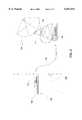
- FIG. 1is a schematic depiction of a DSS system in the installation environment.
- FIG. 2is a schematic depiction of the DSS system constructed in accordance with an embodiment of the present invention.
- a DSS systemis schematically depicted installed at a home.
- Structure 106is a home or private residence, an apartment building, a hotel, or a non-residential location such as a restaurant.
- a set-top box 102 serving as the signal receiveris located within the structure 106. The set-top box 102 receives the signal from an antenna 104 and conditions the signal for display by the television 108.
- the set-top box 102is coupled to the antenna 104 via a coaxial cable 110.
- the antenna 104is located exterior to the structure 106 to provide a clear line of sight to a satellite, and can be mounted on the structure 106 itself.
- the antenna 104transduces a radiated electromagnetic signal, received from a satellite in orbit about the earth, to a signal in the cable 110.
- the set-top box 102receives a number of frequency-multiplexed channels of television programming from the antenna 104 via coaxial cable 110, which extends from the interior of the structure 106 to the antenna 104.
- the set-top box 102contains a channel selector that is a demultiplexer for selecting a particular channel from the channels carried by the cable 110, the selected channel being presented on the television set 108 coupled to the set-top box 102.
- FIG. 2depicts a DSS system constructed in accordance with an exemplary embodiment of the present invention.
- the set-top box 102has an associated signal generator 112.
- the signal generator 112is within the same enclosure as the other components of the set-top box 102; and in other embodiments it is located external to the enclosure.
- the signal generator 112has a conventional signal strength detector that measures the overall signal strength of the signal from the antenna 104.
- the signal generator 112produces a coded signal indicative of the signal strength, and provides the coded signal over the cable 110 to the antenna 104.
- the coded signalis a low-frequency signal operating in a band not used for the primary signals from the antenna 104 to the set-top box 102. By using a different band for the coded reception strength signal, the embodiment can carry both the primary and the reception strength signals over the same cable.
- the signal generatortransmits a low frequency signal over the same cable 110 that carries the received signals from the antenna 104 to the set-top box 102
- the reception strength signalneed not be carried on the same medium as the transduced signal (e.g., video images).
- the coded reception strength signalgenerated by the signal generator 112, is provided to a display 116 located in the vicinity of the antenna 104.
- a low frequency signal receiver 118receives the low frequency reception strength signal.
- the low frequency signal receiver 118decodes the low frequency signal into a value that is presented on the display 116 collocated with the antenna site 114.
- the displayis located where it is visible to a person who is adjusting the antenna.
- the display 116is a multi-segment LED or LCD digital readouts.
- the display 116is a meter, having a needle pivoting at one end of the needle, sweeping out an angle corresponding to the signal strength.
- the display 116is a cross-hair video display 116 that directs the person adjusting the antenna 104 toward the proper alignment of an antenna 104 boresight with the transmitting satellite.
- the display 116includes a series of lights, each light having a unique threshold corresponding to a signal strength level, each light turning and remaining on when a numerical value indicated by the coded signal exceeds a threshold.
- the display 116 and the low frequency signal receiver 118can be integrated into one box.
- the reception signal strength informationis presented on a display in a manner that is readily interpretable by the antenna installer at the antenna mounting side.
- the displays of the different embodiments of the inventionprovide a quantifiable measure of the reception signal strength to the antenna installer. This permits the installer to make precise adjustments of the antenna positioning to maximize the reception signal strength.
- the low frequency signalis a balanced signal, i.e., a signal having no overall d.c. component.
- the low frequency signalemploys a balanced binary coding to encode a characteristic of the signal seen at the television, and provide information regarding the quality of the image to the display. Examples of balanced binary coding are presented in the following table; however, it will be apparent that the following examples are not limiting since any balanced code, and even more generally any code whether balanced or not, may be used in conjunction with the low frequency signal without departing from the present invention.
- An example of a suitable coding techniqueincludes NRZ (non-return to zero) coding.
- Balanced codingallows for the average d.c. component to remain zero over time.
- the low frequency signal propagating through the cable 110 from the signal generator 112does not interfere with the signal from the antenna 104 propagating to the set-top box 102, due to frequency separation.
- the value encoded in the low frequency signalis directly related to the signal strength of the DSS signal received at the set-top box 102.
- the low frequency signalis a digital value representing a percentage of the theoretical maximum signal strength the antenna 104 is able to receive.
- the low frequency signalis a digital value representing the power of the DSS signal received at the set-top box 102.
- the low frequency signalrepresents statistical correlation values between one video frame and the next.
- the signalis an analog signal proportional to the amplitude of the envelope (fundamental) of the DSS signal.
- Other representations of signal strength, power, statistical or stochastic correlation or coherence, or other indications of the quality of reception that might aid a person in pointing an antenna 104will be apparent to one skilled in the art upon reference to the present invention.
- the antenna installer at the site of the antennais able to precisely adjust the satellite dish receiver position since the installer has a quantifiable measure of the reception signal strength. Adjustment of the antenna position will either increase or decrease the displayed signal strength indication, as provided by the coded signal generated by the set-top box 102. The installer will then move the antenna in a precise manner to maximize the signal strength.
Landscapes
- Radio Relay Systems (AREA)
Abstract
Description
______________________________________digital value 4B/5B coding: 5B/6B coding ______________________________________ 0 000111 1 001011 2 001101 3 001110 4 010011 5 010101 6 010110 7 011001 8 011010 9 011100 10 100011 11 100101 12 100110 13 101001 14 101010 15 101100 16 110001 17 110010 18 110100 19 111000 ______________________________________
Claims (1)
Priority Applications (1)
| Application Number | Priority Date | Filing Date | Title |
|---|---|---|---|
| US08/745,932US6011511A (en) | 1996-11-07 | 1996-11-07 | Satellite dish positioning system |
Applications Claiming Priority (1)
| Application Number | Priority Date | Filing Date | Title |
|---|---|---|---|
| US08/745,932US6011511A (en) | 1996-11-07 | 1996-11-07 | Satellite dish positioning system |
Publications (1)
| Publication Number | Publication Date |
|---|---|
| US6011511Atrue US6011511A (en) | 2000-01-04 |
Family
ID=24998847
Family Applications (1)
| Application Number | Title | Priority Date | Filing Date |
|---|---|---|---|
| US08/745,932Expired - LifetimeUS6011511A (en) | 1996-11-07 | 1996-11-07 | Satellite dish positioning system |
Country Status (1)
| Country | Link |
|---|---|
| US (1) | US6011511A (en) |
Cited By (44)
| Publication number | Priority date | Publication date | Assignee | Title |
|---|---|---|---|---|
| US6216266B1 (en)* | 1999-10-28 | 2001-04-10 | Hughes Electronics Corporation | Remote control signal level meter |
| US20020083573A1 (en)* | 2000-12-29 | 2002-07-04 | Matz William R. | Antenna installation monitoring device and antenna installation methods |
| US6480207B1 (en)* | 1999-08-30 | 2002-11-12 | International Business Machines Corporation | Method, apparatus and computer program product for implementing graphical user interface (GUI) window control |
| US6509934B1 (en)* | 1998-12-22 | 2003-01-21 | Mitsubishi Electric Research Laboratories, Inc. | Directing an antenna to receive digital television signals |
| US20030061477A1 (en)* | 2001-09-21 | 2003-03-27 | Kahn Raynold M. | Method and apparatus for encrypting media programs for later purchase and viewing |
| US20030197809A1 (en)* | 1997-03-05 | 2003-10-23 | Greg Gangitano | Satellite signal loss on-screen notification |
| US6701528B1 (en) | 2000-01-26 | 2004-03-02 | Hughes Electronics Corporation | Virtual video on demand using multiple encrypted video segments |
| US20040102155A1 (en)* | 2002-11-21 | 2004-05-27 | Klauss Peter M. | Method and apparatus for minimizing conditional access information overhead while ensuring conditional access information reception in multi-tuner receivers |
| US20040102154A1 (en)* | 2002-11-21 | 2004-05-27 | Klauss Peter M. | Method and apparatus for ensuring reception of conditional access information in multi-tuner receivers |
| FR2850795A1 (en)* | 2003-01-30 | 2004-08-06 | Thomson Licensing Sa | Antenna alignment process for multimedia communication service, involves aligning antenna in center of curve described by high altitude platform, based on result of comparison between variation of residual power and threshold |
| US6853728B1 (en) | 2000-07-21 | 2005-02-08 | The Directv Group, Inc. | Video on demand pay per view services with unmodified conditional access functionality |
| US20050071866A1 (en)* | 2003-01-30 | 2005-03-31 | Ali Louzir | System for receiving broadcast digital data comprising a master digital terminal, and at least one slave digital terminal |
| US20050113032A1 (en)* | 2003-11-21 | 2005-05-26 | Franck Adam | Reception system including a pointing aid device |
| FR2862814A1 (en)* | 2003-11-21 | 2005-05-27 | Thomson Licensing Sa | Satellite TV reception system for use in satellite communication system, has pointing aid device to enable operator to receive antenna adjustment instructions and send end-of-adjustment information to indoor reception unit |
| EP1536510A1 (en)* | 2003-11-21 | 2005-06-01 | Thomson Licensing S.A. | Reception systen including a pointing aid device |
| US6906673B1 (en) | 2000-12-29 | 2005-06-14 | Bellsouth Intellectual Property Corporation | Methods for aligning an antenna with a satellite |
| US6937188B1 (en) | 2001-11-13 | 2005-08-30 | Bellsouth Intellectual Property Corporation | Satellite antenna installation tool |
| US20050249350A1 (en)* | 2004-05-04 | 2005-11-10 | Kahn Raynold M | Digital media conditional access system for handling digital media content |
| US6982745B2 (en)* | 2001-11-27 | 2006-01-03 | Sony Corporation | Antenna level display device and method, and receiving apparatus |
| US20060041903A1 (en)* | 2004-08-17 | 2006-02-23 | Kahn Raynold M | Service activation of set-top box functionality using broadcast conditional access system |
| US7039955B2 (en) | 2001-09-14 | 2006-05-02 | The Directv Group, Inc. | Embedded blacklisting for digital broadcast system security |
| US7102580B2 (en) | 2000-12-29 | 2006-09-05 | Bellsouth Intellectual Property Corp. | Antenna alignment devices |
| US20070036516A1 (en)* | 2005-08-11 | 2007-02-15 | The Directtv Group, Inc. | Secure delivery of program content via a removable storage medium |
| US7203314B1 (en) | 2000-07-21 | 2007-04-10 | The Directv Group, Inc. | Super encrypted storage and retrieval of media programs with modified conditional access functionality |
| US7203311B1 (en) | 2000-07-21 | 2007-04-10 | The Directv Group, Inc. | Super encrypted storage and retrieval of media programs in a hard-paired receiver and storage device |
| US20070118770A1 (en)* | 2000-07-21 | 2007-05-24 | Kahn Raynold M | Secure storage and replay of media programs using a hard-paired receiver and storage device |
| US20070242825A1 (en)* | 2004-01-16 | 2007-10-18 | Kahn Raynold M | Distribution of video content using a trusted network key for sharing content |
| US20070258596A1 (en)* | 2004-01-16 | 2007-11-08 | Kahn Raynold M | Distribution of broadcast content for remote decryption and viewing |
| US20070265966A1 (en)* | 2006-05-15 | 2007-11-15 | The Directv Group, Inc. | Content delivery systems and methods to operate the same |
| US20070266414A1 (en)* | 2006-05-15 | 2007-11-15 | The Directv Group, Inc. | Methods and apparatus to provide content on demand in content broadcast systems |
| US20070265967A1 (en)* | 2006-05-15 | 2007-11-15 | The Directv Group, Inc. | Methods and apparatus to conditionally authorize content delivery at broadcast headends in pay delivery systems |
| US20070265968A1 (en)* | 2006-05-15 | 2007-11-15 | The Directv Group, Inc. | Methods and apparatus to conditionally authorize content delivery at content servers in pay delivery systems |
| US20070265970A1 (en)* | 2006-05-15 | 2007-11-15 | The Directv Group, Inc. | Methods and apparatus to conditionally authorize content delivery at receivers in pay delivery systems |
| US20070265978A1 (en)* | 2006-05-15 | 2007-11-15 | The Directv Group, Inc. | Secure content transfer systems and methods to operate the same |
| US20070265973A1 (en)* | 2006-05-15 | 2007-11-15 | The Directv Group, Inc. | Methods and apparatus to protect content in home networks |
| US20080019529A1 (en)* | 2004-01-16 | 2008-01-24 | Kahn Raynold M | Distribution of video content using client to host pairing of integrated receivers/decoders |
| US7457414B1 (en) | 2000-07-21 | 2008-11-25 | The Directv Group, Inc. | Super encrypted storage and retrieval of media programs with smartcard generated keys |
| US20090207309A1 (en)* | 2008-02-15 | 2009-08-20 | Avermedia Technologies, Inc. | Digital Television Signal-Receiving Device with Signal Strength Showing Function |
| US7797552B2 (en) | 2001-09-21 | 2010-09-14 | The Directv Group, Inc. | Method and apparatus for controlling paired operation of a conditional access module and an integrated receiver and decoder |
| US7801303B2 (en) | 2004-03-01 | 2010-09-21 | The Directv Group, Inc. | Video on demand in a broadcast network |
| US8082572B1 (en) | 2000-06-08 | 2011-12-20 | The Directv Group, Inc. | Method and apparatus for transmitting, receiving, and utilizing audio/visual signals and other information |
| US9178693B2 (en) | 2006-08-04 | 2015-11-03 | The Directv Group, Inc. | Distributed media-protection systems and methods to operate the same |
| US9225761B2 (en) | 2006-08-04 | 2015-12-29 | The Directv Group, Inc. | Distributed media-aggregation systems and methods to operate the same |
| US12113605B2 (en)* | 2016-01-22 | 2024-10-08 | Viasat, Inc. | Determining an attenuation environment of a satellite communication terminal |
Citations (7)
| Publication number | Priority date | Publication date | Assignee | Title |
|---|---|---|---|---|
| US4167738A (en)* | 1977-06-27 | 1979-09-11 | Dennis Kirkendall | Antenna mounted tuning indicator |
| US4796032A (en)* | 1985-03-25 | 1989-01-03 | Kabushiki Kaisha Toshiba | Satellite broadcasting receiving system |
| US5376941A (en)* | 1992-10-30 | 1994-12-27 | Uniden Corporation | Antenna direction adjusting method and apparatus for satellite broadcasting receiving system |
| US5424750A (en)* | 1992-11-11 | 1995-06-13 | Dx Antenna Company, Limited | Stationary satellite signal receiving device |
| US5519405A (en)* | 1993-04-16 | 1996-05-21 | Masprodenkoh Kabushiki Kaisha | Direction adjustment indicator for a satellite radio wave receiving antenna |
| US5587717A (en)* | 1994-12-30 | 1996-12-24 | Hyundai Electronics Industries Co., Ltd. | Manual antenna alignment apparatus and method for very small aperture terminal |
| US5797083A (en)* | 1995-12-22 | 1998-08-18 | Hughes Electronics Corporation | Self-aligning satellite receiver antenna |
- 1996
- 1996-11-07USUS08/745,932patent/US6011511A/ennot_activeExpired - Lifetime
Patent Citations (7)
| Publication number | Priority date | Publication date | Assignee | Title |
|---|---|---|---|---|
| US4167738A (en)* | 1977-06-27 | 1979-09-11 | Dennis Kirkendall | Antenna mounted tuning indicator |
| US4796032A (en)* | 1985-03-25 | 1989-01-03 | Kabushiki Kaisha Toshiba | Satellite broadcasting receiving system |
| US5376941A (en)* | 1992-10-30 | 1994-12-27 | Uniden Corporation | Antenna direction adjusting method and apparatus for satellite broadcasting receiving system |
| US5424750A (en)* | 1992-11-11 | 1995-06-13 | Dx Antenna Company, Limited | Stationary satellite signal receiving device |
| US5519405A (en)* | 1993-04-16 | 1996-05-21 | Masprodenkoh Kabushiki Kaisha | Direction adjustment indicator for a satellite radio wave receiving antenna |
| US5587717A (en)* | 1994-12-30 | 1996-12-24 | Hyundai Electronics Industries Co., Ltd. | Manual antenna alignment apparatus and method for very small aperture terminal |
| US5797083A (en)* | 1995-12-22 | 1998-08-18 | Hughes Electronics Corporation | Self-aligning satellite receiver antenna |
Cited By (72)
| Publication number | Priority date | Publication date | Assignee | Title |
|---|---|---|---|---|
| US20030197809A1 (en)* | 1997-03-05 | 2003-10-23 | Greg Gangitano | Satellite signal loss on-screen notification |
| US6509934B1 (en)* | 1998-12-22 | 2003-01-21 | Mitsubishi Electric Research Laboratories, Inc. | Directing an antenna to receive digital television signals |
| US6480207B1 (en)* | 1999-08-30 | 2002-11-12 | International Business Machines Corporation | Method, apparatus and computer program product for implementing graphical user interface (GUI) window control |
| US6216266B1 (en)* | 1999-10-28 | 2001-04-10 | Hughes Electronics Corporation | Remote control signal level meter |
| US20040148634A1 (en)* | 2000-01-26 | 2004-07-29 | Hughes Electronics Corporation | Virtual video on demand using multiple encrypted video segments |
| US6701528B1 (en) | 2000-01-26 | 2004-03-02 | Hughes Electronics Corporation | Virtual video on demand using multiple encrypted video segments |
| US7926078B2 (en) | 2000-01-26 | 2011-04-12 | The Directv Group, Inc. | Virtual video on demand using multiple encrypted video segments |
| US8082572B1 (en) | 2000-06-08 | 2011-12-20 | The Directv Group, Inc. | Method and apparatus for transmitting, receiving, and utilizing audio/visual signals and other information |
| US7457414B1 (en) | 2000-07-21 | 2008-11-25 | The Directv Group, Inc. | Super encrypted storage and retrieval of media programs with smartcard generated keys |
| US7804958B2 (en) | 2000-07-21 | 2010-09-28 | The Directv Group, Inc. | Super encrypted storage and retrieval of media programs with smartcard generated keys |
| US7480381B2 (en) | 2000-07-21 | 2009-01-20 | The Directv Group, Inc. | Super encrypted storage and retrieval of media programs in a hard-paired receiver and storage device |
| US7203314B1 (en) | 2000-07-21 | 2007-04-10 | The Directv Group, Inc. | Super encrypted storage and retrieval of media programs with modified conditional access functionality |
| US7203311B1 (en) | 2000-07-21 | 2007-04-10 | The Directv Group, Inc. | Super encrypted storage and retrieval of media programs in a hard-paired receiver and storage device |
| US6853728B1 (en) | 2000-07-21 | 2005-02-08 | The Directv Group, Inc. | Video on demand pay per view services with unmodified conditional access functionality |
| US20070118770A1 (en)* | 2000-07-21 | 2007-05-24 | Kahn Raynold M | Secure storage and replay of media programs using a hard-paired receiver and storage device |
| US8140859B1 (en) | 2000-07-21 | 2012-03-20 | The Directv Group, Inc. | Secure storage and replay of media programs using a hard-paired receiver and storage device |
| US20070133795A1 (en)* | 2000-07-21 | 2007-06-14 | Kahn Raynold M | Super encrypted storage and retrieval of media programs in a hard-paired receiver and storage device |
| US20080313474A1 (en)* | 2000-07-21 | 2008-12-18 | The Directv Group, Inc. | Super encrypted storage and retrieval of media programs with smartcard generated keys |
| US6906673B1 (en) | 2000-12-29 | 2005-06-14 | Bellsouth Intellectual Property Corporation | Methods for aligning an antenna with a satellite |
| US6889421B1 (en)* | 2000-12-29 | 2005-05-10 | Bell South Intellectual Property Corp. | Antenna system installation and tuning method |
| US6799364B2 (en)* | 2000-12-29 | 2004-10-05 | Bellsouth Intellectual Property Corporation | Antenna aligning methods |
| US6789307B1 (en) | 2000-12-29 | 2004-09-14 | Bellsouth Intellectual Property Corporation | Methods for aligning an antenna with a satellite |
| US20020083573A1 (en)* | 2000-12-29 | 2002-07-04 | Matz William R. | Antenna installation monitoring device and antenna installation methods |
| US7102580B2 (en) | 2000-12-29 | 2006-09-05 | Bellsouth Intellectual Property Corp. | Antenna alignment devices |
| US7039955B2 (en) | 2001-09-14 | 2006-05-02 | The Directv Group, Inc. | Embedded blacklisting for digital broadcast system security |
| US7797552B2 (en) | 2001-09-21 | 2010-09-14 | The Directv Group, Inc. | Method and apparatus for controlling paired operation of a conditional access module and an integrated receiver and decoder |
| US7409562B2 (en) | 2001-09-21 | 2008-08-05 | The Directv Group, Inc. | Method and apparatus for encrypting media programs for later purchase and viewing |
| US20030061477A1 (en)* | 2001-09-21 | 2003-03-27 | Kahn Raynold M. | Method and apparatus for encrypting media programs for later purchase and viewing |
| US6937188B1 (en) | 2001-11-13 | 2005-08-30 | Bellsouth Intellectual Property Corporation | Satellite antenna installation tool |
| US6982745B2 (en)* | 2001-11-27 | 2006-01-03 | Sony Corporation | Antenna level display device and method, and receiving apparatus |
| US7000241B2 (en) | 2002-11-21 | 2006-02-14 | The Directv Group, Inc. | Method and apparatus for minimizing conditional access information overhead while ensuring conditional access information reception in multi-tuner receivers |
| US7225458B2 (en) | 2002-11-21 | 2007-05-29 | The Directv Group, Inc. | Method and apparatus for ensuring reception of conditional access information in multi-tuner receivers |
| US20040102154A1 (en)* | 2002-11-21 | 2004-05-27 | Klauss Peter M. | Method and apparatus for ensuring reception of conditional access information in multi-tuner receivers |
| US20040102155A1 (en)* | 2002-11-21 | 2004-05-27 | Klauss Peter M. | Method and apparatus for minimizing conditional access information overhead while ensuring conditional access information reception in multi-tuner receivers |
| EP1605542A1 (en)* | 2003-01-30 | 2005-12-14 | Thomson Licensing | Process for aligning at least one ground antenna with a platform flying at high altitude |
| US20050071866A1 (en)* | 2003-01-30 | 2005-03-31 | Ali Louzir | System for receiving broadcast digital data comprising a master digital terminal, and at least one slave digital terminal |
| FR2850795A1 (en)* | 2003-01-30 | 2004-08-06 | Thomson Licensing Sa | Antenna alignment process for multimedia communication service, involves aligning antenna in center of curve described by high altitude platform, based on result of comparison between variation of residual power and threshold |
| EP1536510A1 (en)* | 2003-11-21 | 2005-06-01 | Thomson Licensing S.A. | Reception systen including a pointing aid device |
| FR2862814A1 (en)* | 2003-11-21 | 2005-05-27 | Thomson Licensing Sa | Satellite TV reception system for use in satellite communication system, has pointing aid device to enable operator to receive antenna adjustment instructions and send end-of-adjustment information to indoor reception unit |
| US20050113032A1 (en)* | 2003-11-21 | 2005-05-26 | Franck Adam | Reception system including a pointing aid device |
| US7599494B2 (en) | 2004-01-16 | 2009-10-06 | The Directv Group, Inc. | Distribution of video content using a trusted network key for sharing content |
| US7548624B2 (en) | 2004-01-16 | 2009-06-16 | The Directv Group, Inc. | Distribution of broadcast content for remote decryption and viewing |
| US20080019529A1 (en)* | 2004-01-16 | 2008-01-24 | Kahn Raynold M | Distribution of video content using client to host pairing of integrated receivers/decoders |
| US20070242825A1 (en)* | 2004-01-16 | 2007-10-18 | Kahn Raynold M | Distribution of video content using a trusted network key for sharing content |
| US20070258596A1 (en)* | 2004-01-16 | 2007-11-08 | Kahn Raynold M | Distribution of broadcast content for remote decryption and viewing |
| US7580523B2 (en) | 2004-01-16 | 2009-08-25 | The Directv Group, Inc. | Distribution of video content using client to host pairing of integrated receivers/decoders |
| US7801303B2 (en) | 2004-03-01 | 2010-09-21 | The Directv Group, Inc. | Video on demand in a broadcast network |
| US20050249350A1 (en)* | 2004-05-04 | 2005-11-10 | Kahn Raynold M | Digital media conditional access system for handling digital media content |
| US7590243B2 (en) | 2004-05-04 | 2009-09-15 | The Directv Group, Inc. | Digital media conditional access system for handling digital media content |
| US7543317B2 (en) | 2004-08-17 | 2009-06-02 | The Directv Group, Inc. | Service activation of set-top box functionality using broadcast conditional access system |
| US20060041903A1 (en)* | 2004-08-17 | 2006-02-23 | Kahn Raynold M | Service activation of set-top box functionality using broadcast conditional access system |
| US8079043B2 (en) | 2004-08-17 | 2011-12-13 | The Directv Group, Inc. | Service activation of set-top box functionality using broadcast conditional access system |
| US20070036516A1 (en)* | 2005-08-11 | 2007-02-15 | The Directtv Group, Inc. | Secure delivery of program content via a removable storage medium |
| US9325944B2 (en) | 2005-08-11 | 2016-04-26 | The Directv Group, Inc. | Secure delivery of program content via a removable storage medium |
| US20070265968A1 (en)* | 2006-05-15 | 2007-11-15 | The Directv Group, Inc. | Methods and apparatus to conditionally authorize content delivery at content servers in pay delivery systems |
| US20070265973A1 (en)* | 2006-05-15 | 2007-11-15 | The Directv Group, Inc. | Methods and apparatus to protect content in home networks |
| US20070265970A1 (en)* | 2006-05-15 | 2007-11-15 | The Directv Group, Inc. | Methods and apparatus to conditionally authorize content delivery at receivers in pay delivery systems |
| US20070265967A1 (en)* | 2006-05-15 | 2007-11-15 | The Directv Group, Inc. | Methods and apparatus to conditionally authorize content delivery at broadcast headends in pay delivery systems |
| US7992175B2 (en) | 2006-05-15 | 2011-08-02 | The Directv Group, Inc. | Methods and apparatus to provide content on demand in content broadcast systems |
| US8001565B2 (en) | 2006-05-15 | 2011-08-16 | The Directv Group, Inc. | Methods and apparatus to conditionally authorize content delivery at receivers in pay delivery systems |
| US20070265966A1 (en)* | 2006-05-15 | 2007-11-15 | The Directv Group, Inc. | Content delivery systems and methods to operate the same |
| US20070266414A1 (en)* | 2006-05-15 | 2007-11-15 | The Directv Group, Inc. | Methods and apparatus to provide content on demand in content broadcast systems |
| US8095466B2 (en) | 2006-05-15 | 2012-01-10 | The Directv Group, Inc. | Methods and apparatus to conditionally authorize content delivery at content servers in pay delivery systems |
| US10977631B2 (en) | 2006-05-15 | 2021-04-13 | The Directv Group, Inc. | Secure content transfer systems and methods to operate the same |
| US8775319B2 (en) | 2006-05-15 | 2014-07-08 | The Directv Group, Inc. | Secure content transfer systems and methods to operate the same |
| US8996421B2 (en) | 2006-05-15 | 2015-03-31 | The Directv Group, Inc. | Methods and apparatus to conditionally authorize content delivery at broadcast headends in pay delivery systems |
| US9967521B2 (en) | 2006-05-15 | 2018-05-08 | The Directv Group, Inc. | Methods and apparatus to provide content on demand in content broadcast systems |
| US20070265978A1 (en)* | 2006-05-15 | 2007-11-15 | The Directv Group, Inc. | Secure content transfer systems and methods to operate the same |
| US9225761B2 (en) | 2006-08-04 | 2015-12-29 | The Directv Group, Inc. | Distributed media-aggregation systems and methods to operate the same |
| US9178693B2 (en) | 2006-08-04 | 2015-11-03 | The Directv Group, Inc. | Distributed media-protection systems and methods to operate the same |
| US20090207309A1 (en)* | 2008-02-15 | 2009-08-20 | Avermedia Technologies, Inc. | Digital Television Signal-Receiving Device with Signal Strength Showing Function |
| US12113605B2 (en)* | 2016-01-22 | 2024-10-08 | Viasat, Inc. | Determining an attenuation environment of a satellite communication terminal |
Similar Documents
| Publication | Publication Date | Title |
|---|---|---|
| US6011511A (en) | Satellite dish positioning system | |
| US6216266B1 (en) | Remote control signal level meter | |
| EP2580810B1 (en) | Antenna orientation determination | |
| US6795033B2 (en) | Antenna alignment devices | |
| US5983071A (en) | Video receiver with automatic satellite antenna orientation | |
| US6906673B1 (en) | Methods for aligning an antenna with a satellite | |
| US5797083A (en) | Self-aligning satellite receiver antenna | |
| US5903237A (en) | Antenna pointing aid | |
| CA2149695C (en) | Apparatus and method for aligning a receiving antenna utilizing an audible tone | |
| US5313215A (en) | Satellite identification and antenna alignment | |
| US6889421B1 (en) | Antenna system installation and tuning method | |
| US6753823B2 (en) | Antenna with integral alignment devices | |
| US7289062B2 (en) | Method and device for accurately pointing a satellite earth station antenna | |
| US6507325B2 (en) | Antenna alignment configuration | |
| US4689635A (en) | Apparatus for orientating TV antennas for satellite reception | |
| CA2287753A1 (en) | Method and apparatus for determining antenna pointing parameters in a satellite receiver | |
| EP1061677A2 (en) | Apparatus for mapping the geographic coverage of a broadcast signal | |
| KR20030023374A (en) | Antena of satellite broadcasting | |
| WO2019003043A1 (en) | Station, system and method for environmental monitoring of precipitation events | |
| US10181634B2 (en) | Outdoor unit configured for customer installation and method of aligning same | |
| KR19990067740A (en) | Remote satellite dish alignment aid | |
| GB2271669A (en) | Control of antennas | |
| Rezamand | CALIFORNIA STATE UNNERSITY, NORTHRIDGE | |
| KR20050021208A (en) | Method and apparatus for re-transmitting and distributing received broadcasting signals using wireless transmitter and wireless receiver | |
| KR19990060487A (en) | Satellite broadcasting antenna adjusting system and adjusting method |
Legal Events
| Date | Code | Title | Description |
|---|---|---|---|
| AS | Assignment | Owner name:SAMSUNG ELECTRONICS CO. LTD., KOREA, REPUBLIC OF Free format text:INVALID ASSIGNMENT;ASSIGNORS:CHUONG, BENSON;BARRY, CHARLES;REEL/FRAME:008438/0596 Effective date:19961031 | |
| AS | Assignment | Owner name:SAMSUNG ELECTRONICS CO., LTD., KOREA, REPUBLIC OF Free format text:ASSIGNMENT OF ASSIGNOR'S INTEREST AND INVENTOR'S NAME CORRECTION.;ASSIGNORS:CHUONG, BENSON;BARRY, CHARLES;REEL/FRAME:008415/0476;SIGNING DATES FROM 19970213 TO 19970214 | |
| STCF | Information on status: patent grant | Free format text:PATENTED CASE | |
| FEPP | Fee payment procedure | Free format text:PAYOR NUMBER ASSIGNED (ORIGINAL EVENT CODE: ASPN); ENTITY STATUS OF PATENT OWNER: LARGE ENTITY | |
| FPAY | Fee payment | Year of fee payment:4 | |
| FPAY | Fee payment | Year of fee payment:8 | |
| FEPP | Fee payment procedure | Free format text:PAYOR NUMBER ASSIGNED (ORIGINAL EVENT CODE: ASPN); ENTITY STATUS OF PATENT OWNER: LARGE ENTITY Free format text:PAYER NUMBER DE-ASSIGNED (ORIGINAL EVENT CODE: RMPN); ENTITY STATUS OF PATENT OWNER: LARGE ENTITY | |
| FPAY | Fee payment | Year of fee payment:12 |