US6011323A - Apparatus, method and article of manufacture providing for auxiliary battery conservation in adapters - Google Patents
Apparatus, method and article of manufacture providing for auxiliary battery conservation in adaptersDownload PDFInfo
- Publication number
- US6011323A US6011323AUS08/941,814US94181497AUS6011323AUS 6011323 AUS6011323 AUS 6011323AUS 94181497 AUS94181497 AUS 94181497AUS 6011323 AUS6011323 AUS 6011323A
- Authority
- US
- United States
- Prior art keywords
- power
- host
- interface
- adapter
- variable
- Prior art date
- Legal status (The legal status is an assumption and is not a legal conclusion. Google has not performed a legal analysis and makes no representation as to the accuracy of the status listed.)
- Expired - Lifetime
Links
- 238000000034methodMethods0.000titleclaimsabstractdescription14
- 238000004519manufacturing processMethods0.000titleclaimsabstract4
- 230000008878couplingEffects0.000claimsdescription11
- 238000010168coupling processMethods0.000claimsdescription11
- 238000005859coupling reactionMethods0.000claimsdescription11
- 230000003416augmentationEffects0.000claimsdescription5
- 230000001502supplementing effectEffects0.000claimsdescription3
- 230000003190augmentative effectEffects0.000claimsdescription2
- 230000006870functionEffects0.000description8
- 238000004891communicationMethods0.000description5
- 230000005540biological transmissionEffects0.000description4
- 230000001413cellular effectEffects0.000description3
- 239000013589supplementSubstances0.000description3
- 230000008901benefitEffects0.000description2
- 238000010586diagramMethods0.000description2
- 230000007246mechanismEffects0.000description2
- 238000012986modificationMethods0.000description2
- 230000004048modificationEffects0.000description2
- 238000012545processingMethods0.000description2
- 230000007812deficiencyEffects0.000description1
- 230000002950deficientEffects0.000description1
- 230000002045lasting effectEffects0.000description1
- 238000013507mappingMethods0.000description1
- 230000008569processEffects0.000description1
- 238000000926separation methodMethods0.000description1
- 238000001228spectrumMethods0.000description1
Images


Classifications
- H—ELECTRICITY
- H02—GENERATION; CONVERSION OR DISTRIBUTION OF ELECTRIC POWER
- H02J—CIRCUIT ARRANGEMENTS OR SYSTEMS FOR SUPPLYING OR DISTRIBUTING ELECTRIC POWER; SYSTEMS FOR STORING ELECTRIC ENERGY
- H02J7/00—Circuit arrangements for charging or depolarising batteries or for supplying loads from batteries
- H02J7/0063—Circuit arrangements for charging or depolarising batteries or for supplying loads from batteries with circuits adapted for supplying loads from the battery
- H—ELECTRICITY
- H02—GENERATION; CONVERSION OR DISTRIBUTION OF ELECTRIC POWER
- H02J—CIRCUIT ARRANGEMENTS OR SYSTEMS FOR SUPPLYING OR DISTRIBUTING ELECTRIC POWER; SYSTEMS FOR STORING ELECTRIC ENERGY
- H02J7/00—Circuit arrangements for charging or depolarising batteries or for supplying loads from batteries
- H02J7/007—Regulation of charging or discharging current or voltage
- H02J7/00712—Regulation of charging or discharging current or voltage the cycle being controlled or terminated in response to electric parameters
- H—ELECTRICITY
- H04—ELECTRIC COMMUNICATION TECHNIQUE
- H04W—WIRELESS COMMUNICATION NETWORKS
- H04W52/00—Power management, e.g. Transmission Power Control [TPC] or power classes
- H04W52/02—Power saving arrangements
- H04W52/0209—Power saving arrangements in terminal devices
- H04W52/0261—Power saving arrangements in terminal devices managing power supply demand, e.g. depending on battery level
- H04W52/0296—Power saving arrangements in terminal devices managing power supply demand, e.g. depending on battery level switching to a backup power supply
- H—ELECTRICITY
- H04—ELECTRIC COMMUNICATION TECHNIQUE
- H04B—TRANSMISSION
- H04B1/00—Details of transmission systems, not covered by a single one of groups H04B3/00 - H04B13/00; Details of transmission systems not characterised by the medium used for transmission
- H04B1/38—Transceivers, i.e. devices in which transmitter and receiver form a structural unit and in which at least one part is used for functions of transmitting and receiving
- H04B1/40—Circuits
- H04B1/54—Circuits using the same frequency for two directions of communication
- H04B1/56—Circuits using the same frequency for two directions of communication with provision for simultaneous communication in two directions
- Y—GENERAL TAGGING OF NEW TECHNOLOGICAL DEVELOPMENTS; GENERAL TAGGING OF CROSS-SECTIONAL TECHNOLOGIES SPANNING OVER SEVERAL SECTIONS OF THE IPC; TECHNICAL SUBJECTS COVERED BY FORMER USPC CROSS-REFERENCE ART COLLECTIONS [XRACs] AND DIGESTS
- Y02—TECHNOLOGIES OR APPLICATIONS FOR MITIGATION OR ADAPTATION AGAINST CLIMATE CHANGE
- Y02D—CLIMATE CHANGE MITIGATION TECHNOLOGIES IN INFORMATION AND COMMUNICATION TECHNOLOGIES [ICT], I.E. INFORMATION AND COMMUNICATION TECHNOLOGIES AIMING AT THE REDUCTION OF THEIR OWN ENERGY USE
- Y02D30/00—Reducing energy consumption in communication networks
- Y02D30/70—Reducing energy consumption in communication networks in wireless communication networks
Definitions
- the present inventionrelates to conservation of auxiliary battery power in adapters. More particularly, it relates to an apparatus and method for conserving auxiliary battery power in a wireless device that is connected to a host device.
- Wireless devicesenable computers to communicate with other computer devices without requiring physical access to a land line communication port.
- One type of wireless deviceis a wireless modem which is similar to a wired modem in that it permits a computer or other device to send and receive data from external sources.
- a wireless modemmay be installed as an adapter card or in an adapter slot such as a Personal Computer Memory Card International Association PCMCIA slot.
- a wireless modemtypically consists of two major portions: a radio portion and a baseband portion.
- the radio portionconsists of a transmitter and a receiver.
- the transmitter and receivermay share a common antenna via a duplexer.
- the transmitteris responsible for generating RF signals using a baseband signal to modulate a carrier signal.
- the receiveris responsible for producing a baseband signal from RF signals by demodulating an RF signal received at the antenna to produce a demodulated baseband signal.
- the radioprovides physical access to a network or connection (i.e., the wireless network).
- An antennais used for transmitting and receiving the electromagnetic communications signals from the air interface.
- the baseband portionprovides a baseband signal to the transmitter and accepts baseband signals from the radio receiver.
- the baseband portiondecodes the baseband signals to provide data (i.e., receiving data) and encodes data to provide a baseband signal for transmission by the transmitter (i.e., sending data).
- the adaptermay consist of an integrated package or several separate components that can be attached via appropriate cabling.
- the radio portion of the wireless adaptercontains the transmitter, receiver and associated circuitry to provide for RF communications.
- the ability of the radio to transmit at certain rangesis limited by the transmit power it can radiate via the antenna.
- the radio transmittercan require substantial amounts of current (as much as 1 amp) to operate. Most wireless systems require that the transmitter radiate power at levels up to 3 watts.
- the transmitted power levels in some wireless systemsare controlled by the base station transmitter.
- the radiated power levelcan thus require that approximately 1 amp of current be supplied to the radio transmitter of the wireless modem when the wireless modem is radiating at higher power levels.
- AMPSAdvanced Mobile Phone Service
- CDPDCellular Digital Packet Data
- ARDISAdvanced Radio Data Information Service
- the PCMCIA architecturecan typically only supply a PCMCIA slot with a 1/2 amp (500 mA) of current. This limitation is due to the nature of the PCMCIA interface and the PCMCIA standard itself. Therefore, with wireless adapters the PCMCIA bus of the host computer can supply less than half the required current when the radio transmitter is operating at higher power levels.
- prior art systemshave supplemented the power supplied to the radio with an auxiliary battery or batteries. These prior art systems have directly coupled the auxiliary power source to the transmit amplifier.
- the auxiliary batteryis inconvenient for mobile computer users to carry (i.e., 4AA NiCAD batteries). This inconvenience is caused by the bulk and weight of the auxiliary battery. The bulk of the auxiliary battery also makes the mobile device unwieldy to place and utilize. Secondly, the auxiliary battery needs to be periodically recharged. Auxiliary battery re-charging, in addition to any host battery recharging, is an inconvenience for user.
- the wireless adapter's recharging unitmay be incompatible with the recharging system for the laptop thus forcing the user to carry two different recharging mechanisms: one for the mobile unit's battery and one for the adapter's auxiliary battery.
- an adapter card for use in a host devicehaving an auxiliary power interface for receiving power from an auxiliary source; a host power interface for receiving host power signals; a power bus for distributing power on the adapter card, the power bus coupled to the host power interface; a switch for electrically coupling the host power interface or the auxiliary power interface to a variable power component; and, a controller for causing the switch to supply the variable power component with power from the auxiliary power interface when the power required by the variable power component exceeds a threshold, else causing the switch to supply the variable power component with received host power signals.
- Also provided is a method of conserving auxiliary batter power in an adapterhaving the steps of: determining a transmit power level and an associated power required by a power amplifier to yield a desired transmit power level; comparing the associated power required by the power amplifier with available power from a host interface; and supplying the power amplifier with power from an auxiliary source if the available power from a host interface is insufficient to meet the associated power required by the power amplifier.
- An adapter cardfor use in a host device, the adapter card having an auxiliary power interface for receiving power from an auxiliary source; a host power interface for receiving host power signals; a power bus for distributing power on the adapter card, the power bus coupled to the host power interface; and a power augmentation device for electrically coupling the host power interface to a variable power component and for augmenting power supplied to the variable power component from the host power interface with power supplied from the auxiliary power interface; and, a controller for causing the power augmentation device to augment power supplied to the variable power component with power from the auxiliary power interface when the power required by the variable power component exceeds the power that can be allocated to the variable power component from the host power interface.
- a method of conserving auxiliary battery powerhaving the following steps: determining a transmit power level and an associated power required by a power amplifier to yield a desired transmit power level; comparing the associated power required by the power amplifier with available power from a host power interface; and supplementing the power amplifier with power from an auxiliary source if the available power from the host power interface is insufficient to meet the associated power required by the power amplifier.
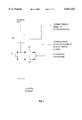
- FIG. 1is an overview of one embodiment of a wireless modem adapter.
- FIG. 2depicts a functional block diagram of a wireless modem adapter according to the present invention.
- FIG. 3depicts auxiliary battery use in a prior art configuration.
- FIG. 4depicts DC power management in accordance with the present invention.
- FIG. 5depicts a method of suppling power to the transmitter power amplifier in accordance with the present invention.
- FIG. 6depicts a switch version of the power control module.
- FIG. 7depicts a variable current version of the power control module.
- the present inventionwill be described with respect to a wireless radio adapter it is applicable to any adapter which supplements power from a host device with an auxiliary battery during normal operations.
- the present inventionreceives power from at least two sources: a host device and an auxiliary power source.
- the host devicemay be a laptop computer, such as an IBM Thinkpad computer, having one or more PCMCIA slots.
- HPMCIAPersonal Computer Memory Card International Association
- the host deviceprovides slots for accepting adapter cards. In the preferred embodiment these adapter cards and slots conform to Personal Computer Memory Card International Association (PCMCIA) standards.
- PCMCIAPersonal Computer Memory Card International Association
- the present inventionwill be described with respect to a constant or near constant voltage level, which for PCMCIA systems is +5 volts.
- a constant or near constant voltage levelwhich for PCMCIA systems is +5 volts.
- power which is typically measured in wattscan be represented by the current (amps) that a particular device or component is drawing. Therefore, current can be used to represent power.
- the present inventionis in no way limited to constant or near constant voltage systems.
- the wireless modemconsists of a PCMCIA adapter card 107 containing the baseband portion of the modem, a cable 105 for connecting the PCMCIA card to the radio module 101.
- the radio module 101is shown with antenna 111. Note that the radio module can be mounted on the host device such as the back of the display or integrated into the host device.
- the radio module 101is supplied power from the PCMCIA card via cable 105 and the auxiliary batteries contained within the housing 103.
- a 22 pin ITT connectoris used to connect the base band portion to the radio portion, although any suitable cable or electrical coupling may be utilized.
- the PCMCIA card 107contains a 68 pin PCMCIA standard connector that enables the card to be inserted into any PCMCIA adapter slot.
- the baseband adapter card and radio modulecan be integrated into a single card that can be inserted into a PCMCIA slot.
- the single integrated cardmay have a section that protrudes externally from the PCMCIA slot when the integrated card is inserted into the slot.
- cable 105carries signals between the radio module 101 and the baseband card 107. These signals provide the radio module 101 with power, control information, baseband signals for transmission and provides the baseband portion with status information and received baseband signals.
- FIG. 2depicts a functional block diagram of a wireless modem adapter according to the present invention.
- the wireless modem adapterinterfaces with the host device via the standard 68 pin PCMCIA connector and PCMCIA interface logic 203.
- the PCMCIA architecturepermits information to be written and read from the wireless modem adapter card.
- the PCMCIA interfaceis described in detail in the PCMCIA Specification (i.e., Personal Computer Memory Card International Association--PCMCIA Standard Release 2.1) which is hereby incorporated by reference.
- the PCMCIA interface logic 203may be combined with micro-controller 205 which may also be combined with DSP 207 into a single integrated circuit package.
- the adapter cardlooks to the PCMCIA bus as an I/O card type.
- the adapter cardreceives DC power from the PCMCIA interface and an auxiliary battery 209.
- the auxiliary battery 209may be mounted on the wireless modem adapter or may be external to the wireless modem adapter and coupled by a cable or other suitable connection or may be detachably mounted to the adapter card. DC power is distributed throughout the adapter using standard DC power distribution lines and techniques.
- a DC variable power controller 211can select one of two or more sources to provide variable power components with DC power. For instance, power consumption of the transmitter 217 (more specifically the transmit power amplifier) varies with the desired transmit power level.
- the transmittercan be supplied with DC power from the host device or the auxiliary source or both.
- the micro-controllercan signal or instruct the DC variable power controller 211 to provide the variable power component(s) with power from one of the power sources. This can be accomplished, for instance, by writing to a register or memory location assigned to the DC variable power controller 211.
- the DC variable power controller 211can select the source of DC power (i.e., the host device or the auxiliary battery) or may combine the two power sources to provide necessary power to the transmit power amplifier.
- the power received from the host deviceis distributed to all components of the wireless adapter with exception of one or more of the variable power consumption components such as the transmit power amplifier.
- Other components that have variable power characteristicsmay also be supplied power from the DC variable power controller on separate lines or share the same lines. Power management with multiple power components could provide none, one, or all of the variable power components with auxiliary power as power demand changed.
- the variable power componentsare supplied power via the DC variable power controller.
- the component that has the potential to draw the most current and use the most poweris the transmitter, specifically the transmit power amplifier.
- the transmitted power of each adaptercan be controlled by the base station. Transmitter power control by the base station allows the base station to better control the energy transmitted in the operating portion of the RF spectrum.
- the adapter's transmit powercan be lower than when the wireless adapter is operating in a fringe area or farther away from the base station.
- the adapter's transmit power outputis reduced, the current required by the RF power amplifier is reduced, often dramatically.
- the power required by the wireless adapteris less than the maximum power that the host device can supply. For instance, a PCMCIA slot can supply 500 ma of current.
- the wireless adaptercan take advantage of these time periods to conserve its auxiliary batteries by switching the auxiliary batteries off-line.
- the present inventionmakes use of the variable power consumption requirements of the wireless radio transmitter.
- the micro-controller 205instructs or causes the DC variable power controller 211 to provide the transmitter with power solely from the host device.
- the micro-controller 205instructs or causes the DC variable power controller 211 to supply the transmitter with power from the auxiliary source.
- One embodiment of the DC variable power controller 211is a single pole, double throw switch that is located between the auxiliary battery and the transmit power amplifier, so that the power amplifier can be powered alternatively by either the auxiliary battery or the host device through the PCMCIA interface.
- the switchis controlled by either a hardware or software threshold mechanism responding to a signal or determination that sets the transmit power output of the wireless adapter's transmitter. When the total expected power consumption for the wireless adapter exceeds the threshold then the auxiliary power is used to supply the transmitter's power amplifier else the host device supplies the power amp.
- the thresholdmay be computed in watts or amps. After determining the desired transmit power level, the current draw for the power amplifier can be determined based on known characteristics of the power amplifier.
- An algorithm or tablemay be used to provide transmitter current draw versus output power level.
- the thresholdis based on the maximum power/current that the host device can supply.
- the host devicesupplies the power to the entire wireless adapter including the variable power components. If the host device can supply 500 ma, of which 300 ma is used to power components other then the power amplifier, then 200 ma is available for the power amplifier. Thus, whenever the transmit power level requires the power amplifier to draw less or equal to 200 ma the auxiliary battery is not needed. Assuming an amplifier having a 50% efficiency rating operating at 5 volts, a PCMCIA slot can supply a transmit level up to 500 mw (200ma*5v*0.50).
- the auxiliary batteryis used to supply or supplement the power supplied to the transmit power amplifier.
- FIG. 3illustrates a depiction of a prior art system for supplying DC power to a prior art wireless adapter.
- the wireless adapter components, other than the transmit power amplifiertypically draw about 300 ma of current which is supplied by the PCMCIA adapter port.
- the auxiliary batteriesare directly coupled to the power amplifier and supply between 50 ma-450 ma of current. Note that the power amplifier is always drawing some current from the auxiliary batteries when the wireless adapter is powered up. Assuming operating characteristics as described in table I,
- a 1 hour transmit intervalrequires a battery with a 223 ma per hour capacity.
- FIG. 4illustrates the present invention wherein the DC variable power controller 405 is programmed or instructed to supply DC power to the transmit power amplifier when the transmit power level is greater than 250 mw and to use power from the host device when the transmit power is 250 mw or less.
- Adapter componentsother than the transmit power amplifier typically draw about 300 ma of current which is supplied by the PCMCIA adapter slot.
- the auxiliary batteriessupply 450 ma of current to the transmit power amplifier only when the output power level is 600 mw. Note that the power amplifier is not drawing any current from the auxiliary batteries when the transmit power levels are at the 250 mw and 100 mw levels. This situation is illustrated
- a 1 hour transmit intervalrequires a battery with only a 68 ma per hour capacity.
- the present inventionpermits the use of a smaller auxiliary battery or a greater time between re-charging or a combination of both. Also the present invention still permits the adapter to operate in low power mode when the auxiliary battery is unavailable. By reducing the auxiliary power consumed by the adapter card, a longer lasting power supply or smaller sized power supply can be utilized. Also with the present invention, the wireless adapter card can still function in low power mode when the auxiliary battery is dead or needs recharging or is in the process of recharging.
- FIG. 5depicts the method of the present invention.
- the adapterdetermines the required transmit power level. In the preferred embodiment this is accomplished by the micro-controller carrying out an appropriate software routine.
- the required transmit power levelmay be received from the base station in a message or it may be calculated by the micro-controller using a protocol or it may be read from storage or some other means. Even though some wireless systems fix the transmit power level, most wireless modems can support various wireless systems so that although auxiliary power cannot be conserved for all wireless systems, the present invention can conserve power with respect to some. From the required transmit power level, and known characteristics of the power amplifier and wireless adapter card the required current for the power amplifier can be calculated. Alternatively a table can used to relate transmit power level to the controller state. This is shown as step 503.
- a checkis made to determine whether the required current level for the power amplifier exceeds the power level that host device can supply. For example, if the adapter card is a PCMCIA adapter card and requires 300 ma of current, excluding the power amplifier then if the power amplifier requires a current of 200 ma or less the PCMCIA host device can supply the current necessary to power the amplifier without the auxiliary battery as shown in step 509. If the power amplifier requires more than 200 ma then the auxiliary power source is needed to supply the requested power as shown in step 507.
- An alternative embodiment of a wireless modem adaptercan use a wireless telephone to provide for the RF functions.
- the baseband portionmay also be included or integrated into the phone.
- the PCMCIA cardwould thus supply power and data in and data out signals to the baseband function within the phone.
- the cable connector at the phone and the signal mappingwould depend on the particular type of cellular phone that was utilized.
- the DC variable power controllercould be located within the phone along with the auxiliary batteries.
- an additional circuitcan be added to control the charging of the auxiliary battery.
- a switchis placed between the charger and the auxiliary battery. This switch is controlled by the transmit signal, such that it is open while transmitting and closed when not transmitting. This permits the host supply to be utilized while not exceeding its current limits.
- the power controller 211is implemented as several discrete switches each of which is controlled by microprocessor 205. This is shown in FIG. 6. When the microprocessor recognizes that the transmitter power level called for is less than a ceratin value, it sends a discrete control signal to close switch 602 and open switches 603 and 601.
- the microprocessorwhen the microprocessor recognizes that the transmitter power level called for is at or above the certain value, it sends a discrete control signal to open switch 602 and close switch 603. Switch 601 remains open in either case.
- the microprocessordetermines that the auxiliary battery 209 needs to be charged, usually by measuring voltage, it sends discrete control signals open switches 602 and 603, and close 601. Current can then flow from the Host battery to the auxiliary battery and thereby recharge it.
- the resistor 604has an appropriate value to set the required charging circuit.
- FIG. 7Another alternative embodiment of the power controller 211 is shown in FIG. 7.
- the switches of FIG. 6have been replaced by devices whose conductance can be controlled by discrete signals from the microprocessor. This can be accomplished using digital to analog converters that present the required analog signal to the gate of a MOSFET device.
- current sensor 705sends a signal to the microprocessor which informs the microprocessor about how much current is being drawn from the host battery by the transmitter.
- the microprocessorcan control the conductances of devices 702 and 703 such that a maximum amount of current is supplied by the host battery and only when that host capacity is going to be exceeded that additional current is supplied to the transmitter from the auxiliary battery.
- devices 702 and 703are opened and the microprocessor sends the control to 701 necessary to cause the required charging current to go from the Host to the auxiliary battery.
- a software systemis a collection of one or more executable software programs, and one or more storage areas (for example, RAM, ROM, cache, disk, flash memory, PCMCIA, CD-ROM, Server's Memory, ftp accessible memory, etc.)
- a software systemshould be understood to comprise a fully functional software embodiment of a function or collection of functions, which can be added to an existing processing system to provide new function to that processing system.
- Software systemsgenerally are constructed in a layered fashion. In a layered system, a lowest level software system is usually the operating system which enables the hardware to execute software instructions.
- a software systemis thus understood to be a software implementation of a function which can be carried out in a processor system providing new functionality. Also, in general, the interface provided by one software system to another software system is well-defined. It should be understood in the context of the present invention that delineations between software systems are representative of the preferred implementation. However, the present invention may be implemented using any combination or separation of software or hardware systems.
- the software systemsmay be distributed on a computer usable medium such as floppy disk, diskettes, CD-ROM, PCMCIA cards, flash memory cards and/or any other computer usable medium.
- a computer usable mediumsuch as floppy disk, diskettes, CD-ROM, PCMCIA cards, flash memory cards and/or any other computer usable medium.
- the software systemmay also be downloaded to a processor via a communications network or from an Internet node accessible via a communications adapter.
Landscapes
- Engineering & Computer Science (AREA)
- Power Engineering (AREA)
- Computer Networks & Wireless Communication (AREA)
- Signal Processing (AREA)
- Mobile Radio Communication Systems (AREA)
Abstract
Description
TABLE I ______________________________________ Transmit Power Auxiliary Battery Supplied Time Usage (%) Amps ______________________________________ 15% 600mw 450ma 70% 200ma 15% 100 ma ______________________________________
TABLE II ______________________________________ Transmit Power Auxiliary Battery Supplied Time Usage (%) Level Amps ______________________________________ 15% 600mw 450ma 70% 0ma 15% 0 ma ______________________________________
Claims (14)
Priority Applications (1)
| Application Number | Priority Date | Filing Date | Title |
|---|---|---|---|
| US08/941,814US6011323A (en) | 1997-09-30 | 1997-09-30 | Apparatus, method and article of manufacture providing for auxiliary battery conservation in adapters |
Applications Claiming Priority (1)
| Application Number | Priority Date | Filing Date | Title |
|---|---|---|---|
| US08/941,814US6011323A (en) | 1997-09-30 | 1997-09-30 | Apparatus, method and article of manufacture providing for auxiliary battery conservation in adapters |
Publications (1)
| Publication Number | Publication Date |
|---|---|
| US6011323Atrue US6011323A (en) | 2000-01-04 |
Family
ID=25477106
Family Applications (1)
| Application Number | Title | Priority Date | Filing Date |
|---|---|---|---|
| US08/941,814Expired - LifetimeUS6011323A (en) | 1997-09-30 | 1997-09-30 | Apparatus, method and article of manufacture providing for auxiliary battery conservation in adapters |
Country Status (1)
| Country | Link |
|---|---|
| US (1) | US6011323A (en) |
Cited By (46)
| Publication number | Priority date | Publication date | Assignee | Title |
|---|---|---|---|---|
| US6282177B1 (en)* | 1998-03-04 | 2001-08-28 | 3Com Corporation | Method and apparatus for dynamically controlling the bias current in a receiver in response to the transmitter power |
| US6329786B1 (en)* | 1999-05-21 | 2001-12-11 | Sony Computer Entertainment Inc. | Entertainment system, cell charging system, entertainment apparatus, portable information terminal, and external cell charger |
| US6343213B1 (en)* | 1997-10-24 | 2002-01-29 | Nortel Networks Limited | Method to protect against interference from mobile radios |
| WO2002007494A3 (en)* | 2000-07-21 | 2002-08-01 | Sierra Wireless Inc | Personal computer card radio modem using non-standard power output level |
| US6430402B1 (en)* | 1998-09-14 | 2002-08-06 | Conexant Systems, Inc. | Power amplifier saturation prevention method, apparatus, and communication system incorporating the same |
| US20030012000A1 (en)* | 2001-07-12 | 2003-01-16 | Yukitaka Shinoki | Portable information terminal |
| US20030070036A1 (en)* | 2001-09-28 | 2003-04-10 | Gorobets Sergey Anatolievich | Memory system for data storage and retrieval |
| US20030079149A1 (en)* | 2001-09-28 | 2003-04-24 | Edwin Payne Robert | Power management system |
| US20030126451A1 (en)* | 2001-09-28 | 2003-07-03 | Gorobets Sergey Anatolievich | Data processing |
| US20030165076A1 (en)* | 2001-09-28 | 2003-09-04 | Gorobets Sergey Anatolievich | Method of writing data to non-volatile memory |
| US20040036358A1 (en)* | 2002-08-20 | 2004-02-26 | Sony Corporation | Electronic device with attachment and switching between batteries therefor |
| US20040075345A1 (en)* | 1999-05-10 | 2004-04-22 | Kenji Yoshioka | On-vehicle radio-communication terminal apparatus and emergency reporting network system |
| US20040100748A1 (en)* | 2002-11-27 | 2004-05-27 | Sierra Wireless., Inc., A Canadian Corporation | Adaptive current limiter for wireless modem |
| WO2004047251A1 (en)* | 2002-11-15 | 2004-06-03 | Flex-P Industries Sdn Bhd | Method and apparatus for a communication hub |
| US20040110533A1 (en)* | 2001-10-31 | 2004-06-10 | Akihiko Yamagata | IC card, information processing terminal, and three-way data communication system and method |
| US6782491B1 (en)* | 1999-09-14 | 2004-08-24 | Infineon Technologies Ag | Device and method for supplying power to computer peripheral equipment using the bus system of the computer |
| US20040210777A1 (en)* | 2000-12-14 | 2004-10-21 | International Business Machines Corporation | Method and apparatus for enhanced power consumption handling of bus-controlled components |
| US20050018527A1 (en)* | 2001-09-28 | 2005-01-27 | Gorobets Sergey Anatolievich | Non-volatile memory control |
| US20050055497A1 (en)* | 1995-07-31 | 2005-03-10 | Petro Estakhri | Faster write operations to nonvolatile memory by manipulation of frequently-accessed sectors |
| US20050114553A1 (en)* | 2001-04-02 | 2005-05-26 | Lada Henry F. | Handheld option pack interface |
| US20050185067A1 (en)* | 2004-02-23 | 2005-08-25 | Petro Estakhri | Secure compact flash |
| US6950918B1 (en) | 2002-01-18 | 2005-09-27 | Lexar Media, Inc. | File management of one-time-programmable nonvolatile memory devices |
| US6957295B1 (en) | 2002-01-18 | 2005-10-18 | Lexar Media, Inc. | File management of one-time-programmable nonvolatile memory devices |
| US6973519B1 (en) | 2003-06-03 | 2005-12-06 | Lexar Media, Inc. | Card identification compatibility |
| US6978342B1 (en) | 1995-07-31 | 2005-12-20 | Lexar Media, Inc. | Moving sectors within a block of information in a flash memory mass storage architecture |
| US7000064B2 (en) | 2001-09-28 | 2006-02-14 | Lexar Media, Inc. | Data handling system |
| EP1630926A2 (en) | 2004-08-31 | 2006-03-01 | LG Electronics Inc. | Power switching device in mobile communication terminal |
| US20060155923A1 (en)* | 1995-07-31 | 2006-07-13 | Petro Estakhri | Increasing the memory performance of flash memory devices by writing sectors simultaneously to multiple flash memory devices |
| US20060164769A1 (en)* | 2005-01-25 | 2006-07-27 | Linear Technology Corporation | Adjusting current limit thresholds based on power requirement of powered device in system for providing power over communication link |
| US7102671B1 (en) | 2000-02-08 | 2006-09-05 | Lexar Media, Inc. | Enhanced compact flash memory card |
| US7167944B1 (en) | 2000-07-21 | 2007-01-23 | Lexar Media, Inc. | Block management for mass storage |
| US7231643B1 (en) | 2002-02-22 | 2007-06-12 | Lexar Media, Inc. | Image rescue system including direct communication between an application program and a device driver |
| US7275686B2 (en) | 2003-12-17 | 2007-10-02 | Lexar Media, Inc. | Electronic equipment point-of-sale activation to avoid theft |
| US20080102765A1 (en)* | 2006-10-29 | 2008-05-01 | Sony Ericsson Mobile Communications Ab | Wireless Adaptor Power Control |
| US7370166B1 (en) | 2004-04-30 | 2008-05-06 | Lexar Media, Inc. | Secure portable storage device |
| US20080299899A1 (en)* | 2007-05-31 | 2008-12-04 | Wolfe David M | RF to IP bridge system and method of use |
| US7464306B1 (en) | 2004-08-27 | 2008-12-09 | Lexar Media, Inc. | Status of overall health of nonvolatile memory |
| US7523249B1 (en) | 1995-07-31 | 2009-04-21 | Lexar Media, Inc. | Direct logical block addressing flash memory mass storage architecture |
| US7594063B1 (en) | 2004-08-27 | 2009-09-22 | Lexar Media, Inc. | Storage capacity status |
| US20090271047A1 (en)* | 2008-04-28 | 2009-10-29 | Masataka Wakamatsu | Power transmitting apparatus, power receiving apparatus, power transmission method, program, and power transmission system |
| US7725628B1 (en) | 2004-04-20 | 2010-05-25 | Lexar Media, Inc. | Direct secondary device interface by a host |
| US20100127569A1 (en)* | 2008-11-27 | 2010-05-27 | Xiangjun Dai | Circuit for Controlling the Operation of a Backup Power Supply |
| US20110055614A1 (en)* | 2009-08-25 | 2011-03-03 | Elitegroup Computer Systems Co., Ltd. | Power-supply expansion system and method thereof |
| US20110307732A1 (en)* | 2010-06-09 | 2011-12-15 | Sony Corporation | Information processing apparatus and power supply control method |
| US20120030487A1 (en)* | 2010-07-30 | 2012-02-02 | Kabushiki Kaisha Toshiba | Information processing apparatus and power control method |
| US20140245036A1 (en)* | 2011-11-18 | 2014-08-28 | Sony Corporation | Electronic apparatus, charging control method, charging system, and data transmission system |
Citations (17)
| Publication number | Priority date | Publication date | Assignee | Title |
|---|---|---|---|---|
| US4636741A (en)* | 1985-11-01 | 1987-01-13 | Motorola, Inc. | Multi-level power amplifying circuitry for portable radio transceivers |
| US5170070A (en)* | 1989-06-20 | 1992-12-08 | Fanuc Ltd. | Switching power supply and adapter for switching power supply |
| US5408520A (en)* | 1992-11-09 | 1995-04-18 | Compaq Computer Corporation | Modem for tight coupling between a computer and a cellular telephone |
| US5422931A (en)* | 1993-09-22 | 1995-06-06 | Hughes Aircraft Company | Dual mode portable cellular telephone having switch control of the rf signal path to effectuate power savings |
| US5442512A (en)* | 1992-01-17 | 1995-08-15 | The I.D.E.A. Corporation | Modular portable computer work station selectively powered by either an internal battery, an internal battery charger, or an external DC input |
| US5451933A (en)* | 1992-10-19 | 1995-09-19 | Motorola, Inc. | Computer card having power switching capability |
| US5463261A (en)* | 1994-10-19 | 1995-10-31 | Minnesota Mining And Manufacturing Company | Power conservation device for a peripheral interface module |
| US5469442A (en)* | 1992-08-24 | 1995-11-21 | The United States Of America As Represented By The United States Department Of Energy | Compact self-contained electrical-to-optical converter/transmitter |
| GB2289555A (en)* | 1994-05-19 | 1995-11-22 | Nokia Mobile Phones Ltd | Device for personal communications, data collection and data processing and a circuit card |
| US5490117A (en)* | 1993-03-23 | 1996-02-06 | Seiko Epson Corporation | IC card with dual level power supply interface and method for operating the IC card |
| US5512886A (en)* | 1992-10-19 | 1996-04-30 | Motorola, Inc. | Selective call receiver with computer interface |
| US5528248A (en)* | 1994-08-19 | 1996-06-18 | Trimble Navigation, Ltd. | Personal digital location assistant including a memory cartridge, a GPS smart antenna and a personal computing device |
| US5650669A (en)* | 1993-06-08 | 1997-07-22 | U.S. Robotics Mobile Communications Corp. | Portable computer/radio power management system |
| US5678229A (en)* | 1994-08-15 | 1997-10-14 | Nec Corporation | Battery-powered accessory for radio data communication of a data processing apparatus |
| US5739597A (en)* | 1996-06-10 | 1998-04-14 | International Business Machines Corporation | Adapter design for dual sourced power |
| US5835366A (en)* | 1997-06-24 | 1998-11-10 | Telxon Corporation | Secondary battery boost circuit |
| US5925942A (en)* | 1997-07-16 | 1999-07-20 | Motorola, Inc. | Power supply control apparatus and method suitable for use in an electronic device |
- 1997
- 1997-09-30USUS08/941,814patent/US6011323A/ennot_activeExpired - Lifetime
Patent Citations (17)
| Publication number | Priority date | Publication date | Assignee | Title |
|---|---|---|---|---|
| US4636741A (en)* | 1985-11-01 | 1987-01-13 | Motorola, Inc. | Multi-level power amplifying circuitry for portable radio transceivers |
| US5170070A (en)* | 1989-06-20 | 1992-12-08 | Fanuc Ltd. | Switching power supply and adapter for switching power supply |
| US5442512A (en)* | 1992-01-17 | 1995-08-15 | The I.D.E.A. Corporation | Modular portable computer work station selectively powered by either an internal battery, an internal battery charger, or an external DC input |
| US5469442A (en)* | 1992-08-24 | 1995-11-21 | The United States Of America As Represented By The United States Department Of Energy | Compact self-contained electrical-to-optical converter/transmitter |
| US5451933A (en)* | 1992-10-19 | 1995-09-19 | Motorola, Inc. | Computer card having power switching capability |
| US5512886A (en)* | 1992-10-19 | 1996-04-30 | Motorola, Inc. | Selective call receiver with computer interface |
| US5408520A (en)* | 1992-11-09 | 1995-04-18 | Compaq Computer Corporation | Modem for tight coupling between a computer and a cellular telephone |
| US5490117A (en)* | 1993-03-23 | 1996-02-06 | Seiko Epson Corporation | IC card with dual level power supply interface and method for operating the IC card |
| US5650669A (en)* | 1993-06-08 | 1997-07-22 | U.S. Robotics Mobile Communications Corp. | Portable computer/radio power management system |
| US5422931A (en)* | 1993-09-22 | 1995-06-06 | Hughes Aircraft Company | Dual mode portable cellular telephone having switch control of the rf signal path to effectuate power savings |
| GB2289555A (en)* | 1994-05-19 | 1995-11-22 | Nokia Mobile Phones Ltd | Device for personal communications, data collection and data processing and a circuit card |
| US5678229A (en)* | 1994-08-15 | 1997-10-14 | Nec Corporation | Battery-powered accessory for radio data communication of a data processing apparatus |
| US5528248A (en)* | 1994-08-19 | 1996-06-18 | Trimble Navigation, Ltd. | Personal digital location assistant including a memory cartridge, a GPS smart antenna and a personal computing device |
| US5463261A (en)* | 1994-10-19 | 1995-10-31 | Minnesota Mining And Manufacturing Company | Power conservation device for a peripheral interface module |
| US5739597A (en)* | 1996-06-10 | 1998-04-14 | International Business Machines Corporation | Adapter design for dual sourced power |
| US5835366A (en)* | 1997-06-24 | 1998-11-10 | Telxon Corporation | Secondary battery boost circuit |
| US5925942A (en)* | 1997-07-16 | 1999-07-20 | Motorola, Inc. | Power supply control apparatus and method suitable for use in an electronic device |
Cited By (121)
| Publication number | Priority date | Publication date | Assignee | Title |
|---|---|---|---|---|
| US8397019B2 (en) | 1995-07-31 | 2013-03-12 | Micron Technology, Inc. | Memory for accessing multiple sectors of information substantially concurrently |
| US7263591B2 (en) | 1995-07-31 | 2007-08-28 | Lexar Media, Inc. | Increasing the memory performance of flash memory devices by writing sectors simultaneously to multiple flash memory devices |
| US20060020747A1 (en)* | 1995-07-31 | 2006-01-26 | Petro Estakhri | Moving sectors within a block of information in a flash memory mass storage architecture |
| US7523249B1 (en) | 1995-07-31 | 2009-04-21 | Lexar Media, Inc. | Direct logical block addressing flash memory mass storage architecture |
| US20090204750A1 (en)* | 1995-07-31 | 2009-08-13 | Petro Estakhri | Direct logical block addressing flash memory mass storage architecture |
| US8793430B2 (en) | 1995-07-31 | 2014-07-29 | Micron Technology, Inc. | Electronic system having memory with a physical block having a sector storing data and indicating a move status of another sector of the physical block |
| US20090043952A1 (en)* | 1995-07-31 | 2009-02-12 | Lexar Media, Inc. | Moving sectors within a block of information in a flash memory mass storage architecture |
| US6978342B1 (en) | 1995-07-31 | 2005-12-20 | Lexar Media, Inc. | Moving sectors within a block of information in a flash memory mass storage architecture |
| US9026721B2 (en) | 1995-07-31 | 2015-05-05 | Micron Technology, Inc. | Managing defective areas of memory |
| US7441090B2 (en) | 1995-07-31 | 2008-10-21 | Lexar Media, Inc. | System and method for updating data sectors in a non-volatile memory using logical block addressing |
| US8078797B2 (en) | 1995-07-31 | 2011-12-13 | Micron Technology, Inc. | Increasing the memory performance of flash memory devices by writing sectors simultaneously to multiple flash memory devices |
| US7774576B2 (en) | 1995-07-31 | 2010-08-10 | Lexar Media, Inc. | Direct logical block addressing flash memory mass storage architecture |
| US20060155923A1 (en)* | 1995-07-31 | 2006-07-13 | Petro Estakhri | Increasing the memory performance of flash memory devices by writing sectors simultaneously to multiple flash memory devices |
| US20060195651A1 (en)* | 1995-07-31 | 2006-08-31 | Petro Estakhri | Increasing the memory performance of flash memory devices by writing sectors simultaneously to multiple flash memory devices |
| US7424593B2 (en) | 1995-07-31 | 2008-09-09 | Micron Technology, Inc. | Increasing the memory performance of flash memory devices by writing sectors simultaneously to multiple flash memory devices |
| US8171203B2 (en) | 1995-07-31 | 2012-05-01 | Micron Technology, Inc. | Faster write operations to nonvolatile memory using FSInfo sector manipulation |
| US7549013B2 (en) | 1995-07-31 | 2009-06-16 | Lexar Media, Inc. | Increasing the memory performance of flash memory devices by writing sectors simultaneously to multiple flash memory devices |
| US8554985B2 (en) | 1995-07-31 | 2013-10-08 | Micron Technology, Inc. | Memory block identified by group of logical block addresses, storage device with movable sectors, and methods |
| US20070266201A1 (en)* | 1995-07-31 | 2007-11-15 | Petro Estakhri | Increasing the memory performance of flash memory devices by writing sectors simultaneously to multiple flash memory devices |
| US8032694B2 (en) | 1995-07-31 | 2011-10-04 | Micron Technology, Inc. | Direct logical block addressing flash memory mass storage architecture |
| US20050055497A1 (en)* | 1995-07-31 | 2005-03-10 | Petro Estakhri | Faster write operations to nonvolatile memory by manipulation of frequently-accessed sectors |
| US7908426B2 (en) | 1995-07-31 | 2011-03-15 | Lexar Media, Inc. | Moving sectors within a block of information in a flash memory mass storage architecture |
| US7111140B2 (en) | 1995-07-31 | 2006-09-19 | Lexar Media, Inc. | Increasing the memory performance of flash memory devices by writing sectors simultaneously to multiple flash memory devices |
| US6343213B1 (en)* | 1997-10-24 | 2002-01-29 | Nortel Networks Limited | Method to protect against interference from mobile radios |
| US6282177B1 (en)* | 1998-03-04 | 2001-08-28 | 3Com Corporation | Method and apparatus for dynamically controlling the bias current in a receiver in response to the transmitter power |
| US6430402B1 (en)* | 1998-09-14 | 2002-08-06 | Conexant Systems, Inc. | Power amplifier saturation prevention method, apparatus, and communication system incorporating the same |
| US20040075345A1 (en)* | 1999-05-10 | 2004-04-22 | Kenji Yoshioka | On-vehicle radio-communication terminal apparatus and emergency reporting network system |
| US6329786B1 (en)* | 1999-05-21 | 2001-12-11 | Sony Computer Entertainment Inc. | Entertainment system, cell charging system, entertainment apparatus, portable information terminal, and external cell charger |
| US6782491B1 (en)* | 1999-09-14 | 2004-08-24 | Infineon Technologies Ag | Device and method for supplying power to computer peripheral equipment using the bus system of the computer |
| US7102671B1 (en) | 2000-02-08 | 2006-09-05 | Lexar Media, Inc. | Enhanced compact flash memory card |
| US8250294B2 (en) | 2000-07-21 | 2012-08-21 | Micron Technology, Inc. | Block management for mass storage |
| WO2002007494A3 (en)* | 2000-07-21 | 2002-08-01 | Sierra Wireless Inc | Personal computer card radio modem using non-standard power output level |
| KR100876020B1 (en) | 2000-07-21 | 2008-12-24 | 시에라 와이어리스 인코포레이티드 | Personal computer card wireless modem with nonstandard power output level |
| US8019932B2 (en) | 2000-07-21 | 2011-09-13 | Micron Technology, Inc. | Block management for mass storage |
| US6785830B1 (en)* | 2000-07-21 | 2004-08-31 | Sierra Wireless, Inc. | PC radio card capable of operating at a nonstandard power output level by limiting the current being drawn from a power amplifier |
| US7167944B1 (en) | 2000-07-21 | 2007-01-23 | Lexar Media, Inc. | Block management for mass storage |
| US7734862B2 (en) | 2000-07-21 | 2010-06-08 | Lexar Media, Inc. | Block management for mass storage |
| US7085939B2 (en)* | 2000-12-14 | 2006-08-01 | International Business Machines Corporation | Method and apparatus for supplying power to a bus-controlled component of a computer |
| US20040210777A1 (en)* | 2000-12-14 | 2004-10-21 | International Business Machines Corporation | Method and apparatus for enhanced power consumption handling of bus-controlled components |
| US20050114553A1 (en)* | 2001-04-02 | 2005-05-26 | Lada Henry F. | Handheld option pack interface |
| US20030012000A1 (en)* | 2001-07-12 | 2003-01-16 | Yukitaka Shinoki | Portable information terminal |
| US20100095055A1 (en)* | 2001-09-28 | 2010-04-15 | Lexar Media, Inc. | Memory system for data storage and retrieval |
| US9032134B2 (en) | 2001-09-28 | 2015-05-12 | Micron Technology, Inc. | Methods of operating a memory system that include outputting a data pattern from a sector allocation table to a host if a logical sector is indicated as being erased |
| US7215580B2 (en) | 2001-09-28 | 2007-05-08 | Lexar Media, Inc. | Non-volatile memory control |
| US7185208B2 (en) | 2001-09-28 | 2007-02-27 | Lexar Media, Inc. | Data processing |
| US7254724B2 (en) | 2001-09-28 | 2007-08-07 | Lexar Media, Inc. | Power management system |
| US20050018527A1 (en)* | 2001-09-28 | 2005-01-27 | Gorobets Sergey Anatolievich | Non-volatile memory control |
| US7000064B2 (en) | 2001-09-28 | 2006-02-14 | Lexar Media, Inc. | Data handling system |
| US8208322B2 (en) | 2001-09-28 | 2012-06-26 | Micron Technology, Inc. | Non-volatile memory control |
| US20070274150A1 (en)* | 2001-09-28 | 2007-11-29 | Lexar Media, Inc. | Non-volatile memory control |
| US7340581B2 (en) | 2001-09-28 | 2008-03-04 | Lexar Media, Inc. | Method of writing data to non-volatile memory |
| US7681057B2 (en) | 2001-09-28 | 2010-03-16 | Lexar Media, Inc. | Power management of non-volatile memory systems |
| US8386695B2 (en) | 2001-09-28 | 2013-02-26 | Micron Technology, Inc. | Methods and apparatus for writing data to non-volatile memory |
| US8694722B2 (en) | 2001-09-28 | 2014-04-08 | Micron Technology, Inc. | Memory systems |
| US7917709B2 (en) | 2001-09-28 | 2011-03-29 | Lexar Media, Inc. | Memory system for data storage and retrieval |
| US8135925B2 (en) | 2001-09-28 | 2012-03-13 | Micron Technology, Inc. | Methods of operating a memory system |
| US20080155184A1 (en)* | 2001-09-28 | 2008-06-26 | Lexar Media, Inc. | Methods and apparatus for writing data to non-volatile memory |
| US20080215903A1 (en)* | 2001-09-28 | 2008-09-04 | Lexar Media, Inc. | Power management of non-volatile memory systems |
| US7944762B2 (en) | 2001-09-28 | 2011-05-17 | Micron Technology, Inc. | Non-volatile memory control |
| US20030165076A1 (en)* | 2001-09-28 | 2003-09-04 | Gorobets Sergey Anatolievich | Method of writing data to non-volatile memory |
| US20030126451A1 (en)* | 2001-09-28 | 2003-07-03 | Gorobets Sergey Anatolievich | Data processing |
| US20030079149A1 (en)* | 2001-09-28 | 2003-04-24 | Edwin Payne Robert | Power management system |
| US9489301B2 (en) | 2001-09-28 | 2016-11-08 | Micron Technology, Inc. | Memory systems |
| US20030070036A1 (en)* | 2001-09-28 | 2003-04-10 | Gorobets Sergey Anatolievich | Memory system for data storage and retrieval |
| US20040110533A1 (en)* | 2001-10-31 | 2004-06-10 | Akihiko Yamagata | IC card, information processing terminal, and three-way data communication system and method |
| US7188777B2 (en)* | 2001-10-31 | 2007-03-13 | Sony Corporation | IC card, information processing terminal, trilateral data communication system, and method |
| US6957295B1 (en) | 2002-01-18 | 2005-10-18 | Lexar Media, Inc. | File management of one-time-programmable nonvolatile memory devices |
| US6950918B1 (en) | 2002-01-18 | 2005-09-27 | Lexar Media, Inc. | File management of one-time-programmable nonvolatile memory devices |
| US7231643B1 (en) | 2002-02-22 | 2007-06-12 | Lexar Media, Inc. | Image rescue system including direct communication between an application program and a device driver |
| US8166488B2 (en) | 2002-02-22 | 2012-04-24 | Micron Technology, Inc. | Methods of directly accessing a mass storage data device |
| US9213606B2 (en) | 2002-02-22 | 2015-12-15 | Micron Technology, Inc. | Image rescue |
| US20040036358A1 (en)* | 2002-08-20 | 2004-02-26 | Sony Corporation | Electronic device with attachment and switching between batteries therefor |
| EP1537643A4 (en)* | 2002-08-20 | 2008-03-12 | Sony Corp | Electronic device with attachment and switching between batteries therefor |
| US7023111B2 (en)* | 2002-08-20 | 2006-04-04 | Sony Corporation | Electronic device with attachment and switching between batteries therefor |
| WO2004047251A1 (en)* | 2002-11-15 | 2004-06-03 | Flex-P Industries Sdn Bhd | Method and apparatus for a communication hub |
| CN100388160C (en)* | 2002-11-27 | 2008-05-14 | 施克莱无线公司 | Adaptive Current Limiter for Wireless Modems |
| US20070035895A1 (en)* | 2002-11-27 | 2007-02-15 | Sierra Wireless, Inc. | Adaptive current limiter for wireless modem |
| US7106569B2 (en)* | 2002-11-27 | 2006-09-12 | Sierra Wireless, Inc. | Adaptive current limiter for wireless modem |
| US20040100748A1 (en)* | 2002-11-27 | 2004-05-27 | Sierra Wireless., Inc., A Canadian Corporation | Adaptive current limiter for wireless modem |
| WO2004049145A1 (en)* | 2002-11-27 | 2004-06-10 | Sierra Wireless, Inc. | Adaptive current limiter for wireless modem |
| US7586724B2 (en)* | 2002-11-27 | 2009-09-08 | Sierra Wireless, Inc. | Adaptive current limiter for wireless modem |
| US6973519B1 (en) | 2003-06-03 | 2005-12-06 | Lexar Media, Inc. | Card identification compatibility |
| US7275686B2 (en) | 2003-12-17 | 2007-10-02 | Lexar Media, Inc. | Electronic equipment point-of-sale activation to avoid theft |
| US20050185067A1 (en)* | 2004-02-23 | 2005-08-25 | Petro Estakhri | Secure compact flash |
| US8316165B2 (en) | 2004-04-20 | 2012-11-20 | Micron Technology, Inc. | Direct secondary device interface by a host |
| US7725628B1 (en) | 2004-04-20 | 2010-05-25 | Lexar Media, Inc. | Direct secondary device interface by a host |
| US8090886B2 (en) | 2004-04-20 | 2012-01-03 | Micron Technology, Inc. | Direct secondary device interface by a host |
| US10049207B2 (en) | 2004-04-30 | 2018-08-14 | Micron Technology, Inc. | Methods of operating storage systems including encrypting a key salt |
| US20110082979A1 (en)* | 2004-04-30 | 2011-04-07 | Lexar Media, Inc. | Removable storage device |
| US9576154B2 (en) | 2004-04-30 | 2017-02-21 | Micron Technology, Inc. | Methods of operating storage systems including using a key to determine whether a password can be changed |
| US7865659B2 (en) | 2004-04-30 | 2011-01-04 | Micron Technology, Inc. | Removable storage device |
| US8612671B2 (en) | 2004-04-30 | 2013-12-17 | Micron Technology, Inc. | Removable devices |
| US7370166B1 (en) | 2004-04-30 | 2008-05-06 | Lexar Media, Inc. | Secure portable storage device |
| US8151041B2 (en) | 2004-04-30 | 2012-04-03 | Micron Technology, Inc. | Removable storage device |
| US7464306B1 (en) | 2004-08-27 | 2008-12-09 | Lexar Media, Inc. | Status of overall health of nonvolatile memory |
| US20100231408A1 (en)* | 2004-08-27 | 2010-09-16 | Lexar Media, Inc. | Display configured to display health status of a memory device |
| US20090077434A1 (en)* | 2004-08-27 | 2009-03-19 | Lexar Media, Inc. | Status of overall health of nonvolatile memory |
| US7594063B1 (en) | 2004-08-27 | 2009-09-22 | Lexar Media, Inc. | Storage capacity status |
| US20110219175A1 (en)* | 2004-08-27 | 2011-09-08 | Lexar Media, Inc. | Storage capacity status |
| US7949822B2 (en) | 2004-08-27 | 2011-05-24 | Micron Technology, Inc. | Storage capacity status |
| US20090327595A1 (en)* | 2004-08-27 | 2009-12-31 | Lexar Media, Inc. | Storage capacity status |
| US7743290B2 (en) | 2004-08-27 | 2010-06-22 | Lexar Media, Inc. | Status of overall health of nonvolatile memory |
| US8296545B2 (en) | 2004-08-27 | 2012-10-23 | Micron Technology, Inc. | Storage capacity status |
| US20060055249A1 (en)* | 2004-08-31 | 2006-03-16 | Lg Electronics Inc. | Power switching device in mobile communication terminal |
| EP1630926A3 (en)* | 2004-08-31 | 2008-05-07 | LG Electronics Inc. | Power switching device in mobile communication terminal |
| EP1630926A2 (en) | 2004-08-31 | 2006-03-01 | LG Electronics Inc. | Power switching device in mobile communication terminal |
| US20060164769A1 (en)* | 2005-01-25 | 2006-07-27 | Linear Technology Corporation | Adjusting current limit thresholds based on power requirement of powered device in system for providing power over communication link |
| US9769090B2 (en)* | 2005-01-25 | 2017-09-19 | Linear Technology Corporation | Adjusting current limit thresholds based on power requirement of powered device in system for providing power over communication link |
| US20080102765A1 (en)* | 2006-10-29 | 2008-05-01 | Sony Ericsson Mobile Communications Ab | Wireless Adaptor Power Control |
| US20080299899A1 (en)* | 2007-05-31 | 2008-12-04 | Wolfe David M | RF to IP bridge system and method of use |
| US8126442B2 (en)* | 2007-05-31 | 2012-02-28 | Saint Francis University | RF to IP bridge system and method of use |
| US8577479B2 (en)* | 2008-04-28 | 2013-11-05 | Sony Corporation | Power transmitting apparatus, power receiving apparatus, power transmission method, program, and power transmission system |
| US20090271047A1 (en)* | 2008-04-28 | 2009-10-29 | Masataka Wakamatsu | Power transmitting apparatus, power receiving apparatus, power transmission method, program, and power transmission system |
| US20100127569A1 (en)* | 2008-11-27 | 2010-05-27 | Xiangjun Dai | Circuit for Controlling the Operation of a Backup Power Supply |
| US8212403B2 (en)* | 2008-11-27 | 2012-07-03 | BYD Company Ltd. | Circuit for controlling the operation of a backup power supply |
| US20110055614A1 (en)* | 2009-08-25 | 2011-03-03 | Elitegroup Computer Systems Co., Ltd. | Power-supply expansion system and method thereof |
| US8862907B2 (en)* | 2010-06-09 | 2014-10-14 | Sony Corporation | Information processing apparatus and power supply control method |
| US20110307732A1 (en)* | 2010-06-09 | 2011-12-15 | Sony Corporation | Information processing apparatus and power supply control method |
| US20120030487A1 (en)* | 2010-07-30 | 2012-02-02 | Kabushiki Kaisha Toshiba | Information processing apparatus and power control method |
| US20140245036A1 (en)* | 2011-11-18 | 2014-08-28 | Sony Corporation | Electronic apparatus, charging control method, charging system, and data transmission system |
| US10122197B2 (en)* | 2011-11-18 | 2018-11-06 | Sony Corporation | Controlling a display based on different modes of operation |
Similar Documents
| Publication | Publication Date | Title |
|---|---|---|
| US6011323A (en) | Apparatus, method and article of manufacture providing for auxiliary battery conservation in adapters | |
| US5896574A (en) | Wireless modem with a supplemental power source | |
| EP2039190B1 (en) | Electronic device power management system | |
| US5504413A (en) | Battery charging system with power management of plural peripheral devices | |
| US8706074B2 (en) | Inductive powering for a mobile communication device and a radio frequency integrated circuit | |
| CN1633636A (en) | Power saving management for portable devices | |
| KR20090074394A (en) | USB WiBro modem device with storage device | |
| US7206603B2 (en) | Cellular radio telephone set | |
| JP4075513B2 (en) | Serial bus connection device and driver software | |
| CN105338620A (en) | Wireless positioning card positioning module for Internet of Things, and wireless positioning card and system for Internet of Things | |
| WO2000019363A1 (en) | Personal computer card power management system | |
| CN104540198A (en) | Mobile terminal as well as power regulation method and power regulation device of WLAN of mobile terminal | |
| JP2001505399A (en) | Portable electronic device and method | |
| US8260370B2 (en) | Method and apparatus for powering a wireless peripheral | |
| US5789098A (en) | Method of detecting external voltage source for disablement of battery conservation mode in a portable communications device | |
| CN217240351U (en) | Depilatory beauty instrument | |
| US6785830B1 (en) | PC radio card capable of operating at a nonstandard power output level by limiting the current being drawn from a power amplifier | |
| US20050017689A1 (en) | PCMCIA card with dedicated on-board battery | |
| CN222763634U (en) | External Internet charging combination device and charging system | |
| CN212850598U (en) | Mobile phone with extended cruising ability | |
| CN109521864B (en) | Portable computing device and working frequency lifting method thereof | |
| US20220037706A1 (en) | Power supply circuit, charging-discharging circuit and intelligent terminal | |
| KR19990016011A (en) | Battery recharging device and method of digital cell phone | |
| CN119496252A (en) | A wireless mouse power management system and method with integrated charging function | |
| KR19980019352A (en) | A RADIO LAN CARD IN WHICH A BATTERY IS EMBEDED THEREIN |
Legal Events
| Date | Code | Title | Description |
|---|---|---|---|
| AS | Assignment | Owner name:IBM CORPORATION, NEW YORK Free format text:ASSIGNMENT OF ASSIGNORS INTEREST;ASSIGNOR:CAMP, WILLIAM O.;REEL/FRAME:008740/0986 Effective date:19970929 | |
| STCF | Information on status: patent grant | Free format text:PATENTED CASE | |
| FEPP | Fee payment procedure | Free format text:PAYOR NUMBER ASSIGNED (ORIGINAL EVENT CODE: ASPN); ENTITY STATUS OF PATENT OWNER: LARGE ENTITY | |
| FPAY | Fee payment | Year of fee payment:4 | |
| REMI | Maintenance fee reminder mailed | ||
| AS | Assignment | Owner name:LENOVO (SINGAPORE) PTE LTD.,SINGAPORE Free format text:ASSIGNMENT OF ASSIGNORS INTEREST;ASSIGNOR:INTERNATIONAL BUSINESS MACHINES CORPORATION;REEL/FRAME:016891/0507 Effective date:20050520 Owner name:LENOVO (SINGAPORE) PTE LTD., SINGAPORE Free format text:ASSIGNMENT OF ASSIGNORS INTEREST;ASSIGNOR:INTERNATIONAL BUSINESS MACHINES CORPORATION;REEL/FRAME:016891/0507 Effective date:20050520 | |
| FPAY | Fee payment | Year of fee payment:8 | |
| FPAY | Fee payment | Year of fee payment:12 | |
| AS | Assignment | Owner name:LENOVO PC INTERNATIONAL, HONG KONG Free format text:NUNC PRO TUNC ASSIGNMENT;ASSIGNOR:LENOVO (SINGAPORE) PTE LTD.;REEL/FRAME:037160/0001 Effective date:20130401 |