US6011322A - Apparatus and method for providing power to circuitry implementing two different power sources - Google Patents
Apparatus and method for providing power to circuitry implementing two different power sourcesDownload PDFInfo
- Publication number
- US6011322A US6011322AUS08/901,326US90132697AUS6011322AUS 6011322 AUS6011322 AUS 6011322AUS 90132697 AUS90132697 AUS 90132697AUS 6011322 AUS6011322 AUS 6011322A
- Authority
- US
- United States
- Prior art keywords
- circuit
- voltage
- power supply
- signal
- processing circuit
- Prior art date
- Legal status (The legal status is an assumption and is not a legal conclusion. Google has not performed a legal analysis and makes no representation as to the accuracy of the status listed.)
- Expired - Lifetime
Links
- 238000000034methodMethods0.000titleclaimsabstractdescription18
- 238000012545processingMethods0.000claimsabstractdescription27
- 238000001514detection methodMethods0.000claimsabstractdescription6
- 238000010586diagramMethods0.000description6
- 241000723353ChrysanthemumSpecies0.000description2
- 235000005633Chrysanthemum balsamitaNutrition0.000description2
- 238000004891communicationMethods0.000description2
- 238000005516engineering processMethods0.000description2
- 230000001276controlling effectEffects0.000description1
- 238000013461designMethods0.000description1
- 230000000694effectsEffects0.000description1
- 238000012423maintenanceMethods0.000description1
- 230000001105regulatory effectEffects0.000description1
- 238000012546transferMethods0.000description1
Images


Classifications
- G—PHYSICS
- G11—INFORMATION STORAGE
- G11C—STATIC STORES
- G11C5/00—Details of stores covered by group G11C11/00
- G11C5/14—Power supply arrangements, e.g. power down, chip selection or deselection, layout of wirings or power grids, or multiple supply levels
- G—PHYSICS
- G11—INFORMATION STORAGE
- G11C—STATIC STORES
- G11C5/00—Details of stores covered by group G11C11/00
- G11C5/14—Power supply arrangements, e.g. power down, chip selection or deselection, layout of wirings or power grids, or multiple supply levels
- G11C5/143—Detection of memory cassette insertion or removal; Continuity checks of supply or ground lines; Detection of supply variations, interruptions or levels ; Switching between alternative supplies
- H—ELECTRICITY
- H02—GENERATION; CONVERSION OR DISTRIBUTION OF ELECTRIC POWER
- H02J—CIRCUIT ARRANGEMENTS OR SYSTEMS FOR SUPPLYING OR DISTRIBUTING ELECTRIC POWER; SYSTEMS FOR STORING ELECTRIC ENERGY
- H02J1/00—Circuit arrangements for DC mains or DC distribution networks
Definitions
- the present inventionrelates to power supplies. More particularly, the present invention relates to a method and apparatus of providing power to circuitry utilizing two different power sources.
- Such electronic systemstypically comprise electronic units which receive in-flight entertainment programs from a central system and which subsequently deliver these programs to one or more passengers on the aircraft.
- These electronic unitstypically include circuitry which draw power from two different power sources, such as a +5 V power supply and a +3.3 V power supply which in turn obtain power from a 12 V regulator.
- the +5 V and +3.3 V power suppliestypically provide the current and voltage requirements of microcontrollers and processors respectively.
- the microcontrollerissues a control signal to the processor to reset, to boot or to initialize the processor.
- the control signal issued by the microcontrolleris sometimes issued to the processor before the processor has been powered up or before the integrity of the processor has been validated. The control signal is then treated as an invalid request and the processor remains in an unreset, unbooted or uninitialized state even upon powering up.
- the +5 V power supplyis typically terminated before the +3.3 V power supply is terminated. This may result in damaging circuits which are still operating on the +3.3 V power supply, if back biasing of various components in those circuits, as provided by the +5 V power supply, is terminated.
- the power control circuitcomprises a first power supply that supplies a first voltage and a second power supply that supplies a second voltage.
- the circuitfurther comprises a detector circuit having an input terminal is coupled to the first power supply, and an output terminal that is coupled to the second power supply.
- the detector circuitgenerates a first signal upon detection of a valid first voltage level.
- a control circuitis coupled to the first power supply and the output terminal of the detector circuit.
- the control circuitis enabled upon receipt of the first signal.
- a processing circuitis coupled to the second power supply and the control circuit, wherein the second power supply provides the second voltage to the processing circuit upon receipt of the first signal, and the control circuit issues an enable signal to the processing circuit when the processing circuit has received the second voltage.
- FIGS. 1A and 1B togethershow an overall schematic view of a flight entertainment system 100 which implements the power control system of the present invention.
- FIG. 2is a detailed block diagram of the power control system 200 of the present invention.
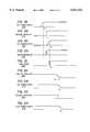
- FIGS. 3A-3Eare a timing diagram illustrating one aspect of the power control process of the present invention.
- FIGS. 4A-4Dare a timing diagram illustrating a second aspect of the power control process of the present invention.
- the flight entertainment system 100includes an interconnect bus 104, a daisy chain 106 of interconnecting seat electronic units (SEUs) 108, 112, 120 and a terminating cap 124.
- SEUsinterconnecting seat electronic units
- Each daisy chain 106is connected such that the output of one SEU is connected to the input of the next SEU until the final seat electronics unit (FSEU) 120 is reached.
- the SEUsreceive the audio and video signals from a Zone Bridge Unit (ZBU) 124.
- Each ZBU 124supports multiple daisy chains 106, 126.
- a Server Network Hub 128coordinates and communicates the information to and from multiple ZBUs 124, 130 to supporting electronics.
- Each SEUe.g. SEU 108, provides the necessary audio and video signals to support a number of passenger seats 132, 136, 140 in the passenger compartment of an aircraft.
- an SEUmay support two to three passenger seats depending on the aircraft configuration used.
- up to 12 SEUsare daisy chained together although the number of SEUs in a daisy chain may vary.
- Each ZBU 124services one section or zone of an aircraft.
- a ZBU 124may service multiple daisy chains 106, 126.
- daisy chain 106, 126may serve an aisle of a plane while each ZBU 124 serves a plane section.
- the bus which forms each daisy chain 106,is terminated at the FSEU 120.
- the FSEUincludes terminating cap 124 which terminates interconnect bus 104.
- ZBU 124distributes audio and video data on a seat network bus 144 and power along AC power line 148 to the various SEUs 108, 112.
- poweris provided by an AC generator 150 located on the aircraft.
- the systemmay also receive data, such as credit card information, entertainment requests, or merchandise orders, from seat electronics (not shown) in the vicinity of passenger seat 132, 136, 140.
- the respective SEU unit 108receives the data and may then transfer the data to the respective ZBU 124 via seat network bus 144. This information may be further transmitted through the server network hub 128 to other electronics aboard the aircraft, or in the case of telephone or other communication to a public switched telephone network ("PSTN”) or other external networks outside of the aircraft through a system interface unit 148.
- a system manager unit (SMU) 152oversees operation of the IFE.
- the SMU 152is coupled to a display device 156 which displays passenger requests and system status information.
- a floppy drive 160is also provided for storing data.
- the IFEincluding the SMU 152 and the SEUs 108, 112, 120 is designed to perform self diagnostic checks.
- the SEUsperform diagnostic checks and may forward error messages to the SMU.
- the SMU 152displays the error on display device 156 or the information is stored on a floppy disk or other removable storage medium 160 for further use or analysis. This information enables technicians or maintenance personnel to quickly troubleshoot the IFE system.
- the server network hub 128may further be coupled to other units which provide information such as Data Server Units (DSUs) 164 and Media Controller Units (MCUs) 168 which provide the video/audio contact.
- DSUsData Server Units
- MCUsMedia Controller Units
- the power control system 200(FIG. 2) of the present invention may be used in controlling the supply of current and voltage to electronic systems which provide in-flight entertainment services such as those shown in FIGS. 1A and 1B.
- electronic systemsinclude, but are not limited to, SEUs 108, 112, 120, System Manager Unit 152, System Interface Unit 148, Data Server Unit 164, and Media Controller Unit 168.
- the power control system 200 of the present inventionmay be implemented in any system that utilizes current or voltage from two different power sources, and is not limited to in-flight entertainment systems.
- FIG. 2is a detailed block diagram of the power control system 200 of the present invention.
- the power control system 200comprises a first power supply 210 and a second power supply 212.
- An example of the first and the second power supplies 210 and 212include a +5 V and a +3.3 V power supply, respectively.
- the first and second power supplies 210 and 212provide regulated current and voltage obtained from a +12 V dc power regulator 190.
- the dc power regular 190in turn obtains supply current and voltage from the AC generator 150 via an AC-to-DC converter 180.
- the first power supply 210provides current and voltage to a voltage detector 214 and a microcontroller 216 via lines 220 and 222 respectively. Upon detection of a valid +5 V signal, the voltage detector 214 issues a control signal via signal line 224 to enable the microcontroller 216.
- An example of the microcontroller 216is that marketed by Intel Corp. under the part designation I196. It is understood by one of ordinary skilled in the art that the microcontroller 216 may be implemented using any microcontroller which obtains current and voltage from a +5 V source.
- the second power supply 212provides supply current and voltage to a processor 226 via line 228.
- the processoris a central processing unit. It is apparent to one of ordinary skill in the art that the second power supply 212 may also be configured to provide current and voltage to a plurality processors.
- the voltage detector 214also issues an enable signal to the second power supply 212 via signal line 230 upon detection of a valid +5 V signal.
- the microcontroller 216issues a signal to the processor 226 via signal line 232 to reset, to boot or to initialize the processor 226. However, this signal is only issued after the processor 226 is powered up by the second power supply 212, to ensure that the processor 226 is in a state to properly receive and to process the signal.
- processor 226is the Pentium processor, the 486 processor as marketed by Intel Corp.
- processor 226include the K6 processor or the 586 processor as marketed by AMD, and the M2 processor as marketed by Cyrix Corp. It is understood by one of ordinary skilled in the art that the processor 226 may be implemented using any processor which obtains current and voltage from a +3.3 V source.
- FIGS. 3A-3Eare timing diagrams illustrating the operational sequence of one aspect of the power control system 200 of the present invention.
- the first power supply 210is enabled to provide current and voltage to the voltage detector 114 and microcontroller 216.
- the voltage detector 214issues an enable signal via line 224 to enable both the microcontroller 216 and the second power supply 212 via signal lines 224 and 230, respectively (see FIGS. 3B and 3D).
- the output of the second power supply 212reaches a valid +3.3 V level (see FIG. 3C).
- the microcontroller 216issues an enable signal to processor 226 to reset, to boot or to initialize the processor 226.
- the processoris reset, booted or initialized (see FIG. 3E). In this manner, the processor 226 will always receive the enable signal after it is powered up by the second power supply 212. As a result, the enable signal will not be considered invalid.
- FIGS. 4A-4Dare timing diagrams illustrating the operational sequence of a second aspect of the power control system 200 of the present invention.
- FIG. 4Aillustrates the voltage output of the 12 V power regulator 190 during a power down sequence.
- the 12 V power regulator 190 sourcegradually tapers off from the +12 V level, beginning at a time t' 0 .
- the first power supply 210Upon reaching a level, at t' 1 , representative of an invalid +12 V signal, the first power supply 210 begins to power down (FIG. 4B).
- the voltage detector 214issues a disable signal to the second power supply 212 and the microcontroller 216.
- the second power supply 212begins to power down.
- the output of the second power supply 212reaches a level representative of an invalid +3.3 V signal, and circuitry powered by the second power supply 212, including the processor 226, are powered down.
- the circuitry driven by the second power supply 212will thus be powered down very shortly after the first power supply 210 has powered down, and preferably before the output of the first power supply 210 has reached the +3.3 V level.
- any potential damage caused by the termination of back biasing provided by the first power (+5 V) supply 210 to circuitry which is also driven by the second (+3.3 V) power supply 212will be eliminated or minimized.
- the period of time between t' 2 and t' 3is 10 ms.
- circuitry utilizing two power suppliesmay be appropriately enabled.
- the implementation of the present inventionensures that circuit integrity will be maintained when the power supplies are turned off.
Landscapes
- Engineering & Computer Science (AREA)
- Power Engineering (AREA)
- Direct Current Feeding And Distribution (AREA)
Abstract
Description
Claims (20)
Priority Applications (3)
| Application Number | Priority Date | Filing Date | Title |
|---|---|---|---|
| US08/901,326US6011322A (en) | 1997-07-28 | 1997-07-28 | Apparatus and method for providing power to circuitry implementing two different power sources |
| PCT/US1998/014090WO1999005764A1 (en) | 1997-07-28 | 1998-07-07 | Apparatus and method for providing power to circuitry implementing two different power sources |
| AU82936/98AAU8293698A (en) | 1997-07-28 | 1998-07-07 | Apparatus and method for providing power to circuitry implementing two differentpower sources |
Applications Claiming Priority (1)
| Application Number | Priority Date | Filing Date | Title |
|---|---|---|---|
| US08/901,326US6011322A (en) | 1997-07-28 | 1997-07-28 | Apparatus and method for providing power to circuitry implementing two different power sources |
Publications (1)
| Publication Number | Publication Date |
|---|---|
| US6011322Atrue US6011322A (en) | 2000-01-04 |
Family
ID=25413951
Family Applications (1)
| Application Number | Title | Priority Date | Filing Date |
|---|---|---|---|
| US08/901,326Expired - LifetimeUS6011322A (en) | 1997-07-28 | 1997-07-28 | Apparatus and method for providing power to circuitry implementing two different power sources |
Country Status (3)
| Country | Link |
|---|---|
| US (1) | US6011322A (en) |
| AU (1) | AU8293698A (en) |
| WO (1) | WO1999005764A1 (en) |
Cited By (37)
| Publication number | Priority date | Publication date | Assignee | Title |
|---|---|---|---|---|
| US20020028700A1 (en)* | 2000-08-24 | 2002-03-07 | Haruhisa Kato | Power control method in wireless communication device |
| US20030070036A1 (en)* | 2001-09-28 | 2003-04-10 | Gorobets Sergey Anatolievich | Memory system for data storage and retrieval |
| US20030079149A1 (en)* | 2001-09-28 | 2003-04-24 | Edwin Payne Robert | Power management system |
| US20030126451A1 (en)* | 2001-09-28 | 2003-07-03 | Gorobets Sergey Anatolievich | Data processing |
| EP1339267A1 (en)* | 2002-02-25 | 2003-08-27 | Audio Partnership Plc | Redundant power supply |
| US20030165076A1 (en)* | 2001-09-28 | 2003-09-04 | Gorobets Sergey Anatolievich | Method of writing data to non-volatile memory |
| US6713992B2 (en)* | 2001-02-15 | 2004-03-30 | Ricoh Company, Ltd. | Method and apparatus for power supply capable of effectively reducing a power consumption |
| US6856045B1 (en) | 2002-01-29 | 2005-02-15 | Hamilton Sundstrand Corporation | Power distribution assembly with redundant architecture |
| US20050044186A1 (en)* | 2003-06-13 | 2005-02-24 | Petrisor Gregory C. | Remote interface optical network |
| US20050055497A1 (en)* | 1995-07-31 | 2005-03-10 | Petro Estakhri | Faster write operations to nonvolatile memory by manipulation of frequently-accessed sectors |
| US20050185067A1 (en)* | 2004-02-23 | 2005-08-25 | Petro Estakhri | Secure compact flash |
| US6950918B1 (en) | 2002-01-18 | 2005-09-27 | Lexar Media, Inc. | File management of one-time-programmable nonvolatile memory devices |
| US6957295B1 (en) | 2002-01-18 | 2005-10-18 | Lexar Media, Inc. | File management of one-time-programmable nonvolatile memory devices |
| US6973519B1 (en) | 2003-06-03 | 2005-12-06 | Lexar Media, Inc. | Card identification compatibility |
| US6978342B1 (en) | 1995-07-31 | 2005-12-20 | Lexar Media, Inc. | Moving sectors within a block of information in a flash memory mass storage architecture |
| US7000064B2 (en) | 2001-09-28 | 2006-02-14 | Lexar Media, Inc. | Data handling system |
| US20060195651A1 (en)* | 1995-07-31 | 2006-08-31 | Petro Estakhri | Increasing the memory performance of flash memory devices by writing sectors simultaneously to multiple flash memory devices |
| US7102671B1 (en) | 2000-02-08 | 2006-09-05 | Lexar Media, Inc. | Enhanced compact flash memory card |
| US7167944B1 (en) | 2000-07-21 | 2007-01-23 | Lexar Media, Inc. | Block management for mass storage |
| US20070077998A1 (en)* | 2005-09-19 | 2007-04-05 | Petrisor Gregory C | Fiber-to-the-seat in-flight entertainment system |
| US7215580B2 (en) | 2001-09-28 | 2007-05-08 | Lexar Media, Inc. | Non-volatile memory control |
| US7231643B1 (en) | 2002-02-22 | 2007-06-12 | Lexar Media, Inc. | Image rescue system including direct communication between an application program and a device driver |
| US7275686B2 (en) | 2003-12-17 | 2007-10-02 | Lexar Media, Inc. | Electronic equipment point-of-sale activation to avoid theft |
| US20080063398A1 (en)* | 2006-09-11 | 2008-03-13 | Cline James D | Fiber-to-the-seat (ftts) fiber distribution system |
| US7370166B1 (en) | 2004-04-30 | 2008-05-06 | Lexar Media, Inc. | Secure portable storage device |
| US20080168281A1 (en)* | 2007-01-05 | 2008-07-10 | Ati Technologies Ulc | Cascaded multi-supply power supply |
| US7464306B1 (en) | 2004-08-27 | 2008-12-09 | Lexar Media, Inc. | Status of overall health of nonvolatile memory |
| US7523249B1 (en) | 1995-07-31 | 2009-04-21 | Lexar Media, Inc. | Direct logical block addressing flash memory mass storage architecture |
| US7594063B1 (en) | 2004-08-27 | 2009-09-22 | Lexar Media, Inc. | Storage capacity status |
| US7725628B1 (en) | 2004-04-20 | 2010-05-25 | Lexar Media, Inc. | Direct secondary device interface by a host |
| US20110065303A1 (en)* | 2009-08-14 | 2011-03-17 | Lumexis Corporation | Video display unit docking assembly for fiber-to-the-screen inflight entertainment system |
| US20110063998A1 (en)* | 2009-08-20 | 2011-03-17 | Lumexis Corp | Serial networking fiber optic inflight entertainment system network configuration |
| US20110162015A1 (en)* | 2009-10-05 | 2011-06-30 | Lumexis Corp | Inflight communication system |
| JP2012191680A (en)* | 2011-03-08 | 2012-10-04 | Ricoh Co Ltd | Power supply device, control method of power supply device, and image formation device |
| US8612779B2 (en)* | 2009-07-22 | 2013-12-17 | Wolfson Microelectronics Plc | Power management apparatus and methods |
| US8659990B2 (en) | 2009-08-06 | 2014-02-25 | Lumexis Corporation | Serial networking fiber-to-the-seat inflight entertainment system |
| GB2526532A (en)* | 2014-05-02 | 2015-12-02 | Harvard Engineering Plc | Power supply apparatus and method |
Citations (3)
| Publication number | Priority date | Publication date | Assignee | Title |
|---|---|---|---|---|
| US4730122A (en)* | 1986-09-18 | 1988-03-08 | International Business Machines Corporation | Power supply adapter systems |
| US5515134A (en)* | 1993-12-10 | 1996-05-07 | Nikon Corporation | Camera power source system |
| US5732914A (en)* | 1996-03-13 | 1998-03-31 | Flinn; John | Gun holder for bedside placement of rifles and shotguns |
Family Cites Families (1)
| Publication number | Priority date | Publication date | Assignee | Title |
|---|---|---|---|---|
| JP3092474B2 (en)* | 1995-04-28 | 2000-09-25 | 日立工機株式会社 | Start prevention device after power failure recovery |
- 1997
- 1997-07-28USUS08/901,326patent/US6011322A/ennot_activeExpired - Lifetime
- 1998
- 1998-07-07AUAU82936/98Apatent/AU8293698A/ennot_activeAbandoned
- 1998-07-07WOPCT/US1998/014090patent/WO1999005764A1/enactiveApplication Filing
Patent Citations (3)
| Publication number | Priority date | Publication date | Assignee | Title |
|---|---|---|---|---|
| US4730122A (en)* | 1986-09-18 | 1988-03-08 | International Business Machines Corporation | Power supply adapter systems |
| US5515134A (en)* | 1993-12-10 | 1996-05-07 | Nikon Corporation | Camera power source system |
| US5732914A (en)* | 1996-03-13 | 1998-03-31 | Flinn; John | Gun holder for bedside placement of rifles and shotguns |
Cited By (103)
| Publication number | Priority date | Publication date | Assignee | Title |
|---|---|---|---|---|
| US20050055497A1 (en)* | 1995-07-31 | 2005-03-10 | Petro Estakhri | Faster write operations to nonvolatile memory by manipulation of frequently-accessed sectors |
| US8078797B2 (en) | 1995-07-31 | 2011-12-13 | Micron Technology, Inc. | Increasing the memory performance of flash memory devices by writing sectors simultaneously to multiple flash memory devices |
| US8793430B2 (en) | 1995-07-31 | 2014-07-29 | Micron Technology, Inc. | Electronic system having memory with a physical block having a sector storing data and indicating a move status of another sector of the physical block |
| US8554985B2 (en) | 1995-07-31 | 2013-10-08 | Micron Technology, Inc. | Memory block identified by group of logical block addresses, storage device with movable sectors, and methods |
| US8397019B2 (en) | 1995-07-31 | 2013-03-12 | Micron Technology, Inc. | Memory for accessing multiple sectors of information substantially concurrently |
| US20070266201A1 (en)* | 1995-07-31 | 2007-11-15 | Petro Estakhri | Increasing the memory performance of flash memory devices by writing sectors simultaneously to multiple flash memory devices |
| US8171203B2 (en) | 1995-07-31 | 2012-05-01 | Micron Technology, Inc. | Faster write operations to nonvolatile memory using FSInfo sector manipulation |
| US7908426B2 (en) | 1995-07-31 | 2011-03-15 | Lexar Media, Inc. | Moving sectors within a block of information in a flash memory mass storage architecture |
| US7263591B2 (en) | 1995-07-31 | 2007-08-28 | Lexar Media, Inc. | Increasing the memory performance of flash memory devices by writing sectors simultaneously to multiple flash memory devices |
| US8032694B2 (en) | 1995-07-31 | 2011-10-04 | Micron Technology, Inc. | Direct logical block addressing flash memory mass storage architecture |
| US9026721B2 (en) | 1995-07-31 | 2015-05-05 | Micron Technology, Inc. | Managing defective areas of memory |
| US20090204750A1 (en)* | 1995-07-31 | 2009-08-13 | Petro Estakhri | Direct logical block addressing flash memory mass storage architecture |
| US7441090B2 (en) | 1995-07-31 | 2008-10-21 | Lexar Media, Inc. | System and method for updating data sectors in a non-volatile memory using logical block addressing |
| US7774576B2 (en) | 1995-07-31 | 2010-08-10 | Lexar Media, Inc. | Direct logical block addressing flash memory mass storage architecture |
| US20090043952A1 (en)* | 1995-07-31 | 2009-02-12 | Lexar Media, Inc. | Moving sectors within a block of information in a flash memory mass storage architecture |
| US6978342B1 (en) | 1995-07-31 | 2005-12-20 | Lexar Media, Inc. | Moving sectors within a block of information in a flash memory mass storage architecture |
| US20060020747A1 (en)* | 1995-07-31 | 2006-01-26 | Petro Estakhri | Moving sectors within a block of information in a flash memory mass storage architecture |
| US7523249B1 (en) | 1995-07-31 | 2009-04-21 | Lexar Media, Inc. | Direct logical block addressing flash memory mass storage architecture |
| US20060195651A1 (en)* | 1995-07-31 | 2006-08-31 | Petro Estakhri | Increasing the memory performance of flash memory devices by writing sectors simultaneously to multiple flash memory devices |
| US7549013B2 (en) | 1995-07-31 | 2009-06-16 | Lexar Media, Inc. | Increasing the memory performance of flash memory devices by writing sectors simultaneously to multiple flash memory devices |
| US7111140B2 (en) | 1995-07-31 | 2006-09-19 | Lexar Media, Inc. | Increasing the memory performance of flash memory devices by writing sectors simultaneously to multiple flash memory devices |
| US7424593B2 (en) | 1995-07-31 | 2008-09-09 | Micron Technology, Inc. | Increasing the memory performance of flash memory devices by writing sectors simultaneously to multiple flash memory devices |
| US7102671B1 (en) | 2000-02-08 | 2006-09-05 | Lexar Media, Inc. | Enhanced compact flash memory card |
| US7167944B1 (en) | 2000-07-21 | 2007-01-23 | Lexar Media, Inc. | Block management for mass storage |
| US7734862B2 (en) | 2000-07-21 | 2010-06-08 | Lexar Media, Inc. | Block management for mass storage |
| US8019932B2 (en) | 2000-07-21 | 2011-09-13 | Micron Technology, Inc. | Block management for mass storage |
| US8250294B2 (en) | 2000-07-21 | 2012-08-21 | Micron Technology, Inc. | Block management for mass storage |
| US20020028700A1 (en)* | 2000-08-24 | 2002-03-07 | Haruhisa Kato | Power control method in wireless communication device |
| USRE41304E1 (en)* | 2001-02-15 | 2010-05-04 | Ricoh Company, Ltd. | Method and apparatus for power supply capable of effectively reducing a power consumption |
| US6713992B2 (en)* | 2001-02-15 | 2004-03-30 | Ricoh Company, Ltd. | Method and apparatus for power supply capable of effectively reducing a power consumption |
| US20100095055A1 (en)* | 2001-09-28 | 2010-04-15 | Lexar Media, Inc. | Memory system for data storage and retrieval |
| US7215580B2 (en) | 2001-09-28 | 2007-05-08 | Lexar Media, Inc. | Non-volatile memory control |
| US9489301B2 (en) | 2001-09-28 | 2016-11-08 | Micron Technology, Inc. | Memory systems |
| US20030165076A1 (en)* | 2001-09-28 | 2003-09-04 | Gorobets Sergey Anatolievich | Method of writing data to non-volatile memory |
| US20080155184A1 (en)* | 2001-09-28 | 2008-06-26 | Lexar Media, Inc. | Methods and apparatus for writing data to non-volatile memory |
| US9032134B2 (en) | 2001-09-28 | 2015-05-12 | Micron Technology, Inc. | Methods of operating a memory system that include outputting a data pattern from a sector allocation table to a host if a logical sector is indicated as being erased |
| US20080215903A1 (en)* | 2001-09-28 | 2008-09-04 | Lexar Media, Inc. | Power management of non-volatile memory systems |
| US20070274150A1 (en)* | 2001-09-28 | 2007-11-29 | Lexar Media, Inc. | Non-volatile memory control |
| US20030070036A1 (en)* | 2001-09-28 | 2003-04-10 | Gorobets Sergey Anatolievich | Memory system for data storage and retrieval |
| US20030079149A1 (en)* | 2001-09-28 | 2003-04-24 | Edwin Payne Robert | Power management system |
| US7254724B2 (en) | 2001-09-28 | 2007-08-07 | Lexar Media, Inc. | Power management system |
| US8694722B2 (en) | 2001-09-28 | 2014-04-08 | Micron Technology, Inc. | Memory systems |
| US8208322B2 (en) | 2001-09-28 | 2012-06-26 | Micron Technology, Inc. | Non-volatile memory control |
| US8135925B2 (en) | 2001-09-28 | 2012-03-13 | Micron Technology, Inc. | Methods of operating a memory system |
| US20030126451A1 (en)* | 2001-09-28 | 2003-07-03 | Gorobets Sergey Anatolievich | Data processing |
| US7944762B2 (en) | 2001-09-28 | 2011-05-17 | Micron Technology, Inc. | Non-volatile memory control |
| US8386695B2 (en) | 2001-09-28 | 2013-02-26 | Micron Technology, Inc. | Methods and apparatus for writing data to non-volatile memory |
| US7340581B2 (en) | 2001-09-28 | 2008-03-04 | Lexar Media, Inc. | Method of writing data to non-volatile memory |
| US7681057B2 (en) | 2001-09-28 | 2010-03-16 | Lexar Media, Inc. | Power management of non-volatile memory systems |
| US7185208B2 (en) | 2001-09-28 | 2007-02-27 | Lexar Media, Inc. | Data processing |
| US7000064B2 (en) | 2001-09-28 | 2006-02-14 | Lexar Media, Inc. | Data handling system |
| US7917709B2 (en) | 2001-09-28 | 2011-03-29 | Lexar Media, Inc. | Memory system for data storage and retrieval |
| US6957295B1 (en) | 2002-01-18 | 2005-10-18 | Lexar Media, Inc. | File management of one-time-programmable nonvolatile memory devices |
| US6950918B1 (en) | 2002-01-18 | 2005-09-27 | Lexar Media, Inc. | File management of one-time-programmable nonvolatile memory devices |
| US6856045B1 (en) | 2002-01-29 | 2005-02-15 | Hamilton Sundstrand Corporation | Power distribution assembly with redundant architecture |
| US7231643B1 (en) | 2002-02-22 | 2007-06-12 | Lexar Media, Inc. | Image rescue system including direct communication between an application program and a device driver |
| US9213606B2 (en) | 2002-02-22 | 2015-12-15 | Micron Technology, Inc. | Image rescue |
| US8166488B2 (en) | 2002-02-22 | 2012-04-24 | Micron Technology, Inc. | Methods of directly accessing a mass storage data device |
| EP1339267A1 (en)* | 2002-02-25 | 2003-08-27 | Audio Partnership Plc | Redundant power supply |
| US20030160513A1 (en)* | 2002-02-25 | 2003-08-28 | Bramble Matthew Forbes | Power supply arrangements |
| US7663265B2 (en) | 2002-02-25 | 2010-02-16 | Audio Partnership Plc | Power supply arrangements |
| US6973519B1 (en) | 2003-06-03 | 2005-12-06 | Lexar Media, Inc. | Card identification compatibility |
| US20050044186A1 (en)* | 2003-06-13 | 2005-02-24 | Petrisor Gregory C. | Remote interface optical network |
| US7275686B2 (en) | 2003-12-17 | 2007-10-02 | Lexar Media, Inc. | Electronic equipment point-of-sale activation to avoid theft |
| US20050185067A1 (en)* | 2004-02-23 | 2005-08-25 | Petro Estakhri | Secure compact flash |
| US7725628B1 (en) | 2004-04-20 | 2010-05-25 | Lexar Media, Inc. | Direct secondary device interface by a host |
| US8090886B2 (en) | 2004-04-20 | 2012-01-03 | Micron Technology, Inc. | Direct secondary device interface by a host |
| US8316165B2 (en) | 2004-04-20 | 2012-11-20 | Micron Technology, Inc. | Direct secondary device interface by a host |
| US10049207B2 (en) | 2004-04-30 | 2018-08-14 | Micron Technology, Inc. | Methods of operating storage systems including encrypting a key salt |
| US20110082979A1 (en)* | 2004-04-30 | 2011-04-07 | Lexar Media, Inc. | Removable storage device |
| US9576154B2 (en) | 2004-04-30 | 2017-02-21 | Micron Technology, Inc. | Methods of operating storage systems including using a key to determine whether a password can be changed |
| US8612671B2 (en) | 2004-04-30 | 2013-12-17 | Micron Technology, Inc. | Removable devices |
| US8151041B2 (en) | 2004-04-30 | 2012-04-03 | Micron Technology, Inc. | Removable storage device |
| US7865659B2 (en) | 2004-04-30 | 2011-01-04 | Micron Technology, Inc. | Removable storage device |
| US7370166B1 (en) | 2004-04-30 | 2008-05-06 | Lexar Media, Inc. | Secure portable storage device |
| US8296545B2 (en) | 2004-08-27 | 2012-10-23 | Micron Technology, Inc. | Storage capacity status |
| US7464306B1 (en) | 2004-08-27 | 2008-12-09 | Lexar Media, Inc. | Status of overall health of nonvolatile memory |
| US7743290B2 (en) | 2004-08-27 | 2010-06-22 | Lexar Media, Inc. | Status of overall health of nonvolatile memory |
| US20090077434A1 (en)* | 2004-08-27 | 2009-03-19 | Lexar Media, Inc. | Status of overall health of nonvolatile memory |
| US20110219175A1 (en)* | 2004-08-27 | 2011-09-08 | Lexar Media, Inc. | Storage capacity status |
| US20100231408A1 (en)* | 2004-08-27 | 2010-09-16 | Lexar Media, Inc. | Display configured to display health status of a memory device |
| US20090327595A1 (en)* | 2004-08-27 | 2009-12-31 | Lexar Media, Inc. | Storage capacity status |
| US7594063B1 (en) | 2004-08-27 | 2009-09-22 | Lexar Media, Inc. | Storage capacity status |
| US7949822B2 (en) | 2004-08-27 | 2011-05-24 | Micron Technology, Inc. | Storage capacity status |
| US20070077998A1 (en)* | 2005-09-19 | 2007-04-05 | Petrisor Gregory C | Fiber-to-the-seat in-flight entertainment system |
| US8184974B2 (en) | 2006-09-11 | 2012-05-22 | Lumexis Corporation | Fiber-to-the-seat (FTTS) fiber distribution system |
| US20080063398A1 (en)* | 2006-09-11 | 2008-03-13 | Cline James D | Fiber-to-the-seat (ftts) fiber distribution system |
| US20080168281A1 (en)* | 2007-01-05 | 2008-07-10 | Ati Technologies Ulc | Cascaded multi-supply power supply |
| US8232677B2 (en)* | 2007-01-05 | 2012-07-31 | Ati Technologies Ulc | Cascaded multi-supply power supply |
| US8612779B2 (en)* | 2009-07-22 | 2013-12-17 | Wolfson Microelectronics Plc | Power management apparatus and methods |
| US8659990B2 (en) | 2009-08-06 | 2014-02-25 | Lumexis Corporation | Serial networking fiber-to-the-seat inflight entertainment system |
| US9532082B2 (en) | 2009-08-06 | 2016-12-27 | Lumexis Corporation | Serial networking fiber-to-the-seat inflight entertainment system |
| US9118547B2 (en) | 2009-08-06 | 2015-08-25 | Lumexis Corporation | Serial networking fiber-to-the-seat inflight entertainment system |
| US20110065303A1 (en)* | 2009-08-14 | 2011-03-17 | Lumexis Corporation | Video display unit docking assembly for fiber-to-the-screen inflight entertainment system |
| US8424045B2 (en) | 2009-08-14 | 2013-04-16 | Lumexis Corporation | Video display unit docking assembly for fiber-to-the-screen inflight entertainment system |
| US8416698B2 (en) | 2009-08-20 | 2013-04-09 | Lumexis Corporation | Serial networking fiber optic inflight entertainment system network configuration |
| US9344351B2 (en) | 2009-08-20 | 2016-05-17 | Lumexis Corporation | Inflight entertainment system network configurations |
| US9036487B2 (en) | 2009-08-20 | 2015-05-19 | Lumexis Corporation | Serial networking fiber optic inflight entertainment system network configuration |
| US20110063998A1 (en)* | 2009-08-20 | 2011-03-17 | Lumexis Corp | Serial networking fiber optic inflight entertainment system network configuration |
| US20110162015A1 (en)* | 2009-10-05 | 2011-06-30 | Lumexis Corp | Inflight communication system |
| JP2012191680A (en)* | 2011-03-08 | 2012-10-04 | Ricoh Co Ltd | Power supply device, control method of power supply device, and image formation device |
| GB2526532A (en)* | 2014-05-02 | 2015-12-02 | Harvard Engineering Plc | Power supply apparatus and method |
| GB2526532B (en)* | 2014-05-02 | 2016-09-28 | Harvard Eng Plc | Power supply apparatus and method |
Also Published As
| Publication number | Publication date |
|---|---|
| AU8293698A (en) | 1999-02-16 |
| WO1999005764A1 (en) | 1999-02-04 |
Similar Documents
| Publication | Publication Date | Title |
|---|---|---|
| US6011322A (en) | Apparatus and method for providing power to circuitry implementing two different power sources | |
| US5942811A (en) | Apparatus and method for extending the supply of reserved power during a line power interruption | |
| US5796185A (en) | Circuit card present sense and protective power supply inhibit for airborne application of ATM switch unit | |
| US6813777B1 (en) | Transaction dispatcher for a passenger entertainment system, method and article of manufacture | |
| US6526159B1 (en) | Eye tracking for resource and power management | |
| US6160591A (en) | Apparatus and method of providing switching frequency synchronization | |
| CA2686770C (en) | System for managing rights of access to avionic applications and data and method implemented by this system | |
| AU6510399A (en) | Aircraft data management system | |
| US7375442B2 (en) | Interface circuit for providing a computer logic circuit with first and second voltages and an associated method | |
| RU94021630A (en) | Aircraft communication and game system, method for control of its operations, data processing system and method for loading information into said system | |
| US20040064743A1 (en) | Remote method for controlling power on an information handling system | |
| WO2003030492A2 (en) | Consolidated in-flight entertainment electronic system | |
| US8653690B2 (en) | Aircraft seat with shared control architecture | |
| US5922056A (en) | Computer system with peripheral device characteristic sensing and automatic communications speed setting | |
| US20190227922A1 (en) | Removable direct attached storage for vehicle entertainment systems | |
| US20190361695A1 (en) | Method for updating firmware of unassigned drives | |
| US5831805A (en) | Local power failure detection and clock disabling circuit | |
| US10636111B2 (en) | Disabling a display refresh process | |
| US20050076249A1 (en) | Modular server system | |
| US6564333B1 (en) | Peripheral device power management circuit and method for selecting between main and auxiliary power sources or from third power source | |
| US6738857B2 (en) | Combined single-ended/differential data bus connector | |
| CN107291486A (en) | The installation method and device of a kind of operating system | |
| US6226699B1 (en) | Method and apparatus for clock selection and switching | |
| US20060164421A1 (en) | Centralized software maintenance of blade computer system | |
| CN109348238A (en) | A kind of voice in live streaming connects wheat method, apparatus, server and storage medium |
Legal Events
| Date | Code | Title | Description |
|---|---|---|---|
| AS | Assignment | Owner name:SONY TRANS COM INC., CALIFORNIA Free format text:ASSIGNMENT OF ASSIGNORS INTEREST;ASSIGNORS:STUMFALL, DAVID M.;SEKINE, KAZUTOYO;REEL/FRAME:008654/0284 Effective date:19970723 Owner name:SONY CORPORATION, JAPAN Free format text:ASSIGNMENT OF ASSIGNORS INTEREST;ASSIGNORS:STUMFALL, DAVID M.;SEKINE, KAZUTOYO;REEL/FRAME:008654/0284 Effective date:19970723 | |
| CC | Certificate of correction | ||
| AS | Assignment | Owner name:ROCKWELL COLLINS, INC., IOWA Free format text:INTELLECTUAL PROPERTY AGREEMENT;ASSIGNOR:SONY CORPORATION;REEL/FRAME:013011/0705 Effective date:20000728 | |
| FPAY | Fee payment | Year of fee payment:4 | |
| SULP | Surcharge for late payment | ||
| REMI | Maintenance fee reminder mailed | ||
| FEPP | Fee payment procedure | Free format text:PETITION RELATED TO MAINTENANCE FEES FILED (ORIGINAL EVENT CODE: PMFP); ENTITY STATUS OF PATENT OWNER: LARGE ENTITY Free format text:PETITION RELATED TO MAINTENANCE FEES GRANTED (ORIGINAL EVENT CODE: PMFG); ENTITY STATUS OF PATENT OWNER: LARGE ENTITY | |
| REIN | Reinstatement after maintenance fee payment confirmed | ||
| FP | Lapsed due to failure to pay maintenance fee | Effective date:20080104 | |
| PRDP | Patent reinstated due to the acceptance of a late maintenance fee | Effective date:20080903 | |
| FPAY | Fee payment | Year of fee payment:8 | |
| STCF | Information on status: patent grant | Free format text:PATENTED CASE | |
| SULP | Surcharge for late payment | ||
| AS | Assignment | Owner name:ROCKWELL COLLINS, INC., IOWA Free format text:CORRECTIVE ASSIGNMENT TO CORRECT THE NAME OF CONVEYING PARTY ON COVER PAGE WAS TYPED INCORRECTLY PREVIOUSLY RECORDED ON REEL 013011 FRAME 0705;ASSIGNOR:SONY TRANS COM;REEL/FRAME:022277/0807 Effective date:20000728 | |
| FPAY | Fee payment | Year of fee payment:12 | |
| SULP | Surcharge for late payment | Year of fee payment:11 |