US6010623A - Bubble trap with flat side - Google Patents
Bubble trap with flat sideDownload PDFInfo
- Publication number
- US6010623A US6010623AUS09/073,303US7330398AUS6010623AUS 6010623 AUS6010623 AUS 6010623AUS 7330398 AUS7330398 AUS 7330398AUS 6010623 AUS6010623 AUS 6010623A
- Authority
- US
- United States
- Prior art keywords
- chamber
- flow
- port
- bubble trap
- horizontal
- Prior art date
- Legal status (The legal status is an assumption and is not a legal conclusion. Google has not performed a legal analysis and makes no representation as to the accuracy of the status listed.)
- Expired - Lifetime
Links
Images


Classifications
- A—HUMAN NECESSITIES
- A61—MEDICAL OR VETERINARY SCIENCE; HYGIENE
- A61M—DEVICES FOR INTRODUCING MEDIA INTO, OR ONTO, THE BODY; DEVICES FOR TRANSDUCING BODY MEDIA OR FOR TAKING MEDIA FROM THE BODY; DEVICES FOR PRODUCING OR ENDING SLEEP OR STUPOR
- A61M1/00—Suction or pumping devices for medical purposes; Devices for carrying-off, for treatment of, or for carrying-over, body-liquids; Drainage systems
- A61M1/36—Other treatment of blood in a by-pass of the natural circulatory system, e.g. temperature adaptation, irradiation ; Extra-corporeal blood circuits
- A61M1/3621—Extra-corporeal blood circuits
- A61M1/3627—Degassing devices; Buffer reservoirs; Drip chambers; Blood filters
- B—PERFORMING OPERATIONS; TRANSPORTING
- B01—PHYSICAL OR CHEMICAL PROCESSES OR APPARATUS IN GENERAL
- B01D—SEPARATION
- B01D19/00—Degasification of liquids
- B01D19/0031—Degasification of liquids by filtration
- A—HUMAN NECESSITIES
- A61—MEDICAL OR VETERINARY SCIENCE; HYGIENE
- A61M—DEVICES FOR INTRODUCING MEDIA INTO, OR ONTO, THE BODY; DEVICES FOR TRANSDUCING BODY MEDIA OR FOR TAKING MEDIA FROM THE BODY; DEVICES FOR PRODUCING OR ENDING SLEEP OR STUPOR
- A61M2205/00—General characteristics of the apparatus
- A61M2205/12—General characteristics of the apparatus with interchangeable cassettes forming partially or totally the fluid circuit
- Y—GENERAL TAGGING OF NEW TECHNOLOGICAL DEVELOPMENTS; GENERAL TAGGING OF CROSS-SECTIONAL TECHNOLOGIES SPANNING OVER SEVERAL SECTIONS OF THE IPC; TECHNICAL SUBJECTS COVERED BY FORMER USPC CROSS-REFERENCE ART COLLECTIONS [XRACs] AND DIGESTS
- Y10—TECHNICAL SUBJECTS COVERED BY FORMER USPC
- Y10T—TECHNICAL SUBJECTS COVERED BY FORMER US CLASSIFICATION
- Y10T137/00—Fluid handling
- Y10T137/8593—Systems
- Y10T137/86292—System with plural openings, one a gas vent or access opening
Definitions
- Chambers for blood setsare commonly used in most or all blood sets for the prime purpose of removing gas bubbles from the blood. Such gas bubbles can interfere with the operation of dialyzers, and can be injurious to a patient if allowed to return to the arteriovenous system of the patient.
- Conventional bubble trapscomprise a typically rigid or semi-rigid tube in which a blood inlet is provided to convey blood into the top of the chamber, while a blood outlet draws blood from the bottom of the chamber. Bubbles are thus given the opportunity to rise to the top of the chamber so that the blood in the bottom of the chamber, which is withdrawn to pass through another portion of the blood set, is relatively free of bubbles, since they migrate to the top of the chamber.
- such bubble trapsare taller than they are wide, to provide a deep, vertical chamber for the blood so that bubbles are kept away from the bottom of the chamber from which the blood is being withdrawn.
- the inlets of the prior art bubble chambersare variably positioned, the idea being that the blood entering into such inlets, and the bubbles contained in the blood, will initially stay in an upper portion of the chamber so that the bubbles have time to migrate upwardly through a liquid level to a gas space at the top of the chamber.
- Some inletsare vertically oriented, extending downwardly from the top of the chamber. Because of the height of the chamber, inflowing blood stops moving downwardly before the bubbles contained in it can be caught in the outlet flow.
- Other inlets of the prior artare vertically oriented in the bottom of the chamber, to propel the inlet blood upwardly toward the chamber top.
- inletsare horizontally oriented in the side of the chamber, so that the inlet flow must horizontally cross the downward flow of the bulk blood in the chamber, moving to an opposite sidewall where it is turned upwardly. This raises the possibility of bubbles being entrained in the downward flow before they are turned upwardly to reach the intended air space.
- the bubble trapping principles of the prior artare effective with large, buoyant bubbles, typically having a volume greater than 50 microliters, and at relatively low flow rates of less than 300 ml. per minute.
- Blood chambers for trapping bubblestypically have volumes of about 15-25 ml.
- the buoyancy of the bubblestypically urges them to the surface at a velocity greater than the downward velocity of the bulk flow of the fluid in the bubble trap.
- wide bubble trapsare disclosed in which the width of the bubble trapping chamber is preferably wider than the height of the chamber.
- the fluid inlet and fluid outlet to these chambersare then laterally spaced from each other to provide a fluid flow pattern which is substantially horizontal in nature, with less of a vertical flow component than in the prior art. This has been found to facilitate the migration of bubbles upwardly to the top of the chamber.
- a bubble trap chamberspecifically shown to be cylindrical, contains a central inlet/outlet tube which serves as the inlet from one end and the outlet from the other end, having side apertures and a partition between the apertures to block direct flow between the inlet portion and the outlet portion of the tube.
- a flow-through bubble trap for fluid flow linesis disclosed.
- a bubble trapis typically provided as a component of arteriovenous blood sets for dialysis or any other blood processing procedure, where blood flows through the bubble trap by first entering and then exiting it, leaving gas bubbles behind.
- the bubble trapcan be used as a convenient site for the access of auxiliary branch lines, which may connect to pressure monitors, sources of IV solution, sources of heparin or the like.
- the bubble trapdefines a chamber having top, bottom and side walls.
- the chamberdefines a substantially flat, lateral side, which can be placed next to any of a variety of dialysis machines with a good operating fit.
- dialysis machinesare many of the models sold by Fresenius, Althin, and Baxter International.
- a first port tubecommunicates upwardly into the chamber, typically through the bottom wall.
- a second port tubecommunicates downwardly into the chamber, typically through the top wall.
- a flow-directing systemmay preferably be positioned adjacent to the bottom wall, to direct incoming fluid from one of the port tubes, typically the bottom port tube for "prepump” chamber location or the top port tube for "postpump” chamber location, into a first, lateral flow direction relative to the direction of flow within the port tubes. From there, the flowing fluid enters into a substantially horizontal fluid flow circulation in the chamber, exhibiting only a relatively minor vertical flow component, contrary to many chambers of the prior art.
- the flow directing systemalso allows fluid flow from the circulating fluid in the chamber to flow into the other of the port tubes in a lateral flow direction that is generally the same direction as the first lateral flow direction, while preventing direct flow between the first and second port tubes.
- the chamber of this inventionhas substantially rectangular sidewalls, plus a horizontal width that is at least as great as the height of the chamber and preferably greater than the chamber height. This causes the circulating flow within the chamber to be mostly horizontal in nature.
- the horizontal thickness or depth of the chamber of this inventionis preferably less than both the horizontal width thereof and the height of the chamber.
- the chambermay have a width on the order of 4 or 5 cm. and an internal volume which is preferably no more than about 25 cc.
- At least one and typically both of the port tubesare positioned closely adjacent to the flat, lateral side described above, which facilitates fitting of the chamber on a wide variety of dialysis machines. That port tube positioned adjacent to the flat, lateral side may directly connect to a length of roller pump tubing without the need for an intermediate length of flow tubing. This provides an added economy by eliminating such an intermediate length of tubing.
- the sidewallspreferably carry at least one inwardly extending, generally horizontal vane to slow the vertical flow component of the substantially horizontal flow circulation. This can further reduce the number of microbubbles of gas which escape through the bubble trap into the outlet flow of blood.
- the flow directing system of this inventionmay comprise an angled wall as a baffle, which is positioned between the first and second port tubes to prevent their direct flow connection with each other.
- the baffle systemmay further comprise horizontal wall portions to direct incoming fluid laterally.
- bloodenters the bubble trap chamber and is directed to one lateral side, preferably along its longest lateral dimension. From there, the blood circulates through essentially the entire lateral width of the major side of the bubble trap, being collected into a passageway from a position adjacent to the opposed lateral side of the chamber. This maximizes the time of horizontal blood flow, which, in turn, gives maximum time for microbubbles to rise to the top of the chamber, where they may be trapped.
- the chamber of this inventionmay also carry other ports for connection with branch tubing which may connect to a pressure monitor device, a source of saline solution and/or heparin, and the like.
- a pressure monitor portmay be provided on the respective chamber to communicate with the "highest" portion of the enclosed volume within the chamber irrespectively of whether the chamber is oriented with its back wall in a vertical position, a downwardly facing position, or rotated laterally by approximately 90° while remaining vertical.
- an array of access portscarried on blood sets, comprising injection sites and/or branch lines communicating with the set for the administration of medicaments or obtaining blood samples.
- Prior art injection sites and branch linesappear on main tubes, chamber top caps, chamber walls, or on the IV priming set.
- a typical arterial or venous blood tubing setwill have three or more access ports. This is due to the variety of modalities of administration and sampling, being influenced by the following factors;
- access portssuch as injection sites on the main tubes are suitable for simple drug delivery or blood sampling as the injection sites directly access the blood stream.
- injection sitesare not suitable for diluting drugs or following drug administration with a saline flush.
- the prior artplaces an injection site on the IV administration tube away from the blood flow tubing. Of course, this makes such injection sites unsuitable for blood sampling.
- injection sites on the chamber top capsare suitable for fluid administration, but not for sampling, as the site is adjacent an air space above the blood.
- prior art blood tubing setsare equipped with many different kinds of access ports to handle the variety of modalities.
- a flow-through bubble traphaving a main chamber and first and sealed port tubes communicating with the main chamber for main fluid flow therethrough.
- a central manifoldis provided which communicates with one of the port tubes adjacent to the chamber.
- a plurality of auxiliary portscommunicate with the central manifold.
- the auxiliary portscomprise an injection port positioned on the manifold so that an injection needle can penetrate through the injection port and extend into the main fluid flow of the one port tube.
- Another of the auxiliary portstypically communicates with the length of flexible tubing for connection with a source of intravenous solution.
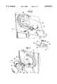
- FIG. 1is a fragmentary, perspective view showing an arterial blood set for hemodialysis carried on a roller pump of a conventional dialysis machine;
- FIG. 2is an enlarged, elevational view of the chamber of this invention with portions broken away;
- FIG. 3is a sectional view taken along line 3--3 of FIG. 2;
- FIG. 4is a sectional view taken along line 4--4 of FIG. 2;
- FIG. 5is a perspective view of the arterial blood set of FIG. 1, inserted into a different roller pump which is substantially horizontally positioned;
- FIG. 6is an elevational view of the arrangement of FIG. 5.
- FIG. 7is a perspective view of the blood set of FIG. 1 installed in another roller pump set which is rotated about 90° from the roller pump of FIG. 1, so that the roller pump tubing is inserted laterally into the roller pump.
- a conventional dialysis machine 10having a face plate 12 through which a roller pump 14 projects.
- An arterial set for hemodialysis 16is provided, being of generally conventional construction except as otherwise indicated herein.
- Arterial set 16carries conventional roller pump tubing 18 fitted into the roller pump 14 in a conventional manner.
- Roller pump tubing 18connects with a flow-through bubble trap chamber 20 in accordance with this invention.
- Bubble trap chamber 20has several ports that respectively connect with the main flow tubing 22 of arterial set 16 and branch connection lines 24, 26, which may be conventional in design per se, and are provided for the purpose of connection with a pressure monitor, a source of IV solution, a source of heparin, or the like.
- Chamber 20can also carry an aperture 28 which is filled with an elastomer-type resealable injection site.
- Branch connection line 26 and the corresponding portcommunicates with chamber 20 and serves as the pressure monitor port and line.
- the line and port 26communicate with the "highest" portion of the volume enclosed in chamber 20 when back wall 36 is in the vertical position as shown, but also if back wall 36 is in a substantially horizontal position as in FIGS. 5 and 6, or if chamber 20 is rotated so that sidewall 38 is the lowest wall in the position of use of chamber 20, as in FIG. 7.
- roller tubing 18rotates clockwise in direction, chamber 20 is in a "pre-pump" location, and blood flows from main flow tubing 22 to roller tubing 18. Pressures in the chamber are then typically negative, and port 24 is typically a source for IV solution administration. If roller tube 18 rotates counterclockwise, chamber 20 is in a post-pump location. Flows proceed from roller tubing 18 to main flow tubing 22. Pressures then are typically positive in chamber 20.
- FIG. 2shows chamber 12 to be substantially, but not exactly, rectangular in shape, having a top wall 30, a bottom wall 32, opposed major sidewalls 34, 36 and opposed minor sidewalls 38, 40. It can be seen that chamber 20 is wider than it is tall, so that the flow circulation through the chamber is substantially horizontal, with only a relatively minor vertical flow component.
- Chamber 20defines a first port 42 that communicates upwardly into the chamber. Chamber 20 also defines a second port 44 that communicates downwardly into the chamber, passing through upper wall 30, as first port 42 extends through lower wall 32.
- a flow-directing baffle system 46is provided adjacent to bottom wall 32, to direct incoming fluid from one of the port tubes 42, 44 into a first lateral flow direction.
- the baffle system 46comprises an angled wall 48 positioned between the top of first port tube 42 and the bottom of second port tube 44.
- Baffle system 46also comprises horizontal wall portions 50, through which second port 44 passes, and which portions 50 connect with angled wall 48.
- the sides or ends 52, 53 under horizontal wall 50are open to the interior of chamber 20, while walls 48, 50 extend to join (as a part of or abutting against) major sidewalls 34, 36.
- Sidewall 36may comprise the flat back wall previously discussed, which permits installation of the chamber of this invention into a large variety of hemodialysis machines.
- Flow-through chamber 20can pass flow in either direction with substantially similar results. If the flow is upward, with first port tube 42 connected to and receiving blood from set tube 22, the blood rises upwardly into the first space 54, defined by the lower surface of angled wall 48 and a portion of horizontal wall 50, to flow to the left through open side or end 52 in a horizontal manner, and thus to enter into circulating flow within chamber 20.
- the upward motion of such blood in circulating flowis restricted but not eliminated by the presence of horizontal vane 56, which is carried by minor sidewall 40.
- Bloodis then withdrawn from chamber 20 through a passageway 58 defined by the upper surface of angled wall 48 and a right hand portion of horizontal wall 50, blood being drawn in from the open side or end 53 from the circulating flow of blood within the chamber, to be drawn upwardly through second port tube 44, and from there into roller pump tubing 18, which is conventionally attached to second port tubing 44.
- Second horizontal vane 56ais provided to further restrict but not eliminate the vertical flow component in the chamber.
- roller pump tubing 18 and second port tube 44are positioned along rear sidewall 36 of the chamber. This facilitates the fitting of sets carrying the chamber of this invention with a larger number of commercially available hemodialysis machines, so that the number of different designs and codes of respective arterial (and venous) sets using the chamber of this invention may be reduced.
- FIG. 5in which the chamber works with a conventional blood pump 14a that is essentially horizontal rather than vertical.
- the back wall 36 of FIGS. 3-4becomes bottom wall 36 of FIG. 5.
- the flows in chamber 20 of FIGS. 5-6are still primarily horizontal rather than vertical, so that the chamber functions as described above for the original orientation.
- this chambermay be used on dialysis machines in which the roller pump is substantially horizontal.
- FIG. 7Some other machines have blood pumps with a vertical orientation, but with the pump's opening turned to the side.
- pump 14bshows this orientation.
- Chamber 20here is positioned on its side such that the sidewall 38 of FIG. 2 becomes the bottom wall 38 of FIG. 7.
- Monitor tubing and port 26 of FIG. 2remains the monitor tubing in the same port of the FIG. 5 and FIG. 7 embodiments.
- the monitor tubing in port 26still communicates with the highest point in the chamber, and thus is unlikely to pick up blood from the chamber. However, air can be vented through this port and tubing 26 as desired.
- the chamber of this inventiondefines a central manifold passage 60, which serves as a plenum for the mutual connection of injection site port 28, branch or auxiliary tubing 24 (and the port to which it is attached), and first port tube 42, so that they all can connect with space 54.
- Space 54in turn connects with the main portion of the chamber interior.
- Tubing 24may preferably comprise a full priming set of conventional design.
- central manifold 60 and its connecting arrangement with injection site 28, line and port 24 (typically used for priming), and first port tube 42 which connects with line 22are arranged to permit all of the desired arterial administrations and samplings as described below.
- manifold 60is substantially cylindrical with injection site 28 positioned at one end and positioned perpendicular to the main flow of fluid through port tube 22 and its connecting port 42.
- a regular medicamentmay be infused by cannula through injection site 28 directly into the blood stream, with the cannula entering central manifold 60 into main port 42 so as to be in the direct stream of flow.
- a cannulamay be a sharp cannula or a blunt cannula in the manner of the blunt cannula described in Utterberg Patent No. 5,071,413.
- Injection site 28may carry a solid or a slit elastomer partition 28a, or it may comprise a branch line with a female luer connector, or a stop cock, or any such suitable flow control connection.
- a toxic medicamentmay be infused by a cannula through injection site 28, while simultaneously infusing saline via tubing and port 24.
- the central manifold 60allows a dilution space for mixing of the drug with the saline and then the blood.
- An expensive or low volume drugmay be infused by cannula through injection site 28, followed by a saline flush via saline port 24, which clears any residue drug from central manifold 60 and passes it into the main flow of port 42.
- Bloodmay be sampled by passing a cannula through injection site 28 and central manifold 60 to extend directly into the main flow path for blood in port 42.
- medicamentmay be administered through solution line 24.
- the number of access ports required on a blood conveying setcan be reduced to two ports, which can serve every needed function of medicament administration and sampling that can be achieved from the particular location.
- Branch line at 26may then connect to a pressure sensing monitor.
- chamber 20can be molded in a cup-shaped configuration as shown in FIG. 4. Then, separately molded front wall 34 may be attached and sealed at the molded sealing groove 62, which engages with each of the walls to provide a hermetically sealed chamber except at its various access ports.
Landscapes
- Health & Medical Sciences (AREA)
- Vascular Medicine (AREA)
- Heart & Thoracic Surgery (AREA)
- Biomedical Technology (AREA)
- Cardiology (AREA)
- Chemical Kinetics & Catalysis (AREA)
- Engineering & Computer Science (AREA)
- Anesthesiology (AREA)
- Chemical & Material Sciences (AREA)
- Hematology (AREA)
- Life Sciences & Earth Sciences (AREA)
- Animal Behavior & Ethology (AREA)
- General Health & Medical Sciences (AREA)
- Public Health (AREA)
- Veterinary Medicine (AREA)
- External Artificial Organs (AREA)
Abstract
Description
Claims (23)
Priority Applications (1)
| Application Number | Priority Date | Filing Date | Title |
|---|---|---|---|
| US09/073,303US6010623A (en) | 1997-08-01 | 1998-05-05 | Bubble trap with flat side |
Applications Claiming Priority (2)
| Application Number | Priority Date | Filing Date | Title |
|---|---|---|---|
| US90524597A | 1997-08-01 | 1997-08-01 | |
| US09/073,303US6010623A (en) | 1997-08-01 | 1998-05-05 | Bubble trap with flat side |
Related Parent Applications (1)
| Application Number | Title | Priority Date | Filing Date |
|---|---|---|---|
| US90524597ADivision | 1996-11-26 | 1997-08-01 |
Publications (1)
| Publication Number | Publication Date |
|---|---|
| US6010623Atrue US6010623A (en) | 2000-01-04 |
Family
ID=25420487
Family Applications (2)
| Application Number | Title | Priority Date | Filing Date |
|---|---|---|---|
| US09/073,303Expired - LifetimeUS6010623A (en) | 1997-08-01 | 1998-05-05 | Bubble trap with flat side |
| US09/203,013Expired - LifetimeUS5980741A (en) | 1997-08-01 | 1998-12-01 | Bubble trap with flat side having multipurpose supplemental ports |
Family Applications After (1)
| Application Number | Title | Priority Date | Filing Date |
|---|---|---|---|
| US09/203,013Expired - LifetimeUS5980741A (en) | 1997-08-01 | 1998-12-01 | Bubble trap with flat side having multipurpose supplemental ports |
Country Status (1)
| Country | Link |
|---|---|
| US (2) | US6010623A (en) |
Cited By (33)
| Publication number | Priority date | Publication date | Assignee | Title |
|---|---|---|---|---|
| US6171484B1 (en)* | 1997-03-03 | 2001-01-09 | Dsu Medical Corporation | Bubble trap having inlet/outlet tube and docking port |
| US6206954B1 (en)* | 1998-05-13 | 2001-03-27 | Dsu Medical Corporation | Blood set and chamber |
| RU2219959C2 (en)* | 2000-10-09 | 2003-12-27 | Федеральное государственное унитарное предприятие Научно-исследовательский институт электромеханики | Infusion device for injection of fluids within a wide range of transparency |
| US20050054968A1 (en)* | 2003-09-05 | 2005-03-10 | Gambro Dasco S.P.A. | Blood chamber for extracorporeal blood circuits and a process for manufacturing the blood chamber |
| US20050247203A1 (en)* | 2002-06-24 | 2005-11-10 | Jacques Chevallet | Gas separation devices |
| US20090088675A1 (en)* | 2007-10-01 | 2009-04-02 | Baxter International Inc. | Fluid and air handling in blood and dialysis circuits |
| US20090084719A1 (en)* | 2007-10-01 | 2009-04-02 | Baxter International Inc. | Dialysis systems having air separation chambers with internal structures to enhance air removal |
| US20090084718A1 (en)* | 2007-10-01 | 2009-04-02 | Baxter International Inc. | Dialysis systems having air traps with internal structures to enhance air removal |
| US20090084721A1 (en)* | 2007-10-01 | 2009-04-02 | Baxter International Inc. | Dialysis systems having air separation chambers with internal structures to enhance air removal |
| US20090101576A1 (en)* | 2007-10-22 | 2009-04-23 | Baxter International Inc. | Priming and air removal systems and methods for dialysis |
| US8114276B2 (en) | 2007-10-24 | 2012-02-14 | Baxter International Inc. | Personal hemodialysis system |
| US8382711B2 (en) | 2010-12-29 | 2013-02-26 | Baxter International Inc. | Intravenous pumping air management systems and methods |
| US9101709B2 (en) | 2002-06-04 | 2015-08-11 | Fresenius Medical Care Deutschland Gmbh | Dialysis fluid cassettes and related systems and methods |
| US9328969B2 (en) | 2011-10-07 | 2016-05-03 | Outset Medical, Inc. | Heat exchange fluid purification for dialysis system |
| US9402945B2 (en) | 2014-04-29 | 2016-08-02 | Outset Medical, Inc. | Dialysis system and methods |
| US9486590B2 (en) | 2014-09-29 | 2016-11-08 | Fenwal, Inc. | Automatic purging of air from a fluid processing system |
| US9545469B2 (en) | 2009-12-05 | 2017-01-17 | Outset Medical, Inc. | Dialysis system with ultrafiltration control |
| US10179200B2 (en) | 2002-07-19 | 2019-01-15 | Baxter International Inc. | Disposable cassette and system for dialysis |
| WO2019099157A1 (en) | 2017-11-14 | 2019-05-23 | Fresenius Medical Care Holdings, Inc. | Removal of microbubbles through drip chamber nucleation sites |
| US10625009B2 (en) | 2016-02-17 | 2020-04-21 | Baxter International Inc. | Airtrap, system and method for removing microbubbles from a fluid stream |
| US10646634B2 (en) | 2008-07-09 | 2020-05-12 | Baxter International Inc. | Dialysis system and disposable set |
| US11495334B2 (en) | 2015-06-25 | 2022-11-08 | Gambro Lundia Ab | Medical device system and method having a distributed database |
| US11516183B2 (en) | 2016-12-21 | 2022-11-29 | Gambro Lundia Ab | Medical device system including information technology infrastructure having secure cluster domain supporting external domain |
| US11534537B2 (en) | 2016-08-19 | 2022-12-27 | Outset Medical, Inc. | Peritoneal dialysis system and methods |
| US11712501B2 (en) | 2019-11-12 | 2023-08-01 | Fresenius Medical Care Deutschland Gmbh | Blood treatment systems |
| US11724013B2 (en) | 2010-06-07 | 2023-08-15 | Outset Medical, Inc. | Fluid purification system |
| US11730871B2 (en) | 2019-11-12 | 2023-08-22 | Fresenius Medical Care Deutschland Gmbh | Blood treatment systems |
| US11752247B2 (en) | 2019-11-12 | 2023-09-12 | Fresenius Medical Care Deutschland Gmbh | Blood treatment systems |
| US11925736B2 (en) | 2019-11-12 | 2024-03-12 | Fresenius Medical Care Deutschland Gmbh | Blood treatment systems |
| US12201762B2 (en) | 2018-08-23 | 2025-01-21 | Outset Medical, Inc. | Dialysis system and methods |
| US12285553B2 (en) | 2019-11-12 | 2025-04-29 | Fresenius Medical Care Deutschland Gmbh | Blood treatment systems |
| US12329890B2 (en) | 2019-11-12 | 2025-06-17 | Fresenius Medical Care Deutschland Gmbh | Blood treatment systems |
| US12390565B2 (en) | 2019-04-30 | 2025-08-19 | Outset Medical, Inc. | Dialysis systems and methods |
Families Citing this family (12)
| Publication number | Priority date | Publication date | Assignee | Title |
|---|---|---|---|---|
| US6051134A (en)* | 1997-03-28 | 2000-04-18 | Medisystems Technology Corporation | Bubble trap having common inlet/outlet tube |
| US8100866B2 (en)* | 2005-03-24 | 2012-01-24 | B. Braun Medical Inc. | Needleless access port valves |
| IL175460A (en) | 2006-05-07 | 2011-05-31 | Doron Aurbach | Drug delivery device |
| US9687186B2 (en) | 2005-07-21 | 2017-06-27 | Steadymed Ltd. | Drug delivery device |
| US8092414B2 (en)* | 2005-11-09 | 2012-01-10 | Nxstage Medical, Inc. | Diaphragm pressure pod for medical fluids |
| US7935086B2 (en)* | 2006-12-14 | 2011-05-03 | L M M Global Innovations, Inc. | Multiple drug injection apparatus |
| US8196846B2 (en)* | 2008-12-02 | 2012-06-12 | S.C. Johnson & Son, Inc. | Manifold for automated sprayer |
| KR20140039132A (en) | 2010-09-27 | 2014-04-01 | 스테디메드 리미티드 | Size-efficient drug-delivery device |
| US9551625B2 (en) | 2011-05-31 | 2017-01-24 | Nxstage Medical, Inc. | Pressure measurement devices, methods, and systems |
| WO2013136327A1 (en) | 2012-03-15 | 2013-09-19 | Steadymed Ltd. | Enhanced infusion-site pain-reduction for drug-delivery devices |
| ES2715311T3 (en) | 2012-03-19 | 2019-06-03 | Steadymed Ltd | Fluid connection mechanism for patch type pumps |
| US10463847B2 (en) | 2015-06-11 | 2019-11-05 | Steadymed Ltd. | Infusion set |
Citations (46)
| Publication number | Priority date | Publication date | Assignee | Title |
|---|---|---|---|---|
| US3287885A (en)* | 1964-08-05 | 1966-11-29 | Odederlin & Cie Ag | Air separator for drain pipes |
| US3342019A (en)* | 1964-08-12 | 1967-09-19 | Technicon Corp | Gas and liquid separator for gas analysis |
| US3527572A (en)* | 1965-10-11 | 1970-09-08 | A Edward Urkiewicz | Apparatus for treating blood |
| US3795088A (en)* | 1972-03-03 | 1974-03-05 | W Esmond | Degassing particulate matter and oil filter device |
| US3908653A (en)* | 1974-01-23 | 1975-09-30 | Vital Assists | Blood chamber |
| GB1408319A (en)* | 1971-12-23 | 1975-10-01 | Baxter Laboratories Inc | Bubble trap |
| US3996027A (en)* | 1974-10-31 | 1976-12-07 | Baxter Laboratories, Inc. | Swirling flow bubble trap |
| US4031891A (en)* | 1975-11-03 | 1977-06-28 | Baxter Travenol Laboratories, Inc. | Air eliminating filter |
| US4048995A (en)* | 1975-08-15 | 1977-09-20 | Baxter Travenol Laboratories, Inc. | Injection site |
| US4102655A (en)* | 1977-05-02 | 1978-07-25 | Cobe Laboratories, Inc. | Bubble trap |
| US4137160A (en)* | 1974-10-31 | 1979-01-30 | Baxter Travenol Laboratories, Inc. | Device for separating low density material such as gas bubbles from a liquid, and the use thereof in a dialysis delivery system |
| GB1554810A (en)* | 1977-10-03 | 1979-10-31 | Star Oy Ab | Method of preparing furocoumarins |
| US4293413A (en)* | 1979-12-28 | 1981-10-06 | Baxter Travenol Laboratories, Inc. | Dialyzer blood circuit and bubble traps |
| US4311137A (en)* | 1980-04-30 | 1982-01-19 | Sherwood Medical Industries Inc. | Infusion device |
| US4345999A (en)* | 1978-04-27 | 1982-08-24 | Dr. Eduard Fresenius, Chemisch-Pharmazeutische Industrie K.G., Apparatebau K.G. | Apparatus for preventing the entry of air into an artificial organ |
| US4493705A (en)* | 1982-08-10 | 1985-01-15 | Bentley Laboratories, Inc. | Blood reservoir |
| EP0058325B1 (en)* | 1981-02-16 | 1985-03-27 | Gambro Dialysatoren K.G. | Flow-through chamber forming part of a blood duct |
| US4531937A (en)* | 1983-01-24 | 1985-07-30 | Pacesetter Systems, Inc. | Introducer catheter apparatus and method of use |
| US4568333A (en)* | 1983-04-12 | 1986-02-04 | Sawyer Philip Nicholas | Valve arrangement especially suitable for preventing introduction of air into vascular systems |
| US4622032A (en)* | 1984-10-27 | 1986-11-11 | Terumo Kabushiki Kaisha | Blood reservoir |
| US4643713A (en)* | 1984-11-05 | 1987-02-17 | Baxter Travenol Laboratories, Inc. | Venous reservoir |
| US4666598A (en)* | 1985-06-25 | 1987-05-19 | Cobe Laboratories, Inc. | Apparatus for use with fluid flow transfer device |
| US4681606A (en)* | 1986-02-26 | 1987-07-21 | Cobe Laboratories, Inc. | Drip chamber |
| US4722725A (en)* | 1983-04-12 | 1988-02-02 | Interface Biomedical Laboratories, Inc. | Methods for preventing the introduction of air or fluid into the body of a patient |
| US4722731A (en)* | 1985-04-08 | 1988-02-02 | Vailancourt Vincent L | Air check valve |
| US4734269A (en)* | 1985-06-11 | 1988-03-29 | American Hospital Supply Corporation | Venous reservoir bag with integral high-efficiency bubble removal system |
| EP0318993A2 (en)* | 1987-12-04 | 1989-06-07 | Terumo Kabushiki Kaisha | Blood filter |
| EP0350675A2 (en)* | 1988-06-21 | 1990-01-17 | Terumo Kabushiki Kaisha | Blood reservoir |
| US5061236A (en)* | 1990-07-16 | 1991-10-29 | Baxter International Inc. | Venous reservoir with improved inlet configuration and integral screen for bubble removal |
| US5061365A (en)* | 1991-01-22 | 1991-10-29 | Utterberg David S | Medical fluid flow set |
| US5112480A (en)* | 1987-07-07 | 1992-05-12 | Terumo Kabushiki Kaisha | Blood reservoir |
| US5204000A (en)* | 1992-01-31 | 1993-04-20 | Zcl Mfg Canada Inc. | Tank for separating water and hydrocarbon fuels from contaminated water |
| US5228889A (en)* | 1991-03-01 | 1993-07-20 | Hospal Industrie | Device for eliminating bubbles of gas in a flowing liquid |
| EP0587251A1 (en)* | 1989-05-31 | 1994-03-16 | Baxter International Inc. | Blood/gas separator and flow system |
| US5328461A (en)* | 1992-04-30 | 1994-07-12 | Utterberg David S | Blow molded venous drip chamber for hemodialysis |
| US5356376A (en)* | 1990-03-08 | 1994-10-18 | Zoran Milijasevic | Flow controllers for fluid infusion sets |
| US5358481A (en)* | 1993-06-03 | 1994-10-25 | Research Medical, Inc. | Apparatus and methods for controlling mixtures of blood and cardioplegia |
| US5411705A (en)* | 1994-01-14 | 1995-05-02 | Avecor Cardiovascular Inc. | Combined cardiotomy and venous blood reservoir |
| US5429595A (en)* | 1992-11-12 | 1995-07-04 | Wright, Jr.; Fred G. | Arterial safety air diverter |
| US5441636A (en)* | 1993-02-12 | 1995-08-15 | Cobe Laboratories, Inc. | Integrated blood treatment fluid module |
| US5520640A (en)* | 1992-04-30 | 1996-05-28 | Utterberg; David S. | Blood air trap chamber |
| US5591251A (en)* | 1993-11-29 | 1997-01-07 | Cobe Laboratories, Inc. | Side flow bubble trap apparatus and method |
| US5674199A (en)* | 1993-11-29 | 1997-10-07 | Cobe Laboratories, Inc. | Top flow bubble trap method |
| US5683355A (en)* | 1995-05-29 | 1997-11-04 | Dideco S.P.A. | Cardiotomy reservoir with internal filter |
| US5830185A (en)* | 1995-10-12 | 1998-11-03 | Instrumentarium Corp. | Position-independent fluid trap |
| US5849065A (en)* | 1996-04-27 | 1998-12-15 | Fresenius Ag | Device for separating gas bubbles from fluids, in particular blood |
- 1998
- 1998-05-05USUS09/073,303patent/US6010623A/ennot_activeExpired - Lifetime
- 1998-12-01USUS09/203,013patent/US5980741A/ennot_activeExpired - Lifetime
Patent Citations (46)
| Publication number | Priority date | Publication date | Assignee | Title |
|---|---|---|---|---|
| US3287885A (en)* | 1964-08-05 | 1966-11-29 | Odederlin & Cie Ag | Air separator for drain pipes |
| US3342019A (en)* | 1964-08-12 | 1967-09-19 | Technicon Corp | Gas and liquid separator for gas analysis |
| US3527572A (en)* | 1965-10-11 | 1970-09-08 | A Edward Urkiewicz | Apparatus for treating blood |
| GB1408319A (en)* | 1971-12-23 | 1975-10-01 | Baxter Laboratories Inc | Bubble trap |
| US3795088A (en)* | 1972-03-03 | 1974-03-05 | W Esmond | Degassing particulate matter and oil filter device |
| US3908653A (en)* | 1974-01-23 | 1975-09-30 | Vital Assists | Blood chamber |
| US3996027A (en)* | 1974-10-31 | 1976-12-07 | Baxter Laboratories, Inc. | Swirling flow bubble trap |
| US4137160A (en)* | 1974-10-31 | 1979-01-30 | Baxter Travenol Laboratories, Inc. | Device for separating low density material such as gas bubbles from a liquid, and the use thereof in a dialysis delivery system |
| US4048995A (en)* | 1975-08-15 | 1977-09-20 | Baxter Travenol Laboratories, Inc. | Injection site |
| US4031891A (en)* | 1975-11-03 | 1977-06-28 | Baxter Travenol Laboratories, Inc. | Air eliminating filter |
| US4102655A (en)* | 1977-05-02 | 1978-07-25 | Cobe Laboratories, Inc. | Bubble trap |
| GB1554810A (en)* | 1977-10-03 | 1979-10-31 | Star Oy Ab | Method of preparing furocoumarins |
| US4345999A (en)* | 1978-04-27 | 1982-08-24 | Dr. Eduard Fresenius, Chemisch-Pharmazeutische Industrie K.G., Apparatebau K.G. | Apparatus for preventing the entry of air into an artificial organ |
| US4293413A (en)* | 1979-12-28 | 1981-10-06 | Baxter Travenol Laboratories, Inc. | Dialyzer blood circuit and bubble traps |
| US4311137A (en)* | 1980-04-30 | 1982-01-19 | Sherwood Medical Industries Inc. | Infusion device |
| EP0058325B1 (en)* | 1981-02-16 | 1985-03-27 | Gambro Dialysatoren K.G. | Flow-through chamber forming part of a blood duct |
| US4493705A (en)* | 1982-08-10 | 1985-01-15 | Bentley Laboratories, Inc. | Blood reservoir |
| US4531937A (en)* | 1983-01-24 | 1985-07-30 | Pacesetter Systems, Inc. | Introducer catheter apparatus and method of use |
| US4568333A (en)* | 1983-04-12 | 1986-02-04 | Sawyer Philip Nicholas | Valve arrangement especially suitable for preventing introduction of air into vascular systems |
| US4722725A (en)* | 1983-04-12 | 1988-02-02 | Interface Biomedical Laboratories, Inc. | Methods for preventing the introduction of air or fluid into the body of a patient |
| US4622032A (en)* | 1984-10-27 | 1986-11-11 | Terumo Kabushiki Kaisha | Blood reservoir |
| US4643713A (en)* | 1984-11-05 | 1987-02-17 | Baxter Travenol Laboratories, Inc. | Venous reservoir |
| US4722731A (en)* | 1985-04-08 | 1988-02-02 | Vailancourt Vincent L | Air check valve |
| US4734269A (en)* | 1985-06-11 | 1988-03-29 | American Hospital Supply Corporation | Venous reservoir bag with integral high-efficiency bubble removal system |
| US4666598A (en)* | 1985-06-25 | 1987-05-19 | Cobe Laboratories, Inc. | Apparatus for use with fluid flow transfer device |
| US4681606A (en)* | 1986-02-26 | 1987-07-21 | Cobe Laboratories, Inc. | Drip chamber |
| US5112480A (en)* | 1987-07-07 | 1992-05-12 | Terumo Kabushiki Kaisha | Blood reservoir |
| EP0318993A2 (en)* | 1987-12-04 | 1989-06-07 | Terumo Kabushiki Kaisha | Blood filter |
| EP0350675A2 (en)* | 1988-06-21 | 1990-01-17 | Terumo Kabushiki Kaisha | Blood reservoir |
| EP0587251A1 (en)* | 1989-05-31 | 1994-03-16 | Baxter International Inc. | Blood/gas separator and flow system |
| US5356376A (en)* | 1990-03-08 | 1994-10-18 | Zoran Milijasevic | Flow controllers for fluid infusion sets |
| US5061236A (en)* | 1990-07-16 | 1991-10-29 | Baxter International Inc. | Venous reservoir with improved inlet configuration and integral screen for bubble removal |
| US5061365A (en)* | 1991-01-22 | 1991-10-29 | Utterberg David S | Medical fluid flow set |
| US5228889A (en)* | 1991-03-01 | 1993-07-20 | Hospal Industrie | Device for eliminating bubbles of gas in a flowing liquid |
| US5204000A (en)* | 1992-01-31 | 1993-04-20 | Zcl Mfg Canada Inc. | Tank for separating water and hydrocarbon fuels from contaminated water |
| US5328461A (en)* | 1992-04-30 | 1994-07-12 | Utterberg David S | Blow molded venous drip chamber for hemodialysis |
| US5520640A (en)* | 1992-04-30 | 1996-05-28 | Utterberg; David S. | Blood air trap chamber |
| US5429595A (en)* | 1992-11-12 | 1995-07-04 | Wright, Jr.; Fred G. | Arterial safety air diverter |
| US5441636A (en)* | 1993-02-12 | 1995-08-15 | Cobe Laboratories, Inc. | Integrated blood treatment fluid module |
| US5358481A (en)* | 1993-06-03 | 1994-10-25 | Research Medical, Inc. | Apparatus and methods for controlling mixtures of blood and cardioplegia |
| US5591251A (en)* | 1993-11-29 | 1997-01-07 | Cobe Laboratories, Inc. | Side flow bubble trap apparatus and method |
| US5674199A (en)* | 1993-11-29 | 1997-10-07 | Cobe Laboratories, Inc. | Top flow bubble trap method |
| US5411705A (en)* | 1994-01-14 | 1995-05-02 | Avecor Cardiovascular Inc. | Combined cardiotomy and venous blood reservoir |
| US5683355A (en)* | 1995-05-29 | 1997-11-04 | Dideco S.P.A. | Cardiotomy reservoir with internal filter |
| US5830185A (en)* | 1995-10-12 | 1998-11-03 | Instrumentarium Corp. | Position-independent fluid trap |
| US5849065A (en)* | 1996-04-27 | 1998-12-15 | Fresenius Ag | Device for separating gas bubbles from fluids, in particular blood |
Non-Patent Citations (2)
| Title |
|---|
| Medisystems Sales Drawing of Ready Set Bloodtubing Mar., 1993.* |
| Medisystems Sales Drawing of Ready Set™ Bloodtubing Mar., 1993. |
Cited By (75)
| Publication number | Priority date | Publication date | Assignee | Title |
|---|---|---|---|---|
| US6171484B1 (en)* | 1997-03-03 | 2001-01-09 | Dsu Medical Corporation | Bubble trap having inlet/outlet tube and docking port |
| US6206954B1 (en)* | 1998-05-13 | 2001-03-27 | Dsu Medical Corporation | Blood set and chamber |
| RU2219959C2 (en)* | 2000-10-09 | 2003-12-27 | Федеральное государственное унитарное предприятие Научно-исследовательский институт электромеханики | Infusion device for injection of fluids within a wide range of transparency |
| US9101709B2 (en) | 2002-06-04 | 2015-08-11 | Fresenius Medical Care Deutschland Gmbh | Dialysis fluid cassettes and related systems and methods |
| US20050247203A1 (en)* | 2002-06-24 | 2005-11-10 | Jacques Chevallet | Gas separation devices |
| US7517387B2 (en) | 2002-06-24 | 2009-04-14 | Gambro Lundia Ab | Gas separation devices |
| US10179200B2 (en) | 2002-07-19 | 2019-01-15 | Baxter International Inc. | Disposable cassette and system for dialysis |
| US10363352B2 (en) | 2002-07-19 | 2019-07-30 | Baxter International Inc. | Disposable set and system for dialysis |
| US11235094B2 (en) | 2002-07-19 | 2022-02-01 | Baxter International Inc. | System for peritoneal dialysis |
| US7559911B2 (en) | 2003-09-05 | 2009-07-14 | Gambro Lundia Ab | Blood chamber for extracorporeal blood circuits and a process for manufacturing the blood chamber |
| US20050054968A1 (en)* | 2003-09-05 | 2005-03-10 | Gambro Dasco S.P.A. | Blood chamber for extracorporeal blood circuits and a process for manufacturing the blood chamber |
| US20110137236A1 (en)* | 2007-10-01 | 2011-06-09 | Baxter International Inc. | Fluid delivery systems and methods having floating baffle aided air removal |
| US8080091B2 (en) | 2007-10-01 | 2011-12-20 | Baxter International Inc. | Dialysis systems and methods including cassette with fluid heating and air removal |
| US7892331B2 (en)* | 2007-10-01 | 2011-02-22 | Baxter International Inc. | Dialysis systems having air separation chambers with internal structures to enhance air removal |
| US7892332B2 (en) | 2007-10-01 | 2011-02-22 | Baxter International Inc. | Dialysis systems having air traps with internal structures to enhance air removal |
| US20110092895A1 (en)* | 2007-10-01 | 2011-04-21 | Baxter International Inc. | Dialysis systems having spiraling fluid air separation chambers |
| US9795731B2 (en) | 2007-10-01 | 2017-10-24 | Baxter International Inc. | Blood treatment air purging methods |
| US20110137237A1 (en)* | 2007-10-01 | 2011-06-09 | Baxter International Inc. | Dialysis systems and methods having vibration-aided air removal |
| US20110144557A1 (en)* | 2007-10-01 | 2011-06-16 | Baxter International Inc. | Dialysis systems and methods including cassette with fluid heating and air removal |
| US7988768B2 (en) | 2007-10-01 | 2011-08-02 | Baxter International Inc. | Dialysis systems having spiraling fluid air separation chambers |
| US8025714B2 (en) | 2007-10-01 | 2011-09-27 | Baxter International Inc. | Dialysis systems and methods having vibration-aided air removal |
| US8025716B2 (en) | 2007-10-01 | 2011-09-27 | Baxter International Inc. | Fluid delivery systems and methods having floating baffle aided air removal |
| US7871462B2 (en) | 2007-10-01 | 2011-01-18 | Baxter International Inc. | Dialysis systems having air separation chambers with internal structures to enhance air removal |
| US12023428B2 (en) | 2007-10-01 | 2024-07-02 | Baxter International Inc. | Blood treatment air purging system and method |
| US20090088675A1 (en)* | 2007-10-01 | 2009-04-02 | Baxter International Inc. | Fluid and air handling in blood and dialysis circuits |
| US8221529B2 (en) | 2007-10-01 | 2012-07-17 | Baxter International | Dialysis systems and methods including cassette with air removal |
| US20090084719A1 (en)* | 2007-10-01 | 2009-04-02 | Baxter International Inc. | Dialysis systems having air separation chambers with internal structures to enhance air removal |
| US20090084721A1 (en)* | 2007-10-01 | 2009-04-02 | Baxter International Inc. | Dialysis systems having air separation chambers with internal structures to enhance air removal |
| US10653826B2 (en) | 2007-10-01 | 2020-05-19 | Baxter International Inc. | Blood treatment air purging systems |
| US8444587B2 (en) | 2007-10-01 | 2013-05-21 | Baxter International Inc. | Fluid and air handling in blood and dialysis circuits |
| US8834403B2 (en) | 2007-10-01 | 2014-09-16 | Baxter International Inc. | Fluid and air handling in blood and dialysis circuits |
| US10391228B2 (en) | 2007-10-01 | 2019-08-27 | Baxter International Inc. | Air purging systems for blood treatments |
| US20090084718A1 (en)* | 2007-10-01 | 2009-04-02 | Baxter International Inc. | Dialysis systems having air traps with internal structures to enhance air removal |
| US20090101576A1 (en)* | 2007-10-22 | 2009-04-23 | Baxter International Inc. | Priming and air removal systems and methods for dialysis |
| US8123947B2 (en) | 2007-10-22 | 2012-02-28 | Baxter International Inc. | Priming and air removal systems and methods for dialysis |
| US11291752B2 (en) | 2007-10-24 | 2022-04-05 | Baxter International Inc. | Hemodialysis system including a disposable set and a dialysis instrument |
| US8323492B2 (en) | 2007-10-24 | 2012-12-04 | Baxter International Inc. | Hemodialysis system having clamping mechanism for peristaltic pumping |
| US8114276B2 (en) | 2007-10-24 | 2012-02-14 | Baxter International Inc. | Personal hemodialysis system |
| US11975129B2 (en) | 2007-10-24 | 2024-05-07 | Baxter International Inc. | Hemodialysis system including a disposable set and a dialysis instrument |
| US10695479B2 (en) | 2007-10-24 | 2020-06-30 | Baxter International Inc. | Renal therapy machine and method including a priming sequence |
| US8834719B2 (en) | 2007-10-24 | 2014-09-16 | Baxter International Inc. | Personal hemodialysis system |
| US8932469B2 (en) | 2007-10-24 | 2015-01-13 | Baxter International Inc. | Personal hemodialysis system including priming sequence and methods of same |
| US9855377B2 (en) | 2007-10-24 | 2018-01-02 | Baxter International Inc. | Dialysis system including heparin injection |
| US9925320B2 (en) | 2007-10-24 | 2018-03-27 | Baxter International Inc. | Renal therapy machine and system including a priming sequence |
| US8329030B2 (en) | 2007-10-24 | 2012-12-11 | Baxter International Inc. | Hemodialysis system with cassette and pinch clamp |
| US10646634B2 (en) | 2008-07-09 | 2020-05-12 | Baxter International Inc. | Dialysis system and disposable set |
| US11311658B2 (en) | 2008-07-09 | 2022-04-26 | Baxter International Inc. | Dialysis system having adaptive prescription generation |
| US11918721B2 (en) | 2008-07-09 | 2024-03-05 | Baxter International Inc. | Dialysis system having adaptive prescription management |
| US9545469B2 (en) | 2009-12-05 | 2017-01-17 | Outset Medical, Inc. | Dialysis system with ultrafiltration control |
| US11724013B2 (en) | 2010-06-07 | 2023-08-15 | Outset Medical, Inc. | Fluid purification system |
| US9084858B2 (en) | 2010-12-29 | 2015-07-21 | Baxter International Inc. | Intravenous pumping air management systems and methods |
| US10112009B2 (en) | 2010-12-29 | 2018-10-30 | Baxter International Inc. | Intravenous pumping air management systems and methods |
| US8382711B2 (en) | 2010-12-29 | 2013-02-26 | Baxter International Inc. | Intravenous pumping air management systems and methods |
| US9328969B2 (en) | 2011-10-07 | 2016-05-03 | Outset Medical, Inc. | Heat exchange fluid purification for dialysis system |
| US9402945B2 (en) | 2014-04-29 | 2016-08-02 | Outset Medical, Inc. | Dialysis system and methods |
| US11305040B2 (en) | 2014-04-29 | 2022-04-19 | Outset Medical, Inc. | Dialysis system and methods |
| US9579440B2 (en) | 2014-04-29 | 2017-02-28 | Outset Medical, Inc. | Dialysis system and methods |
| US9504777B2 (en) | 2014-04-29 | 2016-11-29 | Outset Medical, Inc. | Dialysis system and methods |
| US9486590B2 (en) | 2014-09-29 | 2016-11-08 | Fenwal, Inc. | Automatic purging of air from a fluid processing system |
| US11495334B2 (en) | 2015-06-25 | 2022-11-08 | Gambro Lundia Ab | Medical device system and method having a distributed database |
| US10625009B2 (en) | 2016-02-17 | 2020-04-21 | Baxter International Inc. | Airtrap, system and method for removing microbubbles from a fluid stream |
| US11534537B2 (en) | 2016-08-19 | 2022-12-27 | Outset Medical, Inc. | Peritoneal dialysis system and methods |
| US11951241B2 (en) | 2016-08-19 | 2024-04-09 | Outset Medical, Inc. | Peritoneal dialysis system and methods |
| US11516183B2 (en) | 2016-12-21 | 2022-11-29 | Gambro Lundia Ab | Medical device system including information technology infrastructure having secure cluster domain supporting external domain |
| US11998674B2 (en) | 2017-11-14 | 2024-06-04 | Fresenius Medical Care Holdings, Inc. | Removal of microbubbles through drip chamber nucleation sites |
| WO2019099157A1 (en) | 2017-11-14 | 2019-05-23 | Fresenius Medical Care Holdings, Inc. | Removal of microbubbles through drip chamber nucleation sites |
| US11160913B2 (en) | 2017-11-14 | 2021-11-02 | Fresenius Medical Care Holdings, Inc. | Removal of microbubbles through drip chamber nucleation sites |
| US12201762B2 (en) | 2018-08-23 | 2025-01-21 | Outset Medical, Inc. | Dialysis system and methods |
| US12390565B2 (en) | 2019-04-30 | 2025-08-19 | Outset Medical, Inc. | Dialysis systems and methods |
| US11752247B2 (en) | 2019-11-12 | 2023-09-12 | Fresenius Medical Care Deutschland Gmbh | Blood treatment systems |
| US11925736B2 (en) | 2019-11-12 | 2024-03-12 | Fresenius Medical Care Deutschland Gmbh | Blood treatment systems |
| US11730871B2 (en) | 2019-11-12 | 2023-08-22 | Fresenius Medical Care Deutschland Gmbh | Blood treatment systems |
| US11712501B2 (en) | 2019-11-12 | 2023-08-01 | Fresenius Medical Care Deutschland Gmbh | Blood treatment systems |
| US12285553B2 (en) | 2019-11-12 | 2025-04-29 | Fresenius Medical Care Deutschland Gmbh | Blood treatment systems |
| US12329890B2 (en) | 2019-11-12 | 2025-06-17 | Fresenius Medical Care Deutschland Gmbh | Blood treatment systems |
Also Published As
| Publication number | Publication date |
|---|---|
| US5980741A (en) | 1999-11-09 |
Similar Documents
| Publication | Publication Date | Title |
|---|---|---|
| US6010623A (en) | Bubble trap with flat side | |
| US6171484B1 (en) | Bubble trap having inlet/outlet tube and docking port | |
| EP0954364A1 (en) | Wide bubble traps | |
| AU2017206273B2 (en) | External functional device, blood treatment apparatus for accommodating such an external functional device, and methods | |
| EP1680156B1 (en) | Fluid distribution module and extracorporeal blood circuit including such a module | |
| EP0568275B1 (en) | Blood air trap chamber | |
| CN1874804B (en) | Fluid distribution module and extracorporeal blood circuit including such a module | |
| US6117342A (en) | Bubble trap with directed horizontal flow and method of using | |
| US6206954B1 (en) | Blood set and chamber | |
| US6051134A (en) | Bubble trap having common inlet/outlet tube | |
| WO2008140395A1 (en) | Pressure sensing device and use of the same in a connecting structure | |
| US20240216666A1 (en) | Infusion site of a blood tubing system | |
| US8647291B2 (en) | Extracorporeal blood chamber | |
| US20210220538A1 (en) | Arterial chambers for hemodialysis and related systems and tubing sets | |
| HK1098082B (en) | Integrated blood treatment module |
Legal Events
| Date | Code | Title | Description |
|---|---|---|---|
| STCF | Information on status: patent grant | Free format text:PATENTED CASE | |
| AS | Assignment | Owner name:DSU MEDICAL CORPORATION, NEVADA Free format text:CHANGE OF NAME;ASSIGNOR:MEDISYSTEMS TECHNOLOGY CORPORATION;REEL/FRAME:011425/0593 Effective date:19980827 | |
| AS | Assignment | Owner name:DSU MEDICAL CORPORATION, NEVADA Free format text:CHANGE OF NAME;ASSIGNOR:MEDISYSTEMS TECHNOLOGY CORPORATION;REEL/FRAME:011442/0328 Effective date:19980827 | |
| FPAY | Fee payment | Year of fee payment:4 | |
| FPAY | Fee payment | Year of fee payment:8 | |
| AS | Assignment | Owner name:NXSTAGE MEDICAL, INC., MASSACHUSETTS Free format text:RELEASE BY SECURED PARTY;ASSIGNOR:GE BUSINESS FINANCIAL SERVICES INC.;REEL/FRAME:022804/0150 Effective date:20090605 Owner name:EIR MEDICAL, INC., MASSACHUSETTS Free format text:RELEASE BY SECURED PARTY;ASSIGNOR:GE BUSINESS FINANCIAL SERVICES INC.;REEL/FRAME:022804/0150 Effective date:20090605 Owner name:MEDISYSTEMS CORPORATION, MASSACHUSETTS Free format text:RELEASE BY SECURED PARTY;ASSIGNOR:GE BUSINESS FINANCIAL SERVICES INC.;REEL/FRAME:022804/0150 Effective date:20090605 Owner name:MEDISYSTEMS SERVICES CORPORATION, MASSACHUSETTS Free format text:RELEASE BY SECURED PARTY;ASSIGNOR:GE BUSINESS FINANCIAL SERVICES INC.;REEL/FRAME:022804/0150 Effective date:20090605 Owner name:ASAHI KASEI KURARAY MEDICAL CO., LTD., JAPAN Free format text:INTELLECTUAL PROPERTY SECURITY AGREEMENT;ASSIGNORS:NXSTAGE MEDICAL, INC.;EIR MEDICAL, INC.;MEDISYSTEMS CORPORATION;AND OTHERS;REEL/FRAME:022804/0496 Effective date:20090605 Owner name:NXSTAGE MEDICAL, INC.,MASSACHUSETTS Free format text:RELEASE BY SECURED PARTY;ASSIGNOR:GE BUSINESS FINANCIAL SERVICES INC.;REEL/FRAME:022804/0150 Effective date:20090605 Owner name:EIR MEDICAL, INC.,MASSACHUSETTS Free format text:RELEASE BY SECURED PARTY;ASSIGNOR:GE BUSINESS FINANCIAL SERVICES INC.;REEL/FRAME:022804/0150 Effective date:20090605 Owner name:MEDISYSTEMS CORPORATION,MASSACHUSETTS Free format text:RELEASE BY SECURED PARTY;ASSIGNOR:GE BUSINESS FINANCIAL SERVICES INC.;REEL/FRAME:022804/0150 Effective date:20090605 Owner name:MEDISYSTEMS SERVICES CORPORATION,MASSACHUSETTS Free format text:RELEASE BY SECURED PARTY;ASSIGNOR:GE BUSINESS FINANCIAL SERVICES INC.;REEL/FRAME:022804/0150 Effective date:20090605 Owner name:ASAHI KASEI KURARAY MEDICAL CO., LTD.,JAPAN Free format text:INTELLECTUAL PROPERTY SECURITY AGREEMENT;ASSIGNORS:NXSTAGE MEDICAL, INC.;EIR MEDICAL, INC.;MEDISYSTEMS CORPORATION;AND OTHERS;REEL/FRAME:022804/0496 Effective date:20090605 | |
| AS | Assignment | Owner name:SILICON VALLEY BANK,MASSACHUSETTS Free format text:SECURITY AGREEMENT;ASSIGNOR:MEDISYSTEMS CORPORATION;REEL/FRAME:024120/0789 Effective date:20100310 Owner name:SILICON VALLEY BANK, MASSACHUSETTS Free format text:SECURITY AGREEMENT;ASSIGNOR:MEDISYSTEMS CORPORATION;REEL/FRAME:024120/0789 Effective date:20100310 | |
| FPAY | Fee payment | Year of fee payment:12 | |
| SULP | Surcharge for late payment | Year of fee payment:11 | |
| AS | Assignment | Owner name:LIFESTREAM MEDICAL CORPORATION, WASHINGTON Free format text:CHANGE OF NAME;ASSIGNOR:DSU MEDICAL CORPORATION;REEL/FRAME:027144/0666 Effective date:20100623 | |
| AS | Assignment | Owner name:NXSTAGE MEDICAL, INC., MASSACHUSETTS Free format text:ASSIGNMENT OF ASSIGNORS INTEREST;ASSIGNOR:MEDISYSTEMS CORPORATION;REEL/FRAME:027203/0690 Effective date:20110822 Owner name:MEDISYSTEMS CORPORATION, MASSACHUSETTS Free format text:ASSIGNMENT OF ASSIGNORS INTEREST;ASSIGNOR:LIFESTREAM MEDICAL CORPORATION;REEL/FRAME:027146/0165 Effective date:20110217 | |
| AS | Assignment | Owner name:NXSTAGE MEDICAL, INC., MASSACHUSETTS Free format text:RELEASE OF SECURITY INTEREST;ASSIGNOR:SILICON VALLEY BANK;REEL/FRAME:033133/0902 Effective date:20140609 | |
| AS | Assignment | Owner name:MEDISYSTEMS CORPORATION, MASSACHUSETTS Free format text:RELEASE BY SECURED PARTY;ASSIGNOR:ASAHI KASEI MEDICAL CO., LTD. F/K/A ASAHI KASEI KURARAY MEDICAL CO., LTD.;REEL/FRAME:043364/0936 Effective date:20120504 Owner name:MEDISYSTEMS SERVICES CORPORATION, MASSACHUSETTS Free format text:RELEASE BY SECURED PARTY;ASSIGNOR:ASAHI KASEI MEDICAL CO., LTD. F/K/A ASAHI KASEI KURARAY MEDICAL CO., LTD.;REEL/FRAME:043364/0936 Effective date:20120504 Owner name:NXSTAGE MEDICAL, INC., MASSACHUSETTS Free format text:RELEASE BY SECURED PARTY;ASSIGNOR:ASAHI KASEI MEDICAL CO., LTD. F/K/A ASAHI KASEI KURARAY MEDICAL CO., LTD.;REEL/FRAME:043364/0936 Effective date:20120504 |