US6010525A - Method and apparatus for securing a suture - Google Patents
Method and apparatus for securing a sutureDownload PDFInfo
- Publication number
- US6010525A US6010525AUS08/905,084US90508497AUS6010525AUS 6010525 AUS6010525 AUS 6010525AUS 90508497 AUS90508497 AUS 90508497AUS 6010525 AUS6010525 AUS 6010525A
- Authority
- US
- United States
- Prior art keywords
- suture
- retainer
- section
- suture retainer
- sections
- Prior art date
- Legal status (The legal status is an assumption and is not a legal conclusion. Google has not performed a legal analysis and makes no representation as to the accuracy of the status listed.)
- Expired - Lifetime
Links
- 238000000034methodMethods0.000titleclaimsabstractdescription207
- 239000000463materialSubstances0.000claimsabstractdescription363
- 230000007704transitionEffects0.000claimsdescription22
- 230000001965increasing effectEffects0.000claimsdescription21
- 230000005540biological transmissionEffects0.000claimsdescription3
- 210000001519tissueAnatomy0.000description203
- 239000004033plasticSubstances0.000description32
- 229920003023plasticPolymers0.000description32
- 230000001939inductive effectEffects0.000description7
- 229920002988biodegradable polymerPolymers0.000description6
- 239000004621biodegradable polymerSubstances0.000description6
- 238000010276constructionMethods0.000description6
- 230000000694effectsEffects0.000description6
- 229920001577copolymerPolymers0.000description5
- 230000015572biosynthetic processEffects0.000description4
- 230000007423decreaseEffects0.000description4
- 229920003171Poly (ethylene oxide)Polymers0.000description3
- 230000001771impaired effectEffects0.000description3
- 238000003780insertionMethods0.000description3
- 230000037431insertionEffects0.000description3
- -1polybutylene terephthalatePolymers0.000description3
- 229920001707polybutylene terephthalatePolymers0.000description3
- 229920000642polymerPolymers0.000description3
- KKEYFWRCBNTPAC-UHFFFAOYSA-Lterephthalate(2-)Chemical compound[O-]C(=O)C1=CC=C(C([O-])=O)C=C1KKEYFWRCBNTPAC-UHFFFAOYSA-L0.000description3
- 229920004943Delrin®Polymers0.000description2
- 125000000218acetic acid groupChemical groupC(C)(=O)*0.000description2
- 238000005452bendingMethods0.000description2
- 230000006835compressionEffects0.000description2
- 238000007906compressionMethods0.000description2
- 235000019589hardnessNutrition0.000description2
- 239000011347resinSubstances0.000description2
- 229920005989resinPolymers0.000description2
- 238000004804windingMethods0.000description2
- 229920004937Dexon®Polymers0.000description1
- DGAQECJNVWCQMB-PUAWFVPOSA-MIlexoside XXIXChemical compoundC[C@@H]1CC[C@@]2(CC[C@@]3(C(=CC[C@H]4[C@]3(CC[C@@H]5[C@@]4(CC[C@@H](C5(C)C)OS(=O)(=O)[O-])C)C)[C@@H]2[C@]1(C)O)C)C(=O)O[C@H]6[C@@H]([C@H]([C@@H]([C@H](O6)CO)O)O)O.[Na+]DGAQECJNVWCQMB-PUAWFVPOSA-M0.000description1
- 230000001154acute effectEffects0.000description1
- 210000000988bone and boneAnatomy0.000description1
- 238000006073displacement reactionMethods0.000description1
- 229910052708sodiumInorganic materials0.000description1
- 239000011734sodiumSubstances0.000description1
- 239000007787solidSubstances0.000description1
- BDHFUVZGWQCTTF-UHFFFAOYSA-MsulfonateChemical compound[O-]S(=O)=OBDHFUVZGWQCTTF-UHFFFAOYSA-M0.000description1
- 229920002994synthetic fiberPolymers0.000description1
Images


Classifications
- A—HUMAN NECESSITIES
- A61—MEDICAL OR VETERINARY SCIENCE; HYGIENE
- A61B—DIAGNOSIS; SURGERY; IDENTIFICATION
- A61B17/00—Surgical instruments, devices or methods
- A61B17/04—Surgical instruments, devices or methods for suturing wounds; Holders or packages for needles or suture materials
- A61B17/0487—Suture clamps, clips or locks, e.g. for replacing suture knots; Instruments for applying or removing suture clamps, clips or locks
- A—HUMAN NECESSITIES
- A61—MEDICAL OR VETERINARY SCIENCE; HYGIENE
- A61B—DIAGNOSIS; SURGERY; IDENTIFICATION
- A61B17/00—Surgical instruments, devices or methods
- A61B17/04—Surgical instruments, devices or methods for suturing wounds; Holders or packages for needles or suture materials
- A61B17/0401—Suture anchors, buttons or pledgets, i.e. means for attaching sutures to bone, cartilage or soft tissue; Instruments for applying or removing suture anchors
- A61B2017/0445—Suture anchors, buttons or pledgets, i.e. means for attaching sutures to bone, cartilage or soft tissue; Instruments for applying or removing suture anchors cannulated, e.g. with a longitudinal through-hole for passage of an instrument
- A—HUMAN NECESSITIES
- A61—MEDICAL OR VETERINARY SCIENCE; HYGIENE
- A61B—DIAGNOSIS; SURGERY; IDENTIFICATION
- A61B17/00—Surgical instruments, devices or methods
- A61B17/04—Surgical instruments, devices or methods for suturing wounds; Holders or packages for needles or suture materials
- A61B17/0401—Suture anchors, buttons or pledgets, i.e. means for attaching sutures to bone, cartilage or soft tissue; Instruments for applying or removing suture anchors
- A61B2017/0446—Means for attaching and blocking the suture in the suture anchor
- A61B2017/0448—Additional elements on or within the anchor
- A61B2017/045—Additional elements on or within the anchor snug fit within the anchor
- A—HUMAN NECESSITIES
- A61—MEDICAL OR VETERINARY SCIENCE; HYGIENE
- A61B—DIAGNOSIS; SURGERY; IDENTIFICATION
- A61B17/00—Surgical instruments, devices or methods
- A61B17/04—Surgical instruments, devices or methods for suturing wounds; Holders or packages for needles or suture materials
- A61B17/0401—Suture anchors, buttons or pledgets, i.e. means for attaching sutures to bone, cartilage or soft tissue; Instruments for applying or removing suture anchors
- A61B2017/0446—Means for attaching and blocking the suture in the suture anchor
- A61B2017/0454—Means for attaching and blocking the suture in the suture anchor the anchor being crimped or clamped on the suture
- A—HUMAN NECESSITIES
- A61—MEDICAL OR VETERINARY SCIENCE; HYGIENE
- A61B—DIAGNOSIS; SURGERY; IDENTIFICATION
- A61B17/00—Surgical instruments, devices or methods
- A61B17/04—Surgical instruments, devices or methods for suturing wounds; Holders or packages for needles or suture materials
- A61B17/0401—Suture anchors, buttons or pledgets, i.e. means for attaching sutures to bone, cartilage or soft tissue; Instruments for applying or removing suture anchors
- A61B2017/0446—Means for attaching and blocking the suture in the suture anchor
- A61B2017/0456—Surface features on the anchor, e.g. ribs increasing friction between the suture and the anchor
- A—HUMAN NECESSITIES
- A61—MEDICAL OR VETERINARY SCIENCE; HYGIENE
- A61B—DIAGNOSIS; SURGERY; IDENTIFICATION
- A61B17/00—Surgical instruments, devices or methods
- A61B17/04—Surgical instruments, devices or methods for suturing wounds; Holders or packages for needles or suture materials
- A61B17/0401—Suture anchors, buttons or pledgets, i.e. means for attaching sutures to bone, cartilage or soft tissue; Instruments for applying or removing suture anchors
- A61B2017/0446—Means for attaching and blocking the suture in the suture anchor
- A61B2017/0458—Longitudinal through hole, e.g. suture blocked by a distal suture knot
- A—HUMAN NECESSITIES
- A61—MEDICAL OR VETERINARY SCIENCE; HYGIENE
- A61B—DIAGNOSIS; SURGERY; IDENTIFICATION
- A61B17/00—Surgical instruments, devices or methods
- A61B17/04—Surgical instruments, devices or methods for suturing wounds; Holders or packages for needles or suture materials
- A61B17/0401—Suture anchors, buttons or pledgets, i.e. means for attaching sutures to bone, cartilage or soft tissue; Instruments for applying or removing suture anchors
- A61B2017/0464—Suture anchors, buttons or pledgets, i.e. means for attaching sutures to bone, cartilage or soft tissue; Instruments for applying or removing suture anchors for soft tissue
- A—HUMAN NECESSITIES
- A61—MEDICAL OR VETERINARY SCIENCE; HYGIENE
- A61B—DIAGNOSIS; SURGERY; IDENTIFICATION
- A61B17/00—Surgical instruments, devices or methods
- A61B17/04—Surgical instruments, devices or methods for suturing wounds; Holders or packages for needles or suture materials
- A61B17/0487—Suture clamps, clips or locks, e.g. for replacing suture knots; Instruments for applying or removing suture clamps, clips or locks
- A61B2017/0488—Instruments for applying suture clamps, clips or locks
- A—HUMAN NECESSITIES
- A61—MEDICAL OR VETERINARY SCIENCE; HYGIENE
- A61B—DIAGNOSIS; SURGERY; IDENTIFICATION
- A61B17/00—Surgical instruments, devices or methods
- A61B17/04—Surgical instruments, devices or methods for suturing wounds; Holders or packages for needles or suture materials
- A61B2017/0496—Surgical instruments, devices or methods for suturing wounds; Holders or packages for needles or suture materials for tensioning sutures
Definitions
- the strength of a connection between the suture retainer and the suturemay be increased by forming bends in the suture before deforming the material of the suture retainer. As the suture retainer is moved along the suture toward the body tissue, the bends are moved along the suture with the suture retainer.
- the bendsmay be formed by wrapping the suture around a circular portion of the suture retainer, by moving the suture through one or more passages in the suture retainer, by bending the suture around a member, and/or by deflecting a portion of the suture retainer through which the suture extends.
- the suture retainermay be gripped with a tool which is moved along the suture to move the suture retainer toward the body tissue.
- the toolmay be used to urge the suture retainer toward the body tissue with a predetermined minimum force.
- the toolmay be used to plastically deform the material of the suture retainer when the suture retainer has been moved to a desired position.
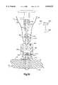
- FIG. 1is a schematic illustration depicting the relationship of a suture retainer to a suture and body tissue prior to tightening of the suture;
- FIG. 2is an enlarged sectional view illustrating the manner in which the suture is wrapped around the suture retainer of FIG. 1 to form bends in the suture;
- FIG. 3is a schematic illustration depicting the manner in which the suture retainer of FIG. 2 is pressed against body tissue with a predetermined force and the manner in which a predetermined force is applied to an outer side surface of the suture retainer to plastically deform the suture retainer;
- FIG. 4is an enlarged fragmentary schematic illustration of a portion of FIG. 3 and depicting the manner in which the material of the suture retainer grips the suture;
- FIG. 6is a schematic pictorial illustration depicting the manner in which a suture is positioned relative to a base of a second embodiment of the suture retainer
- FIG. 7is a schematic illustration, taken along the line 7--7 of FIG. 6, depicting the manner in which a movable arm presses a portion of the suture into a groove formed in the base of the suture retainer to form bends in the suture;
- FIG. 9is a schematic illustration depicting the manner in which a suture is wrapped around another embodiment of the suture retainer to form bends in the suture;
- FIG. 11is a fragmentary sectional view, generally similar to FIG. 10, illustrating an alternative configuration for the groove in the suture retainer of FIG. 9;
- FIG. 13is a schematic illustration depicting another embodiment of the suture retainer and the manner in which sections of a suture are wrapped in opposite directions to form bends in the suture;
- FIG. 14is a sectional view, taken generally along the line 14--14 of FIG. 13, illustrating the manner in which the suture is disposed in a groove in the suture retainer;
- FIG. 15is an enlarged fragmentary schematic illustration of a portion of FIG. 13, further illustrating the manner in which the suture is disposed in grooves formed in the suture retainer;
- FIG. 16is a fragmentary schematic sectional illustration of the manner in which the grooves and sections of the suture of FIG. 15 cross;
- FIG. 17is a schematic sectional view illustrating the manner in which a suture is wrapped around a roller in another embodiment of the suture retainer
- FIG. 19is a fragmentary schematic illustration, generally similar to FIG. 17, depicting an alternative manner of wrapping the suture around the roller;
- FIG. 21is a schematic illustration depicting the manner in which the suture zig-zags through passages in another embodiment of the suture retainer
- FIG. 22is a schematic sectional view, taken generally along the line 22-22 of FIG. 21, further illustrating the manner in which the suture extends through the suture retainer;
- FIG. 23is a schematic sectional view depicting the manner in which the suture zig-zags through passages in another embodiment of the suture retainer;
- FIG. 24is a schematic sectional view illustrating the manner in which turns of a suture are wrapped in loops around another embodiment of the suture retainer
- FIG. 25is a schematic sectional view illustrating the manner in which turns of a suture are wrapped in loops around another embodiment of the suture retainer
- FIG. 27is a pictorial illustration of an inner or lower section of the suture retainer of FIG. 26;
- FIG. 28is a pictorial illustration of an outer or upper section of the suture retainer of FIG. 26;
- FIG. 29is a schematic sectional view of another two-section embodiment of the suture retainer prior to engagement of the two sections of the suture retainer;
- FIG. 32is a schematic sectional illustration depicting the manner in which another embodiment of the suture retainer is pressed against a large area on body tissue with a predetermined force;
- FIG. 33is a schematic view of the suture retainer of FIG. 32 after the suture retainer has been plastically deformed to grip the suture;
- FIG. 35is a schematic illustration of a tool which may be used to press the suture retainer of FIG. 13 against body tissue and to plastically deform the material of the suture retainer;
- a suture retainer 50(FIG. 1) is utilized to secure a known suture 52 against movement relative to body tissue 54.
- the suture 52extends through an outer layer 56 and an inner layer 58 of the body tissue.
- the suture 52has been illustrated schematically in FIG. 1 as extending through passages 60 and 62 in the outer and inner layers 56 and 58 of body tissue 54. However, the suture 52 could be sewn through the body tissue without forming the passages 60 and 62 in the body tissue.
- suture 52has been shown in FIG. 1 in association with soft body tissue, it is contemplated that the suture 52 could be associated with hard body tissue. It is also contemplated that the suture 52 could extend through a suture anchor in a manner similar to that disclosed in U.S. Pat. Nos. 5,584,862; 5,549,631; and/or 5,527,343.
- the sections 66 and 68 of the suture 52could extend straight through the suture retainer 50, it is preferred to form a plurality of bends in the suture 52.
- two bends 72 and 74(FIG. 2) are formed in the left section 66 of the suture 52.
- two bends 76 and 78are formed in the right section 66 of the suture 52. If desired, a greater or lesser number of bends could be formed in each of the sections 66 and 68 of the suture 52.
- the bends 72 and 74are formed in the left section 66 of the suture 52 by wrapping a turn 82 in the left section of the suture around a portion of the suture retainer 50.
- the bends 76 and 78are formed in the right section 68 of the suture 52 by wrapping a turn 84 in the right section of the suture around a portion of the suture retainer 50.
- a single loop 86is formed in the left section 66 of the suture 52 around a portion of the suture retainer.
- a single loop 88is formed in the right section 68 of the suture 52 around a portion of the suture retainer 50.
- a greater or lesser number of loopscould be provided in the left and right sections 66 and 68 of the suture 52 if desired.
- the suture retainer 50has a spherical configuration.
- a cylindrical passage 92extends through the center of the spherical suture retainer 50.
- the suture retainer 50could have a different configuration.
- the suture retainer 50could have an oval or elliptical configuration.
- the passage 92has a linear central axis, the passage could have a nonlinear central axis.
- a plurality of passages, having the same or different configurations,could be provided in the suture retainer 50.
- the left and right sections 66 and 68 of the suture 52extend through the passage 92.
- the left and right sections 66 and 68 of the suture 52extend around a spherical outer side surface 94 of the suture retainer 50.
- the loop 86 in the left section 66 of the suture 52extends around a left (as viewed in FIG. 2) hemispherical portion of the suture retainer 50.
- the loop 88extends around a right hemispherical portion of the suture retainer 50.
- the left and right sections 66 and 68 of the suture 52engage the smooth spherical outer side surface 94 of the suture retainer 50.
- groovescould be provided in the outside of the suture retainer 50 to receive the turns 82 and 84 of the left and right sections 66 and 68 of the suture 52.
- projectionscould extend from the spherical outer side surface 94 of the suture retainer 50 to engage the suture 52.
- the suture retainer 50is moved along the left and right sections 66 and 68 of the suture toward the body tissue 54 (FIG. 1).
- the left and right sections 66 and 68 of the sutureare pulled upward (as viewed in FIGS. 1 and 2) to tension the sections of the suture.
- a downward (as viewed in FIG. 1) forceis then applied against the suture retainer 50. This downward force causes the suture retainer 50 to slide in a downward direction along the suture 52 toward an upper side surface 98 of the body tissue 54 (FIG. 1).
- the suture retainer 50is formed as one piece of a polymeric material having a relatively low coefficient of friction. Therefore, the two sections 66 and 68 of the suture 52 can readily slide along the outer side surface 94 and through the passage 92 in the suture retainer 50 as the suture retainer is moved downward toward the upper side surface 98 (FIG. 1) of the body tissue 54.
- the suture retainer 50is slid downward (as viewed in FIG. 1) along the left and right sections of the suture.
- the suture retainer 50is pressed against the body tissue 54 with a predetermined force 104 (FIG. 3) which is sufficient to obtain a desired tension in the left and right sections 66 and 68 and connector section 102 of the suture 52.
- a desired forcewhich has been preselected, is applied against the body tissue 54 by the suture 52 and suture retainer 50.
- a force distribution member or buttonmay be placed between the suture retainer and the upper surface 98 of the body tissue.
- a second force distribution member or buttonmay be placed between the connector section 102 of the suture and a lower side surface 108 (FIG. 1) of the body tissue 54. If this is done, the main area of engagement of the suture 52 with the body tissue 54 would be at the passages 60 and 62.
- the suture retainer 50is plastically deformed to grip the left and right sections 66 and 68 of the suture.
- a pair of force application members 112 and 114are pressed against opposite sides of the suture retainer 50. The force applied against the suture retainer 50 by the force application members 112 and 114 plastically deforms the material of the suture retainer.
- the plastic deformation of the suture retainer 50is effective to cause cold flowing of material of the suture retainer.
- Force indicated by arrows 118 and 120 in FIG. 3is applied against the suture retainer 50 by the force application members 112 and 114. This force is effective to cause flowing of the material of the suture retainer 50 at a temperature below a transition temperature range for the material of the suture retainer.
- the illustrated force application members 112 and 114have flat force transmitting surfaces, each of the force application members could have force transmitting surfaces with a configuration corresponding to the configuration of a portion of a sphere.
- the cold flowing of the material of the suture retainer 50results in a collapsing of the passage 92 (FIG. 2) and in flowing of the material of the suture retainer 50 around the sections 66 and 68 of the suture 52. This enables the material of the suture retainer 50 to bond to and obtain a firm grip on the suture 52.
- the cold flowing of the material of the suture retainer 50occurs at a temperature which is below the transition temperature of the material forming the suture retainer.
- the material of the suture retainer 50flows around and grips the portion of the suture which was disposed in the passage 92.
- the force applied against the turns 82 and 84 by the force application members 112 and 114is sufficient to embed the turns 82 and 84 of the suture 52 in the material of the suture retainer 50 to further grip the suture.
- the turns 82 and 84are disposed in grooves in the outside of the suture retainer, the material of the suture retainer would more firmly grip the portion of the suture 52 forming the turns 82 and 84.
- groovescould be formed in the cylindrical side surface of the passage 92 to receive the sections 66 and 68 of the suture 52.
- a transducer or load cell 114(FIG. 3) is connected with the force application member 112 to measure the amount of force, indicated by the arrows 118 and 120, which is applied against the suture retainer 50.
- a display unit 126is connected with the load cell 124 and provides an output indicative of the force being applied against opposite sides of the suture retainer 50 by the force application members 112 and 114. After a predetermined minimum force has been applied against the suture retainer 50 for a predetermined minimum time by the force application members 112 and 114, an output from the display unit 126 activates an indicator 130 to indicate to a surgeon that the desired plastic deformation of the suture retainer 50 has occurred. The force application members 112 and 114 can then be withdrawn from the suture retainer 50.
- the suture retaineris pressed against the upper side surface 98 of the body tissue 54 with a predetermined force, indicated at 104 in FIG. 3.
- a predetermined tensionis maintained in sections 66 and 68 of the suture 52 extending upward from the suture retainer 50.
- the application of the clamping forces 118 and 120 against opposite sides of the suture retainer 50causes cold flowing of the material of the suture retainer.
- the material of the suture retainer 50moves between and extends around the portions of the left and right sections 66 and 68 of the suture 52 disposed in the passage 92 (FIG. 2).
- a portion 134 (FIGS. 2 and 4) and a portion 136 of the left section 66 of the suture 52are fully enclosed by the material of the suture retainer 50.
- a cold bonding of the material of the suture retainer 50 with the exterior surfaces of the portions 134 136 of the left section 66 of the suture retainersecurely interconnects the material of the suture retainer and the suture 52.
- the portions 138 and 140 of the right section 68 of the suture 52 disposed in the passage 92are surrounded by and bonded with the material of the suture retainer 50 (FIG. 4).
- the manner in which the material of the suture retainer 50 extends completely around and is connected with the length or portion 138 of the right section 68 of the suture 52is illustrated schematically in FIG. 5. It should be understood that the permanent deformation of the material of the suture retainer 50 occurs as a result of compression of the material of the suture retainer while the material is at a temperature close to the temperature of the body tissue 54. This temperature is below the transition temperature for the material of the suture retainer 50.
- the suturemay be knotted if desired.
- a knotmay be formed between the portions of the sections 66 and 68 of the suture 52 which extend upward (as viewed in FIGS. 1-3) from the retainer 50.
- Such a knotwould provide additional protection against the suture working loose under the influence of varying loads over an extended period of time. Since the suture retainer 50 is disposed between the knot and the body tissue 54, the knot will not reduce the overall force transmitting capability of the suture 52. However, it is believed that forming a knot in the sections 66 and 68 of the suture 52 adjacent to the upper end of the suture retainer 50 will not be necessary.
- the suture retainer 50may be formed of many different materials. However, it is believed that it will be preferred to form the suture retainer 50 of a biodegradable polymer.
- a biodegradable polymerwhich may be utilized is polycaperlactone.
- the suture retainer 50could be formed of polyethylene oxide terephthalate or polybutylene terephthalate. It is also contemplated that other biodegradable or bioerodible copolymers could be utilized if desired.
- the suture retainer 50could be formed of a material which is not biodegradable.
- the suture retainercould be formed of an acetyl resin, such as "Delrin”TM.
- the suture retainer 50could be formed of a para-dimethylamino-benzenediazo sodium sulfonate, such as "Dexon”TM.
- the suture retainer 50could be heated to a temperature which is somewhat above the temperature of the body tissue 54. If desired, heat could be transmitted to the suture retainer 50 through the force application members 112 and 114 (FIG. 3). Although the suture retainer 50 may be heated, the suture retainer would be maintained at a temperature below the transition temperature for the material of the suture retainer.
- the suture 52is separate from the suture retainer 50.
- one of the sections 66 or 68 of the suture 52could be fixedly connected with the suture retainer 50. This could be accomplished with a suitable fastener or by forming the suture 52 integrally as one piece with the suture retainer. This would result in the suture retainer 50 sliding along only one of the sections 66 or 68 of the suture 52.
- the suture 52may be formed of natural or synthetic materials.
- the suture 52may be a monofilament or may be formed of a plurality of interconnected filaments.
- the suture 52may be biodegradable or nonbiodegradable. It may be preferred to form the suture 52 of the same material as the suture retainer 50. However, the suture 52 could be formed of a material which is different than the material of the suture retainer.
- the use of the suture retainer 50eliminates the necessity of forming a knot in the suture 52. By eliminating the formation of a knot in the suture 52, the overall force transmitting capability of the suture is increased. In addition to increasing the overall force transmitting capability of the suture 52, the suture retainer 50 increases the surface area on the body tissue 54 (FIG. 1) against which force is applied by the suture. This tends to minimize any tendency for the suture 52 to cut or separate the body tissue.
- the left and right sections 66 and 68 of the suture 52may be wound around the suture retainer 50 before the suture is positioned in the passages 60 and 62 in the body tissue 54.
- the left section 66 of the suture 52may be wound around the suture retainer 52 to form the bends 72 and 74 and the loop 86 (FIG. 2) while the suture is spaced from the body tissue 54.
- the right section 68 of the sutureis then inserted through the passages 60 and 62 (FIG. 1) in the body tissue 54.
- the right section 68 of the suture 52is then wound around the suture retainer 50 to form the bends 76 and 78 and loop 88 (FIG. 2).
- a suture retainer 150is utilized to secure a suture 52 against movement relative to body tissue.
- the suture 52has sections 66 and 68 which engage body tissue in the same manner as previously described in conjunction with the embodiment of the invention illustrated in FIGS. 1-5.
- the suture 52is illustrated in FIG. 1 in association with soft body tissue, it is contemplated that the suture 52 could be utilized in association with hard body tissue and/or one or more suture anchors.
- the suture retainer 150includes a rectangular base or body section 152 and a movable post or locking section 154.
- the post or locking section 154is integrally formed as one piece with the base 152.
- the post or locking sectionis hingedly connected with the base 152 at a connection 156.
- the post 154is pivotal relative to the base at the connection 156 in the manner indicated schematically by the arrow 158 in FIG. 6.
- the base 152has a central groove 162 which is aligned with the post 154.
- the groove 162has a rectangular cross sectional configuration.
- the groove 162has a cross sectional area which is greater than the cross sectional area of the post 154.
- the post 154 and groove 162both have a rectangular cross sectional configuration.
- the post and groovecould have a different cross sectional configuration if desired.
- the post 154 and groove 162could have a semi-circular cross sectional configuration.
- the post 154When the suture retainer 150 is to be utilized to hold the sections 66 and 68 of the suture 52 against movement relative to body tissue, the post 154 is pivoted from its initial or extended position, shown in FIG. 6, to its engaged or locking position, shown in FIG. 7. As the post 154 is pivoted to the engaged position of FIG. 7, a flat side surface 174 of the post is pressed against the sections 66 and 68 of the suture to force the sections into the groove 162. The post is effective to clamp or hold the sections 66 and 68 of the suture 52 against movement relative to the base 152 upon movement of the post to the engaged position shown in FIG. 7.
- the base 152is bent from the flat orientation of FIGS. 6 and 7 to the folded orientation of FIG. 8.
- a pair of force application members 112 and 114engage opposite sides of the bottom or outer surface 170 of the base. The force application members 112 and 114 are then pressed toward each other, in the manner indicated schematically by the arrows 118 and 120 in FIG. 8, to apply pressure against the suture retainer 150.
- the suture retainer 150is at a temperature below the transition temperature of the material forming the suture retainer.
- the suture retainer 150is at a temperature which is approximately the same as the temperature of the body tissue relative to which the suture retainer 150 is being utilized to secure the suture 52.
- the force applied against the suture retainer 150 by the force application members 112 and 114plastically deforms the material of the suture retainer. This results in a cold flowing of the material of the suture retainer 150 under the influence of the force applied against the suture retainer by the force application members 112 and 114.
- a transducer or load cell 124measures the force 118 and 120 applied against the base 152 of the suture retainer 150.
- the load cell 124provides an output signal to a display unit 126.
- the output signal provided by the transducer 124corresponds to the magnitude of the force applied against opposite sides of the suture retainer 150 by the members 112 and 114.
- an output signal from the display unit 126activates an indicator 130.
- the output from the indicator 130indicates to a surgeon and/or other medical personnel that the force has been applied against opposite sides of the suture retainer 150 by the force application members 112 and 114 for a period of time sufficient to cause cold flowing of the material of the suture retainer.
- the cold flowing of the material of the suture retainer 150results in a secure interconnection between the material of the suture retainer 150 and the sections 66 and 68 of the suture 52.
- the suture 52is separate from the suture retainer 150.
- the suture 52could be fixedly connected to or integrally formed as one piece with the suture retainer 150.
- the base 152could be integrally formed with the section 66 of the suture 52 if desired.
- the sections 66 an d 68 of the suture 52extend through a passage formed in a spherical suture retainer 50.
- the sections of the sutureextend along a groove formed in the outside of a suture retainer. Since the embodiment of the invention illustrated in FIGS. 9-12 is similar to the embodiment of the invention illustrated in FIGS. 1-5, similar terminology will be utilized to identify similar components. It should be understood that one or more features of the embodiments of the invention illustrated in FIGS. 1-8 may be used with the embodiment of the invention illustrated in FIGS. 9-12.
- a suture retainer 180(FIG. 9) is utilized to secure a suture 52 against movement relative to body tissue 54.
- body tissue 54is soft body tissue, it is contemplated that the suture retainer 180 could be utilized to secure the suture 52 against movement relative to hard body tissue, such as bone.
- the suture retainer 180may be used either with or with out a suture anchor.
- the suture retainer 180has a cylindrical main section or body 184.
- the body 184has a cylindrical outer side surface 186.
- Flat circular end surfaces 188 and 190extend perpendicular to a longitudinal central axis of the cylindrical side surface 186.
- the body 184is cylindrical and has a linear longitudinal central axis. If desired, the body 184 could be rectangular and/or have a nonlinear longitudinal central axis.
- a helical groove 194is formed in the body 184.
- the helical groove 194has a constant pitch. Therefore, turns of the groove 194 are equally spaced. However, if desired, the pitch of the turns of the groove 194 could vary along the length of the body 184.
- the helical groove 194has a central axis which is coincident with the central axis of the body 184 and cylindrical outer side surface 186 of the suture retainer 180.
- a radially inner portion of the helical groove 194defines a right circular cylinder which is coaxial with the outer side surface 186 of the body 184.
- the radially inner portion of the helical groove 194could define a right circular cone or other configuration if desired.
- the left and right sections 66 and 68 of the suture 52extend through the groove 194 and around body tissue 54. It is believed that it will be advantageous to provide the helical groove 194 with retainers or bridge sections 198 and 200 which extend across the open ends of the helical groove.
- the bridge sections 198 and 200are integrally formed as one piece with the body 184. The bridge sections 198 and 200 prevent the sections 66 and 68 of the suture 52 from pulling out of the helical groove 194 during positioning of the suture retainer 180 in a human patient's body. However, the bridge sections 198 and 200 may be omitted if desired.
- the helical groove 194has a generally U-shaped cross sectional configuration (FIG. 10).
- the helical groove 194has an open mouth or entrance 204.
- a pair of side surfaces 206 and 208slope radially inward and axially upward (as viewed in FIGS. 9 and 10) from the entrance 204.
- An arcuate bottom surface 210 of the groove 194extends between the side surfaces 206 and 208.
- the section 66 of the suture 52is disposed in engagement with the bottom surface 210 of the helical groove 194.
- the section 68 of the suture 52is disposed in engagement with the section 66 of the suture (FIG. 10). If desired, the size of the arcuate bottom surface 210 of the groove 194 could be increased to enable both sections 66 and 68 of the suture 52 to engage the bottom surface.
- the groove 194may be provided with a configuration similar to the configuration shown in FIG. 11.
- the side surfaces 206 and 208 of the helical groove 194extend inward from the open entrance 204 to an arcuate bottom surface 210 which forms a major portion of a circle.
- the bottom surface 210 of FIG. 11defines a recess 214 in which the two sections 66 and 68 of the suture are disposed. It is believed that the bridge sections 198 and 200 will probably be omitted with the embodiment of the groove 194 illustrated in FIG. 11.
- the cylindrical body 184 of the suture retainer 180is molded from a single piece of a biodegradable polymer.
- the body 184 of the suture retainer 180may be molded from polycaperlactone.
- the body 184 of the suture retainer 180could be molded of polyethylene oxide terephthalate or polybutylene terephthalate.
- the body 184 of the suture retainer 180could be molded as one piece of other biodegradable or bioerodible copolymers if desired.
- the body 184 of biodegradable materialsthe body could be formed of materials which are not biodegradable.
- the body 184could be formed of "Delrin"TM.
- the left and right sections 66 and 68 (FIG. 9) of the suture 52are inserted into the helical groove 194 in the body 184 of the suture retainer 180. At this time, the body 184 of the suture retainer 180 is spaced from the body tissue 54. It is believed that insertion of the left and right sections 66 and 68 of the suture 52 into the helical groove 194 will be facilitated if the bridge sections 198 and 200 are omitted. However, if the bridge sections 198 and 200 are omitted, difficulty may be encountered in maintaining the sections 66 and 68 of the suture 52 in the helical groove 194.
- the left and right sections 66 and 68 of the suture 52are inserted into the helical groove 194 (FIG. 9), the sections of the suture are wrapped around the body 184 of the suture retainer 180. As this occurs, a plurality of helical loops are formed in the left and right sections 66 and 68 of the suture 52.
- a plurality of circular turnsare maintained in the left and right sections 66 and 68 of the suture 52 by the helical groove 194. Therefore, a continuous series of smooth arcuate bends, which are free of stress inducing discontinuities, is maintained in the suture 52 by the helical groove 194.
- the suture retainer 180is moved along the suture toward the body tissue 54 (FIG. 9). During this movement of the suture retainer 180 along the suture 52, the left and right sections 66 and 68 of the suture are tensioned.
- the radially inward and axially upward sloping configuration of the helical groove 194results in the left and right sections 66 and 68 of the suture being pulled toward the arcuate bottom surface 210 of the groove. This results in the body 184 of the suture retainer 180 maintaining the helical loops in the left and right sections 66 and 68 of the suture 52 as the suture retainer 180 moves toward the body tissue 54.
- the left and/or right sections 66 and 68 of the suture 52slide along the arcuate bottom surface 210 (FIG. 10) of the groove 194.
- the groove 194imparts a helical configuration to the portion of the suture 52 disposed in the groove.
- the portion of the suture 52 having a helical configurationmoves downward toward the body tissue.
- the tensioning force in the suturepulls the suture toward the bottom surface 210 of the helical groove 194.
- the biodegradable copolymer forming the body 184 of the suture retainer 180has a low coefficient of friction. This minimizes the force 220 required to move the suture retainer along the left and right sections 66 and 68 of the suture 52 toward the body tissue 54.
- the suture retainer 180is moved along the taut left and right sections 66 and 68 of the suture 52 until the leading end surface 190 of the body 184 of the suture retainer 180 engages the body tissue 54 (FIG. 9).
- the force 220is then increased to a predetermined magnitude while maintaining a predetermined tension in the left and right sections 66 and 68 of the suture 52. This results in the suture 52 being pulled tightly around the body tissue and exerting a predetermined force against the body tissue.
- the magnitude of the force 220(FIG. 9) with which the suture retainer 190 is pressed against the body tissue 54 will be measured to be certain that the force has a desired magnitude.
- the force 220may be measured with a suitable transducer, such as a load cell or a force measuring device having a spring which is compressed to a predetermined extent by the application of the desired force against the body tissue 54.
- a suitable force transmitting membersuch as a button, could be provided between the suture retainer and the body tissue.
- the left and right sections 66 and 68 of the suture 52are gripped by plastically deforming the material of the suture retainer.
- a plurality of force application members 224, 226 and 228are pressed against the cylindrical outer side surface 186 of the suture retainer 180. Since the outer side surface 186 of the suture retainer 180 has a cylindrical configuration, the force application members 224, 226 and 228 have an arcuate configuration and are formed as portions of a circle. However, the force application members 224, 226 and 228 could have the flat configuration of the force application members 112 and 114 of FIG. 3.
- the force application members 224, 226 and 228are pressed against the outer side surface 186 of the suture retainer 180 with a predetermined force, indicated by the arrows 232 in FIG. 12.
- This forcehas a magnitude and is applied for a length of time sufficient to cause cold flowing of the material of the body 184 of the suture retainer 180.
- the plastic deformation of the material of the body 194 of the suture retainer 180results in the helical groove 194 being collapsed and the material of the suture retainer being pressed against the left and right sections 66 and 68 of the suture 52.
- the resulting cold bonding of the material of the suture retainer 180 with the left and right sections 66 and 68 of the suture 52secures in the suture retainer against movement relative to the suture.
- the cold flowing of the material of the body 184 of the suture retainer 180occurs with the body of the suture retainer at substantially the same temperature as the temperature of the body tissue 54 (FIG. 9).
- the cold flowing of the material of the body 184 of the suture retainer 180occurs at a temperature below the transition temperature of the material forming the body 184 of the suture retainer 180.
- some heatmay be added to the body 184 to facilitate plastic deformation of the body of the suture retainer 180.
- the suture retainer 180eliminates the necessity of forming a knot in the suture 52.
- the formation of a knot in the suture 52would cause a stress concentration in the suture and would decrease the overall force transmitting capability of the suture. By eliminating the knot, the overall force transmitting capability of the suture 52 is increased.
- a knotcould be formed in the sections 66 and 68 of the suture 52 at a location above (as viewed in FIG. 9) the suture retainer 180. Since the suture retainer 180 would be disposed between this knot and the body tissue 54, the knot would not decrease the overall force transmitting capability of the suture 52.
- a single helical groove 194is formed in the body 184 of the suture retainer 180. It is contemplated that a pair of spaced apart helical grooves could be formed in the body 184 of the suture retainer 180. If this was done, the two helical grooves would be wrapped in the same direction around the body 184 of the suture retainer 180 and would be offset from each other by 180° about the circumference of the cylindrical body of the suture retainer. The left section 66 of the suture 52 would be disposed in one of the helical grooves and the right section 68 of the suture would be disposed in the other helical groove.
- the left and right sections 66 and 68 of the suture 52would exit from the lower (as viewed in FIG. 9 end of the suture retainer at diametrically opposite locations on the circular end surface 190.
- This embodiment of the suture retainer 180would have the advantage of having a relatively large area of engagement with the body tissue 54. Thus, the tension in the suture would press the flat circular end surface 190 on the suture retainer against the body tissue.
- the suture 52is separate from the suture retainer 180.
- the suture 52could be fixedly connected with or integrally formed as one piece with the suture retainer.
- the left section 66 of the suture 52could be fixedly connected with the body 184 of the suture retainer 180 by a suitable fastener. If this was done, only the right section 68 of the suture 52 would be received in the groove 194.
- the left and right sections 66 and 68 of the suture 52are wrapped in the same direction around the cylindrical body 184 of the suture retainer 180.
- the sections of the sutureare wrapped in opposite directions around a conical body of a suture retainer. Since the embodiment of the invention illustrated in FIGS. 13-16 is similar to the embodiment of the invention illustrated in FIGS. 9-12, similar terminology will be utilized to identify similar components. It should be understood that one or more features of the embodiments of the invention illustrated in FIGS. 1-12 may be used with the embodiments of the invention illustrated in FIGS. 13-16.
- a suture 52(FIG. 13) has left and right sections 66 and 68 which are wrapped in opposite directions around a conical body 242 of a suture retainer 244.
- the left section 66 of the suture 52is wrapped in a counterclockwise direction around the body 242 of the suture retainer 244.
- the right section 68 of the suture 52is wrapped in a clockwise direction around the body 242 of the suture retainer 244.
- the left and right sections 66 and 68 of the suture 52are wrapped for approximately 11/2 turns around the body 242 of the suture retainer 244. Therefore, the left section 66 of the suture 52 moves from the left side of the upper end (as viewed in FIG. 13) of the body 242 of the suture retainer 244 to the right side of the lower end of the body of the suture retainer. Similarly, the right section 68 of the suture 52 moves from the upper right side of the body 242 of the suture retainer 244 to the lower left side of the body of the suture retainer.
- the sections of the suture 52would be on the same side of the body 242 at the top and bottom of the suture retainer.
- the left section 66 of the suture 52would be disposed at the left side of both the upper and lower ends of the body 242.
- the right section 68 of the suture 52could be disposed at the right side of both the upper and lower ends of the body 242 of the suture retainer.
- the body 242 of the suture retainer 244is formed as a portion of a right circular cone.
- the body 242 of the suture retainer 244has an outer side surface 248 with an axially downward (as viewed in FIG. 13) and radially inward tapering configuration.
- the conical body 242 of the suture retainer 244has parallel circular end surfaces 252 and 254 which extend perpendicular to a longitudinal central axis of the conical body.
- the circular end surfaces 252 and 254are disposed in a coaxial relationship.
- the upper end surface 252has a larger diameter than the lower end surface 254.
- a pair of helical grooves 258 and 260are formed in the conical body 242.
- the helical grooves 258 and 260have a spiral configuration with a central axis which is coincident with the central axis of the conical body 242.
- the diameter of the turns of the grooves 258 and 260progressively decreases as the grooves extend downward (as viewed in FIG. 13) from the upper end surface 252 to the lower end surface 254.
- the helical grooves 258 and 260have the same pitch.
- the helical grooves 258 and 260are wrapped in opposite directions around the conical body 242 of the suture retainer 244.
- the helical groove 258is wrapped in a counterclockwise direction around the body 242 of the suture retainer 244.
- the helical groove 260is wrapped in a clockwise direction around the body 242 of the suture retainer 244.
- the helical grooves 258 and 260are offset by 180°.
- the helical groove 258beings at the upper left (as viewed in FIG. 13) side of the body 242 and the helical groove 260 begins at the upper right side of the body 242.
- the entrances to the helical grooves 258 and 260are disposed at diametrically offset locations on the circular upper end surface 252 of the body 242.
- the helical groove 258ends at the lower right (as viewed in FIG. 13) side of the body 242.
- the helical groove 260ends at the lower left side of the body 242.
- the exits from the helical grooves 258 and 260are disposed at diametrically offset locations on the circular lower end surface 254 of the body 242. This results in the relatively large lower end surface 254 of the body 242 being disposed between the left and right sections 66 and 68 of the suture 52 and exposed to body tissue.
- the groove 258has an axially upward and radially inward sloping configuration (FIG. 14).
- the groove 258has a helical open mouth or entrance 264.
- the groove 258has a pair of axially upward and radially inward sloping side surfaces 266 and 268.
- the side surfaces 266 and 268are interconnected by an arcuate bottom surface 270.
- the groove 258has the same depth and cross sectional configuration throughout the extent of the groove.
- the groove 260has the same cross sectional configuration as the groove 258.
- the two grooves 258 and 260extend between the opposite end surfaces 252 and 254 of the conical body 242. It is contemplated that the grooves 258 and 260 could have a different cross sectional configuration if desired. For example, the grooves 258 and 260 could have the cross sectional configuration shown in FIG. 11 if desired.
- the grooves 258 and 260intersect on opposite sides of the conical body 242 in the manner illustrated in FIGS. 15 and 16. At the intersections between the grooves 258 and 260, the left and right sections 66 and 68 of the suture 52 overlap (FIG. 16). The number of intersections of grooves 258 and 260 will vary as a direct function of the number of turns of the grooves 258 and 260 around the body 242.
- Bridge sections 274 and 276are provided across opposite ends of the groove 258 to facilitate in retaining the suture section 66 in the groove.
- bridge sections 278 and 280are provided across opposite ends of the groove 260 to facilitate in retaining the suture section 68 in the groove 260. If desired, the bridge sections 274, 276, 278 and 280 could be omitted.
- the suture retainer 244includes a cylindrical sleeve 284 (FIG. 13).
- the tubular sleeve 284has a cylindrical outer side surface 286 and a conical inner side surface 288.
- the inner and outer side surfaces 286 and 288are disposed in coaxial relationship.
- the conical inner side surface 288 of the sleeve 284tapers axially inward and downward (as viewed in FIG. 13) at the same angle as does the conical outer side surface 248 of the body 242.
- the conical inner side surface 288 of the sleeve 284has been schematically illustrated in FIG. 13 as having an inside diameter which is greater than the outside diameter of the conical body 242, it is contemplated that the conical body 242 will have substantially the same diameter as the inner side surface 288 of the sleeve 284. Therefore, when the circular end surface 252 on the conical body 242 is axially aligned with an annular end surface 292 on the sleeve 284 (as shown in FIG. 13), the outer side surface 248 on the conical body 242 will be disposed in abutting engagement with the inner side surface 288 on the sleeve 286.
- the conical body 242 and the sleeve 284are both formed of a biodegradable polymer, such as polycaperlactone.
- the conical body 242 and the sleeve 284could be formed of polyethylene oxide terephthalate or polybutylene terephthalate if desired.
- Other biodegradable or bioerodible copolymerscould be utilized if desired. It is contemplated that it may be desired to form the conical body 242 and sleeve 284 of a polymer which is not biodegradable.
- the conical body 242 and sleeve 284could be formed of two different materials if desired.
- the left and right sections 66 and 68 of the sutureare first inserted through the open center of the sleeve 284.
- the sections 66 and 68 of the suture 52are then wrapped around the conical body 242 in the grooves 258 and 260.
- the sleeve 284may then be moved along the suture 252 to the desired position in a patient's body.
- one of the sections 66 or 68 of the suture 52may be wound around the body 242 and inserted through the sleeve 284 before the suture is positioned relative to the body tissue. After the suture 52 has been positioned relative to the body tissue, the other section of the suture would be inserted upward (as viewed in FIG. 13) through the sleeve 284 and wound around the body 242.
- the sections 66 and 68 of the suture 52are tensioned as a force 296 (FIG. 13) is applied to the conical body 242.
- the force 296is sufficient to cause the conical body 242 of the suture retainer 244 to slide axially along the sections 66 and 68 of the suture toward the sleeve 284.
- the conical body 242moves into telescopic engagement with the sleeve 284.
- the force 296is then effective to press the outer side surface 248 on the conical body 242 firmly against the inner side surface 288 of the sleeve.
- the force 296is also effective to press both the end surface 254 of the conical body 242 and an annular end surface 300 of the sleeve 284 against the body tissue. While the left and right sections 66 and 68 of the suture are tensioned, the force 296 is increased.
- force applicator memberssimilar to the force applicator members 224, 226 and 228 of FIG. 12, compress the sleeve 284.
- the manner in which force is applied against the sleeve 284is indicated schematically by arrows 302 and 304 in FIG. 13. If desired, one or more axial slots may be provided through a portion of the sleeve 284 to facilitate compression of the sleeve.
- the force applied against the sleeve 284, indicated schematically at 302 and 304,causes radially inward plastic deformation of the sleeve. This force is transmitted through the sleeve to the conical body 242.
- the force transmitted to the conical body 242causes a collapsing of the grooves 258 and 260. As the grooves 258 and 260 collapse, the material of the conical body 242 is plastically deformed and firmly grips or bonds to the outer side surfaces of the left and right sections 66 and 68 of the suture 52.
- the sleeve 284 and conical body 242 of the suture retainer 244are at a temperature below the transition temperature of the material forming the sleeve and conical body when they are compressed by the force indicated schematically at 302 and 304 in FIG. 13. This results in cold flowing of the material of both the sleeve 284 and the suture retainer 244 under the influence of the force 302 and 304.
- the force 302 and 304is maintained at a predetermined magnitude for a time sufficient to result in cold plastic deformation of the material of the sleeve 284 and conical body 242.
- This plastic deformation or cold flow of the material of the sleeve 284 and conical body 242occurs at a temperature which is substantially the same as the temperature of the body tissue with which the suture 52 is connected.
- both the conical body 242 and sleeve 284are at a temperature below the transition temperature of the material of the conical body and sleeve.
- the suturemay be knotted.
- a knotmay be formed in the upper (as viewed in FIG. 13) end portions 66 and 68 of suture 52.
- the knotwould pull the sections 66 and 68 of the suture firmly against the upper side surface 252 of the conical body 242.
- This knotwould not decrease the overall force transmitting capability of the suture 52 since the suture retainer 244 is disposed between the knot and the body tissue. Although such a knot would provide additional assurance that the suture will not work loose, it is believed that the knot is not necessary.
- the tension in the suture 52will press the annular end surface 300 on the sleeve 284 and the circular end surface 254 on the conical body 242 against the body tissue. Due to the relative large combined area of the end surfaces 254 and 300, the tension forces in the suture 52 will be applied to a relatively large area on the body tissue by the suture retainer 244. Since the suture retainer 244 applies force to a relatively large surface area on the body tissue and since the overall strength of the suture 52 is not impaired by the suture retainer 244, relatively large forces can be transmitted through the suture to the body tissue.
- the helical grooves 258 and 260cross. This results in the left and right sections 66 and 68 of the suture 52 being disposed in overlapping engagement at the intersections between the grooves 258 and 260. The overlapping engagement of the left and right sections 66 and 68 of the suture 52 increases the resistance of the suture retainer 244 to slipping of one section of the suture relative to the other section of the suture.
- the central axis of the conical body 242 of the suture retainer 244extends along the sections 66 and 68 of the suture 52.
- a central axis of a circular body of the suture retainerextends transverse to the longitudinal axis of the suture during movement of the suture retainer toward the body tissue. Since the suture retainer of the embodiments of the invention illustrated in FIGS. 17-19 is similar to the suture retainer of the embodiment of the invention illustrated in FIGS. 13-16, similar terminology will be utilized to identify similar components. It should be understood that one or more features of the embodiments of the invention illustrated in FIGS. 1-16 may be used with the embodiments of the invention illustrated in FIGS. 17-19.
- a suture retainer 312(FIGS. 17 and 18) includes a cylindrical housing 314 and a rotatable cylinder 316.
- the housing 314encloses the rotatable cylinder 316.
- the rotatable cylinder 316has a central axis which is coincident with the central axis of the cylindrical housing 314.
- the cylinder 316is supported for rotation relative to the housing 314 by bearing sections 320 and 322 (FIG. 17).
- the bearing sections 320 and 322are integrally formed as one piece with the housing 314.
- the bearing sections 320 and 322have a conical configuration and engage conical recesses formed in opposite ends of the rotatable cylinder 316.
- the bearing sections 320 and 322support the cylinder 316 in a coaxial relationship with the housing 314.
- Left and right sections 66 and 68 of the suture 52extend into the housing 314 through cylindrical openings 326 and 328.
- the sections 66 and 68 of the suture 52extend from the housing 314 through openings 330 and 332.
- the openings 326, 328, 330 and 332have parallel central axes which extend tangentially to the cylinder 316.
- the left section 66 of the suture 52extends through the opening 326 into the housing 314.
- the left section 66 of the suture 52is wrapped in a clockwise direction (as viewed in FIG. 18) around the cylinder 316 and extends from the housing 314 through the opening 330.
- the right section 68 (FIG. 17) of the suture 52extends into the housing 314 through the opening 328.
- the right section 68 of the suture 52is wrapped in a counterclockwise direction, as viewed in FIG. 18, around the cylinder 316.
- the turns in the left and right sections 66 and 68 in the suture 52are axially spaced apart along the cylindrical outer side surface of the cylinder 316. If desired, helical grooves may be provided in the cylinder 316 to receive the turns of the left and right sections 66 and 68 of the suture 52.
- the cylindrical housing 314is formed of a biodegradable polymeric material.
- the cylinder 316is also formed of a biodegradable polymeric material.
- the material of the cylinder 316is harder than the material of the housing 314.
- the material of the cylinder 316has a lower coefficient of friction than the material of the housing 314.
- the material of the housing 314is easier to plastically deform than the material of the cylinder 316.
- the housing and cylinder 314 and 316may be formed of the same material which may be biodegradable (polycaperlactone) or may not be biodegradable.
- the suture retainer 312When the suture retainer 312 is to be positioned relative to body tissue (not shown), the left and right sections 66 and 68 of the suture are tensioned. The housing 312 is then pushed downward (as viewed in FIGS. 17 and 18) in the manner indicated schematically by an arrow 336 in FIG. 18. As this occurs, the turns or wraps of the sections 66 and 68 of the suture slide along a cylindrical outer side surface of the rotatable cylinder 316. The oppositely wound loops in the sections 66 and 68 of the suture 52 move downward along the suture toward the body tissue as the retainer 312 moves downward along the suture toward the body tissue.
- the position of the cylinder 316 relative to the housing 314remains substantially constant during at least a portion of the movement of the suture retainer 312 along the suture 52 toward the body tissue. This is because the left and right sections 66 and 68 of the suture are wrapped in opposite directions around the cylinder 316. This results in the portion of the loop in the left section 66 of the suture tending to rotate the cylinder 316 in a counterclockwise direction (as viewed in FIG. 18). At the same time, the loop formed in the right section 68 of the suture 52 tends to rotate the cylinder 316 in a clockwise direction (as viewed in FIG. 18).
- the tensionis maintained in the sections 66 and 68 of the suture 52.
- the force 336(FIG. 18) pressing the suture retainer 312 against the body tissue is increased.
- the suture retainer 312is pressed against the body tissue with a force, indicated schematically by the arrow 336 in FIG. 18, which is sufficient to provide a desired tension in the portion of the suture 52 engaging the body tissue.
- the material of the suture retainer 312is then plastically deformed.
- the plastic deformation of the suture retainer 312is accomplished by applying force against opposite sides of the housing 314 with a pair of force application members 340 and 342 (FIG. 18).
- the force applied against the suture retainer 312 by the force application members 340 and 342presses the material of the housing 314 against the sections 66 and 68 of the suture and the cylinder 316 by cold flowing material of the housing.
- a large gaphas been shown between the cylindrical outer side surface of the cylinder 316 and a cylindrical inner side surface of the housing 314 in FIG. 18.
- this annular gapwill be relatively small so that the material of the housing 314 can readily cold flow into engagement with the turns of the sections 66 and 68 of the suture 52 and cylinder 316.
- the force applied against the housing 314also plastically deforms and causes cold flowing of the material of the cylinder 316 to provide a secure bond or grip between the material of the cylinder 316 and the suture 52.
- a transducer or load cell 346is associated with the force application member 342 and provides an output to a display unit 348. After a predetermined minimum force has been applied to the suture retainer 312 by the force application members 340 and 342 for a predetermined minimum length of time, an output from the display unit 348 to an indicator 350 activates the indicator to provide a signal that the desired plastic deformation of the suture retainer 312 has been obtained.
- a knotmay be tied between the left and right sections 66 and 68 of the suture 52 adjacent to a side of the housing 314 opposite from a side of the housing which is pressed against the body tissue by the suture. The knot would be pulled tight against the housing at a location between the openings 326 and 328. Since the suture retainer 312 is between the knot and the body tissue, the knot would not impair the force transmitting capability of the suture 52.
- the sections 66 and 68 of the suture 52are wrapped in opposite directions around the cylinder 316. This results in offsetting forces being applied to the cylinder 316 by the turns in the sections 66 and 68 of the suture 52 during movement of the suture retainer 312 along the suture toward the body tissue.
- the left and right sections 66 and 68 of the suture 52are wrapped in the same direction around the cylinder 316. This results in the turns or loops in the sections 66 and 68 of the suture 52 applying force to the cylinder 316 urging the cylinder to rotate in the same direction during movement of the suture retainer 312 along the sections 66 and 68 of the suture toward body tissue. Therefore, when the sections 66 and 68 of the suture 52 are wrapped in the same direction around the cylinder 316, the cylinder will freely rotate relative to the housing 314 as the suture retainer 312 is moved along the suture 52 toward the body tissue.
- the overall force transmitting capability of the suture 52is not impaired by the suture retainer 312. This is because the turns of the loops formed in the left and right sections of the suture 52 around the cylinder 316 do not form stress concentrations in the suture. If a knot had been used to interconnect the left and right sections 66 and 68 of the suture 52, in the manner taught by the prior art, the resulting stress concentration would reduce the overall force transmitting capability of the suture 52.
- the cylindrical housing 314increases the surface area on body tissue against which force is applied by tension in the suture 52 after the suture retainer 312 has been plastically deformed to grip the suture. This increases the amount of force which may be transmitted through the suture 52 without damaging the body tissue.
- the cylinder 316is rotatable relative to the housing 314.
- cylindersare fixedly connected with a housing. Since the embodiment of the invention illustrated in FIG. 20 is similar to the embodiment of the invention illustrated in FIGS. 17-19, similar terminology will be utilized to identify similar components. It should be understood that one or more features of the embodiments of the invention illustrated in FIGS. 1-19 may be used with the embodiment of the invention illustrated in FIG. 20.
- a suture retainer 356includes a rectangular housing 358 which encloses a plurality of cylinders 360, 362, 364 and 366.
- the cylinders 360-366have parallel central axes which extend parallel to flat rectangular upper and lower side walls 370 and 372 of the housing 358. Opposite end portions of the cylinders 360-366 are fixedly connected with rectangular end walls (not shown) of the housing 358.
- the central axes of the cylinders 360-366extend perpendicular to the housing end walls to which the cylinders are fixedly connected.
- the cylinders 360-366are formed of a biodegradable material which is relatively hard.
- the housing 358is formed of a biodegradable material which is relatively soft. By forming the housing 358 of a biodegradable material which is relatively soft, plastic deformation of the housing is facilitated.
- the relatively hard biodegradable material forming the cylinders 360-366has a low coefficient of friction.
- the cylinders and housingcould be formed of biodegradable or nonbiodegradable materials having the same hardness if desired.
- a suture 52has left and right sections 66 and 68 which are wrapped around the cylinders 360-366 in a zig-zag fashion.
- the left section 66 of the suture 52is looped around the cylinders 360 and 362.
- the right section 68 of the suture 52is looped around the cylinders 364 and 366.
- the cylinders 360 and 362maintain a pair of smooth, continuous bends in the left section 66 of the suture 52.
- the cylinders 364 and 366maintain a pair of smooth, continuous bends in the right section 68 of the suture 52.
- the smooth, continuous bends in the sections 66 and 68 of the suture 52are free of stress inducing discontinuities. If desired, a greater or lesser number of bends could be maintained in the sections 66 and 68 of the suture 52 by a greater or lesser number of cylinders.
- FIG. 20there is a single partial turn of the left section 66 of the suture around each of the cylinders 360 and 362.
- a plurality of turns or loopscould be provided around each of the cylinders 360-366 by the sections 66 and 68 of the suture 52.
- the left section 66 of the suture 52could be wrapped for one complete revolution around the cylinder 360 and then wrapped for a partial revolution around the cylinder 360 before extending to the cylinder 362.
- the right section 68 of the suture 52could be wrapped for one complete revolution around the cylinder 366 and then wrapped for a partial revolution around the cylinder 364 before exiting from the housing 358.
- the suture retainer 356is moved along the sections 66 and 68 of the suture 52 toward body tissue.
- the housing 358is moved downward (as viewed in FIG. 20), toward the body tissue, the left and right sections 66 and 68 of the suture 52 slide along the outer side surfaces of the cylinders 360-366.
- the cylinders 360-366cooperate to maintain a plurality of bends in each of the sections 66 and 68 of the suture 52.
- the housing 358is plastically deformed to grip the suture 52.
- forceindicated by arrows 380 and 382 in FIG. 20 supplied against a side of the housing 358 opposite from the force 376. This force is effective to plastically deform the material of the housing and to press the material of the housing against the cylinders 360-366 and against the sections 66 and 68 of the suture 52.
- the material of the housingcold flows under the influence of the force.
- This cold flow of the material of the housingresults in the left and right sections 66 and 68 of the suture being firmly pressed against the cylinders 360-366 to form a solid bond with the left and right sections 66 and 68 of the suture 52.
- the material forming the cylinders 360-366is relatively hard, compared to the material forming the housing 358, the housing will deform to a greater extent than the cylinders during cold flow of the material of the housing. However, there will be some plastic deformation of the cylinders 360-366.
- the force transmitting capability of the suture 52is enhanced by minimizing stress concentrations in the suture and by transmitting force from the housing 358 to a large area on the body tissue.
- the bends formed in the suture 52 around the cylinders 360-366are free of abrupt stress inducing discontinuities.
- the housing 358transmits force to the body tissue located between the opposite sides of the left and right sections 66 and 68 of the suture 52. Therefore, stress concentrations in both the body tissue and the suture 52 tend to be minimized.
- a knotmay be tied between the upper (as viewed in FIG. 20) end portions of the left and right sections 66 and 68 of the suture 52. Although such a knot would provide additional assurance that the suture 52 will not work loose, it is believed that the knot will not be necessary.
- One of the ends of the suture 52could be fixedly connected with the housing 358. This could be done by forming the suture 52 as one piece with the housing 358 or by using a fastener. If one end of the suture is fixedly connected with the housing 358, one of the sets of cylinders, for example, the cylinders 360 and 362, could be eliminated.
- bendsare formed in the left and right sections 66 and 68 of the suture 52 by circular surfaces.
- the bendsare formed in the suture by passages through a rectangular member. Since the embodiment of the invention illustrated in FIGS. 21 and 22 is similar to the embodiment of the invention illustrated in FIGS. 9-20, similar terminology will be utilized to identify similar components. It should be understood that one or more of the features of the embodiments of the invention illustrated in FIGS. 1-20 may be used with the embodiment of the invention illustrated in FIGS. 21-22.
- a suture retainer 390is formed of a single rectangular piece of biodegradable material.
- the suture retainer 390includes a rectangular body 392 formed of a suitable biodegradable material.
- the rectangular body 392could be formed of a non-biodegradable material if desired.
- a plurality of parallel passages 394, 396 and 398extend between opposite parallel rectangular end surfaces 400 and 402 of the body 392.
- the left and right sections 66 and 68 of the suture 52zig-zag through the passages 394, 396 and 398 in a side-by-side relationship.
- the sections 66 and 68 of the suture 52zig-zag through the passages 394, 396 and 398 to form a series of bends in the suture.
- the passages 394, 396 and 398 in the body 392 of the suture retainer 390cooperate to form smooth, continuous bends 406, 408, 410 and 412 (FIG. 21) in the sections 66 and 68 of the suture 52.
- the left and right sections 66 and 68 of the suture 52extend through the straight passage 394.
- Bends 406 and 408are formed in the portions of the sections 66 and 68 of the suture disposed between the passage 394 and the passage 396.
- bends 410 and 412are formed in the sections 66 and 68 of the suture 52 disposed between the passages 396 and 398.
- additional bendswould be formed in the suture 52.
- the bends 406-412 in the sections 66 and 68 of the suture 52are smooth and free of stress inducing discontinuities. By keeping the suture 52 free of stress inducing discontinuities, the force which can be transmitted through the suture tends to be maximized. If a knot was substituted for the suture retainer 390, stress concentrations would be formed and the force transmitting capability of the suture reduced.
- the passage 394has a main section 418 and a gripping section 420.
- the gripping section 420has a tapered configuration (FIG. 22) and extends sideward from the main section 418.
- the left and right sections 66 and 68 of the suture 52may be pulled from the main section 418 of the passage 394 into the gripping section 420 of the passage. As this occurs, the side surfaces of the passage 394 grip opposite sides of the left and right sections 66 and 68 of the suture 52 to hold the left and right sections of the suture against axial movement relative to the rectangular body 392 of the suture retainer 390.
- the suture retainer 390is formed of a single piece of biodegradable material, such as polycaperlactone. Of course, other suitable biodegradable or bioerodible materials could be utilized if desired. It is contemplated that the suture retainer 390 could be formed of materials which do not biodegrade.
- the suture retaineris moved along the suture toward body tissue (not shown).
- the side-by-side sections 66 and 68 of the sutureslide in the same direction on surfaces of the suture retainer 390.
- the force indicated schematically by the arrow 424is increased to a predetermined force.
- a predetermined tensioning forceis applied to the left and right sections 66 and 68 of the suture 52. This results in the suture 52 being pulled tight to grip the body tissue with a desired force.
- the rectangular end surface 402 on the body 392 of the suture retainer 390distributes the tension force in the suture 52 over a relatively large area on the body tissue.
- the left and right sections 66 and 68 of the suture 52may be pulled towards the right (as viewed in FIGS. 21 and 22). As this occurs, the left and right sections 66 and 68 of the suture 52 will move from the main section 418 of the passage 394 into the gripping section 420 of the passage. This results in a frictional grip between the retainer body 392 and the suture 52 to hold the suture against movement relative to the retainer body and to maintain the desired tension in the suture.
- the passages 394, 396 and 398are collapsed and the material of the body 392 of the suture retainer 390 cold flows around and grips the left and right sections 66 and 68 of the suture 52.
- the plastic deformation of the body 392 of the suture retainer 390occurs at a temperature below the transition temperature of the material forming the suture retainer. If desired, the suture retainer 390 could be heated to promote cold flow of the material of the suture retainer.
- the gripping section 420mechanically grips a portion of the suture 52.
- the gripping section 420could be eliminated and the suture moved into engagement with a projection from the body 392.
- the upper (as viewed in FIG. 21) portions of the suture 52could be wrapped around a projection from the body 392.
- the upper (as viewed in FIG. 21) portions of the suturecould be moved into engagement with one or more hook-shaped locking notches on the body 392 of the suture retainer 390.
- the left and right sections 66 and 68 of the suture 52extend through the passages 394, 396 and 398 in a side-by-side relationship.
- loopsare formed in the left and right sections of the suture around portions of the suture retainer. Since the embodiments of the invention illustrated in FIGS. 23-25 is similar to the embodiment of the invention illustrated in FIGS. 21-22, similar terminology will be utilized to identify similar components. It should be understood that one or more features of the embodiments of the invention illustrated in FIGS. 1-22 could be used with the embodiments of the invention illustrated in FIGS. 23-25.
- a suture retainer 440(FIG. 23) has a rectangular body 442.
- a plurality of straight parallel cylindrical passages 444, 446 and 448extend between flat parallel rectangular end surfaces 450 and 452 of the rectangular body 442 of the suture retainer 440.
- the left and right sections 66 and 68 of the suture 52extend through the passages 444, 446 and 448 in a zig-zag manner.
- the left section 66 of the suture 52zig-zags through the passages 444, 446 and 448 in the rectangular body 442 of the suture retainer 440.
- the left section 66 of the suture 52is first moved downward (as viewed in FIG. 23) through passage 448.
- a smooth, continuous first bend 456is then formed in the left section 66 of the suture 52 and the left section is moved upward through the passage 446.
- a smooth, continuous second bend 458is then formed in the left section 66 of the suture 52.
- the left section 66 of the suture 52is then moved downward through the passage 444.
- the right section 68 of the suture 52is also inserted into the suture retainer 440 in a zig-zag fashion.
- the right section 68 of the suture 52is moved downward through the passage 444.
- a smooth, continuous first bend 462is formed in the right section 68 of the suture 52.
- the right section 68 of the suture 52is then moved upward through the passage 446.
- a smooth, continuous second bend 464is then formed in the right section 68 of the suture 52.
- the right section 68 of the suture 52is then moved downward through the passage 448.
- the left and right sections 66 and 68 of the suture 52are not aligned or in a side-by-side relationship with each other.
- the bends 456 and 458 in the left section 66 of the suture 52are offset from the bends 462 and 464 in the right section 68 of the suture 52.
- the bends 456, 458, 462, and 464are free of stress inducing discontinuities which would tend to weaken the suture 52.
- the left and right sections 66 and 68 of the sutureare tensioned and force is applied to the rectangular body 442 of the suture retainer 440 to move the suture retainer along the suture 52 toward the body tissue.
- the left and right sections 66 and 68 of the suture 52slide in opposite directions along the surfaces of the passages 444, 446 and 448. As this occurs, the zig-zag portion of the suture 52 is moved along the suture toward the body tissue.
- the suture retainer 440When the rectangular leading end surface 452 of the body 442 of the suture retainer 440 moves into engagement with the body tissue, the suture retainer is pressed against the body tissue with a predetermined force while maintaining a predetermined tension in the left and right sections 66 and 68 of the suture. The suture retainer 440 is then plastically deformed to grip the left and right sections 66 and 68 of the suture 52. To plastically deform the material of the suture retainer 440, force is applied against opposite sides of the suture retainer 440, in the manner indicated by arrows 470 and 472 in FIG. 23.
- the force indicated by the arrows 470 and 472causes cold flow of the material of the suture retainer 440.
- the suture retainer 440is formed from a single piece of biodegradable polymeric material, such as polycaperlactone.
- the plastic deformation of the suture retainer 440occurs while the material of the suture is a temperature which is below the transition temperature of the material and is at a temperature close to the temperature of the body tissue.
- the suture retainer 440could be heated to a temperature above the temperature of the body tissue and below the transition temperature of the material of the suture retainer to promote cold flow of the material of the suture retainer.
- a suture retainer 480includes a rectangular body 482 formed of a biodegradable polymeric material.
- a plurality of straight cylindrical passages 484, 486 and 488extend between and are perpendicular to flat parallel end surfaces 492 and 494 on the rectangular body 482 of the suture retainer 480.
- the suture 52includes left and right sections 66 and 68.
- the left and right sections 66 and 68are wrapped, in zig-zag fashion, around portions 498 and 500 of the rectangular body 482. This results in the formation of left and right loops 502 and 504 in the left and right sections 66 and 68 of the suture 52.
- the loops 502 and 504are free of stress inducing discontinuities.
- the left and right sections 66 and 68 of the suture 52are tensioned with a predetermined force. Force is then applied to the rectangular body 482 of the suture retainer to move the suture retainer downward (as viewed in FIG. 24) along the suture 52. As this occurs, the left and right sections 66 and 68 slide along surfaces of the passages 484, 486 and 488. In addition, the loops 502 and 504 move downward (as viewed in FIG. 4) along the suture 52.
- the leading end surface 494 of the rectangular body 482is pressed against the body tissue with a predetermined force while a predetermined tension is maintained in the left and right sections 66 and 68 of the suture 52.
- the material of the suture retainer 480is then plastically deformed to grip the left and right sections 66 and 68 of the suture 52.
- the material of the suture retainer 480is plastically deformed, the material of the suture retainer is below its transition temperature and is at a temperature close to the temperature of the body tissue. Therefore, the material of the suture retainer 480 cold flows under the influence of force applied against the suture retainer to collapse the passages 484, 486 and 488 and grip the left and right sections 66 and 68 of the suture 52.
- the flat rectangular end surface of the suture retainer 480applies force over a relatively large surface area on the body tissue. This reduces any tendency for the suture 52 to cut or separate the body tissue.
- the force which can be transmitted through the suture 52is maximized by eliminating sharp bends in the suture. If the suture retainer 480 was eliminated and the suture was secured with a knot, the suture would be weakened by stress concentrations formed at sharp bends in the knot.
- a suture retainer 510includes a rectangular body 512 formed of a biodegradable polymeric material.
- a plurality of straight parallel cylindrical passages 514, 516, 518, and 520extend between flat rectangular end surfaces 522 and 524 of the body 512.
- the suture 52includes left and right sections 66 and 68. Separate left and right loops 530 and 532 (FIG. 25) are formed in the sections 66 and 68 of the suture 52.
- the left loop 530 in the left section 66 of the suture 52extends through the passages 518 and 520 in the rectangular body 512 of the suture retainer 510.
- the right loop 532extends through the passages 514 and 516 in the rectangular body 512 of the suture retainer 510.
- the left and right sections 66 and 68 of the suture 52are tensioned. Force is then applied to the suture retainer 510 to move the suture retainer downward (as viewed in FIG. 25) along the suture 52 into engagement with the body tissue.
- the biodegradable polymeric material of the suture retainer 510is plastically deformed by applying force against the suture retainer and cold flowing the material of the suture retainer. Cold flow of the material of the body 512 collapses the passages 514-520. The material of the body 512 then firmly grips the suture 52.
- a knotmay be tied between the upper portions of the suture. This knot would be pressed tightly against the upper end surface 522 of the rectangular body 512 of the suture retainer 510. This knot would be disposed at a location between the locations of the passages 516 and 518 before plastic deformation of the body 512 of the suture retainer 510. It is believed that such a knot may not be necessary.
- the passages through the rectangular bodies of the suture retainerare shorter than the passages through the rectangular body of the suture retainer illustrated in FIG. 23.
- the passages through the rectangular bodies of the suture retainers illustrated in FIGS. 24 and 25could have a longer length if desired.
- the suture 52is separate from the suture retainers 440, 480 and 510.
- one end of the suture 52could be connected with any one of he suture retainers 440, 480 and 510. If this was done only one of the sections 66 or 68 would be zig-zagged through passages in a suture retainer.
- an end of the left section 66 of the suture 52may be fixedly connected with one of the suture retainers 440, 480 or 510. Only the right section 68 of the suture 52 would have to be inserted through the passages in the one suture retainer 440, 480 or 510.
- the end of the suture 52could be fixedly connected with a suture retainer 440, 480 or 510 by a suitable fastener or by forming the suture as one piece with the suture retainer.
- the suture retaineris formed form a single piece of biodegradable polymeric material.
- the suture retaineris formed from a plurality of pieces of biodegradable polymeric material. Since the embodiment of the invention illustrated in FIGS. 26-28 is similar to the embodiment of the invention illustrated in FIGS. 21-25, similar terminology will be utilized to identify similar components. It should be understood that one or more of the features of the embodiments of the invention illustrated in FIGS. 1-25 could be used with the embodiment of the invention illustrated in FIGS. 26-28.
- a suture retainer 540(FIG. 26) includes a base 542 (FIGS. 26 and 27) and a sleeve or cap 544 (FIGS. 26 and 28).
- the base 542has a circular flange 548 which extends radially outward from an upstanding central or post portion 550 (FIGS. 26 and 27).
- the post portion 550has a generally cylindrical configuration and is disposed in a coaxial relationship with the circular flange 548.
- the flange 548 and post portion 550are integrally formed from one piece of a biodegradable material, such as polycaperlactone.
- the base 542 and/or the cap 544could be formed of a material which is not biodegradable.
- a pair of passages 554 and 556are provided in the post portion 550.
- the cylindrical passage 554includes a radially inward and downward sloping entrance portion 558 and a main portion 560.
- the cylindrical main portion 560extends parallel to the longitudinal central axis of the post portion 550.
- the cylindrical entrance portion 558 of the passage 554extends inwardly from a cylindrical outer side surface 562 of the post portion 550.
- the main portion 560 of the passage 554extends perpendicular to a flat circular bottom side surface 564 of the flange 548.
- the passage 556has the same configuration as the passage 554.
- the passage 556is disposed diametrically opposite to the passage 554.
- the passages 554 and 556have a nonlinear configuration and form bends in the left and right sections 66 and 68 of the suture 52.
- the passages 554 and 556are circumscribed by an annular recess 568 which extends around the lower end of the post portion 550 adjacent to the flange 548.
- the upper end of the post portion 550has a flat circular side surface 570 (FIG. 27).
- the flat side surface 570 on the post portion 550extends parallel to and is coaxial with the flat bottom side surface 564 (FIG. 26) on the flange 548.
- the annular recess 568is coaxial with the flange 548.
- the base portion 542is formed of a biodegradable material, such as polycaperlactone. Other polymers which are biodegradable or bioerodible may be used. It is also contemplated that the base portion 542 could be formed of a polymer which does not biodegrade, such as an acetyl resin.
- the suture retainer 540includes the one piece, cylindrical cap or sleeve 544 (FIG. 28).
- the cap 544has a cylindrical outer side surface 574.
- a circular upper end surface 576extends radially inwardly from the side surface 547.
- the cap 544has a cylindrical cavity 578 (FIG. 26) which is disposed in a coaxial relationship with the cylindrical outer side surface 574 and end surface 576.
- a pair of cylindrical passages 582 and 584extend between the cavity 578 and the circular end surface 576 of the cap 544 (FIG. 26).
- the cavity 578has a cylindrical side surface 588 which is disposed in a coaxial relationship with the outer side surface 574 on the cap 544.
- the cavity 578has a circular end surface 590 which extends parallel to and is coaxial with the outer end surface 576 on the cap 544 (FIG. 26).
- An annular rib 594projects radially inward from the cylindrical inner side surface 588 of the cavity 578.
- the cap 544is integrally formed as one piece of a suitable biodegradable polymeric material, such as polycaperlactone. However, the cap 544 may be formed of a material which is not biodegradable.
- one of the sections of the suturefor example, the right section 68
- the suture 52is threaded through the passage 582 into the cavity 578 in the cap 544.
- the suture 52extends away from the cap 544 so that the left section 66 of the suture is disposed at a remote location.
- the right section 68 of the sutureis then threaded through the passage 554 in the base portion 542.
- the right section 68 of the suture 52is then threaded through a passage 598 in the body tissue 54.
- the right section 68 of the suture 52is threaded through a passage 600 in a force distribution member or button 602 which engages a lower side of the body tissue 54.
- the suture 52is then threaded through a second passage 604 in the button 602 and a passage 606 in the body tissue 54.
- the button 602distributes tension forces in the suture 52 over a relatively large area on the lower (as viewed in FIG. 26) side 108 of the body tissue.
- the button 602could be omitted if desired.
- the right section 68 of the sutureis then threaded upward (as viewed in FIG. 26) through the passage 556 in the base portion 542 and into the cavity 578 in the cap 544.
- the right section 68 of the suture 52is threaded out of the cavity 568 through the passage 584. As this occurs, the left section 66 of the suture 52 is pulled into the cap 544 and base portion 542.
- the sections 66 and 68 of the sutureare tensioned and the base portion 542 is slid along the suture 52. As this occurs, the bends formed in the left and right sections 66 and 68 of the suture 52 by the passages 554 and 556 in the base portion 542 are moved along the suture toward the body tissue 54. The bottom side surface 564 of the base portion 542 is then pressed against an upper side surface 98 of the body tissue 54 in the manner illustrated in FIG. 26.
- the flat circular bottom side surface 564 of the flange 548transmits force from the suture 52 to a relatively large area on the surface 98 of the body tissue 54. At this time, the tension in a connector portion 610 of the suture 52 will pull the force distribution member or button 602 firmly upward against a lower side surface 108 of the body tissue 54. This results in the body tissue 54 being clamped between the relatively large bottom surface area on the flange 548 and the button 602.
- the cap 544While the tension is maintained in the left and right sections 66 and 68 of the suture 52, the cap 544 is slid downward along the suture 52 into engagement with the base portion 542. Further downward movement of the sleeve or cap 544 resiliently deflects the rib 594 radially outward. Continued downward movement (as viewed in FIG. 26) of the sleeve or cap 544 moves the rib 594 along the outer side surface 562 of the post portion 542 into alignment with the recess 568. As this occurs, the rib 594 snaps into the recess 568.
- the left and right sections of the suture 52are firmly gripped between the cylindrical inner side surface 588 of the cavity 578 in the cap 544 and the cylindrical outer side surface 562 of the post portion 550.
- the left and right sections 66 and 68 of the suture 52are gripped between the circular end surface 590 of the cavity 578 and the circular end surface 570 of the post portion 550.
- the cap 544 and post portion 550cooperate to form bends in the left and right sections 66 and 68 of the suture.
- the mechanical gripping action provided between the cap 544 and base portion 542 of the suture retainer 540may be sufficient to hold the suture 52 against movement relative to the body tissue.
- Plastic deformation of the base portion 542 and cap portion 544 of the suture retainer 540is accomplished by applying force against the cylindrical outer side surface 574 of the cap 544 in the same manner as illustrated schematically in FIG. 12.
- the force applied against the cylindrical outer side surface 574 (FIG. 26) of the cap 544causes the material of the cap to cold flow and press against the left and right sections 66 and 68 of the suture 52. As this occurs, the passages 554 and 556 in the base portion 542 collapse.
- the force applied against the outer side surface 574 of the cap 544is sufficient to cause cold flow of the material of the cap 544 and post portion 550.
- Cold flow of the material of the cap 544firmly clamps the sections 66 and 68 of the suture 52 between the cap and post portion 550.
- Cold flow of the material of the post portion 550collapses the passages 554 and 556. This results in a cold bonding of the material of the post portion 550 with the suture 52.
- the suture 52is then securely gripped by the post portion 550.
- the base portion 542 and the cap 544 of the suture retainer 540are formed of the same biodegradable polymeric material.
- the base portion 542could be formed of a biodegradable material which is somewhat harder than the biodegradable material forming the cap 544. This would facilitate plastic deformation of the cap 544 under the influence of force applied against the outer side surface 574 of the cap.
- the base portion 542 and/or cap 544could be formed of a material which does not biodegrade.
- the suture 52may be knotted.
- a knotmay be tied to interconnect the left and right sections 66 and 68 of the suture 52 in a known manner.
- the suture 52is pulled taut against the end surfaces 576 on the cap 544.
- the knotwill be disposed at a location between the collapsed passages 582 and 584 in the cap 544.
- the knotwill not reduce the overall force transmitting capability of the suture 52 since the suture retainer 540 will be disposed between the knot and the body tissue 54.
- such a knotmay be provided to be certain that the suture 52 does not work loose under the influence of varying loads, it is believed that the suture retainer 540 will be very capable of holding the suture 52 without the additional protection provided by the knot.
- the suture 52is wrapped around a conical body 242 which is moved into a sleeve 284 of a suture retainer 244.
- the sutureextends through passages formed in a conical body and a sleeve. Since the embodiment of the invention illustrated in FIG. 29 is similar to the embodiment of the invention illustrated in FIGS. 13-16, similar terminology will be utilized to identify similar components. It should be understood that one or more of the features of the embodiments of the invention illustrated in FIGS. 1-28 could be used with the embodiment of the invention illustrated in FIG. 29.
- a suture retainer 622includes a conical body 624 and a cylindrical sleeve or base 626.
- the conical body 624has an outer side surface 628 which is formed as a portion of a right circular cone.
- the outer side surface 628 of the conical body 624extends between flat parallel circular end surfaces 630 and 632.
- the end surfaces 630 and 632are disposed in a coaxial relationship with each other and with the outer side surface 628 of the conical body 624.
- the end surface 632 of the conical body 624has a diameter which is smaller than the diameter of the end surface 630 of the conical body.
- a pair of cylindrical passages 636 and 638are disposed in the conical body 624.
- the passages 636 and 638have straight central axes which are skewed at an acute angle to the central axis of the conical body 624.
- the passages 636 and 638could have nonlinear central axes to promote the forming of bends in the suture 52.
- the passages 636 and 638could have a helical configuration.
- the conical body 624is formed from a single piece of a biodegradable polymeric material, such as polycaperlactone.
- the cylindrical sleeve 626has a cylindrical outer side surface 642.
- the side surface 642extends between a flat annular end surface 644 and a circular end surface 646.
- the end surfaces 644 and 646extend parallel to each other and are disposed in a coaxial relationship.
- a recess 650is formed in the cylindrical sleeve 626.
- the recess 650is of the same size and configuration as the conical body 624.
- the recess 650has a side wall 652 which is formed as a portion of a cone.
- the recess 650has a circular end surface 654 which extends parallel to the outer end surface 646 on the sleeve 626.
- the side wall 652 of the recess 650has the same angle of taper as the outer side surface 628 of the conical body 624.
- the taper in the side wall 652 of the recess 650could be slightly less than the taper in the outer side surface 628 of the conical body 624 to promote a wedging action between the conical body and the sleeve 626.
- a pair of parallel cylindrical passages 660 and 662extend between and are perpendicular to the end wall 654 of the recess 650 and the end surface 646 on the sleeve 626.
- the passages 660 and 662have a linear configuration. However, the passages 660 and 662 could have a nonlinear configuration if desired.
- the left section 66 of the suture 52is inserted through the passage 660 in the sleeve 626.
- the left section 66 of the suture 52is then inserted through the passage 636 in the conical body 624.
- the right section 68 of the suture 52is inserted through the passage 662 in the sleeve 626 and the passage 638 in the conical body 624.
- the left and right sections 66 and 68 of the suture 52are then tensioned and the sleeve 626 is moved along the suture 52 into engagement with the body tissue.
- the force applied against the sleeve and tension in the sections 66 and 68 of the suture 52are increased.
- the conical body 624is moved along the left and right sections 66 and 68 of the suture 52 into a telescopic relationship with the recess 650 in the sleeve. As this occurs, the left and right sections 66 and 68 of the suture are clamped between the outer side surface 628 of the conical body 624 and the conical side wall 652 of the recess 650.
- the force applied against the sleeve 626will be sufficient to cause plastic deformation, that is, cold flowing, of the material of the conical body 624 to collapse the passages 636 and 638.
- plastic deformationthat is, cold flowing
- the portions of the left and right sections 66 and 68 of the suture 52 disposed in the passages 636 and 638being firmly gripped by material of the conical body 624.
- one end of the suture 52could be fixedly connected with the suture retainer 622.
- one end of the suture 52could be fixedly connected with the conical body 624.
- one end of the suture 52could be fixedly connected with the sleeve 626.
- a knotcould be tied between the left and right sections 66 and 68 of the suture 52 at a location above (as viewed in FIG. 92) the suture retainer.
- the knotwould be tied adjacent to the end surface 650 on the conical body 624.
- the knotwould be tied immediately after plastically deforming the material of the suture retainer. It should be understood that the suture retainer 622 should be more than adequate to hold the suture 52 and the knot may be omitted.
- suture retainer 622rather than forming a knot to interconnect the two sections 66 and 68 of the suture 52, increases the force transmitting capability of the suture 52. This is because the stress concentrations induced by the forming of a knot are avoided.
- the use of the suture retainer 62rather than forming a knot to interconnect the two sections 66 and 68 of the suture 52, reduces stress concentrations in the body tissue.
- the flat end surface 646distributes tension forces in the suture 52 over a relatively large surface area on the body tissue. This minimizes stress concentrations in the body tissue and minimizes any tendency for the body tissue to be cut or separated by the force applied against the body tissue.
- the left and right sections 66 and 68 of the suture 52are inserted into passages formed in the conical body 624.
- the conical body 34has a hinge section which is pivotal to open the conical body and facilitate insertion of the left and right sections of the suture. Since the embodiment of the invention illustrated in FIGS. 30 and 31 is similar to the embodiment of the invention illustrated in FIG. 29, similar terminology will be utilized to identify similar components. It should be understood that one or more of the features of the embodiments of the invention illustrated in FIGS. 1-29 could be used with the embodiment of the invention illustrated in FIGS. 30 and 31.
- a suture retainer 670(FIG. 30) includes a conical body 672 and a sleeve 674.
- the conical body 672is formed as two sections 676 and 678 (FIG. 31).
- the sections 676 and 678 of the conical bodyare pivotally interconnected at a hinge 680.
- the hinge 680is integrally formed as one piece with the sections 676 and 678 of the conical body 672.
- the hinge 680enables the left and right sections 66 and 68 (FIG. 30) of the suture 52 to be inserted through an opening 684.
- the opening 684extends between axially opposite ends of the conical body 672.
- the sleeve 674includes a circular flange 688 which extends radially outward from a cylindrical outer side surface 690 of the sleeve 674.
- a conical recess 692has a relatively large open end in an upper annular end surface 694 of the sleeve 674 and a relatively small open end in a flat annular end surface 696 disposed on the bottom of the flange 688.
- the left and right sections 66 and 68 of the sutureare inserted through the open ended conical recess 692 in the sleeve 674.
- the left and right sections 66 and 68 of the suture 52are then inserted through the opening 684 (FIG. 31) into the conical body 672.
- the sleeve 674While tension is maintained in the left and right sections 66 and 68 of the suture 52, the sleeve 674 is moved along the suture until the leading end surface 696 on the bottom of the flange 688 engages the body tissue. The sleeve 674 is then pressed against the body tissue with a predetermined force while a predetermined tension is maintained in the left and right sections 66 and 68 of the suture 52. The conical body 672 is then moved along the left and right sections 66 and 68 of the suture 52 into the open ended recess 692 in the sleeve 674.
- the conical body 672 and sleeve 674are formed of a biodegradable material. However, the conical body 672 and/or sleeve 674 could be formed of a different material if desired.
- FIGS. 29, 30 and 31two-piece suture retainers are utilized to grip the left and right sections of the suture 52.
- a one-piece tubular suture retaineris utilized to grip the left and right sections of the suture.Since the embodiment of the invention illustrated in FIGS. 32 and 33 is similar to the embodiment of the invention illustrated in FIGS. 29-31, similar terminology will be utilized to identify similar components. It should be understood that one or more of the features of the embodiments of the invention illustrated in FIGS. 1-31 could be used with the embodiment of the invention illustrated in FIG. 32.
- a suture retainer 700is formed from a single piece of a biodegradable polymeric material, such as polycaperlactone.
- the suture retainer 700includes an annular flange or base 702 and an upright tubular cylindrical main section 704.
- the tubular cylindrical main section 704is disposed in a coaxial relationship with the base 702.
- a straight cylindrical passage 706extends through the tubular main section 704 and base 702 of the suture retainer 700. If desired, the passage 706 could have a nonlinear configuration.
- Left and right sections 66 and 68 of the suture 52are inserted through the passage 706 in the suture retainer 700. While a predetermined tension is maintained in the left and right sections 66 and 68 of the suture 52, a predetermined force, indicated schematically by the arrows 708 in FIG. 32, is applied to the main section 704 of the suture retainer. The force 708 is distributed over a relatively large surface area on the body tissue 54 by the base 702.
- the suture retainer 700is then plastically deformed to grip the left and right sections 66 and 68 of the suture 52.
- force application members 712 and 714are pressed against opposite sides of the main section 704 of the suture retainer 700 with a predetermined force, indicated schematically by the arrows 716 in FIG. 32.
- the force 716is applied to the suture retainer 700, the suture retainer is at a temperature below the transition temperature of the material forming the suture retainer. Therefore, the force 716 is effective to cause cold flow of the material of the suture retainer 700.
- the force applied against the suture retainer 700 by the force applying members 712 and 714is measured by a transducer or load cell 720.
- the magnitude of the force 716is transmitted from the load cell 720 to a display unit 722.
- the display unit 722activates an indicator 724.
- the force applying members 712 and 714are configured to form a plurality of bends 728 and 730 in the tubular main section 704 of the suture retainer 700 (FIG. 33).
- the force applying members 712 and 714deform the main section 704 of the suture retainer 700 from a straight cylindrical configuration (FIG. 32) to a nonlinear configuration (FIG. 33).
- the bends 728 and 730in combination with the cold plastic deformation of the material of the suture retainer 700, result in the suture retainer 700 having a firm grip on the left and right sections 66 and 68 of the suture 52. It should be understood that the force application members 712 and 714 could be configured to form a greater number of bends in the main section 704 of the suture retainer.
- a single passage 706extends through the suture retainer. If desired, a plurality of passages could be provided in the suture retainer 700. If this was done, the left section 66 of the suture would be inserted through one of the passages and the right section 68 would be inserted through another passage.
- the bends 728 and 730 (FIG. 33) in the suture retainer 700form smooth, continuous bends in the suture 52. This avoids the formation of stress concentrations in the suture 52. If a knot had been utilized in place of the suture retainer 700 to interconnect the sections 66 and 68 of he suture 52, stress concentrations would have been formed in the suture and the overall force transmitting capability of the suture would have been impaired.
- the annular base 702projects radially outward from the cylindrical main section. Sine the tension force transmitted to the suture retainer 700 by the suture 52 is transmitted to the body tissue 54 by the base 702, the suture tension force is transmitted to a relatively large surface area on the body tissue. This minimizes the possibility of the suture 52 and suture retainer 700 being pulled downward (as viewed in FIG. 33) into the body tissue 54 by the tension force in the suture. In addition, the large base 702 minimizes the possibility of damage to the body tissue 54.
- a knotcould be tied between the upper end portions of the sections 66 and 68 of the suture. This knot would be disposed above and would press against an upper (as viewed in FIG. 33) end of the suture retainer. Although stress concentrations would be formed in the suture 52 at the knot, the knot would not impair the force transmitting capability of the portion of the suture engaging the body tissue 54. This is because the suture retainer 700 would be disposed between the body tissue 54 and the knot.
- the suture retainerhas a tubular configuration. Since the embodiment of the invention illustrated in FIG. 34 is similar to the embodiments of the invention illustrated in FIGS. 1-33, similar terminology will be utilized to identify similar components. It should be understood that one or more of the features of the embodiments of the invention illustrated in FIGS. 1-33 could be used with the embodiment of the invention illustrated in FIG. 34.
- a suture 52(FIG. 34) has left and right sections 66 and 68 which extend through a tubular cylindrical suture retainer 740 into body tissue 54.
- An apparatus 741 for pressing the suture retainer 740 against the body tissue 54includes a tubular cylindrical plunger 742 having a cylindrical central passage 744 through which the left and right sections 66 and 68 of the suture 52 extend.
- the plunger 742is enclosed in a tubular cylindrical housing 746.
- the plunger 742is pressed downward, relative to the housing 746 against the suture retainer 740 with a predetermined force, indicated by arrows 748 in FIG. 34.
- An annular transducer or load cell 750provides an output indicative of the magnitude of the force 748 with which the suture retainer 740 is pressed against the body tissue 54 by the plunger 742.
- the suture retainer 740While the left and right sections 66 and 68 of the suture 52 are being tensioned with a predetermined force and while the plunger 742 is being pressed against the suture retainer 740 with a predetermined force, the suture retainer 740 is plastically deformed.
- a plurality of force applying or clamp members 754 and 756are pressed against the suture retainer with a predetermined minimum force, indicated schematically by arrows 760 in FIG. 34.
- the force application members 754 and 756may have an arcuate configuration to conform to the cylindrical configuration of the suture retainer 740 or may have a flat configuration. The force applied against the suture retainer 740 by the force 760 applying members 754 and 756 is sufficient to cause plastic deformation of the material of the suture retainer.
- the force 760is applied against the suture retainer while the suture retainer is at a temperature which is below the transition temperature of the biodegradable polymer which forms the suture retainer.
- the suture retaineris at approximately the same temperature as the body tissue 54 when the force 760 is applied against the suture retainer.
- the force 760causes the material of the suture retainer to cold flow and grip the left and right sections 66 and 68 of the suture 54 in the manner previously explained.
- the apparatus 741has been illustrated in FIG. 34 in association with the suture retainer 740, it is contemplated that the apparatus 741 could be used with any one of the suture retainers of FIGS. 1-33.
- the force applying members 754 and 756have an arcuate configuration to grip the arcuate outer side surface of the suture retainer 740, it is contemplated that the force applying members could have a different configuration to grip a suture retainer having a noncylindrical configuration.
- FIG. 35an apparatus similar to the apparatus illustrated in FIG. 34 is utilized to install a suture retainer having the same construction as the suture retainer of FIGS. 13-16. Since the embodiment of the invention illustrated in FIG. 35 is similar to the embodiment of the invention illustrated in FIG. 34, similar terminology will be utilized to identify similar components.
- An apparatus or tool 770(FIG. 35) is utilized to position a suture retainer 772 relative to body tissue 54.
- the apparatus 770includes a tubular housing or base 774 through which a cylindrical plunger 776 extends.
- a force application member 778extends from the plunger 776 and is engageable with an upper or trailing end surface 780 of the suture retainer 772.
- a biasing spring 782urges the force application member 778 to the extended position illustrated in FIG. 35.
- an indicator connected with a shaft 786indicates to an operator of the apparatus 770 that a desired force has been applied against the suture retainer 772.
- the indicatormay be either a direct reading of the position of the shaft 786 relative to the plunger 776 or an output from a transducer, such as a load cell.
- the apparatus 770includes a gripper assembly 790 which is operable to grip and to deform the suture retainer 772.
- the gripper assembly 790includes a left force application or clamp member 792 and a right force application or clamp member 794.
- the force application members 792 and 794engage opposite sides of the suture retainer 772.
- the force application members 792 and 794are configured to correspond to the shape of an outer side surface of the suture retainer 772.
- An actuator member 798is connected with the left force application member 792.
- a second actuator member 800is connected with the right force application member 794.
- the actuator members 798 and 800are pivotally mounted on the housing 774 at a pivot connection indicated schematically at 802 in FIG. 35.
- An adjustable stop member 812is connected with the housing 774.
- the stop member 812is adjustable to limit the extent of downward movement of the input end portion 806 of the plunger 776 relative to the housing 774. This enables the stop member 812 to limit the amount of force transmitted through the spring 782 to the suture retainer 772 to a predetermined force.
- the manual force applied to the end portions 816 and 818 of the actuator members 798 and 800is transmitted to the force application members 792 and 794.
- the force application members 792 and 794are pressed against the suture retainer 792 with sufficient force too plastically deform the suture retainer by cold flowing the material of the suture retainer.
- the suture retainer 772may have any one of the constructions illustrated in FIGS. 1-34, the suture retainer 772 has the same construction as the suture retainer 244 of FIG. 13.
- the suture retainer 772includes a conical body 822 and a cylindrical sleeve 824.
- the suture 52has a left section 66 which is wrapped for a plurality of turns around the conical body 822 and is disposed in a helical groove 830 formed in the conical body 822.
- a right section 68 of the suture 52is wrapped for a plurality of turns around the conical body 822 and is disposed in a helical groove 832 formed in the conical body 822.
- the suture 52is inserted through the sleeve 824.
- the left section 66 of the sutureis then positioned in the helical groove 830 in the conical body 822 of the suture retainer 772.
- the right section 68 of the suture 52is positioned in the helical groove 832 in the conical body 822 of the suture retainer 772.
- the apparatus or tool 770is then operated to hold the suture retainer 772 in the manner illustrated schematically in FIG. 35.
- the force application member 778is positioned in abutting engagement with the trailing end surface 780 of the suture retainer 772.
- the left and right force application members 792 and 794grip the sleeve 824 of the suture retainer 772. This results in the conical body 822 of the suture retainer 772 being telescopically pressed into the sleeve 824 while the sleeve is held by the force application members 792 and 794.
- the tool 770 and the suture retainer 772are moved along the suture 52 toward the body tissue 54.
- the tool 770is moved along a path which extends parallel to the taut portions of the left and right sections 66 and 68 of the suture 52 which extend upward (as viewed in FIG. 35) from the suture retainer 772.
- the left and right sections 66 and 68 of the sutureslide along the grooves 830 and 832.
- the grooves 830 and 832are effective to maintain the helical turns or loops in the left and right sections 66 and 68 of the suture 52 as the suture retainer 772 moves along the suture 52 toward the body tissue 54.
- the force required to slide the suture retainer 772 along the suture 52is transmitted from the tool 700 to the suture retainer.
- forceis transmitted from the force application member 778 to the trailing end surface 780 of the conical body 822.
- a clamping forceis transmitted from the force application members 792 and 794 to the sleeve 824.
- the sleeve 824is securely held by the force application members 792 and 794 while the conical body 822 is pressed axially against the sleeve by the force application member 778.
- the force applied against the suture retainer by the tool 700is ineffective to cause significant deformation of the suture retainer.
- the tool 770extends along the portions of the left and right sections 66 and 68 of the suture 52 extending upward (as viewed in FIG. 35) from the suture retainer 772. Since the tool 770 extends from the suture retainer 772 in the same direction as the left and right sections 66 and 68 of the suture 52, the tool can be used to position the suture retainer relative to body tissue 54 in very restricted space commonly present in operating environments.
- the suture retainer 772While the predetermined force is being applied against the trailing end surface 780 of the suture retainer 772 by the force application member 778, manual force is applied against the upper end portions 816 and 818 of the actuator members 798 and 800 to effect plastic deformation of the suture retainer 772.
- the left and right force applying members 792 and 794are pressed against the cylindrical sleeve 824 with sufficient force to plastically deform both the cylindrical sleeve and the conical body 822 of the suture retainer 772.
- the suture retainer 772is at approximately the same temperature as the body tissue 54 and is at a temperature which is below the transition temperature of the biodegradable polymeric material forming the suture retainer. Therefore, cold flowing the material of the suture retainer occurs under the influence of the force applied against the suture retainer 772 by the left and right force applying members 792 and 794.
- the cold flowing of the material of the suture retainer 772 under the influence of the force applied to the suture retainer by the force application members 792 and 794results in the suture 52 being firmly gripped in the manner set forth in association with the suture retainer 244 of the embodiment of FIGS. 13-16.
- the application of force to the actuator members 798 and 800is then interrupted.
- the application of force to the input end portion 806 of the plunger 776is also interrupted.
- the apparatus 770is then moved upward (as viewed in FIG. 35) away from the suture retainer.
- the apparatus 770has been disclosed herein in association with the suture retainer 772, it is contemplated that the apparatus could be utilized to install suture retainers having a different construction. If the apparatus 770 is used to install a suture retainer having an outer side surface with a configuration which is different than the configuration of outer side surface of the suture retainer 772, the configuration of the force application members 792 and 794 would be modified to correspond to the configuration of the suture retainer to be installed. For example, if the suture retainer had a flat outer side surface, the force application members 792 and 794 would be modified to have flat surfaces to engage the suture retainer. If the suture retainer had the spherical outer side surface of the suture retainer 50 (FIG. 2), the force application members 792 and 794 would have configurations corresponding to the configuration of portions of a sphere.
- an apparatus 770 for installing a suture retainer 772is disclosed.
- a second apparatus for installing a suture retaineris disclosed. Since the embodiment of the invention illustrated in FIG. 36 is similar to the embodiment of the invention illustrated in FIG. 35, similar terminology will be utilized to identify similar components.
- An apparatus or tool 870 for positioning a suture retainer 872 relative to body tissue 54includes a base or housing 874.
- a cylindrical plunger 876is slidable in the housing 874.
- the plunger 876is connected with left and right force application or clamp members 880 and 882 by a pair of linkages 884. Although only one of the linkages 884 has been shown in FIG. 36, it should be understood that there is a second linkage having the same construction as the linkage 884 connected with the plunger 876.
- a biasing spring 888extends around the plunger 876 and urges the plunger upward (as viewed in FIG. 36).
- the force transmitted from the biasing spring 888 through the plunger 876 and linkages 884urges the left and right force application members 880 and 882 into engagement with the suture retainer 872.
- the force provided by the spring 888is insufficient to cause significant deformation of the suture retainer 872.
- the force provided by the spring 888is sufficient to enable the force application members 880 and 882 to hold the suture retainer 872 during sliding of the suture retainer along the suture 52.
- a transducer or load cell 892is connected with the plunger 876 and provides an output signal, over a lead 894 to a display unit 896. This output is indicative of the magnitude of the force transmitted through the plunger 876.
- an indicator 898is activated by the display unit 896.
- the specific suture retainer 872 illustrated in FIG. 36has a one-piece tubular cylindrical construction.
- the suture 52has left and right sections 66 and 68 which are wrapped around the suture retainer 872 in the same manner as in which the suture 52 is wrapped around the suture retainer 50 of FIG. 2.
- a loop 904is formed in the left section 66 of the suture 52 and extends around a portion of the tubular cylindrical suture retainer 872.
- a loop 906is formed in the right section 68 of the suture 52 and extends around a portion of the tubular cylindrical suture retainer 872.
- a force distribution member or button 910is provided at the upper side surface 98 of the body tissue 54.
- the force transmission member or button 910distributes the force applied by the suture retainer 872 to the body tissue 54 over a relatively large area on the body tissue.
- a second force distribution membercould be provided between the suture and a lower side surface 108 of the body tissue 54. Since the suture retainer 872 is effective to apply force to a relatively large area, the button 910 may be omitted if desired.
- the two sections 66 and 68 of the sutureare sewn through the body tissue 54 and are then inserted into the suture retainer 872.
- the loops 904 and 906are formed in the two sections 66 and 68 of the suture.
- the plunger 876is then manually moved downward in the housing 874 against the influence of the biasing spring 888 to move the force application members 880 and 882 apart.
- the force application members 880 and 882have been positioned adjacent to opposite sides of the suture retainer 872, the downward force applied against the plunger 876 is released. This results in the biasing spring 888 moving the plunger 876 upward to actuate the linkages 884 to press the force application members 880 and 882 against opposite sides of the suture retainer 874.
- the left and right sections 66 and 68 of the suture 52are then tensioned.
- the apparatus or tool 870is then moved along the left and right sections 66 and 68 of the suture 52 toward the body tissue.
- the tool 870 and the suture retainer 872are both moved along a path which is parallel to the taut left and right sections 66 and 68 of the suture 52.
- the loops 904 and 906are displaced downwardly along the tensioned sections 66 and 68 of the suture 52 toward the body tissue.
- the left and right sections 66 and 68 of the suture 52slide along surfaces on the suture retainer 872.
- the leading end of the suture retainer 872is pressed against the button with a predetermined force. This force is transmitted through the plunger 876 and is measured by the transducer 892. Once the suture retainer 872 has been pressed against the button or force distribution member 910 with a predetermined force, the plunger 876 is manually pulled upward relative to the housing 874. This results in the transmission of force through the linkage 884 to the force applying or clamp members 880 and 882.
- the force applying members 880 and 882apply sufficient force to the suture retainer 872 to effect plastic deformation of the suture retainer.
- the suture retaineris at a temperature below the transition temperature of the biodegradable polymeric material of the suture retainer.
- the suture retaineris at a temperature which is the same as the temperature of the body tissue 54.
- the plastic deformation of the suture retainer 872results in cold flowing of the material of the suture retainer and gripping of the left and right sections 66 and 68 of the suture 52 in the manner previously explained in conjunction with the embodiments of the invention illustrated in FIGS. 1-35.
- the tool 870may be used to install any of the suture retainers illustrated in FIGS. 1-33.
- the force application or clamp members 880 and 882would be configured so as to grip the outer side surface of the specific suture retainer with which the tool is to be used.
- the present inventionprovides a new and improved method and apparatus for use in securing a suture 52 relative to body tissue 54.
- a suture retainer 50(FIGS. 1-3) may be plastically deformed to grip the suture.
- the plastic deformation of the suture retainer 50may include pressing the material of the suture retainer against the suture 52 by cold flowing material of the suture retainer.
- the plastic deformation of the material of the suture retainer 50may be performed while transmitting a predetermined force from the suture retainer 50 to the body tissue 54.
- the strength of a connection between the suture retainer 50 and the suture 52may be increased by forming bends 72, 74, 76 and 78 in the suture 52 before deforming the material of the suture retainer 50.
- the bends 72, 74, 76 and 78may be formed by wrapping the suture 52 around a circular portion of the suture retainer (FIGS. 9, 13, 17, and 20), by moving the suture through one or more passages in the suture retainer (FIGS. 2, 21, 23, 24, 25, 26, and 29), by bending the suture around a member (FIG. 6), and/or by deflecting a portion of the suture retainer through which the suture extends (FIG. 32).
- the suture retainer 50may be gripped with a tool 770 or 870 which is moved along the suture 52 to move the suture retainer toward the body tissue 54.
- the tool 770 or 870may be used to urge the suture retainer toward the body tissue with a predetermined minimum force.
- the tool 770 or 870may be used to plastically deform the material of the suture retainer when the suture retainer has been moved to a desired position.
- the tool 770 or 870may be used in association with any of the embodiments of the suture retainer illustrated in FIGS. 1-33.
Landscapes
- Health & Medical Sciences (AREA)
- Life Sciences & Earth Sciences (AREA)
- Surgery (AREA)
- Heart & Thoracic Surgery (AREA)
- Engineering & Computer Science (AREA)
- Biomedical Technology (AREA)
- Nuclear Medicine, Radiotherapy & Molecular Imaging (AREA)
- Medical Informatics (AREA)
- Molecular Biology (AREA)
- Animal Behavior & Ethology (AREA)
- General Health & Medical Sciences (AREA)
- Public Health (AREA)
- Veterinary Medicine (AREA)
- Materials For Medical Uses (AREA)
- Surgical Instruments (AREA)
Abstract
Description
Claims (187)
Priority Applications (15)
| Application Number | Priority Date | Filing Date | Title |
|---|---|---|---|
| US08/905,084US6010525A (en) | 1997-08-01 | 1997-08-01 | Method and apparatus for securing a suture |
| US09/348,940US6159234A (en) | 1997-08-01 | 1999-07-07 | Method and apparatus for securing a suture |
| US09/429,100US6231592B1 (en) | 1997-08-01 | 1999-10-28 | Method and apparatus for securing a suture |
| US09/523,442US6475230B1 (en) | 1997-08-01 | 2000-03-10 | Method and apparatus for securing a suture |
| US09/685,795US6569187B1 (en) | 1997-08-01 | 2000-10-10 | Method and apparatus for securing a suture |
| US09/850,287US6468293B2 (en) | 1997-08-01 | 2001-05-07 | Method and apparatus for securing a suture |
| US10/235,576US7147652B2 (en) | 1997-08-01 | 2002-09-05 | Method and apparatus for securing a suture |
| US10/266,231US7048755B2 (en) | 1997-08-01 | 2002-10-08 | Method and apparatus for securing a suture |
| US10/390,304US6932835B2 (en) | 1997-08-01 | 2003-03-17 | Suture securing tool |
| US11/187,482US20050267534A1 (en) | 1997-08-01 | 2005-07-22 | Surgical fastener |
| US11/438,537US20060212073A1 (en) | 1997-08-01 | 2006-05-22 | Method and apparatus for securing a suture |
| US11/443,934US7879072B2 (en) | 1997-08-01 | 2006-05-31 | Method for implanting a flowable fastener |
| US11/932,907US20080140117A1 (en) | 1997-08-01 | 2007-10-31 | Method and apparatus for securing a suture |
| US14/030,941US20140025110A1 (en) | 1997-08-01 | 2013-09-18 | Apparatus and method for securing a suture |
| US14/032,087US20140018854A1 (en) | 1997-08-01 | 2013-09-19 | Device and method for securing a suture |
Applications Claiming Priority (1)
| Application Number | Priority Date | Filing Date | Title |
|---|---|---|---|
| US08/905,084US6010525A (en) | 1997-08-01 | 1997-08-01 | Method and apparatus for securing a suture |
Related Child Applications (2)
| Application Number | Title | Priority Date | Filing Date |
|---|---|---|---|
| US09/348,940Continuation-In-PartUS6159234A (en) | 1997-08-01 | 1999-07-07 | Method and apparatus for securing a suture |
| US09/429,100DivisionUS6231592B1 (en) | 1997-08-01 | 1999-10-28 | Method and apparatus for securing a suture |
Publications (1)
| Publication Number | Publication Date |
|---|---|
| US6010525Atrue US6010525A (en) | 2000-01-04 |
Family
ID=25420271
Family Applications (6)
| Application Number | Title | Priority Date | Filing Date |
|---|---|---|---|
| US08/905,084Expired - LifetimeUS6010525A (en) | 1997-08-01 | 1997-08-01 | Method and apparatus for securing a suture |
| US09/429,100Expired - LifetimeUS6231592B1 (en) | 1997-08-01 | 1999-10-28 | Method and apparatus for securing a suture |
| US09/850,287Expired - LifetimeUS6468293B2 (en) | 1997-08-01 | 2001-05-07 | Method and apparatus for securing a suture |
| US10/235,576Expired - LifetimeUS7147652B2 (en) | 1997-08-01 | 2002-09-05 | Method and apparatus for securing a suture |
| US10/390,304Expired - Fee RelatedUS6932835B2 (en) | 1997-08-01 | 2003-03-17 | Suture securing tool |
| US11/187,482AbandonedUS20050267534A1 (en) | 1997-08-01 | 2005-07-22 | Surgical fastener |
Family Applications After (5)
| Application Number | Title | Priority Date | Filing Date |
|---|---|---|---|
| US09/429,100Expired - LifetimeUS6231592B1 (en) | 1997-08-01 | 1999-10-28 | Method and apparatus for securing a suture |
| US09/850,287Expired - LifetimeUS6468293B2 (en) | 1997-08-01 | 2001-05-07 | Method and apparatus for securing a suture |
| US10/235,576Expired - LifetimeUS7147652B2 (en) | 1997-08-01 | 2002-09-05 | Method and apparatus for securing a suture |
| US10/390,304Expired - Fee RelatedUS6932835B2 (en) | 1997-08-01 | 2003-03-17 | Suture securing tool |
| US11/187,482AbandonedUS20050267534A1 (en) | 1997-08-01 | 2005-07-22 | Surgical fastener |
Country Status (1)
| Country | Link |
|---|---|
| US (6) | US6010525A (en) |
Cited By (270)
| Publication number | Priority date | Publication date | Assignee | Title |
|---|---|---|---|---|
| US6174323B1 (en) | 1998-06-05 | 2001-01-16 | Broncus Technologies, Inc. | Method and assembly for lung volume reduction |
| US6241655B1 (en)* | 1997-04-29 | 2001-06-05 | Andreas G. Riess | Device for locally immobilizing a beating heart |
| US6306159B1 (en)* | 1998-12-23 | 2001-10-23 | Depuy Orthopaedics, Inc. | Meniscal repair device |
| WO2001067962A3 (en)* | 2000-03-13 | 2001-12-27 | Theodor Gerhard Roesch | A suture anchor |
| US6368343B1 (en) | 2000-03-13 | 2002-04-09 | Peter M. Bonutti | Method of using ultrasonic vibration to secure body tissue |
| US20020112729A1 (en)* | 2001-02-21 | 2002-08-22 | Spiration, Inc. | Intra-bronchial obstructing device that controls biological interaction with the patient |
| US20030021827A1 (en)* | 2001-07-16 | 2003-01-30 | Prasanna Malaviya | Hybrid biologic/synthetic porous extracellular matrix scaffolds |
| US20030032983A1 (en)* | 1997-08-01 | 2003-02-13 | Peter M. Bonutti | Method and apparatus for securing a suture |
| US20030033021A1 (en)* | 2001-07-16 | 2003-02-13 | Plouhar Pamela Lynn | Cartilage repair and regeneration scaffold and method |
| US20030036797A1 (en)* | 2001-07-16 | 2003-02-20 | Prasanna Malaviya | Meniscus regeneration device and method |
| US20030044444A1 (en)* | 2001-07-16 | 2003-03-06 | Prasanna Malaviya | Porous extracellular matrix scaffold and method |
| US20030050648A1 (en)* | 2001-09-11 | 2003-03-13 | Spiration, Inc. | Removable lung reduction devices, systems, and methods |
| US20030078617A1 (en)* | 2001-07-16 | 2003-04-24 | Schwartz Herbert E. | Unitary surgical device and method |
| US6569187B1 (en) | 1997-08-01 | 2003-05-27 | Peter M. Bonutti | Method and apparatus for securing a suture |
| US6592609B1 (en) | 1999-08-09 | 2003-07-15 | Bonutti 2003 Trust-A | Method and apparatus for securing tissue |
| US6599311B1 (en) | 1998-06-05 | 2003-07-29 | Broncus Technologies, Inc. | Method and assembly for lung volume reduction |
| US20030153976A1 (en)* | 1999-10-20 | 2003-08-14 | Cauthen Joseph C. | Spinal disc annulus reconstruction method and spinal disc annulus stent |
| US20030154988A1 (en)* | 2002-02-21 | 2003-08-21 | Spiration, Inc. | Intra-bronchial device that provides a medicant intra-bronchially to the patient |
| US20030167062A1 (en)* | 2003-03-13 | 2003-09-04 | Gambale Richard A | Suture clips,delivery devices and methods |
| US20030171760A1 (en)* | 2000-05-19 | 2003-09-11 | Gambale Richard A | Tissue capturing and suturing device and method |
| US20030181922A1 (en)* | 2002-03-20 | 2003-09-25 | Spiration, Inc. | Removable anchored lung volume reduction devices and methods |
| US20030181800A1 (en)* | 2002-03-20 | 2003-09-25 | Bonutti Peter M. | Methods of securing body tissue |
| US20030195563A1 (en)* | 2000-08-30 | 2003-10-16 | Opus Medical, Inc. | Method and apparatus for attaching connective tissues to bone using a knotless suture anchoring device |
| US20030208209A1 (en)* | 2000-03-03 | 2003-11-06 | Gambale Richard A. | Endoscopic tissue apposition device with multiple suction ports |
| US20030212412A1 (en)* | 2002-05-09 | 2003-11-13 | Spiration, Inc. | Intra-bronchial obstructing device that permits mucus transport |
| US20040044366A1 (en)* | 2002-08-27 | 2004-03-04 | Bonutti Peter M. | Apparatus and method for securing a suture |
| US20040098053A1 (en)* | 2000-10-13 | 2004-05-20 | Opus Medical, Inc. | Method and apparatus for attaching connective tissues to bone using a perforated suture anchoring device |
| US20040116961A1 (en)* | 2001-06-15 | 2004-06-17 | Aesculap Ag & Co. Kg | Implant for fixing adjacent bone plates |
| US20040143282A1 (en)* | 2002-05-17 | 2004-07-22 | Dillard David H. | Methods of achieving lung volume reduction with removable anchored devices |
| US20040143344A1 (en)* | 2001-07-16 | 2004-07-22 | Prasanna Malaviya | Implantable tissue repair device and method |
| US20040153103A1 (en)* | 1998-12-30 | 2004-08-05 | Schwartz Herbert E. | Soft tissue locking device |
| US20040220616A1 (en)* | 2000-03-13 | 2004-11-04 | Bonutti Peter M. | Method and device for securing body tissue |
| US20040220574A1 (en)* | 2001-07-16 | 2004-11-04 | Pelo Mark Joseph | Device from naturally occuring biologically derived materials |
| US20040230223A1 (en)* | 2000-03-13 | 2004-11-18 | Bonutti Peter M. | Method and device for securing body tissue |
| US20040236374A1 (en)* | 2000-03-13 | 2004-11-25 | Bonutti Peter M. | Method and device for securing body tissue |
| US20040260345A1 (en)* | 2001-02-12 | 2004-12-23 | Opus Medical, Inc. | Method and apparatus for attaching connective tissues to bone using a knotless suture anchoring device |
| US20040260344A1 (en)* | 2003-05-07 | 2004-12-23 | Anpa Medical, Inc. | Suture lock |
| US20050033319A1 (en)* | 2003-05-16 | 2005-02-10 | Gambale Richard A. | Single intubation, multi-stitch endoscopic suturing system |
| US20050119698A1 (en)* | 2000-12-22 | 2005-06-02 | Jonathan Martinek | Suture screw |
| US20050131430A1 (en)* | 2003-12-12 | 2005-06-16 | Arvik Enterprises, Llc | Suturing device |
| US20050165448A1 (en)* | 1997-08-28 | 2005-07-28 | Egan Thomas D. | Fused loop of filamentous material and apparatus for making same |
| US20050165416A1 (en)* | 2004-01-28 | 2005-07-28 | Ray Bojarski | Suture loading |
| US6932835B2 (en) | 1997-08-01 | 2005-08-23 | Bonutti Ip, Llc | Suture securing tool |
| US20050216059A1 (en)* | 2002-09-05 | 2005-09-29 | Bonutti Peter M | Method and apparatus for securing a suture |
| US20050240226A1 (en)* | 2002-02-04 | 2005-10-27 | Arthrocare Corporation | Method and apparatus for attaching connective tissues to bone using a knotless suture anchoring device |
| US20050249772A1 (en)* | 2004-05-04 | 2005-11-10 | Prasanna Malaviya | Hybrid biologic-synthetic bioabsorbable scaffolds |
| US20050277961A1 (en)* | 2004-06-09 | 2005-12-15 | Arthrotek, Inc. | Method and apparatus for soft tissue fixation |
| US20050277986A1 (en)* | 2001-02-12 | 2005-12-15 | Arthrocare Corporation | Knotless suture lock apparatus and method for securing tissue |
| US20060009789A1 (en)* | 2002-09-06 | 2006-01-12 | C. R. Bard, Inc. | Tissue capturing devices |
| US20060015108A1 (en)* | 1996-08-19 | 2006-01-19 | Bonutti Peter M | Tissue fixation device |
| US20060047314A1 (en)* | 2004-08-31 | 2006-03-02 | Green David T | System for securing a suture |
| US20060074382A1 (en)* | 2002-02-21 | 2006-04-06 | Gonzalez Hugo X | Device and method for intra-bronchial provision of a therapeutic agent |
| US20060089646A1 (en)* | 2004-10-26 | 2006-04-27 | Bonutti Peter M | Devices and methods for stabilizing tissue and implants |
| US7048748B1 (en) | 2001-03-21 | 2006-05-23 | Uestuener Emin Tuncay | Automatic surgical suturing instrument and method |
| US20060135638A1 (en)* | 2004-12-22 | 2006-06-22 | Pedrozo Hugo A | Method for organizing the assembly of collagen fibers and compositions formed therefrom |
| US20060184200A1 (en)* | 2005-02-17 | 2006-08-17 | Jervis James E | Suture retainer with multiple circumferentially spaced attachment points and suture retention method |
| US20060189993A1 (en)* | 2004-11-09 | 2006-08-24 | Arthrotek, Inc. | Soft tissue conduit device |
| US20060229623A1 (en)* | 2004-10-26 | 2006-10-12 | Bonutti Peter M | Tissue fixation system and method |
| US20060235432A1 (en)* | 2002-02-21 | 2006-10-19 | Devore Lauri J | Intra-bronchial obstructing device that controls biological interaction with the patient |
| US20060235467A1 (en)* | 2002-04-16 | 2006-10-19 | Devore Lauri J | Removable anchored lung volume reduction device and methods |
| US20060247642A1 (en)* | 2004-11-09 | 2006-11-02 | Stone Kevin T | Tissue fixation device |
| US20060271105A1 (en)* | 2002-11-19 | 2006-11-30 | Foerster Seth A | Devices and methods for repairing soft tissue |
| US20060293710A1 (en)* | 2003-10-21 | 2006-12-28 | Arthrocare Corporation | Knotless suture lock and bone anchor implant method |
| US20070088362A1 (en)* | 2004-10-26 | 2007-04-19 | Bonutti,Ip, Llc | Apparatus and methods for surgery |
| US20070100348A1 (en)* | 1999-10-20 | 2007-05-03 | Cauthen Joseph C Iii | Apparatus and methods for the treatment of the intervertebral disc |
| US20070167950A1 (en)* | 2005-12-22 | 2007-07-19 | Tauro Joseph C | System and method for attaching soft tissue to bone |
| US7247164B1 (en) | 1999-12-30 | 2007-07-24 | Arthrocare Corporation | Methods for attaching connective tissues to bone using a multi-component bone anchor |
| US20070185532A1 (en)* | 2006-02-03 | 2007-08-09 | Arthrotek, Inc. | Soft tissue repair assembly and associated method |
| US20070203508A1 (en)* | 2006-02-28 | 2007-08-30 | Arthrocare Corporation | Bone anchor suture-loading system, method and apparatus |
| US20070270833A1 (en)* | 2006-02-07 | 2007-11-22 | Bonutti Peter M | Methods and devices for trauma welding |
| US20070288023A1 (en)* | 2006-06-12 | 2007-12-13 | Greg Pellegrino | Soft tissue repair using tissue augments and bone anchors |
| US20080027446A1 (en)* | 2006-02-03 | 2008-01-31 | Biomet Sports Medicine, Inc. | Soft Tissue Repair and Conduit Device |
| US20080039873A1 (en)* | 2004-03-09 | 2008-02-14 | Marctec, Llc. | Method and device for securing body tissue |
| US20080051836A1 (en)* | 2006-08-03 | 2008-02-28 | Seth Foerster | Method and apparatus for attaching connective tissues to bone using a knotless suture anchoring device |
| US20080058798A1 (en)* | 2006-04-04 | 2008-03-06 | Wallace Jeffrey M | Suturing devices and methods with energy emitting elements |
| US20080065114A1 (en)* | 2006-02-03 | 2008-03-13 | Biomet Sports Medicine, Inc. | Method for Tissue Fixation |
| US20080082127A1 (en)* | 2006-09-29 | 2008-04-03 | Arthrotek, Inc. | Method for implanting soft tissue |
| US20080114399A1 (en)* | 2000-05-03 | 2008-05-15 | Bonutti Peter M | Method of securing body tissue |
| US20080140094A1 (en)* | 2006-12-11 | 2008-06-12 | Schwartz Herbert E | Unitary surgical device and method |
| US20080140093A1 (en)* | 2006-02-03 | 2008-06-12 | Stone Kevin T | Soft tissue repair device and associated methods |
| US20080140092A1 (en)* | 2006-02-03 | 2008-06-12 | Stone Kevin T | Soft tissue repair device and associated methods |
| US20080147096A1 (en)* | 2002-09-06 | 2008-06-19 | C.R. Bard Inc. | Integrated endoscope and accessory treament device |
| US20080195145A1 (en)* | 2007-02-13 | 2008-08-14 | Bonutti Peter M | Tissue fixation system and method |
| WO2008116203A2 (en) | 2007-03-22 | 2008-09-25 | Marctec, Llc | Methods and devices for intracorporeal bonding or interlocking of implants with thermal energy |
| US20080300629A1 (en)* | 2007-05-31 | 2008-12-04 | Wilson-Cook Medical Inc. | Suture lock |
| US20080319478A1 (en)* | 2007-04-25 | 2008-12-25 | Foerster Seth A | Knotless suture anchor having discrete polymer components and related methods |
| US20090024161A1 (en)* | 2006-02-07 | 2009-01-22 | Bonutti Peter M | Methods and devices for utilizing thermal energy to bond, stake and/or remove implants |
| US20090054928A1 (en)* | 2004-11-05 | 2009-02-26 | Biomet Sports Medicine, Llc | Method and apparatus for coupling anatomical features |
| WO2009029908A1 (en) | 2007-08-30 | 2009-03-05 | Marctec, Llc | Methods and devices for utilizing thermal energy to bond, stake and/or remove implants |
| US20090062854A1 (en)* | 2004-11-05 | 2009-03-05 | Biomet Sports Medicine, Llc | Method and apparatus for coupling soft tissue to bone |
| US7500983B1 (en) | 2004-06-09 | 2009-03-10 | Biomet Sports Medicine, Llc | Apparatus for soft tissue attachment |
| US20090069823A1 (en)* | 2007-09-12 | 2009-03-12 | Foerster Seth A | Implant and delivery system for soft tissue repair |
| US20090069847A1 (en)* | 2007-08-17 | 2009-03-12 | Wilson-Cook Medical Inc. | Suture lock |
| US20090076546A1 (en)* | 2003-05-07 | 2009-03-19 | Anpa Medical, Inc. | Suture lock |
| US20090082805A1 (en)* | 2006-09-29 | 2009-03-26 | Biomet Sports Medicine, Llc | Adjustable knotless loops |
| US20090088797A1 (en)* | 2007-09-28 | 2009-04-02 | Ethicon, Inc. | Surgical anchor device |
| US20090099530A1 (en)* | 2007-10-12 | 2009-04-16 | Martin Neal Adams | Valve loader method, system, and apparatus |
| US20090163938A1 (en)* | 2003-04-30 | 2009-06-25 | Bonutti Peter M | Tissue fastener and methods for using same |
| US7569233B2 (en) | 2004-05-04 | 2009-08-04 | Depuy Products, Inc. | Hybrid biologic-synthetic bioabsorbable scaffolds |
| US20090216269A1 (en)* | 2006-04-18 | 2009-08-27 | Axya Medical, Inc, | Multicomponent fused suture loop and apparatus for making same |
| US7585311B2 (en) | 2004-06-02 | 2009-09-08 | Kfx Medical Corporation | System and method for attaching soft tissue to bone |
| US7595062B2 (en) | 2005-07-28 | 2009-09-29 | Depuy Products, Inc. | Joint resurfacing orthopaedic implant and associated method |
| US7608098B1 (en) | 2004-11-09 | 2009-10-27 | Biomet Sports Medicine, Llc | Bone fixation device |
| US7608092B1 (en) | 2004-02-20 | 2009-10-27 | Biomet Sports Medicince, LLC | Method and apparatus for performing meniscus repair |
| US20090292262A1 (en)* | 2007-10-12 | 2009-11-26 | Martin Neal Adams | Valve loader method, system, and apparatus |
| US20090306711A1 (en)* | 2006-02-03 | 2009-12-10 | Biomet Sports Medicine, Llc | Method for Tissue Fixation |
| US20090312775A1 (en)* | 2008-06-17 | 2009-12-17 | Gilkey J Landon | Endoscopic Suturing System |
| US20090318961A1 (en)* | 2006-02-03 | 2009-12-24 | Biomet Sports Medicine,Llc | Method and Apparatus for Coupling Soft Tissue to a Bone |
| US20090326562A1 (en)* | 2008-06-30 | 2009-12-31 | White George W | Independent suture tensioning and snaring apparatus |
| US20100036395A1 (en)* | 2004-10-18 | 2010-02-11 | Temple University Of The Commonwealth System Of Higher Education | Method and apparatus of endoscopic suturing |
| US7674274B2 (en) | 2001-06-06 | 2010-03-09 | Arthrocare Corporation | Method and apparatus for attaching connective tissues to bone using a cortical bone anchoring device |
| US7695503B1 (en) | 2004-06-09 | 2010-04-13 | Biomet Sports Medicine, Llc | Method and apparatus for soft tissue attachment |
| US20100191283A1 (en)* | 2001-02-12 | 2010-07-29 | Arthrocare Corporation | Knotless suture anchoring device having deforming section to accommodate sutures of various diameters |
| US20100211111A1 (en)* | 2007-09-18 | 2010-08-19 | Stryker Trauma Gmbh | Angularly Stable Fixation Of An Implant |
| US20100211075A1 (en)* | 2006-09-29 | 2010-08-19 | Biomet Sports Medicine, Llc | Fracture Fixation Device |
| US20100211120A1 (en)* | 2006-02-07 | 2010-08-19 | P Tech, Llc. | Methods and devices for utilizing bondable materials |
| US20100256714A1 (en)* | 2003-04-08 | 2010-10-07 | Springmeyer Steven C | Bronchoscopic lung volume reduction method |
| US20100262071A1 (en)* | 2006-03-31 | 2010-10-14 | James Kutsko | Articulable anchor |
| US7828820B2 (en) | 2006-03-21 | 2010-11-09 | Biomet Sports Medicine, Llc | Method and apparatuses for securing suture |
| US20100292792A1 (en)* | 2006-09-29 | 2010-11-18 | Biomet Sports Medicine, Llc | Prosthetic Ligament System for Knee Joint |
| US20100305709A1 (en)* | 2006-09-29 | 2010-12-02 | Biomet Manufacturing Corp. | Knee Prosthesis Assembly With Ligament Link |
| US20100305698A1 (en)* | 2009-05-28 | 2010-12-02 | Biomet Manufacturing Corp. | Knee Prosthesis Assembly With Ligament Link |
| US20110028997A1 (en)* | 2001-12-06 | 2011-02-03 | Arthrocare Corporation | Bone anchor insertion device |
| US20110040327A1 (en)* | 2000-11-28 | 2011-02-17 | Linvatec Corporation | Knotless suture anchor and method for knotlessly securing tissues |
| US7914539B2 (en) | 2004-11-09 | 2011-03-29 | Biomet Sports Medicine, Llc | Tissue fixation device |
| US20110106155A1 (en)* | 2009-10-29 | 2011-05-05 | Theobald Elizabeth A | External retention mechanism for suture anchor |
| US20110125189A1 (en)* | 2007-10-12 | 2011-05-26 | Howmedica Osteonics Corp. | Toggle bolt suture anchor kit |
| US20110172682A1 (en)* | 2010-01-11 | 2011-07-14 | Anulex Technologies , Inc. | Intervertebral disc annulus repair system and bone anchor delivery tool |
| US20110178534A1 (en)* | 2010-01-20 | 2011-07-21 | Whitman Michael P | Tissue repair implant and delivery device and method |
| US20110203581A1 (en)* | 2001-10-25 | 2011-08-25 | Spiration, Inc. | Apparatus and method for deployment of a bronchial obstruction device |
| US20110218191A1 (en)* | 2010-03-03 | 2011-09-08 | Boehringer Ingelheim Vetmedica Gmbh | Use of meloxicam for the long term-treatment of kidney disorders in cats |
| US20110218625A1 (en)* | 2006-02-03 | 2011-09-08 | Biomet Sports Medicine, Llc | Method and Apparatus for Fixation of an ACL Graft |
| US8062334B2 (en) | 2004-06-02 | 2011-11-22 | Kfx Medical Corporation | Suture anchor |
| US8088130B2 (en) | 2006-02-03 | 2012-01-03 | Biomet Sports Medicine, Llc | Method and apparatus for coupling soft tissue to a bone |
| US8105355B2 (en) | 2006-05-18 | 2012-01-31 | C.R. Bard, Inc. | Suture lock fastening device |
| US8105351B2 (en) | 2001-05-18 | 2012-01-31 | C.R. Bard, Inc. | Method of promoting tissue adhesion |
| US8109965B2 (en) | 2004-06-09 | 2012-02-07 | Biomet Sports Medicine, LLP | Method and apparatus for soft tissue fixation |
| US8118836B2 (en) | 2004-11-05 | 2012-02-21 | Biomet Sports Medicine, Llc | Method and apparatus for coupling soft tissue to a bone |
| US8128698B2 (en) | 1999-10-20 | 2012-03-06 | Anulex Technologies, Inc. | Method and apparatus for the treatment of the intervertebral disc annulus |
| US20120065731A1 (en)* | 2009-07-02 | 2012-03-15 | Medicinelodge, Inc. Dba Imds Co-Innovation | Systems and methods for intra-operative tension and fixation of zipknot acl fixation |
| US8163022B2 (en) | 2008-10-14 | 2012-04-24 | Anulex Technologies, Inc. | Method and apparatus for the treatment of the intervertebral disc annulus |
| US8251998B2 (en) | 2006-08-16 | 2012-08-28 | Biomet Sports Medicine, Llc | Chondral defect repair |
| US8303604B2 (en) | 2004-11-05 | 2012-11-06 | Biomet Sports Medicine, Llc | Soft tissue repair device and method |
| WO2012015828A3 (en)* | 2010-07-29 | 2013-01-10 | Boston Scientific Scimed, Inc. | Adjustable bodily implants |
| US8506597B2 (en) | 2011-10-25 | 2013-08-13 | Biomet Sports Medicine, Llc | Method and apparatus for interosseous membrane reconstruction |
| US20130226237A1 (en)* | 2012-02-27 | 2013-08-29 | Cook Medical Technologies Llc | Suture Clamp And Gastrointestinal Suture Anchor Set Device Using Same |
| US8540735B2 (en) | 2010-12-16 | 2013-09-24 | Apollo Endosurgery, Inc. | Endoscopic suture cinch system |
| US8551139B2 (en) | 2006-11-30 | 2013-10-08 | Cook Medical Technologies Llc | Visceral anchors for purse-string closure of perforations |
| US8562647B2 (en) | 2006-09-29 | 2013-10-22 | Biomet Sports Medicine, Llc | Method and apparatus for securing soft tissue to bone |
| US8562645B2 (en) | 2006-09-29 | 2013-10-22 | Biomet Sports Medicine, Llc | Method and apparatus for forming a self-locking adjustable loop |
| US8574235B2 (en) | 2006-02-03 | 2013-11-05 | Biomet Sports Medicine, Llc | Method for trochanteric reattachment |
| US8597327B2 (en) | 2006-02-03 | 2013-12-03 | Biomet Manufacturing, Llc | Method and apparatus for sternal closure |
| US8647368B2 (en) | 2009-04-03 | 2014-02-11 | Cook Medical Technologies Llc | Tissue anchors and medical devices for rapid deployment of tissue anchors |
| US8652171B2 (en) | 2006-02-03 | 2014-02-18 | Biomet Sports Medicine, Llc | Method and apparatus for soft tissue fixation |
| US8652172B2 (en) | 2006-02-03 | 2014-02-18 | Biomet Sports Medicine, Llc | Flexible anchors for tissue fixation |
| US8672969B2 (en) | 2006-09-29 | 2014-03-18 | Biomet Sports Medicine, Llc | Fracture fixation device |
| US8679136B2 (en) | 2008-06-17 | 2014-03-25 | Apollo Endosurgery, Inc. | Needle capture device |
| US8771352B2 (en) | 2011-05-17 | 2014-07-08 | Biomet Sports Medicine, Llc | Method and apparatus for tibial fixation of an ACL graft |
| US8795241B2 (en) | 2011-05-13 | 2014-08-05 | Spiration, Inc. | Deployment catheter |
| US8808329B2 (en) | 1998-02-06 | 2014-08-19 | Bonutti Skeletal Innovations Llc | Apparatus and method for securing a portion of a body |
| US8821494B2 (en) | 2012-08-03 | 2014-09-02 | Howmedica Osteonics Corp. | Surgical instruments and methods of use |
| US8840644B2 (en) | 2011-03-24 | 2014-09-23 | Howmedica Osteonics Corp. | Toggle bolt suture anchor |
| US8840645B2 (en) | 2004-11-05 | 2014-09-23 | Biomet Sports Medicine, Llc | Method and apparatus for coupling soft tissue to a bone |
| US8845699B2 (en) | 1999-08-09 | 2014-09-30 | Bonutti Skeletal Innovations Llc | Method of securing tissue |
| US8882785B2 (en) | 2008-09-29 | 2014-11-11 | Paul C. DiCesare | Endoscopic suturing device |
| US8936621B2 (en) | 2006-02-03 | 2015-01-20 | Biomet Sports Medicine, Llc | Method and apparatus for forming a self-locking adjustable loop |
| US8974527B2 (en) | 2003-08-08 | 2015-03-10 | Spiration, Inc. | Bronchoscopic repair of air leaks in a lung |
| US8992547B2 (en) | 2012-03-21 | 2015-03-31 | Ethicon Endo-Surgery, Inc. | Methods and devices for creating tissue plications |
| US8998949B2 (en) | 2004-11-09 | 2015-04-07 | Biomet Sports Medicine, Llc | Soft tissue conduit device |
| US9017381B2 (en) | 2007-04-10 | 2015-04-28 | Biomet Sports Medicine, Llc | Adjustable knotless loops |
| US9023083B2 (en) | 2012-01-27 | 2015-05-05 | Arthrocare Corporation | Method for soft tissue repair with free floating suture locking member |
| US9034014B2 (en) | 2012-01-27 | 2015-05-19 | Arthrocare Corporation | Free floating wedge suture anchor for soft tissue repair |
| US20150148842A1 (en)* | 2010-09-08 | 2015-05-28 | Abbott Cardiovascular Systems, Inc. | Large hole closure device |
| US9089323B2 (en) | 2005-02-22 | 2015-07-28 | P Tech, Llc | Device and method for securing body tissue |
| US9107655B2 (en) | 2012-02-16 | 2015-08-18 | Cook Medical Technologies Llc | External suture securement devices and methods |
| US9114025B2 (en) | 1999-10-20 | 2015-08-25 | Krt Investors, Inc. | Methods and devices for spinal disc annulus reconstruction and repair |
| US9113868B2 (en) | 2011-12-15 | 2015-08-25 | Ethicon Endo-Surgery, Inc. | Devices and methods for endoluminal plication |
| US9113879B2 (en) | 2011-12-15 | 2015-08-25 | Ethicon Endo-Surgery, Inc. | Devices and methods for endoluminal plication |
| US9131939B1 (en) | 2008-02-27 | 2015-09-15 | Mitralign, Inc. | Device for percutaneously delivering a cardiac implant through the application of direct actuation forces external to the body |
| US9149267B2 (en) | 2006-02-03 | 2015-10-06 | Biomet Sports Medicine, Llc | Method and apparatus for coupling soft tissue to a bone |
| US9198649B2 (en) | 2012-01-27 | 2015-12-01 | Arthrocare Corporation | Rotating locking member suture anchor and method for soft tissue repair |
| US9226742B2 (en) | 2012-01-27 | 2016-01-05 | Arthrocare Corporation | Restricted wedge suture anchor and method for soft tissue repair |
| US9237957B2 (en) | 2011-09-16 | 2016-01-19 | Globus Medical, Inc. | Low profile plate |
| US9259217B2 (en) | 2012-01-03 | 2016-02-16 | Biomet Manufacturing, Llc | Suture Button |
| US9265498B2 (en) | 2003-06-11 | 2016-02-23 | Imds Llc | Compact line locks and methods |
| US9271766B2 (en) | 2004-10-26 | 2016-03-01 | P Tech, Llc | Devices and methods for stabilizing tissue and implants |
| US9271713B2 (en) | 2006-02-03 | 2016-03-01 | Biomet Sports Medicine, Llc | Method and apparatus for tensioning a suture |
| US9314241B2 (en) | 2011-11-10 | 2016-04-19 | Biomet Sports Medicine, Llc | Apparatus for coupling soft tissue to a bone |
| US20160106411A1 (en)* | 2014-10-21 | 2016-04-21 | Ethicon Llc | Suture Having a Restraining Element at an End and Method and Use Thereof |
| US9345467B2 (en) | 2007-10-25 | 2016-05-24 | Smith & Nephew, Inc. | Anchor assembly |
| US9357991B2 (en) | 2011-11-03 | 2016-06-07 | Biomet Sports Medicine, Llc | Method and apparatus for stitching tendons |
| US9358127B2 (en) | 2008-09-02 | 2016-06-07 | Globus Medical, Inc. | Intervertebral fusion implant |
| US9364210B2 (en) | 2012-01-27 | 2016-06-14 | Arthrocare Corporation | Biased wedge suture anchor and method for soft tissue repair |
| US9370350B2 (en) | 2011-11-10 | 2016-06-21 | Biomet Sports Medicine, Llc | Apparatus for coupling soft tissue to a bone |
| US9381013B2 (en) | 2011-11-10 | 2016-07-05 | Biomet Sports Medicine, Llc | Method for coupling soft tissue to a bone |
| US9402738B2 (en) | 2013-02-14 | 2016-08-02 | Globus Medical, Inc. | Devices and methods for correcting vertebral misalignment |
| US9402620B2 (en) | 2013-03-04 | 2016-08-02 | Howmedica Osteonics Corp. | Knotless filamentary fixation devices, assemblies and systems and methods of assembly and use |
| US9445803B2 (en) | 2011-11-23 | 2016-09-20 | Howmedica Osteonics Corp. | Filamentary suture anchor |
| US9463013B2 (en) | 2013-03-13 | 2016-10-11 | Stryker Corporation | Adjustable continuous filament structure and method of manufacture and use |
| US9486205B2 (en) | 2008-07-17 | 2016-11-08 | Smith & Nephew, Inc. | Surgical devices |
| US9486126B2 (en) | 2008-06-17 | 2016-11-08 | Apollo Endosurgery, Inc. | Endoscopic helix tissue grasping device |
| US9539109B2 (en) | 2011-09-16 | 2017-01-10 | Globus Medical, Inc. | Low profile plate |
| US9538998B2 (en) | 2006-02-03 | 2017-01-10 | Biomet Sports Medicine, Llc | Method and apparatus for fracture fixation |
| US9585765B2 (en) | 2013-02-14 | 2017-03-07 | Globus Medical, Inc | Devices and methods for correcting vertebral misalignment |
| US9615822B2 (en) | 2014-05-30 | 2017-04-11 | Biomet Sports Medicine, Llc | Insertion tools and method for soft anchor |
| US9615936B2 (en) | 2009-06-04 | 2017-04-11 | Globus Medical, Inc. | Intervertebral fusion implant |
| US9636101B2 (en) | 2011-09-01 | 2017-05-02 | Arthrocare Corporation | Bone anchor having an integrated stress isolator |
| US9681959B2 (en) | 2011-09-16 | 2017-06-20 | Globus Medical, Inc. | Low profile plate |
| US9700291B2 (en) | 2014-06-03 | 2017-07-11 | Biomet Sports Medicine, Llc | Capsule retractor |
| US9713463B2 (en) | 2011-01-13 | 2017-07-25 | Howmedica Osteonics Corp | Toggle bolt assembly and method of assembly |
| US9737294B2 (en) | 2013-01-28 | 2017-08-22 | Cartiva, Inc. | Method and system for orthopedic repair |
| US9744049B2 (en) | 2007-11-16 | 2017-08-29 | DePuy Synthes Products, Inc. | Low profile intervertebral implant |
| US9757119B2 (en) | 2013-03-08 | 2017-09-12 | Biomet Sports Medicine, Llc | Visual aid for identifying suture limbs arthroscopically |
| US9770238B2 (en) | 2001-12-03 | 2017-09-26 | P Tech, Llc | Magnetic positioning apparatus |
| US9788826B2 (en) | 2013-03-11 | 2017-10-17 | Howmedica Osteonics Corp. | Filamentary fixation device and assembly and method of assembly, manufacture and use |
| US9788831B2 (en) | 2013-03-12 | 2017-10-17 | Apollo Endosurgery Us, Inc. | Endoscopic suture cinch system with replaceable cinch |
| US9801708B2 (en) | 2004-11-05 | 2017-10-31 | Biomet Sports Medicine, Llc | Method and apparatus for coupling soft tissue to a bone |
| US20170360427A1 (en)* | 2006-08-04 | 2017-12-21 | Depuy Mitek, Llc | Suture Anchor System With Tension Relief Mechanism |
| US9848992B2 (en) | 2010-12-21 | 2017-12-26 | DePuy Synthes Products, Inc. | Intervertebral implants, systems, and methods of use |
| US9848994B2 (en) | 2011-09-16 | 2017-12-26 | Globus Medical, Inc. | Low profile plate |
| US9855028B2 (en) | 2012-04-06 | 2018-01-02 | Arthrocare Corporation | Multi-suture knotless anchor for attaching tissue to bone and related method |
| US9867718B2 (en) | 2014-10-22 | 2018-01-16 | DePuy Synthes Products, Inc. | Intervertebral implants, systems, and methods of use |
| US9895237B2 (en) | 2010-04-08 | 2018-02-20 | Globus Medical, Inc. | Intervertebral implant |
| US9918827B2 (en) | 2013-03-14 | 2018-03-20 | Biomet Sports Medicine, Llc | Scaffold for spring ligament repair |
| US9918826B2 (en) | 2006-09-29 | 2018-03-20 | Biomet Sports Medicine, Llc | Scaffold for spring ligament repair |
| US9924935B2 (en) | 2015-10-23 | 2018-03-27 | Smith & Nephew, Inc. | Suture anchor assembly with slip fit tip |
| US9936940B2 (en) | 2013-06-07 | 2018-04-10 | Biomet Sports Medicine, Llc | Method and apparatus for coupling soft tissue to bone |
| US9936939B2 (en)* | 2009-11-10 | 2018-04-10 | Smith & Nephew, Inc. | Tissue repair devices |
| US9955980B2 (en) | 2015-02-24 | 2018-05-01 | Biomet Sports Medicine, Llc | Anatomic soft tissue repair |
| US9980708B2 (en) | 2010-01-20 | 2018-05-29 | Micro Interventional Devices, Inc. | Tissue closure device and method |
| US9986992B2 (en) | 2014-10-28 | 2018-06-05 | Stryker Corporation | Suture anchor and associated methods of use |
| US10039543B2 (en) | 2014-08-22 | 2018-08-07 | Biomet Sports Medicine, Llc | Non-sliding soft anchor |
| US10058314B2 (en) | 2010-01-20 | 2018-08-28 | Micro Interventional Devices, Inc. | Tissue closure device and method |
| US10058393B2 (en) | 2015-10-21 | 2018-08-28 | P Tech, Llc | Systems and methods for navigation and visualization |
| US10064740B2 (en) | 2003-02-06 | 2018-09-04 | DePuy Synthes Products, LLC | Intervertebral implant |
| US10076377B2 (en) | 2013-01-05 | 2018-09-18 | P Tech, Llc | Fixation systems and methods |
| US10136886B2 (en) | 2013-12-20 | 2018-11-27 | Biomet Sports Medicine, Llc | Knotless soft tissue devices and techniques |
| US10179012B2 (en) | 2013-01-28 | 2019-01-15 | Cartiva, Inc. | Systems and methods for orthopedic repair |
| US10213197B2 (en) | 2014-10-21 | 2019-02-26 | Ethicon Llc | Suture having a restraining element at an end and method and use thereof |
| US10231744B2 (en) | 2009-08-20 | 2019-03-19 | Howmedica Osteonics Corp. | Flexible ACL instrumentation, kit and method |
| US10245155B2 (en) | 2011-09-16 | 2019-04-02 | Globus Medical, Inc. | Low profile plate |
| EP3367966A4 (en)* | 2015-10-30 | 2019-07-10 | New York Society for the Relief of the Ruptured and Crippled, Maintaining the Hospital for Special Surgery | SUTURE SLEEVE STAMP AND METHODS OF PLACING IN AN EXISTING ARTHROSCOPIC WORKFLOW |
| US10433976B2 (en) | 2008-11-07 | 2019-10-08 | DePuy Synthes Products, Inc. | Zero-profile interbody spacer and coupled plate assembly |
| US10448946B2 (en) | 2013-03-12 | 2019-10-22 | Apollo Endosurgery Us, Inc. | Endoscopic suture cinch |
| US10492922B2 (en) | 2002-02-19 | 2019-12-03 | DePuy Synthes Products, Inc. | Intervertebral implant |
| US10512548B2 (en) | 2006-02-27 | 2019-12-24 | DePuy Synthes Products, Inc. | Intervertebral implant with fixation geometry |
| US10517587B2 (en) | 2006-02-03 | 2019-12-31 | Biomet Sports Medicine, Llc | Method and apparatus for forming a self-locking adjustable loop |
| US10568616B2 (en) | 2014-12-17 | 2020-02-25 | Howmedica Osteonics Corp. | Instruments and methods of soft tissue fixation |
| US10610211B2 (en) | 2013-12-12 | 2020-04-07 | Howmedica Osteonics Corp. | Filament engagement system and methods of use |
| US10743854B2 (en) | 2010-01-20 | 2020-08-18 | Micro Interventional Devices, Inc. | Tissue closure device and method |
| USD902405S1 (en) | 2018-02-22 | 2020-11-17 | Stryker Corporation | Self-punching bone anchor inserter |
| US10912551B2 (en) | 2015-03-31 | 2021-02-09 | Biomet Sports Medicine, Llc | Suture anchor with soft anchor of electrospun fibers |
| US10959840B2 (en) | 2010-01-20 | 2021-03-30 | Micro Interventional Devices, Inc. | Systems and methods for affixing a prosthesis to tissue |
| US11051800B2 (en) | 2016-08-10 | 2021-07-06 | Apollo Endosurgery Us, Inc. | Endoscopic suturing system having external instrument channel |
| US11141147B2 (en) | 2016-08-10 | 2021-10-12 | Apollo Endosurgery Us, Inc. | Endoscopic suturing system having external instrument channel |
| US11246638B2 (en) | 2006-05-03 | 2022-02-15 | P Tech, Llc | Methods and devices for utilizing bondable materials |
| US11253296B2 (en) | 2006-02-07 | 2022-02-22 | P Tech, Llc | Methods and devices for intracorporeal bonding of implants with thermal energy |
| US11259792B2 (en) | 2006-02-03 | 2022-03-01 | Biomet Sports Medicine, Llc | Method and apparatus for coupling anatomical features |
| US11259794B2 (en) | 2006-09-29 | 2022-03-01 | Biomet Sports Medicine, Llc | Method for implanting soft tissue |
| US11278331B2 (en) | 2006-02-07 | 2022-03-22 | P Tech Llc | Method and devices for intracorporeal bonding of implants with thermal energy |
| US11311287B2 (en) | 2006-02-03 | 2022-04-26 | Biomet Sports Medicine, Llc | Method for tissue fixation |
| US11331094B2 (en) | 2013-04-22 | 2022-05-17 | Stryker Corporation | Method and apparatus for attaching tissue to bone |
| US11717417B2 (en) | 2011-09-16 | 2023-08-08 | Globus Medical Inc. | Low profile plate |
| US11730528B2 (en) | 2012-05-30 | 2023-08-22 | Globus Medical, Inc. | Aligning vertebral bodies |
| US11812951B2 (en) | 2008-06-17 | 2023-11-14 | Apollo Endosurgery Us, Inc. | Endoscopic needle assembly |
| US12096928B2 (en) | 2009-05-29 | 2024-09-24 | Biomet Sports Medicine, Llc | Method and apparatus for coupling soft tissue to a bone |
| US12108939B2 (en) | 2008-06-17 | 2024-10-08 | Boston Scientific Scimed, Inc. | Endoscopic tissue grasping systems and methods |
| US12245759B2 (en) | 2008-08-22 | 2025-03-11 | Biomet Sports Medicine, Llc | Method and apparatus for coupling soft tissue to bone |
| US12329373B2 (en) | 2011-05-02 | 2025-06-17 | Biomet Sports Medicine, Llc | Method and apparatus for soft tissue fixation |
| US12419632B2 (en) | 2008-08-22 | 2025-09-23 | Biomet Sports Medicine, Llc | Method and apparatus for coupling anatomical features |
Families Citing this family (168)
| Publication number | Priority date | Publication date | Assignee | Title |
|---|---|---|---|---|
| AU6171798A (en)* | 1997-02-13 | 1998-09-08 | Boston Scientific Ireland Limited, Barbados Head Office | Method and apparatus for minimally invasive pelvic surgery |
| US9521999B2 (en) | 2005-09-13 | 2016-12-20 | Arthrex, Inc. | Fully-threaded bioabsorbable suture anchor |
| US8343186B2 (en) | 2004-04-06 | 2013-01-01 | Arthrex, Inc. | Fully threaded suture anchor with transverse anchor pin |
| US7637905B2 (en) | 2003-01-15 | 2009-12-29 | Usgi Medical, Inc. | Endoluminal tool deployment system |
| US7416554B2 (en) | 2002-12-11 | 2008-08-26 | Usgi Medical Inc | Apparatus and methods for forming and securing gastrointestinal tissue folds |
| US7744613B2 (en) | 1999-06-25 | 2010-06-29 | Usgi Medical, Inc. | Apparatus and methods for forming and securing gastrointestinal tissue folds |
| US7618426B2 (en) | 2002-12-11 | 2009-11-17 | Usgi Medical, Inc. | Apparatus and methods for forming gastrointestinal tissue approximations |
| ATE329531T1 (en) | 1999-07-02 | 2006-07-15 | Quickpass Inc | SURGICAL SEWING DEVICE |
| US6942674B2 (en) | 2000-01-05 | 2005-09-13 | Integrated Vascular Systems, Inc. | Apparatus and methods for delivering a closure device |
| US7842068B2 (en) | 2000-12-07 | 2010-11-30 | Integrated Vascular Systems, Inc. | Apparatus and methods for providing tactile feedback while delivering a closure device |
| US9579091B2 (en) | 2000-01-05 | 2017-02-28 | Integrated Vascular Systems, Inc. | Closure system and methods of use |
| US6391048B1 (en) | 2000-01-05 | 2002-05-21 | Integrated Vascular Systems, Inc. | Integrated vascular device with puncture site closure component and sealant and methods of use |
| US6461364B1 (en) | 2000-01-05 | 2002-10-08 | Integrated Vascular Systems, Inc. | Vascular sheath with bioabsorbable puncture site closure apparatus and methods of use |
| US7993369B2 (en) | 2000-06-22 | 2011-08-09 | Arthrex, Inc. | Graft fixation using a plug against suture |
| DE60144328D1 (en) | 2000-09-08 | 2011-05-12 | Abbott Vascular Inc | Surgical clamp |
| US6626918B1 (en) | 2000-10-06 | 2003-09-30 | Medical Technology Group | Apparatus and methods for positioning a vascular sheath |
| US6695867B2 (en) | 2002-02-21 | 2004-02-24 | Integrated Vascular Systems, Inc. | Plunger apparatus and methods for delivering a closure device |
| US7905900B2 (en) | 2003-01-30 | 2011-03-15 | Integrated Vascular Systems, Inc. | Clip applier and methods of use |
| US6623510B2 (en) | 2000-12-07 | 2003-09-23 | Integrated Vascular Systems, Inc. | Closure device and methods for making and using them |
| US8690910B2 (en) | 2000-12-07 | 2014-04-08 | Integrated Vascular Systems, Inc. | Closure device and methods for making and using them |
| US7806904B2 (en) | 2000-12-07 | 2010-10-05 | Integrated Vascular Systems, Inc. | Closure device |
| US7211101B2 (en) | 2000-12-07 | 2007-05-01 | Abbott Vascular Devices | Methods for manufacturing a clip and clip |
| US6524328B2 (en)* | 2001-04-12 | 2003-02-25 | Scion International, Inc. | Suture lock, lock applicator and method therefor |
| IES20010547A2 (en) | 2001-06-07 | 2002-12-11 | Christy Cummins | Surgical Staple |
| US7491217B1 (en)* | 2001-10-16 | 2009-02-17 | Hendren Ronald D | Graft anchoring device |
| DE10161970A1 (en)* | 2001-12-17 | 2003-06-18 | Tutogen Medical Gmbh | Bone anchor for re-fixing of soft tissue to bone consists of cylindrical body of cortical human or animal bone for high bio-compatibility |
| US7402166B2 (en)* | 2002-02-15 | 2008-07-22 | A&P Feigl Family Limited Partnership | Devices and methods for positioning sutures |
| US7335221B2 (en)* | 2002-04-12 | 2008-02-26 | Ethicon, Inc. | Suture anchoring and tensioning device and method for using same |
| IES20030424A2 (en) | 2002-06-04 | 2003-12-10 | Robert Stevenson | Blood vessel closure clip and delivery device |
| US7416556B2 (en)* | 2002-06-06 | 2008-08-26 | Abbott Laboratories | Stop-cock suture clamping system |
| US20030229377A1 (en)* | 2002-06-10 | 2003-12-11 | Thomas Tong | Tube and rod suture clamping system |
| CN100421628C (en)* | 2002-09-24 | 2008-10-01 | 伊西康内外科公司 | Ultrasonic surgical instrument with increased working length |
| US7108710B2 (en)* | 2002-11-26 | 2006-09-19 | Abbott Laboratories | Multi-element biased suture clip |
| US7942898B2 (en) | 2002-12-11 | 2011-05-17 | Usgi Medical, Inc. | Delivery systems and methods for gastric reduction |
| US7942884B2 (en) | 2002-12-11 | 2011-05-17 | Usgi Medical, Inc. | Methods for reduction of a gastric lumen |
| US7857828B2 (en) | 2003-01-30 | 2010-12-28 | Integrated Vascular Systems, Inc. | Clip applier and methods of use |
| US8905937B2 (en) | 2009-02-26 | 2014-12-09 | Integrated Vascular Systems, Inc. | Methods and apparatus for locating a surface of a body lumen |
| US8398656B2 (en) | 2003-01-30 | 2013-03-19 | Integrated Vascular Systems, Inc. | Clip applier and methods of use |
| US7582088B2 (en)* | 2003-02-07 | 2009-09-01 | Dsm Ip Assets B.V. | Bone fixing device |
| EP1444960A1 (en)* | 2003-02-07 | 2004-08-11 | DSM IP Assets B.V. | Bone fixing device |
| US20050004602A1 (en)* | 2003-07-02 | 2005-01-06 | Applied Medical Resources Corporation | Interlocking suture clinch |
| US8216252B2 (en) | 2004-05-07 | 2012-07-10 | Usgi Medical, Inc. | Tissue manipulation and securement system |
| US7371244B2 (en)* | 2003-08-25 | 2008-05-13 | Ethicon, Inc. | Deployment apparatus for suture anchoring device |
| EP1667586A1 (en) | 2003-09-15 | 2006-06-14 | Abbott Laboratories | Suture locking device and methods |
| US7625387B2 (en)* | 2003-11-05 | 2009-12-01 | Applied Medical Resources Corporation | Suture securing device and method |
| US20050251189A1 (en) | 2004-05-07 | 2005-11-10 | Usgi Medical Inc. | Multi-position tissue manipulation assembly |
| US7361180B2 (en) | 2004-05-07 | 2008-04-22 | Usgi Medical, Inc. | Apparatus for manipulating and securing tissue |
| US7347863B2 (en) | 2004-05-07 | 2008-03-25 | Usgi Medical, Inc. | Apparatus and methods for manipulating and securing tissue |
| US7703459B2 (en) | 2004-03-09 | 2010-04-27 | Usgi Medical, Inc. | Apparatus and methods for mapping out endoluminal gastrointestinal surgery |
| US7883462B2 (en)* | 2004-04-29 | 2011-02-08 | Genesee Biomedical, Inc. | Suture retainer attachment for use with a surgical retractor |
| US7736374B2 (en) | 2004-05-07 | 2010-06-15 | Usgi Medical, Inc. | Tissue manipulation and securement system |
| US8057511B2 (en) | 2004-05-07 | 2011-11-15 | Usgi Medical, Inc. | Apparatus and methods for positioning and securing anchors |
| US8444657B2 (en) | 2004-05-07 | 2013-05-21 | Usgi Medical, Inc. | Apparatus and methods for rapid deployment of tissue anchors |
| US7918869B2 (en) | 2004-05-07 | 2011-04-05 | Usgi Medical, Inc. | Methods and apparatus for performing endoluminal gastroplasty |
| US8257394B2 (en)* | 2004-05-07 | 2012-09-04 | Usgi Medical, Inc. | Apparatus and methods for positioning and securing anchors |
| US7390329B2 (en) | 2004-05-07 | 2008-06-24 | Usgi Medical, Inc. | Methods for grasping and cinching tissue anchors |
| JP4674114B2 (en)* | 2004-05-20 | 2011-04-20 | オリンパス株式会社 | Medical device and treatment system for living tissue |
| IES20040368A2 (en) | 2004-05-25 | 2005-11-30 | James E Coleman | Surgical stapler |
| US7678135B2 (en) | 2004-06-09 | 2010-03-16 | Usgi Medical, Inc. | Compressible tissue anchor assemblies |
| US8206417B2 (en) | 2004-06-09 | 2012-06-26 | Usgi Medical Inc. | Apparatus and methods for optimizing anchoring force |
| US7736379B2 (en) | 2004-06-09 | 2010-06-15 | Usgi Medical, Inc. | Compressible tissue anchor assemblies |
| US7695493B2 (en) | 2004-06-09 | 2010-04-13 | Usgi Medical, Inc. | System for optimizing anchoring force |
| US20060089711A1 (en)* | 2004-10-27 | 2006-04-27 | Medtronic Vascular, Inc. | Multifilament anchor for reducing a compass of a lumen or structure in mammalian body |
| US9585651B2 (en) | 2005-05-26 | 2017-03-07 | Usgi Medical, Inc. | Methods and apparatus for securing and deploying tissue anchors |
| US20060271060A1 (en)* | 2005-05-26 | 2006-11-30 | Arthrocare Corporation | Threaded knotless suture anchoring device and method |
| US8298291B2 (en) | 2005-05-26 | 2012-10-30 | Usgi Medical, Inc. | Methods and apparatus for securing and deploying tissue anchors |
| EP1909655A2 (en) | 2005-06-20 | 2008-04-16 | Sutura, Inc. | Method and apparatus for applying a knot to a suture |
| WO2007002071A1 (en)* | 2005-06-21 | 2007-01-04 | Ams Research Corporation | Apparatus for securing a urethral sling to pubic bone |
| US8926633B2 (en) | 2005-06-24 | 2015-01-06 | Abbott Laboratories | Apparatus and method for delivering a closure element |
| US8313497B2 (en) | 2005-07-01 | 2012-11-20 | Abbott Laboratories | Clip applier and methods of use |
| US7875056B2 (en)* | 2005-07-22 | 2011-01-25 | Anpa Medical, Inc. | Wedge operated retainer device and methods |
| EP1762186B1 (en) | 2005-09-12 | 2011-02-16 | Arthrex, Inc. | Suture anchor with eyelet |
| US20070083235A1 (en)* | 2005-10-11 | 2007-04-12 | Jervis James E | Helical retainer, tool for using the helical retainer, and methods |
| US8726909B2 (en) | 2006-01-27 | 2014-05-20 | Usgi Medical, Inc. | Methods and apparatus for revision of obesity procedures |
| US20070191957A1 (en)* | 2006-02-07 | 2007-08-16 | Spinemedica Corporation | Spinal implants with cooperating suture anchors |
| US7758598B2 (en)* | 2006-05-19 | 2010-07-20 | Ethicon Endo-Surgery, Inc. | Combination knotting element and suture anchor applicator |
| EP2032044A2 (en)* | 2006-05-25 | 2009-03-11 | Mitralign, Inc. | Lockers for surgical tensioning members and methods of using the same to secure surgical tensioning members |
| USD611144S1 (en) | 2006-06-28 | 2010-03-02 | Abbott Laboratories | Apparatus for delivering a closure element |
| US20080004702A1 (en)* | 2006-06-29 | 2008-01-03 | Spinemedica Corporation | Spinal implants with cooperating anchoring sutures |
| US8870916B2 (en) | 2006-07-07 | 2014-10-28 | USGI Medical, Inc | Low profile tissue anchors, tissue anchor systems, and methods for their delivery and use |
| EP2047813A1 (en)* | 2007-10-11 | 2009-04-15 | Abbott Spine | Bone fixing system and method of use |
| US7674275B2 (en)* | 2006-10-05 | 2010-03-09 | Ethicon Endo-Surgery, Inc. | Suture anchor |
| US20080103527A1 (en)* | 2006-10-27 | 2008-05-01 | Martin David T | Flexible endoscopic suture anchor applier |
| FR2907658B1 (en)* | 2006-10-31 | 2009-11-27 | Denis Guillo | CONNECTING DEVICE FOR SURGICAL THREADS |
| US8246636B2 (en) | 2007-03-29 | 2012-08-21 | Nobles Medical Technologies, Inc. | Suturing devices and methods for closing a patent foramen ovale |
| US8821520B2 (en) | 2007-05-04 | 2014-09-02 | Ethicon Endo-Surgery, Inc. | Loader for knotting element |
| US7875042B2 (en)* | 2007-05-04 | 2011-01-25 | Ethicon Endo-Surgery, Inc. | Suture anchor loader |
| US9757585B2 (en) | 2007-06-05 | 2017-09-12 | P Tech, Llc | Magnetic joint implant |
| CA2702952C (en) | 2007-10-27 | 2017-01-03 | Parcus Medical, Llc | Suture anchor |
| US8893947B2 (en) | 2007-12-17 | 2014-11-25 | Abbott Laboratories | Clip applier and methods of use |
| US7841502B2 (en) | 2007-12-18 | 2010-11-30 | Abbott Laboratories | Modular clip applier |
| US8070772B2 (en) | 2008-02-15 | 2011-12-06 | Rex Medical, L.P. | Vascular hole closure device |
| US8920462B2 (en) | 2008-02-15 | 2014-12-30 | Rex Medical, L.P. | Vascular hole closure device |
| US9226738B2 (en) | 2008-02-15 | 2016-01-05 | Rex Medical, L.P. | Vascular hole closure delivery device |
| US20110029013A1 (en) | 2008-02-15 | 2011-02-03 | Mcguckin James F | Vascular Hole Closure Device |
| US8920463B2 (en) | 2008-02-15 | 2014-12-30 | Rex Medical, L.P. | Vascular hole closure device |
| US8491629B2 (en) | 2008-02-15 | 2013-07-23 | Rex Medical | Vascular hole closure delivery device |
| US8771296B2 (en) | 2008-05-09 | 2014-07-08 | Nobles Medical Technologies Inc. | Suturing devices and methods for suturing an anatomic valve |
| WO2009140594A2 (en) | 2008-05-15 | 2009-11-19 | Wilson-Cook Medical, Inc. | Systems, devices and methods for accessing a bodily opening |
| US9486191B2 (en) | 2009-01-09 | 2016-11-08 | Abbott Vascular, Inc. | Closure devices |
| US8052914B2 (en) | 2009-02-20 | 2011-11-08 | Boston Scientific Scimed, Inc. | Modified plug for arteriotomy closure |
| US8317824B2 (en) | 2009-02-20 | 2012-11-27 | Boston Scientific Scimed, Inc. | Tissue puncture closure device |
| US9913634B2 (en) | 2009-02-20 | 2018-03-13 | Boston Scientific Scimed, Inc. | Locking element for vascular closure device |
| US8292918B2 (en) | 2009-02-20 | 2012-10-23 | Boston Scientific Scimed, Inc. | Composite plug for arteriotomy closure and method of use |
| US8375553B2 (en) | 2009-02-20 | 2013-02-19 | Boston Scientific Scimed, Inc. | Locking element for vascular closure device |
| US8529598B2 (en) | 2009-02-20 | 2013-09-10 | Boston Scientific Scimed, Inc. | Tissue puncture closure device |
| US20100249810A1 (en)* | 2009-03-24 | 2010-09-30 | Tyco Healthcare Group Lp | Suture management system for surgical portal apparatus including slotted ring |
| EP2413809B1 (en) | 2009-04-03 | 2014-10-08 | Cook Medical Technologies LLC | Medical devices for rapid deployment and fixation of tissue anchors |
| WO2010123835A1 (en)* | 2009-04-19 | 2010-10-28 | Slobodan Tepic | Suture attachment method and apparatus |
| US10426456B2 (en) | 2009-07-17 | 2019-10-01 | Pivot Medical, Inc. | Method and apparatus for re-attaching the labrum to the acetabulum, including the provision and use of a novel suture anchor system |
| US9179905B2 (en) | 2009-07-17 | 2015-11-10 | Pivot Medical, Inc. | Method and apparatus for re-attaching the labrum to the acetabulum, including the provision and use of a novel suture anchor system |
| US11197663B2 (en) | 2009-07-17 | 2021-12-14 | Stryker Puerto Rico Limited | Method and apparatus for attaching tissue to bone, including the provision and use of a novel knotless suture anchor system |
| US10136884B2 (en) | 2009-07-17 | 2018-11-27 | Pivot Medical, Inc. | Method and apparatus for attaching tissue to bone, including the provision and use of a novel knotless suture anchor system, including a retractable sheath |
| US10058319B2 (en) | 2009-07-17 | 2018-08-28 | Pivot Medical, Inc. | Method and apparatus for attaching tissue to bone, including the provision and use of a novel knotless suture anchor system, including a novel locking element |
| US11246585B2 (en) | 2009-07-17 | 2022-02-15 | Stryker Puerto Rico Limited | Method and apparatus for attaching tissue to bone, including the provision and use of a novel knotless suture anchor system |
| US12232718B2 (en) | 2009-07-17 | 2025-02-25 | Stryker Puerto Rico Limited | Method and apparatus for attaching tissue to bone, including the provision and use of a novel knotless suture anchor system |
| US10238379B2 (en) | 2009-07-17 | 2019-03-26 | Pivot Medical, Inc. | Method and apparatus for attaching tissue to bone, including the provision and use of a novel knotless suture anchor system |
| US9149268B2 (en) | 2009-07-17 | 2015-10-06 | Pivot Medical, Inc. | Method and apparatus for attaching tissue to bone, including the provision and use of a novel knotless suture anchor system |
| US20110022064A1 (en)* | 2009-07-27 | 2011-01-27 | Tyco Healthcare Group Lp | Access apparatus including hinged suture traps |
| EP2533698B1 (en) | 2010-02-11 | 2018-03-28 | Boston Scientific Scimed, Inc. | Automatic vascular closure deployment devices |
| EP3305209B1 (en) | 2010-06-09 | 2025-01-08 | C.R. Bard Inc. | Instruments for delivering transfascial sutures and transfascial suture assemblies. |
| US8597340B2 (en) | 2010-09-17 | 2013-12-03 | Boston Scientific Scimed, Inc. | Torque mechanism actuated bioabsorbable vascular closure device |
| US8603137B2 (en) | 2010-11-01 | 2013-12-10 | Abbott Cardiovascular Systems, Inc. | Methods and systems for establishing hemostasis relative to a puncture |
| US8758402B2 (en) | 2010-12-17 | 2014-06-24 | Boston Scientific Scimed, Inc. | Tissue puncture closure device |
| US8685047B2 (en) | 2011-02-07 | 2014-04-01 | Abbott Vascular, Inc. | Scaffold device for preventing tissue trauma |
| US9149265B2 (en) | 2011-02-26 | 2015-10-06 | Abbott Cardiovascular Systems, Inc. | Hinged tissue support device |
| EP3644194B1 (en) | 2011-04-15 | 2022-12-07 | Heartstitch, Inc. | Suturing devices for suturing an anatomic valve |
| EP2699179B1 (en) | 2011-04-16 | 2023-06-07 | Kyon AG | Prosthetic system for orthopedic repair |
| CN103917183A (en) | 2011-06-29 | 2014-07-09 | 皮沃特医疗公司 | Method and apparatus for re-attaching the labrum to the acetabulum, including the provision and use of a novel suture anchor system |
| US9055932B2 (en) | 2011-08-26 | 2015-06-16 | Abbott Cardiovascular Systems, Inc. | Suture fastener combination device |
| US9393008B2 (en) | 2011-09-22 | 2016-07-19 | Cook Medical Technologies Llc | Suture clamp |
| WO2013062933A1 (en) | 2011-10-24 | 2013-05-02 | C.R. Bard, Inc. | Instruments for delivering transfascial sutures, transfascial suture assemblies and methods of transfascial suturing |
| US8968336B2 (en) | 2011-12-07 | 2015-03-03 | Edwards Lifesciences Corporation | Self-cinching surgical clips and delivery system |
| US9078652B2 (en) | 2011-12-19 | 2015-07-14 | Edwards Lifesciences Corporation | Side-entry knotless suture anchoring clamps and deployment tools |
| US9078645B2 (en) | 2011-12-19 | 2015-07-14 | Edwards Lifesciences Corporation | Knotless suture anchoring devices and tools for implants |
| US9017347B2 (en) | 2011-12-22 | 2015-04-28 | Edwards Lifesciences Corporation | Suture clip deployment devices |
| US9138214B2 (en) | 2012-03-02 | 2015-09-22 | Abbott Cardiovascular Systems, Inc. | Suture securing systems, devices and methods |
| US9265514B2 (en) | 2012-04-17 | 2016-02-23 | Miteas Ltd. | Manipulator for grasping tissue |
| US9706988B2 (en) | 2012-05-11 | 2017-07-18 | Heartstitch, Inc. | Suturing devices and methods for suturing an anatomic structure |
| US10016193B2 (en) | 2013-11-18 | 2018-07-10 | Edwards Lifesciences Ag | Multiple-firing crimp device and methods for using and manufacturing same |
| US9498202B2 (en) | 2012-07-10 | 2016-11-22 | Edwards Lifesciences Corporation | Suture securement devices |
| US9364209B2 (en) | 2012-12-21 | 2016-06-14 | Abbott Cardiovascular Systems, Inc. | Articulating suturing device |
| US9592047B2 (en)* | 2012-12-21 | 2017-03-14 | Edwards Lifesciences Corporation | System for securing sutures |
| US9486132B2 (en) | 2013-01-17 | 2016-11-08 | Abbott Cardiovascular Systems, Inc. | Access device for accessing tissue |
| US9265600B2 (en)* | 2013-02-27 | 2016-02-23 | Orthopediatrics Corp. | Graft fixation |
| US9414834B2 (en)* | 2013-03-08 | 2016-08-16 | Biomet Sports Medicine, Llc | Knotless suture anchor and method of using same |
| EP2967535A4 (en) | 2013-03-15 | 2016-11-16 | Mark Brunsvold | Suture anchor |
| WO2015002815A1 (en) | 2013-07-02 | 2015-01-08 | Med-Venture Investments, Llc | Suturing devices and methods for suturing an anatomic structure |
| WO2015006739A1 (en) | 2013-07-11 | 2015-01-15 | Edwards Lifesciences Corporation | Knotless suture fastener installation system |
| EP3060167B1 (en) | 2013-10-25 | 2022-05-04 | Kyon AG | Holding and adjustment mechanism for surgical tether |
| JP6469109B2 (en) | 2013-12-06 | 2019-02-13 | メッド − ベンチャー インベストメンツ、エルエルシー | Suture method and apparatus |
| AU2014362199B2 (en) | 2013-12-12 | 2019-07-11 | Stryker Puerto Rico Limited | Method and apparatus for attaching tissue to bone, including the provision and use of a novel knotless suture anchor system |
| WO2015183749A1 (en) | 2014-05-30 | 2015-12-03 | Edwards Lifesciences Corporation | Systems for securing sutures |
| US10178993B2 (en) | 2014-07-11 | 2019-01-15 | Cardio Medical Solutions, Inc. | Device and method for assisting end-to-side anastomosis |
| US10702372B2 (en) | 2014-07-15 | 2020-07-07 | University Of South Florida | Reversible anchoring devices |
| EP3229703B1 (en) | 2014-12-10 | 2024-08-28 | Edwards Lifesciences AG | Multiple-firing securing device |
| WO2016105511A1 (en) | 2014-12-24 | 2016-06-30 | Edwards Lifesciences Corporation | Suture clip deployment devices |
| US10470759B2 (en) | 2015-03-16 | 2019-11-12 | Edwards Lifesciences Corporation | Suture securement devices |
| US9913650B2 (en)* | 2015-12-09 | 2018-03-13 | Dean Pick | Anchor for shape memory alloy wire and actuator |
| WO2017180092A1 (en) | 2016-04-11 | 2017-10-19 | Nobles Medical Technologies Ii, Inc. | Suture spools for tissue suturing device |
| US10939905B2 (en) | 2016-08-26 | 2021-03-09 | Edwards Lifesciences Corporation | Suture clips, deployment devices therefor, and methods of use |
| US10863980B2 (en) | 2016-12-28 | 2020-12-15 | Edwards Lifesciences Corporation | Suture fastener having spaced-apart layers |
| EP4115818A3 (en) | 2017-06-19 | 2023-04-05 | Heartstitch, Inc. | Suturing systems and methods for suturing body tissue |
| EP3641660B1 (en) | 2017-06-19 | 2024-11-20 | Heartstitch, Inc. | Suturing devices for suturing an opening in the apex of the heart |
| EP3668415B1 (en) | 2017-08-18 | 2023-10-25 | Nobles Medical Technologies II, Inc. | Apparatus for applying a knot to a suture |
| CN109602524B (en)* | 2018-10-25 | 2022-04-05 | 先健科技(深圳)有限公司 | Fixing device for interventional medical instrument |
| US11504105B2 (en) | 2019-01-25 | 2022-11-22 | Rex Medical L.P. | Vascular hole closure device |
| US11439383B2 (en) | 2019-08-20 | 2022-09-13 | Abbott Cardiovascular Systems, Inc. | Self locking suture and self locking suture mediated closure device |
Citations (19)
| Publication number | Priority date | Publication date | Assignee | Title |
|---|---|---|---|---|
| US3513848A (en)* | 1967-12-11 | 1970-05-26 | Ultrasonic Systems | Ultrasonic suturing |
| US4662068A (en)* | 1985-11-14 | 1987-05-05 | Eli Polonsky | Suture fusing and cutting apparatus |
| US4750492A (en)* | 1985-02-27 | 1988-06-14 | Richards Medical Company | Absorbable suture apparatus, method and installer |
| US4935028A (en)* | 1987-01-12 | 1990-06-19 | Drews Robert C | Corneal rivet |
| US5306280A (en)* | 1992-03-02 | 1994-04-26 | Ethicon, Inc. | Endoscopic suture clip applying device with heater |
| US5366480A (en)* | 1990-12-24 | 1994-11-22 | American Cyanamid Company | Synthetic elastomeric buttressing pledget |
| US5376126A (en)* | 1993-11-12 | 1994-12-27 | Lin; Chih-I | Artificial acetabular joint replacing device |
| US5383905A (en)* | 1992-10-09 | 1995-01-24 | United States Surgical Corporation | Suture loop locking device |
| US5593425A (en)* | 1990-06-28 | 1997-01-14 | Peter M. Bonutti | Surgical devices assembled using heat bonable materials |
| US5630824A (en)* | 1994-06-01 | 1997-05-20 | Innovasive Devices, Inc. | Suture attachment device |
| US5643295A (en)* | 1994-12-29 | 1997-07-01 | Yoon; Inbae | Methods and apparatus for suturing tissue |
| US5645553A (en)* | 1994-08-29 | 1997-07-08 | United States Surgical Corporation | Suture clip applier |
| US5665109A (en)* | 1994-12-29 | 1997-09-09 | Yoon; Inbae | Methods and apparatus for suturing tissue |
| US5669917A (en)* | 1994-02-24 | 1997-09-23 | Lasersurge, Inc. | Surgical crimping device and method of use |
| US5720747A (en)* | 1994-03-11 | 1998-02-24 | Burke; Dennis W. | Apparatus for crimping a surgical wire |
| US5725556A (en)* | 1995-12-15 | 1998-03-10 | M & R Medical, Inc. | Suture locking apparatus |
| US5769894A (en)* | 1997-02-05 | 1998-06-23 | Smith & Nephew, Inc. | Graft attachment device and method of attachment |
| US5810853A (en)* | 1996-01-16 | 1998-09-22 | Yoon; Inbae | Knotting element for use in suturing anatomical tissue and methods therefor |
| US5845645A (en)* | 1993-05-14 | 1998-12-08 | Bonutti; Peter M. | Method of anchoring a suture |
Family Cites Families (88)
| Publication number | Priority date | Publication date | Assignee | Title |
|---|---|---|---|---|
| US3711347A (en)* | 1968-12-09 | 1973-01-16 | D Wagner | Method of sealing and locking a fastener |
| US3709218A (en)* | 1970-04-24 | 1973-01-09 | W Halloran | Combination intramedullary fixation and external bone compression apparatus |
| US3918442A (en)* | 1973-10-10 | 1975-11-11 | Georgy Alexandrovich Nikolaev | Surgical instrument for ultrasonic joining of biological tissue |
| US4171544A (en)* | 1978-04-05 | 1979-10-23 | Board Of Regents, For And On Behalf Of The University Of Florida | Bonding of bone to materials presenting a high specific area, porous, silica-rich surface |
| US4235238A (en)* | 1978-05-11 | 1980-11-25 | Olympus Optical Co., Ltd. | Apparatus for suturing coeliac tissues |
| DE2853289C2 (en)* | 1978-12-09 | 1980-12-18 | B. Braun Melsungen Ag, 3508 Melsungen | Button for surgical use |
| US4547327A (en)* | 1980-12-08 | 1985-10-15 | Medical Biological Sciences, Inc. | Method for producing a porous prosthesis |
| US4414166A (en)* | 1982-01-04 | 1983-11-08 | International Business Machines Corporation | Laser joining of thermoplastic and thermosetting materials |
| US4741330A (en)* | 1983-05-19 | 1988-05-03 | Hayhurst John O | Method and apparatus for anchoring and manipulating cartilage |
| US4691741A (en)* | 1983-06-01 | 1987-09-08 | General Connectors Corporation | Shroud for aircraft duct |
| US5426914A (en)* | 1989-02-24 | 1995-06-27 | Highland Supply Corporation | Band applicator for applying a band about a sheet of material and a pot |
| US4718909A (en)* | 1985-07-16 | 1988-01-12 | Brown Byron L | Method and apparatus for cementing a femoral stem prosthesis within a femoral canal |
| US4705040A (en)* | 1985-11-18 | 1987-11-10 | Medi-Tech, Incorporated | Percutaneous fixation of hollow organs |
| US4776738A (en)* | 1986-07-14 | 1988-10-11 | Winston Emanuel A | Fastening device |
| US4901721A (en)* | 1988-08-02 | 1990-02-20 | Hakki Samir I | Suturing device |
| US4963151A (en)* | 1988-12-28 | 1990-10-16 | Trustees Of The University Of Pennsylvania | Reinforced bone cement, method of production thereof and reinforcing fiber bundles therefor |
| NL8901350A (en)* | 1989-05-29 | 1990-12-17 | Wouter Matthijs Muijs Van De M | CLOSURE ASSEMBLY. |
| US5158934A (en)* | 1989-09-01 | 1992-10-27 | Genentech, Inc. | Method of inducing bone growth using TGF-β |
| IT1238173B (en)* | 1990-01-15 | 1993-07-09 | FOUR-TWO-TWO-TWO-CONVERGENT METAL STITCH SUITABLE FOR CONTEMPORARY SUTURE OF THE SKIN AND SUB-SKIN FABRIC | |
| US5391144A (en)* | 1990-02-02 | 1995-02-21 | Olympus Optical Co., Ltd. | Ultrasonic treatment apparatus |
| US5064286A (en)* | 1990-05-31 | 1991-11-12 | Wyko Corporation | Optical alignment system utilizing alignment spot produced by image inverter |
| US5269785A (en)* | 1990-06-28 | 1993-12-14 | Bonutti Peter M | Apparatus and method for tissue removal |
| US5163960A (en)* | 1990-06-28 | 1992-11-17 | Bonutti Peter M | Surgical devices assembled using heat bondable materials |
| US5258016A (en)* | 1990-07-13 | 1993-11-02 | American Cyanamid Company | Suture anchor and driver assembly |
| US5372146A (en)* | 1990-11-06 | 1994-12-13 | Branch; Thomas P. | Method and apparatus for re-approximating tissue |
| US5156613A (en)* | 1991-02-13 | 1992-10-20 | Interface Biomedical Laboratories Corp. | Collagen welding rod material for use in tissue welding |
| US5258015A (en)* | 1991-05-03 | 1993-11-02 | American Cyanamid Company | Locking filament caps |
| US5269783A (en)* | 1991-05-13 | 1993-12-14 | United States Surgical Corporation | Device and method for repairing torn tissue |
| EP0520177B1 (en) | 1991-05-24 | 1995-12-13 | Synthes AG, Chur | Resorbable tendon and bone augmentation device |
| EP0523926A3 (en)* | 1991-07-15 | 1993-12-01 | Smith & Nephew Richards Inc | Prosthetic implants with bioabsorbable coating |
| US5179964A (en)* | 1991-08-30 | 1993-01-19 | Cook Melvin S | Surgical stapling method |
| DK168419B1 (en)* | 1991-11-25 | 1994-03-28 | Cook Inc A Cook Group Company | Abdominal wall support device and apparatus for insertion thereof |
| JPH06229155A (en)* | 1992-01-13 | 1994-08-16 | C & M Technology Inc | Security lock mechanism |
| US5906625A (en) | 1992-06-04 | 1999-05-25 | Olympus Optical Co., Ltd. | Tissue-fixing surgical instrument, tissue-fixing device, and method of fixing tissue |
| US5254113A (en)* | 1992-08-31 | 1993-10-19 | Wilk Peter J | Anastomosis method |
| US5282832A (en)* | 1992-10-09 | 1994-02-01 | United States Surgical Corporation | Suture clip |
| US5413585A (en)* | 1992-12-22 | 1995-05-09 | Pagedas; Anthony C. | Self locking suture lock |
| US5464426A (en)* | 1993-05-14 | 1995-11-07 | Bonutti; Peter M. | Method of closing discontinuity in tissue |
| US5584835A (en)* | 1993-10-18 | 1996-12-17 | Greenfield; Jon B. | Soft tissue to bone fixation device and method |
| US5545180A (en)* | 1993-12-13 | 1996-08-13 | Ethicon, Inc. | Umbrella-shaped suture anchor device with actuating ring member |
| US5417712A (en)* | 1994-02-17 | 1995-05-23 | Mitek Surgical Products, Inc. | Bone anchor |
| DE4447667C2 (en)* | 1994-02-27 | 2002-10-24 | Rainer Hahn | Ultrasonic handpiece |
| US5474554A (en)* | 1994-07-27 | 1995-12-12 | Ku; Ming-Chou | Method for fixation of avulsion fracture |
| WO1996009797A1 (en) | 1994-09-28 | 1996-04-04 | Innovasive Devices, Inc. | Suture tensioning device |
| US5464427A (en)* | 1994-10-04 | 1995-11-07 | Synthes (U.S.A.) | Expanding suture anchor |
| US5681351A (en)* | 1994-10-21 | 1997-10-28 | Ethicon, Inc. | Suture clip suitable for use on monofilament sutures |
| JP3587571B2 (en)* | 1994-11-21 | 2004-11-10 | オリンパス株式会社 | Medical suture device |
| JPH08140981A (en) | 1994-11-21 | 1996-06-04 | Olympus Optical Co Ltd | Treatment jig for endoscope |
| US5667513A (en)* | 1995-06-07 | 1997-09-16 | Smith & Nephew Dyonics Inc. | Soft tissue anchor delivery apparatus |
| US6086608A (en)* | 1996-02-22 | 2000-07-11 | Smith & Nephew, Inc. | Suture collet |
| IL116891A0 (en)* | 1996-01-24 | 1996-05-14 | Ovil Joel | Surgical implement particularly useful for implanting prosthetic valves |
| US5697950A (en)* | 1996-02-07 | 1997-12-16 | Linvatec Corporation | Pre-loaded suture anchor |
| US5957953A (en)* | 1996-02-16 | 1999-09-28 | Smith & Nephew, Inc. | Expandable suture anchor |
| US5702397A (en)* | 1996-02-20 | 1997-12-30 | Medicinelodge, Inc. | Ligament bone anchor and method for its use |
| US5735877A (en) | 1996-02-28 | 1998-04-07 | Pagedas; Anthony C. | Self locking suture lock |
| US5823994A (en)* | 1996-03-15 | 1998-10-20 | Oratec Interventions, Inc. | Method and apparatus for soft tissue fixation |
| US5713921A (en)* | 1996-03-29 | 1998-02-03 | Bonutti; Peter M. | Suture anchor |
| US5868749A (en)* | 1996-04-05 | 1999-02-09 | Reed; Thomas M. | Fixation devices |
| US6126677A (en)* | 1996-05-20 | 2000-10-03 | Noknots Group Inc. | Suture fastener and instrument |
| US5843178A (en)* | 1996-06-20 | 1998-12-01 | St. Jude Medical, Inc. | Suture guard for annuloplasty ring |
| US5919208A (en)* | 1996-06-27 | 1999-07-06 | Valenti; Gabriele | Suture block for surgical sutures |
| US5948002A (en)* | 1996-11-15 | 1999-09-07 | Bonutti; Peter M. | Apparatus and method for use in positioning a suture anchor |
| US5810849A (en)* | 1997-06-09 | 1998-09-22 | Cardiologics, L.L.C. | Device and method for suturing blood vessels and the like |
| US5899921A (en)* | 1997-07-25 | 1999-05-04 | Innovasive Devices, Inc. | Connector device and method for surgically joining and securing flexible tissue repair members |
| US6159234A (en) | 1997-08-01 | 2000-12-12 | Peter M. Bonutti | Method and apparatus for securing a suture |
| US6475230B1 (en)* | 1997-08-01 | 2002-11-05 | Peter M. Bonutti | Method and apparatus for securing a suture |
| US6010525A (en) | 1997-08-01 | 2000-01-04 | Peter M. Bonutti | Method and apparatus for securing a suture |
| US5984929A (en)* | 1997-08-29 | 1999-11-16 | Target Therapeutics, Inc. | Fast detaching electronically isolated implant |
| US6149669A (en)* | 1997-10-30 | 2000-11-21 | Li Medical Technologies, Inc. | Surgical fastener assembly method of use |
| US6045551A (en)* | 1998-02-06 | 2000-04-04 | Bonutti; Peter M. | Bone suture |
| US5921986A (en)* | 1998-02-06 | 1999-07-13 | Bonutti; Peter M. | Bone suture |
| US5964765A (en) | 1998-04-16 | 1999-10-12 | Axya Medical, Inc. | Soft tissue fixation device |
| US6106545A (en) | 1998-04-16 | 2000-08-22 | Axya Medical, Inc. | Suture tensioning and fixation device |
| US5951590A (en)* | 1998-06-09 | 1999-09-14 | Goldfarb; Michael A. | Soft tissue suture anchor |
| US5993477A (en)* | 1998-06-25 | 1999-11-30 | Ethicon Endo-Surgery, Inc. | Ultrasonic bone anchor |
| US6086593A (en)* | 1998-06-30 | 2000-07-11 | Bonutti; Peter M. | Method and apparatus for use in operating on a bone |
| US6409743B1 (en) | 1998-07-08 | 2002-06-25 | Axya Medical, Inc. | Devices and methods for securing sutures and ligatures without knots |
| US6174324B1 (en)* | 1998-07-13 | 2001-01-16 | Axya Medical, Inc. | Suture guide and fastener |
| US6066160A (en)* | 1998-11-23 | 2000-05-23 | Quickie Llc | Passive knotless suture terminator for use in minimally invasive surgery and to facilitate standard tissue securing |
| US6306159B1 (en)* | 1998-12-23 | 2001-10-23 | Depuy Orthopaedics, Inc. | Meniscal repair device |
| US7018380B2 (en)* | 1999-06-10 | 2006-03-28 | Cole J Dean | Femoral intramedullary rod system |
| US6391038B2 (en)* | 1999-07-28 | 2002-05-21 | Cardica, Inc. | Anastomosis system and method for controlling a tissue site |
| US6368343B1 (en) | 2000-03-13 | 2002-04-09 | Peter M. Bonutti | Method of using ultrasonic vibration to secure body tissue |
| CN1172634C (en)* | 1999-09-13 | 2004-10-27 | 库尔斯恩蒂斯股份公司 | Bone plating system |
| US6635073B2 (en)* | 2000-05-03 | 2003-10-21 | Peter M. Bonutti | Method of securing body tissue |
| US6557426B2 (en)* | 2000-02-01 | 2003-05-06 | Richard L. Reinemann, Jr. | Method and apparatus for testing suture anchors |
| DE10021122C1 (en)* | 2000-04-29 | 2001-11-08 | Aesculap Ag & Co Kg | Thread anchor system for connecting tissue parts and instrument for inserting an anchor implant |
| US6955540B2 (en)* | 2002-08-23 | 2005-10-18 | Woodwelding Ag | Preparation for being fastened on a natural tooth part or tooth and corresponding fastening method |
- 1997
- 1997-08-01USUS08/905,084patent/US6010525A/ennot_activeExpired - Lifetime
- 1999
- 1999-10-28USUS09/429,100patent/US6231592B1/ennot_activeExpired - Lifetime
- 2001
- 2001-05-07USUS09/850,287patent/US6468293B2/ennot_activeExpired - Lifetime
- 2002
- 2002-09-05USUS10/235,576patent/US7147652B2/ennot_activeExpired - Lifetime
- 2003
- 2003-03-17USUS10/390,304patent/US6932835B2/ennot_activeExpired - Fee Related
- 2005
- 2005-07-22USUS11/187,482patent/US20050267534A1/ennot_activeAbandoned
Patent Citations (19)
| Publication number | Priority date | Publication date | Assignee | Title |
|---|---|---|---|---|
| US3513848A (en)* | 1967-12-11 | 1970-05-26 | Ultrasonic Systems | Ultrasonic suturing |
| US4750492A (en)* | 1985-02-27 | 1988-06-14 | Richards Medical Company | Absorbable suture apparatus, method and installer |
| US4662068A (en)* | 1985-11-14 | 1987-05-05 | Eli Polonsky | Suture fusing and cutting apparatus |
| US4935028A (en)* | 1987-01-12 | 1990-06-19 | Drews Robert C | Corneal rivet |
| US5593425A (en)* | 1990-06-28 | 1997-01-14 | Peter M. Bonutti | Surgical devices assembled using heat bonable materials |
| US5366480A (en)* | 1990-12-24 | 1994-11-22 | American Cyanamid Company | Synthetic elastomeric buttressing pledget |
| US5306280A (en)* | 1992-03-02 | 1994-04-26 | Ethicon, Inc. | Endoscopic suture clip applying device with heater |
| US5383905A (en)* | 1992-10-09 | 1995-01-24 | United States Surgical Corporation | Suture loop locking device |
| US5845645A (en)* | 1993-05-14 | 1998-12-08 | Bonutti; Peter M. | Method of anchoring a suture |
| US5376126A (en)* | 1993-11-12 | 1994-12-27 | Lin; Chih-I | Artificial acetabular joint replacing device |
| US5669917A (en)* | 1994-02-24 | 1997-09-23 | Lasersurge, Inc. | Surgical crimping device and method of use |
| US5720747A (en)* | 1994-03-11 | 1998-02-24 | Burke; Dennis W. | Apparatus for crimping a surgical wire |
| US5630824A (en)* | 1994-06-01 | 1997-05-20 | Innovasive Devices, Inc. | Suture attachment device |
| US5645553A (en)* | 1994-08-29 | 1997-07-08 | United States Surgical Corporation | Suture clip applier |
| US5643295A (en)* | 1994-12-29 | 1997-07-01 | Yoon; Inbae | Methods and apparatus for suturing tissue |
| US5665109A (en)* | 1994-12-29 | 1997-09-09 | Yoon; Inbae | Methods and apparatus for suturing tissue |
| US5725556A (en)* | 1995-12-15 | 1998-03-10 | M & R Medical, Inc. | Suture locking apparatus |
| US5810853A (en)* | 1996-01-16 | 1998-09-22 | Yoon; Inbae | Knotting element for use in suturing anatomical tissue and methods therefor |
| US5769894A (en)* | 1997-02-05 | 1998-06-23 | Smith & Nephew, Inc. | Graft attachment device and method of attachment |
Non-Patent Citations (2)
| Title |
|---|
| Advertising brochure entitled "Why tie a Knot When you can use Y-Knot?", publication date unknown, copyright 1998 Innovasive Devices Inc. |
| Advertising brochure entitled Why tie a Knot When you can use Y Knot , publication date unknown, copyright 1998 Innovasive Devices Inc.* |
Cited By (710)
| Publication number | Priority date | Publication date | Assignee | Title |
|---|---|---|---|---|
| US20060015108A1 (en)* | 1996-08-19 | 2006-01-19 | Bonutti Peter M | Tissue fixation device |
| US8845687B2 (en) | 1996-08-19 | 2014-09-30 | Bonutti Skeletal Innovations Llc | Anchor for securing a suture |
| US6241655B1 (en)* | 1997-04-29 | 2001-06-05 | Andreas G. Riess | Device for locally immobilizing a beating heart |
| US20050267534A1 (en)* | 1997-08-01 | 2005-12-01 | Bonutti Peter M | Surgical fastener |
| US7048755B2 (en)* | 1997-08-01 | 2006-05-23 | Bonutti Peter M | Method and apparatus for securing a suture |
| US20060217765A1 (en)* | 1997-08-01 | 2006-09-28 | Bonutti Peter M | Method for implanting a flowable fastener |
| US20030032983A1 (en)* | 1997-08-01 | 2003-02-13 | Peter M. Bonutti | Method and apparatus for securing a suture |
| US7879072B2 (en) | 1997-08-01 | 2011-02-01 | P Tech, Llc. | Method for implanting a flowable fastener |
| US6932835B2 (en) | 1997-08-01 | 2005-08-23 | Bonutti Ip, Llc | Suture securing tool |
| US20080140117A1 (en)* | 1997-08-01 | 2008-06-12 | Peter M Bonutti | Method and apparatus for securing a suture |
| US20060212073A1 (en)* | 1997-08-01 | 2006-09-21 | Bonutti Peter M | Method and apparatus for securing a suture |
| US6569187B1 (en) | 1997-08-01 | 2003-05-27 | Peter M. Bonutti | Method and apparatus for securing a suture |
| US8197508B2 (en)* | 1997-08-28 | 2012-06-12 | Tornier, Inc. | Fused loop of filamentous material and apparatus for making same |
| US20050216058A1 (en)* | 1997-08-28 | 2005-09-29 | Egan Thomas D | Fused loop of filamentous material and apparatus for making same |
| US20050165448A1 (en)* | 1997-08-28 | 2005-07-28 | Egan Thomas D. | Fused loop of filamentous material and apparatus for making same |
| US8808329B2 (en) | 1998-02-06 | 2014-08-19 | Bonutti Skeletal Innovations Llc | Apparatus and method for securing a portion of a body |
| US6174323B1 (en) | 1998-06-05 | 2001-01-16 | Broncus Technologies, Inc. | Method and assembly for lung volume reduction |
| US6599311B1 (en) | 1998-06-05 | 2003-07-29 | Broncus Technologies, Inc. | Method and assembly for lung volume reduction |
| US6306159B1 (en)* | 1998-12-23 | 2001-10-23 | Depuy Orthopaedics, Inc. | Meniscal repair device |
| US20040153103A1 (en)* | 1998-12-30 | 2004-08-05 | Schwartz Herbert E. | Soft tissue locking device |
| US8323315B2 (en) | 1998-12-30 | 2012-12-04 | Depuy Mitek, Inc. | Suture locking device |
| US20060135996A1 (en)* | 1998-12-30 | 2006-06-22 | Schwartz Herbert E | Suture locking device |
| US8512374B2 (en) | 1998-12-30 | 2013-08-20 | Depuy Mitek, Llc | Soft tissue locking device |
| US7846181B2 (en) | 1998-12-30 | 2010-12-07 | Depuy Mitek, Inc. | Suture locking device |
| US20040010287A1 (en)* | 1999-08-09 | 2004-01-15 | Bonutti Peter M. | Method and apparatus for securing tissue |
| US8845699B2 (en) | 1999-08-09 | 2014-09-30 | Bonutti Skeletal Innovations Llc | Method of securing tissue |
| US20080140116A1 (en)* | 1999-08-09 | 2008-06-12 | Bonutti Peter M | Method and apparatus for securing tissue |
| US6592609B1 (en) | 1999-08-09 | 2003-07-15 | Bonutti 2003 Trust-A | Method and apparatus for securing tissue |
| US9114025B2 (en) | 1999-10-20 | 2015-08-25 | Krt Investors, Inc. | Methods and devices for spinal disc annulus reconstruction and repair |
| US8632590B2 (en) | 1999-10-20 | 2014-01-21 | Anulex Technologies, Inc. | Apparatus and methods for the treatment of the intervertebral disc |
| US8128698B2 (en) | 1999-10-20 | 2012-03-06 | Anulex Technologies, Inc. | Method and apparatus for the treatment of the intervertebral disc annulus |
| US20030153976A1 (en)* | 1999-10-20 | 2003-08-14 | Cauthen Joseph C. | Spinal disc annulus reconstruction method and spinal disc annulus stent |
| US8556977B2 (en) | 1999-10-20 | 2013-10-15 | Anulex Technologies, Inc. | Tissue anchoring system and method |
| US9675347B2 (en) | 1999-10-20 | 2017-06-13 | Krt Investors, Inc. | Apparatus for the treatment of tissue |
| US20070100348A1 (en)* | 1999-10-20 | 2007-05-03 | Cauthen Joseph C Iii | Apparatus and methods for the treatment of the intervertebral disc |
| US8109966B2 (en) | 1999-12-30 | 2012-02-07 | Arthrocare Corporation | Methods for attaching connective tissues to bone using a multi-component anchor |
| US7247164B1 (en) | 1999-12-30 | 2007-07-24 | Arthrocare Corporation | Methods for attaching connective tissues to bone using a multi-component bone anchor |
| US20080015594A1 (en)* | 1999-12-30 | 2008-01-17 | Arthrocare Corporation | Methods for attaching connective tissues to bone using a multi-component anchor |
| US8100920B2 (en) | 2000-03-03 | 2012-01-24 | C.R. Bard, Inc. | Endoscopic tissue apposition device with multiple suction ports |
| US7399304B2 (en) | 2000-03-03 | 2008-07-15 | C.R. Bard, Inc. | Endoscopic tissue apposition device with multiple suction ports |
| US20070093858A1 (en)* | 2000-03-03 | 2007-04-26 | C. R. Bard, Inc. | Suture clips, delivery devices and methods |
| US20030208209A1 (en)* | 2000-03-03 | 2003-11-06 | Gambale Richard A. | Endoscopic tissue apposition device with multiple suction ports |
| US8992570B2 (en) | 2000-03-03 | 2015-03-31 | C.R. Bard, Inc. | Suture clips, delivery devices and methods |
| US7329263B2 (en) | 2000-03-13 | 2008-02-12 | Marctec, Llc | Method and device for securing body tissue |
| US20080108916A1 (en)* | 2000-03-13 | 2008-05-08 | Bonutti Peter M | Method of using ultrasonic vibration to secure body tissue with fastening element |
| US9884451B2 (en) | 2000-03-13 | 2018-02-06 | P Tech, Llc | Method of using ultrasonic vibration to secure body tissue |
| WO2001067962A3 (en)* | 2000-03-13 | 2001-12-27 | Theodor Gerhard Roesch | A suture anchor |
| US20040236374A1 (en)* | 2000-03-13 | 2004-11-25 | Bonutti Peter M. | Method and device for securing body tissue |
| US20040230223A1 (en)* | 2000-03-13 | 2004-11-18 | Bonutti Peter M. | Method and device for securing body tissue |
| US6585750B2 (en) | 2000-03-13 | 2003-07-01 | Bonutti 2003 Trust-A | Method of using ultrasonic vibration to secure body tissue |
| US8932330B2 (en) | 2000-03-13 | 2015-01-13 | P Tech, Llc | Method and device for securing body tissue |
| US20040220616A1 (en)* | 2000-03-13 | 2004-11-04 | Bonutti Peter M. | Method and device for securing body tissue |
| US9138222B2 (en) | 2000-03-13 | 2015-09-22 | P Tech, Llc | Method and device for securing body tissue |
| US9986994B2 (en) | 2000-03-13 | 2018-06-05 | P Tech, Llc | Method and device for securing body tissue |
| US7429266B2 (en) | 2000-03-13 | 2008-09-30 | Marctec, Llc | Method of using ultrasonic vibration to secure body tissue |
| US6368343B1 (en) | 2000-03-13 | 2002-04-09 | Peter M. Bonutti | Method of using ultrasonic vibration to secure body tissue |
| US20060235470A1 (en)* | 2000-03-13 | 2006-10-19 | Bonutti Peter M | Method of using ultrasonic vibration to secure implantable member to body tissue |
| US9067362B2 (en) | 2000-03-13 | 2015-06-30 | P Tech, Llc | Method of using ultrasonic vibration to secure body tissue with fastening element |
| US8747439B2 (en) | 2000-03-13 | 2014-06-10 | P Tech, Llc | Method of using ultrasonic vibration to secure body tissue with fastening element |
| US20040088004A1 (en)* | 2000-03-13 | 2004-05-06 | Rosch Theodor Gerhard | Suture anchor |
| US20030225438A1 (en)* | 2000-03-13 | 2003-12-04 | Bonutti Peter M. | Method of using ultrasonic vibration to secure body tissue |
| US20060241695A1 (en)* | 2000-03-13 | 2006-10-26 | Bonutti Peter M | Method of using ultrasonic vibration to secure body tissue with fastening element |
| US20080114399A1 (en)* | 2000-05-03 | 2008-05-15 | Bonutti Peter M | Method of securing body tissue |
| US8814902B2 (en) | 2000-05-03 | 2014-08-26 | Bonutti Skeletal Innovations Llc | Method of securing body tissue |
| US20070219566A1 (en)* | 2000-05-19 | 2007-09-20 | C. R. Bard, Inc. | Tissue capturing and suturing device and method |
| US7220266B2 (en) | 2000-05-19 | 2007-05-22 | C. R. Bard, Inc. | Tissue capturing and suturing device and method |
| US7951157B2 (en) | 2000-05-19 | 2011-05-31 | C.R. Bard, Inc. | Tissue capturing and suturing device and method |
| US20030171760A1 (en)* | 2000-05-19 | 2003-09-11 | Gambale Richard A | Tissue capturing and suturing device and method |
| US20030195563A1 (en)* | 2000-08-30 | 2003-10-16 | Opus Medical, Inc. | Method and apparatus for attaching connective tissues to bone using a knotless suture anchoring device |
| US20040098053A1 (en)* | 2000-10-13 | 2004-05-20 | Opus Medical, Inc. | Method and apparatus for attaching connective tissues to bone using a perforated suture anchoring device |
| US20110040327A1 (en)* | 2000-11-28 | 2011-02-17 | Linvatec Corporation | Knotless suture anchor and method for knotlessly securing tissues |
| US8137383B2 (en)* | 2000-11-28 | 2012-03-20 | Linvatec Corporation | Knotless suture anchor and method for knotlessly securing tissues |
| US20050119698A1 (en)* | 2000-12-22 | 2005-06-02 | Jonathan Martinek | Suture screw |
| US7695494B2 (en) | 2001-02-12 | 2010-04-13 | Arthrocare Corporation | Method and apparatus for attaching connective tissues to bone using a knotless suture anchoring device |
| US7556640B2 (en) | 2001-02-12 | 2009-07-07 | Arthrocare Corporation | Bone anchor device having toggle member for attaching connective tissues to bone |
| US8685060B2 (en) | 2001-02-12 | 2014-04-01 | Arthrocare Corporation | Methods and devices for attaching connective tissues to bone using a knotless suture anchoring device |
| US20100191283A1 (en)* | 2001-02-12 | 2010-07-29 | Arthrocare Corporation | Knotless suture anchoring device having deforming section to accommodate sutures of various diameters |
| US20040260345A1 (en)* | 2001-02-12 | 2004-12-23 | Opus Medical, Inc. | Method and apparatus for attaching connective tissues to bone using a knotless suture anchoring device |
| US8444672B2 (en) | 2001-02-12 | 2013-05-21 | Arthrocare Corporation | Methods and devices for attaching connective tissues to bone using a knotless suture anchoring device |
| US8657854B2 (en) | 2001-02-12 | 2014-02-25 | Arthrocare Corporation | Knotless suture anchoring device having deforming section to accommodate sutures of various diameters |
| US20050277986A1 (en)* | 2001-02-12 | 2005-12-15 | Arthrocare Corporation | Knotless suture lock apparatus and method for securing tissue |
| US20020112729A1 (en)* | 2001-02-21 | 2002-08-22 | Spiration, Inc. | Intra-bronchial obstructing device that controls biological interaction with the patient |
| US7048748B1 (en) | 2001-03-21 | 2006-05-23 | Uestuener Emin Tuncay | Automatic surgical suturing instrument and method |
| US8105351B2 (en) | 2001-05-18 | 2012-01-31 | C.R. Bard, Inc. | Method of promoting tissue adhesion |
| US7674274B2 (en) | 2001-06-06 | 2010-03-09 | Arthrocare Corporation | Method and apparatus for attaching connective tissues to bone using a cortical bone anchoring device |
| US7674280B2 (en)* | 2001-06-15 | 2010-03-09 | Aesculap Ag | Implant for fixing adjacent bone plates |
| US20040116961A1 (en)* | 2001-06-15 | 2004-06-17 | Aesculap Ag & Co. Kg | Implant for fixing adjacent bone plates |
| US7819918B2 (en) | 2001-07-16 | 2010-10-26 | Depuy Products, Inc. | Implantable tissue repair device |
| US8092529B2 (en) | 2001-07-16 | 2012-01-10 | Depuy Products, Inc. | Meniscus regeneration device |
| US20030044444A1 (en)* | 2001-07-16 | 2003-03-06 | Prasanna Malaviya | Porous extracellular matrix scaffold and method |
| US7914808B2 (en) | 2001-07-16 | 2011-03-29 | Depuy Products, Inc. | Hybrid biologic/synthetic porous extracellular matrix scaffolds |
| US20030036797A1 (en)* | 2001-07-16 | 2003-02-20 | Prasanna Malaviya | Meniscus regeneration device and method |
| US20040220574A1 (en)* | 2001-07-16 | 2004-11-04 | Pelo Mark Joseph | Device from naturally occuring biologically derived materials |
| US7163563B2 (en) | 2001-07-16 | 2007-01-16 | Depuy Products, Inc. | Unitary surgical device and method |
| US20030078617A1 (en)* | 2001-07-16 | 2003-04-24 | Schwartz Herbert E. | Unitary surgical device and method |
| US20030033022A1 (en)* | 2001-07-16 | 2003-02-13 | Plouhar Pamela Lynn | Cartilage repair and regeneration device and method |
| US20040143344A1 (en)* | 2001-07-16 | 2004-07-22 | Prasanna Malaviya | Implantable tissue repair device and method |
| US20030033021A1 (en)* | 2001-07-16 | 2003-02-13 | Plouhar Pamela Lynn | Cartilage repair and regeneration scaffold and method |
| US20030021827A1 (en)* | 2001-07-16 | 2003-01-30 | Prasanna Malaviya | Hybrid biologic/synthetic porous extracellular matrix scaffolds |
| US8337537B2 (en) | 2001-07-16 | 2012-12-25 | Depuy Products, Inc. | Device from naturally occurring biologically derived materials |
| US8025896B2 (en) | 2001-07-16 | 2011-09-27 | Depuy Products, Inc. | Porous extracellular matrix scaffold and method |
| US8012205B2 (en)* | 2001-07-16 | 2011-09-06 | Depuy Products, Inc. | Cartilage repair and regeneration device |
| US20040206349A1 (en)* | 2001-09-11 | 2004-10-21 | Alferness Clifton A. | Removable lung reduction devices, systems, and methods |
| US20040211412A1 (en)* | 2001-09-11 | 2004-10-28 | Alferness Clifton A. | Removable lung reduction devices, systems, and method |
| US8974484B2 (en) | 2001-09-11 | 2015-03-10 | Spiration, Inc. | Removable lung reduction devices, systems, and methods |
| US7757692B2 (en) | 2001-09-11 | 2010-07-20 | Spiration, Inc. | Removable lung reduction devices, systems, and methods |
| US8414655B2 (en) | 2001-09-11 | 2013-04-09 | Spiration, Inc. | Removable lung reduction devices, systems, and methods |
| US20110054632A1 (en)* | 2001-09-11 | 2011-03-03 | Spiration, Inc. | Removable lung reduction devices, systems, and methods |
| US20090205667A1 (en)* | 2001-09-11 | 2009-08-20 | Spiration, Inc. | Removable lung reduction devices, systems, and methods |
| US20050033310A1 (en)* | 2001-09-11 | 2005-02-10 | Alferness Clifton A. | Intra-bronchial valve devices |
| US20030050648A1 (en)* | 2001-09-11 | 2003-03-13 | Spiration, Inc. | Removable lung reduction devices, systems, and methods |
| US8986336B2 (en) | 2001-10-25 | 2015-03-24 | Spiration, Inc. | Apparatus and method for deployment of a bronchial obstruction device |
| US20110203581A1 (en)* | 2001-10-25 | 2011-08-25 | Spiration, Inc. | Apparatus and method for deployment of a bronchial obstruction device |
| US9770238B2 (en) | 2001-12-03 | 2017-09-26 | P Tech, Llc | Magnetic positioning apparatus |
| US9186133B2 (en) | 2001-12-06 | 2015-11-17 | Arthrocare Corporation | Bone anchor insertion device |
| US20110028997A1 (en)* | 2001-12-06 | 2011-02-03 | Arthrocare Corporation | Bone anchor insertion device |
| US20050240226A1 (en)* | 2002-02-04 | 2005-10-27 | Arthrocare Corporation | Method and apparatus for attaching connective tissues to bone using a knotless suture anchoring device |
| US7637926B2 (en) | 2002-02-04 | 2009-12-29 | Arthrocare Corporation | Method and apparatus for attaching connective tissues to bone using a knotless suture anchoring device |
| US10492922B2 (en) | 2002-02-19 | 2019-12-03 | DePuy Synthes Products, Inc. | Intervertebral implant |
| US20030154988A1 (en)* | 2002-02-21 | 2003-08-21 | Spiration, Inc. | Intra-bronchial device that provides a medicant intra-bronchially to the patient |
| US7942931B2 (en) | 2002-02-21 | 2011-05-17 | Spiration, Inc. | Device and method for intra-bronchial provision of a therapeutic agent |
| US20060074382A1 (en)* | 2002-02-21 | 2006-04-06 | Gonzalez Hugo X | Device and method for intra-bronchial provision of a therapeutic agent |
| US20060235432A1 (en)* | 2002-02-21 | 2006-10-19 | Devore Lauri J | Intra-bronchial obstructing device that controls biological interaction with the patient |
| US20060206147A1 (en)* | 2002-02-21 | 2006-09-14 | Devore Lauri J | Intra-bronchial obstruction device that provides a medicant intra-bronchially to the patient |
| US20060200076A1 (en)* | 2002-02-21 | 2006-09-07 | Gonzalez Hugo X | Device and method for intra-bronchial provision of a therapeutic agent |
| US9877793B2 (en) | 2002-03-20 | 2018-01-30 | P Tech, Llc | Robotic arthroplasty system |
| US10959791B2 (en) | 2002-03-20 | 2021-03-30 | P Tech, Llc | Robotic surgery |
| US10265128B2 (en) | 2002-03-20 | 2019-04-23 | P Tech, Llc | Methods of using a robotic spine system |
| US9271741B2 (en) | 2002-03-20 | 2016-03-01 | P Tech, Llc | Robotic ultrasonic energy system |
| US8021385B2 (en) | 2002-03-20 | 2011-09-20 | Spiration, Inc. | Removable anchored lung volume reduction devices and methods |
| US20030181922A1 (en)* | 2002-03-20 | 2003-09-25 | Spiration, Inc. | Removable anchored lung volume reduction devices and methods |
| US9585725B2 (en) | 2002-03-20 | 2017-03-07 | P Tech, Llc | Robotic arthroplasty system |
| US10368953B2 (en) | 2002-03-20 | 2019-08-06 | P Tech, Llc | Robotic system for fastening layers of body tissue together and method thereof |
| US20030181800A1 (en)* | 2002-03-20 | 2003-09-25 | Bonutti Peter M. | Methods of securing body tissue |
| US8177805B2 (en) | 2002-03-20 | 2012-05-15 | Spiration, Inc. | Removable anchored lung volume reduction devices and methods |
| US9149281B2 (en) | 2002-03-20 | 2015-10-06 | P Tech, Llc | Robotic system for engaging a fastener with body tissue |
| US9271779B2 (en) | 2002-03-20 | 2016-03-01 | P Tech, Llc | Methods of using a robotic spine system |
| US9155544B2 (en)* | 2002-03-20 | 2015-10-13 | P Tech, Llc | Robotic systems and methods |
| US8926647B2 (en) | 2002-03-20 | 2015-01-06 | Spiration, Inc. | Removable anchored lung volume reduction devices and methods |
| US9629687B2 (en) | 2002-03-20 | 2017-04-25 | P Tech, Llc | Robotic arthroplasty system |
| US20080119866A1 (en)* | 2002-03-20 | 2008-05-22 | Alferness Clifton A | Removable anchored lung volume reduction devices and methods |
| US10932869B2 (en) | 2002-03-20 | 2021-03-02 | P Tech, Llc | Robotic surgery |
| US9808318B2 (en) | 2002-03-20 | 2017-11-07 | P Tech, Llc | Robotic arthroplasty system |
| US9486227B2 (en) | 2002-03-20 | 2016-11-08 | P Tech, Llc | Robotic retractor system |
| US10869728B2 (en) | 2002-03-20 | 2020-12-22 | P Tech, Llc | Robotic surgery |
| US9192395B2 (en) | 2002-03-20 | 2015-11-24 | P Tech, Llc | Robotic fastening system |
| US20060235467A1 (en)* | 2002-04-16 | 2006-10-19 | Devore Lauri J | Removable anchored lung volume reduction device and methods |
| US20030212412A1 (en)* | 2002-05-09 | 2003-11-13 | Spiration, Inc. | Intra-bronchial obstructing device that permits mucus transport |
| US20050033344A1 (en)* | 2002-05-17 | 2005-02-10 | Dillard David H. | One-way valve devices for anchored implantation in a lung |
| US7875048B2 (en) | 2002-05-17 | 2011-01-25 | Spiration, Inc. | One-way valve devices for anchored implantation in a lung |
| US8257381B2 (en) | 2002-05-17 | 2012-09-04 | Spiration, Inc. | One-way valve devices for anchored implantation in a lung |
| US20040143282A1 (en)* | 2002-05-17 | 2004-07-22 | Dillard David H. | Methods of achieving lung volume reduction with removable anchored devices |
| US7842061B2 (en) | 2002-05-17 | 2010-11-30 | Spiration, Inc. | Methods of achieving lung volume reduction with removable anchored devices |
| US7434578B2 (en) | 2002-05-17 | 2008-10-14 | Spiration, Inc. | Methods of achieving lung volume reduction with removable anchored devices |
| US20110079221A1 (en)* | 2002-05-17 | 2011-04-07 | Spiration, Inc. | One-way valve devices for anchored implantation in a lung |
| US8956319B2 (en) | 2002-05-17 | 2015-02-17 | Spiration, Inc. | One-way valve devices for anchored implantation in a lung |
| US20080108897A1 (en)* | 2002-08-27 | 2008-05-08 | Bonutti Peter M | Apparatus and method for securing a suture |
| US9750496B2 (en) | 2002-08-27 | 2017-09-05 | P Tech, Llc | System for securing a portion of a body |
| US20040044366A1 (en)* | 2002-08-27 | 2004-03-04 | Bonutti Peter M. | Apparatus and method for securing a suture |
| US7094251B2 (en) | 2002-08-27 | 2006-08-22 | Marctec, Llc. | Apparatus and method for securing a suture |
| US7854750B2 (en) | 2002-08-27 | 2010-12-21 | P Tech, Llc. | Apparatus and method for securing a suture |
| US8162977B2 (en) | 2002-08-27 | 2012-04-24 | P Tech, Llc. | Method for joining implants |
| US20070032825A1 (en)* | 2002-08-27 | 2007-02-08 | Bonutti Peter M | Apparatus and method for securing a suture |
| US20050216059A1 (en)* | 2002-09-05 | 2005-09-29 | Bonutti Peter M | Method and apparatus for securing a suture |
| US8057386B2 (en) | 2002-09-06 | 2011-11-15 | C.R. Bard, Inc. | Integrated endoscope and accessory treatment device |
| US8206284B2 (en) | 2002-09-06 | 2012-06-26 | C.R. Bard, Inc. | Integrated endoscope and accessory treatment device |
| US20100174140A1 (en)* | 2002-09-06 | 2010-07-08 | Aznoian Harold M | Integrated endoscope and accessory treatment device |
| US20080147096A1 (en)* | 2002-09-06 | 2008-06-19 | C.R. Bard Inc. | Integrated endoscope and accessory treament device |
| US20060009789A1 (en)* | 2002-09-06 | 2006-01-12 | C. R. Bard, Inc. | Tissue capturing devices |
| US20060271105A1 (en)* | 2002-11-19 | 2006-11-30 | Foerster Seth A | Devices and methods for repairing soft tissue |
| US10064740B2 (en) | 2003-02-06 | 2018-09-04 | DePuy Synthes Products, LLC | Intervertebral implant |
| US10660765B2 (en) | 2003-02-06 | 2020-05-26 | DePuy Synthes Products, Inc. | Intervertebral implant |
| US20030167062A1 (en)* | 2003-03-13 | 2003-09-04 | Gambale Richard A | Suture clips,delivery devices and methods |
| US7993368B2 (en) | 2003-03-13 | 2011-08-09 | C.R. Bard, Inc. | Suture clips, delivery devices and methods |
| US8079368B2 (en) | 2003-04-08 | 2011-12-20 | Spiration, Inc. | Bronchoscopic lung volume reduction method |
| US20100256714A1 (en)* | 2003-04-08 | 2010-10-07 | Springmeyer Steven C | Bronchoscopic lung volume reduction method |
| US9060767B2 (en) | 2003-04-30 | 2015-06-23 | P Tech, Llc | Tissue fastener and methods for using same |
| US9962162B2 (en) | 2003-04-30 | 2018-05-08 | P Tech, Llc | Tissue fastener and methods for using same |
| US20090163938A1 (en)* | 2003-04-30 | 2009-06-25 | Bonutti Peter M | Tissue fastener and methods for using same |
| US8109968B2 (en) | 2003-05-07 | 2012-02-07 | Anpa Medical, Inc. | Suture lock |
| US7862584B2 (en) | 2003-05-07 | 2011-01-04 | Anpa Medical, Inc. | Suture lock |
| US20090076546A1 (en)* | 2003-05-07 | 2009-03-19 | Anpa Medical, Inc. | Suture lock |
| US20040260344A1 (en)* | 2003-05-07 | 2004-12-23 | Anpa Medical, Inc. | Suture lock |
| US20050033319A1 (en)* | 2003-05-16 | 2005-02-10 | Gambale Richard A. | Single intubation, multi-stitch endoscopic suturing system |
| US8075573B2 (en) | 2003-05-16 | 2011-12-13 | C.R. Bard, Inc. | Single intubation, multi-stitch endoscopic suturing system |
| US9265498B2 (en) | 2003-06-11 | 2016-02-23 | Imds Llc | Compact line locks and methods |
| US8974527B2 (en) | 2003-08-08 | 2015-03-10 | Spiration, Inc. | Bronchoscopic repair of air leaks in a lung |
| US9622752B2 (en) | 2003-08-08 | 2017-04-18 | Spiration, Inc. | Bronchoscopic repair of air leaks in a lung |
| US7682374B2 (en) | 2003-10-21 | 2010-03-23 | Arthrocare Corporation | Knotless suture lock and bone anchor implant method |
| US20060293710A1 (en)* | 2003-10-21 | 2006-12-28 | Arthrocare Corporation | Knotless suture lock and bone anchor implant method |
| US20050131430A1 (en)* | 2003-12-12 | 2005-06-16 | Arvik Enterprises, Llc | Suturing device |
| US7662160B2 (en)* | 2004-01-28 | 2010-02-16 | Smith & Nephew, Inc. | Suture loading |
| US20050165416A1 (en)* | 2004-01-28 | 2005-07-28 | Ray Bojarski | Suture loading |
| US8221454B2 (en) | 2004-02-20 | 2012-07-17 | Biomet Sports Medicine, Llc | Apparatus for performing meniscus repair |
| US20100042114A1 (en)* | 2004-02-20 | 2010-02-18 | Biomet Sports Medicine, Llc | Apparatus for Performing Meniscus Repair |
| US7608092B1 (en) | 2004-02-20 | 2009-10-27 | Biomet Sports Medicince, LLC | Method and apparatus for performing meniscus repair |
| US9888916B2 (en) | 2004-03-09 | 2018-02-13 | P Tech, Llc | Method and device for securing body tissue |
| US20080039873A1 (en)* | 2004-03-09 | 2008-02-14 | Marctec, Llc. | Method and device for securing body tissue |
| US7569233B2 (en) | 2004-05-04 | 2009-08-04 | Depuy Products, Inc. | Hybrid biologic-synthetic bioabsorbable scaffolds |
| US20050249772A1 (en)* | 2004-05-04 | 2005-11-10 | Prasanna Malaviya | Hybrid biologic-synthetic bioabsorbable scaffolds |
| US9044226B2 (en) | 2004-06-02 | 2015-06-02 | Kfx Medical Corporation | System and method for attaching soft tissue to bone |
| US8267964B2 (en) | 2004-06-02 | 2012-09-18 | Kfx Medical Corporation | System and method for attaching soft tissue to bone |
| US9414835B1 (en) | 2004-06-02 | 2016-08-16 | Kfx Medical, Llc | System and method for attaching soft tissue to bone |
| US8062334B2 (en) | 2004-06-02 | 2011-11-22 | Kfx Medical Corporation | Suture anchor |
| US10561409B2 (en) | 2004-06-02 | 2020-02-18 | Kfx Medical, Llc | System and method for attaching soft tissue to bone |
| US7585311B2 (en) | 2004-06-02 | 2009-09-08 | Kfx Medical Corporation | System and method for attaching soft tissue to bone |
| US8951287B1 (en) | 2004-06-02 | 2015-02-10 | Kfx Medical Corporation | System and method for attaching soft tissue to bone |
| US8100942B1 (en) | 2004-06-02 | 2012-01-24 | Kfx Medical Corporation | System and method for attaching soft tissue to bone |
| US8926663B2 (en) | 2004-06-02 | 2015-01-06 | Kfx Medical Corporation | System and method for attaching soft tissue to bone |
| US8109969B1 (en) | 2004-06-02 | 2012-02-07 | Kfx Medical Corporation | System and method for attaching soft tissue to bone |
| US20090318966A1 (en)* | 2004-06-02 | 2009-12-24 | Kfx Medical Corporation | System and method for attaching soft tissue to bone |
| US8512378B2 (en) | 2004-06-02 | 2013-08-20 | Kfx Medical Corporation | Suture anchor |
| US8529601B2 (en) | 2004-06-02 | 2013-09-10 | Kfx Medical Corporation | System and method for attaching soft tissue to bone |
| US9655611B2 (en) | 2004-06-02 | 2017-05-23 | Kfx Medical, Llc | System and method for attaching soft tissue to bone |
| US20050277961A1 (en)* | 2004-06-09 | 2005-12-15 | Arthrotek, Inc. | Method and apparatus for soft tissue fixation |
| US7819898B2 (en) | 2004-06-09 | 2010-10-26 | Biomet Sports Medicine, Llc | Method and apparatus for soft tissue fixation |
| US20100312341A1 (en)* | 2004-06-09 | 2010-12-09 | Biomet Sports Medicine, Llc | Method for Soft Tissue Attachment |
| US8308780B2 (en) | 2004-06-09 | 2012-11-13 | Biomet Sports Medicine, Llc | Method for soft tissue attachment |
| US9622851B2 (en) | 2004-06-09 | 2017-04-18 | Biomet Sports Medicine, Llc | Method and apparatus for soft tissue attachment |
| US8109965B2 (en) | 2004-06-09 | 2012-02-07 | Biomet Sports Medicine, LLP | Method and apparatus for soft tissue fixation |
| US7967843B2 (en) | 2004-06-09 | 2011-06-28 | Biomet Sports Medicine, Llc | Method for soft tissue attachment |
| US8491632B2 (en) | 2004-06-09 | 2013-07-23 | Biomet Sports Medicine, Llc | Method and apparatus for soft tissue fixation |
| US7695503B1 (en) | 2004-06-09 | 2010-04-13 | Biomet Sports Medicine, Llc | Method and apparatus for soft tissue attachment |
| US7776077B2 (en) | 2004-06-09 | 2010-08-17 | Biomet Sports Medicince, LLC | Method for soft tissue attachment |
| US7500983B1 (en) | 2004-06-09 | 2009-03-10 | Biomet Sports Medicine, Llc | Apparatus for soft tissue attachment |
| US20090012537A1 (en)* | 2004-08-31 | 2009-01-08 | Green David T | System for securing a suture |
| US20060047314A1 (en)* | 2004-08-31 | 2006-03-02 | Green David T | System for securing a suture |
| US7435251B2 (en) | 2004-08-31 | 2008-10-14 | Green David T | System for securing a suture |
| US20100036395A1 (en)* | 2004-10-18 | 2010-02-11 | Temple University Of The Commonwealth System Of Higher Education | Method and apparatus of endoscopic suturing |
| US8979895B2 (en)* | 2004-10-18 | 2015-03-17 | Temple University—of the Commonwelth System of Higher Education | Method and apparatus of endoscopic suturing |
| US9814453B2 (en) | 2004-10-26 | 2017-11-14 | P Tech, Llc | Deformable fastener system |
| US20070088362A1 (en)* | 2004-10-26 | 2007-04-19 | Bonutti,Ip, Llc | Apparatus and methods for surgery |
| US9980761B2 (en) | 2004-10-26 | 2018-05-29 | P Tech, Llc | Tissue fixation system and method |
| US20060229623A1 (en)* | 2004-10-26 | 2006-10-12 | Bonutti Peter M | Tissue fixation system and method |
| US11992205B2 (en) | 2004-10-26 | 2024-05-28 | P Tech, Llc | Devices and methods for stabilizing tissue and implants |
| US20060089646A1 (en)* | 2004-10-26 | 2006-04-27 | Bonutti Peter M | Devices and methods for stabilizing tissue and implants |
| US9999449B2 (en) | 2004-10-26 | 2018-06-19 | P Tech, Llc | Devices and methods for stabilizing tissue and implants |
| US9867706B2 (en) | 2004-10-26 | 2018-01-16 | P Tech, Llc | Tissue fastening system |
| US11457958B2 (en) | 2004-10-26 | 2022-10-04 | P Tech, Llc | Devices and methods for stabilizing tissue and implants |
| US9271766B2 (en) | 2004-10-26 | 2016-03-01 | P Tech, Llc | Devices and methods for stabilizing tissue and implants |
| US11013542B2 (en) | 2004-10-26 | 2021-05-25 | P Tech, Llc | Tissue fixation system and method |
| US9579129B2 (en) | 2004-10-26 | 2017-02-28 | P Tech, Llc | Devices and methods for stabilizing tissue and implants |
| US9173647B2 (en) | 2004-10-26 | 2015-11-03 | P Tech, Llc | Tissue fixation system |
| US9545268B2 (en) | 2004-10-26 | 2017-01-17 | P Tech, Llc | Devices and methods for stabilizing tissue and implants |
| US10813764B2 (en) | 2004-10-26 | 2020-10-27 | P Tech, Llc | Expandable introducer system and methods |
| US10238378B2 (en) | 2004-10-26 | 2019-03-26 | P Tech, Llc | Tissue fixation system and method |
| US9226828B2 (en) | 2004-10-26 | 2016-01-05 | P Tech, Llc | Devices and methods for stabilizing tissue and implants |
| US9463012B2 (en) | 2004-10-26 | 2016-10-11 | P Tech, Llc | Apparatus for guiding and positioning an implant |
| US20110060375A1 (en)* | 2004-10-26 | 2011-03-10 | Bonutti Peter M | Expandable introducer system and methods |
| US20090054928A1 (en)* | 2004-11-05 | 2009-02-26 | Biomet Sports Medicine, Llc | Method and apparatus for coupling anatomical features |
| US8303604B2 (en) | 2004-11-05 | 2012-11-06 | Biomet Sports Medicine, Llc | Soft tissue repair device and method |
| US8137382B2 (en) | 2004-11-05 | 2012-03-20 | Biomet Sports Medicine, Llc | Method and apparatus for coupling anatomical features |
| US9504460B2 (en) | 2004-11-05 | 2016-11-29 | Biomet Sports Medicine, LLC. | Soft tissue repair device and method |
| US10265064B2 (en) | 2004-11-05 | 2019-04-23 | Biomet Sports Medicine, Llc | Soft tissue repair device and method |
| US9572655B2 (en) | 2004-11-05 | 2017-02-21 | Biomet Sports Medicine, Llc | Method and apparatus for coupling soft tissue to a bone |
| US8128658B2 (en) | 2004-11-05 | 2012-03-06 | Biomet Sports Medicine, Llc | Method and apparatus for coupling soft tissue to bone |
| US8118836B2 (en) | 2004-11-05 | 2012-02-21 | Biomet Sports Medicine, Llc | Method and apparatus for coupling soft tissue to a bone |
| US9801708B2 (en) | 2004-11-05 | 2017-10-31 | Biomet Sports Medicine, Llc | Method and apparatus for coupling soft tissue to a bone |
| US11109857B2 (en) | 2004-11-05 | 2021-09-07 | Biomet Sports Medicine, Llc | Soft tissue repair device and method |
| US8551140B2 (en) | 2004-11-05 | 2013-10-08 | Biomet Sports Medicine, Llc | Method and apparatus for coupling soft tissue to bone |
| US20090062854A1 (en)* | 2004-11-05 | 2009-03-05 | Biomet Sports Medicine, Llc | Method and apparatus for coupling soft tissue to bone |
| US8840645B2 (en) | 2004-11-05 | 2014-09-23 | Biomet Sports Medicine, Llc | Method and apparatus for coupling soft tissue to a bone |
| US20060247642A1 (en)* | 2004-11-09 | 2006-11-02 | Stone Kevin T | Tissue fixation device |
| US8998949B2 (en) | 2004-11-09 | 2015-04-07 | Biomet Sports Medicine, Llc | Soft tissue conduit device |
| US7914539B2 (en) | 2004-11-09 | 2011-03-29 | Biomet Sports Medicine, Llc | Tissue fixation device |
| US20090192468A1 (en)* | 2004-11-09 | 2009-07-30 | Biomet Sports Medicine, Llc | Soft tissue conduit device and method |
| US7608098B1 (en) | 2004-11-09 | 2009-10-27 | Biomet Sports Medicine, Llc | Bone fixation device |
| US8317825B2 (en) | 2004-11-09 | 2012-11-27 | Biomet Sports Medicine, Llc | Soft tissue conduit device and method |
| US20060189993A1 (en)* | 2004-11-09 | 2006-08-24 | Arthrotek, Inc. | Soft tissue conduit device |
| US8034090B2 (en) | 2004-11-09 | 2011-10-11 | Biomet Sports Medicine, Llc | Tissue fixation device |
| US20060135638A1 (en)* | 2004-12-22 | 2006-06-22 | Pedrozo Hugo A | Method for organizing the assembly of collagen fibers and compositions formed therefrom |
| US7354627B2 (en) | 2004-12-22 | 2008-04-08 | Depuy Products, Inc. | Method for organizing the assembly of collagen fibers and compositions formed therefrom |
| US20060184200A1 (en)* | 2005-02-17 | 2006-08-17 | Jervis James E | Suture retainer with multiple circumferentially spaced attachment points and suture retention method |
| US8062333B2 (en) | 2005-02-17 | 2011-11-22 | Anpa Medical, Inc. | Suture retainer with multiple circumferentially spaced attachment points and suture retention method |
| US9980717B2 (en) | 2005-02-22 | 2018-05-29 | P Tech, Llc | Device and method for securing body tissue |
| US20180368826A1 (en)* | 2005-02-22 | 2018-12-27 | P Tech, Llc | Device and method for securing body tissue |
| US9089323B2 (en) | 2005-02-22 | 2015-07-28 | P Tech, Llc | Device and method for securing body tissue |
| US7595062B2 (en) | 2005-07-28 | 2009-09-29 | Depuy Products, Inc. | Joint resurfacing orthopaedic implant and associated method |
| US10376259B2 (en) | 2005-10-05 | 2019-08-13 | P Tech, Llc | Deformable fastener system |
| US11219446B2 (en) | 2005-10-05 | 2022-01-11 | P Tech, Llc | Deformable fastener system |
| US10441269B1 (en) | 2005-10-05 | 2019-10-15 | P Tech, Llc | Deformable fastener system |
| US20070167950A1 (en)* | 2005-12-22 | 2007-07-19 | Tauro Joseph C | System and method for attaching soft tissue to bone |
| US20100268275A1 (en)* | 2006-02-03 | 2010-10-21 | Biomet Sports Medicine, Llc | Soft Tissue Repair Assembly and Associated Method |
| US20110160768A1 (en)* | 2006-02-03 | 2011-06-30 | Biomet Sports Medicine, Llc | Soft Tissue Repair Device and Associated Methods |
| US10729430B2 (en) | 2006-02-03 | 2020-08-04 | Biomet Sports Medicine, Llc | Method and apparatus for coupling soft tissue to a bone |
| US10716557B2 (en) | 2006-02-03 | 2020-07-21 | Biomet Sports Medicine, Llc | Method and apparatus for coupling anatomical features |
| US10702259B2 (en) | 2006-02-03 | 2020-07-07 | Biomet Sports Medicine, Llc | Soft tissue repair assembly and associated method |
| US10695052B2 (en) | 2006-02-03 | 2020-06-30 | Biomet Sports Medicine, Llc | Method and apparatus for coupling soft tissue to a bone |
| US10687803B2 (en) | 2006-02-03 | 2020-06-23 | Biomet Sports Medicine, Llc | Method and apparatus for coupling soft tissue to a bone |
| US10675073B2 (en) | 2006-02-03 | 2020-06-09 | Biomet Sports Medicine, Llc | Method and apparatus for sternal closure |
| US10603029B2 (en) | 2006-02-03 | 2020-03-31 | Biomet Sports Medicine, Llc | Method and apparatus for coupling soft tissue to bone |
| US10595851B2 (en) | 2006-02-03 | 2020-03-24 | Biomet Sports Medicine, Llc | Method and apparatus for coupling soft tissue to a bone |
| US8409253B2 (en) | 2006-02-03 | 2013-04-02 | Biomet Sports Medicine, Llc | Soft tissue repair assembly and associated method |
| US20080065114A1 (en)* | 2006-02-03 | 2008-03-13 | Biomet Sports Medicine, Inc. | Method for Tissue Fixation |
| US8361113B2 (en) | 2006-02-03 | 2013-01-29 | Biomet Sports Medicine, Llc | Method and apparatus for coupling soft tissue to a bone |
| US10542967B2 (en) | 2006-02-03 | 2020-01-28 | Biomet Sports Medicine, Llc | Method and apparatus for coupling soft tissue to a bone |
| US10517587B2 (en) | 2006-02-03 | 2019-12-31 | Biomet Sports Medicine, Llc | Method and apparatus for forming a self-locking adjustable loop |
| US20080140093A1 (en)* | 2006-02-03 | 2008-06-12 | Stone Kevin T | Soft tissue repair device and associated methods |
| US10441264B2 (en) | 2006-02-03 | 2019-10-15 | Biomet Sports Medicine, Llc | Soft tissue repair assembly and associated method |
| US10398428B2 (en) | 2006-02-03 | 2019-09-03 | Biomet Sports Medicine, Llc | Method and apparatus for coupling anatomical features |
| US20080140092A1 (en)* | 2006-02-03 | 2008-06-12 | Stone Kevin T | Soft tissue repair device and associated methods |
| US8574235B2 (en) | 2006-02-03 | 2013-11-05 | Biomet Sports Medicine, Llc | Method for trochanteric reattachment |
| US8597327B2 (en) | 2006-02-03 | 2013-12-03 | Biomet Manufacturing, Llc | Method and apparatus for sternal closure |
| US8608777B2 (en) | 2006-02-03 | 2013-12-17 | Biomet Sports Medicine | Method and apparatus for coupling soft tissue to a bone |
| US10932770B2 (en) | 2006-02-03 | 2021-03-02 | Biomet Sports Medicine, Llc | Soft tissue repair device and associated methods |
| US10321906B2 (en) | 2006-02-03 | 2019-06-18 | Biomet Sports Medicine, Llc | Method for tissue fixation |
| US8632569B2 (en) | 2006-02-03 | 2014-01-21 | Biomet Sports Medicine, Llc | Soft tissue repair device and associated methods |
| US8337525B2 (en) | 2006-02-03 | 2012-12-25 | Biomet Sports Medicine, Llc | Soft tissue repair device and associated methods |
| US10973507B2 (en) | 2006-02-03 | 2021-04-13 | Biomet Sports Medicine, Llc | Method and apparatus for coupling soft tissue to a bone |
| US10987099B2 (en) | 2006-02-03 | 2021-04-27 | Biomet Sports Medicine, Llc | Method for tissue fixation |
| US20080027446A1 (en)* | 2006-02-03 | 2008-01-31 | Biomet Sports Medicine, Inc. | Soft Tissue Repair and Conduit Device |
| US8652171B2 (en) | 2006-02-03 | 2014-02-18 | Biomet Sports Medicine, Llc | Method and apparatus for soft tissue fixation |
| US8652172B2 (en) | 2006-02-03 | 2014-02-18 | Biomet Sports Medicine, Llc | Flexible anchors for tissue fixation |
| US10251637B2 (en) | 2006-02-03 | 2019-04-09 | Biomet Sports Medicine, Llc | Soft tissue repair device and associated methods |
| US11039826B2 (en) | 2006-02-03 | 2021-06-22 | Biomet Sports Medicine, Llc | Method and apparatus for forming a self-locking adjustable loop |
| US11065103B2 (en) | 2006-02-03 | 2021-07-20 | Biomet Sports Medicine, Llc | Method and apparatus for fixation of an ACL graft |
| US10154837B2 (en) | 2006-02-03 | 2018-12-18 | Biomet Sports Medicine, Llc | Method and apparatus for coupling soft tissue to a bone |
| US8298262B2 (en) | 2006-02-03 | 2012-10-30 | Biomet Sports Medicine, Llc | Method for tissue fixation |
| US8721684B2 (en) | 2006-02-03 | 2014-05-13 | Biomet Sports Medicine, Llc | Method and apparatus for coupling anatomical features |
| US11116495B2 (en) | 2006-02-03 | 2021-09-14 | Biomet Sports Medicine, Llc | Soft tissue repair assembly and associated method |
| US8292921B2 (en) | 2006-02-03 | 2012-10-23 | Biomet Sports Medicine, Llc | Soft tissue repair device and associated methods |
| US10098629B2 (en) | 2006-02-03 | 2018-10-16 | Biomet Sports Medicine, Llc | Method and apparatus for coupling soft tissue to a bone |
| US10092288B2 (en) | 2006-02-03 | 2018-10-09 | Biomet Sports Medicine, Llc | Method and apparatus for coupling soft tissue to a bone |
| US10022118B2 (en) | 2006-02-03 | 2018-07-17 | Biomet Sports Medicine, Llc | Method and apparatus for coupling soft tissue to a bone |
| US8771316B2 (en) | 2006-02-03 | 2014-07-08 | Biomet Sports Medicine, Llc | Method and apparatus for coupling anatomical features |
| US10004489B2 (en) | 2006-02-03 | 2018-06-26 | Biomet Sports Medicine, Llc | Method and apparatus for coupling soft tissue to a bone |
| US10004588B2 (en) | 2006-02-03 | 2018-06-26 | Biomet Sports Medicine, Llc | Method and apparatus for fixation of an ACL graft |
| US9993241B2 (en) | 2006-02-03 | 2018-06-12 | Biomet Sports Medicine, Llc | Method and apparatus for forming a self-locking adjustable loop |
| US10729421B2 (en)* | 2006-02-03 | 2020-08-04 | Biomet Sports Medicine, Llc | Method and apparatus for soft tissue fixation |
| US8273106B2 (en) | 2006-02-03 | 2012-09-25 | Biomet Sports Medicine, Llc | Soft tissue repair and conduit device |
| US11259792B2 (en) | 2006-02-03 | 2022-03-01 | Biomet Sports Medicine, Llc | Method and apparatus for coupling anatomical features |
| US11284884B2 (en) | 2006-02-03 | 2022-03-29 | Biomet Sports Medicine, Llc | Method and apparatus for coupling soft tissue to a bone |
| US11311287B2 (en) | 2006-02-03 | 2022-04-26 | Biomet Sports Medicine, Llc | Method for tissue fixation |
| US11317907B2 (en) | 2006-02-03 | 2022-05-03 | Biomet Sports Medicine, Llc | Method and apparatus for forming a self-locking adjustable loop |
| US20170360425A1 (en)* | 2006-02-03 | 2017-12-21 | Biomet Sports Medicine, Llc | Method and apparatus for soft tissue fixation |
| US20090306711A1 (en)* | 2006-02-03 | 2009-12-10 | Biomet Sports Medicine, Llc | Method for Tissue Fixation |
| US20090318961A1 (en)* | 2006-02-03 | 2009-12-24 | Biomet Sports Medicine,Llc | Method and Apparatus for Coupling Soft Tissue to a Bone |
| US9801620B2 (en) | 2006-02-03 | 2017-10-31 | Biomet Sports Medicine, Llc | Method and apparatus for coupling soft tissue to bone |
| US11446019B2 (en) | 2006-02-03 | 2022-09-20 | Biomet Sports Medicine, Llc | Method and apparatus for coupling soft tissue to a bone |
| US9763656B2 (en) | 2006-02-03 | 2017-09-19 | Biomet Sports Medicine, Llc | Method and apparatus for soft tissue fixation |
| US11471147B2 (en) | 2006-02-03 | 2022-10-18 | Biomet Sports Medicine, Llc | Method and apparatus for coupling soft tissue to a bone |
| US9642661B2 (en) | 2006-02-03 | 2017-05-09 | Biomet Sports Medicine, Llc | Method and Apparatus for Sternal Closure |
| US8932331B2 (en) | 2006-02-03 | 2015-01-13 | Biomet Sports Medicine, Llc | Method and apparatus for coupling soft tissue to bone |
| US7749250B2 (en) | 2006-02-03 | 2010-07-06 | Biomet Sports Medicine, Llc | Soft tissue repair assembly and associated method |
| US8936621B2 (en) | 2006-02-03 | 2015-01-20 | Biomet Sports Medicine, Llc | Method and apparatus for forming a self-locking adjustable loop |
| US9622736B2 (en) | 2006-02-03 | 2017-04-18 | Biomet Sports Medicine, Llc | Soft tissue repair device and associated methods |
| US9603591B2 (en) | 2006-02-03 | 2017-03-28 | Biomet Sports Medicine, Llc | Flexible anchors for tissue fixation |
| US9561025B2 (en) | 2006-02-03 | 2017-02-07 | Biomet Sports Medicine, Llc | Soft tissue repair device and associated methods |
| US8968364B2 (en) | 2006-02-03 | 2015-03-03 | Biomet Sports Medicine, Llc | Method and apparatus for fixation of an ACL graft |
| US9538998B2 (en) | 2006-02-03 | 2017-01-10 | Biomet Sports Medicine, Llc | Method and apparatus for fracture fixation |
| US11589859B2 (en) | 2006-02-03 | 2023-02-28 | Biomet Sports Medicine, Llc | Method and apparatus for coupling soft tissue to bone |
| US8088130B2 (en) | 2006-02-03 | 2012-01-03 | Biomet Sports Medicine, Llc | Method and apparatus for coupling soft tissue to a bone |
| US9532777B2 (en) | 2006-02-03 | 2017-01-03 | Biomet Sports Medicine, Llc | Method and apparatus for coupling soft tissue to a bone |
| US9510819B2 (en) | 2006-02-03 | 2016-12-06 | Biomet Sports Medicine, Llc | Soft tissue repair device and associated methods |
| US20110218625A1 (en)* | 2006-02-03 | 2011-09-08 | Biomet Sports Medicine, Llc | Method and Apparatus for Fixation of an ACL Graft |
| US9510821B2 (en) | 2006-02-03 | 2016-12-06 | Biomet Sports Medicine, Llc | Method and apparatus for coupling anatomical features |
| US9005287B2 (en) | 2006-02-03 | 2015-04-14 | Biomet Sports Medicine, Llc | Method for bone reattachment |
| US9498204B2 (en) | 2006-02-03 | 2016-11-22 | Biomet Sports Medicine, Llc | Method and apparatus for coupling anatomical features |
| US9492158B2 (en) | 2006-02-03 | 2016-11-15 | Biomet Sports Medicine, Llc | Method and apparatus for coupling soft tissue to a bone |
| US9468433B2 (en) | 2006-02-03 | 2016-10-18 | Biomet Sports Medicine, Llc | Method and apparatus for forming a self-locking adjustable loop |
| US11617572B2 (en) | 2006-02-03 | 2023-04-04 | Biomet Sports Medicine, Llc | Soft tissue repair device and associated methods |
| US7857830B2 (en) | 2006-02-03 | 2010-12-28 | Biomet Sports Medicine, Llc | Soft tissue repair and conduit device |
| US9414833B2 (en) | 2006-02-03 | 2016-08-16 | Biomet Sports Medicine, Llc | Soft tissue repair assembly and associated method |
| US11723648B2 (en) | 2006-02-03 | 2023-08-15 | Biomet Sports Medicine, Llc | Method and apparatus for soft tissue fixation |
| US11730464B2 (en) | 2006-02-03 | 2023-08-22 | Biomet Sports Medicine, Llc | Soft tissue repair assembly and associated method |
| US9402621B2 (en) | 2006-02-03 | 2016-08-02 | Biomet Sports Medicine, LLC. | Method for tissue fixation |
| US11786236B2 (en) | 2006-02-03 | 2023-10-17 | Biomet Sports Medicine, Llc | Method and apparatus for coupling anatomical features |
| US11819205B2 (en) | 2006-02-03 | 2023-11-21 | Biomet Sports Medicine, Llc | Soft tissue repair device and associated methods |
| US11896210B2 (en) | 2006-02-03 | 2024-02-13 | Biomet Sports Medicine, Llc | Method and apparatus for coupling soft tissue to a bone |
| US20070185532A1 (en)* | 2006-02-03 | 2007-08-09 | Arthrotek, Inc. | Soft tissue repair assembly and associated method |
| US11998185B2 (en) | 2006-02-03 | 2024-06-04 | Biomet Sports Medicine, Llc | Method and apparatus for coupling soft tissue to a bone |
| US9271713B2 (en) | 2006-02-03 | 2016-03-01 | Biomet Sports Medicine, Llc | Method and apparatus for tensioning a suture |
| US7905903B2 (en) | 2006-02-03 | 2011-03-15 | Biomet Sports Medicine, Llc | Method for tissue fixation |
| US7905904B2 (en) | 2006-02-03 | 2011-03-15 | Biomet Sports Medicine, Llc | Soft tissue repair device and associated methods |
| US7909851B2 (en) | 2006-02-03 | 2011-03-22 | Biomet Sports Medicine, Llc | Soft tissue repair device and associated methods |
| US12064101B2 (en) | 2006-02-03 | 2024-08-20 | Biomet Sports Medicine, Llc | Method and apparatus for forming a self-locking adjustable loop |
| US12096931B2 (en) | 2006-02-03 | 2024-09-24 | Biomet Sports Medicine, Llc | Method and apparatus for coupling soft tissue to a bone |
| US9173651B2 (en) | 2006-02-03 | 2015-11-03 | Biomet Sports Medicine, Llc | Soft tissue repair device and associated methods |
| US9149267B2 (en) | 2006-02-03 | 2015-10-06 | Biomet Sports Medicine, Llc | Method and apparatus for coupling soft tissue to a bone |
| US20110160767A1 (en)* | 2006-02-03 | 2011-06-30 | Biomet Sports Medicine, Llc | Soft Tissue Repair Device and Associated Methods |
| US11253296B2 (en) | 2006-02-07 | 2022-02-22 | P Tech, Llc | Methods and devices for intracorporeal bonding of implants with thermal energy |
| US20070270833A1 (en)* | 2006-02-07 | 2007-11-22 | Bonutti Peter M | Methods and devices for trauma welding |
| US11278331B2 (en) | 2006-02-07 | 2022-03-22 | P Tech Llc | Method and devices for intracorporeal bonding of implants with thermal energy |
| US7967820B2 (en) | 2006-02-07 | 2011-06-28 | P Tech, Llc. | Methods and devices for trauma welding |
| US9439642B2 (en) | 2006-02-07 | 2016-09-13 | P Tech, Llc | Methods and devices for utilizing bondable materials |
| US10368924B2 (en) | 2006-02-07 | 2019-08-06 | P Tech, Llc | Methods and devices for trauma welding |
| US9173650B2 (en) | 2006-02-07 | 2015-11-03 | P Tech, Llc | Methods and devices for trauma welding |
| US20080039845A1 (en)* | 2006-02-07 | 2008-02-14 | Bonutti Peter M | Methods and devices for intracorporeal bonding of implants with thermal energy |
| US9421005B2 (en) | 2006-02-07 | 2016-08-23 | P Tech, Llc | Methods and devices for intracorporeal bonding of implants with thermal energy |
| US20100211120A1 (en)* | 2006-02-07 | 2010-08-19 | P Tech, Llc. | Methods and devices for utilizing bondable materials |
| US9610073B2 (en) | 2006-02-07 | 2017-04-04 | P Tech, Llc | Methods and devices for intracorporeal bonding of implants with thermal energy |
| US20090024161A1 (en)* | 2006-02-07 | 2009-01-22 | Bonutti Peter M | Methods and devices for utilizing thermal energy to bond, stake and/or remove implants |
| US11998251B2 (en) | 2006-02-07 | 2024-06-04 | P Tech, Llc | Methods and devices for intracorporeal bonding of implants with thermal energy |
| US8496657B2 (en) | 2006-02-07 | 2013-07-30 | P Tech, Llc. | Methods for utilizing vibratory energy to weld, stake and/or remove implants |
| US9743963B2 (en) | 2006-02-07 | 2017-08-29 | P Tech, Llc | Methods and devices for trauma welding |
| US11129645B2 (en) | 2006-02-07 | 2021-09-28 | P Tech, Llc | Methods of securing a fastener |
| US11134995B2 (en) | 2006-02-07 | 2021-10-05 | P Tech, Llc | Method and devices for intracorporeal bonding of implants with thermal energy |
| US10512548B2 (en) | 2006-02-27 | 2019-12-24 | DePuy Synthes Products, Inc. | Intervertebral implant with fixation geometry |
| US11696837B2 (en) | 2006-02-27 | 2023-07-11 | DePuy Synthes Products, Inc. | Intervertebral implant with fixation geometry |
| US20070203508A1 (en)* | 2006-02-28 | 2007-08-30 | Arthrocare Corporation | Bone anchor suture-loading system, method and apparatus |
| US7615061B2 (en) | 2006-02-28 | 2009-11-10 | Arthrocare Corporation | Bone anchor suture-loading system, method and apparatus |
| US8506596B2 (en) | 2006-03-21 | 2013-08-13 | Biomet Sports Medicine, Llc | Methods and apparatuses for securing suture |
| US7828820B2 (en) | 2006-03-21 | 2010-11-09 | Biomet Sports Medicine, Llc | Method and apparatuses for securing suture |
| US20110054526A1 (en)* | 2006-03-21 | 2011-03-03 | Biomet Sports Medicine, Llc | Methods and Apparatuses for Securing Suture |
| US8647392B2 (en) | 2006-03-31 | 2014-02-11 | Spiration, Inc. | Articulable anchor |
| US9198669B2 (en) | 2006-03-31 | 2015-12-01 | Spiration, Inc. | Articulable anchor |
| US8454708B2 (en) | 2006-03-31 | 2013-06-04 | Spiration, Inc. | Articulable anchor |
| US20100262071A1 (en)* | 2006-03-31 | 2010-10-14 | James Kutsko | Articulable anchor |
| US20080058798A1 (en)* | 2006-04-04 | 2008-03-06 | Wallace Jeffrey M | Suturing devices and methods with energy emitting elements |
| US9005220B2 (en) | 2006-04-04 | 2015-04-14 | C.R. Bard, Inc. | Suturing devices and methods with energy emitting elements |
| US20090216269A1 (en)* | 2006-04-18 | 2009-08-27 | Axya Medical, Inc, | Multicomponent fused suture loop and apparatus for making same |
| US12402927B2 (en) | 2006-05-03 | 2025-09-02 | P Tech, Llc | Methods and devices for utilizing bondable materials |
| US12232789B2 (en) | 2006-05-03 | 2025-02-25 | P Tech, Llc | Methods and devices for utilizing bondable materials |
| US11246638B2 (en) | 2006-05-03 | 2022-02-15 | P Tech, Llc | Methods and devices for utilizing bondable materials |
| US8105355B2 (en) | 2006-05-18 | 2012-01-31 | C.R. Bard, Inc. | Suture lock fastening device |
| US8425555B2 (en) | 2006-05-18 | 2013-04-23 | C.R. Bard, Inc. | Suture lock fastening device |
| US20070288023A1 (en)* | 2006-06-12 | 2007-12-13 | Greg Pellegrino | Soft tissue repair using tissue augments and bone anchors |
| US8133258B2 (en) | 2006-08-03 | 2012-03-13 | Arthrocare Corporation | Method and apparatus for attaching connective tissues to bone using a knotless suture anchoring device |
| US20080051836A1 (en)* | 2006-08-03 | 2008-02-28 | Seth Foerster | Method and apparatus for attaching connective tissues to bone using a knotless suture anchoring device |
| US8317829B2 (en) | 2006-08-03 | 2012-11-27 | Arthrocare Corporation | Method and apparatus for attaching connective tissues to bone using a knotless suture anchoring device |
| US10813633B2 (en)* | 2006-08-04 | 2020-10-27 | DePuy Synthes Products, Inc. | Suture anchor system with tension relief mechanism |
| US20170360427A1 (en)* | 2006-08-04 | 2017-12-21 | Depuy Mitek, Llc | Suture Anchor System With Tension Relief Mechanism |
| US8777956B2 (en) | 2006-08-16 | 2014-07-15 | Biomet Sports Medicine, Llc | Chondral defect repair |
| US8251998B2 (en) | 2006-08-16 | 2012-08-28 | Biomet Sports Medicine, Llc | Chondral defect repair |
| US9078644B2 (en) | 2006-09-29 | 2015-07-14 | Biomet Sports Medicine, Llc | Fracture fixation device |
| US20100211075A1 (en)* | 2006-09-29 | 2010-08-19 | Biomet Sports Medicine, Llc | Fracture Fixation Device |
| US8562647B2 (en) | 2006-09-29 | 2013-10-22 | Biomet Sports Medicine, Llc | Method and apparatus for securing soft tissue to bone |
| US8801783B2 (en) | 2006-09-29 | 2014-08-12 | Biomet Sports Medicine, Llc | Prosthetic ligament system for knee joint |
| US9414925B2 (en) | 2006-09-29 | 2016-08-16 | Biomet Manufacturing, Llc | Method of implanting a knee prosthesis assembly with a ligament link |
| US7959650B2 (en) | 2006-09-29 | 2011-06-14 | Biomet Sports Medicine, Llc | Adjustable knotless loops |
| US11672527B2 (en) | 2006-09-29 | 2023-06-13 | Biomet Sports Medicine, Llc | Method for implanting soft tissue |
| US10398430B2 (en) | 2006-09-29 | 2019-09-03 | Biomet Sports Medicine, Llc | Method for implanting soft tissue |
| US10743925B2 (en) | 2006-09-29 | 2020-08-18 | Biomet Sports Medicine, Llc | Fracture fixation device |
| US10695045B2 (en) | 2006-09-29 | 2020-06-30 | Biomet Sports Medicine, Llc | Method and apparatus for attaching soft tissue to bone |
| US8562645B2 (en) | 2006-09-29 | 2013-10-22 | Biomet Sports Medicine, Llc | Method and apparatus for forming a self-locking adjustable loop |
| US9833230B2 (en) | 2006-09-29 | 2017-12-05 | Biomet Sports Medicine, Llc | Fracture fixation device |
| US8231654B2 (en) | 2006-09-29 | 2012-07-31 | Biomet Sports Medicine, Llc | Adjustable knotless loops |
| US9486211B2 (en) | 2006-09-29 | 2016-11-08 | Biomet Sports Medicine, Llc | Method for implanting soft tissue |
| US10004493B2 (en) | 2006-09-29 | 2018-06-26 | Biomet Sports Medicine, Llc | Method for implanting soft tissue |
| US8500818B2 (en) | 2006-09-29 | 2013-08-06 | Biomet Manufacturing, Llc | Knee prosthesis assembly with ligament link |
| US20100305709A1 (en)* | 2006-09-29 | 2010-12-02 | Biomet Manufacturing Corp. | Knee Prosthesis Assembly With Ligament Link |
| US10349931B2 (en) | 2006-09-29 | 2019-07-16 | Biomet Sports Medicine, Llc | Fracture fixation device |
| US20110213416A1 (en)* | 2006-09-29 | 2011-09-01 | Biomet Sports Medicine, Llc | Adjustable Knotless Loops |
| US20080082127A1 (en)* | 2006-09-29 | 2008-04-03 | Arthrotek, Inc. | Method for implanting soft tissue |
| US9788876B2 (en) | 2006-09-29 | 2017-10-17 | Biomet Sports Medicine, Llc | Fracture fixation device |
| US11376115B2 (en) | 2006-09-29 | 2022-07-05 | Biomet Sports Medicine, Llc | Prosthetic ligament system for knee joint |
| US9918826B2 (en) | 2006-09-29 | 2018-03-20 | Biomet Sports Medicine, Llc | Scaffold for spring ligament repair |
| US9539003B2 (en) | 2006-09-29 | 2017-01-10 | Biomet Sports Medicine, LLC. | Method and apparatus for forming a self-locking adjustable loop |
| US10610217B2 (en) | 2006-09-29 | 2020-04-07 | Biomet Sports Medicine, Llc | Method and apparatus for forming a self-locking adjustable loop |
| US20100292792A1 (en)* | 2006-09-29 | 2010-11-18 | Biomet Sports Medicine, Llc | Prosthetic Ligament System for Knee Joint |
| US20090082805A1 (en)* | 2006-09-29 | 2009-03-26 | Biomet Sports Medicine, Llc | Adjustable knotless loops |
| US10835232B2 (en) | 2006-09-29 | 2020-11-17 | Biomet Sports Medicine, Llc | Fracture fixation device |
| US11259794B2 (en) | 2006-09-29 | 2022-03-01 | Biomet Sports Medicine, Llc | Method for implanting soft tissue |
| US20080082128A1 (en)* | 2006-09-29 | 2008-04-03 | Arthrotek, Inc. | Method and apparatus for forming a self-locking adjustable suture loop |
| US9724090B2 (en) | 2006-09-29 | 2017-08-08 | Biomet Manufacturing, Llc | Method and apparatus for attaching soft tissue to bone |
| US7601165B2 (en) | 2006-09-29 | 2009-10-13 | Biomet Sports Medicine, Llc | Method and apparatus for forming a self-locking adjustable suture loop |
| US10517714B2 (en) | 2006-09-29 | 2019-12-31 | Biomet Sports Medicine, Llc | Ligament system for knee joint |
| US9681940B2 (en) | 2006-09-29 | 2017-06-20 | Biomet Sports Medicine, Llc | Ligament system for knee joint |
| US8672969B2 (en) | 2006-09-29 | 2014-03-18 | Biomet Sports Medicine, Llc | Fracture fixation device |
| US11096684B2 (en) | 2006-09-29 | 2021-08-24 | Biomet Sports Medicine, Llc | Method and apparatus for forming a self-locking adjustable loop |
| US7658751B2 (en) | 2006-09-29 | 2010-02-09 | Biomet Sports Medicine, Llc | Method for implanting soft tissue |
| US8672968B2 (en) | 2006-09-29 | 2014-03-18 | Biomet Sports Medicine, Llc | Method for implanting soft tissue |
| US8551139B2 (en) | 2006-11-30 | 2013-10-08 | Cook Medical Technologies Llc | Visceral anchors for purse-string closure of perforations |
| US20080140094A1 (en)* | 2006-12-11 | 2008-06-12 | Schwartz Herbert E | Unitary surgical device and method |
| US7871440B2 (en) | 2006-12-11 | 2011-01-18 | Depuy Products, Inc. | Unitary surgical device and method |
| US20230248356A1 (en)* | 2007-01-16 | 2023-08-10 | Biomet Sports Medicine, Llc | Soft tissue repair device and associated methods |
| US11612391B2 (en) | 2007-01-16 | 2023-03-28 | Biomet Sports Medicine, Llc | Soft tissue repair device and associated methods |
| US8617185B2 (en) | 2007-02-13 | 2013-12-31 | P Tech, Llc. | Fixation device |
| US20080195145A1 (en)* | 2007-02-13 | 2008-08-14 | Bonutti Peter M | Tissue fixation system and method |
| US9402668B2 (en) | 2007-02-13 | 2016-08-02 | P Tech, Llc | Tissue fixation system and method |
| US10390817B2 (en) | 2007-02-13 | 2019-08-27 | P Tech, Llc | Tissue fixation system and method |
| US11801044B2 (en) | 2007-02-13 | 2023-10-31 | P Tech, Llc | Tissue fixation system and method |
| US12137898B2 (en) | 2007-02-13 | 2024-11-12 | P Tech, Llc | Tissue fixation system and method |
| US10517584B1 (en) | 2007-02-13 | 2019-12-31 | P Tech, Llc | Tissue fixation system and method |
| WO2008116203A2 (en) | 2007-03-22 | 2008-09-25 | Marctec, Llc | Methods and devices for intracorporeal bonding or interlocking of implants with thermal energy |
| US11185320B2 (en) | 2007-04-10 | 2021-11-30 | Biomet Sports Medicine, Llc | Adjustable knotless loops |
| US12303122B2 (en) | 2007-04-10 | 2025-05-20 | Biomet Sports Medicine, Llc | Adjustable knotless loops |
| US9017381B2 (en) | 2007-04-10 | 2015-04-28 | Biomet Sports Medicine, Llc | Adjustable knotless loops |
| US9861351B2 (en) | 2007-04-10 | 2018-01-09 | Biomet Sports Medicine, Llc | Adjustable knotless loops |
| US10729423B2 (en) | 2007-04-10 | 2020-08-04 | Biomet Sports Medicine, Llc | Adjustable knotless loops |
| US8137381B2 (en) | 2007-04-25 | 2012-03-20 | Arthrocare Corporation | Knotless suture anchor having discrete polymer components and related methods |
| US20080319478A1 (en)* | 2007-04-25 | 2008-12-25 | Foerster Seth A | Knotless suture anchor having discrete polymer components and related methods |
| US8740937B2 (en) | 2007-05-31 | 2014-06-03 | Cook Medical Technologies Llc | Suture lock |
| US20080300629A1 (en)* | 2007-05-31 | 2008-12-04 | Wilson-Cook Medical Inc. | Suture lock |
| AU2008289258B2 (en)* | 2007-08-17 | 2012-03-22 | Cook Medical Technologies Llc | Suture lock |
| US20090069847A1 (en)* | 2007-08-17 | 2009-03-12 | Wilson-Cook Medical Inc. | Suture lock |
| WO2009029908A1 (en) | 2007-08-30 | 2009-03-05 | Marctec, Llc | Methods and devices for utilizing thermal energy to bond, stake and/or remove implants |
| US20110213417A1 (en)* | 2007-09-12 | 2011-09-01 | Foerster Seth A | Implant and delivery system for soft tissue repair |
| US8425536B2 (en) | 2007-09-12 | 2013-04-23 | Arthrocare Corporation | Implant and delivery system for soft tissue repair |
| US20090069823A1 (en)* | 2007-09-12 | 2009-03-12 | Foerster Seth A | Implant and delivery system for soft tissue repair |
| US7963972B2 (en) | 2007-09-12 | 2011-06-21 | Arthrocare Corporation | Implant and delivery system for soft tissue repair |
| US8758415B2 (en) | 2007-09-18 | 2014-06-24 | Stryker Trauma Gmbh | Angularly stable fixation of an implant |
| US9387023B2 (en) | 2007-09-18 | 2016-07-12 | Stryker European Holdings I, Llc | Angularly stable fixation of an implant |
| US20100211111A1 (en)* | 2007-09-18 | 2010-08-19 | Stryker Trauma Gmbh | Angularly Stable Fixation Of An Implant |
| US8771314B2 (en) | 2007-09-28 | 2014-07-08 | Ethicon, Inc. | Surgical anchor device |
| US20090088797A1 (en)* | 2007-09-28 | 2009-04-02 | Ethicon, Inc. | Surgical anchor device |
| US8043301B2 (en) | 2007-10-12 | 2011-10-25 | Spiration, Inc. | Valve loader method, system, and apparatus |
| US20090292262A1 (en)* | 2007-10-12 | 2009-11-26 | Martin Neal Adams | Valve loader method, system, and apparatus |
| US20110125189A1 (en)* | 2007-10-12 | 2011-05-26 | Howmedica Osteonics Corp. | Toggle bolt suture anchor kit |
| US9326873B2 (en) | 2007-10-12 | 2016-05-03 | Spiration, Inc. | Valve loader method, system, and apparatus |
| US8136230B2 (en) | 2007-10-12 | 2012-03-20 | Spiration, Inc. | Valve loader method, system, and apparatus |
| US9072509B2 (en) | 2007-10-12 | 2015-07-07 | Howmedica Osteonics Corp. | Toggle bolt suture anchor kit |
| US20090099530A1 (en)* | 2007-10-12 | 2009-04-16 | Martin Neal Adams | Valve loader method, system, and apparatus |
| US9345467B2 (en) | 2007-10-25 | 2016-05-24 | Smith & Nephew, Inc. | Anchor assembly |
| US10137003B2 (en) | 2007-11-16 | 2018-11-27 | DePuy Synthes Products, Inc. | Low profile intervertebral implant |
| US9744049B2 (en) | 2007-11-16 | 2017-08-29 | DePuy Synthes Products, Inc. | Low profile intervertebral implant |
| US10543102B2 (en) | 2007-11-16 | 2020-01-28 | DePuy Synthes Products, Inc. | Low profile intervertebral implant |
| US9131939B1 (en) | 2008-02-27 | 2015-09-15 | Mitralign, Inc. | Device for percutaneously delivering a cardiac implant through the application of direct actuation forces external to the body |
| US20090312775A1 (en)* | 2008-06-17 | 2009-12-17 | Gilkey J Landon | Endoscopic Suturing System |
| US12004735B2 (en) | 2008-06-17 | 2024-06-11 | Boston Scientific Scimed, Inc. | Endoscopic suturing system |
| US11534160B2 (en) | 2008-06-17 | 2022-12-27 | Apollo Endosurgery, Inc. | Endoscopic needle assembly |
| US12108939B2 (en) | 2008-06-17 | 2024-10-08 | Boston Scientific Scimed, Inc. | Endoscopic tissue grasping systems and methods |
| US9486126B2 (en) | 2008-06-17 | 2016-11-08 | Apollo Endosurgery, Inc. | Endoscopic helix tissue grasping device |
| US11083364B2 (en) | 2008-06-17 | 2021-08-10 | Apollo Endosurgery Us, Inc. | Endoscopic tissue grasping systems and methods |
| US9867610B2 (en) | 2008-06-17 | 2018-01-16 | Apollo Endosurgery Us, Inc. | Endoscopic suturing system with retained end cap |
| US8679136B2 (en) | 2008-06-17 | 2014-03-25 | Apollo Endosurgery, Inc. | Needle capture device |
| US8287556B2 (en) | 2008-06-17 | 2012-10-16 | Apollo Endosurgery, Inc. | Endoscopic suturing system |
| US9198562B2 (en) | 2008-06-17 | 2015-12-01 | Apollo Endosurgery, Inc. | Endoscopic needle assembly |
| US12171425B2 (en) | 2008-06-17 | 2024-12-24 | Boston Scientific Scimed, Inc. | Endoscopic needle assembly |
| US12016550B2 (en) | 2008-06-17 | 2024-06-25 | Boston Scientific Scimed, Inc. | Endoscopic suturing system |
| US11812951B2 (en) | 2008-06-17 | 2023-11-14 | Apollo Endosurgery Us, Inc. | Endoscopic needle assembly |
| US10799232B2 (en) | 2008-06-17 | 2020-10-13 | Apollo Endosurgery Us, Inc. | Method of endoscopic suturing |
| US20090326563A1 (en)* | 2008-06-30 | 2009-12-31 | White George W | Independent suture tensioning and snaring apparatus |
| US8617186B2 (en) | 2008-06-30 | 2013-12-31 | Arthrocare Corporation | Independent suture tensioning and snaring apparatus |
| US8105343B2 (en) | 2008-06-30 | 2012-01-31 | Arthrocare Corporation | Independent suture tensioning and snaring apparatus |
| US8828029B2 (en) | 2008-06-30 | 2014-09-09 | Arthrocare Corporation | Independent suture tensioning and snaring apparatus |
| US8834495B2 (en) | 2008-06-30 | 2014-09-16 | Arthrocare Corporation | Independent suture tensioning and snaring apparatus |
| US20090326564A1 (en)* | 2008-06-30 | 2009-12-31 | White George W | Independent suture tensioning and snaring apparatus |
| US20090326562A1 (en)* | 2008-06-30 | 2009-12-31 | White George W | Independent suture tensioning and snaring apparatus |
| US9486205B2 (en) | 2008-07-17 | 2016-11-08 | Smith & Nephew, Inc. | Surgical devices |
| US12245759B2 (en) | 2008-08-22 | 2025-03-11 | Biomet Sports Medicine, Llc | Method and apparatus for coupling soft tissue to bone |
| US12419632B2 (en) | 2008-08-22 | 2025-09-23 | Biomet Sports Medicine, Llc | Method and apparatus for coupling anatomical features |
| US11534159B2 (en) | 2008-08-22 | 2022-12-27 | Biomet Sports Medicine, Llc | Method and apparatus for coupling soft tissue to a bone |
| US9358127B2 (en) | 2008-09-02 | 2016-06-07 | Globus Medical, Inc. | Intervertebral fusion implant |
| US9364343B2 (en) | 2008-09-02 | 2016-06-14 | Globus Medical, Inc. | Intervertebral fusion implant |
| US9833333B2 (en) | 2008-09-02 | 2017-12-05 | Globus Medical, Inc. | Intervertebral fusion implant |
| US9675467B2 (en) | 2008-09-02 | 2017-06-13 | Globus Medical, Inc. | Intervertebral fusion implant |
| US8882785B2 (en) | 2008-09-29 | 2014-11-11 | Paul C. DiCesare | Endoscopic suturing device |
| US9192372B2 (en) | 2008-10-14 | 2015-11-24 | Krt Investors, Inc. | Method for the treatment of tissue |
| US8454697B2 (en) | 2008-10-14 | 2013-06-04 | Anulex Technologies, Inc. | Method and apparatus for the treatment of tissue |
| US8163022B2 (en) | 2008-10-14 | 2012-04-24 | Anulex Technologies, Inc. | Method and apparatus for the treatment of the intervertebral disc annulus |
| US11517444B2 (en) | 2008-11-07 | 2022-12-06 | DePuy Synthes Products, Inc. | Zero-profile interbody spacer and coupled plate assembly |
| US12263096B2 (en) | 2008-11-07 | 2025-04-01 | DePuy Synthes Products, Inc. | Zero-profile interbody spacer and coupled plate assembly |
| US11612492B2 (en) | 2008-11-07 | 2023-03-28 | DePuy Synthes Products, Inc. | Zero-profile interbody spacer and coupled plate assembly |
| US10433976B2 (en) | 2008-11-07 | 2019-10-08 | DePuy Synthes Products, Inc. | Zero-profile interbody spacer and coupled plate assembly |
| US10531960B2 (en) | 2008-11-07 | 2020-01-14 | DePuy Synthes Products, Inc. | Zero-profile interbody spacer and coupled plate assembly |
| US8647368B2 (en) | 2009-04-03 | 2014-02-11 | Cook Medical Technologies Llc | Tissue anchors and medical devices for rapid deployment of tissue anchors |
| US8900314B2 (en) | 2009-05-28 | 2014-12-02 | Biomet Manufacturing, Llc | Method of implanting a prosthetic knee joint assembly |
| US8343227B2 (en) | 2009-05-28 | 2013-01-01 | Biomet Manufacturing Corp. | Knee prosthesis assembly with ligament link |
| US10149767B2 (en) | 2009-05-28 | 2018-12-11 | Biomet Manufacturing, Llc | Method of implanting knee prosthesis assembly with ligament link |
| US20100305698A1 (en)* | 2009-05-28 | 2010-12-02 | Biomet Manufacturing Corp. | Knee Prosthesis Assembly With Ligament Link |
| US12251093B2 (en) | 2009-05-29 | 2025-03-18 | Biomet Sports Medicine, Llc | Method and apparatus for coupling soft tissue to a bone |
| US12096928B2 (en) | 2009-05-29 | 2024-09-24 | Biomet Sports Medicine, Llc | Method and apparatus for coupling soft tissue to a bone |
| US9615936B2 (en) | 2009-06-04 | 2017-04-11 | Globus Medical, Inc. | Intervertebral fusion implant |
| US8864797B2 (en)* | 2009-07-02 | 2014-10-21 | Coorstek Medical Llc | Systems and methods for intra-operative tension and fixation of zipknot ACL fixation |
| US20120065731A1 (en)* | 2009-07-02 | 2012-03-15 | Medicinelodge, Inc. Dba Imds Co-Innovation | Systems and methods for intra-operative tension and fixation of zipknot acl fixation |
| US11364041B2 (en) | 2009-08-20 | 2022-06-21 | Howmedica Osteonics Corp. | Flexible ACL instrumentation, kit and method |
| US10231744B2 (en) | 2009-08-20 | 2019-03-19 | Howmedica Osteonics Corp. | Flexible ACL instrumentation, kit and method |
| US12419655B2 (en) | 2009-08-20 | 2025-09-23 | Howmedica Osteonics Corp. | Flexible ACL instrumentation, kit and method |
| US20110106155A1 (en)* | 2009-10-29 | 2011-05-05 | Theobald Elizabeth A | External retention mechanism for suture anchor |
| US9757115B2 (en) | 2009-10-29 | 2017-09-12 | Cook Medical Technologies Llc | External retention mechanism for suture anchor |
| US8956391B2 (en) | 2009-10-29 | 2015-02-17 | Cook Medical Technologies Llc | External retention mechanics for suture anchor |
| US9936939B2 (en)* | 2009-11-10 | 2018-04-10 | Smith & Nephew, Inc. | Tissue repair devices |
| US8652153B2 (en) | 2010-01-11 | 2014-02-18 | Anulex Technologies, Inc. | Intervertebral disc annulus repair system and bone anchor delivery tool |
| US8460319B2 (en) | 2010-01-11 | 2013-06-11 | Anulex Technologies, Inc. | Intervertebral disc annulus repair system and method |
| US20110172682A1 (en)* | 2010-01-11 | 2011-07-14 | Anulex Technologies , Inc. | Intervertebral disc annulus repair system and bone anchor delivery tool |
| US9795372B2 (en) | 2010-01-11 | 2017-10-24 | Krt Investors, Inc. | Intervertebral disc annulus repair system and bone anchor delivery tool |
| US9138211B2 (en) | 2010-01-20 | 2015-09-22 | Micro Interventional Devices, Inc. | Tissue repair implant and delivery device and method |
| US20110178537A1 (en)* | 2010-01-20 | 2011-07-21 | Whitman Michael P | Tissue repair implant and delivery device and method |
| US9980708B2 (en) | 2010-01-20 | 2018-05-29 | Micro Interventional Devices, Inc. | Tissue closure device and method |
| US9427220B2 (en) | 2010-01-20 | 2016-08-30 | Micro Interventional Devices, Inc. | Tissue repair implant and delivery device and method |
| US12268595B2 (en) | 2010-01-20 | 2025-04-08 | Micro Interventional Devices, Inc. | Systems and methods for affixing a prosthesis to tissue |
| US20110178534A1 (en)* | 2010-01-20 | 2011-07-21 | Whitman Michael P | Tissue repair implant and delivery device and method |
| US10959840B2 (en) | 2010-01-20 | 2021-03-30 | Micro Interventional Devices, Inc. | Systems and methods for affixing a prosthesis to tissue |
| US10058314B2 (en) | 2010-01-20 | 2018-08-28 | Micro Interventional Devices, Inc. | Tissue closure device and method |
| US9050065B2 (en) | 2010-01-20 | 2015-06-09 | Micro Interventional Devices, Inc. | Tissue repair implant and delivery device and method |
| US10743854B2 (en) | 2010-01-20 | 2020-08-18 | Micro Interventional Devices, Inc. | Tissue closure device and method |
| US20110218191A1 (en)* | 2010-03-03 | 2011-09-08 | Boehringer Ingelheim Vetmedica Gmbh | Use of meloxicam for the long term-treatment of kidney disorders in cats |
| US10456269B2 (en) | 2010-04-08 | 2019-10-29 | Globus Medical, Inc. | Intervertebral implant |
| US11179246B2 (en) | 2010-04-08 | 2021-11-23 | Globus Medical, Inc. | Intervertebral implant |
| US9895237B2 (en) | 2010-04-08 | 2018-02-20 | Globus Medical, Inc. | Intervertebral implant |
| WO2012015828A3 (en)* | 2010-07-29 | 2013-01-10 | Boston Scientific Scimed, Inc. | Adjustable bodily implants |
| US20150148842A1 (en)* | 2010-09-08 | 2015-05-28 | Abbott Cardiovascular Systems, Inc. | Large hole closure device |
| US8540735B2 (en) | 2010-12-16 | 2013-09-24 | Apollo Endosurgery, Inc. | Endoscopic suture cinch system |
| US9089325B2 (en) | 2010-12-16 | 2015-07-28 | Apollo Endosurgery, Inc. | Methods of applying a suture cinch |
| US9848992B2 (en) | 2010-12-21 | 2017-12-26 | DePuy Synthes Products, Inc. | Intervertebral implants, systems, and methods of use |
| US11458027B2 (en) | 2010-12-21 | 2022-10-04 | DePuy Synthes Products, Inc. | Intervertebral implants, systems, and methods of use |
| US10507117B2 (en) | 2010-12-21 | 2019-12-17 | DePuy Synthes Products, Inc. | Intervertebral implants, systems, and methods of use |
| US9713463B2 (en) | 2011-01-13 | 2017-07-25 | Howmedica Osteonics Corp | Toggle bolt assembly and method of assembly |
| US8840644B2 (en) | 2011-03-24 | 2014-09-23 | Howmedica Osteonics Corp. | Toggle bolt suture anchor |
| US12329373B2 (en) | 2011-05-02 | 2025-06-17 | Biomet Sports Medicine, Llc | Method and apparatus for soft tissue fixation |
| US12336701B2 (en) | 2011-05-02 | 2025-06-24 | Biomet Sports Medicine, Llc | Method and apparatus for soft tissue fixation |
| US8795241B2 (en) | 2011-05-13 | 2014-08-05 | Spiration, Inc. | Deployment catheter |
| US8771352B2 (en) | 2011-05-17 | 2014-07-08 | Biomet Sports Medicine, Llc | Method and apparatus for tibial fixation of an ACL graft |
| US9216078B2 (en) | 2011-05-17 | 2015-12-22 | Biomet Sports Medicine, Llc | Method and apparatus for tibial fixation of an ACL graft |
| US9636101B2 (en) | 2011-09-01 | 2017-05-02 | Arthrocare Corporation | Bone anchor having an integrated stress isolator |
| US9848994B2 (en) | 2011-09-16 | 2017-12-26 | Globus Medical, Inc. | Low profile plate |
| US9681959B2 (en) | 2011-09-16 | 2017-06-20 | Globus Medical, Inc. | Low profile plate |
| US10245155B2 (en) | 2011-09-16 | 2019-04-02 | Globus Medical, Inc. | Low profile plate |
| US12303398B2 (en) | 2011-09-16 | 2025-05-20 | Globus Medical Inc. | Low profile plate |
| US9237957B2 (en) | 2011-09-16 | 2016-01-19 | Globus Medical, Inc. | Low profile plate |
| US10143568B2 (en) | 2011-09-16 | 2018-12-04 | Globus Medical, Inc. | Low profile plate |
| US11717417B2 (en) | 2011-09-16 | 2023-08-08 | Globus Medical Inc. | Low profile plate |
| US9539109B2 (en) | 2011-09-16 | 2017-01-10 | Globus Medical, Inc. | Low profile plate |
| US9526630B2 (en) | 2011-09-16 | 2016-12-27 | Globus Medical, Inc. | Low profile plate |
| US9445827B2 (en) | 2011-10-25 | 2016-09-20 | Biomet Sports Medicine, Llc | Method and apparatus for intraosseous membrane reconstruction |
| US8506597B2 (en) | 2011-10-25 | 2013-08-13 | Biomet Sports Medicine, Llc | Method and apparatus for interosseous membrane reconstruction |
| US10265159B2 (en) | 2011-11-03 | 2019-04-23 | Biomet Sports Medicine, Llc | Method and apparatus for stitching tendons |
| US11241305B2 (en) | 2011-11-03 | 2022-02-08 | Biomet Sports Medicine, Llc | Method and apparatus for stitching tendons |
| US9357991B2 (en) | 2011-11-03 | 2016-06-07 | Biomet Sports Medicine, Llc | Method and apparatus for stitching tendons |
| US9314241B2 (en) | 2011-11-10 | 2016-04-19 | Biomet Sports Medicine, Llc | Apparatus for coupling soft tissue to a bone |
| US9381013B2 (en) | 2011-11-10 | 2016-07-05 | Biomet Sports Medicine, Llc | Method for coupling soft tissue to a bone |
| US10368856B2 (en) | 2011-11-10 | 2019-08-06 | Biomet Sports Medicine, Llc | Apparatus for coupling soft tissue to a bone |
| US10363028B2 (en) | 2011-11-10 | 2019-07-30 | Biomet Sports Medicine, Llc | Method for coupling soft tissue to a bone |
| US9357992B2 (en) | 2011-11-10 | 2016-06-07 | Biomet Sports Medicine, Llc | Method for coupling soft tissue to a bone |
| US11534157B2 (en) | 2011-11-10 | 2022-12-27 | Biomet Sports Medicine, Llc | Method for coupling soft tissue to a bone |
| US9370350B2 (en) | 2011-11-10 | 2016-06-21 | Biomet Sports Medicine, Llc | Apparatus for coupling soft tissue to a bone |
| US10448944B2 (en) | 2011-11-23 | 2019-10-22 | Howmedica Osteonics Corp. | Filamentary fixation device |
| US11844508B2 (en) | 2011-11-23 | 2023-12-19 | Howmedica Osteonics Corp. | Filamentary fixation device |
| US9445803B2 (en) | 2011-11-23 | 2016-09-20 | Howmedica Osteonics Corp. | Filamentary suture anchor |
| US9113879B2 (en) | 2011-12-15 | 2015-08-25 | Ethicon Endo-Surgery, Inc. | Devices and methods for endoluminal plication |
| US9173657B2 (en) | 2011-12-15 | 2015-11-03 | Ethicon Endo-Surgery, Inc. | Devices and methods for endoluminal plication |
| US10687808B2 (en) | 2011-12-15 | 2020-06-23 | Ethicon Endo-Surgery, Inc. | Devices and methods for endoluminal plication |
| US9119615B2 (en) | 2011-12-15 | 2015-09-01 | Ethicon Endo-Surgery, Inc. | Devices and methods for endoluminal plication |
| US9113867B2 (en) | 2011-12-15 | 2015-08-25 | Ethicon Endo-Surgery, Inc. | Devices and methods for endoluminal plication |
| US10292703B2 (en) | 2011-12-15 | 2019-05-21 | Ethicon Endo-Surgery, Inc. | Devices and methods for endoluminal plication |
| US9113868B2 (en) | 2011-12-15 | 2015-08-25 | Ethicon Endo-Surgery, Inc. | Devices and methods for endoluminal plication |
| US9113866B2 (en) | 2011-12-15 | 2015-08-25 | Ethicon Endo-Surgery, Inc. | Devices and methods for endoluminal plication |
| US9259217B2 (en) | 2012-01-03 | 2016-02-16 | Biomet Manufacturing, Llc | Suture Button |
| US9433407B2 (en) | 2012-01-03 | 2016-09-06 | Biomet Manufacturing, Llc | Method of implanting a bone fixation assembly |
| US9034014B2 (en) | 2012-01-27 | 2015-05-19 | Arthrocare Corporation | Free floating wedge suture anchor for soft tissue repair |
| US9364210B2 (en) | 2012-01-27 | 2016-06-14 | Arthrocare Corporation | Biased wedge suture anchor and method for soft tissue repair |
| US9198649B2 (en) | 2012-01-27 | 2015-12-01 | Arthrocare Corporation | Rotating locking member suture anchor and method for soft tissue repair |
| US9023083B2 (en) | 2012-01-27 | 2015-05-05 | Arthrocare Corporation | Method for soft tissue repair with free floating suture locking member |
| US9226742B2 (en) | 2012-01-27 | 2016-01-05 | Arthrocare Corporation | Restricted wedge suture anchor and method for soft tissue repair |
| US9107655B2 (en) | 2012-02-16 | 2015-08-18 | Cook Medical Technologies Llc | External suture securement devices and methods |
| US9398904B2 (en) | 2012-02-16 | 2016-07-26 | Cook Medical Technologies Llc | External suture securement devices and methods |
| US9084596B2 (en)* | 2012-02-27 | 2015-07-21 | Cook Medical Technologies Llc | Suture clamp and gastrointestinal suture anchor set device using same |
| US20130226237A1 (en)* | 2012-02-27 | 2013-08-29 | Cook Medical Technologies Llc | Suture Clamp And Gastrointestinal Suture Anchor Set Device Using Same |
| US9980716B2 (en) | 2012-03-21 | 2018-05-29 | Ethicon Llc | Methods and devices for creating tissue plications |
| US10595852B2 (en) | 2012-03-21 | 2020-03-24 | Ethicon Llc | Methods and devices for creating tissue plications |
| US8992547B2 (en) | 2012-03-21 | 2015-03-31 | Ethicon Endo-Surgery, Inc. | Methods and devices for creating tissue plications |
| US9855028B2 (en) | 2012-04-06 | 2018-01-02 | Arthrocare Corporation | Multi-suture knotless anchor for attaching tissue to bone and related method |
| US11730528B2 (en) | 2012-05-30 | 2023-08-22 | Globus Medical, Inc. | Aligning vertebral bodies |
| US12310643B2 (en) | 2012-05-30 | 2025-05-27 | Globus Medical, Inc. | Aligning vertebral bodies |
| US12171422B2 (en) | 2012-08-03 | 2024-12-24 | Howmedica Osteonics Corp. | Soft tissue fixation device and methods |
| US10123792B2 (en) | 2012-08-03 | 2018-11-13 | Howmedica Osteonics Corp. | Soft tissue fixation devices and methods |
| US8821494B2 (en) | 2012-08-03 | 2014-09-02 | Howmedica Osteonics Corp. | Surgical instruments and methods of use |
| US9226744B2 (en) | 2012-08-03 | 2016-01-05 | Howmedica Osteonics Corp. | Surgical instruments and methods of use |
| US10653410B2 (en) | 2012-08-03 | 2020-05-19 | Howmedica Osteonics Corp. | Soft tissue fixation devices and methods |
| US10076377B2 (en) | 2013-01-05 | 2018-09-18 | P Tech, Llc | Fixation systems and methods |
| US10179012B2 (en) | 2013-01-28 | 2019-01-15 | Cartiva, Inc. | Systems and methods for orthopedic repair |
| US9737294B2 (en) | 2013-01-28 | 2017-08-22 | Cartiva, Inc. | Method and system for orthopedic repair |
| US11471199B2 (en) | 2013-01-28 | 2022-10-18 | Cartiva, Inc. | Systems and methods for orthopedic repair |
| US9402738B2 (en) | 2013-02-14 | 2016-08-02 | Globus Medical, Inc. | Devices and methods for correcting vertebral misalignment |
| US9585765B2 (en) | 2013-02-14 | 2017-03-07 | Globus Medical, Inc | Devices and methods for correcting vertebral misalignment |
| US10143500B2 (en) | 2013-02-14 | 2018-12-04 | Globus Medical, Inc. | Devices and methods for correcting vertebral misalignment |
| US9402620B2 (en) | 2013-03-04 | 2016-08-02 | Howmedica Osteonics Corp. | Knotless filamentary fixation devices, assemblies and systems and methods of assembly and use |
| US10285685B2 (en) | 2013-03-04 | 2019-05-14 | Howmedica Osteonics Corp. | Knotless filamentary fixation devices, assemblies and systems and methods of assembly and use |
| US9757119B2 (en) | 2013-03-08 | 2017-09-12 | Biomet Sports Medicine, Llc | Visual aid for identifying suture limbs arthroscopically |
| US9788826B2 (en) | 2013-03-11 | 2017-10-17 | Howmedica Osteonics Corp. | Filamentary fixation device and assembly and method of assembly, manufacture and use |
| US9788831B2 (en) | 2013-03-12 | 2017-10-17 | Apollo Endosurgery Us, Inc. | Endoscopic suture cinch system with replaceable cinch |
| US10448946B2 (en) | 2013-03-12 | 2019-10-22 | Apollo Endosurgery Us, Inc. | Endoscopic suture cinch |
| US9463013B2 (en) | 2013-03-13 | 2016-10-11 | Stryker Corporation | Adjustable continuous filament structure and method of manufacture and use |
| US9918827B2 (en) | 2013-03-14 | 2018-03-20 | Biomet Sports Medicine, Llc | Scaffold for spring ligament repair |
| US10758221B2 (en) | 2013-03-14 | 2020-09-01 | Biomet Sports Medicine, Llc | Scaffold for spring ligament repair |
| US12048427B2 (en) | 2013-04-22 | 2024-07-30 | Stryker Corporation | Method and apparatus for attaching tissue to bone |
| US11331094B2 (en) | 2013-04-22 | 2022-05-17 | Stryker Corporation | Method and apparatus for attaching tissue to bone |
| US10842481B2 (en) | 2013-06-07 | 2020-11-24 | Biomet Sports Medicine, Llc | Method and apparatus for coupling soft tissue to bone |
| US9936940B2 (en) | 2013-06-07 | 2018-04-10 | Biomet Sports Medicine, Llc | Method and apparatus for coupling soft tissue to bone |
| US10610211B2 (en) | 2013-12-12 | 2020-04-07 | Howmedica Osteonics Corp. | Filament engagement system and methods of use |
| US12251100B2 (en) | 2013-12-20 | 2025-03-18 | Biomet Sports Medicine, Llc | Knotless soft tissue devices and techniques |
| US11648004B2 (en) | 2013-12-20 | 2023-05-16 | Biomet Sports Medicine, Llc | Knotless soft tissue devices and techniques |
| US10136886B2 (en) | 2013-12-20 | 2018-11-27 | Biomet Sports Medicine, Llc | Knotless soft tissue devices and techniques |
| US10806443B2 (en) | 2013-12-20 | 2020-10-20 | Biomet Sports Medicine, Llc | Knotless soft tissue devices and techniques |
| US9615822B2 (en) | 2014-05-30 | 2017-04-11 | Biomet Sports Medicine, Llc | Insertion tools and method for soft anchor |
| US9700291B2 (en) | 2014-06-03 | 2017-07-11 | Biomet Sports Medicine, Llc | Capsule retractor |
| US12193656B2 (en) | 2014-08-22 | 2025-01-14 | Biomet Sports Medicine, Llc | Non-sliding soft anchor |
| US10743856B2 (en) | 2014-08-22 | 2020-08-18 | Biomet Sports Medicine, Llc | Non-sliding soft anchor |
| US10039543B2 (en) | 2014-08-22 | 2018-08-07 | Biomet Sports Medicine, Llc | Non-sliding soft anchor |
| US11219443B2 (en) | 2014-08-22 | 2022-01-11 | Biomet Sports Medicine, Llc | Non-sliding soft anchor |
| US10213197B2 (en) | 2014-10-21 | 2019-02-26 | Ethicon Llc | Suture having a restraining element at an end and method and use thereof |
| US20160106411A1 (en)* | 2014-10-21 | 2016-04-21 | Ethicon Llc | Suture Having a Restraining Element at an End and Method and Use Thereof |
| US9533446B2 (en)* | 2014-10-21 | 2017-01-03 | Ethicon, Inc. | Suture having a restraining element at an end and method and use thereof |
| US10130492B2 (en) | 2014-10-22 | 2018-11-20 | DePuy Synthes Products, Inc. | Intervertebral implants, systems, and methods of use |
| US9867718B2 (en) | 2014-10-22 | 2018-01-16 | DePuy Synthes Products, Inc. | Intervertebral implants, systems, and methods of use |
| US11540927B2 (en) | 2014-10-22 | 2023-01-03 | DePuy Synthes Products, Inc. | Intervertebral implants, systems, and methods of use |
| US10010432B2 (en) | 2014-10-22 | 2018-07-03 | DePuy Synthes Products, Inc. | Intervertebral implants, systems, and methods of use |
| US10702394B2 (en) | 2014-10-22 | 2020-07-07 | DePuy Synthes Products, Inc. | Intervertebral implants, systems, and methods of use |
| US9986992B2 (en) | 2014-10-28 | 2018-06-05 | Stryker Corporation | Suture anchor and associated methods of use |
| US11006945B2 (en) | 2014-10-28 | 2021-05-18 | Stryker Corporation | Suture anchor and associated methods of use |
| US10568616B2 (en) | 2014-12-17 | 2020-02-25 | Howmedica Osteonics Corp. | Instruments and methods of soft tissue fixation |
| US9955980B2 (en) | 2015-02-24 | 2018-05-01 | Biomet Sports Medicine, Llc | Anatomic soft tissue repair |
| US10912551B2 (en) | 2015-03-31 | 2021-02-09 | Biomet Sports Medicine, Llc | Suture anchor with soft anchor of electrospun fibers |
| US11684430B2 (en) | 2015-10-21 | 2023-06-27 | P Tech, Llc | Systems and methods for navigation and visualization |
| US11744651B2 (en) | 2015-10-21 | 2023-09-05 | P Tech, Llc | Systems and methods for navigation and visualization |
| US12096995B2 (en) | 2015-10-21 | 2024-09-24 | P Tech, Llc | Systems and methods for navigation and visualization |
| US11317974B2 (en) | 2015-10-21 | 2022-05-03 | P Tech, Llc | Systems and methods for navigation and visualization |
| US10058393B2 (en) | 2015-10-21 | 2018-08-28 | P Tech, Llc | Systems and methods for navigation and visualization |
| US12023111B2 (en) | 2015-10-21 | 2024-07-02 | P Tech, Llc | Systems and methods for navigation and visualization |
| US10765484B2 (en) | 2015-10-21 | 2020-09-08 | P Tech, Llc | Systems and methods for navigation and visualization |
| US12268455B2 (en) | 2015-10-21 | 2025-04-08 | P Tech, Llc | Systems and methods for navigation and visualization |
| US9924935B2 (en) | 2015-10-23 | 2018-03-27 | Smith & Nephew, Inc. | Suture anchor assembly with slip fit tip |
| US12150642B2 (en) | 2015-10-30 | 2024-11-26 | New York Society For The Relief Of The Ruptured And Crippled, Maintaining The Hospital For Special Surgery | Suture sleeve patch and methods of delivery within an existing arthroscopic workflow |
| EP3367966A4 (en)* | 2015-10-30 | 2019-07-10 | New York Society for the Relief of the Ruptured and Crippled, Maintaining the Hospital for Special Surgery | SUTURE SLEEVE STAMP AND METHODS OF PLACING IN AN EXISTING ARTHROSCOPIC WORKFLOW |
| US11141147B2 (en) | 2016-08-10 | 2021-10-12 | Apollo Endosurgery Us, Inc. | Endoscopic suturing system having external instrument channel |
| US11051800B2 (en) | 2016-08-10 | 2021-07-06 | Apollo Endosurgery Us, Inc. | Endoscopic suturing system having external instrument channel |
| USD958989S1 (en) | 2018-02-22 | 2022-07-26 | Stryker Corporation | Self-punching bone anchor inserter |
| USD976405S1 (en) | 2018-02-22 | 2023-01-24 | Stryker Corporation | Self-punching bone anchor inserter |
| USD902405S1 (en) | 2018-02-22 | 2020-11-17 | Stryker Corporation | Self-punching bone anchor inserter |
Also Published As
| Publication number | Publication date |
|---|---|
| US20010021862A1 (en) | 2001-09-13 |
| US6231592B1 (en) | 2001-05-15 |
| US7147652B2 (en) | 2006-12-12 |
| US6932835B2 (en) | 2005-08-23 |
| US6468293B2 (en) | 2002-10-22 |
| US20050267534A1 (en) | 2005-12-01 |
| US20030032982A1 (en) | 2003-02-13 |
| US20030158582A1 (en) | 2003-08-21 |
Similar Documents
| Publication | Publication Date | Title |
|---|---|---|
| US6010525A (en) | Method and apparatus for securing a suture | |
| US7879072B2 (en) | Method for implanting a flowable fastener | |
| US6569187B1 (en) | Method and apparatus for securing a suture | |
| US7048755B2 (en) | Method and apparatus for securing a suture | |
| US20140025111A1 (en) | Anchor for securing a suture | |
| US7087073B2 (en) | Method of securing body tissue | |
| US8382800B2 (en) | Compressible tissue anchor assemblies | |
| US7736379B2 (en) | Compressible tissue anchor assemblies | |
| US8206417B2 (en) | Apparatus and methods for optimizing anchoring force | |
| US7695493B2 (en) | System for optimizing anchoring force | |
| AU716132B2 (en) | Suture collet | |
| US20040010287A1 (en) | Method and apparatus for securing tissue | |
| AU2021254557B2 (en) | Suture anchor construct and deployment device | |
| US20080097527A1 (en) | Suture attachment device | |
| WO2005122914A2 (en) | System for optimizing anchoring force |
Legal Events
| Date | Code | Title | Description |
|---|---|---|---|
| AS | Assignment | Owner name:BONUTTI, PETER M., ILLINOIS Free format text:ASSIGNMENT OF ASSIGNORS INTEREST;ASSIGNORS:CREMENS, MATTHEW J;LIU, PING;REEL/FRAME:008734/0282 Effective date:19970729 | |
| STCF | Information on status: patent grant | Free format text:PATENTED CASE | |
| AS | Assignment | Owner name:BONUTTI 2003 TRUST-A, THE, ILLINOIS Free format text:ASSIGNMENT OF ASSIGNORS INTEREST;ASSIGNOR:BONUTTI, PETER M.;REEL/FRAME:013974/0352 Effective date:20030321 | |
| FPAY | Fee payment | Year of fee payment:4 | |
| AS | Assignment | Owner name:BONUTTI IP, LLC, ILLINOIS Free format text:ASSIGNMENT OF ASSIGNORS INTEREST;ASSIGNOR:THE BONUTTI 2003 TRUST-A AND THE BONUTTI 2003 TRUST-B;REEL/FRAME:015552/0342 Effective date:20050110 Owner name:BONUTTI IP, LLC,ILLINOIS Free format text:ASSIGNMENT OF ASSIGNORS INTEREST;ASSIGNOR:THE BONUTTI 2003 TRUST-A AND THE BONUTTI 2003 TRUST-B;REEL/FRAME:015552/0342 Effective date:20050110 | |
| AS | Assignment | Owner name:MARCTEC, LLC,ILLINOIS Free format text:CHANGE OF NAME;ASSIGNOR:BONUTTI IP, LLC;REEL/FRAME:017603/0207 Effective date:20060418 Owner name:MARCTEC, LLC, ILLINOIS Free format text:CHANGE OF NAME;ASSIGNOR:BONUTTI IP, LLC;REEL/FRAME:017603/0207 Effective date:20060418 | |
| FEPP | Fee payment procedure | Free format text:PAT HOLDER NO LONGER CLAIMS SMALL ENTITY STATUS, ENTITY STATUS SET TO UNDISCOUNTED (ORIGINAL EVENT CODE: STOL); ENTITY STATUS OF PATENT OWNER: LARGE ENTITY | |
| FPAY | Fee payment | Year of fee payment:8 | |
| AS | Assignment | Owner name:P TECH, LLC., ILLINOIS Free format text:ASSIGNMENT OF ASSIGNORS INTEREST;ASSIGNOR:MARCTEC, LLC;REEL/FRAME:022859/0060 Effective date:20090505 Owner name:P TECH, LLC.,ILLINOIS Free format text:ASSIGNMENT OF ASSIGNORS INTEREST;ASSIGNOR:MARCTEC, LLC;REEL/FRAME:022859/0060 Effective date:20090505 | |
| FPAY | Fee payment | Year of fee payment:12 | |
| AS | Assignment | Owner name:ACACIA RESEARCH GROUP LLC, TEXAS Free format text:ASSIGNMENT OF ASSIGNORS INTEREST;ASSIGNOR:P TECH LLC;REEL/FRAME:028930/0557 Effective date:20120608 | |
| AS | Assignment | Owner name:ADVANCED SKELETAL INNOVATIONS LLC, TEXAS Free format text:ASSIGNMENT OF ASSIGNORS INTEREST;ASSIGNOR:ACACIA RESEARCH GROUP LLC;REEL/FRAME:028948/0803 Effective date:20120830 | |
| AS | Assignment | Owner name:BONUTTI SKELETAL INNOVATIONS LLC, TEXAS Free format text:ASSIGNMENT OF ASSIGNORS INTEREST;ASSIGNOR:ADVANCED SKELETAL INNOVATIONS LLC;REEL/FRAME:028959/0109 Effective date:20120831 | |
| AS | Assignment | Owner name:STARBOARD VALUE INTERMEDIATE FUND LP, AS COLLATERAL AGENT, NEW YORK Free format text:PATENT SECURITY AGREEMENT;ASSIGNORS:ACACIA RESEARCH GROUP LLC;AMERICAN VEHICULAR SCIENCES LLC;BONUTTI SKELETAL INNOVATIONS LLC;AND OTHERS;REEL/FRAME:052853/0153 Effective date:20200604 | |
| AS | Assignment | Owner name:AMERICAN VEHICULAR SCIENCES LLC, TEXAS Free format text:RELEASE OF SECURITY INTEREST IN PATENTS;ASSIGNOR:STARBOARD VALUE INTERMEDIATE FUND LP;REEL/FRAME:053654/0254 Effective date:20200630 Owner name:PARTHENON UNIFIED MEMORY ARCHITECTURE LLC, TEXAS Free format text:RELEASE OF SECURITY INTEREST IN PATENTS;ASSIGNOR:STARBOARD VALUE INTERMEDIATE FUND LP;REEL/FRAME:053654/0254 Effective date:20200630 Owner name:LIFEPORT SCIENCES LLC, TEXAS Free format text:RELEASE OF SECURITY INTEREST IN PATENTS;ASSIGNOR:STARBOARD VALUE INTERMEDIATE FUND LP;REEL/FRAME:053654/0254 Effective date:20200630 Owner name:SUPER INTERCONNECT TECHNOLOGIES LLC, TEXAS Free format text:RELEASE OF SECURITY INTEREST IN PATENTS;ASSIGNOR:STARBOARD VALUE INTERMEDIATE FUND LP;REEL/FRAME:053654/0254 Effective date:20200630 Owner name:MONARCH NETWORKING SOLUTIONS LLC, CALIFORNIA Free format text:RELEASE OF SECURITY INTEREST IN PATENTS;ASSIGNOR:STARBOARD VALUE INTERMEDIATE FUND LP;REEL/FRAME:053654/0254 Effective date:20200630 Owner name:UNIFICATION TECHNOLOGIES LLC, TEXAS Free format text:RELEASE OF SECURITY INTEREST IN PATENTS;ASSIGNOR:STARBOARD VALUE INTERMEDIATE FUND LP;REEL/FRAME:053654/0254 Effective date:20200630 Owner name:TELECONFERENCE SYSTEMS LLC, TEXAS Free format text:RELEASE OF SECURITY INTEREST IN PATENTS;ASSIGNOR:STARBOARD VALUE INTERMEDIATE FUND LP;REEL/FRAME:053654/0254 Effective date:20200630 Owner name:R2 SOLUTIONS LLC, TEXAS Free format text:RELEASE OF SECURITY INTEREST IN PATENTS;ASSIGNOR:STARBOARD VALUE INTERMEDIATE FUND LP;REEL/FRAME:053654/0254 Effective date:20200630 Owner name:SAINT LAWRENCE COMMUNICATIONS LLC, TEXAS Free format text:RELEASE OF SECURITY INTEREST IN PATENTS;ASSIGNOR:STARBOARD VALUE INTERMEDIATE FUND LP;REEL/FRAME:053654/0254 Effective date:20200630 Owner name:STINGRAY IP SOLUTIONS LLC, TEXAS Free format text:RELEASE OF SECURITY INTEREST IN PATENTS;ASSIGNOR:STARBOARD VALUE INTERMEDIATE FUND LP;REEL/FRAME:053654/0254 Effective date:20200630 Owner name:INNOVATIVE DISPLAY TECHNOLOGIES LLC, TEXAS Free format text:RELEASE OF SECURITY INTEREST IN PATENTS;ASSIGNOR:STARBOARD VALUE INTERMEDIATE FUND LP;REEL/FRAME:053654/0254 Effective date:20200630 Owner name:BONUTTI SKELETAL INNOVATIONS LLC, TEXAS Free format text:RELEASE OF SECURITY INTEREST IN PATENTS;ASSIGNOR:STARBOARD VALUE INTERMEDIATE FUND LP;REEL/FRAME:053654/0254 Effective date:20200630 Owner name:MOBILE ENHANCEMENT SOLUTIONS LLC, TEXAS Free format text:RELEASE OF SECURITY INTEREST IN PATENTS;ASSIGNOR:STARBOARD VALUE INTERMEDIATE FUND LP;REEL/FRAME:053654/0254 Effective date:20200630 Owner name:CELLULAR COMMUNICATIONS EQUIPMENT LLC, TEXAS Free format text:RELEASE OF SECURITY INTEREST IN PATENTS;ASSIGNOR:STARBOARD VALUE INTERMEDIATE FUND LP;REEL/FRAME:053654/0254 Effective date:20200630 Owner name:ACACIA RESEARCH GROUP LLC, NEW YORK Free format text:RELEASE OF SECURITY INTEREST IN PATENTS;ASSIGNOR:STARBOARD VALUE INTERMEDIATE FUND LP;REEL/FRAME:053654/0254 Effective date:20200630 Owner name:NEXUS DISPLAY TECHNOLOGIES LLC, TEXAS Free format text:RELEASE OF SECURITY INTEREST IN PATENTS;ASSIGNOR:STARBOARD VALUE INTERMEDIATE FUND LP;REEL/FRAME:053654/0254 Effective date:20200630 Owner name:LIMESTONE MEMORY SYSTEMS LLC, CALIFORNIA Free format text:RELEASE OF SECURITY INTEREST IN PATENTS;ASSIGNOR:STARBOARD VALUE INTERMEDIATE FUND LP;REEL/FRAME:053654/0254 Effective date:20200630 | |
| AS | Assignment | Owner name:BONUTTI SKELETAL INNOVATIONS LLC, TEXAS Free format text:CORRECTIVE ASSIGNMENT TO CORRECT THE ASSIGNEE NAME PREVIOUSLY RECORDED ON REEL 053654 FRAME 0254. ASSIGNOR(S) HEREBY CONFIRMS THE RELEASE OF SECURITY INTEREST GRANTED PURSUANT TO THE PATENT SECURITY AGREEMENT PREVIOUSLY RECORDED;ASSIGNOR:STARBOARD VALUE INTERMEDIATE FUND LP, AS COLLATERAL AGENT;REEL/FRAME:054924/0258 Effective date:20200630 Owner name:STARBOARD VALUE INTERMEDIATE FUND LP, AS COLLATERAL AGENT, NEW YORK Free format text:CORRECTIVE ASSIGNMENT TO CORRECT THE ASSIGNOR NAME PREVIOUSLY RECORDED ON REEL 052853 FRAME 0153. ASSIGNOR(S) HEREBY CONFIRMS THE SECURITY INTEREST GRANTED PURSUANT TO THE PATENT SECURITY AGREEMENT PREVIOUSLY RECORDED;ASSIGNOR:BONUTTI SKELETAL INNOVATIONS LLC;REEL/FRAME:057218/0001 Effective date:20200604 |