US6010508A - Automatic impact device - Google Patents
Automatic impact deviceDownload PDFInfo
- Publication number
- US6010508A US6010508AUS09/181,387US18138798AUS6010508AUS 6010508 AUS6010508 AUS 6010508AUS 18138798 AUS18138798 AUS 18138798AUS 6010508 AUS6010508 AUS 6010508A
- Authority
- US
- United States
- Prior art keywords
- collar
- rod
- impact
- trigger
- tool
- Prior art date
- Legal status (The legal status is an assumption and is not a legal conclusion. Google has not performed a legal analysis and makes no representation as to the accuracy of the status listed.)
- Expired - Lifetime
Links
- 238000000605extractionMethods0.000claimsabstractdescription28
- 230000000717retained effectEffects0.000claimsabstractdescription13
- 230000007704transitionEffects0.000claimsdescription19
- 230000006835compressionEffects0.000claimsdescription5
- 238000007906compressionMethods0.000claimsdescription5
- 239000000560biocompatible materialSubstances0.000claims2
- 230000001939inductive effectEffects0.000abstractdescription33
- 239000004568cementSubstances0.000abstractdescription3
- 210000000988bone and boneAnatomy0.000description18
- 230000007246mechanismEffects0.000description12
- 230000008878couplingEffects0.000description10
- 238000010168coupling processMethods0.000description10
- 238000005859coupling reactionMethods0.000description10
- 238000000034methodMethods0.000description10
- 238000001356surgical procedureMethods0.000description10
- 229940074731ophthalmologic surgical aidsDrugs0.000description9
- 210000000689upper legAnatomy0.000description7
- 238000011540hip replacementMethods0.000description6
- 230000000694effectsEffects0.000description5
- 229910001092metal group alloyInorganic materials0.000description5
- 238000010276constructionMethods0.000description3
- 229910052751metalInorganic materials0.000description3
- 239000002184metalSubstances0.000description3
- 239000002023woodSubstances0.000description3
- 229910000831SteelInorganic materials0.000description2
- 239000000853adhesiveSubstances0.000description2
- 230000001070adhesive effectEffects0.000description2
- 230000000295complement effectEffects0.000description2
- 238000007373indentationMethods0.000description2
- 230000004048modificationEffects0.000description2
- 238000012986modificationMethods0.000description2
- 230000000399orthopedic effectEffects0.000description2
- 239000010959steelSubstances0.000description2
- 210000003813thumbAnatomy0.000description2
- 229910000531Co alloyInorganic materials0.000description1
- 208000008558OsteophyteDiseases0.000description1
- 229910001347StelliteInorganic materials0.000description1
- 229910001069Ti alloyInorganic materials0.000description1
- 239000003522acrylic cementSubstances0.000description1
- 230000006978adaptationEffects0.000description1
- 210000003484anatomyAnatomy0.000description1
- AHICWQREWHDHHF-UHFFFAOYSA-Nchromium;cobalt;iron;manganese;methane;molybdenum;nickel;silicon;tungstenChemical compoundC.[Si].[Cr].[Mn].[Fe].[Co].[Ni].[Mo].[W]AHICWQREWHDHHF-UHFFFAOYSA-N0.000description1
- 239000002131composite materialSubstances0.000description1
- 230000000994depressogenic effectEffects0.000description1
- 238000005553drillingMethods0.000description1
- 229910000701elgiloys (Co-Cr-Ni Alloy)Inorganic materials0.000description1
- 210000003811fingerAnatomy0.000description1
- 239000011521glassSubstances0.000description1
- 230000003116impacting effectEffects0.000description1
- 238000013150knee replacementMethods0.000description1
- 239000007788liquidSubstances0.000description1
- 239000000463materialSubstances0.000description1
- 238000000968medical method and processMethods0.000description1
- 230000008520organizationEffects0.000description1
- 230000037452primingEffects0.000description1
- 229910001256stainless steel alloyInorganic materials0.000description1
- 210000002303tibiaAnatomy0.000description1
Images


Classifications
- A—HUMAN NECESSITIES
- A61—MEDICAL OR VETERINARY SCIENCE; HYGIENE
- A61B—DIAGNOSIS; SURGERY; IDENTIFICATION
- A61B17/00—Surgical instruments, devices or methods
- A61B17/14—Surgical saws
- A61B17/15—Guides therefor
- A61B17/151—Guides therefor for corrective osteotomy
- A—HUMAN NECESSITIES
- A61—MEDICAL OR VETERINARY SCIENCE; HYGIENE
- A61B—DIAGNOSIS; SURGERY; IDENTIFICATION
- A61B17/00—Surgical instruments, devices or methods
- A61B17/56—Surgical instruments or methods for treatment of bones or joints; Devices specially adapted therefor
- A61B17/58—Surgical instruments or methods for treatment of bones or joints; Devices specially adapted therefor for osteosynthesis, e.g. bone plates, screws or setting implements
- A61B17/88—Osteosynthesis instruments; Methods or means for implanting or extracting internal or external fixation devices
- A61B17/92—Impactors or extractors, e.g. for removing intramedullary devices
- A—HUMAN NECESSITIES
- A61—MEDICAL OR VETERINARY SCIENCE; HYGIENE
- A61B—DIAGNOSIS; SURGERY; IDENTIFICATION
- A61B17/00—Surgical instruments, devices or methods
- A61B17/064—Surgical staples, i.e. penetrating the tissue
- A61B17/0642—Surgical staples, i.e. penetrating the tissue for bones, e.g. for osteosynthesis or connecting tendon to bone
- A—HUMAN NECESSITIES
- A61—MEDICAL OR VETERINARY SCIENCE; HYGIENE
- A61B—DIAGNOSIS; SURGERY; IDENTIFICATION
- A61B17/00—Surgical instruments, devices or methods
- A61B17/068—Surgical staplers, e.g. containing multiple staples or clamps
- A—HUMAN NECESSITIES
- A61—MEDICAL OR VETERINARY SCIENCE; HYGIENE
- A61B—DIAGNOSIS; SURGERY; IDENTIFICATION
- A61B17/00—Surgical instruments, devices or methods
- A61B2017/0046—Surgical instruments, devices or methods with a releasable handle; with handle and operating part separable
- A61B2017/00464—Surgical instruments, devices or methods with a releasable handle; with handle and operating part separable for use with different instruments
- A—HUMAN NECESSITIES
- A61—MEDICAL OR VETERINARY SCIENCE; HYGIENE
- A61B—DIAGNOSIS; SURGERY; IDENTIFICATION
- A61B17/00—Surgical instruments, devices or methods
- A61B17/56—Surgical instruments or methods for treatment of bones or joints; Devices specially adapted therefor
- A61B17/58—Surgical instruments or methods for treatment of bones or joints; Devices specially adapted therefor for osteosynthesis, e.g. bone plates, screws or setting implements
- A61B17/88—Osteosynthesis instruments; Methods or means for implanting or extracting internal or external fixation devices
- A61B17/92—Impactors or extractors, e.g. for removing intramedullary devices
- A61B2017/922—Devices for impaction, impact element
- A61B2017/924—Impact element driving means
- A61B2017/925—Impact element driving means a spring
- A—HUMAN NECESSITIES
- A61—MEDICAL OR VETERINARY SCIENCE; HYGIENE
- A61B—DIAGNOSIS; SURGERY; IDENTIFICATION
- A61B17/00—Surgical instruments, devices or methods
- A61B17/56—Surgical instruments or methods for treatment of bones or joints; Devices specially adapted therefor
- A61B17/58—Surgical instruments or methods for treatment of bones or joints; Devices specially adapted therefor for osteosynthesis, e.g. bone plates, screws or setting implements
- A61B17/88—Osteosynthesis instruments; Methods or means for implanting or extracting internal or external fixation devices
- A61B17/92—Impactors or extractors, e.g. for removing intramedullary devices
- A61B2017/922—Devices for impaction, impact element
- A61B2017/927—Returning means
- A61B2017/928—Returning means a spring
- A—HUMAN NECESSITIES
- A61—MEDICAL OR VETERINARY SCIENCE; HYGIENE
- A61F—FILTERS IMPLANTABLE INTO BLOOD VESSELS; PROSTHESES; DEVICES PROVIDING PATENCY TO, OR PREVENTING COLLAPSING OF, TUBULAR STRUCTURES OF THE BODY, e.g. STENTS; ORTHOPAEDIC, NURSING OR CONTRACEPTIVE DEVICES; FOMENTATION; TREATMENT OR PROTECTION OF EYES OR EARS; BANDAGES, DRESSINGS OR ABSORBENT PADS; FIRST-AID KITS
- A61F2/00—Filters implantable into blood vessels; Prostheses, i.e. artificial substitutes or replacements for parts of the body; Appliances for connecting them with the body; Devices providing patency to, or preventing collapsing of, tubular structures of the body, e.g. stents
- A61F2/02—Prostheses implantable into the body
- A61F2/30—Joints
- A61F2/46—Special tools for implanting artificial joints
- A61F2/4603—Special tools for implanting artificial joints for insertion or extraction of endoprosthetic joints or of accessories thereof
- A61F2/4609—Special tools for implanting artificial joints for insertion or extraction of endoprosthetic joints or of accessories thereof of acetabular cups
Definitions
- the present inventionrelates generally to impact devices, and more particularly, to an impact tool for performing different surgical functions in various different surgical procedures and for performing various different industrial functions.
- the instruments a surgeon uses while performing a surgical procedureare of the utmost importance. Ease of use, reliability, and operating precision are important features of these instruments.
- the surgeonWhen performing surgical procedures, such as orthopedic procedures, the surgeon often uses several instruments that each perform a different function during the procedure.
- a proceduresuch as a hip replacement operation for example, the surgeon first typically removes the head of the femur. Once the head of the femur is removed, the surgeon may use an osteotome for hollowing out the medullary canal of the femur, to form a cavity in the bone, to prepare the femur for receiving the replacement femoral component.
- an appropriate medical adhesivesuch as a liquid acrylic cement, is disposed in the cavity, and the replacement femoral component is disposed in the cavity to affix the component to the femur.
- the surgeonmay further use a gouge and chisel along with the osteotome.
- the gouge and other instrumentsare used to remove residual adhesive from the cavity, due to the preceding hip replacement, to prepare the cavity for the new femoral component.
- these and other instrumentsare used for a number of different purposes.
- another use of chiselsis to remove bone spurs.
- Another instrument that is used by orthopedic surgeonsis a surgical pin inserter.
- the pin insertermay be used by the surgeon for inserting surgical pins that facilitate the fixation of fractured bones.
- the pin inserteris also used to temporarily couple guides to various bones, such as securing guides to the tibia or femur during a knee replacement procedure. Also, when a hip replacement operation is supplanting a failed replacement, guides can be employed when affixing the new femoral component to the femur.
- an instantaneous forcehas to be applied to the instrument, to cause the instrument to function.
- the forcecauses the instrument to deliver an instantaneous impact to a desired object, such as a portion of bone or a pin, for performing the desired function, such as cutting bone or inserting the pin.
- a desired objectsuch as a portion of bone or a pin
- Known medical methodsusually require the surgeon to strike the instrument with an appropriate device, such as a hammer, to cause the instrument to momentarily impact the object.
- a pneumatic power sourcemay be coupled to the instrument.
- a disadvantage of using pneumatic poweris that the instrument rapidly and repeatedly impacts the object, causing the instrument to be somewhat difficult to control.
- any of the above discussed surgical proceduresor any one of several well known procedures, it is often necessary to affix and remove surgical aids, such as the surgical pins, that are temporarily secured to a patient's bones for securing guides to the bones to facilitate performance of the procedure. Also, sometime after performing any one of the above discussed surgical procedures, or any one of several well known procedures, it is often necessary to remove surgical aids, such as the surgical pins, that are temporarily secured to a patient's bones to facilitate fixation of the fractured bones.
- Punch toolsare well known in the prior art. Punches are used for a number of different applications, such as making shallow indentations in metal work or breaking glass. For example, a center punch can be used to make a shallow indentation in a portion of sheet metal, to prepare the metal for accurately drilling openings therethrough at predetermined positions. Punches are additionally used by emergency personnel to break vehicle windows and other appropriate purposes.
- a center punch tooltypically comprises a hollow steel body with a steel tip that extends through an end of the body.
- the tipis usually configured with a conical end portion for impacting a desired surface.
- a loaded springis retained in the body, with release means coupling the spring to the tip.
- the bodymay have a handle coupled to the spring, to adjust for light or heavy strokes of the tip.
- the conical end of the tipis pressed against a surface to be impacted by the center punch.
- the tipis forced into the body.
- the release meanscauses the spring to instantaneously propel the end of the tip into the surface, to momentarily impact the surface, thus indenting or breaking the surface struck by the tip.
- a disadvantage of known punch toolsis that they are not well suited for a number of different industrial uses.
- a further disadvantage of known punch toolsis that they are not configured with means for coupling different implements thereto.
- an impact tool for performing different surgical and industrial functionsthat delivers an impact to an object with an optimal force and in a controllable manner and is capable of applying an instantaneous extraction force to an object to effect removal of the object from a surface in which at least a portion of the object is imbedded.
- the improved impact tool of the present inventionis useful for performing a number of different functions in various surgical procedures, such as hip replacement procedures for example.
- Several different surgical implementscan alternately be coupled to the invented tool during surgical procedures, to perform such surgical functions as freeing and removing cement, inserting pins, accurately setting guides, and implanting surgical staples.
- Some of these surgical implementsinclude an acetabular adjuster, a surgical pin inserter, a surgical stapler, a bone chisel, an osteotome, and a gouge.
- the improved impact tool of the present inventionmay be utilized in different industrial applications wherever an impact force is desired, such as the several different impact forces associated with construction, for instance.
- the impact tool of the present inventioncan be configured into several different dimensions that render the tool suitable for delivering an impact of sufficient force to various fasteners, such as nails or other similar fasteners, to drive the fastener into a surface comprising wood, sheetrock or drywall, or metal alloy surfaces among others.
- the tool of the present inventionincludes means for effecting removal of various surgical aids and other devices, along with various industrial fasteners. As with installing surgical aids and industrial fasteners, along with other devices, it is often difficult to remove these devices, particularly in a controlled and efficient manner.
- the impact tool of the present inventionis capable of applying an instantaneous extraction force to an object to effect removal of the object from a surface in which at least a portion of the object is imbedded.
- the invented impact toolis coupleable to different implements adapted to be secured to a surgical aid, such as a pin.
- the invented toolthen is actuated for applying an instantaneous extraction force to the pin, to effect removal of the pin from a bone in which at least a portion of the pin is imbedded.
- the toolcan be repeatedly actuated until the pin is entirely removed from the bone.
- the invented impact toolcan be secured to industrial fasteners for removing the fasteners from a surface that the fasteners are imbedded.
- the improved impact toolcomprises a handle portion or body having an impact force calibrating means coupled to a first end thereof and a quick disconnect assembly secured in a second end.
- the quick disconnect assemblycomprises a chuck having a rod that extends into a channel in the body, for coupling the quick disconnect assembly to the body, and a jaw assembly.
- the jaw assemblyincludes a quick-release means for quickly attaching and detaching different desired surgical and industrial implements to the tool.
- the channelextends through the body and has a first region that extends from the first end of the body to a midpoint that is intermediate the first and second ends of the body, and a second region that extends from the second end to the midpoint.
- the channelfurther includes a transition region that extends about its midpoint.
- An impact inducing assemblyfor causing an implement coupled to the quick disconnect assembly to deliver an impact to a desired object, such as the above discussed surgical aids and industrial fasteners, with an impact force calibrated by the calibrating means, and without the use of external means, such as a hammer.
- the impact inducing assemblyis retained in the channel and comprises a piston slidably retained in the first region of the channel, a main spring interposed between the piston and calibrating means, and coupled thereto, and an actuation mechanism configured to releasably engage the rod.
- the actuation mechanismcomprises an actuation spring secured in an inner surface of the piston and a trigger member slidably retained in a hole through a wall thereof and coupled to the actuation spring.
- the triggerhas an opening disposed therethrough that is dimensioned to allow the rod to extend through the trigger and into the piston.
- the actuation springbiases the trigger outwardly, so that the trigger projects outwardly from the piston to contact the transition region of the channel.
- a trigger meansmay be disposed through the body and coupled thereto, for contacting the actuation mechanism.
- the trigger meansmay be positioned on the body, between the second end and midpoint, depending upon such factors as the intended application of the invented tool, for example.
- the trigger meansenables the implement to deliver an impact, without the user having to exert substantial pressure on the object, to initiate the impact.
- the trigger meansenables the tool to be used in applications where only a slight impact force is desired, such as dentistry.
- An antirotation assemblymay be provided to prevent the implement from rotating relative to the body, while the rod travels along the channel.
- the antirotation assemblyincludes an adjustable member secured in the second region of the channel.
- the adjustable memberhas an aperture disposed therethrough configured complementary to the end section and a mid section of the rod, for allowing the rod to pass therethrough, while preventing the rod from rotating about in the channel.
- a depressionmay be formed in the periphery of the body, preferably proximal to the second end thereof. The antirotation assembly and depression coact to enable a user to determine and maintain a desired orientation of various implements coupled to the quick disconnect assembly, when the implement is obscured from the user's view.
- the return meanscomprises a return spring interposed between the adjustable member and the second end of the body and coupled to the rod of the quick disconnect assembly's chuck. The return spring biases the rod toward the second end of the body, causing the end of the rod to be engaged by the trigger, thus coupling the rod to the piston.
- the impact inducing meansis in the initial position, wherein the main spring exerts force on the piston to retain the actuation mechanism in the second region of the channel, to prevent the impact inducing means from causing the implement to deliver an impact.
- a connecting portion of a selected surgical or industrial implementis coupled to the quick disconnect assembly. The user grasps the tool and may place their thumb, or one of their other fingers, for maintaining the orientation of the implement if necessary.
- the pistonis urged toward the first end of the body to compress the main spring.
- the pistonis urged toward the first end until a head of the trigger contacts the transition region of the channel.
- the triggerAs the head of the trigger contacts the transition region, the trigger is pushed into the hole for compressing the actuation spring, to disengage an end section of the chuck's rod from the trigger for causing the inducing means to deliver an impact to the desired object.
- the implementis caused to deliver an impact, due to the rod passing into the piston, which causes the main spring to propel the piston along the rod until the piston strikes a shoulder thereof. Once the piston strikes the shoulder, the piston and rod are propelled instantaneously along the second region of the channel until the implement impacts the object. As the rod is propelled along the second region, the antirotation assembly prevents the rod from rotating about in the channel, thus affording one-handed operation of the invention.
- the pistonis drawn toward the first end of the body by the calibration means with the return means retaining the rod proximal to the second end, for withdrawing the rod out of the cavity.
- the rodis drawn out of the piston until a portion of the end section passes into the opening in the trigger.
- the actuation springbiases the trigger outwardly, such that the bottom edge of the trigger is pressed against the end section to engage the rod and return the impact inducing means to the initial position.
- the orientation of the components of the impact inducing assembly, along with the orientation of the transition region of the channel,can essentially be inverted so that invented tool can be actuated to apply an instantaneous extraction force to the desired fastener or surgical aid.
- an implement coupled to the quick disconnect assemblyis provided with means for securely attaching the implement to the object, such as the above discussed surgical aids and industrial fasteners.
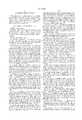
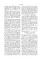
- FIG. 1is a perspective view showing a preferred embodiment of an impact tool for use in surgical procedures of the present invention with a surgical implement coupled thereto;
- FIG. 2is a perspective, exploded view showing the preferred embodiment of the present invention
- FIG. 3is a cross-sectional view of the preferred embodiment showing components thereof;
- FIG. 4is a cross-sectional view of the preferred embodiment showing components thereof in an initial position
- FIGS. 5A and 5Bare a cross-sectional views of a chuck assembly of the preferred embodiment of the present invention.
- FIGS. 6is a cross-sectional view of an extraction embodiment of the present invention.
- the tool 10is preferably fabricated from known light, strong, and rigid biocompatible metal alloys, or polymeric composites, or other known suitable materials.
- the invented tool 10is preferably fabricated from suitable metal alloys, such as a stainless steel alloy sold under the trade name Stellite, and titanium alloys.
- the invented tool 10may also be fabricated from cobalt alloys sold under the trade names Elgiloy and Carpenter MP35.
- the impact tool 10 of the present inventionis useful for performing a number of different functions in various surgical procedures, such as hip replacement procedures.
- Several different surgical implementscan alternately be coupled to the invented tool during surgical procedures, to perform such surgical functions as freeing and removing cement, inserting pins, accurately setting guides, and implanting surgical staples.
- Some of these surgical implementsinclude an acetabular adjuster, a surgical pin inserter, a surgical stapler, a bone chisel, an osteotome, and a gouge.
- the impact tool 10may be utilized in different industrial applications wherever an impact force is desired, such as the several different impact forces associated with construction, for instance.
- the tool 10can be configured into several different dimensions that render the tool 10 suitable for delivering an impact of sufficient force to various fasteners, such as nails or other similar fasteners, to drive the fastener into a surface comprising wood, sheetrock or drywall, or metal alloy surfaces, among others.
- the tool 10 of the present inventionincludes means for effecting removal of various surgical aids and other devices, along with various industrial fasteners. As with installing surgical aids and industrial fasteners, along with other devices, it is often difficult to remove these devices, particularly in a controlled and efficient manner.
- the impact tool 10 of the present inventionis capable of applying an instantaneous extraction force to an object to effect removal of the object from a surface in which at least a portion of the object is imbedded.
- the invented impact tool 10is coupleable to different implements adapted to be secured to a surgical aid, such as a pin.
- the tool 10then is actuated for applying an instantaneous extraction force to the pin, to effect removal of the pin from a bone in which at east a portion of the pin is imbedded.
- the tool 10can be repeatedly actuated until the pin is entirely removed from the bone.
- the invented impact tool 10can be secured to industrial fasteners for removing the fasteners from a surface that the fasteners are imbedded.
- the invented tool 10comprises a handle portion or body 12 having an impact force calibrating means 13 coupled to a first end 16 thereof and a quick disconnect assembly 18 secured in a second end 20.
- the body 12optionally may be provided with an ovular depression 19 formed in the periphery thereof, preferably proximal to the second end 20.
- the depression 19is provided for placement of the user's thumb to enhance grasping of the body 12, for preventing the tool 10 from inadvertently moving in a user's hand while the tool 10 is in use. Additionally, the depression 19 enables a user to determine and maintain a desired orientation of various implements coupled to the quick disconnect assembly 18, when the implement is obscured from the user's view.
- the body 12is elongated and has a channel 24 that extends therethrough and parallel to a longitudinal axis L of the body 12.
- the channel 24has a first region 26 of a first diameter extending from the first end 16 to a midpoint 28 that is intermediate the first and second ends 16, 20, a second region 30 having a diameter greater than the first region 26 extending from the second end 20 to the midpoint 28, and a conical ramp 32 formed about the midpoint 28.
- the conical ramp 32provides a smooth transition region between the first and second regions 26, 30 of the channel 24.
- a portion 34 of the first region 26 of the channel 24may be threaded for receiving the calibrating means 13, and a portion 36 of the second region 30 of the channel 24 may be threaded for coupling the quick disconnect assembly 18 to the body 12.
- the calibrating means 13preferably comprises a conical knob 14 having a screw 38 made integral therewith.
- the screw 38is configured to mate with the threaded portion 34 of the channel's first region 26 for adjustably coupling the knob 14 to the body 12.
- the knob 14may be provided with a multiplicity of spatially positioned elongated furrows 40 formed in the periphery thereof. The furrows 40 are provided to enhance gripping of the knob 14, when adjusting the knob 14 to calibrate and adjust the impact force to be delivered by the tool 10.
- the preferred embodiment of the invented tool 10includes an impact inducing assembly, shown generally at 41, retained in the channel 24.
- the impact inducing assembly 41is provided to cause a surgical implement 42 retained in the quick disconnect assembly 18 to deliver an impact to a desired object, with an impact force calibrated by the calibrating means 13.
- the impact inducing assembly 41comprises a hollow piston 44 slidably retained in the channel 24.
- the piston 44has a head 46 formed on a first end 48, and an elongated cavity 50 disposed through a second end 52 thereof.
- the head 46 of the piston 44has a diameter less than the piston 44, to form a flange 54 about the first end 48.
- a hole 56is formed through a wall 58 of the piston 44 proximal to the second end 52.
- the hole 56extends perpendicular to the cavity 50 and into an inner surface 60 thereof, such that a depression 62 is formed in the inner surface 60 of the piston 44, aligned with the hole 56.
- the impact inducing assembly 41further includes a main spring 64 that is interposed between the piston 44 and calibrating means 13.
- the main spring 64is configured to frictionally, engage the head 46 of the piston 44 and to couple to the screw 38 of the knob 14. In use, as the knob 14 is rotated clockwise, the screw 38 extends further into the first region 26 of the channel 24 to increasingly bias the main spring 64 against the head 46, for increasing the impact force generated by the impact inducing assembly 41.
- the quick disconnect assembly 18includes a chuck 21 having a rod 66 configured to extend into the channel 24, for coupling the quick disconnect assembly 18 to the body 12.
- the rod 66has an end section 68 that extends from an end 70 thereof to a mid section 72.
- the end section 68is dimensioned to extend into the cavity 50, with the mid section 72 having a diameter greater than the diameter of the end section 68, for forming a shoulder 74 about the juncture of the end and mid sections 68, 72.
- each of the end and mid sections 68, 72are substantially cylindrical with chordal sides to prevent the rod 66 from rotating about the longitudinal axis L of the body, when the rod 66 is traveling along the second region 30 of the channel 24 (discussed hereafter).
- a boss 71is formed on the end 70 of the rod 66 to form a flange 73.
- the quick disconnect assembly 18is provided with a quick-release jaw means 22 for quickly attaching and detaching different desired implements, such as the above discussed surgical and industrial implements, to the tool 10.
- the quick-release jaw means 22is integrally formed with the chuck 21 and diametrically opposed to the rod 66.
- the jaw means 22includes a cylindrical mouth 76 that provides access to an elongated opening 78 in the quick disconnect assembly 18.
- the opening 78is configured to receive a connecting portion 80 of an end region 82 of the implement 42 for coupling the implement 42 to the assembly 18.
- the connecting portion 80 of the implement 42comprises a narrowed portion 84 extending between an anterior shoulder 86 and a posterior shoulder 88.
- An end 91 of the connecting portion 80may be configured with chamfered edges 93 so that the implement 42 can be coupled to the quick disconnect assembly 18 without having to depress a push-button 92 thereof (discussed hereinafter).
- any one of several different surgical and industrial implementscan alternately be coupled to the quick disconnect assembly 18, providing that they are configured with an appropriate connecting portion, or other suitable means, for coupling the desired implement to the tool 10.
- Such appropriate implementsinclude an acetabular adjuster, a surgical pin inserter, a surgical stapler, a bone chisel, an osteotome, and a gouge, for example.
- the improved impact tool 10 of the present inventionmay be utilized in different industrial applications wherever an impact force is desired, such as the several different impact forces associated with construction, for instance.
- the impact tool 10can be configured into several different dimensions, along with the components of the tool 10 that produce the impact force.
- the tool 10 37can be dimensioned for delivering substantially large impacts of sufficient force to various fasteners, such as nails or other similar fasteners, to drive the fastener into relatively hard surfaces comprising wood, sheetrock or drywall, or metal alloy surfaces among others, or a somewhat slight impact force for driving small fasteners into relatively soft surfaces.
- the calibrating means 13is provided to enable various dimensioned tools 10 to deliver a substantially wide range of impact forces.
- An aperture 90is disposed through the chuck 21, diametrically opposed to the opening 78 and has the push-button 92 housed therein.
- the push-button 92is configured with an orifice 94 to engage the connecting portion 80 of the implement 42, to releasably couple the implement 42 to the tool 10 of the present invention.
- a small bias spring 96is secured in the aperture 90 for biasing the push-button 92 outwardly. In use, the push-button 92 is depressed to compress the bias spring 96, for aligning the orifice 94 in the button 92 with the opening 78 in the chuck 18, to allow the connecting portion 80 to pass into the opening 78 and through the orifice 94.
- the chamfered edges 93 of the end 91 of the connecting portion 80cause the end 91 to self-align in the aperture 90, as the implement 42 is being coupled to the assembly 18, and to compress the bias spring 96 for coupling the implement 42 to the quick disconnect assembly 18, without having to depress a push-button 92.
- the push-button 92is released by the user or self-releases once the posterior shoulder 88 is beyond the push button 92.
- the spring 96biases the button 92 outwardly for engaging the connecting portion 80, to couple the implement 42 to the chuck 21, and thus to the quick disconnect assembly 18.
- a set screw 98 or other suitable meanscan be disposed through the chuck 21 and adjusted to abut the push-button 92, to prevent the button 92 from inadvertently disengaging the implement 42.
- the impact inducing assembly 41further includes an actuation mechanism, shown generally at 100 in FIG. 2, configured to releasably engage the end section 68 of the rod 66.
- the actuation mechanism 100comprises an actuation spring 102 secured in the depression 62 and a trigger member 104 slidably retained in the hole 56 and coupled to the actuation spring 102.
- the trigger 104has an opening 106 disposed therethrough, perpendicular to the cavity 50 to form a bottom edge 108.
- the opening 106is dimensioned to allow the end section 68 of the rod 66 to extend through the trigger 104 and into the cavity 50.
- the actuation spring 102is provided to bias the trigger 104 outwardly, such that a head 110 thereof normally projects outwardly from the periphery of the piston 44 to contact the transition region 32 of the channel 24.
- a trigger meansmay be disposed through the body 12 and coupled thereto, for actuating the actuation mechanism 100.
- the trigger meansmay be positioned on the periphery of the body 12, between the second end 20 and midpoint 28, depending upon such factors as the intended application of the present invention 10.
- a trigger button 101may be positioned in ovular depression 19, for example, or other suitable locations along the body 12. The trigger button 101 enables the implement 42 to deliver an impact, without the user having to exert substantial pressure on the object, to initiate the impact.
- the trigger button 101enables the tool 10 to be used in applications where only a slight impact force is desired, such as dentistry.
- an antirotation assemblyshown generally at 112 (in FIG. 2), is provided to prevent the implement 42 from rotating relative to the longitudinal axis L, while the rod 66 travels along the second region 30 of the channel 24.
- the antirotation assembly 112includes an adjustable member 114 that is threaded into the threaded portion 36 of the second region 30.
- the adjustable member 114has an aperture 116 disposed therethrough configured complementary to the end and mid sections 68, 72 of the rod 66.
- the aperture 116 disposed through the member 114is annular with chordal sides for allowing the end and mid sections 68, 72 to pass through the aperture 116, and to provide a slip-fit between the mid section 72 and the adjustable member 114.
- a locking nut 118may further be provided to prevent the adjustable member 114 from inadvertently moving along the threaded portion 36 of the channel's second region 30.
- the antirotation assembly 112 and depression 19coact to enable a user to determine and maintain a desired orientation of various implements 42 coupled to the quick disconnect assembly 18, when the implement 42 is obscured from the user's view.
- Return meansare included for causing the rod's end section 68 to be engaged by the actuation mechanism 100 for returning the impact inducing assembly 41 to an initial position (as shown in FIG. 3).
- the return meanscomprises a return spring 120 interposed between the adjustable member 114 and the second end 20 of the body 12 and disposed about the rod's mid section 72.
- a circlip 122is retained in a groove 124 in the rod 66, formed about the juncture of the mid section 72 and a base section 126 of the rod 66.
- the circlip 122 and locking nut 118cooperate to retain the return spring 120 in the second region 30.
- an end cap 128is threadably coupled to the second end 20 of the body 12.
- the end cap 128has an annular opening 130 dimensioned to slip-fit the base section 126, while retaining the circlip 122 in the body 12.
- the return spring 120presses against the nut 118 and circlip 122, to bias the rod 66 toward the second end 20, causing the boss 71 to be engaged by the actuation mechanism 100.
- the impact inducing assembly 41is in an initial position, wherein the main spring 64 exerts force on the piston 44 to retain the actuation mechanism 100 in the second region 30 of the channel 24, for preventing the impact inducing assembly 41 from causing the implement 42 to deliver an impact.
- the piston 44is urged toward the first region 26 of the channel 24, thus compressing the main spring 64.
- the piston 44is urged into the first region 26 until the head 110 of the trigger 104 contacts the transition region 32 of the channel 24.
- the trigger 104is pushed into the hole 56 and compresses the actuation spring 102.
- the trigger 104is pushed into the hole 56 until the bottom edge 108 thereof is flush with the inner surface 60 of the piston 44. This causes the boss 71 and flange 73 to be disengaged by the trigger's bottom edge 108, thus releasing the end section 68 of the rod 66, to allow the end section 68 to pass into the cavity 50.
- the main spring 64instantaneously propels the piston 44 along the end section 68, until the piston's second end 52 strikes the rod's shoulder 74.
- the main spring 64then instantaneously propels the piston 44 and rod 66 outwardly along the channel 24, until the implement 42 impacts the desired object (not shown) with an impact force calibrated by the calibrating means 13.
- the antirotation assembly 112prevents the rod 66 from rotating relative to the body's longitudinal axis L.
- the piston 44is drawn toward the body's first end 16 by the recoil of the main spring 64, since the spring 64 is coupled to the calibrating means 13.
- the return spring 120retains the base section 126 of the rod 66 proximal to the body's second end 20, for withdrawing the end section 68 out of the cavity 50.
- the end section 68is drawn out of the cavity 50, until the boss 71 passes into the opening 106 in the trigger 104.
- the actuation spring 102biases the trigger 104 outwardly, such that the bottom edge 108 engages the boss 71. This enables the tool 10 of the present invention to cause the implement 42 to deliver subsequent impacts to the object with an impact force determined by the calibrating means 13.
- the orientation of the components of the invented impact tool 10 that produce an impactcan essentially be inverted so that the tool 10 can be actuated to apply an instantaneous extraction force to the desired industrial fastener, surgical aid, etc.
- the orientation of the components comprising the impact inducing assembly 41, along with the orientation of the transition region 32 of the channel 24,can essentially be inverted so that invented tool 10 can be actuated to apply an instantaneous extraction force to the desired fastener, surgical aid, or other piece.
- the configuration of the rod 66 and piston 44, along with other desired components of the tool 10may be modified, or other suitable means may be implemented, for securing the rod 66 to a desired component, such as the piston 44, of the impact inducing assembly 41.
- the assembly 41instantaneously draws the quick disconnect assembly's rod 66 into the channel 24 for applying an instantaneous extraction force to the desired object.
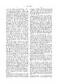
- FIG. 6a possible embodiment of the extraction version 150 is shown.
- the usercalibrates the force to be applied to the object being removed by adjusting the calibration knob 158, thereby adjusting the amount of compression preapplied to the spring 162 of the impact inducing assembly 160.
- One end of the spring 162is located against the end 166 of a collar 164, and the second end of the spring 162 is located against the shoulder 168 of the calibration knob 158.
- the collar 164is located around a rod 170 having an attachment mechanism (not shown) coupled to one end by a quick disconnect assembly 186.
- the userengages the grasping implement, such as a vice or clamp, to the object to be drawn from the surface, then pulls the body 172 away from the object, thereby priming the impact inducing assembly 160.
- the trigger 174is urged towards and eventually contacts the transition region 176 of the channel 152.
- the opening 178 within the trigger 174aligns with the rod 170, thereby releasing the collar 164.
- the spring 162 of the impact inducing assembly 160is released and moves the collar 164 back toward its original position, thereby causing the end of the collar 164 to strike the head 180 of the rod 170.
- the quick disconnect assemblyis provided for alternately quickly attaching and detaching different desired surgical and industrial implements to the tool.
- the orientation of the components of the impact inducing assemblycan be inverted so that the tool is actuated to apply an instantaneous extraction force to the object.
- the antirotation assembly and depressioncoact to enable a user to determine and maintain a desired orientation of various implements coupled to the quick disconnect assembly, when the implement is obscured from the user's view.
Landscapes
- Health & Medical Sciences (AREA)
- Surgery (AREA)
- Life Sciences & Earth Sciences (AREA)
- Orthopedic Medicine & Surgery (AREA)
- Biomedical Technology (AREA)
- Nuclear Medicine, Radiotherapy & Molecular Imaging (AREA)
- Engineering & Computer Science (AREA)
- Heart & Thoracic Surgery (AREA)
- Medical Informatics (AREA)
- Molecular Biology (AREA)
- Animal Behavior & Ethology (AREA)
- General Health & Medical Sciences (AREA)
- Public Health (AREA)
- Veterinary Medicine (AREA)
- Oral & Maxillofacial Surgery (AREA)
- Dentistry (AREA)
- Surgical Instruments (AREA)
Abstract
Description
Claims (18)
Priority Applications (1)
| Application Number | Priority Date | Filing Date | Title |
|---|---|---|---|
| US09/181,387US6010508A (en) | 1996-10-25 | 1998-10-27 | Automatic impact device |
Applications Claiming Priority (3)
| Application Number | Priority Date | Filing Date | Title |
|---|---|---|---|
| US08/735,185US5735855A (en) | 1996-10-25 | 1996-10-25 | Automatic impact device |
| US08/958,773US5827290A (en) | 1996-10-25 | 1997-10-27 | Automatic impact device |
| US09/181,387US6010508A (en) | 1996-10-25 | 1998-10-27 | Automatic impact device |
Related Parent Applications (1)
| Application Number | Title | Priority Date | Filing Date |
|---|---|---|---|
| US08/958,773Continuation-In-PartUS5827290A (en) | 1996-10-25 | 1997-10-27 | Automatic impact device |
Publications (1)
| Publication Number | Publication Date |
|---|---|
| US6010508Atrue US6010508A (en) | 2000-01-04 |
Family
ID=27112853
Family Applications (1)
| Application Number | Title | Priority Date | Filing Date |
|---|---|---|---|
| US09/181,387Expired - LifetimeUS6010508A (en) | 1996-10-25 | 1998-10-27 | Automatic impact device |
Country Status (1)
| Country | Link |
|---|---|
| US (1) | US6010508A (en) |
Cited By (56)
| Publication number | Priority date | Publication date | Assignee | Title |
|---|---|---|---|---|
| US6139165A (en)* | 1999-04-30 | 2000-10-31 | Crowe; Robert E. | Combination flashlight or nightstick/baton rescue punch assembly |
| GB2372707A (en)* | 2001-01-05 | 2002-09-04 | Derek James Wallace Mcminn | An instrument and femoral implant for use in hip resurfacing |
| US20030032966A1 (en)* | 1999-10-20 | 2003-02-13 | Foley Kevin T. | Methods and instrumentation for distraction of a disc space |
| US6520966B1 (en)* | 1999-09-21 | 2003-02-18 | Sulzer Orthopedics Ltd. | Setting instrument for a tibia part of a knee joint prosthesis |
| US20040064145A1 (en)* | 2002-09-30 | 2004-04-01 | Ball Robert J. | Force specific impacting device |
| USD492775S1 (en) | 2003-02-12 | 2004-07-06 | Kyphon Inc. | Impact handle for hand held surgical instruments |
| EP1486176A1 (en)* | 2003-06-11 | 2004-12-15 | Stryker Trauma GmbH | Combination of an intramedullary pin and a targering device or/and a percussion device |
| US7004946B2 (en) | 2002-10-30 | 2006-02-28 | Symmetry Medical, Inc. | Acetabular cup impactor |
| US20070123889A1 (en)* | 2005-10-14 | 2007-05-31 | Malandain Hugues F | Mechanical cavity-creation surgical device and methods and kits for using such devices |
| US20070156155A1 (en)* | 2006-01-03 | 2007-07-05 | Parker Brad A | Surgical cup impactor |
| US20080154268A1 (en)* | 2006-12-20 | 2008-06-26 | Howmedica Osteonics Corp. | Femoral cutting block |
| US20090299416A1 (en)* | 2005-10-10 | 2009-12-03 | Haenni Markus | Aiming Device |
| US20100114174A1 (en)* | 2008-10-30 | 2010-05-06 | Bryan Jones | Systems and Methods for Delivering Bone Cement to a Bone Anchor |
| US20100331851A1 (en)* | 2009-06-24 | 2010-12-30 | Huene Donald | Surgical slap hammer |
| US20110028979A1 (en)* | 2009-07-31 | 2011-02-03 | Warsaw Orthopedic, Inc. | Spinal Implant Clearing Gouge |
| US20120024117A1 (en)* | 2010-07-29 | 2012-02-02 | Kreutzer Robert E | Starter Tool |
| US20120285714A1 (en)* | 2011-05-11 | 2012-11-15 | Dynamatic Solutions, Llc | Impact tool assembly and method of assembling same |
| US8603102B2 (en) | 2009-05-26 | 2013-12-10 | Zimmer, Inc. | Bone fixation tool |
| US20140060269A1 (en)* | 2012-08-29 | 2014-03-06 | Jack Lin | Impact Driver |
| CN104161583A (en)* | 2014-08-18 | 2014-11-26 | 东莞乐域光电科技有限公司 | Medical torsion tool with counting and self-destruction functions |
| US9155580B2 (en) | 2011-08-25 | 2015-10-13 | Medos International Sarl | Multi-threaded cannulated bone anchors |
| US9283020B2 (en) | 2011-01-03 | 2016-03-15 | Warsaw Orthopedic, Inc. | Surgical tack delivery system, method and kit |
| USD780548S1 (en) | 2015-07-22 | 2017-03-07 | Ac (Macao Commercial Offshore) Limited | Power tool |
| WO2017186490A1 (en)* | 2016-04-27 | 2017-11-02 | Depuy Ireland Unlimited Company | An impactor |
| USD806493S1 (en) | 2015-07-22 | 2018-01-02 | Tti (Macao Commercial Offshore) Limited | Tool adapter |
| US9987067B2 (en) | 2012-07-11 | 2018-06-05 | Zimmer, Inc. | Bone fixation tool |
| US20180161171A1 (en)* | 2016-12-14 | 2018-06-14 | DePuy Synthes Products, Inc. | Intervertebral implant inserter and related methods |
| US20180289377A1 (en)* | 2017-04-06 | 2018-10-11 | Emory Clark | Hand-held spring tool |
| US10179017B2 (en) | 2014-04-03 | 2019-01-15 | Zimmer, Inc. | Orthopedic tool for bone fixation |
| KR20200136201A (en)* | 2019-05-27 | 2020-12-07 | 주식회사 덴티움 | Impactor for practicing medical operation |
| US10940016B2 (en) | 2017-07-05 | 2021-03-09 | Medos International Sarl | Expandable intervertebral fusion cage |
| US10966840B2 (en) | 2010-06-24 | 2021-04-06 | DePuy Synthes Products, Inc. | Enhanced cage insertion assembly |
| US10973652B2 (en) | 2007-06-26 | 2021-04-13 | DePuy Synthes Products, Inc. | Highly lordosed fusion cage |
| EP3888579A1 (en)* | 2020-03-30 | 2021-10-06 | Shukla Medical | Handle assembly for a surgical tool |
| US11273050B2 (en) | 2006-12-07 | 2022-03-15 | DePuy Synthes Products, Inc. | Intervertebral implant |
| US11344424B2 (en) | 2017-06-14 | 2022-05-31 | Medos International Sarl | Expandable intervertebral implant and related methods |
| US11426290B2 (en) | 2015-03-06 | 2022-08-30 | DePuy Synthes Products, Inc. | Expandable intervertebral implant, system, kit and method |
| US11426286B2 (en) | 2020-03-06 | 2022-08-30 | Eit Emerging Implant Technologies Gmbh | Expandable intervertebral implant |
| US11446156B2 (en) | 2018-10-25 | 2022-09-20 | Medos International Sarl | Expandable intervertebral implant, inserter instrument, and related methods |
| US11446155B2 (en) | 2017-05-08 | 2022-09-20 | Medos International Sarl | Expandable cage |
| US11452607B2 (en) | 2010-10-11 | 2022-09-27 | DePuy Synthes Products, Inc. | Expandable interspinous process spacer implant |
| US11497619B2 (en) | 2013-03-07 | 2022-11-15 | DePuy Synthes Products, Inc. | Intervertebral implant |
| US11510788B2 (en) | 2016-06-28 | 2022-11-29 | Eit Emerging Implant Technologies Gmbh | Expandable, angularly adjustable intervertebral cages |
| US11596522B2 (en) | 2016-06-28 | 2023-03-07 | Eit Emerging Implant Technologies Gmbh | Expandable and angularly adjustable intervertebral cages with articulating joint |
| US11602438B2 (en) | 2008-04-05 | 2023-03-14 | DePuy Synthes Products, Inc. | Expandable intervertebral implant |
| US11607321B2 (en) | 2009-12-10 | 2023-03-21 | DePuy Synthes Products, Inc. | Bellows-like expandable interbody fusion cage |
| US11612491B2 (en) | 2009-03-30 | 2023-03-28 | DePuy Synthes Products, Inc. | Zero profile spinal fusion cage |
| US11654033B2 (en) | 2010-06-29 | 2023-05-23 | DePuy Synthes Products, Inc. | Distractible intervertebral implant |
| US11737881B2 (en) | 2008-01-17 | 2023-08-29 | DePuy Synthes Products, Inc. | Expandable intervertebral implant and associated method of manufacturing the same |
| US11752009B2 (en) | 2021-04-06 | 2023-09-12 | Medos International Sarl | Expandable intervertebral fusion cage |
| US11850160B2 (en) | 2021-03-26 | 2023-12-26 | Medos International Sarl | Expandable lordotic intervertebral fusion cage |
| US20240032978A1 (en)* | 2022-07-28 | 2024-02-01 | Aesculap Ag | Medical impact instrument |
| US11911287B2 (en) | 2010-06-24 | 2024-02-27 | DePuy Synthes Products, Inc. | Lateral spondylolisthesis reduction cage |
| USRE49973E1 (en) | 2013-02-28 | 2024-05-21 | DePuy Synthes Products, Inc. | Expandable intervertebral implant, system, kit and method |
| US12090064B2 (en) | 2022-03-01 | 2024-09-17 | Medos International Sarl | Stabilization members for expandable intervertebral implants, and related systems and methods |
| US12440346B2 (en) | 2023-03-31 | 2025-10-14 | DePuy Synthes Products, Inc. | Expandable intervertebral implant |
Citations (2)
| Publication number | Priority date | Publication date | Assignee | Title |
|---|---|---|---|---|
| US5490683A (en)* | 1994-07-27 | 1996-02-13 | Mednext Inc. | Tool shaft coupler |
| US5569256A (en)* | 1995-02-10 | 1996-10-29 | Midas Rex Pneumatic Tools, Inc. | Surgical resection tool with a double quick release |
- 1998
- 1998-10-27USUS09/181,387patent/US6010508A/ennot_activeExpired - Lifetime
Patent Citations (2)
| Publication number | Priority date | Publication date | Assignee | Title |
|---|---|---|---|---|
| US5490683A (en)* | 1994-07-27 | 1996-02-13 | Mednext Inc. | Tool shaft coupler |
| US5569256A (en)* | 1995-02-10 | 1996-10-29 | Midas Rex Pneumatic Tools, Inc. | Surgical resection tool with a double quick release |
Cited By (112)
| Publication number | Priority date | Publication date | Assignee | Title |
|---|---|---|---|---|
| US6139165A (en)* | 1999-04-30 | 2000-10-31 | Crowe; Robert E. | Combination flashlight or nightstick/baton rescue punch assembly |
| US6520966B1 (en)* | 1999-09-21 | 2003-02-18 | Sulzer Orthopedics Ltd. | Setting instrument for a tibia part of a knee joint prosthesis |
| US20030032966A1 (en)* | 1999-10-20 | 2003-02-13 | Foley Kevin T. | Methods and instrumentation for distraction of a disc space |
| US8100917B2 (en) | 1999-10-20 | 2012-01-24 | Warsaw Orthopedic, Inc. | Methods and instrumentation for distraction of a disc space |
| US20100241127A1 (en)* | 1999-10-20 | 2010-09-23 | Foley Kevin T | Methods and instrumentation for distraction of a disc space |
| US7648512B2 (en) | 1999-10-20 | 2010-01-19 | Warsaw Orthopedic, Inc. | Methods and instrumentation for distraction of a disc space |
| US6855148B2 (en)* | 1999-10-20 | 2005-02-15 | Sdgi Holdings, Inc. | Methods and instrumentation for distraction of a disc space |
| US20050154396A1 (en)* | 1999-10-20 | 2005-07-14 | Foley Kevin T. | Methods and instrumentation for distraction of a disc space |
| GB2372707A (en)* | 2001-01-05 | 2002-09-04 | Derek James Wallace Mcminn | An instrument and femoral implant for use in hip resurfacing |
| US20040064145A1 (en)* | 2002-09-30 | 2004-04-01 | Ball Robert J. | Force specific impacting device |
| US7172598B2 (en) | 2002-09-30 | 2007-02-06 | Depuy Products, Inc. | Force specific impacting device |
| US7004946B2 (en) | 2002-10-30 | 2006-02-28 | Symmetry Medical, Inc. | Acetabular cup impactor |
| USD492775S1 (en) | 2003-02-12 | 2004-07-06 | Kyphon Inc. | Impact handle for hand held surgical instruments |
| US20050004600A1 (en)* | 2003-06-11 | 2005-01-06 | Stryker Trauma Gmbh | Coupling system for an intramedullary nail and associated instruments |
| US8337505B2 (en) | 2003-06-11 | 2012-12-25 | Stryker Trauma Gmbh | Method for coupling an intramedullary nail and associated instruments |
| EP1486176A1 (en)* | 2003-06-11 | 2004-12-15 | Stryker Trauma GmbH | Combination of an intramedullary pin and a targering device or/and a percussion device |
| US20110078887A1 (en)* | 2003-06-11 | 2011-04-07 | Stryker Trauma Gmbh | Method for coupling an intramedullary nail and associated instruments |
| US7901410B2 (en) | 2003-06-11 | 2011-03-08 | Stryker Trauma Gmbh | Coupling system for an intramedullary nail and associated instruments |
| US9687258B2 (en) | 2005-10-10 | 2017-06-27 | DePuy Synthes Products, Inc. | Aiming device |
| US9888930B2 (en) | 2005-10-10 | 2018-02-13 | DePuy Synthes Products, Inc. | Aiming device |
| US20090299416A1 (en)* | 2005-10-10 | 2009-12-03 | Haenni Markus | Aiming Device |
| CN101282690B (en)* | 2005-10-10 | 2011-05-18 | 斯恩蒂斯有限公司 | Aiming device |
| US20070123889A1 (en)* | 2005-10-14 | 2007-05-31 | Malandain Hugues F | Mechanical cavity-creation surgical device and methods and kits for using such devices |
| US20070156155A1 (en)* | 2006-01-03 | 2007-07-05 | Parker Brad A | Surgical cup impactor |
| US11660206B2 (en) | 2006-12-07 | 2023-05-30 | DePuy Synthes Products, Inc. | Intervertebral implant |
| US11273050B2 (en) | 2006-12-07 | 2022-03-15 | DePuy Synthes Products, Inc. | Intervertebral implant |
| US11432942B2 (en) | 2006-12-07 | 2022-09-06 | DePuy Synthes Products, Inc. | Intervertebral implant |
| US11497618B2 (en) | 2006-12-07 | 2022-11-15 | DePuy Synthes Products, Inc. | Intervertebral implant |
| US11712345B2 (en) | 2006-12-07 | 2023-08-01 | DePuy Synthes Products, Inc. | Intervertebral implant |
| US11642229B2 (en) | 2006-12-07 | 2023-05-09 | DePuy Synthes Products, Inc. | Intervertebral implant |
| US20080154268A1 (en)* | 2006-12-20 | 2008-06-26 | Howmedica Osteonics Corp. | Femoral cutting block |
| US8821500B2 (en)* | 2006-12-20 | 2014-09-02 | Howmedica Osteonics Corp. | Femoral cutting block |
| US10973652B2 (en) | 2007-06-26 | 2021-04-13 | DePuy Synthes Products, Inc. | Highly lordosed fusion cage |
| US11622868B2 (en) | 2007-06-26 | 2023-04-11 | DePuy Synthes Products, Inc. | Highly lordosed fusion cage |
| US11737881B2 (en) | 2008-01-17 | 2023-08-29 | DePuy Synthes Products, Inc. | Expandable intervertebral implant and associated method of manufacturing the same |
| US11701234B2 (en) | 2008-04-05 | 2023-07-18 | DePuy Synthes Products, Inc. | Expandable intervertebral implant |
| US11602438B2 (en) | 2008-04-05 | 2023-03-14 | DePuy Synthes Products, Inc. | Expandable intervertebral implant |
| US12023255B2 (en) | 2008-04-05 | 2024-07-02 | DePuy Synthes Products, Inc. | Expandable inter vertebral implant |
| US11707359B2 (en) | 2008-04-05 | 2023-07-25 | DePuy Synthes Products, Inc. | Expandable intervertebral implant |
| US11712341B2 (en) | 2008-04-05 | 2023-08-01 | DePuy Synthes Products, Inc. | Expandable intervertebral implant |
| US11712342B2 (en) | 2008-04-05 | 2023-08-01 | DePuy Synthes Products, Inc. | Expandable intervertebral implant |
| US11617655B2 (en) | 2008-04-05 | 2023-04-04 | DePuy Synthes Products, Inc. | Expandable intervertebral implant |
| US12011361B2 (en) | 2008-04-05 | 2024-06-18 | DePuy Synthes Products, Inc. | Expandable intervertebral implant |
| US20100114174A1 (en)* | 2008-10-30 | 2010-05-06 | Bryan Jones | Systems and Methods for Delivering Bone Cement to a Bone Anchor |
| USRE47871E1 (en) | 2008-10-30 | 2020-02-25 | DePuy Synthes Products, Inc. | Systems and methods for delivering bone cement to a bone anchor |
| US9265548B2 (en) | 2008-10-30 | 2016-02-23 | DePuy Synthes Products, Inc. | Systems and methods for delivering bone cement to a bone anchor |
| USRE48870E1 (en) | 2008-10-30 | 2022-01-04 | DePuy Synthes Products, Inc. | Systems and methods for delivering bone cement to a bone anchor |
| USRE50403E1 (en) | 2008-10-30 | 2025-04-29 | DePuy Synthes Products, Inc. | Systems and methods for delivering bone cement to a bone anchor |
| US12097124B2 (en) | 2009-03-30 | 2024-09-24 | DePuy Synthes Products, Inc. | Zero profile spinal fusion cage |
| US11612491B2 (en) | 2009-03-30 | 2023-03-28 | DePuy Synthes Products, Inc. | Zero profile spinal fusion cage |
| US8603102B2 (en) | 2009-05-26 | 2013-12-10 | Zimmer, Inc. | Bone fixation tool |
| US8852202B2 (en) | 2009-05-26 | 2014-10-07 | Zimmer, Inc. | Bone fixation tool |
| US20100331851A1 (en)* | 2009-06-24 | 2010-12-30 | Huene Donald | Surgical slap hammer |
| US8486084B2 (en) | 2009-06-24 | 2013-07-16 | Donald HUENE | Surgical slap hammer |
| US20110028979A1 (en)* | 2009-07-31 | 2011-02-03 | Warsaw Orthopedic, Inc. | Spinal Implant Clearing Gouge |
| US11607321B2 (en) | 2009-12-10 | 2023-03-21 | DePuy Synthes Products, Inc. | Bellows-like expandable interbody fusion cage |
| US11911287B2 (en) | 2010-06-24 | 2024-02-27 | DePuy Synthes Products, Inc. | Lateral spondylolisthesis reduction cage |
| US12318304B2 (en) | 2010-06-24 | 2025-06-03 | DePuy Synthes Products, Inc. | Lateral spondylolisthesis reduction cage |
| US10966840B2 (en) | 2010-06-24 | 2021-04-06 | DePuy Synthes Products, Inc. | Enhanced cage insertion assembly |
| US11872139B2 (en) | 2010-06-24 | 2024-01-16 | DePuy Synthes Products, Inc. | Enhanced cage insertion assembly |
| US11654033B2 (en) | 2010-06-29 | 2023-05-23 | DePuy Synthes Products, Inc. | Distractible intervertebral implant |
| US20120024117A1 (en)* | 2010-07-29 | 2012-02-02 | Kreutzer Robert E | Starter Tool |
| US11452607B2 (en) | 2010-10-11 | 2022-09-27 | DePuy Synthes Products, Inc. | Expandable interspinous process spacer implant |
| US9888952B2 (en) | 2011-01-03 | 2018-02-13 | Warsaw Orthopedic, Inc | Surgical tack delivery system, method and kit |
| US9283020B2 (en) | 2011-01-03 | 2016-03-15 | Warsaw Orthopedic, Inc. | Surgical tack delivery system, method and kit |
| US20120285714A1 (en)* | 2011-05-11 | 2012-11-15 | Dynamatic Solutions, Llc | Impact tool assembly and method of assembling same |
| US9206577B2 (en)* | 2011-05-11 | 2015-12-08 | Dynamatic Solutions, Llc | Impact tool assembly and method of assembling same |
| US9155580B2 (en) | 2011-08-25 | 2015-10-13 | Medos International Sarl | Multi-threaded cannulated bone anchors |
| US11202659B2 (en) | 2011-08-25 | 2021-12-21 | Medos International Sarl | Bone anchors |
| US12185999B2 (en) | 2011-08-25 | 2025-01-07 | Medos International Sàrl | Bone anchors |
| US10321937B2 (en) | 2011-08-25 | 2019-06-18 | Medos International Sarl | Bone anchors |
| US9987067B2 (en) | 2012-07-11 | 2018-06-05 | Zimmer, Inc. | Bone fixation tool |
| US20140060269A1 (en)* | 2012-08-29 | 2014-03-06 | Jack Lin | Impact Driver |
| US8844409B2 (en)* | 2012-08-29 | 2014-09-30 | Yih Cheng Factory Co., Ltd. | Impact driver |
| USRE49973E1 (en) | 2013-02-28 | 2024-05-21 | DePuy Synthes Products, Inc. | Expandable intervertebral implant, system, kit and method |
| US11497619B2 (en) | 2013-03-07 | 2022-11-15 | DePuy Synthes Products, Inc. | Intervertebral implant |
| US11850164B2 (en) | 2013-03-07 | 2023-12-26 | DePuy Synthes Products, Inc. | Intervertebral implant |
| US10179017B2 (en) | 2014-04-03 | 2019-01-15 | Zimmer, Inc. | Orthopedic tool for bone fixation |
| CN104161583A (en)* | 2014-08-18 | 2014-11-26 | 东莞乐域光电科技有限公司 | Medical torsion tool with counting and self-destruction functions |
| US11426290B2 (en) | 2015-03-06 | 2022-08-30 | DePuy Synthes Products, Inc. | Expandable intervertebral implant, system, kit and method |
| USD780548S1 (en) | 2015-07-22 | 2017-03-07 | Ac (Macao Commercial Offshore) Limited | Power tool |
| USD806493S1 (en) | 2015-07-22 | 2018-01-02 | Tti (Macao Commercial Offshore) Limited | Tool adapter |
| CN109069277A (en)* | 2016-04-27 | 2018-12-21 | 德普伊爱尔兰无限公司 | impactor |
| US10849765B2 (en) | 2016-04-27 | 2020-12-01 | Depuy Ireland Unlimited Company | Impactor |
| WO2017186490A1 (en)* | 2016-04-27 | 2017-11-02 | Depuy Ireland Unlimited Company | An impactor |
| US11596522B2 (en) | 2016-06-28 | 2023-03-07 | Eit Emerging Implant Technologies Gmbh | Expandable and angularly adjustable intervertebral cages with articulating joint |
| US11510788B2 (en) | 2016-06-28 | 2022-11-29 | Eit Emerging Implant Technologies Gmbh | Expandable, angularly adjustable intervertebral cages |
| US11596523B2 (en) | 2016-06-28 | 2023-03-07 | Eit Emerging Implant Technologies Gmbh | Expandable and angularly adjustable articulating intervertebral cages |
| US12433757B2 (en) | 2016-06-28 | 2025-10-07 | Eit Emerging Implant Technologies Gmbh | Expandable, angularly adjustable and articulating intervertebral cages |
| US12390343B2 (en) | 2016-06-28 | 2025-08-19 | Eit Emerging Implant Technologies Gmbh | Expandable, angularly adjustable intervertebral cages |
| US20180161171A1 (en)* | 2016-12-14 | 2018-06-14 | DePuy Synthes Products, Inc. | Intervertebral implant inserter and related methods |
| US10888433B2 (en)* | 2016-12-14 | 2021-01-12 | DePuy Synthes Products, Inc. | Intervertebral implant inserter and related methods |
| US10524804B2 (en)* | 2017-04-06 | 2020-01-07 | Stryker Tools, LLC. | Hand-held spring tool |
| US20180289377A1 (en)* | 2017-04-06 | 2018-10-11 | Emory Clark | Hand-held spring tool |
| US11446155B2 (en) | 2017-05-08 | 2022-09-20 | Medos International Sarl | Expandable cage |
| US12427031B2 (en) | 2017-05-08 | 2025-09-30 | Medos International Sarl | Expandable cage |
| US11344424B2 (en) | 2017-06-14 | 2022-05-31 | Medos International Sarl | Expandable intervertebral implant and related methods |
| US10940016B2 (en) | 2017-07-05 | 2021-03-09 | Medos International Sarl | Expandable intervertebral fusion cage |
| US11446156B2 (en) | 2018-10-25 | 2022-09-20 | Medos International Sarl | Expandable intervertebral implant, inserter instrument, and related methods |
| KR102254406B1 (en)* | 2019-05-27 | 2021-05-21 | 주식회사 덴티움 | Impactor for practicing medical operation |
| WO2020242100A3 (en)* | 2019-05-27 | 2021-02-04 | 주식회사 덴티움 | Impactor for medical procedure |
| KR20200136201A (en)* | 2019-05-27 | 2020-12-07 | 주식회사 덴티움 | Impactor for practicing medical operation |
| US11806245B2 (en) | 2020-03-06 | 2023-11-07 | Eit Emerging Implant Technologies Gmbh | Expandable intervertebral implant |
| US11426286B2 (en) | 2020-03-06 | 2022-08-30 | Eit Emerging Implant Technologies Gmbh | Expandable intervertebral implant |
| US11440177B2 (en) | 2020-03-30 | 2022-09-13 | Shukla Medical | Handle assembly for a surgical tool |
| EP3888579A1 (en)* | 2020-03-30 | 2021-10-06 | Shukla Medical | Handle assembly for a surgical tool |
| US11850160B2 (en) | 2021-03-26 | 2023-12-26 | Medos International Sarl | Expandable lordotic intervertebral fusion cage |
| US12023258B2 (en) | 2021-04-06 | 2024-07-02 | Medos International Sarl | Expandable intervertebral fusion cage |
| US11752009B2 (en) | 2021-04-06 | 2023-09-12 | Medos International Sarl | Expandable intervertebral fusion cage |
| US12090064B2 (en) | 2022-03-01 | 2024-09-17 | Medos International Sarl | Stabilization members for expandable intervertebral implants, and related systems and methods |
| US20240032978A1 (en)* | 2022-07-28 | 2024-02-01 | Aesculap Ag | Medical impact instrument |
| US12440346B2 (en) | 2023-03-31 | 2025-10-14 | DePuy Synthes Products, Inc. | Expandable intervertebral implant |
Similar Documents
| Publication | Publication Date | Title |
|---|---|---|
| US6010508A (en) | Automatic impact device | |
| US5827290A (en) | Automatic impact device | |
| US7341593B2 (en) | Prosthetic acetabular cup inserter | |
| AU2017210500B2 (en) | Electric motor driven tool for orthopedic impacting | |
| US6679888B2 (en) | Femur lever | |
| EP1707160B1 (en) | Controlled force impacting device | |
| US6565575B2 (en) | Method and apparatus for removing an acetabular cup | |
| US5800440A (en) | Device for inserting a surgical pin | |
| EP3515370B1 (en) | An automated slaphammer to remove orthopaedic implants | |
| US20150011999A1 (en) | Osteosynthesis clip and insertion tool for use with bone tissue fragments | |
| US20100076438A1 (en) | Keel punch impactor with connection device | |
| US7247158B2 (en) | Acetabular impactor | |
| KR20190046710A (en) | Orthopedic device delivering controlled, repeatable impact | |
| JP2018525118A (en) | Surgical tray, instrument, and method for implanting a hip replacement | |
| JP2003509105A (en) | Bone debris reduction device | |
| GB2307861A (en) | Prosthesis holding device | |
| US20240238026A1 (en) | Orthopedic slide hammer instrument | |
| EP0312957A2 (en) | Device for removing cement from the femoral medullary canal particularly in the replacement of hip prostheses | |
| HK1208336B (en) | Electric motor driven tool for orthopedic impacting |
Legal Events
| Date | Code | Title | Description |
|---|---|---|---|
| REMI | Maintenance fee reminder mailed | ||
| REIN | Reinstatement after maintenance fee payment confirmed | ||
| FP | Lapsed due to failure to pay maintenance fee | Effective date:20030104 | |
| FPAY | Fee payment | Year of fee payment:4 | |
| SULP | Surcharge for late payment | ||
| FEPP | Fee payment procedure | Free format text:PETITION RELATED TO MAINTENANCE FEES FILED (ORIGINAL EVENT CODE: PMFP); ENTITY STATUS OF PATENT OWNER: LARGE ENTITY | |
| FEPP | Fee payment procedure | Free format text:PETITION RELATED TO MAINTENANCE FEES GRANTED (ORIGINAL EVENT CODE: PMFG); ENTITY STATUS OF PATENT OWNER: LARGE ENTITY | |
| FPAY | Fee payment | Year of fee payment:8 | |
| SULP | Surcharge for late payment | Year of fee payment:7 | |
| PRDP | Patent reinstated due to the acceptance of a late maintenance fee | Effective date:20080708 | |
| STCF | Information on status: patent grant | Free format text:PATENTED CASE | |
| FEPP | Fee payment procedure | Free format text:PAT HOLDER NO LONGER CLAIMS SMALL ENTITY STATUS, ENTITY STATUS SET TO UNDISCOUNTED (ORIGINAL EVENT CODE: STOL); ENTITY STATUS OF PATENT OWNER: LARGE ENTITY | |
| REFU | Refund | Free format text:REFUND - 7.5 YR SURCHARGE - LATE PMT W/IN 6 MO, SMALL ENTITY (ORIGINAL EVENT CODE: R2555); ENTITY STATUS OF PATENT OWNER: LARGE ENTITY Free format text:REFUND - PAYMENT OF MAINTENANCE FEE, 12TH YR, SMALL ENTITY (ORIGINAL EVENT CODE: R2553); ENTITY STATUS OF PATENT OWNER: LARGE ENTITY Free format text:REFUND - PAYMENT OF MAINTENANCE FEE, 8TH YR, SMALL ENTITY (ORIGINAL EVENT CODE: R2552); ENTITY STATUS OF PATENT OWNER: LARGE ENTITY | |
| FPAY | Fee payment | Year of fee payment:12 |