US6010336A - Living body-supporting member and preparation process thereof - Google Patents
Living body-supporting member and preparation process thereofDownload PDFInfo
- Publication number
- US6010336A US6010336AUS08/580,018US58001895AUS6010336AUS 6010336 AUS6010336 AUS 6010336AUS 58001895 AUS58001895 AUS 58001895AUS 6010336 AUS6010336 AUS 6010336A
- Authority
- US
- United States
- Prior art keywords
- green sheets
- supporting member
- living body
- pores
- preparing
- Prior art date
- Legal status (The legal status is an assumption and is not a legal conclusion. Google has not performed a legal analysis and makes no representation as to the accuracy of the status listed.)
- Expired - Lifetime
Links
Images

Classifications
- A—HUMAN NECESSITIES
- A61—MEDICAL OR VETERINARY SCIENCE; HYGIENE
- A61F—FILTERS IMPLANTABLE INTO BLOOD VESSELS; PROSTHESES; DEVICES PROVIDING PATENCY TO, OR PREVENTING COLLAPSING OF, TUBULAR STRUCTURES OF THE BODY, e.g. STENTS; ORTHOPAEDIC, NURSING OR CONTRACEPTIVE DEVICES; FOMENTATION; TREATMENT OR PROTECTION OF EYES OR EARS; BANDAGES, DRESSINGS OR ABSORBENT PADS; FIRST-AID KITS
- A61F2/00—Filters implantable into blood vessels; Prostheses, i.e. artificial substitutes or replacements for parts of the body; Appliances for connecting them with the body; Devices providing patency to, or preventing collapsing of, tubular structures of the body, e.g. stents
- A61F2/02—Prostheses implantable into the body
- A61F2/28—Bones
- A—HUMAN NECESSITIES
- A61—MEDICAL OR VETERINARY SCIENCE; HYGIENE
- A61F—FILTERS IMPLANTABLE INTO BLOOD VESSELS; PROSTHESES; DEVICES PROVIDING PATENCY TO, OR PREVENTING COLLAPSING OF, TUBULAR STRUCTURES OF THE BODY, e.g. STENTS; ORTHOPAEDIC, NURSING OR CONTRACEPTIVE DEVICES; FOMENTATION; TREATMENT OR PROTECTION OF EYES OR EARS; BANDAGES, DRESSINGS OR ABSORBENT PADS; FIRST-AID KITS
- A61F2/00—Filters implantable into blood vessels; Prostheses, i.e. artificial substitutes or replacements for parts of the body; Appliances for connecting them with the body; Devices providing patency to, or preventing collapsing of, tubular structures of the body, e.g. stents
- A61F2/02—Prostheses implantable into the body
- A61F2/30—Joints
- A61F2/30767—Special external or bone-contacting surface, e.g. coating for improving bone ingrowth
- A—HUMAN NECESSITIES
- A61—MEDICAL OR VETERINARY SCIENCE; HYGIENE
- A61L—METHODS OR APPARATUS FOR STERILISING MATERIALS OR OBJECTS IN GENERAL; DISINFECTION, STERILISATION OR DEODORISATION OF AIR; CHEMICAL ASPECTS OF BANDAGES, DRESSINGS, ABSORBENT PADS OR SURGICAL ARTICLES; MATERIALS FOR BANDAGES, DRESSINGS, ABSORBENT PADS OR SURGICAL ARTICLES
- A61L27/00—Materials for grafts or prostheses or for coating grafts or prostheses
- A61L27/02—Inorganic materials
- A61L27/10—Ceramics or glasses
- A—HUMAN NECESSITIES
- A61—MEDICAL OR VETERINARY SCIENCE; HYGIENE
- A61L—METHODS OR APPARATUS FOR STERILISING MATERIALS OR OBJECTS IN GENERAL; DISINFECTION, STERILISATION OR DEODORISATION OF AIR; CHEMICAL ASPECTS OF BANDAGES, DRESSINGS, ABSORBENT PADS OR SURGICAL ARTICLES; MATERIALS FOR BANDAGES, DRESSINGS, ABSORBENT PADS OR SURGICAL ARTICLES
- A61L27/00—Materials for grafts or prostheses or for coating grafts or prostheses
- A61L27/02—Inorganic materials
- A61L27/12—Phosphorus-containing materials, e.g. apatite
- A—HUMAN NECESSITIES
- A61—MEDICAL OR VETERINARY SCIENCE; HYGIENE
- A61F—FILTERS IMPLANTABLE INTO BLOOD VESSELS; PROSTHESES; DEVICES PROVIDING PATENCY TO, OR PREVENTING COLLAPSING OF, TUBULAR STRUCTURES OF THE BODY, e.g. STENTS; ORTHOPAEDIC, NURSING OR CONTRACEPTIVE DEVICES; FOMENTATION; TREATMENT OR PROTECTION OF EYES OR EARS; BANDAGES, DRESSINGS OR ABSORBENT PADS; FIRST-AID KITS
- A61F2/00—Filters implantable into blood vessels; Prostheses, i.e. artificial substitutes or replacements for parts of the body; Appliances for connecting them with the body; Devices providing patency to, or preventing collapsing of, tubular structures of the body, e.g. stents
- A61F2/02—Prostheses implantable into the body
- A61F2/30—Joints
- A61F2/38—Joints for elbows or knees
- A61F2/3859—Femoral components
- A—HUMAN NECESSITIES
- A61—MEDICAL OR VETERINARY SCIENCE; HYGIENE
- A61F—FILTERS IMPLANTABLE INTO BLOOD VESSELS; PROSTHESES; DEVICES PROVIDING PATENCY TO, OR PREVENTING COLLAPSING OF, TUBULAR STRUCTURES OF THE BODY, e.g. STENTS; ORTHOPAEDIC, NURSING OR CONTRACEPTIVE DEVICES; FOMENTATION; TREATMENT OR PROTECTION OF EYES OR EARS; BANDAGES, DRESSINGS OR ABSORBENT PADS; FIRST-AID KITS
- A61F2/00—Filters implantable into blood vessels; Prostheses, i.e. artificial substitutes or replacements for parts of the body; Appliances for connecting them with the body; Devices providing patency to, or preventing collapsing of, tubular structures of the body, e.g. stents
- A61F2/02—Prostheses implantable into the body
- A61F2/30—Joints
- A61F2002/30001—Additional features of subject-matter classified in A61F2/28, A61F2/30 and subgroups thereof
- A61F2002/30003—Material related properties of the prosthesis or of a coating on the prosthesis
- A61F2002/30004—Material related properties of the prosthesis or of a coating on the prosthesis the prosthesis being made from materials having different values of a given property at different locations within the same prosthesis
- A61F2002/30011—Material related properties of the prosthesis or of a coating on the prosthesis the prosthesis being made from materials having different values of a given property at different locations within the same prosthesis differing in porosity
- A—HUMAN NECESSITIES
- A61—MEDICAL OR VETERINARY SCIENCE; HYGIENE
- A61F—FILTERS IMPLANTABLE INTO BLOOD VESSELS; PROSTHESES; DEVICES PROVIDING PATENCY TO, OR PREVENTING COLLAPSING OF, TUBULAR STRUCTURES OF THE BODY, e.g. STENTS; ORTHOPAEDIC, NURSING OR CONTRACEPTIVE DEVICES; FOMENTATION; TREATMENT OR PROTECTION OF EYES OR EARS; BANDAGES, DRESSINGS OR ABSORBENT PADS; FIRST-AID KITS
- A61F2/00—Filters implantable into blood vessels; Prostheses, i.e. artificial substitutes or replacements for parts of the body; Appliances for connecting them with the body; Devices providing patency to, or preventing collapsing of, tubular structures of the body, e.g. stents
- A61F2/02—Prostheses implantable into the body
- A61F2/30—Joints
- A61F2002/30001—Additional features of subject-matter classified in A61F2/28, A61F2/30 and subgroups thereof
- A61F2002/30108—Shapes
- A61F2002/30199—Three-dimensional shapes
- A61F2002/30261—Three-dimensional shapes parallelepipedal
- A—HUMAN NECESSITIES
- A61—MEDICAL OR VETERINARY SCIENCE; HYGIENE
- A61F—FILTERS IMPLANTABLE INTO BLOOD VESSELS; PROSTHESES; DEVICES PROVIDING PATENCY TO, OR PREVENTING COLLAPSING OF, TUBULAR STRUCTURES OF THE BODY, e.g. STENTS; ORTHOPAEDIC, NURSING OR CONTRACEPTIVE DEVICES; FOMENTATION; TREATMENT OR PROTECTION OF EYES OR EARS; BANDAGES, DRESSINGS OR ABSORBENT PADS; FIRST-AID KITS
- A61F2/00—Filters implantable into blood vessels; Prostheses, i.e. artificial substitutes or replacements for parts of the body; Appliances for connecting them with the body; Devices providing patency to, or preventing collapsing of, tubular structures of the body, e.g. stents
- A61F2/02—Prostheses implantable into the body
- A61F2/30—Joints
- A61F2/30767—Special external or bone-contacting surface, e.g. coating for improving bone ingrowth
- A61F2/30907—Nets or sleeves applied to surface of prostheses or in cement
- A61F2002/30909—Nets
- A61F2002/30915—Nets made of a stack of bonded perforated sheets, grids or wire meshes
- A—HUMAN NECESSITIES
- A61—MEDICAL OR VETERINARY SCIENCE; HYGIENE
- A61F—FILTERS IMPLANTABLE INTO BLOOD VESSELS; PROSTHESES; DEVICES PROVIDING PATENCY TO, OR PREVENTING COLLAPSING OF, TUBULAR STRUCTURES OF THE BODY, e.g. STENTS; ORTHOPAEDIC, NURSING OR CONTRACEPTIVE DEVICES; FOMENTATION; TREATMENT OR PROTECTION OF EYES OR EARS; BANDAGES, DRESSINGS OR ABSORBENT PADS; FIRST-AID KITS
- A61F2/00—Filters implantable into blood vessels; Prostheses, i.e. artificial substitutes or replacements for parts of the body; Appliances for connecting them with the body; Devices providing patency to, or preventing collapsing of, tubular structures of the body, e.g. stents
- A61F2/02—Prostheses implantable into the body
- A61F2/30—Joints
- A61F2/30767—Special external or bone-contacting surface, e.g. coating for improving bone ingrowth
- A61F2002/30929—Special external or bone-contacting surface, e.g. coating for improving bone ingrowth having at least two superposed coatings
- A—HUMAN NECESSITIES
- A61—MEDICAL OR VETERINARY SCIENCE; HYGIENE
- A61F—FILTERS IMPLANTABLE INTO BLOOD VESSELS; PROSTHESES; DEVICES PROVIDING PATENCY TO, OR PREVENTING COLLAPSING OF, TUBULAR STRUCTURES OF THE BODY, e.g. STENTS; ORTHOPAEDIC, NURSING OR CONTRACEPTIVE DEVICES; FOMENTATION; TREATMENT OR PROTECTION OF EYES OR EARS; BANDAGES, DRESSINGS OR ABSORBENT PADS; FIRST-AID KITS
- A61F2/00—Filters implantable into blood vessels; Prostheses, i.e. artificial substitutes or replacements for parts of the body; Appliances for connecting them with the body; Devices providing patency to, or preventing collapsing of, tubular structures of the body, e.g. stents
- A61F2/02—Prostheses implantable into the body
- A61F2/30—Joints
- A61F2/3094—Designing or manufacturing processes
- A61F2002/30971—Laminates, i.e. layered products
- A—HUMAN NECESSITIES
- A61—MEDICAL OR VETERINARY SCIENCE; HYGIENE
- A61F—FILTERS IMPLANTABLE INTO BLOOD VESSELS; PROSTHESES; DEVICES PROVIDING PATENCY TO, OR PREVENTING COLLAPSING OF, TUBULAR STRUCTURES OF THE BODY, e.g. STENTS; ORTHOPAEDIC, NURSING OR CONTRACEPTIVE DEVICES; FOMENTATION; TREATMENT OR PROTECTION OF EYES OR EARS; BANDAGES, DRESSINGS OR ABSORBENT PADS; FIRST-AID KITS
- A61F2230/00—Geometry of prostheses classified in groups A61F2/00 - A61F2/26 or A61F2/82 or A61F9/00 or A61F11/00 or subgroups thereof
- A61F2230/0063—Three-dimensional shapes
- A61F2230/0082—Three-dimensional shapes parallelepipedal
- A—HUMAN NECESSITIES
- A61—MEDICAL OR VETERINARY SCIENCE; HYGIENE
- A61F—FILTERS IMPLANTABLE INTO BLOOD VESSELS; PROSTHESES; DEVICES PROVIDING PATENCY TO, OR PREVENTING COLLAPSING OF, TUBULAR STRUCTURES OF THE BODY, e.g. STENTS; ORTHOPAEDIC, NURSING OR CONTRACEPTIVE DEVICES; FOMENTATION; TREATMENT OR PROTECTION OF EYES OR EARS; BANDAGES, DRESSINGS OR ABSORBENT PADS; FIRST-AID KITS
- A61F2250/00—Special features of prostheses classified in groups A61F2/00 - A61F2/26 or A61F2/82 or A61F9/00 or A61F11/00 or subgroups thereof
- A61F2250/0014—Special features of prostheses classified in groups A61F2/00 - A61F2/26 or A61F2/82 or A61F9/00 or A61F11/00 or subgroups thereof having different values of a given property or geometrical feature, e.g. mechanical property or material property, at different locations within the same prosthesis
- A61F2250/0023—Special features of prostheses classified in groups A61F2/00 - A61F2/26 or A61F2/82 or A61F9/00 or A61F11/00 or subgroups thereof having different values of a given property or geometrical feature, e.g. mechanical property or material property, at different locations within the same prosthesis differing in porosity
- A61F2250/0024—Special features of prostheses classified in groups A61F2/00 - A61F2/26 or A61F2/82 or A61F9/00 or A61F11/00 or subgroups thereof having different values of a given property or geometrical feature, e.g. mechanical property or material property, at different locations within the same prosthesis differing in porosity made from both porous and non-porous parts, e.g. adjacent parts
- A—HUMAN NECESSITIES
- A61—MEDICAL OR VETERINARY SCIENCE; HYGIENE
- A61F—FILTERS IMPLANTABLE INTO BLOOD VESSELS; PROSTHESES; DEVICES PROVIDING PATENCY TO, OR PREVENTING COLLAPSING OF, TUBULAR STRUCTURES OF THE BODY, e.g. STENTS; ORTHOPAEDIC, NURSING OR CONTRACEPTIVE DEVICES; FOMENTATION; TREATMENT OR PROTECTION OF EYES OR EARS; BANDAGES, DRESSINGS OR ABSORBENT PADS; FIRST-AID KITS
- A61F2310/00—Prostheses classified in A61F2/28 or A61F2/30 - A61F2/44 being constructed from or coated with a particular material
- A61F2310/00005—The prosthesis being constructed from a particular material
- A61F2310/00179—Ceramics or ceramic-like structures
- A61F2310/00293—Ceramics or ceramic-like structures containing a phosphorus-containing compound, e.g. apatite
Definitions
- the present inventionrelates to a living body-supporting member which constitutes an artificial root of a tooth or the like or is used for reconstruction of bone functions and joints of limbs lost due to disease or disaster, or teeth lost due to old age or disease, and the preparation process thereof.
- an artificial supporting member made of metalthere has been proposed, for example, an artificial operating member made of metal which is obtained by sintering and fixing beads made of metal on the surface thereof, obtained by forming a porous body on the surface thereof by casting, or obtained by laminating several mesh sheets.
- none of the conventional artcan accurately control the shape of the pores, other than the one which laminates several mesh sheets, therefore the pore shapes may be different for every product, or they cannot optimally lead the bone to reproduce and penetrate.
- the mesh sheet multilayer typecan accurately control the pore shape so that it can optionally lead the bone to reproduce and penetrate, since it is composed of metal there is a problem in integration with the ceramic materials. Therefore, there have been problems such that the bone drops out from the ceramic substrates. Even if it does not drop out therefrom, the micro-movement due to the slackness between substrates has a negative influence on the living body, or it may affect the abrasiveness of the sliding face.
- the present inventionsolves the above problems by making the porous body constituting the living body-supporting member with ceramics giving no harm to the living body and forming multiple pores communicating with each other while being displaced for every certain depth.
- a lamination technique of the ceramic packageis applied. Namely, there is provided a method in which multiple pores are perforated in a green sheet of the ceramic material, and the green sheet is optionally laminated so that pores communicate with each other, then it is fired.
- a porous bodyBy laminating and integrally sintering the unfired thin plate in which multiple pores or slits are perforated, while displacing the position of pores perforated in the thin plate at certain depths, a porous body can be obtained in which the micro pores communicate three-dimensionally, and the circulation state of the micro pores is properly controlled.
- This porous bodycan be used directly as the living body-supporting member, or it may be coupled to the surface of substrates constituting the living body-supporting member by integral sintering or bonding, to become the surface of the living body-supporting member. And, by embedding this living body supporting member into the bone, the new bone reproduces and penetrates into pores which constitute the three-dimensional structure, and the bone structure can strongly hold the living body supporting member in the living body by means of its solid structure.
- the certain depthis between about 100 to 1000 ⁇ m. This is because this range is most suitable to promote the reproduction of the new bone into micro pores. If the certain depth becomes larger than about 1000 ⁇ m, the effective diameter of pores at the time of lamination becomes too large to hinder the reproduction of the new bone into micro pores. On the other hand, if it is smaller than about 100 ⁇ m, the effective diameter of pores becomes too small to cause similar problems. Furthermore, when the certain depth is not larger than 100 ⁇ m, the strength of the porous portion may become weak. Thus, it is not suitable for an application where a large load is given.
- FIG. 1shows an example of a perspective view showing a tape (green sheet) laminated at the time of production the living body-supporting member in an example of the present invention.
- FIG. 2shows an example of a longitudinally sectional view of the living body-supporting member in an example of the present invention.
- FIG. 3shows an example of a perspective view of a femur component of an artificial knee as the living body-supporting member in an example of the present invention.
- FIG. 4shows an example of a perspective view of an artificial root of tooth as the living body-supporting member in an example of the present invention.
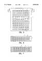
- FIG. 5is a plan view of the porous portion constituting the living body-supporting member in an example of the present invention.
- FIG. 6shows an example of a sectional view along the line A--A of FIG. 5.
- FIG. 7shows an example of a sectional view along the line B--B of FIG. 5.
- alumina powder having an average particle diameter of 0.4 ⁇ mwere added 0.3% by weight of dispersing material, 8% by weight of organic binder, 0.2% by weight of antifoaming agent, and 25% of water was added thereto to adjust a slip, which was used to prepare a tape having a thickness of 0.3 mm by a doctor blade method. This tape was cut to a desired size, and perforated by punching.
- pore patternsThere are two types of pore patterns, and one type is such that circular pores having a diameter of 1.0 mm are perforated at 1.5 mm pitches. Another type is that circular pores having a diameter of 2.0 mm are perforated at 3 mm pitches.
- FIG. 3shows femur component F of an artificial knee with porous body N bonded thereto prepared by the above-mentioned method.
- FIG. 4shows a ceramic implant D for dental applications with porous body N bonded to a bone-embedded portion prepared by the above-mentioned method.
- FIGS. 5-7show the structure of porous portions 1 of this living body-supporting member.
- apatite powder having an average diameter of 1 ⁇ mwere added 1.0% by weight of dispersing material, 5% by weight of organic binder, 0.5% by weight of antifoaming agent, and 20% of water was added thereto to prepare a slip, which was used to prepare a tape having a thickness of 0.05 mm by a doctor blade method.
- This tapewas subjected to punching as in Example 1 and laminated up to 20 layers so that pores could communicate with each other, to obtain a porous body.
- This porous bodywas fired at a temperature of 1300° C. in an oxidizing atmosphere, thus the living body-supporting member composed of apatite was obtained.
- a slipwhich was used to prepare a thin plate of 40 ⁇ 50 ⁇ 0.06 mm by a cast molding method.
- This thin platewas subjected to punching to make circular pores having a diameter of 0.5 mm at 1.0 mm pitches.
- Another typeis such that circular pores having a diameter of 0.5 mm were punched at 1.0 mm pitches.
- These two types of thin plateswere alternatively laminated up to 8 layers so that pores could communicate with each other to form a porous body. This porous body was bonded to the cast molded body prepared by the slip, dried, and fired at a temperature of 1450° C. in an oxidizing atmosphere.
- apatite powder having an average particle diameter of 1 ⁇ mwere added 1.0% by weight of dispensing material, 5% by weight or organic binder, 0.5% by weight of antifoaming agent, and 20% of water was added thereto to prepare a slip, which was used to prepare a tape having a thickness of 0.5 mm by a doctor blade method.
- This tapewas subjected to punching to make circular pores as in Example 1 and laminated up to 8 layers so that the pores could communicate with each other to obtain a porous body.
- a plate materialwas prepared by a cast molding method, by using an ultra-fine alumina raw material having a temporary diameter of 0.1 ⁇ m and an average particle diameter of 0.3 ⁇ m, whose firing temperature was 1300° C.
- the apatite bodywas bonded to this alumina molded body, which was dried and fired at a temperature of 1300° C. in an oxidizing atmosphere, thus the living body-supporting member which was an integrally fired two-layer structure comprising a surface layer composed of apatite porous portions 1 and a parent material composed of alumina dense portions.
- the range of the present inventionis not Limited by these examples, and the thickness of laminated green sheets may not be fixed, and may be optionally changed so far as it does not depart from the object of the present invention.
- porous portions constituting the surface layer of the living body-supporting member of the present inventionby forming multiple pores communicating with each other, while being displaced for every roughly certain depth, the bone reproduces and penetrates densely, thereby the living body-supporting member is coupled with the bond strongly so that there is no risk that it drops out from the supporting portion. Furthermore, by constituting the porous body with ceramics, even if the substrate is composed of ceramics, the substrate and the porous body can be integrally coupled with each other, thereby there is no risk that both of them can be separated. Furthermore, when the sliding face is composed of ceramics, the abrasiveness becomes excellent by the effect of the integral coupling.
- the present inventionapplies the multilayer technique of ceramics and also provides a method to perforate multiple pores in the green sheet of ceramic materials, to optionally laminate the green sheets so that the pores communicate with each other, and to fire it. According to this method, such an excellent effect can be exerted that the pore shapes of the porous body can be preliminarily designed so that the pores communicate with each other while being displaced for every certain depth, and it can be accurately controlled in the production thereof.
Landscapes
- Health & Medical Sciences (AREA)
- Chemical & Material Sciences (AREA)
- Life Sciences & Earth Sciences (AREA)
- Veterinary Medicine (AREA)
- Public Health (AREA)
- General Health & Medical Sciences (AREA)
- Oral & Maxillofacial Surgery (AREA)
- Transplantation (AREA)
- Animal Behavior & Ethology (AREA)
- Engineering & Computer Science (AREA)
- Dermatology (AREA)
- Epidemiology (AREA)
- Medicinal Chemistry (AREA)
- Inorganic Chemistry (AREA)
- Orthopedic Medicine & Surgery (AREA)
- Cardiology (AREA)
- Biomedical Technology (AREA)
- Heart & Thoracic Surgery (AREA)
- Vascular Medicine (AREA)
- Ceramic Engineering (AREA)
- Materials For Medical Uses (AREA)
- Prostheses (AREA)
- Compositions Of Oxide Ceramics (AREA)
Abstract
Description
Claims (13)
Applications Claiming Priority (2)
| Application Number | Priority Date | Filing Date | Title |
|---|---|---|---|
| JP6-323202 | 1994-12-26 | ||
| JP32320294AJP3450920B2 (en) | 1994-12-26 | 1994-12-26 | Method for manufacturing bioprosthesis member |
Publications (1)
| Publication Number | Publication Date |
|---|---|
| US6010336Atrue US6010336A (en) | 2000-01-04 |
Family
ID=18152188
Family Applications (1)
| Application Number | Title | Priority Date | Filing Date |
|---|---|---|---|
| US08/580,018Expired - LifetimeUS6010336A (en) | 1994-12-26 | 1995-12-20 | Living body-supporting member and preparation process thereof |
Country Status (4)
| Country | Link |
|---|---|
| US (1) | US6010336A (en) |
| EP (1) | EP0719529B1 (en) |
| JP (1) | JP3450920B2 (en) |
| DE (1) | DE69528346T2 (en) |
Cited By (33)
| Publication number | Priority date | Publication date | Assignee | Title |
|---|---|---|---|---|
| WO2002038083A1 (en)* | 2000-10-31 | 2002-05-16 | East Carolina University | Tissue lockable connecting structures |
| US6527810B2 (en) | 1997-10-01 | 2003-03-04 | Wright Medical Technology, Inc. | Bone substitutes |
| US20030065401A1 (en)* | 2001-01-25 | 2003-04-03 | Mark Amrich | Textured surface having undercut micro recesses in a surface |
| US20030065400A1 (en)* | 2001-04-12 | 2003-04-03 | Beam Heather Ann | Method and apparatus for engineered regenrative biostructures such as hydroxyapatite substrates for bone healing applications |
| US6599322B1 (en) | 2001-01-25 | 2003-07-29 | Tecomet, Inc. | Method for producing undercut micro recesses in a surface, a surgical implant made thereby, and method for fixing an implant to bone |
| US6620332B2 (en) | 2001-01-25 | 2003-09-16 | Tecomet, Inc. | Method for making a mesh-and-plate surgical implant |
| US20040254546A1 (en)* | 2001-11-06 | 2004-12-16 | Lefebvre Marc Andre' | Device for use in measuring and/or analysing at least one parameter of an external body portion |
| US20050085922A1 (en)* | 2003-10-17 | 2005-04-21 | Shappley Ben R. | Shaped filler for implantation into a bone void and methods of manufacture and use thereof |
| US20050100578A1 (en)* | 2003-11-06 | 2005-05-12 | Schmid Steven R. | Bone and tissue scaffolding and method for producing same |
| US20050112397A1 (en)* | 2003-07-24 | 2005-05-26 | Rolfe Jonathan L. | Assembled non-random foams |
| US6977095B1 (en) | 1997-10-01 | 2005-12-20 | Wright Medical Technology Inc. | Process for producing rigid reticulated articles |
| US20060224242A1 (en)* | 2003-04-16 | 2006-10-05 | Porex Surgical, Inc. | Craniofacial implant |
| US20080188857A1 (en)* | 2004-09-21 | 2008-08-07 | Lars Bruce | Method and Device For Improving the Fixing of a Prosthesis |
| US20100042167A1 (en)* | 2008-08-13 | 2010-02-18 | Nebosky Paul S | Orthopaedic screws |
| US20100042213A1 (en)* | 2008-08-13 | 2010-02-18 | Nebosky Paul S | Drug delivery implants |
| US20100042215A1 (en)* | 2008-08-13 | 2010-02-18 | Stalcup Gregory C | Orthopaedic implant |
| US20100042214A1 (en)* | 2008-08-13 | 2010-02-18 | Nebosky Paul S | Drug delivery implants |
| US20100042226A1 (en)* | 2008-08-13 | 2010-02-18 | Nebosky Paul S | Orthopaedic implant with spatially varying porosity |
| US20100075419A1 (en)* | 2006-09-26 | 2010-03-25 | Masahiko Inagaki | Biomaterial, method of constructing the same and use thereof |
| US20100114316A1 (en)* | 2003-04-16 | 2010-05-06 | Porex Surgical, Inc. | Craniofacial Implant |
| US20110082551A1 (en)* | 2007-11-27 | 2011-04-07 | Kilian Kraus | Intervertebral implant |
| US20110301709A1 (en)* | 2010-06-03 | 2011-12-08 | Kilian Kraus | Intervertebral implant |
| US20130006354A1 (en)* | 2010-02-26 | 2013-01-03 | Limacorporate Spa | Integrated prosthetic element |
| US9044195B2 (en) | 2013-05-02 | 2015-06-02 | University Of South Florida | Implantable sonic windows |
| US20150366668A1 (en)* | 2014-06-23 | 2015-12-24 | Community Blood Center | Cellular-scale surface modification for increased osteogenic protein expression |
| US9408699B2 (en) | 2013-03-15 | 2016-08-09 | Smed-Ta/Td, Llc | Removable augment for medical implant |
| US9681966B2 (en) | 2013-03-15 | 2017-06-20 | Smed-Ta/Td, Llc | Method of manufacturing a tubular medical implant |
| US9700431B2 (en) | 2008-08-13 | 2017-07-11 | Smed-Ta/Td, Llc | Orthopaedic implant with porous structural member |
| US9724203B2 (en) | 2013-03-15 | 2017-08-08 | Smed-Ta/Td, Llc | Porous tissue ingrowth structure |
| US9949837B2 (en) | 2013-03-07 | 2018-04-24 | Howmedica Osteonics Corp. | Partially porous bone implant keel |
| US10842645B2 (en) | 2008-08-13 | 2020-11-24 | Smed-Ta/Td, Llc | Orthopaedic implant with porous structural member |
| WO2024047318A1 (en)* | 2022-09-01 | 2024-03-07 | Universite D'artois | Surgical insert |
| FR3139275A1 (en)* | 2022-09-01 | 2024-03-08 | Universite D'artois | Surgical insert |
Families Citing this family (15)
| Publication number | Priority date | Publication date | Assignee | Title |
|---|---|---|---|---|
| WO1998038948A1 (en)* | 1997-03-04 | 1998-09-11 | Implico B.V. | An artefact suitable for use as a bone implant |
| JPH11178913A (en)* | 1997-12-22 | 1999-07-06 | Kyocera Corp | Bioprosthetic members |
| US20040081704A1 (en) | 1998-02-13 | 2004-04-29 | Centerpulse Biologics Inc. | Implantable putty material |
| WO2001003709A1 (en) | 1999-07-08 | 2001-01-18 | Cap Biotechnology, Inc. | Calcium-containing structures and methods of making and using the same |
| NL1016040C2 (en)* | 2000-08-29 | 2002-03-01 | Giles William Melsom | Porous cell attachment material, method for its manufacture, and applications. |
| US20020114795A1 (en) | 2000-12-22 | 2002-08-22 | Thorne Kevin J. | Composition and process for bone growth and repair |
| JP4540905B2 (en)* | 2001-11-13 | 2010-09-08 | Hoya株式会社 | Method for manufacturing sintered body |
| US7166133B2 (en) | 2002-06-13 | 2007-01-23 | Kensey Nash Corporation | Devices and methods for treating defects in the tissue of a living being |
| SE525787C2 (en)* | 2003-09-24 | 2005-04-26 | Nobel Biocare Ab | Procedure and apparatus for dental installation |
| US7718616B2 (en) | 2006-12-21 | 2010-05-18 | Zimmer Orthobiologics, Inc. | Bone growth particles and osteoinductive composition thereof |
| WO2012068135A1 (en) | 2010-11-15 | 2012-05-24 | Zimmer Orthobiologics, Inc. | Bone void fillers |
| CN105411725B (en)* | 2015-12-14 | 2018-04-20 | 宋占涛 | A kind of bone renovating material preparation method with more-dimensional channels structure |
| CN105380732B (en)* | 2015-12-14 | 2017-05-31 | 宋占涛 | Bone renovating material with more-dimensional channels structure |
| US20180271505A1 (en) | 2017-03-23 | 2018-09-27 | Ethicon, Inc. | Scaffolds for Joining Layers of Tissue at Discrete Points |
| CN115105641B (en)* | 2022-06-20 | 2023-06-02 | 四川大学 | A subcutaneous implant material capable of bony healing connection |
Citations (10)
| Publication number | Priority date | Publication date | Assignee | Title |
|---|---|---|---|---|
| US4990163A (en)* | 1989-02-06 | 1991-02-05 | Trustees Of The University Of Pennsylvania | Method of depositing calcium phosphate cermamics for bone tissue calcification enhancement |
| US5108432A (en)* | 1990-06-24 | 1992-04-28 | Pfizer Hospital Products Group, Inc. | Porous fixation surface |
| US5141510A (en)* | 1988-05-27 | 1992-08-25 | Shigehide Takagi | Structure of artificial bone material for use in implantation |
| US5222987A (en)* | 1989-04-12 | 1993-06-29 | Imperial Chemical Industries Plc | Composite material for use in a prosthetic device |
| JPH067388A (en)* | 1992-04-17 | 1994-01-18 | Kyocera Corp | Artificial prosthesis member and manufacturing method thereof |
| US5348788A (en)* | 1991-01-30 | 1994-09-20 | Interpore Orthopaedics, Inc. | Mesh sheet with microscopic projections and holes |
| US5380328A (en)* | 1993-08-09 | 1995-01-10 | Timesh, Inc. | Composite perforated implant structures |
| US5496372A (en)* | 1992-04-17 | 1996-03-05 | Kyocera Corporation | Hard tissue prosthesis including porous thin metal sheets |
| US5507814A (en)* | 1994-03-30 | 1996-04-16 | Northwestern University | Orthopedic implant with self-reinforced mantle |
| US5531794A (en)* | 1993-09-13 | 1996-07-02 | Asahi Kogaku Kogyo Kabushiki Kaisha | Ceramic device providing an environment for the promotion and formation of new bone |
Family Cites Families (10)
| Publication number | Priority date | Publication date | Assignee | Title |
|---|---|---|---|---|
| US4374669A (en) | 1975-05-09 | 1983-02-22 | Mac Gregor David C | Cardiovascular prosthetic devices and implants with porous systems |
| US4289719A (en) | 1976-12-10 | 1981-09-15 | International Business Machines Corporation | Method of making a multi-layer ceramic substrate |
| US4259072A (en) | 1977-04-04 | 1981-03-31 | Kyoto Ceramic Co., Ltd. | Ceramic endosseous implant |
| DE3414924A1 (en) | 1984-04-19 | 1985-10-31 | Klaus Dr.med. Dr.med.habil. 8000 München Draenert | COATED ANCHORAGE PART FOR IMPLANTS |
| JPS6131163A (en)* | 1984-07-23 | 1986-02-13 | 京セラ株式会社 | Ceramic bioprosthetic material and its manufacturing method |
| US5236459A (en) | 1989-09-06 | 1993-08-17 | Sulzer Brothers Limited | Bone implant and method of making same |
| ATE106222T1 (en)* | 1989-09-06 | 1994-06-15 | Sulzer Medizinaltechnik Ag | IMPLANT WITH ANCHORING PLATES FOR BONE TISSUE. |
| DE4205969C2 (en)* | 1992-02-27 | 1994-07-07 | Merck Patent Gmbh | Process for the production of moldings with a predetermined pore structure |
| US5296180A (en)* | 1992-05-11 | 1994-03-22 | Polyceramics, Inc. | Ceramic process |
| WO1994001377A1 (en)* | 1992-07-07 | 1994-01-20 | Toray Industries, Inc. | Ceramic green sheet |
- 1994
- 1994-12-26JPJP32320294Apatent/JP3450920B2/ennot_activeExpired - Lifetime
- 1995
- 1995-12-18DEDE69528346Tpatent/DE69528346T2/ennot_activeExpired - Lifetime
- 1995-12-18EPEP95119960Apatent/EP0719529B1/ennot_activeExpired - Lifetime
- 1995-12-20USUS08/580,018patent/US6010336A/ennot_activeExpired - Lifetime
Patent Citations (11)
| Publication number | Priority date | Publication date | Assignee | Title |
|---|---|---|---|---|
| US5141510A (en)* | 1988-05-27 | 1992-08-25 | Shigehide Takagi | Structure of artificial bone material for use in implantation |
| US4990163A (en)* | 1989-02-06 | 1991-02-05 | Trustees Of The University Of Pennsylvania | Method of depositing calcium phosphate cermamics for bone tissue calcification enhancement |
| US5222987A (en)* | 1989-04-12 | 1993-06-29 | Imperial Chemical Industries Plc | Composite material for use in a prosthetic device |
| US5108432A (en)* | 1990-06-24 | 1992-04-28 | Pfizer Hospital Products Group, Inc. | Porous fixation surface |
| US5348788A (en)* | 1991-01-30 | 1994-09-20 | Interpore Orthopaedics, Inc. | Mesh sheet with microscopic projections and holes |
| US5455100A (en)* | 1991-01-30 | 1995-10-03 | Interpore International | Porous articles and methods for producing same |
| JPH067388A (en)* | 1992-04-17 | 1994-01-18 | Kyocera Corp | Artificial prosthesis member and manufacturing method thereof |
| US5496372A (en)* | 1992-04-17 | 1996-03-05 | Kyocera Corporation | Hard tissue prosthesis including porous thin metal sheets |
| US5380328A (en)* | 1993-08-09 | 1995-01-10 | Timesh, Inc. | Composite perforated implant structures |
| US5531794A (en)* | 1993-09-13 | 1996-07-02 | Asahi Kogaku Kogyo Kabushiki Kaisha | Ceramic device providing an environment for the promotion and formation of new bone |
| US5507814A (en)* | 1994-03-30 | 1996-04-16 | Northwestern University | Orthopedic implant with self-reinforced mantle |
Cited By (64)
| Publication number | Priority date | Publication date | Assignee | Title |
|---|---|---|---|---|
| US6527810B2 (en) | 1997-10-01 | 2003-03-04 | Wright Medical Technology, Inc. | Bone substitutes |
| US20060093729A1 (en)* | 1997-10-01 | 2006-05-04 | Marx Jeffrey G | Process for producing rigid reticulated articles |
| US7740897B2 (en) | 1997-10-01 | 2010-06-22 | Wright Medical Technology, Inc. | Process for producing rigid reticulated articles |
| US6977095B1 (en) | 1997-10-01 | 2005-12-20 | Wright Medical Technology Inc. | Process for producing rigid reticulated articles |
| US20030236575A1 (en)* | 2000-10-31 | 2003-12-25 | Chang Yu | Tissue lockable connecting structures |
| WO2002038083A1 (en)* | 2000-10-31 | 2002-05-16 | East Carolina University | Tissue lockable connecting structures |
| US7083648B2 (en) | 2000-10-31 | 2006-08-01 | East Carolina University | Tissue lockable connecting structures |
| US7018418B2 (en) | 2001-01-25 | 2006-03-28 | Tecomet, Inc. | Textured surface having undercut micro recesses in a surface |
| US7850862B2 (en) | 2001-01-25 | 2010-12-14 | Tecomet Inc. | Textured surface having undercut micro recesses in a surface |
| US20030065401A1 (en)* | 2001-01-25 | 2003-04-03 | Mark Amrich | Textured surface having undercut micro recesses in a surface |
| US20030178387A1 (en)* | 2001-01-25 | 2003-09-25 | Mark Amrich | Method for making a mesh-and-plate surgical implant |
| US6620332B2 (en) | 2001-01-25 | 2003-09-16 | Tecomet, Inc. | Method for making a mesh-and-plate surgical implant |
| US6599322B1 (en) | 2001-01-25 | 2003-07-29 | Tecomet, Inc. | Method for producing undercut micro recesses in a surface, a surgical implant made thereby, and method for fixing an implant to bone |
| US20060129161A1 (en)* | 2001-01-25 | 2006-06-15 | Tecomet, Inc. | Textured surface having undercut micro recesses in a surface |
| US20030194869A1 (en)* | 2001-01-25 | 2003-10-16 | Amrich Mark P. | Method for producing undercut micro recesses in a surface, a surgical implant made thereby, and method for fixing an implant to bone |
| US7122057B2 (en) | 2001-04-12 | 2006-10-17 | Therics, Llc | Method and apparatus for engineered regenerative biostructures such as hydroxyapatite substrates for bone healing applications |
| US20030065400A1 (en)* | 2001-04-12 | 2003-04-03 | Beam Heather Ann | Method and apparatus for engineered regenrative biostructures such as hydroxyapatite substrates for bone healing applications |
| US20040254546A1 (en)* | 2001-11-06 | 2004-12-16 | Lefebvre Marc Andre' | Device for use in measuring and/or analysing at least one parameter of an external body portion |
| US8075483B2 (en)* | 2001-11-06 | 2011-12-13 | L'ORéAL S.A. | Device for use in measuring and/or analysing at least one parameter of an external body portion |
| US20060224242A1 (en)* | 2003-04-16 | 2006-10-05 | Porex Surgical, Inc. | Craniofacial implant |
| US8398720B2 (en) | 2003-04-16 | 2013-03-19 | Orthovita, Inc. | Craniofacial implant |
| US8298292B2 (en) | 2003-04-16 | 2012-10-30 | Howmedica Osteonics Corp. | Craniofacial implant |
| US20100114316A1 (en)* | 2003-04-16 | 2010-05-06 | Porex Surgical, Inc. | Craniofacial Implant |
| US7208222B2 (en) | 2003-07-24 | 2007-04-24 | Viasys Healthcare Inc. | Assembled non-random foams |
| US20050112397A1 (en)* | 2003-07-24 | 2005-05-26 | Rolfe Jonathan L. | Assembled non-random foams |
| US20050085922A1 (en)* | 2003-10-17 | 2005-04-21 | Shappley Ben R. | Shaped filler for implantation into a bone void and methods of manufacture and use thereof |
| US20050100578A1 (en)* | 2003-11-06 | 2005-05-12 | Schmid Steven R. | Bone and tissue scaffolding and method for producing same |
| US20080188857A1 (en)* | 2004-09-21 | 2008-08-07 | Lars Bruce | Method and Device For Improving the Fixing of a Prosthesis |
| US20100075419A1 (en)* | 2006-09-26 | 2010-03-25 | Masahiko Inagaki | Biomaterial, method of constructing the same and use thereof |
| US20110082551A1 (en)* | 2007-11-27 | 2011-04-07 | Kilian Kraus | Intervertebral implant |
| US8932356B2 (en) | 2007-11-27 | 2015-01-13 | Henning Kloss | Intervertebral implant |
| US9616205B2 (en) | 2008-08-13 | 2017-04-11 | Smed-Ta/Td, Llc | Drug delivery implants |
| US9700431B2 (en) | 2008-08-13 | 2017-07-11 | Smed-Ta/Td, Llc | Orthopaedic implant with porous structural member |
| US20100042215A1 (en)* | 2008-08-13 | 2010-02-18 | Stalcup Gregory C | Orthopaedic implant |
| US20100042213A1 (en)* | 2008-08-13 | 2010-02-18 | Nebosky Paul S | Drug delivery implants |
| US11426291B2 (en) | 2008-08-13 | 2022-08-30 | Smed-Ta/Td, Llc | Orthopaedic implant with porous structural member |
| US20100042167A1 (en)* | 2008-08-13 | 2010-02-18 | Nebosky Paul S | Orthopaedic screws |
| US8475505B2 (en) | 2008-08-13 | 2013-07-02 | Smed-Ta/Td, Llc | Orthopaedic screws |
| US8702767B2 (en) | 2008-08-13 | 2014-04-22 | Smed-Ta/Td, Llc | Orthopaedic Screws |
| US10842645B2 (en) | 2008-08-13 | 2020-11-24 | Smed-Ta/Td, Llc | Orthopaedic implant with porous structural member |
| US20100042214A1 (en)* | 2008-08-13 | 2010-02-18 | Nebosky Paul S | Drug delivery implants |
| US10357298B2 (en) | 2008-08-13 | 2019-07-23 | Smed-Ta/Td, Llc | Drug delivery implants |
| US10349993B2 (en) | 2008-08-13 | 2019-07-16 | Smed-Ta/Td, Llc | Drug delivery implants |
| US9358056B2 (en) | 2008-08-13 | 2016-06-07 | Smed-Ta/Td, Llc | Orthopaedic implant |
| US20100042226A1 (en)* | 2008-08-13 | 2010-02-18 | Nebosky Paul S | Orthopaedic implant with spatially varying porosity |
| US9561354B2 (en) | 2008-08-13 | 2017-02-07 | Smed-Ta/Td, Llc | Drug delivery implants |
| US8864826B2 (en)* | 2010-02-26 | 2014-10-21 | Limacorporate Spa | Integrated prosthetic element |
| US20130006354A1 (en)* | 2010-02-26 | 2013-01-03 | Limacorporate Spa | Integrated prosthetic element |
| US20110301709A1 (en)* | 2010-06-03 | 2011-12-08 | Kilian Kraus | Intervertebral implant |
| US11564801B2 (en) | 2013-03-07 | 2023-01-31 | Howmedica Osteonics Corp. | Partially porous tibial component |
| USD967960S1 (en) | 2013-03-07 | 2022-10-25 | Howmedica Osteonics Corp. | Porous tibial implant |
| US9949837B2 (en) | 2013-03-07 | 2018-04-24 | Howmedica Osteonics Corp. | Partially porous bone implant keel |
| US12343261B2 (en) | 2013-03-07 | 2025-07-01 | Howmedica Osteonics Corp. | Partially porous tibial component |
| US12279961B2 (en) | 2013-03-07 | 2025-04-22 | Howmedica Osteonics Corp. | Method of manufacturing a tibial implant |
| US12268609B2 (en) | 2013-03-07 | 2025-04-08 | Howmedica Osteonics Corp. | Method of manufacturing a tibial implant |
| US10449065B2 (en) | 2013-03-15 | 2019-10-22 | Smed-Ta/Td, Llc | Method of manufacturing a tubular medical implant |
| US9724203B2 (en) | 2013-03-15 | 2017-08-08 | Smed-Ta/Td, Llc | Porous tissue ingrowth structure |
| US9707080B2 (en) | 2013-03-15 | 2017-07-18 | Smed-Ta/Td, Llc | Removable augment for medical implant |
| US9681966B2 (en) | 2013-03-15 | 2017-06-20 | Smed-Ta/Td, Llc | Method of manufacturing a tubular medical implant |
| US9408699B2 (en) | 2013-03-15 | 2016-08-09 | Smed-Ta/Td, Llc | Removable augment for medical implant |
| US9044195B2 (en) | 2013-05-02 | 2015-06-02 | University Of South Florida | Implantable sonic windows |
| US20150366668A1 (en)* | 2014-06-23 | 2015-12-24 | Community Blood Center | Cellular-scale surface modification for increased osteogenic protein expression |
| WO2024047318A1 (en)* | 2022-09-01 | 2024-03-07 | Universite D'artois | Surgical insert |
| FR3139275A1 (en)* | 2022-09-01 | 2024-03-08 | Universite D'artois | Surgical insert |
Also Published As
| Publication number | Publication date |
|---|---|
| EP0719529A1 (en) | 1996-07-03 |
| EP0719529B1 (en) | 2002-09-25 |
| JP3450920B2 (en) | 2003-09-29 |
| DE69528346T2 (en) | 2003-07-31 |
| JPH08173463A (en) | 1996-07-09 |
| DE69528346D1 (en) | 2002-10-31 |
Similar Documents
| Publication | Publication Date | Title |
|---|---|---|
| US6010336A (en) | Living body-supporting member and preparation process thereof | |
| US20070116734A1 (en) | Porous, load-bearing, ceramic or metal implant | |
| US4969913A (en) | Ceramics composites | |
| US11141278B2 (en) | Surgical implants comprising graded porous structures | |
| US5071434A (en) | Biologically active surface ceramic and process for producing the same | |
| US20100217392A1 (en) | Reinforced ptfe medical barriers | |
| EP0834949A3 (en) | Laminated structures of sintered ceramic material, electrochemical cells, filters and process for producing such sintered laminated structures | |
| CA2419326A1 (en) | Method of making an orthopaedic implant having a porous metal surface | |
| GB2198356A (en) | Endosseous implants | |
| EP0107476A2 (en) | Bone graft substitute | |
| EP1024529A3 (en) | Green sheet and manufacturing method thereof, manufacturing method of multi-layer wiring board, and manufacturing method of double-sided wiring board | |
| US6776860B2 (en) | Ceramic composite and manufacturing method thereof | |
| WO2021021246A1 (en) | Synthetic tissue-graft scaffold | |
| JPH11178913A (en) | Bioprosthetic members | |
| KR101241642B1 (en) | Fabrication Method of a Novel Artificial Cortical Bone using a Multi-pass Extrusion Process | |
| JPH09173436A (en) | Bioprosthesis member and manufacturing method thereof | |
| JP3634974B2 (en) | Bioprosthetic material | |
| DE69328047T2 (en) | Prosthesis and process for its manufacture | |
| DE19709690A1 (en) | Multilayer ceramic body with monolithic structure | |
| KR100675324B1 (en) | Manufacturing method and photonic crystal of photonic crystal | |
| KR100426446B1 (en) | Cylindrical Porous Bone Filler and Process for Its Production | |
| KR20190055478A (en) | Titanium Structure Having Porous Structured, And Manufacturing Method Therefor | |
| KR102115225B1 (en) | One-step manufacturing method of laminated molding porous component | |
| ATE382958T1 (en) | METHOD AND DEVICE FOR PRODUCING MULTI-LAYER ACTUATORS | |
| JPH07184987A (en) | Artificial prosthesis member |
Legal Events
| Date | Code | Title | Description |
|---|---|---|---|
| AS | Assignment | Owner name:KYOCERA CORPORATION, JAPAN Free format text:ASSIGNMENT OF ASSIGNORS INTEREST;ASSIGNORS:SHIMOTOSO, TOSHIHIKO;TERUI, AKIRA;KITANO, HIROYUKI;REEL/FRAME:008205/0806 Effective date:19951213 | |
| AS | Assignment | Owner name:KYOCERA CORPORATION, JAPAN Free format text:(ASSIGNMENT OF ASSIGNOR'S INTEREST) RERECORD TO CORRECT THE RECORDATION DATE OF 03-14-96 TO 3-18-96, PREVIOUSLY RECORDED AT REEL 8205, FRAME 0806.;ASSIGNORS:SHIMOTOSO, TOSHIHIKO;TERUI, AKIRA;KITANO, HIROYUKI;REEL/FRAME:008212/0531 Effective date:19951213 Owner name:KYOCERA CORPORATION, JAPAN Free format text:ASSIGNMENT OF ASSIGNORS INTEREST;ASSIGNORS:SHIMOTOSO, TOSHIHIKO;TERUI, AKIRA;KITANO, HIROYUKI;REEL/FRAME:007852/0577 Effective date:19951213 | |
| STCF | Information on status: patent grant | Free format text:PATENTED CASE | |
| FEPP | Fee payment procedure | Free format text:PAYER NUMBER DE-ASSIGNED (ORIGINAL EVENT CODE: RMPN); ENTITY STATUS OF PATENT OWNER: LARGE ENTITY Free format text:PAYOR NUMBER ASSIGNED (ORIGINAL EVENT CODE: ASPN); ENTITY STATUS OF PATENT OWNER: LARGE ENTITY | |
| FPAY | Fee payment | Year of fee payment:4 | |
| FPAY | Fee payment | Year of fee payment:8 | |
| FPAY | Fee payment | Year of fee payment:12 |