US6010228A - Wireless emergency safety light with sensing means for conventional light switch or plug receptacle - Google Patents
Wireless emergency safety light with sensing means for conventional light switch or plug receptacleDownload PDFInfo
- Publication number
- US6010228A US6010228AUS08/969,788US96978897AUS6010228AUS 6010228 AUS6010228 AUS 6010228AUS 96978897 AUS96978897 AUS 96978897AUS 6010228 AUS6010228 AUS 6010228A
- Authority
- US
- United States
- Prior art keywords
- housing
- electrical
- switch
- replacement
- plug receptacle
- Prior art date
- Legal status (The legal status is an assumption and is not a legal conclusion. Google has not performed a legal analysis and makes no representation as to the accuracy of the status listed.)
- Expired - Lifetime
Links
- 230000004044responseEffects0.000claimsabstractdescription16
- 238000012360testing methodMethods0.000claimsdescription14
- 230000008901benefitEffects0.000description8
- 238000010586diagramMethods0.000description3
- 238000009429electrical wiringMethods0.000description3
- 238000005286illuminationMethods0.000description3
- 238000006424Flood reactionMethods0.000description1
- 230000004397blinkingEffects0.000description1
- 230000008859changeEffects0.000description1
- 230000000994depressogenic effectEffects0.000description1
- 230000005611electricityEffects0.000description1
- 238000001914filtrationMethods0.000description1
- 230000006872improvementEffects0.000description1
- 230000004048modificationEffects0.000description1
- 238000012986modificationMethods0.000description1
- 238000006467substitution reactionMethods0.000description1
Images


Classifications
- F—MECHANICAL ENGINEERING; LIGHTING; HEATING; WEAPONS; BLASTING
- F21—LIGHTING
- F21S—NON-PORTABLE LIGHTING DEVICES; SYSTEMS THEREOF; VEHICLE LIGHTING DEVICES SPECIALLY ADAPTED FOR VEHICLE EXTERIORS
- F21S9/00—Lighting devices with a built-in power supply; Systems employing lighting devices with a built-in power supply
- F21S9/02—Lighting devices with a built-in power supply; Systems employing lighting devices with a built-in power supply the power supply being a battery or accumulator
- F21S9/022—Emergency lighting devices
- F—MECHANICAL ENGINEERING; LIGHTING; HEATING; WEAPONS; BLASTING
- F21—LIGHTING
- F21V—FUNCTIONAL FEATURES OR DETAILS OF LIGHTING DEVICES OR SYSTEMS THEREOF; STRUCTURAL COMBINATIONS OF LIGHTING DEVICES WITH OTHER ARTICLES, NOT OTHERWISE PROVIDED FOR
- F21V23/00—Arrangement of electric circuit elements in or on lighting devices
- F21V23/04—Arrangement of electric circuit elements in or on lighting devices the elements being switches
- F21V23/0442—Arrangement of electric circuit elements in or on lighting devices the elements being switches activated by means of a sensor, e.g. motion or photodetectors
- H—ELECTRICITY
- H02—GENERATION; CONVERSION OR DISTRIBUTION OF ELECTRIC POWER
- H02J—CIRCUIT ARRANGEMENTS OR SYSTEMS FOR SUPPLYING OR DISTRIBUTING ELECTRIC POWER; SYSTEMS FOR STORING ELECTRIC ENERGY
- H02J9/00—Circuit arrangements for emergency or stand-by power supply, e.g. for emergency lighting
- H02J9/02—Circuit arrangements for emergency or stand-by power supply, e.g. for emergency lighting in which an auxiliary distribution system and its associated lamps are brought into service
- F—MECHANICAL ENGINEERING; LIGHTING; HEATING; WEAPONS; BLASTING
- F21—LIGHTING
- F21Y—INDEXING SCHEME ASSOCIATED WITH SUBCLASSES F21K, F21L, F21S and F21V, RELATING TO THE FORM OR THE KIND OF THE LIGHT SOURCES OR OF THE COLOUR OF THE LIGHT EMITTED
- F21Y2115/00—Light-generating elements of semiconductor light sources
- F21Y2115/10—Light-emitting diodes [LED]
- Y—GENERAL TAGGING OF NEW TECHNOLOGICAL DEVELOPMENTS; GENERAL TAGGING OF CROSS-SECTIONAL TECHNOLOGIES SPANNING OVER SEVERAL SECTIONS OF THE IPC; TECHNICAL SUBJECTS COVERED BY FORMER USPC CROSS-REFERENCE ART COLLECTIONS [XRACs] AND DIGESTS
- Y10—TECHNICAL SUBJECTS COVERED BY FORMER USPC
- Y10S—TECHNICAL SUBJECTS COVERED BY FORMER USPC CROSS-REFERENCE ART COLLECTIONS [XRACs] AND DIGESTS
- Y10S362/00—Illumination
- Y10S362/802—Position or condition responsive switch
Definitions
- the inventionrelates to a housing for a wireless emergency light source and, more particularly, a wireless emergency light source for automatically illuminating an area in response to a power failure.
- This inventionis a further improvement of the inventions set forth in U.S. Pat. No. 5,473,517 and U.S. application Ser. No. 08/566,677 and relates to a unit that replaces a conventional switch or plug receptacle for controlling any electrical load, such as a light fixture or appliance, in response to a power failure.
- Switch plate devices having an illumination source and/or having a rechargeable flashlight contained thereonare commercially available and have been disclosed in the prior art.
- U.S. Pat. No. 4,514,789discloses a housing on a switch plate having an LED to locate a light switch in the dark.
- U.S. Pat. No. 4,611,264discloses a housing adhesively attached to a switch plate having a light to locate the light switch in the dark. The housing can be removed and used as a flashlight.
- the prior art devicesdo not disclose a housing which is easily installable and mechanically connectable to a conventional light switch to provide automatic illumination to an area when a power failure occurs.
- Another object of the present inventionis to provide a housing for a wireless emergency safety light which is mechanically connectable to a conventional light switch.
- Another object of the present inventionis to provide a wireless emergency safety light which is battery operated and can operate with different types of light sources, such as LED lamps, a fluorescent lamp, an incandescent lamp, or an electroluminescent film.
- Another object of the present inventionis to provide a wireless emergency safety light which has an antenna sensing device for sensing a power failure and automatically actuating the emergency light source.
- Another object of the present inventionis to provide a wireless emergency safety light in which an antenna sensing device is capable of receiving a radio frequency signal that is emitted from all electrical wiring when electrical current is present, such that the antenna sensing device detects the presence and/or loss of electrical power and activates the wireless emergency safety light.
- a further object of the present inventionis to provide a multi-position switch for selecting a motion sensor, a timer, a night light, or a photocell.
- a still further object of the present inventionis to provide a housing for a wireless emergency safety light which can be mass produced in an automated and economical manner and is relatively inexpensive.
- the present inventionprovides a housing having a wireless emergency safety light which is mechanically connectable to a conventional electrical switch or a plug receptacle for providing power to a light fixture or other electrical load in response to a loss of electrical power.
- the housingreplaces a conventional switch plate having at least one opening for receiving the switch actuator of the light switch or for receiving the electrical plug receptacle.
- the emergency safety lightincludes at least one compartment in the housing for receiving batteries; a second compartment in the housing for receiving an emergency light source adapted to be connected to the batteries; and an antenna for sensing the loss of electrical power to the light switch and, response thereto, for actuating the emergency light source.
- FIG. 1is a front perspective view of the wireless emergency safety light of the first embodiment of the present invention showing the safety light in operational use with a single wall switch of a wall junction box;
- FIG. 2is an exploded front perspective view of the wireless emergency safety light of the first embodiment of the present invention showing the major component parts contained therein and in use with a wall junction box;
- FIG. 3is an exploded rear perspective view of the wireless emergency safety light of the first embodiment of the present invention showing the major component parts contained therein and with the lens cover section being connectable to the main housing;
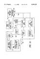
- FIG. 4is an electrical block diagram of the wireless emergency safety light of the present invention showing the major electrical components of the electrical assembly
- FIG. 5is an electrical circuit schematic diagram of the wireless emergency safety light of the present invention showing the major electrical circuit components contained therein of the electrical assembly;
- FIG. 6is a front perspective view of the wireless emergency safety light of the second embodiment of the present invention showing the safety light in operational use with a double wall switch of a wall junction box;
- FIG. 7is a front perspective view of the wireless emergency safety light of the third embodiment of the present invention showing the safety light in operational use with a large-sized rocker switch of a wall junction box;
- FIG. 8is a front view of the wireless emergency safety light of the fourth embodiment of the present invention showing the safety light in operational use with a double three-prong wall plug of a wall receptacle junction box;
- FIG. 9is a front view of the wireless emergency safety light of the fifth embodiment of the present invention showing the safety light in operational use with a standard size rocker switch of a wall junction box;
- FIG. 10is a front view of the wireless emergency safety light of the sixth embodiment of the present invention showing the safety light in operational use with a bottom switch of a wall junction box, and in use with a photocell sensor, a night light, and/or a motion sensor; and
- FIG. 11is an electrical functional diagram of the wireless emergency safety light of the present invention showing the major electrical components of the alternate electrical assembly.
- the wireless emergency safety light and its component parts of the first preferred embodiment 10 and its alternate embodiments 200, 300, 400, 500 and 600are represented in detail by FIGS. 1 through 11 of the drawings.
- the wireless emergency safety lights 10, 200, 300, 400, 500 and 600provide for automatic illumination of a pre-determined area when a power failure occurs.
- the alternate embodiments 200, 300, 400, 500 and 600differ from the first preferred embodiment 10 only in the design and configuration of the front wall 24 of housing 20 having an upper cavity section 38 therein which is different.
- the sixth embodiment 600further includes a photocell sensor 104, a motion sensor 106, and a night light within an alternate electrical assembly 80' for the wireless emergency safety light 600, as shown in FIG. 10 of the drawings.
- the wireless emergency safety lights 200, 300, 400, 500 and 600 of the alternate embodimentsfunction and operate in the same manner as the wireless emergency safety light 10 of the first preferred embodiment.
- the first embodiment of the present inventionprovides for a wireless emergency safety light 10, as represented in detail by FIGS. 1 through 5 of the drawings.
- the wireless emergency safety light 10includes a housing 20 having a lower lens cover section 22.
- the housing 20includes a front wall 24, side walls 26, 28 and 30, a bottom wall 32 for receiving the lens cover section 22, a rear wall 34, and an interior cavity 36 for holding in place an electrical assembly 80 therein.
- Front wall 24includes an upper cavity section 38 having a pair of mounting hole openings 40a and 40b for receiving mounting screws 42 for mounting housing 20 to the wall junction box assembly 120; and a rectangular shaped switch opening 44 for receiving wall switch 122 of the wall junction box assembly 120.
- front wall 24also includes a test switch opening 46 for receiving a test switch actuator 86 attached to electrical assembly 80.
- Mounting screws 42attach the wall junction box assembly 120 via mounting openings 124a and 124b of mounting brackets 126a and 126b, respectively.
- Rear wall 34 within the interior cavity 36further includes a pair of battery compartments 50 and 52 each having a battery spring contact board 54 and 56 and each having a battery contact back plate 58 and 60 for receiving a plurality of AA alkaline batteries 62, being used as the main power supply source in case of a power failure.
- rear wall 34also includes an integrally attached pair of slotted wall bracket holders 74a and 74b for holding in place the main PC board 88, and bracket holders 76a, 76b, 76c, and 76d for holding in place the LED PC board 92, as depicted in FIGS. 2 and 3 of the drawings.
- Lens cover section 22includes a front wall 64, side walls 66, 68, 70 and a bottom wall 72 for interfitting with the bottom wall 32 of housing 20, as shown in FIG. 3 of the drawings.
- Electrical assembly 80includes an antenna sensing device 82 for sensing the loss of electrical power to the junction wall box 120; a noise filter 84 for filtering out extraneous electrical signals; a logic gate(s) 85 for amplifying the signal transmitted from noise filter 84; a test switch 86 for testing of the various mode controls, stand by position or off position within the electrical assembly 80; a low battery detector 98, a pulse generator 99, and a low battery indicator drive 100.
- the main PC board 88provides for the electrical operation of these electrical components 82, 84, 85, 86, 98, 99, and 100 of electrical assembly 80.
- electrical assembly 80further includes a photocell or timer 90 for the option of turning "On" of the safety light 10 during night-time hours; an LED PC board 92; and an LED PC array component 94 having a plurality of LED lamps 96a to 96e.
- Wire 102provides the electrical connection between PC board 88, PC board 92, and LED PC array 94.
- the wireless emergency safety light of the second embodiment 200 of the present inventionis depicted in detail by FIG. 6 of the drawings. All aspects of the wireless emergency safety light 200 of the second embodiment are the same as the wireless emergency safety light 10 of the first embodiment, except for the design and configuration of the front wall 224 having an upper cavity section 238 of housing 220.
- Safety light 200includes a housing 220 having a front wall 224 with an upper cavity section 238.
- Upper cavity section 238includes a plurality of mounting hole openings 240a, 240b, 240c, and 240d for receiving mounting screws 42 for mounting housing 220 to the wall junction box assembly 210; and a pair of rectangular-shaped switch openings 244a and 244b for receiving wall switches 212a and 212b of the wall junction box assembly 210.
- the wireless emergency safety light 200 of the second embodimentfunctions and operates in use in the same manner as the wireless emergency safety light 10 of the first embodiment.
- the wireless emergency safety light of the third embodiment 300 of the present inventionis depicted in detail by FIG. 7 of the drawings. All aspects of the wireless emergency safety light 300 of the third embodiment are the same as the wireless emergency safety light 10 of the first embodiment, except for the design and configuration of the front wall 324 having an upper cavity section 338 of housing 320.
- Safety light 300includes a housing 320 having a front wall 324 with an upper cavity section 338.
- Front wall 324includes a pair of mounting hole openings 340a and 340b for receiving mounting screws 42 for mounting housing 320 to the wall junction box assembly 310.
- Upper cavity section 338includes a rectangular-shaped switch opening 344 for receiving one or more enlarged rocker switches 312 of the wall junction box assembly 310.
- the wireless emergency safety light 300 of the third embodimentfunctions and operates in use in the same manner as the wireless emergency safety light 10 of the first embodiment.
- the wireless emergency safety light of the fourth embodiment 400 of the present inventionis depicted in detail by FIG. 8 of the drawings. All aspects of the wireless emergency safety light 400 of the fourth embodiment are the same as the wireless emergency safety light 10 of the first embodiment, except for the design and configuration of the front wall 424 having an upper cavity section 438 of housing 420.
- Safety light 400includes a housing 420 having a front wall 424 with an upper cavity section 438.
- Upper cavity section 438includes a mounting hole opening 440 for receiving mounting screws 42 for mounting housing 420 to the wall receptacle junction box assembly 410; and a pair of substantially rectangular-shaped receptacle openings 444a and 444b for receiving two or more wall receptacles 412a and 412b, respectively, of the wall receptacle junction box assembly 410.
- safety light 400uses a plurality of incandescent lamps 108a to 108c in place of the LED lamps 96a to 96e of the wireless emergency safety light 10 for providing a light source when a power failure occurs.
- the wireless emergency safety light 400 of the fourth embodimentfunctions and operates in use in the same manner as the wireless emergency safety light 10 of the first embodiment.
- the wireless emergency safety light of the fifth embodiment 500 of the present inventionis depicted in detail by FIG. 9 of the drawings. All aspects of the wireless emergency safety light 500 of the fifth embodiment are the same as the wireless emergency safety light 10 of the first embodiment, except for the design and configuration of the front wall 524 having an upper cavity section 538 of housing 520.
- Safety light 500includes a housing 520 having a front wall 524 with an upper cavity section 538.
- Upper cavity section 538includes a pair of mounting hole openings 540a and 540b for receiving mounting screws 42 for mounting housing 520 to the wall junction box assembly 510, and a rectangular-shaped opening 544 for receiving a rocker switch 512 of wall junction box assembly 510.
- safety light 500uses a fluorescent lamp 110 in place of the LED lamps 96a to 96e of the wireless emergency safety light 10 for providing a light source when a power failure occurs.
- the wireless emergency safety light 500 of the fifth embodimentfunctions and operates in use in the same manner as the wireless emergency safety light 10 of the first embodiment.
- the wireless emergency safety light of the sixth embodiment 600 of the present inventionis depicted in detail by FIG. 10 of the drawings. All aspects of the wireless emergency safety light 600 of the sixth embodiment are the same as the wireless emergency safety light 10 of the first embodiment, except for the design and configuration of the front wall 624 having an upper cavity section 638 of housing 620, as well as additional electrical components of a photocell sensor 104 and a motion sensor 106 of the alternate electrical assembly 80'.
- Safety light 600includes a housing 620 having a front wall 624 with an upper cavity section 638.
- Upper cavity section 638includes a pair of mounting hole openings 640a and 640b for receiving mounting screws 42 for mounting housing 620 to the wall junction box assembly 610; and a rectangular-shaped opening 644 for receiving a button switch 612 of wall junction box assembly 610.
- safety light 600may use an electroluminescent device 112, instead of LED lamps 96a to 96e, for providing the emergency light source.
- the alternate electrical assembly 80'includes a photocell sensor 104 for automatically turning ON and OFF the LED lamps 96a to 96e when they are being used as a night light; and electrical assembly 80' also includes a motion sensor 106 for actuating the LED lamps 96a to 96e in response to when a person enters the room and passes the motion sensor 106.
- the wireless emergency safety light 600 of the sixth embodimentfunctions and operates in use in the same manner as the wireless emergency safety light 10 of the first embodiment.
- the wireless emergency safety light 10is a self-contained emergency lighting housing 20 that attaches to an existing wall switch junction box 120 or receptacle junction box 410, as shown in FIGS. 2 and 8 of the drawings.
- This safety light 10automatically turns on the emergency LED lamps 96a to 96e when the antenna sensing device 82 senses the loss of electrical power.
- the safety light 10is powered by four (4) replaceable AA alkaline batteries 62 which, in turn, power the flexible antenna sensing device 82 such that it will receive a radio frequency signal 101 that is emitted from all electrical wiring, as in a wall junction box 12, when electrical current is present.
- This antenna sensing device 82detects the presence and/or loss of power.
- the replaceable batteries 62are placed in the open battery compartments 50 and 52 by the user in the interior cavity 36 of the housing 20 and are held in place with battery spring clips 54 and 56.
- To install the unitthe consumer must first shut off the power to the electrical location so that the user may then install the safety light 10 in a safe manner.
- the userthen removes the two or more screws 42 that hold the existing switch plate (not shown) to the wall switch junction box 120 in the wall 12 (or the one or more screws 42 that hold the receptacle plate cover (not shown) to the wall 12).
- the consumerplaces the full length of the flexible insulated wire antenna sensing device 82 into the exposed junction box 120 making sure to place it close to the wiring in the wall junction box 120.
- the switch opening 44is then placed over the exposed wall switch(s) 122 (or receptacle(s) 412a and 412b) and attached with the same number of screws 42 originally removed.
- a test button or switch 86is included on the front wall 24 of the housing 20 for the consumer to test the batteries 62 by pressing this test button 86 and observing the LED lamps 96a to 96e being lit while the test button 86 is depressed.
- the wireless emergency safety light 10When the electrical assembly 80 is in its operational mode, the wireless emergency safety light 10 is in its ready and ON position, and if there is loss of power at the switch junction box 120, the following electrical sequence occurs.
- the antenna sensing device 82senses the loss of electrical power by the cessation of electrical pulses or electrical signals 101, whereas the noise filter 84 filters out extraneous electrical signals and high-frequency noise signals.
- noise filter 84emits a high logic level electrical signal (not shown), which is then received by the logic gates 85.
- the logic gates 85then act as a buffer and amplify the high logic level signal transmitted from the noise filter 84, and this amplified signal is transmitted to the switching transistor (Q1) 87.
- Transistor Q1(87) then turns on and supplies power to the LED PC array component 94.
- the LED PC array component 94then turns on the plurality of emergency LED lights 96a to 96e or the alternative emergency lights 108, 110, or 112.
- Electrical assembly 80'operates in a similar manner.
- the low battery detector 98 of electrical assembly 80notifies the user of this low battery level by the blinking of one of the LED lamps 96a to 96e or other light sources to notify the user that the batteries 62 have to be changed.
- a primary advantage of the present inventionis that it provides a simple and easily installable wireless emergency safety light which includes a fixedly-attached housing for the replacement of a standard switch plate or standard receptacle plate and which activates itself in response to a power failure of any kind.
- Another advantage of the present inventionis that it provides a housing for a wireless emergency safety light which is mechanically connectable to a conventional light switch.
- Another advantage of the present inventionis that it provides a wireless emergency safety light which is battery operated and can operate with different types of light sources, such as LED lamps, a fluorescent lamp, an incandescent lamp, or an electroluminescent film.
- Another advantage of the present inventionis that it provides a wireless emergency safety light which has an antenna sensing device for sensing a power failure and for automatically actuating the emergency light source.
- Another advantage of the present inventionis that it provides for a wireless emergency safety light in which an antenna sensing device is capable of receiving a radio frequency signal that is emitted from all electrical wiring when electrical current is present, such that the antenna sensing device detects the presence and/or loss of electrical power and activates the wireless emergency safety light.
- a further advantage of the present inventionis that it provides a multi-position switch for selecting a motion sensor, a timer, a night light, or a photocell.
- a still further advantage of the present inventionis that it provides a housing for a wireless emergency safety light which can be mass produced in an automated and economical manner and is relatively inexpensive.
Landscapes
- Engineering & Computer Science (AREA)
- General Engineering & Computer Science (AREA)
- Business, Economics & Management (AREA)
- Emergency Management (AREA)
- Power Engineering (AREA)
- Circuit Arrangement For Electric Light Sources In General (AREA)
- Arrangement Of Elements, Cooling, Sealing, Or The Like Of Lighting Devices (AREA)
Abstract
Description
The invention relates to a housing for a wireless emergency light source and, more particularly, a wireless emergency light source for automatically illuminating an area in response to a power failure.
This invention is a further improvement of the inventions set forth in U.S. Pat. No. 5,473,517 and U.S. application Ser. No. 08/566,677 and relates to a unit that replaces a conventional switch or plug receptacle for controlling any electrical load, such as a light fixture or appliance, in response to a power failure.
Frequently, homes, offices, and industrial plant facilities experience many types of emergency situations involving power failures where an interior or exterior area has no light. The power failures may be caused by electrical short circuits, brownouts, fire, accidents, natural disasters (i.e., floods, hurricanes, tornadoes, etc.), or a planned shutoff of electricity to a facility or dwelling. As a result of these emergencies, most facilities, and especially residential homes, do not have emergency generators to provide lighting, or they only have emergency lighting in the form of portable light sources, such as flashlights.
A need exists for a simple and easily installable wireless emergency light source which includes a fixedly-attached housing for replacement of standard switch plates and plug receptacles and which activates itself in response to a power failure of any kind.
Switch plate devices having an illumination source and/or having a rechargeable flashlight contained thereon are commercially available and have been disclosed in the prior art. For example, U.S. Pat. No. 4,514,789 discloses a housing on a switch plate having an LED to locate a light switch in the dark. U.S. Pat. No. 4,611,264 discloses a housing adhesively attached to a switch plate having a light to locate the light switch in the dark. The housing can be removed and used as a flashlight.
The prior art devices do not disclose a housing which is easily installable and mechanically connectable to a conventional light switch to provide automatic illumination to an area when a power failure occurs.
Accordingly, it is a primary object of the present invention to provide a simple and easily installable wireless emergency safety light which includes a housing for the replacement of a standard switch plate or standard receptacle plate and which activates itself in response to a power failure of any kind.
Another object of the present invention is to provide a housing for a wireless emergency safety light which is mechanically connectable to a conventional light switch.
Another object of the present invention is to provide a wireless emergency safety light which is battery operated and can operate with different types of light sources, such as LED lamps, a fluorescent lamp, an incandescent lamp, or an electroluminescent film.
Another object of the present invention is to provide a wireless emergency safety light which has an antenna sensing device for sensing a power failure and automatically actuating the emergency light source.
Another object of the present invention is to provide a wireless emergency safety light in which an antenna sensing device is capable of receiving a radio frequency signal that is emitted from all electrical wiring when electrical current is present, such that the antenna sensing device detects the presence and/or loss of electrical power and activates the wireless emergency safety light.
A further object of the present invention is to provide a multi-position switch for selecting a motion sensor, a timer, a night light, or a photocell.
A still further object of the present invention is to provide a housing for a wireless emergency safety light which can be mass produced in an automated and economical manner and is relatively inexpensive.
The present invention provides a housing having a wireless emergency safety light which is mechanically connectable to a conventional electrical switch or a plug receptacle for providing power to a light fixture or other electrical load in response to a loss of electrical power. The housing replaces a conventional switch plate having at least one opening for receiving the switch actuator of the light switch or for receiving the electrical plug receptacle. The emergency safety light includes at least one compartment in the housing for receiving batteries; a second compartment in the housing for receiving an emergency light source adapted to be connected to the batteries; and an antenna for sensing the loss of electrical power to the light switch and, response thereto, for actuating the emergency light source.
Further objects, features, and advantages of the present invention will become apparent upon consideration of the detailed description of the presently-preferred embodiments, when taken in conjunction with the accompanying drawings, wherein:
FIG. 1 is a front perspective view of the wireless emergency safety light of the first embodiment of the present invention showing the safety light in operational use with a single wall switch of a wall junction box;
FIG. 2 is an exploded front perspective view of the wireless emergency safety light of the first embodiment of the present invention showing the major component parts contained therein and in use with a wall junction box;
FIG. 3 is an exploded rear perspective view of the wireless emergency safety light of the first embodiment of the present invention showing the major component parts contained therein and with the lens cover section being connectable to the main housing;
FIG. 4 is an electrical block diagram of the wireless emergency safety light of the present invention showing the major electrical components of the electrical assembly;
FIG. 5 is an electrical circuit schematic diagram of the wireless emergency safety light of the present invention showing the major electrical circuit components contained therein of the electrical assembly;
FIG. 6 is a front perspective view of the wireless emergency safety light of the second embodiment of the present invention showing the safety light in operational use with a double wall switch of a wall junction box;
FIG. 7 is a front perspective view of the wireless emergency safety light of the third embodiment of the present invention showing the safety light in operational use with a large-sized rocker switch of a wall junction box;
FIG. 8 is a front view of the wireless emergency safety light of the fourth embodiment of the present invention showing the safety light in operational use with a double three-prong wall plug of a wall receptacle junction box;
FIG. 9 is a front view of the wireless emergency safety light of the fifth embodiment of the present invention showing the safety light in operational use with a standard size rocker switch of a wall junction box;
FIG. 10 is a front view of the wireless emergency safety light of the sixth embodiment of the present invention showing the safety light in operational use with a bottom switch of a wall junction box, and in use with a photocell sensor, a night light, and/or a motion sensor; and
FIG. 11 is an electrical functional diagram of the wireless emergency safety light of the present invention showing the major electrical components of the alternate electrical assembly.
The wireless emergency safety light and its component parts of the first preferredembodiment 10 and itsalternate embodiments emergency safety lights alternate embodiments embodiment 10 only in the design and configuration of the front wall 24 ofhousing 20 having an upper cavity section 38 therein which is different. Additionally, thesixth embodiment 600 further includes aphotocell sensor 104, amotion sensor 106, and a night light within an alternate electrical assembly 80' for the wirelessemergency safety light 600, as shown in FIG. 10 of the drawings. In all other respects, the wirelessemergency safety lights emergency safety light 10 of the first preferred embodiment.
The first embodiment of the present invention provides for a wirelessemergency safety light 10, as represented in detail by FIGS. 1 through 5 of the drawings. The wirelessemergency safety light 10 includes ahousing 20 having a lower lens cover section 22. Thehousing 20 includes a front wall 24,side walls 26, 28 and 30, a bottom wall 32 for receiving the lens cover section 22, a rear wall 34, and an interior cavity 36 for holding in place anelectrical assembly 80 therein. Front wall 24 includes an upper cavity section 38 having a pair of mounting hole openings 40a and 40b for receiving mounting screws 42 for mountinghousing 20 to the wall junction box assembly 120; and a rectangular shaped switch opening 44 for receiving wall switch 122 of the wall junction box assembly 120. In addition, front wall 24 also includes a test switch opening 46 for receiving atest switch actuator 86 attached toelectrical assembly 80. Mounting screws 42 attach the wall junction box assembly 120 via mounting openings 124a and 124b of mounting brackets 126a and 126b, respectively.
Rear wall 34 within the interior cavity 36 further includes a pair ofbattery compartments 50 and 52 each having a battery spring contact board 54 and 56 and each having a batterycontact back plate 58 and 60 for receiving a plurality of AAalkaline batteries 62, being used as the main power supply source in case of a power failure.
In addition, rear wall 34 also includes an integrally attached pair of slotted wall bracket holders 74a and 74b for holding in place themain PC board 88, and bracket holders 76a, 76b, 76c, and 76d for holding in place theLED PC board 92, as depicted in FIGS. 2 and 3 of the drawings.
Lens cover section 22 includes a front wall 64, side walls 66, 68, 70 and a bottom wall 72 for interfitting with the bottom wall 32 ofhousing 20, as shown in FIG. 3 of the drawings.
The wireless emergency safety light of the second embodiment 200 of the present invention is depicted in detail by FIG. 6 of the drawings. All aspects of the wireless emergency safety light 200 of the second embodiment are the same as the wirelessemergency safety light 10 of the first embodiment, except for the design and configuration of the front wall 224 having an upper cavity section 238 of housing 220. Safety light 200 includes a housing 220 having a front wall 224 with an upper cavity section 238. Upper cavity section 238 includes a plurality of mounting hole openings 240a, 240b, 240c, and 240d for receiving mounting screws 42 for mounting housing 220 to the wall junction box assembly 210; and a pair of rectangular-shaped switch openings 244a and 244b for receiving wall switches 212a and 212b of the wall junction box assembly 210. In all other respects, the wireless emergency safety light 200 of the second embodiment functions and operates in use in the same manner as the wirelessemergency safety light 10 of the first embodiment.
The wireless emergency safety light of thethird embodiment 300 of the present invention is depicted in detail by FIG. 7 of the drawings. All aspects of the wirelessemergency safety light 300 of the third embodiment are the same as the wirelessemergency safety light 10 of the first embodiment, except for the design and configuration of the front wall 324 having an upper cavity section 338 of housing 320.Safety light 300 includes a housing 320 having a front wall 324 with an upper cavity section 338. Front wall 324 includes a pair of mounting hole openings 340a and 340b for receiving mounting screws 42 for mounting housing 320 to the wall junction box assembly 310. Upper cavity section 338 includes a rectangular-shaped switch opening 344 for receiving one or more enlarged rocker switches 312 of the wall junction box assembly 310. In other respects, the wirelessemergency safety light 300 of the third embodiment functions and operates in use in the same manner as the wirelessemergency safety light 10 of the first embodiment.
The wireless emergency safety light of thefourth embodiment 400 of the present invention is depicted in detail by FIG. 8 of the drawings. All aspects of the wirelessemergency safety light 400 of the fourth embodiment are the same as the wirelessemergency safety light 10 of the first embodiment, except for the design and configuration of the front wall 424 having an upper cavity section 438 of housing 420.Safety light 400 includes a housing 420 having a front wall 424 with an upper cavity section 438. Upper cavity section 438 includes a mounting hole opening 440 for receiving mounting screws 42 for mounting housing 420 to the wall receptacle junction box assembly 410; and a pair of substantially rectangular-shaped receptacle openings 444a and 444b for receiving two or more wall receptacles 412a and 412b, respectively, of the wall receptacle junction box assembly 410. Additionally,safety light 400 uses a plurality of incandescent lamps 108a to 108c in place of theLED lamps 96a to 96e of the wirelessemergency safety light 10 for providing a light source when a power failure occurs. In all other respects, the wirelessemergency safety light 400 of the fourth embodiment functions and operates in use in the same manner as the wirelessemergency safety light 10 of the first embodiment.
The wireless emergency safety light of thefifth embodiment 500 of the present invention is depicted in detail by FIG. 9 of the drawings. All aspects of the wirelessemergency safety light 500 of the fifth embodiment are the same as the wirelessemergency safety light 10 of the first embodiment, except for the design and configuration of the front wall 524 having an upper cavity section 538 of housing 520.Safety light 500 includes a housing 520 having a front wall 524 with an upper cavity section 538. Upper cavity section 538 includes a pair of mounting hole openings 540a and 540b for receiving mounting screws 42 for mounting housing 520 to the wall junction box assembly 510, and a rectangular-shaped opening 544 for receiving a rocker switch 512 of wall junction box assembly 510. Additionally,safety light 500 uses a fluorescent lamp 110 in place of theLED lamps 96a to 96e of the wirelessemergency safety light 10 for providing a light source when a power failure occurs. In all other respects, the wirelessemergency safety light 500 of the fifth embodiment functions and operates in use in the same manner as the wirelessemergency safety light 10 of the first embodiment.
The wireless emergency safety light of thesixth embodiment 600 of the present invention is depicted in detail by FIG. 10 of the drawings. All aspects of the wirelessemergency safety light 600 of the sixth embodiment are the same as the wirelessemergency safety light 10 of the first embodiment, except for the design and configuration of the front wall 624 having an upper cavity section 638 of housing 620, as well as additional electrical components of aphotocell sensor 104 and amotion sensor 106 of the alternate electrical assembly 80'.
In addition, front wall 624 also include openings 646 and 648 for receiving thephotocell sensor 104 and themotion sensor 106, respectively.Safety light 600 includes a housing 620 having a front wall 624 with an upper cavity section 638. Upper cavity section 638 includes a pair of mounting hole openings 640a and 640b for receiving mounting screws 42 for mounting housing 620 to the wall junction box assembly 610; and a rectangular-shaped opening 644 for receiving a button switch 612 of wall junction box assembly 610. Alternatively,safety light 600 may use an electroluminescent device 112, instead ofLED lamps 96a to 96e, for providing the emergency light source.
The alternate electrical assembly 80', as shown in FIG. 11 of the drawings, includes aphotocell sensor 104 for automatically turning ON and OFF theLED lamps 96a to 96e when they are being used as a night light; and electrical assembly 80' also includes amotion sensor 106 for actuating theLED lamps 96a to 96e in response to when a person enters the room and passes themotion sensor 106. In all other respects, the wirelessemergency safety light 600 of the sixth embodiment functions and operates in use in the same manner as the wirelessemergency safety light 10 of the first embodiment.
In operation, the wirelessemergency safety light 10 is a self-containedemergency lighting housing 20 that attaches to an existing wall switch junction box 120 or receptacle junction box 410, as shown in FIGS. 2 and 8 of the drawings. Thissafety light 10 automatically turns on theemergency LED lamps 96a to 96e when theantenna sensing device 82 senses the loss of electrical power.
In use, thesafety light 10 is powered by four (4) replaceable AAalkaline batteries 62 which, in turn, power the flexibleantenna sensing device 82 such that it will receive aradio frequency signal 101 that is emitted from all electrical wiring, as in a wall junction box 12, when electrical current is present. Thisantenna sensing device 82 detects the presence and/or loss of power.
Thereplaceable batteries 62 are placed in the open battery compartments 50 and 52 by the user in the interior cavity 36 of thehousing 20 and are held in place with battery spring clips 54 and 56. To install the unit the consumer must first shut off the power to the electrical location so that the user may then install thesafety light 10 in a safe manner. The user then removes the two or more screws 42 that hold the existing switch plate (not shown) to the wall switch junction box 120 in the wall 12 (or the one or more screws 42 that hold the receptacle plate cover (not shown) to the wall 12). The consumer then places the full length of the flexible insulated wireantenna sensing device 82 into the exposed junction box 120 making sure to place it close to the wiring in the wall junction box 120. The switch opening 44 is then placed over the exposed wall switch(s) 122 (or receptacle(s) 412a and 412b) and attached with the same number of screws 42 originally removed.
Once the power is turned back on the wirelessemergency safety light 10 remains unlit and in the ready position to detect a power loss. A test button or switch 86 is included on the front wall 24 of thehousing 20 for the consumer to test thebatteries 62 by pressing thistest button 86 and observing theLED lamps 96a to 96e being lit while thetest button 86 is depressed.
When theelectrical assembly 80 is in its operational mode, the wirelessemergency safety light 10 is in its ready and ON position, and if there is loss of power at the switch junction box 120, the following electrical sequence occurs. Theantenna sensing device 82 senses the loss of electrical power by the cessation of electrical pulses orelectrical signals 101, whereas thenoise filter 84 filters out extraneous electrical signals and high-frequency noise signals. When the loss of electrical pulses occurs,noise filter 84 emits a high logic level electrical signal (not shown), which is then received by the logic gates 85. The logic gates 85 then act as a buffer and amplify the high logic level signal transmitted from thenoise filter 84, and this amplified signal is transmitted to the switching transistor (Q1) 87. Transistor Q1 (87) then turns on and supplies power to the LEDPC array component 94. The LEDPC array component 94 then turns on the plurality ofemergency LED lights 96a to 96e or the alternative emergency lights 108, 110, or 112. Electrical assembly 80' operates in a similar manner.
When thebatteries 62 start to lose their charge thelow battery detector 98 ofelectrical assembly 80 notifies the user of this low battery level by the blinking of one of theLED lamps 96a to 96e or other light sources to notify the user that thebatteries 62 have to be changed.
Accordingly, a primary advantage of the present invention is that it provides a simple and easily installable wireless emergency safety light which includes a fixedly-attached housing for the replacement of a standard switch plate or standard receptacle plate and which activates itself in response to a power failure of any kind.
Another advantage of the present invention is that it provides a housing for a wireless emergency safety light which is mechanically connectable to a conventional light switch.
Another advantage of the present invention is that it provides a wireless emergency safety light which is battery operated and can operate with different types of light sources, such as LED lamps, a fluorescent lamp, an incandescent lamp, or an electroluminescent film.
Another advantage of the present invention is that it provides a wireless emergency safety light which has an antenna sensing device for sensing a power failure and for automatically actuating the emergency light source.
Another advantage of the present invention is that it provides for a wireless emergency safety light in which an antenna sensing device is capable of receiving a radio frequency signal that is emitted from all electrical wiring when electrical current is present, such that the antenna sensing device detects the presence and/or loss of electrical power and activates the wireless emergency safety light.
A further advantage of the present invention is that it provides a multi-position switch for selecting a motion sensor, a timer, a night light, or a photocell.
A still further advantage of the present invention is that it provides a housing for a wireless emergency safety light which can be mass produced in an automated and economical manner and is relatively inexpensive.
A latitude of modification, change, and substitution is intended in the foregoing disclosure, and in some instances, some features of the invention will be employed without a corresponding use of other features. Accordingly, it is appropriate that the appended claims be construed broadly and in a manner consistent with the spirit and scope of the invention herein.
Claims (30)
1. A housing for an emergency light source which is mechanically connectable to an electrical switch having a switch actuator or a plug receptacle for providing power to a light fixture or other electrical load, comprising:
a) a replacement housing for replacement of a conventional switch plate or conventional plate for a plug receptacle, said replacement housing having at least one opening for receiving said switch actuator of said electrical switch or for receiving said electrical plug receptacle; means for mechanically connecting said replacement housing to said electrical switch or said plug receptacle; said replacement housing having no electrical connection to said conventional switch plate or to said plug receptacle;
b) at least one compartment in said replacement housing for receiving batteries;
c) a second compartment in said replacement housing for receiving an emergency light source adapted to be connected to said batteries; and
d) wireless means for sensing the loss of electrical power to said electrical switch or said plug receptacle and, in response thereto, for actuating said emergency light source.
2. A housing in accordance with claim 1, wherein said wireless means for sensing includes an antenna for sensing the loss of electrical power.
3. A housing in accordance with claim 1, wherein said replacement housing includes a pair of compartments for receiving batteries.
4. A housing in accordance with claim 3, wherein said pair of compartments are adapted to receive two "AA" batteries each.
5. A housing in accordance with claim 1, wherein said second compartment is adapted to receive one or more LED lamps, incandescent lamps, fluorescent lamps, or electroluminescent devices as said emergency light source.
6. A housing in accordance with claim 1, further including a PC board containing said wireless means for sensing.
7. A housing in accordance with claim 1, further including a manual test switch for testing the functioning of said emergency light source.
8. A housing in accordance with claim 1, wherein said replacement housing includes a switch plate cover having at least one light switch opening or a receptacle cover having at least one pair of receptacle openings.
9. A housing in accordance with claim 1, wherein said replacement housing includes a diffuser cover for diffusing light from said light source.
10. A housing in accordance with claim 1, wherein said replacement housing includes a compartment for receiving at least one printed circuit board.
11. A housing in accordance with claim 1, further including a photocell for controlling said emergency light source.
12. A housing for an emergency light source which is mechanically connectable to an electrical switch having a switch actuator or a plug receptacle for providing power to a light fixture or other electrical load, comprising:
a) a replacement housing for replacement of a conventional switch plate having at least one opening for receiving said switch actuator of said electrical switch or for receiving said electrical plug receptacle; means for mechanically connecting said replacement housing to said electrical switch or said plug receptacle; said replacement housing having no electrical connection to said conventional switch plate or to said plug receptacle;
b) at least one compartment in said replacement housing for receiving batteries;
c) a second compartment in said replacement housing for receiving an emergency light source adapted to be connected to said batteries;
d) wireless means for sensing the loss of electrical power to said electrical switch or said plug receptacle and, in response thereto, for actuating said emergency light source; and
e) a night light mounted in said replacement housing.
13. A housing in accordance with claim 12, wherein said wireless means for sensing includes an antenna for sensing the loss of electrical power.
14. A housing in accordance with claim 12, wherein said second compartment is adapted to receive one or more LED lamps, incandescent lamps, fluorescent lamps, or electroluminescent devices as said emergency light source.
15. A housing for an emergency light source which is mechanically connectable to an electrical switch having a switch actuator for a plug receptacle for providing power to a light fixture or other electrical load, comprising:
a) a replacement housing for replacement of conventional switch plate having at least one opening for receiving said switch actuator of said electrical switch or for receiving said electrical plug receptacle; means for mechanically connecting said replacement housing to said electrical switch or said plug receptacle; said replacement housing having no electrical connection to said conventional switch plate or to said plug receptacle;
b) at least one compartment in said replacement housing for receiving batteries;
c) a second compartment in said replacement housing for receiving an emergency light source adapted to be connected to said batteries;
d) wireless means for sensing the loss of electrical power to said electrical switch or said plug receptacle and, in response thereto, for actuating said emergency light source;
e) a night light mounted in said replacement housing;
f) a photocell mounted in said replacement housing for actuating said electrical switch or said plug receptacle in response to a power failure and when there is no ambient light; and
g) a timer mounted in said replacement housing for controlling the time that the batteries are operating.
16. A housing in accordance with claim 15, further including a manual test switch for testing the functioning of said emergency light source.
17. A housing in accordance with claim 15, further including a photocell for controlling said night light.
18. A housing in accordance with claim 15, wherein said wireless means for sensing includes an antenna for sensing the loss of electrical power.
19. A housing in accordance with claim 15, wherein said second compartment is adapted to receive one or more LED lamps, incandescent lamps, fluorescent lamps, or electroluminescent devices as said emergency light source.
20. A housing for an emergency light source which is mechanically connectable to an electrical switch having a switch actuator or a plug receptacle for providing power to a light fixture or other electrical load, comprising:
a) a replacement housing for replacement of a conventional switch plate having at least one opening for receiving said switch actuator of said electrical switch or for receiving said electrical plug receptacle;
b) means for connecting batteries to said replacement housing;
c) a compartment in said replacement housing for receiving an emergency light source adapted to be connected to said batteries;
d) wireless means for sensing the loss of electrical power to said electrical switch or said plug receptacle and, in response thereto, for actuating said emergency light source;
e) means for mechanically connecting said replacement housing to said electrical switch or said plug receptacle; said replacement housing having no electrical connection to said conventional switch plate or to said plug receptacle;
f) a motion sensor mounted in said replacement housing for actuating said emergency light source in response to an actuating movement;
g) a timer mounted in said replacement housing for controlling the amount of time said batteries operate;
h) a photocell mounted in said replacement housing for actuating said electrical switch or said plug receptacle in response to a power failure and when there is no ambient light; and
i) a switch for selecting said motion sensor, said timer or said photocell for controlling said electrical switch or said plug receptacle.
21. A housing in accordance with claim 20, further including a manual test switch for testing the functioning of said emergency light source.
22. A housing in accordance with claim 20, further including a night light and a photocell for controlling said night light.
23. A housing in accordance with claim 20, wherein said timer is a digital timer.
24. A housing in accordance with claim 20, wherein said wireless means for sensing includes an antenna for sensing the loss of electrical power.
25. A housing in accordance with claim 20, wherein said second compartment is adapted to receive one or more LED lamps, incandescent lamps, fluorescent lamps, or electroluminescent devices as said emergency light source.
26. A housing in accordance with claim 2, wherein said wireless means for sensing further includes a noise filter for emitting an electrical signal; at least one logic gate for receiving and amplifying said electrical signal from said noise filter; a switching transistor for receiving and transmitting said electrical signal to a LED PC device; and said LED PC device for turning on and supplying power to said light source.
27. A housing in accordance with claim 1, wherein said means for mechanically connecting said replacement housing to said electrical switch or said plug receptacle include a plurality of mounting screws.
28. A housing in accordance with claim 12, wherein said means for mechanically connecting said replacement housing to said electrical switch or said plug receptacle include a plurality of mounting screws.
29. A housing in accordance with claim 15, wherein said means for mechanically connecting said replacement housing to said electrical switch or said plug receptacle include a plurality of mounting screws.
30. A housing in accordance with claim 20, wherein said means for mechanically connecting said replacement housing to said electrical switch or said plug receptacle include a plurality of mounting screws.
Priority Applications (1)
| Application Number | Priority Date | Filing Date | Title |
|---|---|---|---|
| US08/969,788US6010228A (en) | 1997-11-13 | 1997-11-13 | Wireless emergency safety light with sensing means for conventional light switch or plug receptacle |
Applications Claiming Priority (1)
| Application Number | Priority Date | Filing Date | Title |
|---|---|---|---|
| US08/969,788US6010228A (en) | 1997-11-13 | 1997-11-13 | Wireless emergency safety light with sensing means for conventional light switch or plug receptacle |
Publications (1)
| Publication Number | Publication Date |
|---|---|
| US6010228Atrue US6010228A (en) | 2000-01-04 |
Family
ID=25516009
Family Applications (1)
| Application Number | Title | Priority Date | Filing Date |
|---|---|---|---|
| US08/969,788Expired - LifetimeUS6010228A (en) | 1997-11-13 | 1997-11-13 | Wireless emergency safety light with sensing means for conventional light switch or plug receptacle |
Country Status (1)
| Country | Link |
|---|---|
| US (1) | US6010228A (en) |
Cited By (168)
| Publication number | Priority date | Publication date | Assignee | Title |
|---|---|---|---|---|
| US20020050807A1 (en)* | 2000-08-02 | 2002-05-02 | Janik Craig M. | Device docking apparatus and method for using the same |
| US20020149929A1 (en)* | 2001-04-16 | 2002-10-17 | Cyberlux Corporation | Apparatus and methods for providing emergency lighting |
| USD469339S1 (en) | 1999-11-16 | 2003-01-28 | Lionel V. Luu | Wall plate having night light |
| US6547411B1 (en) | 2001-11-16 | 2003-04-15 | Timothy J. Dornbusch | Illuminated outlet |
| US20030205566A1 (en)* | 2000-09-15 | 2003-11-06 | Walter Evanyk | Appliance for dispensing melt adhesive with variable duty cycle and method of implementing |
| US20040016741A1 (en)* | 2000-09-15 | 2004-01-29 | Walter Evanyk | Appliance for liquefying solder with variable duty cycle and method of implementing |
| US6732449B2 (en) | 2000-09-15 | 2004-05-11 | Walter Evanyk | Dryer/blower appliance with efficient waste heat dissipation |
| US20040145912A1 (en)* | 2003-01-24 | 2004-07-29 | Chien Chao Chuan | Power outlet with night-vision-function |
| US6805469B1 (en)* | 2003-05-03 | 2004-10-19 | R A Barton | Concealed safety lighting device |
| US20040218379A1 (en)* | 2003-05-03 | 2004-11-04 | Mr. Robert Barton | Concealed Safety Lighting Device |
| US20050010954A1 (en)* | 2003-07-09 | 2005-01-13 | Serconet Ltd. | Modular outlet |
| US20050008033A1 (en)* | 2000-04-18 | 2005-01-13 | Serconet Ltd. | Telephone communication system over a single telephone line |
| US20050007024A1 (en)* | 2002-01-30 | 2005-01-13 | Cyberlux Corporation | Apparatus and methods for providing an emergency lighting augmentation system |
| US20050025162A1 (en)* | 2002-11-13 | 2005-02-03 | Yehuda Binder | Addressable outlet, and a network using same |
| US20050045826A1 (en)* | 1998-10-30 | 2005-03-03 | Stephen Barone | Motion detectors and occupancy sensors with improved sensitivity, angular resolution and range |
| US20050063403A1 (en)* | 2001-07-05 | 2005-03-24 | Serconet Ltd. | Telephone outlet with packet telephony adaptor, and a network using same |
| US6883927B2 (en)* | 2000-01-31 | 2005-04-26 | Cube Investments Limited | Frame assembly and light for an electrical wall conduit |
| US20050111636A1 (en)* | 1999-07-20 | 2005-05-26 | Serconet, Ltd | Network for telephony and data communication |
| US20050180561A1 (en)* | 2004-02-16 | 2005-08-18 | Serconet Ltd. | Outlet add-on module |
| US20050195594A1 (en)* | 2004-03-05 | 2005-09-08 | Kurtz John D. | Emergency light |
| US20050233633A1 (en)* | 2004-10-01 | 2005-10-20 | Tseng-Lu Chien | Outlet adaptor with EL elements |
| US20060018338A1 (en)* | 1998-07-28 | 2006-01-26 | Serconet, Ltd. | Local area network of serial intelligent cells |
| USD515449S1 (en) | 2005-06-10 | 2006-02-21 | Intermatic, Incorporated | Power failure switch warning light |
| USD515448S1 (en) | 2005-06-10 | 2006-02-21 | Intermatic, Incorporated | Power failure warning light |
| USD515960S1 (en) | 2005-06-10 | 2006-02-28 | Intermatic Incorporated | Power failure directional warning light |
| USD515959S1 (en) | 2005-06-10 | 2006-02-28 | Intermatic Incorporated | Power failure receptacle warning light |
| US20060098638A1 (en)* | 2001-10-11 | 2006-05-11 | Serconet Ltd. | Outlet with analog signal adapter, a method for use thereof and a network using said outlet |
| US20060170380A1 (en)* | 2003-10-14 | 2006-08-03 | Cyberlux Corporation | Apparatus and methods for providing emergency safety lighting |
| US20060197428A1 (en)* | 2005-02-21 | 2006-09-07 | Takeshi Tonegawa | Electron devices with non-evaporation-type getters and method for manufacturing the same |
| US20060262462A1 (en)* | 2003-05-03 | 2006-11-23 | Robert Barton | Concealed Safety Lighting and Alerting System |
| US20060278816A1 (en)* | 2005-06-09 | 2006-12-14 | Booty Donald J | Portable mountable indoor lamp having a positionable lamp head and motion and light sensors which can be aimed |
| US20070045276A1 (en)* | 2005-08-16 | 2007-03-01 | Gary Fisher | Flameless lighter |
| US7213932B1 (en)* | 2003-01-09 | 2007-05-08 | Pass & Seymour, Inc. | Electrical device with lamp module |
| US20070171625A1 (en)* | 2006-01-21 | 2007-07-26 | Glazner Gregory F | Switchplate Area Light |
| US20070229250A1 (en)* | 2006-03-28 | 2007-10-04 | Wireless Lighting Technologies, Llc | Wireless lighting |
| US20070291469A1 (en)* | 2006-06-15 | 2007-12-20 | Wen-Pin Chen | Switch panel assembly with a light-guiding rod |
| US20080073117A1 (en)* | 2006-09-26 | 2008-03-27 | Donald Lowell Misener | Configurable safety light receptacle |
| US20080169176A1 (en)* | 2007-01-11 | 2008-07-17 | Hsiu-Ling Yang | Push-button switch structure with illumination function |
| US20080198628A1 (en)* | 2007-02-15 | 2008-08-21 | Unity Opto Technology Co., Ltd. | Night light type switch assembly |
| US20080239701A1 (en)* | 2007-03-28 | 2008-10-02 | Holageo Enterprise Co., Ltd. | Emergency light |
| US20080258628A1 (en)* | 2007-04-17 | 2008-10-23 | Cree, Inc. | Light Emitting Diode Emergency Lighting Methods and Apparatus |
| US20090059603A1 (en)* | 2007-08-30 | 2009-03-05 | Wireless Environment, Llc | Wireless light bulb |
| US20090072970A1 (en)* | 2007-09-19 | 2009-03-19 | Barton Robert A | Safety system and method for conventional lighting fixtures |
| US20090180274A1 (en)* | 2006-01-21 | 2009-07-16 | Nite Ize, Inc. | Switch plate area light |
| US7581844B1 (en)* | 2008-03-24 | 2009-09-01 | Hsiu-Ling Yang | Switch cover plate with lighting mechanism |
| US7586718B1 (en)* | 2004-03-05 | 2009-09-08 | Pass & Seymour, Inc. | Electrical device with circuit protection component and light |
| US20090284384A1 (en)* | 2003-05-03 | 2009-11-19 | Barton Robert A | Unobtrusive Power Failure Lighting System |
| EP2149744A1 (en)* | 2008-07-31 | 2010-02-03 | Humankind Limited | Safety lighting |
| US20100033950A1 (en)* | 2008-08-06 | 2010-02-11 | Becky Farrell | Switchplate with nightlight |
| WO2010045643A1 (en)* | 2008-10-17 | 2010-04-22 | Manifold Products, Llc | Energy monitoring device |
| US20100102960A1 (en)* | 2008-10-24 | 2010-04-29 | Altair Engineering, Inc. | Integration of led lighting control with emergency notification systems |
| US20100141153A1 (en)* | 2006-03-28 | 2010-06-10 | Recker Michael V | Wireless lighting devices and applications |
| US7758234B1 (en)* | 2005-10-03 | 2010-07-20 | Pass & Seymour, Inc. | Electrical lighting device |
| USD620185S1 (en) | 2009-12-22 | 2010-07-20 | Osram Sylvania Inc. | Lamp |
| US20100237781A1 (en)* | 2009-03-19 | 2010-09-23 | Scott Dupre | Wireless convenience lighting system and method of making same |
| US20100271802A1 (en)* | 2006-03-28 | 2010-10-28 | Recker Michael V | Wireless lighting devices and grid-shifting applications |
| US20100327766A1 (en)* | 2006-03-28 | 2010-12-30 | Recker Michael V | Wireless emergency lighting system |
| US20110007496A1 (en)* | 2003-01-14 | 2011-01-13 | Tseng-Lu Chien | Led or laser project light has more than 1 functions |
| US7873058B2 (en) | 2004-11-08 | 2011-01-18 | Mosaid Technologies Incorporated | Outlet with analog signal adapter, a method for use thereof and a network using said outlet |
| US7938555B1 (en) | 2008-01-07 | 2011-05-10 | Kalhofer Richard | Emergency preparedness lamp |
| US20110187517A1 (en)* | 2010-01-29 | 2011-08-04 | Roths Andrew J | Safety Warning Light |
| US8003886B1 (en)* | 1996-05-02 | 2011-08-23 | Rintz William J | Light switch assembly |
| US20120268919A1 (en)* | 2010-09-09 | 2012-10-25 | Hsiu-Ling Yang | Switch panel illumination structure |
| WO2012150589A1 (en)* | 2011-05-03 | 2012-11-08 | Galtronics Corporation Ltd. | Antenna combined with lighting device |
| US20130088846A1 (en)* | 2011-10-07 | 2013-04-11 | Patno Enterprise, Llc | Lighting System |
| US8582598B2 (en) | 1999-07-07 | 2013-11-12 | Mosaid Technologies Incorporated | Local area network for distributing data communication, sensing and control signals |
| US20140185325A1 (en)* | 2012-12-29 | 2014-07-03 | Mary Elle Fashions, Inc. | Led night-light |
| US8807785B2 (en) | 2008-05-23 | 2014-08-19 | Ilumisys, Inc. | Electric shock resistant L.E.D. based light |
| US8840282B2 (en) | 2010-03-26 | 2014-09-23 | Ilumisys, Inc. | LED bulb with internal heat dissipating structures |
| US8866396B2 (en) | 2000-02-11 | 2014-10-21 | Ilumisys, Inc. | Light tube and power supply circuit |
| US8894430B2 (en) | 2010-10-29 | 2014-11-25 | Ilumisys, Inc. | Mechanisms for reducing risk of shock during installation of light tube |
| US8901823B2 (en) | 2008-10-24 | 2014-12-02 | Ilumisys, Inc. | Light and light sensor |
| US8928025B2 (en) | 2007-12-20 | 2015-01-06 | Ilumisys, Inc. | LED lighting apparatus with swivel connection |
| ITTV20130120A1 (en)* | 2013-07-31 | 2015-02-01 | Xtiore Innovazione & Tecnologia S R L | LIGHTING APPARATUS STRUCTURE. |
| US8946996B2 (en) | 2008-10-24 | 2015-02-03 | Ilumisys, Inc. | Light and light sensor |
| US9013119B2 (en) | 2010-03-26 | 2015-04-21 | Ilumisys, Inc. | LED light with thermoelectric generator |
| US9066393B2 (en) | 2006-03-28 | 2015-06-23 | Wireless Environment, Llc | Wireless power inverter for lighting |
| US9074736B2 (en) | 2006-03-28 | 2015-07-07 | Wireless Environment, Llc | Power outage detector and transmitter |
| US9083126B2 (en) | 2006-09-26 | 2015-07-14 | Calm Technologies Inc. | Configurable safety light receptacle |
| US9101026B2 (en) | 2008-10-24 | 2015-08-04 | Ilumisys, Inc. | Integration of LED lighting with building controls |
| US9107269B2 (en) | 2012-03-09 | 2015-08-11 | C-M Glo, Llc | Emergency lighting device |
| US9163794B2 (en) | 2012-07-06 | 2015-10-20 | Ilumisys, Inc. | Power supply assembly for LED-based light tube |
| US9184518B2 (en) | 2012-03-02 | 2015-11-10 | Ilumisys, Inc. | Electrical connector header for an LED-based light |
| US20150380984A1 (en)* | 2014-06-25 | 2015-12-31 | Raymond J. Lewis | Emergency lighting system |
| US20160003429A1 (en)* | 2007-05-31 | 2016-01-07 | Tseng-Lu Chien | Multiple Functions LED Night Light |
| US9271367B2 (en) | 2012-07-09 | 2016-02-23 | Ilumisys, Inc. | System and method for controlling operation of an LED-based light |
| US9267650B2 (en) | 2013-10-09 | 2016-02-23 | Ilumisys, Inc. | Lens for an LED-based light |
| US9285084B2 (en) | 2013-03-14 | 2016-03-15 | Ilumisys, Inc. | Diffusers for LED-based lights |
| US9353939B2 (en) | 2008-10-24 | 2016-05-31 | iLumisys, Inc | Lighting including integral communication apparatus |
| WO2016124917A1 (en)* | 2015-02-04 | 2016-08-11 | Wi-Innovate Ltd | Wireless control and sensing apparatus and method for an emergency luminaire |
| US9510400B2 (en) | 2014-05-13 | 2016-11-29 | Ilumisys, Inc. | User input systems for an LED-based light |
| US9574717B2 (en) | 2014-01-22 | 2017-02-21 | Ilumisys, Inc. | LED-based light with addressed LEDs |
| US9583977B1 (en) | 2013-05-02 | 2017-02-28 | Crystal Beranek Enterprises LLC | Back-up lamp light system |
| USD790091S1 (en) | 2012-12-29 | 2017-06-20 | Mary Elle Fashions, Inc. | LED night-light |
| JP2017112050A (en)* | 2015-12-18 | 2017-06-22 | 株式会社カネヒロデンシ | Led power failure lamp and using method of the led power failure lamp |
| US9742111B2 (en) | 2011-08-01 | 2017-08-22 | Snaprays Llc | Active cover plates |
| US9755374B2 (en) | 2010-09-07 | 2017-09-05 | Snaprays, Llc | Wall socket plates and signal boosters and systems and methods thereof |
| USD796707S1 (en) | 2012-12-29 | 2017-09-05 | Mary Elle Fashions, Inc. | LED night-light |
| US9832841B2 (en) | 2016-01-18 | 2017-11-28 | Snap Rays LLC | Wall-plate-switch system and method |
| US9832849B2 (en)* | 2015-06-12 | 2017-11-28 | Edward Villaume | Emergency light devices, systems, and methods |
| US9871324B2 (en) | 2011-08-01 | 2018-01-16 | Snap Rays LLC | Active cover plates |
| US9882318B2 (en) | 2011-08-01 | 2018-01-30 | Snaprays Llc | Active cover plates |
| US9882361B2 (en) | 2011-08-01 | 2018-01-30 | Snaprays Llc | Active cover plates |
| RU2643364C1 (en)* | 2014-07-04 | 2018-02-01 | Филипс Лайтинг Холдинг Б.В. | Light block with built-in antenna |
| US9899814B2 (en) | 2011-08-01 | 2018-02-20 | Snaprays Llc | Active cover plates |
| US9917430B2 (en) | 2011-08-01 | 2018-03-13 | Snap Rays | Active cover plates |
| USD819426S1 (en) | 2013-10-29 | 2018-06-05 | Snaprays, Llc | Lighted wall plate |
| US10034359B2 (en) | 2006-03-28 | 2018-07-24 | Wireless Environment, Llc | Cloud-connected off-grid lighting and video system |
| US10085332B2 (en) | 2006-03-28 | 2018-09-25 | A9.Com, Inc. | Motion sensitive communication device for controlling lighting |
| US10082257B1 (en) | 2013-05-02 | 2018-09-25 | Crystal Beranek Enterprises LLC | Back-up lamp light system |
| US10109945B2 (en) | 2017-02-17 | 2018-10-23 | Snaprays, Llc | Active cover plates |
| US10139790B2 (en) | 2015-06-10 | 2018-11-27 | Vivint, Inc. | Powered faceplate integration |
| US10161568B2 (en) | 2015-06-01 | 2018-12-25 | Ilumisys, Inc. | LED-based light with canted outer walls |
| USD842075S1 (en) | 2017-06-20 | 2019-03-05 | Snaprays, Llc | Light switch cover plate |
| USD842076S1 (en) | 2017-06-20 | 2019-03-05 | Snaprays, Llc | Light switch cover plate |
| USD847608S1 (en) | 2017-06-20 | 2019-05-07 | Snaprays, Llc | Light switch cover plate |
| US10291007B2 (en) | 2012-10-30 | 2019-05-14 | Snaprays Llc | Active cover plates |
| USD849511S1 (en) | 2017-06-20 | 2019-05-28 | Snaprays Llc | Light switch cover plate |
| USD849513S1 (en) | 2017-06-20 | 2019-05-28 | Snaprays Llc | Light switch cover plate |
| USD849512S1 (en) | 2017-06-20 | 2019-05-28 | Snaprays Llc | Light switch cover plate |
| USD849510S1 (en) | 2017-06-20 | 2019-05-28 | Snaprays Llc | Light switch cover plate |
| US10344929B1 (en) | 2017-09-01 | 2019-07-09 | Heathco, Llc | Battery backup for lighting system |
| US10373773B2 (en) | 2017-02-17 | 2019-08-06 | Snaprays Llc | Active cover plates |
| US10381789B2 (en) | 2011-08-01 | 2019-08-13 | Snaprays Llc | Active cover plates |
| US10381788B2 (en) | 2011-08-01 | 2019-08-13 | Snaprays Llc | Active cover plates |
| US10418813B1 (en) | 2017-04-01 | 2019-09-17 | Smart Power Partners LLC | Modular power adapters and methods of implementing modular power adapters |
| USD877599S1 (en) | 2017-06-20 | 2020-03-10 | Snaprays Llc | Light switch cover plate |
| US10601244B2 (en) | 2006-03-28 | 2020-03-24 | A9.Com, Inc. | Emergency lighting device with remote lighting |
| USD882377S1 (en) | 2011-09-06 | 2020-04-28 | Snaprays Llc | Lighted wall plate |
| US10644461B2 (en) | 2011-08-01 | 2020-05-05 | Snaprays Llc | Modified electrical devices |
| US10704776B2 (en) | 2017-11-17 | 2020-07-07 | Promier Products Inc. | Sliding light switch with integrated light source |
| US10727731B1 (en) | 2017-04-01 | 2020-07-28 | Smart Power Partners, LLC | Power adapters adapted to receive a module and methods of implementing power adapters with modules |
| US10803715B2 (en) | 2018-07-23 | 2020-10-13 | Abb Schweiz Ag | Intelligent emergency evacuation system |
| USD904319S1 (en) | 2018-11-16 | 2020-12-08 | Promier Products Inc. | Light switch with sliding actuator and integrated light source |
| US10917956B1 (en) | 2019-06-30 | 2021-02-09 | Smart Power Partners LLC | Control attachment configured to provide power to a load and method of configuring a control attachment |
| US10938168B2 (en) | 2019-06-30 | 2021-03-02 | Smart Power Partners LLC | In-wall power adapter and method of controlling the application of power to a load |
| US10958020B1 (en) | 2019-06-30 | 2021-03-23 | Smart Power Partners LLC | Control attachment for an in-wall power adapter and method of controlling an in-wall power adapter |
| US10958026B1 (en) | 2019-06-30 | 2021-03-23 | Smart Power Partners LLC | Contactless thermometer for an in-wall power adapter |
| US10965068B1 (en) | 2019-06-30 | 2021-03-30 | Smart Power Partners LLC | In-wall power adapter having an outlet and method of controlling an in-wall power adapter |
| US10986165B2 (en) | 2004-01-13 | 2021-04-20 | May Patents Ltd. | Information device |
| US10996645B1 (en) | 2017-04-01 | 2021-05-04 | Smart Power Partners LLC | Modular power adapters and methods of implementing modular power adapters |
| US11043768B1 (en) | 2019-06-30 | 2021-06-22 | Smart Power Partners LLC | Power adapter configured to provide power to a load and method of implementing a power adapter |
| US11158982B2 (en) | 2011-08-01 | 2021-10-26 | Snaprays Llc | Active cover plates |
| US11189948B1 (en) | 2019-06-30 | 2021-11-30 | Smart Power Partners LLC | Power adapter and method of implementing a power adapter to provide power to a load |
| US11201444B1 (en) | 2019-06-30 | 2021-12-14 | Smart Power Partners LLC | Power adapter having contact elements in a recess and method of controlling a power adapter |
| US11219108B1 (en) | 2019-06-30 | 2022-01-04 | Smart Power Partners LLC | Power adapter arrangement and method of implementing a power adapter arrangement |
| US11231730B1 (en) | 2019-06-30 | 2022-01-25 | Smart Power Power LLC | Control attachment for a power adapter configured to control power applied to a load |
| US11264769B1 (en) | 2019-06-30 | 2022-03-01 | Smart Power Partners LLC | Power adapter having contact elements in a recess and method of controlling a power adapter |
| US11274813B2 (en)* | 2018-12-13 | 2022-03-15 | Opple Lighting Co., Ltd. | Light source switching module, light source assembly and lighting lamp |
| US20220221117A1 (en)* | 2021-01-11 | 2022-07-14 | Eaton Intelligent Power Limited | Electrical devices with lights and associated zone-synchronizable lighting systems with back-up power and related methods |
| US11460874B1 (en) | 2019-06-30 | 2022-10-04 | Smart Power Partners LLC | In-wall power adapter configured to control the application of power to a load |
| US11476626B2 (en) | 2008-11-12 | 2022-10-18 | Aaron Chien | DC powered remote control LED light-bar assembly |
| US11523488B1 (en) | 2006-03-28 | 2022-12-06 | Amazon Technologies, Inc. | Wirelessly controllable communication module |
| US11579640B1 (en) | 2019-06-30 | 2023-02-14 | Smart Power Partners LLC | Control attachment for an in-wall power adapter |
| US11664631B2 (en) | 2011-08-01 | 2023-05-30 | Snaprays, Llc | Environment sensing active units |
| US20230184400A1 (en)* | 2021-12-15 | 2023-06-15 | Je Woo Corporation, Ltd. | Emergency lamp |
| US11812195B2 (en) | 2004-07-06 | 2023-11-07 | Aaron Chien | Multiple functions LED night light |
| US11888301B2 (en) | 2011-08-01 | 2024-01-30 | Snaprays, Llc | Active cover plates |
| US12021335B2 (en) | 2017-02-17 | 2024-06-25 | Snaprays, Llc | Active cover plates |
| US12027968B2 (en) | 2017-04-01 | 2024-07-02 | John J. King | Power adapters and methods of implementing a power adapter |
| US12045071B1 (en) | 2019-06-30 | 2024-07-23 | Smart Power Partners LLC | In-wall power adapter having an outlet |
| USD1038895S1 (en)* | 2021-01-05 | 2024-08-13 | Brilliant Home Technology, Inc. | Wall-mountable control device with illuminable feature |
| US12066848B1 (en) | 2019-06-30 | 2024-08-20 | Smart Power Partners LLC | In-wall power adaper adapted to receive a control attachment and method of implementing a power adapter |
| US12093004B1 (en) | 2017-04-01 | 2024-09-17 | Smart Power Partners LLC | In-wall power adapter and method of implementing an in-wall power adapter |
| US12142880B2 (en) | 2011-08-01 | 2024-11-12 | Snaprays, Llc | Active cover plates |
| US12155164B2 (en) | 2021-11-03 | 2024-11-26 | Smart Power Partners LLC | In-wall power adapter having a switch and a connector for controlling the application of a voltage |
| US12164350B1 (en) | 2019-06-30 | 2024-12-10 | Smart Power Partners LLC | Power adapter configured to provide power to a load |
| US12331896B2 (en) | 2010-04-30 | 2025-06-17 | Aaron Chien | LED plug-in outlet or DC power light has LED-unit(s) |
Citations (7)
| Publication number | Priority date | Publication date | Assignee | Title |
|---|---|---|---|---|
| US4001803A (en)* | 1975-10-01 | 1977-01-04 | Lombardo Dominick A | Lighting devices |
| US4514789A (en)* | 1984-03-07 | 1985-04-30 | Jester Michael H | Illuminated light switch plate with LED and oscillator circuit |
| US4631649A (en)* | 1985-10-16 | 1986-12-23 | Chloride Systems, a division of Chloride Power Electronics, Incorporated | Plug-in emergency light fixture |
| US4982176A (en)* | 1990-01-17 | 1991-01-01 | Frank Schwarz | Solar powered lighting and alarm systems activated by motion detection |
| US5309145A (en)* | 1992-05-01 | 1994-05-03 | Samsonite Corporation | Travel convenience and security device |
| US5473517A (en)* | 1995-01-23 | 1995-12-05 | Blackman; Stephen E. | Emergency safety light |
| US5523927A (en)* | 1994-12-29 | 1996-06-04 | Gokey; James A. | Illuminated animal collar |
- 1997
- 1997-11-13USUS08/969,788patent/US6010228A/ennot_activeExpired - Lifetime
Patent Citations (7)
| Publication number | Priority date | Publication date | Assignee | Title |
|---|---|---|---|---|
| US4001803A (en)* | 1975-10-01 | 1977-01-04 | Lombardo Dominick A | Lighting devices |
| US4514789A (en)* | 1984-03-07 | 1985-04-30 | Jester Michael H | Illuminated light switch plate with LED and oscillator circuit |
| US4631649A (en)* | 1985-10-16 | 1986-12-23 | Chloride Systems, a division of Chloride Power Electronics, Incorporated | Plug-in emergency light fixture |
| US4982176A (en)* | 1990-01-17 | 1991-01-01 | Frank Schwarz | Solar powered lighting and alarm systems activated by motion detection |
| US5309145A (en)* | 1992-05-01 | 1994-05-03 | Samsonite Corporation | Travel convenience and security device |
| US5523927A (en)* | 1994-12-29 | 1996-06-04 | Gokey; James A. | Illuminated animal collar |
| US5473517A (en)* | 1995-01-23 | 1995-12-05 | Blackman; Stephen E. | Emergency safety light |
Cited By (367)
| Publication number | Priority date | Publication date | Assignee | Title |
|---|---|---|---|---|
| US8003886B1 (en)* | 1996-05-02 | 2011-08-23 | Rintz William J | Light switch assembly |
| US7221679B2 (en) | 1998-07-28 | 2007-05-22 | Serconet Ltd. | Local area network of serial intelligent cells |
| US20060018338A1 (en)* | 1998-07-28 | 2006-01-26 | Serconet, Ltd. | Local area network of serial intelligent cells |
| US20060062241A1 (en)* | 1998-07-28 | 2006-03-23 | Serconet, Ltd | Local area network of serial intelligent cells |
| US8867523B2 (en) | 1998-07-28 | 2014-10-21 | Conversant Intellectual Property Management Incorporated | Local area network of serial intelligent cells |
| US7986708B2 (en) | 1998-07-28 | 2011-07-26 | Mosaid Technologies Incorporated | Local area network of serial intelligent cells |
| US7965735B2 (en) | 1998-07-28 | 2011-06-21 | Mosaid Technologies Incorporated | Local area network of serial intelligent cells |
| US8885660B2 (en) | 1998-07-28 | 2014-11-11 | Conversant Intellectual Property Management Incorporated | Local area network of serial intelligent cells |
| US8885659B2 (en) | 1998-07-28 | 2014-11-11 | Conversant Intellectual Property Management Incorporated | Local area network of serial intelligent cells |
| US8908673B2 (en) | 1998-07-28 | 2014-12-09 | Conversant Intellectual Property Management Incorporated | Local area network of serial intelligent cells |
| US20060092962A1 (en)* | 1998-07-28 | 2006-05-04 | Serconet, Ltd | Local area network of serial intelligent cells |
| US7053374B2 (en)* | 1998-10-30 | 2006-05-30 | Electro-Optic Technologies, Llc | Motion detectors and occupancy sensors with improved sensitivity, angular resolution and range |
| US20050045826A1 (en)* | 1998-10-30 | 2005-03-03 | Stephen Barone | Motion detectors and occupancy sensors with improved sensitivity, angular resolution and range |
| US8582598B2 (en) | 1999-07-07 | 2013-11-12 | Mosaid Technologies Incorporated | Local area network for distributing data communication, sensing and control signals |
| US20080292073A1 (en)* | 1999-07-20 | 2008-11-27 | Serconet, Ltd | Network for telephony and data communication |
| US8351582B2 (en) | 1999-07-20 | 2013-01-08 | Mosaid Technologies Incorporated | Network for telephony and data communication |
| US7483524B2 (en) | 1999-07-20 | 2009-01-27 | Serconet, Ltd | Network for telephony and data communication |
| US20050111636A1 (en)* | 1999-07-20 | 2005-05-26 | Serconet, Ltd | Network for telephony and data communication |
| US8929523B2 (en) | 1999-07-20 | 2015-01-06 | Conversant Intellectual Property Management Inc. | Network for telephony and data communication |
| USD469339S1 (en) | 1999-11-16 | 2003-01-28 | Lionel V. Luu | Wall plate having night light |
| US6883927B2 (en)* | 2000-01-31 | 2005-04-26 | Cube Investments Limited | Frame assembly and light for an electrical wall conduit |
| US9803806B2 (en) | 2000-02-11 | 2017-10-31 | Ilumisys, Inc. | Light tube and power supply circuit |
| US9416923B1 (en) | 2000-02-11 | 2016-08-16 | Ilumisys, Inc. | Light tube and power supply circuit |
| US10054270B2 (en) | 2000-02-11 | 2018-08-21 | Ilumisys, Inc. | Light tube and power supply circuit |
| US9006993B1 (en) | 2000-02-11 | 2015-04-14 | Ilumisys, Inc. | Light tube and power supply circuit |
| US10557593B2 (en) | 2000-02-11 | 2020-02-11 | Ilumisys, Inc. | Light tube and power supply circuit |
| US9006990B1 (en) | 2000-02-11 | 2015-04-14 | Ilumisys, Inc. | Light tube and power supply circuit |
| US9222626B1 (en) | 2000-02-11 | 2015-12-29 | Ilumisys, Inc. | Light tube and power supply circuit |
| US8870412B1 (en) | 2000-02-11 | 2014-10-28 | Ilumisys, Inc. | Light tube and power supply circuit |
| US8866396B2 (en) | 2000-02-11 | 2014-10-21 | Ilumisys, Inc. | Light tube and power supply circuit |
| US9970601B2 (en) | 2000-02-11 | 2018-05-15 | Ilumisys, Inc. | Light tube and power supply circuit |
| US9777893B2 (en) | 2000-02-11 | 2017-10-03 | Ilumisys, Inc. | Light tube and power supply circuit |
| US9759392B2 (en) | 2000-02-11 | 2017-09-12 | Ilumisys, Inc. | Light tube and power supply circuit |
| US9752736B2 (en) | 2000-02-11 | 2017-09-05 | Ilumisys, Inc. | Light tube and power supply circuit |
| US9746139B2 (en) | 2000-02-11 | 2017-08-29 | Ilumisys, Inc. | Light tube and power supply circuit |
| US9739428B1 (en) | 2000-02-11 | 2017-08-22 | Ilumisys, Inc. | Light tube and power supply circuit |
| US7466722B2 (en) | 2000-04-18 | 2008-12-16 | Serconet Ltd | Telephone communication system over a single telephone line |
| US8559422B2 (en) | 2000-04-18 | 2013-10-15 | Mosaid Technologies Incorporated | Telephone communication system over a single telephone line |
| US20060182095A1 (en)* | 2000-04-18 | 2006-08-17 | Serconet Ltd. | Telephone communication system over a single telephone line |
| US20060182094A1 (en)* | 2000-04-18 | 2006-08-17 | Serconet Ltd. | Telephone communication system over a single telephone line |
| US7397791B2 (en) | 2000-04-18 | 2008-07-08 | Serconet, Ltd. | Telephone communication system over a single telephone line |
| US7593394B2 (en) | 2000-04-18 | 2009-09-22 | Mosaid Technologies Incorporated | Telephone communication system over a single telephone line |
| US8223800B2 (en) | 2000-04-18 | 2012-07-17 | Mosaid Technologies Incorporated | Telephone communication system over a single telephone line |
| US20080043646A1 (en)* | 2000-04-18 | 2008-02-21 | Serconet Ltd. | Telephone communication system over a single telephone line |
| US8000349B2 (en) | 2000-04-18 | 2011-08-16 | Mosaid Technologies Incorporated | Telephone communication system over a single telephone line |
| US20050117603A1 (en)* | 2000-04-18 | 2005-06-02 | Serconet, Ltd. | Telephone communication system over a single telephone line |
| US20050008033A1 (en)* | 2000-04-18 | 2005-01-13 | Serconet Ltd. | Telephone communication system over a single telephone line |
| US7197028B2 (en) | 2000-04-18 | 2007-03-27 | Serconet Ltd. | Telephone communication system over a single telephone line |
| US6864798B2 (en)* | 2000-08-02 | 2005-03-08 | Simple Devices | Device docking apparatus and method for using the same |
| US20020050807A1 (en)* | 2000-08-02 | 2002-05-02 | Janik Craig M. | Device docking apparatus and method for using the same |
| US6732449B2 (en) | 2000-09-15 | 2004-05-11 | Walter Evanyk | Dryer/blower appliance with efficient waste heat dissipation |
| US20030205566A1 (en)* | 2000-09-15 | 2003-11-06 | Walter Evanyk | Appliance for dispensing melt adhesive with variable duty cycle and method of implementing |
| US20040016741A1 (en)* | 2000-09-15 | 2004-01-29 | Walter Evanyk | Appliance for liquefying solder with variable duty cycle and method of implementing |
| US6891130B2 (en) | 2000-09-15 | 2005-05-10 | Walter Evanyk | Appliance for dispensing melt adhesive with variable duty cycle and method of implementing |
| US6946623B2 (en) | 2000-09-15 | 2005-09-20 | Powerpulse Technologies, L.P. | Appliance for liquefying solder with variable duty cycle and method of implementing |
| US20020149929A1 (en)* | 2001-04-16 | 2002-10-17 | Cyberlux Corporation | Apparatus and methods for providing emergency lighting |
| US6752515B2 (en) | 2001-04-16 | 2004-06-22 | Cyberlux Corporation | Apparatus and methods for providing emergency lighting |
| US7680255B2 (en) | 2001-07-05 | 2010-03-16 | Mosaid Technologies Incorporated | Telephone outlet with packet telephony adaptor, and a network using same |
| US20050063403A1 (en)* | 2001-07-05 | 2005-03-24 | Serconet Ltd. | Telephone outlet with packet telephony adaptor, and a network using same |
| US7953071B2 (en) | 2001-10-11 | 2011-05-31 | Mosaid Technologies Incorporated | Outlet with analog signal adapter, a method for use thereof and a network using said outlet |
| US7860084B2 (en) | 2001-10-11 | 2010-12-28 | Mosaid Technologies Incorporated | Outlet with analog signal adapter, a method for use thereof and a network using said outlet |
| US7889720B2 (en) | 2001-10-11 | 2011-02-15 | Mosaid Technologies Incorporated | Outlet with analog signal adapter, a method for use thereof and a network using said outlet |
| US20060098638A1 (en)* | 2001-10-11 | 2006-05-11 | Serconet Ltd. | Outlet with analog signal adapter, a method for use thereof and a network using said outlet |
| US7453895B2 (en) | 2001-10-11 | 2008-11-18 | Serconet Ltd | Outlet with analog signal adapter, a method for use thereof and a network using said outlet |
| US20110096778A1 (en)* | 2001-10-11 | 2011-04-28 | Mosaid Technologies Incorporated | Outlet with analog signal adapter, a method for use thereof and a network using said outlet |
| US6547411B1 (en) | 2001-11-16 | 2003-04-15 | Timothy J. Dornbusch | Illuminated outlet |
| US6986589B2 (en) | 2002-01-30 | 2006-01-17 | Cyberlux Corporation | Apparatus and methods for providing an emergency lighting augmentation system |
| US20050007024A1 (en)* | 2002-01-30 | 2005-01-13 | Cyberlux Corporation | Apparatus and methods for providing an emergency lighting augmentation system |
| US20050025162A1 (en)* | 2002-11-13 | 2005-02-03 | Yehuda Binder | Addressable outlet, and a network using same |
| US8295185B2 (en) | 2002-11-13 | 2012-10-23 | Mosaid Technologies Inc. | Addressable outlet for use in wired local area network |
| US7990908B2 (en) | 2002-11-13 | 2011-08-02 | Mosaid Technologies Incorporated | Addressable outlet, and a network using the same |
| US7522615B2 (en) | 2002-11-13 | 2009-04-21 | Serconet, Ltd. | Addressable outlet, and a network using same |
| US7911992B2 (en) | 2002-11-13 | 2011-03-22 | Mosaid Technologies Incorporated | Addressable outlet, and a network using the same |
| US20080198777A1 (en)* | 2002-11-13 | 2008-08-21 | Serconet Ltd. | Addressable outlet, and a network using the same |
| US7213932B1 (en)* | 2003-01-09 | 2007-05-08 | Pass & Seymour, Inc. | Electrical device with lamp module |
| US11228735B2 (en)* | 2003-01-14 | 2022-01-18 | Tseng-Lu Chien | LED or laser project light has more than 1 functions |
| US20110007496A1 (en)* | 2003-01-14 | 2011-01-13 | Tseng-Lu Chien | Led or laser project light has more than 1 functions |
| US6857760B2 (en)* | 2003-01-24 | 2005-02-22 | Chao Chuan Chien | Power outlet with night-vision-function |
| US20040145912A1 (en)* | 2003-01-24 | 2004-07-29 | Chien Chao Chuan | Power outlet with night-vision-function |
| US7118235B2 (en)* | 2003-05-03 | 2006-10-10 | Robert A Barton | Concealed safety lighting device |
| US6805469B1 (en)* | 2003-05-03 | 2004-10-19 | R A Barton | Concealed safety lighting device |
| US20060262462A1 (en)* | 2003-05-03 | 2006-11-23 | Robert Barton | Concealed Safety Lighting and Alerting System |
| US20090284384A1 (en)* | 2003-05-03 | 2009-11-19 | Barton Robert A | Unobtrusive Power Failure Lighting System |
| US20040218379A1 (en)* | 2003-05-03 | 2004-11-04 | Mr. Robert Barton | Concealed Safety Lighting Device |
| US20050010954A1 (en)* | 2003-07-09 | 2005-01-13 | Serconet Ltd. | Modular outlet |
| US7867035B2 (en) | 2003-07-09 | 2011-01-11 | Mosaid Technologies Incorporated | Modular outlet |
| US7873062B2 (en) | 2003-07-09 | 2011-01-18 | Mosaid Technologies Incorporated | Modular outlet |
| US7688841B2 (en) | 2003-07-09 | 2010-03-30 | Mosaid Technologies Incorporated | Modular outlet |
| US20070019669A1 (en)* | 2003-07-09 | 2007-01-25 | Serconet Ltd. | Modular outlet |
| US8092258B2 (en) | 2003-09-07 | 2012-01-10 | Mosaid Technologies Incorporated | Modular outlet |
| US8235755B2 (en) | 2003-09-07 | 2012-08-07 | Mosaid Technologies Incorporated | Modular outlet |
| US7690949B2 (en) | 2003-09-07 | 2010-04-06 | Mosaid Technologies Incorporated | Modular outlet |
| US7686653B2 (en) | 2003-09-07 | 2010-03-30 | Mosaid Technologies Incorporated | Modular outlet |
| US20110097939A1 (en)* | 2003-09-07 | 2011-04-28 | Mosaid Technologies Incorporated | Modular outlet |
| US8591264B2 (en) | 2003-09-07 | 2013-11-26 | Mosaid Technologies Incorporated | Modular outlet |
| US8360810B2 (en) | 2003-09-07 | 2013-01-29 | Mosaid Technologies Incorporated | Modular outlet |
| US20060170380A1 (en)* | 2003-10-14 | 2006-08-03 | Cyberlux Corporation | Apparatus and methods for providing emergency safety lighting |
| US7355349B2 (en)* | 2003-10-14 | 2008-04-08 | Cyberlux Corporation | Apparatus and methods for providing emergency safety lighting |
| US10986165B2 (en) | 2004-01-13 | 2021-04-20 | May Patents Ltd. | Information device |
| US7881462B2 (en) | 2004-02-16 | 2011-02-01 | Mosaid Technologies Incorporated | Outlet add-on module |
| US8542819B2 (en) | 2004-02-16 | 2013-09-24 | Mosaid Technologies Incorporated | Outlet add-on module |
| US20050180561A1 (en)* | 2004-02-16 | 2005-08-18 | Serconet Ltd. | Outlet add-on module |
| US8243918B2 (en) | 2004-02-16 | 2012-08-14 | Mosaid Technologies Incorporated | Outlet add-on module |
| US7756268B2 (en) | 2004-02-16 | 2010-07-13 | Mosaid Technologies Incorporated | Outlet add-on module |
| US8565417B2 (en) | 2004-02-16 | 2013-10-22 | Mosaid Technologies Incorporated | Outlet add-on module |
| US20080219430A1 (en)* | 2004-02-16 | 2008-09-11 | Serconet Ltd. | Outlet add-on module |
| US8611528B2 (en) | 2004-02-16 | 2013-12-17 | Mosaid Technologies Incorporated | Outlet add-on module |
| US20080226060A1 (en)* | 2004-02-16 | 2008-09-18 | Serconet Ltd. | Outlet add-on module |
| US20080231111A1 (en)* | 2004-02-16 | 2008-09-25 | Serconet Ltd. | Outlet add-on module |
| US20080227333A1 (en)* | 2004-02-16 | 2008-09-18 | Serconet Ltd. | Outlet add-on module |
| US20050195594A1 (en)* | 2004-03-05 | 2005-09-08 | Kurtz John D. | Emergency light |
| US7586718B1 (en)* | 2004-03-05 | 2009-09-08 | Pass & Seymour, Inc. | Electrical device with circuit protection component and light |
| US7118244B2 (en)* | 2004-03-05 | 2006-10-10 | Kurtz John D | Emergency light |
| US8120882B1 (en) | 2004-03-05 | 2012-02-21 | Pass & Seymour, Inc. | Protective electrical wiring device with light |
| US11812195B2 (en) | 2004-07-06 | 2023-11-07 | Aaron Chien | Multiple functions LED night light |
| US20050233633A1 (en)* | 2004-10-01 | 2005-10-20 | Tseng-Lu Chien | Outlet adaptor with EL elements |
| US7651365B2 (en)* | 2004-10-01 | 2010-01-26 | Tseng-Lu Chien | Outlet adapter with EL elements, receptacles for other electric devices, and prongs for supplying power from a power source to the receptacles and EL elements |
| US7873058B2 (en) | 2004-11-08 | 2011-01-18 | Mosaid Technologies Incorporated | Outlet with analog signal adapter, a method for use thereof and a network using said outlet |
| US20060197428A1 (en)* | 2005-02-21 | 2006-09-07 | Takeshi Tonegawa | Electron devices with non-evaporation-type getters and method for manufacturing the same |
| US20060278816A1 (en)* | 2005-06-09 | 2006-12-14 | Booty Donald J | Portable mountable indoor lamp having a positionable lamp head and motion and light sensors which can be aimed |
| USD515449S1 (en) | 2005-06-10 | 2006-02-21 | Intermatic, Incorporated | Power failure switch warning light |
| USD515959S1 (en) | 2005-06-10 | 2006-02-28 | Intermatic Incorporated | Power failure receptacle warning light |
| USD515960S1 (en) | 2005-06-10 | 2006-02-28 | Intermatic Incorporated | Power failure directional warning light |
| USD515448S1 (en) | 2005-06-10 | 2006-02-21 | Intermatic, Incorporated | Power failure warning light |
| US20070045276A1 (en)* | 2005-08-16 | 2007-03-01 | Gary Fisher | Flameless lighter |
| US7758234B1 (en)* | 2005-10-03 | 2010-07-20 | Pass & Seymour, Inc. | Electrical lighting device |
| US7850322B2 (en)* | 2006-01-21 | 2010-12-14 | Nite Ize, Inc. | Switch plate area light |
| US20070171625A1 (en)* | 2006-01-21 | 2007-07-26 | Glazner Gregory F | Switchplate Area Light |
| US7506990B2 (en)* | 2006-01-21 | 2009-03-24 | Nite Ize, Inc. | Switchplate area light |
| US20090180274A1 (en)* | 2006-01-21 | 2009-07-16 | Nite Ize, Inc. | Switch plate area light |
| US9247623B2 (en) | 2006-03-28 | 2016-01-26 | Wireless Environment, Llc | Switch sensing emergency lighting power supply |
| US10034359B2 (en) | 2006-03-28 | 2018-07-24 | Wireless Environment, Llc | Cloud-connected off-grid lighting and video system |
| US8362713B2 (en) | 2006-03-28 | 2013-01-29 | Wireless Environment, Llc | Wireless lighting devices and grid-shifting applications |
| US20070229250A1 (en)* | 2006-03-28 | 2007-10-04 | Wireless Lighting Technologies, Llc | Wireless lighting |
| US11523488B1 (en) | 2006-03-28 | 2022-12-06 | Amazon Technologies, Inc. | Wirelessly controllable communication module |
| US8491159B2 (en) | 2006-03-28 | 2013-07-23 | Wireless Environment, Llc | Wireless emergency lighting system |
| US9342967B2 (en) | 2006-03-28 | 2016-05-17 | Wireless Environment, Llc | Motion activated off grid LED light |
| US9338839B2 (en) | 2006-03-28 | 2016-05-10 | Wireless Environment, Llc | Off-grid LED power failure lights |
| US8203445B2 (en) | 2006-03-28 | 2012-06-19 | Wireless Environment, Llc | Wireless lighting |
| US11129246B2 (en) | 2006-03-28 | 2021-09-21 | Amazon Technologies, Inc. | Grid connected coordinated lighting adapter |
| US10004128B2 (en) | 2006-03-28 | 2018-06-19 | Wireless Environment, Llc | Grid connected coordinated lighting adapter |
| US8033686B2 (en) | 2006-03-28 | 2011-10-11 | Wireless Environment, Llc | Wireless lighting devices and applications |
| US11109471B1 (en) | 2006-03-28 | 2021-08-31 | Amazon Technologies, Inc. | Bridge device for connecting electronic devices |
| US11101686B1 (en) | 2006-03-28 | 2021-08-24 | Amazon Technologies, Inc. | Emergency lighting device with remote lighting |
| US11039513B1 (en) | 2006-03-28 | 2021-06-15 | Amazon Technologies, Inc. | Wireless emergency lighting system |
| US9252595B2 (en) | 2006-03-28 | 2016-02-02 | Wireless Environment, Llc | Distributed energy management using grid-shifting devices |
| US10999914B1 (en) | 2006-03-28 | 2021-05-04 | Amazon Technologies, Inc. | Motion sensitive lighting devices |
| US9247625B2 (en) | 2006-03-28 | 2016-01-26 | Wireless Environment, Llc | Detection and wireless control for auxiliary emergency lighting |
| US8764242B2 (en) | 2006-03-28 | 2014-07-01 | Wireless Environment, Llc | Integrated power outage lighting system controller |
| US10966306B1 (en) | 2006-03-28 | 2021-03-30 | Amazon Technologies, Inc. | Bridge device for connecting electronic devices |
| US10085332B2 (en) | 2006-03-28 | 2018-09-25 | A9.Com, Inc. | Motion sensitive communication device for controlling lighting |
| US10912178B1 (en) | 2006-03-28 | 2021-02-02 | Amazon Technologies, Inc. | System for providing video on demand |
| US10601244B2 (en) | 2006-03-28 | 2020-03-24 | A9.Com, Inc. | Emergency lighting device with remote lighting |
| US10098211B2 (en) | 2006-03-28 | 2018-10-09 | A9.Com, Inc. | Wirelessly controllable lighting module |
| US9078313B2 (en) | 2006-03-28 | 2015-07-07 | Wireless Environment Llc | Lighting wall switch with power failure capability |
| US20100327766A1 (en)* | 2006-03-28 | 2010-12-30 | Recker Michael V | Wireless emergency lighting system |
| US20100271802A1 (en)* | 2006-03-28 | 2010-10-28 | Recker Michael V | Wireless lighting devices and grid-shifting applications |
| US9074736B2 (en) | 2006-03-28 | 2015-07-07 | Wireless Environment, Llc | Power outage detector and transmitter |
| US10499478B2 (en) | 2006-03-28 | 2019-12-03 | A9.Com, Inc. | Cloud-connected off-grid lighting and video system |
| US9066393B2 (en) | 2006-03-28 | 2015-06-23 | Wireless Environment, Llc | Wireless power inverter for lighting |
| US10448489B2 (en) | 2006-03-28 | 2019-10-15 | A9.Com, Inc. | Motion sensitive communication device for controlling IR lighting |
| US10448491B1 (en) | 2006-03-28 | 2019-10-15 | Amazon Technologies, Inc. | Motion sensitive communication device for controlling IR lighting |
| US10117315B2 (en) | 2006-03-28 | 2018-10-30 | A9.Com, Inc. | Network of motion sensor lights with synchronized operation |
| US20100141153A1 (en)* | 2006-03-28 | 2010-06-10 | Recker Michael V | Wireless lighting devices and applications |
| US10390413B2 (en) | 2006-03-28 | 2019-08-20 | A9.Com, Inc. | Wirelessly controllable communication module |
| US10342104B2 (en) | 2006-03-28 | 2019-07-02 | A9.Com, Inc. | Video on demand for communication devices |
| US10154555B2 (en) | 2006-03-28 | 2018-12-11 | A9.Com, Inc. | Wireless lighting network with external remote control |
| US20070291469A1 (en)* | 2006-06-15 | 2007-12-20 | Wen-Pin Chen | Switch panel assembly with a light-guiding rod |
| US9083126B2 (en) | 2006-09-26 | 2015-07-14 | Calm Technologies Inc. | Configurable safety light receptacle |
| US8496342B2 (en) | 2006-09-26 | 2013-07-30 | Calm Technologies Inc. | Configurable safety light receptacle |
| US20080073117A1 (en)* | 2006-09-26 | 2008-03-27 | Donald Lowell Misener | Configurable safety light receptacle |
| US20080169176A1 (en)* | 2007-01-11 | 2008-07-17 | Hsiu-Ling Yang | Push-button switch structure with illumination function |
| US20080198628A1 (en)* | 2007-02-15 | 2008-08-21 | Unity Opto Technology Co., Ltd. | Night light type switch assembly |
| US20080239701A1 (en)* | 2007-03-28 | 2008-10-02 | Holageo Enterprise Co., Ltd. | Emergency light |
| US20080258628A1 (en)* | 2007-04-17 | 2008-10-23 | Cree, Inc. | Light Emitting Diode Emergency Lighting Methods and Apparatus |
| US7690802B2 (en)* | 2007-04-17 | 2010-04-06 | Cree, Inc. | Light emitting diode emergency lighting methods and apparatus |
| US10184624B2 (en)* | 2007-05-31 | 2019-01-22 | Tseng-Lu Chien | Multiple functions LED night light |
| US20160003429A1 (en)* | 2007-05-31 | 2016-01-07 | Tseng-Lu Chien | Multiple Functions LED Night Light |
| US20090059603A1 (en)* | 2007-08-30 | 2009-03-05 | Wireless Environment, Llc | Wireless light bulb |
| WO2009029960A3 (en)* | 2007-08-30 | 2009-04-23 | Wireless Environment Llc | Wireless light bulb |
| US10485078B2 (en) | 2007-08-30 | 2019-11-19 | A9.Com, Inc. | Smart phone controlled wireless light bulb |
| US8669716B2 (en) | 2007-08-30 | 2014-03-11 | Wireless Environment, Llc | Wireless light bulb |
| US10015866B2 (en) | 2007-08-30 | 2018-07-03 | Wireless Environment, Llc | Smart phone controlled wireless light bulb |
| US20090072970A1 (en)* | 2007-09-19 | 2009-03-19 | Barton Robert A | Safety system and method for conventional lighting fixtures |
| US7990252B2 (en)* | 2007-09-19 | 2011-08-02 | Barton Robert A | Safety system and method for conventional lighting fixtures |
| US8928025B2 (en) | 2007-12-20 | 2015-01-06 | Ilumisys, Inc. | LED lighting apparatus with swivel connection |
| US7938555B1 (en) | 2008-01-07 | 2011-05-10 | Kalhofer Richard | Emergency preparedness lamp |
| US7581844B1 (en)* | 2008-03-24 | 2009-09-01 | Hsiu-Ling Yang | Switch cover plate with lighting mechanism |
| US20090237913A1 (en)* | 2008-03-24 | 2009-09-24 | Hsiu-Ling Yang | Switch cover plate with lighting mechanism |
| US8807785B2 (en) | 2008-05-23 | 2014-08-19 | Ilumisys, Inc. | Electric shock resistant L.E.D. based light |
| EP2149744A1 (en)* | 2008-07-31 | 2010-02-03 | Humankind Limited | Safety lighting |
| US20100033950A1 (en)* | 2008-08-06 | 2010-02-11 | Becky Farrell | Switchplate with nightlight |
| US20110260709A1 (en)* | 2008-10-17 | 2011-10-27 | Johnson Kevin M | Energy Monitoring Device |
| WO2010045643A1 (en)* | 2008-10-17 | 2010-04-22 | Manifold Products, Llc | Energy monitoring device |
| US9353939B2 (en) | 2008-10-24 | 2016-05-31 | iLumisys, Inc | Lighting including integral communication apparatus |
| US10182480B2 (en) | 2008-10-24 | 2019-01-15 | Ilumisys, Inc. | Light and light sensor |
| US9101026B2 (en) | 2008-10-24 | 2015-08-04 | Ilumisys, Inc. | Integration of LED lighting with building controls |
| US8830080B2 (en)* | 2008-10-24 | 2014-09-09 | Ilumisys, Inc. | Integration of LED lighting control with emergency notification systems |
| US9585216B2 (en) | 2008-10-24 | 2017-02-28 | Ilumisys, Inc. | Integration of LED lighting with building controls |
| US9635727B2 (en) | 2008-10-24 | 2017-04-25 | Ilumisys, Inc. | Light and light sensor |
| US10932339B2 (en) | 2008-10-24 | 2021-02-23 | Ilumisys, Inc. | Light and light sensor |
| US10713915B2 (en)* | 2008-10-24 | 2020-07-14 | Ilumisys, Inc. | Integration of LED lighting control with emergency notification systems |
| US10571115B2 (en) | 2008-10-24 | 2020-02-25 | Ilumisys, Inc. | Lighting including integral communication apparatus |
| US20140368342A1 (en)* | 2008-10-24 | 2014-12-18 | Ilumisys, Inc. | Integration of led lighting control with emergency notification systems |
| US10342086B2 (en) | 2008-10-24 | 2019-07-02 | Ilumisys, Inc. | Integration of LED lighting with building controls |
| US8946996B2 (en) | 2008-10-24 | 2015-02-03 | Ilumisys, Inc. | Light and light sensor |
| US9398661B2 (en) | 2008-10-24 | 2016-07-19 | Ilumisys, Inc. | Light and light sensor |
| US10973094B2 (en) | 2008-10-24 | 2021-04-06 | Ilumisys, Inc. | Integration of LED lighting with building controls |
| US10560992B2 (en) | 2008-10-24 | 2020-02-11 | Ilumisys, Inc. | Light and light sensor |
| US11333308B2 (en) | 2008-10-24 | 2022-05-17 | Ilumisys, Inc. | Light and light sensor |
| US8653984B2 (en)* | 2008-10-24 | 2014-02-18 | Ilumisys, Inc. | Integration of LED lighting control with emergency notification systems |
| US20100102960A1 (en)* | 2008-10-24 | 2010-04-29 | Altair Engineering, Inc. | Integration of led lighting control with emergency notification systems |
| US10176689B2 (en)* | 2008-10-24 | 2019-01-08 | Ilumisys, Inc. | Integration of led lighting control with emergency notification systems |
| US20190139387A1 (en)* | 2008-10-24 | 2019-05-09 | Ilumisys, Inc. | Integration of LED Lighting Control with Emergency Notification Systems |
| US11073275B2 (en) | 2008-10-24 | 2021-07-27 | Ilumisys, Inc. | Lighting including integral communication apparatus |
| US10036549B2 (en) | 2008-10-24 | 2018-07-31 | Ilumisys, Inc. | Lighting including integral communication apparatus |
| US8901823B2 (en) | 2008-10-24 | 2014-12-02 | Ilumisys, Inc. | Light and light sensor |
| US11476626B2 (en) | 2008-11-12 | 2022-10-18 | Aaron Chien | DC powered remote control LED light-bar assembly |
| US8415901B2 (en) | 2008-11-26 | 2013-04-09 | Wireless Environment, Llc | Switch sensing emergency lighting device |
| US8100545B2 (en)* | 2009-03-19 | 2012-01-24 | Koninklijke Philips Electronics N.V. | Wireless convenience lighting system and method of making same |
| US20100237781A1 (en)* | 2009-03-19 | 2010-09-23 | Scott Dupre | Wireless convenience lighting system and method of making same |
| USD620185S1 (en) | 2009-12-22 | 2010-07-20 | Osram Sylvania Inc. | Lamp |
| US20110187517A1 (en)* | 2010-01-29 | 2011-08-04 | Roths Andrew J | Safety Warning Light |
| US9013119B2 (en) | 2010-03-26 | 2015-04-21 | Ilumisys, Inc. | LED light with thermoelectric generator |
| US9395075B2 (en) | 2010-03-26 | 2016-07-19 | Ilumisys, Inc. | LED bulb for incandescent bulb replacement with internal heat dissipating structures |
| US8840282B2 (en) | 2010-03-26 | 2014-09-23 | Ilumisys, Inc. | LED bulb with internal heat dissipating structures |
| US12331896B2 (en) | 2010-04-30 | 2025-06-17 | Aaron Chien | LED plug-in outlet or DC power light has LED-unit(s) |
| US9774154B2 (en) | 2010-09-07 | 2017-09-26 | Snaprays, Llc | Wall socket plates with at least a third receptacle and systems and methods thereof |
| US11892153B2 (en) | 2010-09-07 | 2024-02-06 | Snaprays, Llc | Illuminable wall socket plates |
| US9755374B2 (en) | 2010-09-07 | 2017-09-05 | Snaprays, Llc | Wall socket plates and signal boosters and systems and methods thereof |
| US10886674B2 (en) | 2010-09-07 | 2021-01-05 | Snaprays, Llc | Illuminable wall socket plates |
| US10468834B2 (en) | 2010-09-07 | 2019-11-05 | Snaprays Llc | Illuminable wall plates |
| US8646937B2 (en)* | 2010-09-09 | 2014-02-11 | Hsiu-Ling Yang | Switch panel illumination structure |
| US20120268919A1 (en)* | 2010-09-09 | 2012-10-25 | Hsiu-Ling Yang | Switch panel illumination structure |
| US8894430B2 (en) | 2010-10-29 | 2014-11-25 | Ilumisys, Inc. | Mechanisms for reducing risk of shock during installation of light tube |
| CN103636293A (en)* | 2011-05-03 | 2014-03-12 | 盖尔创尼克斯有限公司 | Antenna combined with lighting device |
| WO2012150589A1 (en)* | 2011-05-03 | 2012-11-08 | Galtronics Corporation Ltd. | Antenna combined with lighting device |
| US9899814B2 (en) | 2011-08-01 | 2018-02-20 | Snaprays Llc | Active cover plates |
| US11394157B2 (en) | 2011-08-01 | 2022-07-19 | Snaprays, Llc | Active cover plates |
| US9882361B2 (en) | 2011-08-01 | 2018-01-30 | Snaprays Llc | Active cover plates |
| US9882318B2 (en) | 2011-08-01 | 2018-01-30 | Snaprays Llc | Active cover plates |
| US9871324B2 (en) | 2011-08-01 | 2018-01-16 | Snap Rays LLC | Active cover plates |
| US11888301B2 (en) | 2011-08-01 | 2024-01-30 | Snaprays, Llc | Active cover plates |
| US10381788B2 (en) | 2011-08-01 | 2019-08-13 | Snaprays Llc | Active cover plates |
| US11664631B2 (en) | 2011-08-01 | 2023-05-30 | Snaprays, Llc | Environment sensing active units |
| US10381789B2 (en) | 2011-08-01 | 2019-08-13 | Snaprays Llc | Active cover plates |
| US9917430B2 (en) | 2011-08-01 | 2018-03-13 | Snap Rays | Active cover plates |
| US9787025B2 (en) | 2011-08-01 | 2017-10-10 | Snaprays, Llc | Active cover plates |
| US10404045B2 (en) | 2011-08-01 | 2019-09-03 | Snaprays, Llc | Active cover plates |
| US10644461B2 (en) | 2011-08-01 | 2020-05-05 | Snaprays Llc | Modified electrical devices |
| US12142880B2 (en) | 2011-08-01 | 2024-11-12 | Snaprays, Llc | Active cover plates |
| US9742111B2 (en) | 2011-08-01 | 2017-08-22 | Snaprays Llc | Active cover plates |
| US11158982B2 (en) | 2011-08-01 | 2021-10-26 | Snaprays Llc | Active cover plates |
| USD882377S1 (en) | 2011-09-06 | 2020-04-28 | Snaprays Llc | Lighted wall plate |
| US8752972B2 (en)* | 2011-10-07 | 2014-06-17 | Patno Enterprise, Llc | Lighting system |
| US20130088846A1 (en)* | 2011-10-07 | 2013-04-11 | Patno Enterprise, Llc | Lighting System |
| US9184518B2 (en) | 2012-03-02 | 2015-11-10 | Ilumisys, Inc. | Electrical connector header for an LED-based light |
| US9107269B2 (en) | 2012-03-09 | 2015-08-11 | C-M Glo, Llc | Emergency lighting device |
| US9163794B2 (en) | 2012-07-06 | 2015-10-20 | Ilumisys, Inc. | Power supply assembly for LED-based light tube |
| US9807842B2 (en) | 2012-07-09 | 2017-10-31 | Ilumisys, Inc. | System and method for controlling operation of an LED-based light |
| US10966295B2 (en) | 2012-07-09 | 2021-03-30 | Ilumisys, Inc. | System and method for controlling operation of an LED-based light |
| US10278247B2 (en) | 2012-07-09 | 2019-04-30 | Ilumisys, Inc. | System and method for controlling operation of an LED-based light |
| US9271367B2 (en) | 2012-07-09 | 2016-02-23 | Ilumisys, Inc. | System and method for controlling operation of an LED-based light |
| US10291007B2 (en) | 2012-10-30 | 2019-05-14 | Snaprays Llc | Active cover plates |
| USD796707S1 (en) | 2012-12-29 | 2017-09-05 | Mary Elle Fashions, Inc. | LED night-light |
| US20140185325A1 (en)* | 2012-12-29 | 2014-07-03 | Mary Elle Fashions, Inc. | Led night-light |
| USD790091S1 (en) | 2012-12-29 | 2017-06-20 | Mary Elle Fashions, Inc. | LED night-light |
| USD790090S1 (en) | 2012-12-29 | 2017-06-20 | Mary Elle Fashions, Inc. | LED night-light |
| USD790089S1 (en) | 2012-12-29 | 2017-06-20 | Mary Elle Fashions, Inc. | LED night-light |
| US9285084B2 (en) | 2013-03-14 | 2016-03-15 | Ilumisys, Inc. | Diffusers for LED-based lights |
| US10082257B1 (en) | 2013-05-02 | 2018-09-25 | Crystal Beranek Enterprises LLC | Back-up lamp light system |
| US9583977B1 (en) | 2013-05-02 | 2017-02-28 | Crystal Beranek Enterprises LLC | Back-up lamp light system |
| ITTV20130120A1 (en)* | 2013-07-31 | 2015-02-01 | Xtiore Innovazione & Tecnologia S R L | LIGHTING APPARATUS STRUCTURE. |
| EP2833052A1 (en)* | 2013-07-31 | 2015-02-04 | Xtiore Innovazione & Tecnologia S.r.l. | Luminaire |
| US9267650B2 (en) | 2013-10-09 | 2016-02-23 | Ilumisys, Inc. | Lens for an LED-based light |
| USD887819S1 (en) | 2013-10-29 | 2020-06-23 | Snaprays Llc | Lighted wall plate |
| USD887250S1 (en) | 2013-10-29 | 2020-06-16 | Snaprays Llc | Lighted wall plate |
| USD819426S1 (en) | 2013-10-29 | 2018-06-05 | Snaprays, Llc | Lighted wall plate |
| USD880984S1 (en) | 2013-10-29 | 2020-04-14 | Snaprays Llc | Lighted wall plate |
| US10260686B2 (en) | 2014-01-22 | 2019-04-16 | Ilumisys, Inc. | LED-based light with addressed LEDs |
| US9574717B2 (en) | 2014-01-22 | 2017-02-21 | Ilumisys, Inc. | LED-based light with addressed LEDs |
| US9510400B2 (en) | 2014-05-13 | 2016-11-29 | Ilumisys, Inc. | User input systems for an LED-based light |
| US9252632B2 (en)* | 2014-06-25 | 2016-02-02 | Raymond J. Lewis | Emergency lighting system |
| US20150380984A1 (en)* | 2014-06-25 | 2015-12-31 | Raymond J. Lewis | Emergency lighting system |
| RU2643364C1 (en)* | 2014-07-04 | 2018-02-01 | Филипс Лайтинг Холдинг Б.В. | Light block with built-in antenna |
| WO2016124917A1 (en)* | 2015-02-04 | 2016-08-11 | Wi-Innovate Ltd | Wireless control and sensing apparatus and method for an emergency luminaire |
| US11428370B2 (en) | 2015-06-01 | 2022-08-30 | Ilumisys, Inc. | LED-based light with canted outer walls |
| US10161568B2 (en) | 2015-06-01 | 2018-12-25 | Ilumisys, Inc. | LED-based light with canted outer walls |
| US11028972B2 (en) | 2015-06-01 | 2021-06-08 | Ilumisys, Inc. | LED-based light with canted outer walls |
| US10690296B2 (en) | 2015-06-01 | 2020-06-23 | Ilumisys, Inc. | LED-based light with canted outer walls |
| US10139790B2 (en) | 2015-06-10 | 2018-11-27 | Vivint, Inc. | Powered faceplate integration |
| US10591881B1 (en) | 2015-06-10 | 2020-03-17 | Vivint, Inc. | Powered faceplate integration |
| US9832849B2 (en)* | 2015-06-12 | 2017-11-28 | Edward Villaume | Emergency light devices, systems, and methods |
| JP2017112050A (en)* | 2015-12-18 | 2017-06-22 | 株式会社カネヒロデンシ | Led power failure lamp and using method of the led power failure lamp |
| US9832841B2 (en) | 2016-01-18 | 2017-11-28 | Snap Rays LLC | Wall-plate-switch system and method |
| US10373773B2 (en) | 2017-02-17 | 2019-08-06 | Snaprays Llc | Active cover plates |
| US12021335B2 (en) | 2017-02-17 | 2024-06-25 | Snaprays, Llc | Active cover plates |
| US10109945B2 (en) | 2017-02-17 | 2018-10-23 | Snaprays, Llc | Active cover plates |
| US10418813B1 (en) | 2017-04-01 | 2019-09-17 | Smart Power Partners LLC | Modular power adapters and methods of implementing modular power adapters |
| US12027968B2 (en) | 2017-04-01 | 2024-07-02 | John J. King | Power adapters and methods of implementing a power adapter |
| US10996645B1 (en) | 2017-04-01 | 2021-05-04 | Smart Power Partners LLC | Modular power adapters and methods of implementing modular power adapters |
| US10727731B1 (en) | 2017-04-01 | 2020-07-28 | Smart Power Partners, LLC | Power adapters adapted to receive a module and methods of implementing power adapters with modules |
| US11502461B1 (en) | 2017-04-01 | 2022-11-15 | Smart Power Partners LLC | In-wall power adapters and methods of implementing in-wall power adapters |
| US12025963B1 (en) | 2017-04-01 | 2024-07-02 | Smart Power Partners LLC | Plug-in power adapters and methods of implementing a plug-in power adapter |
| US11050340B2 (en) | 2017-04-01 | 2021-06-29 | Smart Power Partners LLC | Plug-in power adapters and methods of implementing a plug-in power adapter |
| US11050254B2 (en) | 2017-04-01 | 2021-06-29 | Smart Power Partners LLC | Power adapters adapted to receive a module and methods of implementing power adapters with modules |
| US11611233B1 (en) | 2017-04-01 | 2023-03-21 | Smart Power Partners LLC | Power adapter configured to apply power to a device |
| US11101655B2 (en) | 2017-04-01 | 2021-08-24 | Smart Power Partners LLC | Plug-in power adapters and methods of implementing a plug-in power adapter |
| US10530597B1 (en) | 2017-04-01 | 2020-01-07 | Smart Power Partners LLC | System for controlling a plurality of power switches configured to apply power to devices |
| US12093004B1 (en) | 2017-04-01 | 2024-09-17 | Smart Power Partners LLC | In-wall power adapter and method of implementing an in-wall power adapter |
| US12081025B2 (en) | 2017-04-01 | 2024-09-03 | Smart Power Partners LLC | Power adapters adapted to receive a module and methods of implementing power adapters with modules |
| USD847608S1 (en) | 2017-06-20 | 2019-05-07 | Snaprays, Llc | Light switch cover plate |
| USD849510S1 (en) | 2017-06-20 | 2019-05-28 | Snaprays Llc | Light switch cover plate |
| USD849513S1 (en) | 2017-06-20 | 2019-05-28 | Snaprays Llc | Light switch cover plate |
| USD842075S1 (en) | 2017-06-20 | 2019-03-05 | Snaprays, Llc | Light switch cover plate |
| USD877599S1 (en) | 2017-06-20 | 2020-03-10 | Snaprays Llc | Light switch cover plate |
| USD842076S1 (en) | 2017-06-20 | 2019-03-05 | Snaprays, Llc | Light switch cover plate |
| USD849512S1 (en) | 2017-06-20 | 2019-05-28 | Snaprays Llc | Light switch cover plate |
| USD849511S1 (en) | 2017-06-20 | 2019-05-28 | Snaprays Llc | Light switch cover plate |
| US10527242B1 (en) | 2017-09-01 | 2020-01-07 | Heathco, Llc | Battery backup for lighting system |
| US10344929B1 (en) | 2017-09-01 | 2019-07-09 | Heathco, Llc | Battery backup for lighting system |
| US10830404B1 (en) | 2017-09-01 | 2020-11-10 | Heathco, Llc | Battery backup for lighting system |
| US11209139B1 (en) | 2017-09-01 | 2021-12-28 | Heathco Llc | Battery backup for lighting system |
| US10704776B2 (en) | 2017-11-17 | 2020-07-07 | Promier Products Inc. | Sliding light switch with integrated light source |
| US10803715B2 (en) | 2018-07-23 | 2020-10-13 | Abb Schweiz Ag | Intelligent emergency evacuation system |
| US12322277B2 (en) | 2018-07-23 | 2025-06-03 | Abb Schweiz Ag | Intelligent emergency evacuation system |
| US11398143B2 (en) | 2018-07-23 | 2022-07-26 | Abb Schweiz Ag | Intelligent emergency evacuation system |
| USD937790S1 (en) | 2018-11-16 | 2021-12-07 | Promier Products Inc. | Light switch with sliding actuator and integrated light source |
| USD904319S1 (en) | 2018-11-16 | 2020-12-08 | Promier Products Inc. | Light switch with sliding actuator and integrated light source |
| US11274813B2 (en)* | 2018-12-13 | 2022-03-15 | Opple Lighting Co., Ltd. | Light source switching module, light source assembly and lighting lamp |
| US11231730B1 (en) | 2019-06-30 | 2022-01-25 | Smart Power Power LLC | Control attachment for a power adapter configured to control power applied to a load |
| US11189948B1 (en) | 2019-06-30 | 2021-11-30 | Smart Power Partners LLC | Power adapter and method of implementing a power adapter to provide power to a load |
| US11599177B1 (en) | 2019-06-30 | 2023-03-07 | Smart Power Partners LLC | Power adapter arrangement having a power adapter and a control attachment |
| US11460874B1 (en) | 2019-06-30 | 2022-10-04 | Smart Power Partners LLC | In-wall power adapter configured to control the application of power to a load |
| US10917956B1 (en) | 2019-06-30 | 2021-02-09 | Smart Power Partners LLC | Control attachment configured to provide power to a load and method of configuring a control attachment |
| US10938168B2 (en) | 2019-06-30 | 2021-03-02 | Smart Power Partners LLC | In-wall power adapter and method of controlling the application of power to a load |
| US12164350B1 (en) | 2019-06-30 | 2024-12-10 | Smart Power Partners LLC | Power adapter configured to provide power to a load |
| US10958020B1 (en) | 2019-06-30 | 2021-03-23 | Smart Power Partners LLC | Control attachment for an in-wall power adapter and method of controlling an in-wall power adapter |
| US11264769B1 (en) | 2019-06-30 | 2022-03-01 | Smart Power Partners LLC | Power adapter having contact elements in a recess and method of controlling a power adapter |
| US11232921B1 (en) | 2019-06-30 | 2022-01-25 | Smart Power Partners LLC | Power adapter having separate manual and electrical user interfaces |
| US11219108B1 (en) | 2019-06-30 | 2022-01-04 | Smart Power Partners LLC | Power adapter arrangement and method of implementing a power adapter arrangement |
| US11978988B1 (en) | 2019-06-30 | 2024-05-07 | Smart Power Partners LLC | Power adapter having contact elements in a recess and method of controlling a power adapter |
| US11990718B1 (en) | 2019-06-30 | 2024-05-21 | Smart Power Partners LLC | Power adapter having a plurality of interfaces and methods of implementing a power adapter |
| US11990712B1 (en) | 2019-06-30 | 2024-05-21 | Smart Power Partners LLC | Control attachment for a power adapter and method of implementing a control attachment |
| US11996660B1 (en) | 2019-06-30 | 2024-05-28 | Smart Power Partners LLC | In-wall power adapter configured to provide power to a load |
| US12003051B1 (en) | 2019-06-30 | 2024-06-04 | Smart Power Partners LLC | Control attachment for an in-wall power adapter and method of implementing a control attachment |
| US12004278B1 (en) | 2019-06-30 | 2024-06-04 | Smart Power Partners LLC | Control attachment configured to be coupled to a power adapter to control power provided to a load |
| US12013709B1 (en) | 2019-06-30 | 2024-06-18 | Smart Power Partners LLC | Power adapter and method of implementing a power adapter to provide power to a load |
| US11201444B1 (en) | 2019-06-30 | 2021-12-14 | Smart Power Partners LLC | Power adapter having contact elements in a recess and method of controlling a power adapter |
| US11579640B1 (en) | 2019-06-30 | 2023-02-14 | Smart Power Partners LLC | Control attachment for an in-wall power adapter |
| US11043768B1 (en) | 2019-06-30 | 2021-06-22 | Smart Power Partners LLC | Power adapter configured to provide power to a load and method of implementing a power adapter |
| US12045071B1 (en) | 2019-06-30 | 2024-07-23 | Smart Power Partners LLC | In-wall power adapter having an outlet |
| US12057665B1 (en) | 2019-06-30 | 2024-08-06 | Smart Power Partners LLC | In-wall power adapter configured to provide power to a load and adapted to receive a wall plate |
| US12057669B1 (en) | 2019-06-30 | 2024-08-06 | Smart Power Partners LLC | Control attachment configured to control an application of power to a load and a method of implementing a control attachment |
| US10958026B1 (en) | 2019-06-30 | 2021-03-23 | Smart Power Partners LLC | Contactless thermometer for an in-wall power adapter |
| US12069786B1 (en) | 2019-06-30 | 2024-08-20 | Smart Power Partners LLC | Control attachment configured to provide power to a load and method of configuring a control attachment |
| US12066848B1 (en) | 2019-06-30 | 2024-08-20 | Smart Power Partners LLC | In-wall power adaper adapted to receive a control attachment and method of implementing a power adapter |
| US10965068B1 (en) | 2019-06-30 | 2021-03-30 | Smart Power Partners LLC | In-wall power adapter having an outlet and method of controlling an in-wall power adapter |
| USD1038895S1 (en)* | 2021-01-05 | 2024-08-13 | Brilliant Home Technology, Inc. | Wall-mountable control device with illuminable feature |
| US11719400B2 (en)* | 2021-01-11 | 2023-08-08 | Eaton Intelligent Power Limited | Electrical devices with lights and associated zone-synchronizable lighting systems with back-up power and related methods |
| US20220221117A1 (en)* | 2021-01-11 | 2022-07-14 | Eaton Intelligent Power Limited | Electrical devices with lights and associated zone-synchronizable lighting systems with back-up power and related methods |
| US12155164B2 (en) | 2021-11-03 | 2024-11-26 | Smart Power Partners LLC | In-wall power adapter having a switch and a connector for controlling the application of a voltage |
| US12160074B2 (en) | 2021-11-03 | 2024-12-03 | Smart Power Partners LLC | In-wall power adapter having a switch and a recess adapted to receive a control module |
| US12176666B2 (en) | 2021-11-03 | 2024-12-24 | Smart Power Partners LLC | Control module having an actuator and adapted to be attached to a power adapter |
| US12300948B2 (en) | 2021-11-03 | 2025-05-13 | Smart Power Partners LLC | Control module having a control circuit and adapted to be attached to a power adapter |
| US11802671B2 (en)* | 2021-12-15 | 2023-10-31 | Je Woo Corporation, Ltd. | Emergency lamp |
| US20230184400A1 (en)* | 2021-12-15 | 2023-06-15 | Je Woo Corporation, Ltd. | Emergency lamp |
Similar Documents
| Publication | Publication Date | Title |
|---|---|---|
| US6010228A (en) | Wireless emergency safety light with sensing means for conventional light switch or plug receptacle | |
| US5713655A (en) | Emergency safety light | |
| US5833350A (en) | Switch cover plate providing automatic emergency lighting | |
| US7355349B2 (en) | Apparatus and methods for providing emergency safety lighting | |
| US7897277B2 (en) | Reversible battery cartridge | |
| US4812827A (en) | Detector and light assembly | |
| KR100527369B1 (en) | an emergency lightening struture of swith cover | |
| US4717910A (en) | Detector and light assembly | |
| US20030092297A1 (en) | Convenience light with supplemental electrical outlet | |
| GB2255242A (en) | Emergency lighting system | |
| US20040080932A1 (en) | Door sensing illumination device | |
| JPH11126506A (en) | lighting equipment | |
| AU761811B2 (en) | Switch cover plate providing automatic emergency lighting | |
| JP3845881B2 (en) | Foot light | |
| GB2401262A (en) | Night light having detachable lamp unit | |
| KR200267538Y1 (en) | a wall clock | |
| JP2003338211A (en) | Security light | |
| JPH08228442A (en) | Emergency lamp device | |
| MXPA97005579A (en) | Emergen security light | |
| TR2023005946U5 (en) | LIGHTING DEVICE FOR DOOR SWITCH | |
| JPS6327383Y2 (en) | ||
| JP2001307889A (en) | Automatic photoelectric type on-off switch | |
| JPH09102201A (en) | Wall-mounted chargeable type safety lamp and wall-mounted chargeable type radio-equipped safety lamp | |
| GB2418519A (en) | Illuminated sign with flashing mode, preferably in the form of a house number which flashes to indicate emergency. | |
| JPH08138405A (en) | Emergency flashlight holder |
Legal Events
| Date | Code | Title | Description |
|---|---|---|---|
| AS | Assignment | Owner name:BLACKMAN, STEPHEN E., NEW JERSEY Free format text:ASSIGNMENT OF ASSIGNORS INTEREST;ASSIGNOR:WOLFGANG, THOMAS;REEL/FRAME:008894/0031 Effective date:19971008 | |
| FPAY | Fee payment | Year of fee payment:4 | |
| REMI | Maintenance fee reminder mailed | ||
| REIN | Reinstatement after maintenance fee payment confirmed | ||
| FP | Lapsed due to failure to pay maintenance fee | Effective date:20080104 | |
| FEPP | Fee payment procedure | Free format text:PETITION RELATED TO MAINTENANCE FEES FILED (ORIGINAL EVENT CODE: PMFP); ENTITY STATUS OF PATENT OWNER: SMALL ENTITY | |
| FEPP | Fee payment procedure | Free format text:PETITION RELATED TO MAINTENANCE FEES GRANTED (ORIGINAL EVENT CODE: PMFG); ENTITY STATUS OF PATENT OWNER: SMALL ENTITY | |
| FPAY | Fee payment | Year of fee payment:8 | |
| SULP | Surcharge for late payment | ||
| PRDP | Patent reinstated due to the acceptance of a late maintenance fee | Effective date:20090212 | |
| STCF | Information on status: patent grant | Free format text:PATENTED CASE | |
| REMI | Maintenance fee reminder mailed | ||
| FPAY | Fee payment | Year of fee payment:12 | |
| SULP | Surcharge for late payment | Year of fee payment:11 |