US6010094A - Gallery retainer - Google Patents
Gallery retainerDownload PDFInfo
- Publication number
- US6010094A US6010094AUS09/290,347US29034799AUS6010094AUS 6010094 AUS6010094 AUS 6010094AUS 29034799 AUS29034799 AUS 29034799AUS 6010094 AUS6010094 AUS 6010094A
- Authority
- US
- United States
- Prior art keywords
- retainer
- bore
- bushing
- recited
- front face
- Prior art date
- Legal status (The legal status is an assumption and is not a legal conclusion. Google has not performed a legal analysis and makes no representation as to the accuracy of the status listed.)
- Expired - Fee Related
Links
Images


Classifications
- B—PERFORMING OPERATIONS; TRANSPORTING
- B64—AIRCRAFT; AVIATION; COSMONAUTICS
- B64D—EQUIPMENT FOR FITTING IN OR TO AIRCRAFT; FLIGHT SUITS; PARACHUTES; ARRANGEMENT OR MOUNTING OF POWER PLANTS OR PROPULSION TRANSMISSIONS IN AIRCRAFT
- B64D11/00—Passenger or crew accommodation; Flight-deck installations not otherwise provided for
- B64D11/04—Galleys
- B—PERFORMING OPERATIONS; TRANSPORTING
- B64—AIRCRAFT; AVIATION; COSMONAUTICS
- B64C—AEROPLANES; HELICOPTERS
- B64C1/00—Fuselages; Constructional features common to fuselages, wings, stabilising surfaces or the like
- B64C1/18—Floors
- B64C1/20—Floors specially adapted for freight
- B—PERFORMING OPERATIONS; TRANSPORTING
- B64—AIRCRAFT; AVIATION; COSMONAUTICS
- B64D—EQUIPMENT FOR FITTING IN OR TO AIRCRAFT; FLIGHT SUITS; PARACHUTES; ARRANGEMENT OR MOUNTING OF POWER PLANTS OR PROPULSION TRANSMISSIONS IN AIRCRAFT
- B64D9/00—Equipment for handling freight; Equipment for facilitating passenger embarkation or the like
- B64D9/003—Devices for retaining pallets or freight containers
- E—FIXED CONSTRUCTIONS
- E05—LOCKS; KEYS; WINDOW OR DOOR FITTINGS; SAFES
- E05C—BOLTS OR FASTENING DEVICES FOR WINGS, SPECIALLY FOR DOORS OR WINDOWS
- E05C3/00—Fastening devices with bolts moving pivotally or rotatively
- E05C3/02—Fastening devices with bolts moving pivotally or rotatively without latching action
- E05C3/04—Fastening devices with bolts moving pivotally or rotatively without latching action with operating handle or equivalent member rigid with the bolt
- E05C3/041—Fastening devices with bolts moving pivotally or rotatively without latching action with operating handle or equivalent member rigid with the bolt rotating about an axis perpendicular to the surface on which the fastener is mounted
- E05C3/044—Fastening devices with bolts moving pivotally or rotatively without latching action with operating handle or equivalent member rigid with the bolt rotating about an axis perpendicular to the surface on which the fastener is mounted the bolt and handle being at the same side of the pivot
- Y—GENERAL TAGGING OF NEW TECHNOLOGICAL DEVELOPMENTS; GENERAL TAGGING OF CROSS-SECTIONAL TECHNOLOGIES SPANNING OVER SEVERAL SECTIONS OF THE IPC; TECHNICAL SUBJECTS COVERED BY FORMER USPC CROSS-REFERENCE ART COLLECTIONS [XRACs] AND DIGESTS
- Y02—TECHNOLOGIES OR APPLICATIONS FOR MITIGATION OR ADAPTATION AGAINST CLIMATE CHANGE
- Y02T—CLIMATE CHANGE MITIGATION TECHNOLOGIES RELATED TO TRANSPORTATION
- Y02T50/00—Aeronautics or air transport
- Y02T50/40—Weight reduction
- Y—GENERAL TAGGING OF NEW TECHNOLOGICAL DEVELOPMENTS; GENERAL TAGGING OF CROSS-SECTIONAL TECHNOLOGIES SPANNING OVER SEVERAL SECTIONS OF THE IPC; TECHNICAL SUBJECTS COVERED BY FORMER USPC CROSS-REFERENCE ART COLLECTIONS [XRACs] AND DIGESTS
- Y10—TECHNICAL SUBJECTS COVERED BY FORMER USPC
- Y10T—TECHNICAL SUBJECTS COVERED BY FORMER US CLASSIFICATION
- Y10T292/00—Closure fasteners
- Y10T292/08—Bolts
- Y10T292/1043—Swinging
- Y10T292/1075—Operating means
- Y10T292/1083—Rigid
Definitions
- Galley retainersalso known as one-quarter turn retainers are currently used in aircraft interiors, usually within galley structures, to position and retain moveable items.
- the moveable itemsmay include galley doors, drawers, work tables, utility carts and trays.
- the retaineris rotated from a locking position blocking the path and thus the movement of the moveable item to a position not interfering with such path.
- itemscan be removed from or inserted into their respective, safety positions.
- With the retainers in the locked positionthe items are held in a safety position to prevent undesired movement.
- galley retainersconsist of a body from which extends an arm.
- a galley retaineris needed to address the problems associated with currently available retainers.
- a galley retainersis desired that is able to withstand operational loads, be ergonomically functional, have reduced weight and be easier and less expensive to manufacture.
- a gallery retainerhaving a body and an arm integrally extending from the body.
- a boreis formed axially through the body.
- a bushingis inserted into the bore.
- a detent mechanismis formed by drilling an angular bore through a surface of the axial bore from the rear face of the retainer, i.e., the surface of the retainer facing the moveable item to be retained when the retainer is installed in a gallery.
- a spring and ball bearingall fitted in the angular bore forming the detent mechanism.
- the detent mechanismallows the retainer to rotate relative to the bushing to various desired positions at which the detent mechanism engages slots formed on the bushing.
- a rotation limiting mechanismis formed in the axial bore near the front face of the retainer.
- the rotation limiting mechanismincludes an arcuate groove formed on the inner surface of the bore near the front face of the retainer.
- the thickness of the bore upper wall near the rear face of the retainer which is the load bearing portion of the wallis kept to a maximum so as to minimize cracking or failure of such wall.
- the rotation limiting mechanismcomprises a ball bearing seated in the groove formed on an end of the bushing and riding in the arcuate groove formed in the axial bore. The end of the bushing where the rotation limiting mechanism is formed may be swaged to retain the bushing and ball bearings in place.
- FIG. 1depicts a partial cross-sectional view of a prior art retainer.
- FIG. 2depicts a cross-sectional view of the body with integrally extending arm of another prior art retainer.
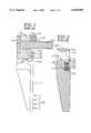
- FIG. 3is a cross-sectional view of the retainer body with integrally extending arm of the retainer of the present invention.
- FIG. 4is a front view of the retainer body with integrally extending arm shown in FIG. 3.
- FIG. 5is a cross-sectional view of a retainer whose body and arm are shown in FIG. 3.
- FIG. 6Ais a partial cross-sectional side view of the bushing incorporated in the retainer shown in FIG. 5.
- FIG. 6Bis a cross-sectional view through the slots of the bushing shown in FIG. 6A.
- FIG. 6Cis a front view of the bushing shown in FIG. 6A.
- FIG. 6Dis an end view of the bushing shown in FIG.6A.
- FIG. 7is a cross-sectional view of the cap used in the retainer shown in FIG. 5.
- a typical galley retainer shown in FIG. 1consists of body 110 and arm 112.
- a stud 114is fitted through an opening 116 in the body of the retainer.
- the studpenetrates a rotating cam 118 fitted in a machined out section 120 on the a rear face 122 of the retainer.
- the rear face of the retaineris the surface of the retainer which faces the moveable object being retained when the retainer is installed in a galley.
- Two pins 123only one of which is shown in FIG. 1, extend outwardly from the cam in a direction away from the retainer rear face.
- the retainer armserves to block and thus prevent the movement of movable objects toward the arm. Consequently, impact forces are imparted on the rear face of the arm by the moveable object as shown by arrows 124. These impact forces are substantial. They can often exceed 2300 lbs. Because a portion of the body is machined out to receive the cam, it is weakened. Consequently, cracks 126 form at the weakened body as the impact forces acting on the retainer arm attempt to bend the arm.
- an arcuate portion of the camis cutout defining two edge walls 125, only one of which is shown in FIG. 1, at either end of the cutout.
- a groove 127is formed on the back surface of the arm.
- a stop member 128is fitted into the groove and extends into the arcuate cutout on of the cam. The groove is swaged to hold the stop in place. Cam rotation is stopped when the cam edge walls 125 engage the stop member 128.
- an axial bore 131is formed in the body 130 of the retainer extending from the rear face 132 to the front face 134 of the body to accommodate a bushing (not shown) which accommodates a shaft (not shown).
- a detent mechanismis housed in a chamber 136.
- the chamberis formed by a two step process at the rear face of the retainer. First a groove 138 is machined from the rear face of the retainer arm. A spring 133 is placed in the groove on top of which is fitted a detent ball 135. Second, the groove is covered by a plate 140 which is fastened to the retainer arm with a fastener 141.
- An upper portion 142 of the bore near the rear faceis machined to a radius larger than the radius of the bore forming an arcuate path for accommodating a rotation limiting mechanism. Consequently, thickness of the upper portion 144 of the bore wall is thinned out.
- the shaft and bearingreact these impact loads on the upper portion of the bore at the rear face of the retainer. Consequently, cracks form at the thinned upper portion 144 of the wall of the bore eventually resulting in the tearing of the upper portion of the wall and the failure of the retainer.
- both of the exemplary current retainersare prone to failure due to their design.
- Another problem with current retainersis that is that the bushing or cam is not fixed in a transverse direction relative to the retainer. Thus during installation care must be taken to ensure that the cam or bushing is not separated from the retainer which may result in the loss of the ball bearings and other componentry. This make makes the installation process more difficult.
- the exemplary current retainersrequire excessive manufacturing steps.
- a retainer of the present inventioncomprises an elongated retainer arm portion 10 which is integral and extends from body portion 12 (FIGS. 3, 4 and 5).
- An axial bore 14is formed in the body for receiving a bushing (or cam) 16 and a stud 18 (FIG. 5).
- the arm and bodyare preferably formed from a single piece of material.
- the bushingcomprises a first section 15 having a diameter larger than the diameter of the axial bore and a second section 17 having diameter slightly smaller than the diameter of the axial bore (FIG. 6A).
- the bushing second endis inserted into the axial bore from the rear face 21 of the retainer (FIG. 4).
- the first sectionremains external to the axial bore.
- the bushingcontains a central bore 20.
- the stud end portion 19 extending beyond the rear face of the retaineris threaded for threading into a threaded opening formed on a galley surface during retainer to galley installation.
- the bushinghas one or two machined in place, anti-rotation pins 24 (FIGS. 6A and 6D). Each pin fits into a hole located in the galley surface to prevent the bushing from rotating with respect to the galley surface.
- Each anti-rotation pinincludes a sufficient corner radius 26 that reduces the possibility of shearing or bending in normal service.
- the bushingfurther includes a plurality of slots 28 positioned radially around the circumference of the bushing which cooperate with a ball detent 30 located within an angled bore 32 formed through the axial bore (FIGS. 3, 5, 6A and 6B).
- the ball detentcomprises a ball bearing 34 and a spring 36 positioned within the angled bore 32 which urges the ball towards the bushing as shown in FIG. 5.
- the slots 28 in the bushingallow the retainer to be rotated to various desired positions where the ball bearing engages the slots. Each slot defines a desired position.
- One or multiple slotsmay be formed depending on the number desired positions. For example, if two positions are desired, then only two slots need to be formed on the bushing.
- the relative spacing of the slotsis defined by the amount of rotation desired between each position.
- slotsother openings may be formed radially around the circumference of the bushing. Slots or other types of openings are preferred over grooves because they provide for a more positive engagement with the ball because a portion of the ball is able to penetrate entirely the slot or opening.
- the angled bore 32is formed by drilling through the axial bore lower wall 33 from the rear face 21 of the retainer.
- Some current retainersas for example the retainer shown in FIG.2, have a detent mechanism housed in a chamber formed by machining a groove machined through the rear face of the retainer, covering the groove with a plate and then fastening the plate to the retainer using a fastener.
- the present invention retainerallows for a reduction in the retainer weight by not requiring additional parts, namely the cover and fastener, and also simplifies assembly by not requiring the additional steps of forming a cover and then fastening the cover to the retainer.
- the retainer of the present inventionalso incorporates a rotation limiting mechanism.
- the rotation limiting mechanismcomprises an arcuate groove 38 formed in the retainer body at an upper portion of the axial bore 14 near the front face 22 of the retainer (FIGS. 3, 4 and 5).
- the mechanismalso includes a ball bearing 40 seated within a groove 42 formed in the end of the bushing 16 (FIGS. 5, 6A, 6C and 6D) .
- the ball bearing 40rides in the arcuate groove 36.
- the upper wall 39 of the arcuate groove 38retains the ball bearing 40 within the groove 42 preventing the ball bearing from unseating from the groove 42.
- the ball bearing 40travels along the arcuate groove. Rotation is limited, i.e., stopped, by the end walls 41 of the arcuate groove which stop the travel of the ball bearing and thus the relative rotational travel between the bushing and body (FIG. 4).
- One or multiple grooves 42may be formed radially around and at the end of the bushing (FIG. 6C) .
- the stops provide by the rotation limiting mechanismcan be changed by seating the ball bearing 40 in a different groove 42.
- the arcuate groovemay be formed at any other location around the axial bore 14 near the retainer front face.
- the end 43 of the bushingis preferably swaged for retaining the ball bearing 40 within the slot 42 and arcuate groove 36, and thereby retaining the bushing within the axial bore.
- the bushing and ball bearingsi.e., the detent mechanism ball bearing 34 and the rotation limiting mechanism ball bearing 40, are securely retained by the retainer components, thereby simplifying the installation process of the retainer to the galley, as well as eliminating the possibility of accidental disassembly of the ball detent, bushing and rotation limiter.
- An optional cap 44 having an O-ring 46 around its perimetercan be positioned in the end of the axial bore at the front face 22 of the retainer body to cover the end face 47 of the pin to minimize the trapping of dirt and other contaminants within the axial bore (FIGS. 5 and 7).
- the capis formed with a circumferential groove 45 as shown in FIG. 7.
- a circumferential groove 50may be formed on the axial bore inner surface near the front face of the retainer to accommodate the O-ring.
- the tip 70 of arm 10 of the retaineris wider than the arm and is rounded to reduce the risk of injury to the operator of the retainer or to aircraft passengers (FIG. 4).
- the tip circumferencespans, about two thirds of a circle.
- the arm and tip intersectionis defined by smooth radii 72.
Landscapes
- Engineering & Computer Science (AREA)
- Aviation & Aerospace Engineering (AREA)
- Mechanical Engineering (AREA)
- Pivots And Pivotal Connections (AREA)
- Sliding-Contact Bearings (AREA)
Abstract
Description
Claims (25)
Priority Applications (1)
| Application Number | Priority Date | Filing Date | Title |
|---|---|---|---|
| US09/290,347US6010094A (en) | 1998-04-14 | 1999-04-12 | Gallery retainer |
Applications Claiming Priority (2)
| Application Number | Priority Date | Filing Date | Title |
|---|---|---|---|
| US8174998P | 1998-04-14 | 1998-04-14 | |
| US09/290,347US6010094A (en) | 1998-04-14 | 1999-04-12 | Gallery retainer |
Publications (1)
| Publication Number | Publication Date |
|---|---|
| US6010094Atrue US6010094A (en) | 2000-01-04 |
Family
ID=22166155
Family Applications (1)
| Application Number | Title | Priority Date | Filing Date |
|---|---|---|---|
| US09/290,347Expired - Fee RelatedUS6010094A (en) | 1998-04-14 | 1999-04-12 | Gallery retainer |
Country Status (6)
| Country | Link |
|---|---|
| US (1) | US6010094A (en) |
| EP (1) | EP1073582B1 (en) |
| AU (1) | AU3554399A (en) |
| CA (1) | CA2328943C (en) |
| DE (1) | DE69940428D1 (en) |
| WO (1) | WO1999052769A1 (en) |
Cited By (14)
| Publication number | Priority date | Publication date | Assignee | Title |
|---|---|---|---|---|
| US6299153B1 (en)* | 1999-07-26 | 2001-10-09 | Discreet Industries Corporation | Wafer latch with a ball bearing assembly |
| US20040021039A1 (en)* | 2002-08-01 | 2004-02-05 | Jones Gary E. | Snap-on sidewall assembly |
| US6783299B2 (en) | 1999-07-26 | 2004-08-31 | Ovadia Meron | Latch for detachably attaching and mounting a semiconductor wafer to a support ring |
| US6802543B1 (en)* | 2002-10-25 | 2004-10-12 | Aaon, Inc. | Door handle |
| US6962024B1 (en) | 2001-07-18 | 2005-11-08 | Hughes Supply Company Of Thomasville, Inc. | Locking window having a sweep latch |
| US7063361B1 (en)* | 2002-05-30 | 2006-06-20 | Barry Gene Lawrence | Locking window |
| US20070158953A1 (en)* | 2004-10-22 | 2007-07-12 | Luke Liang | Window sash latch |
| US7665775B1 (en) | 2001-08-03 | 2010-02-23 | Hughes Supply Company Of Thomasville, Inc. | Locking window having a cam latch |
| US20110271720A1 (en)* | 2010-05-04 | 2011-11-10 | Cmech (Guangzhou) Industrial Ltd. | Novel dial-type window lock |
| US20120217342A1 (en)* | 2011-02-28 | 2012-08-30 | Airbus Operations Gmbh | Fastening arrangement for fastening a storage container in a compartment of an aircraft galley, storage container and aircraft galley |
| US20140152027A1 (en)* | 2012-11-29 | 2014-06-05 | B/E Aerospace, Inc. | Galley cart bay door latch |
| EP3333076A1 (en)* | 2016-12-12 | 2018-06-13 | Airbus Operations GmbH | Safeguarding arrangement |
| US11584528B2 (en) | 2020-09-03 | 2023-02-21 | B/E Aerospace, Inc. | Aircraft trolley retention device |
| US20240253785A1 (en)* | 2023-01-27 | 2024-08-01 | B/E Aerospace, Inc. | Retracting t divider |
Families Citing this family (4)
| Publication number | Priority date | Publication date | Assignee | Title |
|---|---|---|---|---|
| US7246718B2 (en)* | 2003-10-02 | 2007-07-24 | Zag Industries Ltd. | Toolbox with handle having cover locking mechanism |
| FR3070709B1 (en)* | 2017-09-04 | 2019-09-13 | Alstom Transport Technologies | ROTARY LATCH FOR DISTRIBUTION TROLLEY |
| EP4114785B1 (en)* | 2020-03-06 | 2025-05-21 | Oshkosh Corporation | A leak containment system for a lift and a lift with such a system |
| EP4530186A1 (en)* | 2023-09-27 | 2025-04-02 | B/E Aerospace (UK) Limited | Galley compartment retention assembly |
Citations (3)
| Publication number | Priority date | Publication date | Assignee | Title |
|---|---|---|---|---|
| US5156359A (en)* | 1991-06-13 | 1992-10-20 | The Boeing Company | Handle assembly for an aircraft door or the like |
| US5741032A (en)* | 1996-06-18 | 1998-04-21 | Reflectolite Products Company, Inc. | Sash lock |
| US5887916A (en)* | 1997-09-25 | 1999-03-30 | Kason Industries, Inc. | Safety door latch for pressurized ovens |
Family Cites Families (4)
| Publication number | Priority date | Publication date | Assignee | Title |
|---|---|---|---|---|
| GB190928255A (en)* | 1909-12-03 | 1910-05-19 | Robert William Henry Rodney | Improvements in and relating to Fasteners for Doors, Casements, or the like. |
| GB208864A (en)* | 1922-11-08 | 1924-01-03 | Charles Edward Percy Gabriel | Improvements in or relating to fasteners for ventilators, doors, windows, or the like |
| GB2297798A (en)* | 1995-02-09 | 1996-08-14 | Edward Connolly | A lever lock door or window catch arrangement |
| GB2306553B (en)* | 1995-10-31 | 2000-02-16 | C F Taylor | Catch mechanism |
- 1999
- 1999-04-12EPEP99917412Apatent/EP1073582B1/ennot_activeExpired - Lifetime
- 1999-04-12AUAU35543/99Apatent/AU3554399A/ennot_activeAbandoned
- 1999-04-12WOPCT/US1999/007938patent/WO1999052769A1/enactiveApplication Filing
- 1999-04-12CACA 2328943patent/CA2328943C/ennot_activeExpired - Fee Related
- 1999-04-12DEDE69940428Tpatent/DE69940428D1/ennot_activeExpired - Fee Related
- 1999-04-12USUS09/290,347patent/US6010094A/ennot_activeExpired - Fee Related
Patent Citations (3)
| Publication number | Priority date | Publication date | Assignee | Title |
|---|---|---|---|---|
| US5156359A (en)* | 1991-06-13 | 1992-10-20 | The Boeing Company | Handle assembly for an aircraft door or the like |
| US5741032A (en)* | 1996-06-18 | 1998-04-21 | Reflectolite Products Company, Inc. | Sash lock |
| US5887916A (en)* | 1997-09-25 | 1999-03-30 | Kason Industries, Inc. | Safety door latch for pressurized ovens |
Cited By (25)
| Publication number | Priority date | Publication date | Assignee | Title |
|---|---|---|---|---|
| US6536755B2 (en) | 1999-01-11 | 2003-03-25 | Discreet Industries Corporation | Wafer latch with a ball bearing assembly |
| US6783299B2 (en) | 1999-07-26 | 2004-08-31 | Ovadia Meron | Latch for detachably attaching and mounting a semiconductor wafer to a support ring |
| US6299153B1 (en)* | 1999-07-26 | 2001-10-09 | Discreet Industries Corporation | Wafer latch with a ball bearing assembly |
| US6962024B1 (en) | 2001-07-18 | 2005-11-08 | Hughes Supply Company Of Thomasville, Inc. | Locking window having a sweep latch |
| US7665775B1 (en) | 2001-08-03 | 2010-02-23 | Hughes Supply Company Of Thomasville, Inc. | Locking window having a cam latch |
| US7063361B1 (en)* | 2002-05-30 | 2006-06-20 | Barry Gene Lawrence | Locking window |
| US20040021039A1 (en)* | 2002-08-01 | 2004-02-05 | Jones Gary E. | Snap-on sidewall assembly |
| US6712316B2 (en)* | 2002-08-01 | 2004-03-30 | The Boeing Company | Snap-on sidewall assembly |
| US6802543B1 (en)* | 2002-10-25 | 2004-10-12 | Aaon, Inc. | Door handle |
| US8336930B2 (en)* | 2004-10-22 | 2012-12-25 | Vision Industries Group, Inc. | Window sash latch |
| US20070158953A1 (en)* | 2004-10-22 | 2007-07-12 | Luke Liang | Window sash latch |
| US20110271720A1 (en)* | 2010-05-04 | 2011-11-10 | Cmech (Guangzhou) Industrial Ltd. | Novel dial-type window lock |
| US20120217342A1 (en)* | 2011-02-28 | 2012-08-30 | Airbus Operations Gmbh | Fastening arrangement for fastening a storage container in a compartment of an aircraft galley, storage container and aircraft galley |
| US9328543B2 (en)* | 2012-11-29 | 2016-05-03 | B/E Aerospace, Inc. | Galley cart bay door latch |
| WO2014085644A1 (en)* | 2012-11-29 | 2014-06-05 | B/E Aerospace, Inc. | Galley cart bay door latch |
| CN104884348A (en)* | 2012-11-29 | 2015-09-02 | Be航天公司 | Galley cart bay door latch |
| US20140152027A1 (en)* | 2012-11-29 | 2014-06-05 | B/E Aerospace, Inc. | Galley cart bay door latch |
| US20160237723A1 (en)* | 2012-11-29 | 2016-08-18 | B/E Aerospace, Inc. | Galley cart bay door latch |
| CN104884348B (en)* | 2012-11-29 | 2016-12-21 | Be 航天公司 | Kitchen go-cart hatch door breech lock |
| US9695619B2 (en)* | 2012-11-29 | 2017-07-04 | B/E Aerospace, Inc. | Galley cart bay door latch |
| EP3333076A1 (en)* | 2016-12-12 | 2018-06-13 | Airbus Operations GmbH | Safeguarding arrangement |
| US10995529B2 (en) | 2016-12-12 | 2021-05-04 | Airbus Operations Gmbh | Safeguarding arrangement |
| US11584528B2 (en) | 2020-09-03 | 2023-02-21 | B/E Aerospace, Inc. | Aircraft trolley retention device |
| US20240253785A1 (en)* | 2023-01-27 | 2024-08-01 | B/E Aerospace, Inc. | Retracting t divider |
| US12240607B2 (en)* | 2023-01-27 | 2025-03-04 | B/E Aerospace, Inc. | Retracting T divider |
Also Published As
| Publication number | Publication date |
|---|---|
| EP1073582A4 (en) | 2004-06-23 |
| AU3554399A (en) | 1999-11-01 |
| WO1999052769A1 (en) | 1999-10-21 |
| DE69940428D1 (en) | 2009-04-02 |
| EP1073582A1 (en) | 2001-02-07 |
| CA2328943A1 (en) | 1999-10-21 |
| EP1073582B1 (en) | 2009-02-18 |
| CA2328943C (en) | 2005-01-04 |
Similar Documents
| Publication | Publication Date | Title |
|---|---|---|
| US6010094A (en) | Gallery retainer | |
| US5697727A (en) | Lock for fixing a seat of a motor vehicle to a floorpan of the vehicle | |
| JP6157518B2 (en) | Centrifuge kit and centrifuge | |
| US10526064B2 (en) | Actuating system for an actuatable door and an actuatable door having such an actuating system | |
| US5816658A (en) | Head rest lock | |
| US5871318A (en) | Quick-release track fastener | |
| US6752598B2 (en) | Device for immobilizing blades in a slot of a disk | |
| CA1098345A (en) | Safety bolt | |
| EP0300172A2 (en) | Device to prevent rotation of round cutting tool inserts | |
| US7077246B2 (en) | Fall safety device | |
| US20080042007A1 (en) | Device for securing an insert in a structure | |
| EP2455255A1 (en) | Outer hinge with a sound-dampening bearing element | |
| US5845947A (en) | Door latch lever with serviceable rod retainer | |
| EP0530132B1 (en) | Fastener with differentially inclined axes | |
| US2822014A (en) | Insert for soft materials and tang locking member therefor | |
| US4478446A (en) | Adjustable keeper assembly | |
| EP0965729B1 (en) | Locking element for turbine rotor blades | |
| GB2161210A (en) | Separable door hinge | |
| US10596933B2 (en) | Method for mounting a backrest structure of a vehicle rear seat, pivot support of a fold-over backrest structure of a vehicle rear seat | |
| US20100108796A1 (en) | Safety Belt Retractor With Variable Load Transfer In Different Function Settings | |
| RU2675140C2 (en) | Door hinge for cars | |
| EP4606706A1 (en) | Rotatable mounting system | |
| JP2002511538A (en) | Gary retainer | |
| US5687962A (en) | Bearing locking mechanism, work support | |
| EP0961884B1 (en) | Attachment bolt locking assembly |
Legal Events
| Date | Code | Title | Description |
|---|---|---|---|
| AS | Assignment | Owner name:SKYLOCK INDUSTRIES, INC., CALIFORNIA Free format text:ASSIGNMENT OF ASSIGNORS INTEREST;ASSIGNORS:CSIK, TERRENCE S.;SHORT, DALE L.;REEL/FRAME:009895/0302 Effective date:19990409 | |
| CC | Certificate of correction | ||
| REMI | Maintenance fee reminder mailed | ||
| FEPP | Fee payment procedure | Free format text:PETITION RELATED TO MAINTENANCE FEES GRANTED (ORIGINAL EVENT CODE: PMFG); ENTITY STATUS OF PATENT OWNER: SMALL ENTITY | |
| REIN | Reinstatement after maintenance fee payment confirmed | ||
| LAPS | Lapse for failure to pay maintenance fees | Free format text:PATENT EXPIRED FOR FAILURE TO PAY MAINTENANCE FEES (ORIGINAL EVENT CODE: EXP.); ENTITY STATUS OF PATENT OWNER: SMALL ENTITY | |
| FP | Lapsed due to failure to pay maintenance fee | Effective date:20030104 | |
| FPAY | Fee payment | Year of fee payment:4 | |
| PRDP | Patent reinstated due to the acceptance of a late maintenance fee | Effective date:20040528 | |
| SULP | Surcharge for late payment | ||
| FPAY | Fee payment | Year of fee payment:8 | |
| REMI | Maintenance fee reminder mailed | ||
| LAPS | Lapse for failure to pay maintenance fees | ||
| STCH | Information on status: patent discontinuation | Free format text:PATENT EXPIRED DUE TO NONPAYMENT OF MAINTENANCE FEES UNDER 37 CFR 1.362 | |
| FP | Lapsed due to failure to pay maintenance fee | Effective date:20120104 | |
| AS | Assignment | Owner name:ADHARA AEROSPACE & DEFENSE, LLC, CALIFORNIA Free format text:ASSIGNMENT OF ASSIGNORS INTEREST;ASSIGNOR:SKYLOCK INDUSTRIES;REEL/FRAME:071269/0212 Effective date:20250401 |