US6009731A - Locking device for door keeper bar - Google Patents
Locking device for door keeper barDownload PDFInfo
- Publication number
- US6009731A US6009731AUS09/080,550US8055098AUS6009731AUS 6009731 AUS6009731 AUS 6009731AUS 8055098 AUS8055098 AUS 8055098AUS 6009731 AUS6009731 AUS 6009731A
- Authority
- US
- United States
- Prior art keywords
- hasp
- shank
- wall
- housing
- aperture
- Prior art date
- Legal status (The legal status is an assumption and is not a legal conclusion. Google has not performed a legal analysis and makes no representation as to the accuracy of the status listed.)
- Expired - Fee Related
Links
- 239000002184metalSubstances0.000claimsdescription7
- 229910052751metalInorganic materials0.000claimsdescription7
- 230000000295complement effectEffects0.000claimsdescription2
- 229910000831SteelInorganic materials0.000abstractdescription13
- 239000010959steelSubstances0.000abstractdescription13
- 230000001681protective effectEffects0.000description4
- 230000001012protectorEffects0.000description4
- 229910001018Cast ironInorganic materials0.000description2
- 239000000463materialSubstances0.000description2
- 230000000737periodic effectEffects0.000description2
- 229910000746Structural steelInorganic materials0.000description1
- 230000006835compressionEffects0.000description1
- 238000007906compressionMethods0.000description1
- 230000006378damageEffects0.000description1
- 238000006073displacement reactionMethods0.000description1
- 230000001747exhibiting effectEffects0.000description1
- 238000009434installationMethods0.000description1
- 230000013011matingEffects0.000description1
- 238000012986modificationMethods0.000description1
- 230000004048modificationEffects0.000description1
- 239000007787solidSubstances0.000description1
Images


Classifications
- E—FIXED CONSTRUCTIONS
- E05—LOCKS; KEYS; WINDOW OR DOOR FITTINGS; SAFES
- E05B—LOCKS; ACCESSORIES THEREFOR; HANDCUFFS
- E05B39/00—Locks giving indication of authorised or unauthorised unlocking
- E—FIXED CONSTRUCTIONS
- E05—LOCKS; KEYS; WINDOW OR DOOR FITTINGS; SAFES
- E05B—LOCKS; ACCESSORIES THEREFOR; HANDCUFFS
- E05B13/00—Devices preventing the key or the handle or both from being used
- E05B13/002—Devices preventing the key or the handle or both from being used locking the handle
- E—FIXED CONSTRUCTIONS
- E05—LOCKS; KEYS; WINDOW OR DOOR FITTINGS; SAFES
- E05B—LOCKS; ACCESSORIES THEREFOR; HANDCUFFS
- E05B67/00—Padlocks; Details thereof
- E05B67/38—Auxiliary or protective devices
- Y—GENERAL TAGGING OF NEW TECHNOLOGICAL DEVELOPMENTS; GENERAL TAGGING OF CROSS-SECTIONAL TECHNOLOGIES SPANNING OVER SEVERAL SECTIONS OF THE IPC; TECHNICAL SUBJECTS COVERED BY FORMER USPC CROSS-REFERENCE ART COLLECTIONS [XRACs] AND DIGESTS
- Y10—TECHNICAL SUBJECTS COVERED BY FORMER USPC
- Y10S—TECHNICAL SUBJECTS COVERED BY FORMER USPC CROSS-REFERENCE ART COLLECTIONS [XRACs] AND DIGESTS
- Y10S292/00—Closure fasteners
- Y10S292/32—Freight car door fasteners
- Y—GENERAL TAGGING OF NEW TECHNOLOGICAL DEVELOPMENTS; GENERAL TAGGING OF CROSS-SECTIONAL TECHNOLOGIES SPANNING OVER SEVERAL SECTIONS OF THE IPC; TECHNICAL SUBJECTS COVERED BY FORMER USPC CROSS-REFERENCE ART COLLECTIONS [XRACs] AND DIGESTS
- Y10—TECHNICAL SUBJECTS COVERED BY FORMER USPC
- Y10S—TECHNICAL SUBJECTS COVERED BY FORMER USPC CROSS-REFERENCE ART COLLECTIONS [XRACs] AND DIGESTS
- Y10S70/00—Locks
- Y10S70/43—Lock protectors
- Y—GENERAL TAGGING OF NEW TECHNOLOGICAL DEVELOPMENTS; GENERAL TAGGING OF CROSS-SECTIONAL TECHNOLOGIES SPANNING OVER SEVERAL SECTIONS OF THE IPC; TECHNICAL SUBJECTS COVERED BY FORMER USPC CROSS-REFERENCE ART COLLECTIONS [XRACs] AND DIGESTS
- Y10—TECHNICAL SUBJECTS COVERED BY FORMER USPC
- Y10S—TECHNICAL SUBJECTS COVERED BY FORMER USPC CROSS-REFERENCE ART COLLECTIONS [XRACs] AND DIGESTS
- Y10S70/00—Locks
- Y10S70/56—Lock protecting cover
- Y—GENERAL TAGGING OF NEW TECHNOLOGICAL DEVELOPMENTS; GENERAL TAGGING OF CROSS-SECTIONAL TECHNOLOGIES SPANNING OVER SEVERAL SECTIONS OF THE IPC; TECHNICAL SUBJECTS COVERED BY FORMER USPC CROSS-REFERENCE ART COLLECTIONS [XRACs] AND DIGESTS
- Y10—TECHNICAL SUBJECTS COVERED BY FORMER USPC
- Y10T—TECHNICAL SUBJECTS COVERED BY FORMER US CLASSIFICATION
- Y10T292/00—Closure fasteners
- Y10T292/08—Bolts
- Y10T292/096—Sliding
- Y10T292/1014—Operating means
- Y10T292/1022—Rigid
- Y10T292/1025—Padlock or seal catch
- Y—GENERAL TAGGING OF NEW TECHNOLOGICAL DEVELOPMENTS; GENERAL TAGGING OF CROSS-SECTIONAL TECHNOLOGIES SPANNING OVER SEVERAL SECTIONS OF THE IPC; TECHNICAL SUBJECTS COVERED BY FORMER USPC CROSS-REFERENCE ART COLLECTIONS [XRACs] AND DIGESTS
- Y10—TECHNICAL SUBJECTS COVERED BY FORMER USPC
- Y10T—TECHNICAL SUBJECTS COVERED BY FORMER US CLASSIFICATION
- Y10T292/00—Closure fasteners
- Y10T292/08—Bolts
- Y10T292/1043—Swinging
- Y10T292/1075—Operating means
- Y10T292/1083—Rigid
- Y10T292/1086—Padlock or seal catch
- Y—GENERAL TAGGING OF NEW TECHNOLOGICAL DEVELOPMENTS; GENERAL TAGGING OF CROSS-SECTIONAL TECHNOLOGIES SPANNING OVER SEVERAL SECTIONS OF THE IPC; TECHNICAL SUBJECTS COVERED BY FORMER USPC CROSS-REFERENCE ART COLLECTIONS [XRACs] AND DIGESTS
- Y10—TECHNICAL SUBJECTS COVERED BY FORMER USPC
- Y10T—TECHNICAL SUBJECTS COVERED BY FORMER US CLASSIFICATION
- Y10T292/00—Closure fasteners
- Y10T292/31—Hasps
- Y10T292/331—Seal catch
- Y—GENERAL TAGGING OF NEW TECHNOLOGICAL DEVELOPMENTS; GENERAL TAGGING OF CROSS-SECTIONAL TECHNOLOGIES SPANNING OVER SEVERAL SECTIONS OF THE IPC; TECHNICAL SUBJECTS COVERED BY FORMER USPC CROSS-REFERENCE ART COLLECTIONS [XRACs] AND DIGESTS
- Y10—TECHNICAL SUBJECTS COVERED BY FORMER USPC
- Y10T—TECHNICAL SUBJECTS COVERED BY FORMER US CLASSIFICATION
- Y10T292/00—Closure fasteners
- Y10T292/51—Seal bolts
- Y—GENERAL TAGGING OF NEW TECHNOLOGICAL DEVELOPMENTS; GENERAL TAGGING OF CROSS-SECTIONAL TECHNOLOGIES SPANNING OVER SEVERAL SECTIONS OF THE IPC; TECHNICAL SUBJECTS COVERED BY FORMER USPC CROSS-REFERENCE ART COLLECTIONS [XRACs] AND DIGESTS
- Y10—TECHNICAL SUBJECTS COVERED BY FORMER USPC
- Y10T—TECHNICAL SUBJECTS COVERED BY FORMER US CLASSIFICATION
- Y10T70/00—Locks
- Y10T70/30—Hasp
- Y—GENERAL TAGGING OF NEW TECHNOLOGICAL DEVELOPMENTS; GENERAL TAGGING OF CROSS-SECTIONAL TECHNOLOGIES SPANNING OVER SEVERAL SECTIONS OF THE IPC; TECHNICAL SUBJECTS COVERED BY FORMER USPC CROSS-REFERENCE ART COLLECTIONS [XRACs] AND DIGESTS
- Y10—TECHNICAL SUBJECTS COVERED BY FORMER USPC
- Y10T—TECHNICAL SUBJECTS COVERED BY FORMER US CLASSIFICATION
- Y10T70/00—Locks
- Y10T70/40—Portable
- Y10T70/413—Padlocks
- Y10T70/487—Parts, accessories, attachments and adjuncts
- Y10T70/493—Protectors
- Y10T70/498—Shields or canopies
- Y—GENERAL TAGGING OF NEW TECHNOLOGICAL DEVELOPMENTS; GENERAL TAGGING OF CROSS-SECTIONAL TECHNOLOGIES SPANNING OVER SEVERAL SECTIONS OF THE IPC; TECHNICAL SUBJECTS COVERED BY FORMER USPC CROSS-REFERENCE ART COLLECTIONS [XRACs] AND DIGESTS
- Y10—TECHNICAL SUBJECTS COVERED BY FORMER USPC
- Y10T—TECHNICAL SUBJECTS COVERED BY FORMER US CLASSIFICATION
- Y10T70/00—Locks
- Y10T70/50—Special application
- Y10T70/5611—For control and machine elements
- Y10T70/5757—Handle, handwheel or knob
- Y10T70/5765—Rotary or swinging
- Y10T70/577—Locked stationary
- Y10T70/5774—Externally mounted locking device
- Y10T70/5779—With padlock
- Y—GENERAL TAGGING OF NEW TECHNOLOGICAL DEVELOPMENTS; GENERAL TAGGING OF CROSS-SECTIONAL TECHNOLOGIES SPANNING OVER SEVERAL SECTIONS OF THE IPC; TECHNICAL SUBJECTS COVERED BY FORMER USPC CROSS-REFERENCE ART COLLECTIONS [XRACs] AND DIGESTS
- Y10—TECHNICAL SUBJECTS COVERED BY FORMER USPC
- Y10T—TECHNICAL SUBJECTS COVERED BY FORMER US CLASSIFICATION
- Y10T70/00—Locks
- Y10T70/70—Operating mechanism
- Y10T70/7441—Key
- Y10T70/7915—Tampering prevention or attack defeating
- Y10T70/7921—Armoring
Definitions
- This inventionrelates to bolt seal locking devices, and more particularly, to devices including seal protectors for use with bolt seals for locking door keeper bars.
- Cargo shipping vehicles and containersare subject to widespread tampering due to the value of the cargo.
- Thievesbreak open conventional bolt seals which comprise a steel bolt shank to which a head is swaged at one end and to which a locking body containing a lock mechanism is locked at the other end.
- the shanksare subject to relatively easy tampering by way of bolt cutters or cutting torches.
- the problemis aggravated by the fact that different rail cars, trucks and cargo containers, for example, may employ different types of latches and hasps.
- a latch assembly 220comprises a keeper bar 222 which is secured to a door 224 by clamps (not shown) for manual rotation about its longitudinal axis 226.
- the bar 222 in the one angular position shownis in a door locked state.
- the bar 222 ends (not shown)disengage a locking arrangement (not shown) permitting the door to swing open in a known manner.
- a handle assembly 230is secured to the bar to facilitate rotation of the bar.
- Assembly 230includes a handle 232 pivoted at pin 233 to link 234 welded to the bar 222.
- a hasp 236, a wire loop,is secured to a plate 238 which is fastened to the door 224 by rivets 240 or bolts.
- a second wire loop hasp 236'is secured to the handle 232 which has an opening through which the hasp 236 passes juxtaposed with hasp 236'.
- a padlock or seal bolt(not shown) is passed through the loops of the two hasps to lock the handle in the position shown. The locked handle prevents it and thus the keeper bar from being rotated to the bar opened unlocked state.
- the rivets holding the plate 238, the padlock or bolt seal, or the haspsare all exposed for tampering to unlock the handle and permit the keeper bar 222 to be rotated open.
- seal protectorsare available to further protect the seals from tampering access.
- U.S. Pat. No. 5,413,393illustrates a bolt seal and a tool for breaking the shank at the head end of the shank.
- the toolengages the head and manually bends the shank which breaks due to serrations in the shank.
- a locking sealemploys a steel bolt with a head at one end and grooves along the bolt shank for use with a locking body containing a releasable locking mechanism which engages the grooves. The mechanism is released by a disclosed mating specially designed tool and which locking body mechanism is otherwise difficult to release and is relatively tamper resistant.
- U.S. Pat. No. 5,347,689shows a further bolt seal configuration using a bolt and locking body and which requires a tool similar to the tool of the '393 patent tool to break the seal shank.
- Other sealsare known wherein tool cutters are required to cut the bolt shank.
- a container hasp protectoris disclosed.
- a metal box-like bodyhas a top plate, a bottom plate, right and left side plates, an open rear face and a front face.
- a shield plateis on the front face and extends between the side plates forming a top opening in the face between the shield plate and top plate and a bottom opening in the face between the shield plate and the bottom plate. The body is arranged to protect the hasp from intentional breakage.
- the shield platehas an aperture which cooperates with aligned apertures in a hasp to receive a breakaway security seal.
- the present inventorsrecognize that potential thieves do not like to tamper with locks that are difficult to open, especially locks on cargo doors which may be subject to periodic surveillance. If the locks can not be opened in a few minutes, thieves are likely to pass up such tampering. For this reason the device of the '149 patent is believed not desirable for valuable cargo containers and the like.
- U.S. Pat. No. 3,951,443discloses a security lock that employs a locking pin.
- the lockemploys interengaged keepers with aligned through apertures which receive the pin.
- One of the keepershas a through pilot hole in the face thereof so that the pin can be cut apart with a heavy duty power drill for use by an authorized person.
- the only way for the lock to be openedis by destroying the pin. This is not satisfactory because the locking pin is destroyed rather than capable of reuse. More importantly, it is disclosed that thieves would not like to use a noisy, inconvenient and conspicuous power drill. However, portable cutting torches may also be used to cut the pin via the pilot hole. This is believed unsatisfactory.
- Padlock protector devicesare disclosed in U.S. Pat. Nos. 4,898,008, 4,033,155, 5,146,771, and 5,477,710. These also are not satisfactory for cargo shipping containers or rail cars because the shackles are readily exposed for destruction by a tamperer. Further these devices are not disclosed as operative with bolt seals of the type described above.
- the present inventorsrecognize a need for a cost effective seal and latch protection device which uses cost effective reusable locking bodies or reusable bolts and locking bodies for use with keeper bars. They recognize a need for a protection device which precludes access to the bolt shank which is vulnerable to tampering while at the same time locking a door keeper bar more securely than present latch locking devices.
- a locking deviceis for use with a rotating keeper bar for an enclosure door and a locking seal, the keeper bar for rotation to door open and locked states, the seal comprising a shank having opposing ends with locking means at one shank end and a locking body selectively locked to the shank at the opposing shank end.
- the devicecomprises a hasp having at least one seal shank receiving aperture, the hasp for being fixedly secured to and for rotation with the keeper bar to the open and closed states and a housing having a plurality of walls defining a cavity, a first housing wall having an opening for releaseably receiving the hasp and keeper bar in the cavity.
- At least one second housing wallhas an aperture juxtaposed with the received hasp at least one aperture for receiving the shank therethrough.
- the seal locking means and lock bodylocking the received hasp to the housing at least one second wall.
- the housingincludes means cooperating with the door for precluding rotation of the keeper bar in the seal locked state.
- the housing and haspin one aspect include means arranged so that the shank and hasp in the cavity between the locking head and the locking body are substantially enclosed to preclude access to the shank by tampering tools.
- the cavityis dimensioned to permit the hasp to rotate within the cavity as the keeper bar is rotated in the unlocked state.
- the haspis metal and the keeper bar is an elongated rod, the hasp for weld attachment to the keeper bar.
- the housing at least one second wallin a further aspect comprises juxtaposed plate members forming housing top and bottom walls, the plate members each having a shank receiving aperture aligned with the received at least one hasp aperture.
- the locking meansmay comprise a head secured to the shank, the housing including a further plate member in the cavity intermediate the housing top and bottom walls, the further plate member having a further aperture for receiving the shank therethrough aligned with the juxtaposed top and bottom wall apertures, the top wall aperture being enlarged relative to the further aperture for receiving the head therethrough so that the received head is in the cavity intermediate the top wall and further plate member.
- the locking bodyin a further aspect includes a tapered portion, the bottom wall aperture being enlarged relative to the shank to receive and engage the tapered portion.
- the further aperturepreferably has a tapered portion, the head including a tapered portion for engaging the aperture tapered portion.
- the housing plurality of wallsinclude opposing side walls, a rear wall and a front wall secured to the at least one second wall, the at least one second wall comprising a bottom wall, a top wall and an intermediate wall between the top and bottom walls, the opening for the hasp being in the rear wall, the bottom, top and intermediate walls all having an aperture for receiving the shank.
- meansare provided for fixedly securing the housing to the door with the hasp received in the cavity.
- the locking means head and the top walleach having complementary tapered surfaces.
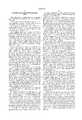
- FIG. 1is an isometric view of a bi-level and tri-level automobile rail car latch and hasp assembly
- FIG. 2is a partially in section isometric view of the latch of FIG. 1 assembled with a seal and hasp protection device according to one embodiment of the present invention without a locking bolt seal;
- FIG. 3is an isometric view partially in section showing in greater detail the protection device of FIG. 2 without the latch;
- FIG. 4is a side elevation sectional view of the device of FIG. 2 attached to the latch hasp of FIG. 1 with a locking bolt seal attached to the bolt shank and hasp in the locked mode;
- FIG. 5is a side elevation view partially in section similar to FIG. 4 and partially fragmented showing a tool in place for releasing the locking body from the shank of the locking bolt of the device of FIG. 4;
- FIG. 6is a partially in section isometric view of a protection device according to a second embodiment of the present invents for use with the latch of FIG. 1;
- FIG. 7is a side elevation sectional view of the device of FIG. 6 with a bolt seal and without a latch attached;
- FIG. 8is a side elevation sectional view of the device of FIG. 7 attached to the latch hasp of FIG. 1;
- FIG. 9is an isometric view of a latch and hasp assembly employed with box rail cars sliding doors including a bolt shank in place for use with the protection device according to a third embodiment of the present invention.
- FIG. 10is an isometric view of a component used on the latch assembly of FIG. 9;
- FIG. 11is a side elevation view of a further component of the latch assembly of FIG. 9;
- FIG. 12is a partially in section isometric view of a protection device according to a third embodiment of the present invention for use with the latch of FIG. 9;
- FIG. 13is a side elevation view partially in section of the protection device of FIG. 12.
- FIG. 14is a side elevation sectional view of the device of FIG. 12 attached to the latch hasp of FIG. 9 in the locked mode with a locking bolt seal in place;
- FIG. 15is an isometric view of a prior art door and keeper bar latch assembly
- FIGS. 16a, 16b and 16care respective front elevation, side elevation and top plan sectional views of the keeper bar of FIG. 15 with a hasp attached according to a fourth embodiment of the present invention, FIG. 16c being taken along lines 16c--16c of FIG. 16a;
- FIG. 17is a top plan view partially in section of a device according to the fourth embodiment of the present invention.
- FIG. 18is a front elevation view partially in section of the embodiment of FIG. 17;
- FIG. 19is a sectional plan view of the embodiment of FIG. 18 taken alone lines 19--19;
- FIG. 20is a sectional front elevation view of the embodiment of FIG. 17 taken along lines 20--20 illustrating an attached bolt seal in phantom;
- FIG. 21is an isometric sectional view of the device of FIG. 17.
- FIG. 22is a side sectional elevation view of the device of FIG. 18 taken along lines 22--22.
- latch 2is a conventional existing assembly for securing two opposing doors of automobile carrying rail cars which may be bi-level or tri-level.
- Latch 2comprises a sheet metal plate member 4 secured to one rail car door (not shown) and a staple 6 secured to the plate member 4.
- An elongated sheet metal latch member 8has a hole through which is loosely attached staple 6 and has a slot 10 at the end distal the staple 6.
- a second sheet metal plate member 12is secured to the other rail car door (not shown).
- a hasp assembly 14comprises a first L-shaped hasp 16 having a leg 18 with an aperture 20. Hasp 16 pivots at pin 22 in directions 24.
- a second L-shaped hasp 26is fixed to plate member 12.
- Hasp 26 leg 32has an aperture 28 alignable with the aperture 20 of movable hasp 14.
- Legs 18, 30 and 32form a channel which receives the member 8 adjacent to the slot 10, hasp 26 passing through the slot 10.
- the member 8is movable in directions 34 and 36 to engage and disengage the hasp 26 after the hasp 16 is rotated in directions 24.
- Seal protection device 38comprises a box-like casing or housing 40 preferably fabricated of 5/16 inch thick sheet steel plate members preferably welded together. While discrete plate members are shown, curved or rounded walls without discrete boundaries may also be used.
- the housing 40has a front plate member wall 42, a rear plate member wall 44, and two opposing lateral side plate member walls 46, 48.
- the wallsmay be formed of a single sheet bent as shown and, then preferably, butt welded medially side wall 46.
- the walls 40, 42, 44 and 46define a cavity 50 having a plurality of sides, a top and a bottom. The cavity top is enclosed with a top plate member wall 52 and the cavity bottom is enclosed with a bottom plate member wall 54.
- An intermediate wall 56is in the cavity 50 dividing the cavity 50 into two subchambers.
- the walls 52, 54 and 56are preferably welded to the casing 40.
- the top wall 52has a circular hole 58 next adjacent to wall 44.
- the bottom wall 54has a circular hole 60.
- Wall 56has a circular hole 62 which has a beveled edge 64.
- the holes 58, 60 and 62are preferably axially aligned.
- Wall 54has a rear section 66 and a front section 68.
- the rear section 66is normal to all of the casing 40 walls.
- the front section 68is normal to the side walls but inclined relative to the rear and front walls as best seen in FIG. 4.
- the rear wall 44depends beyond the bottom wall 54 as do side walls 46 and 48.
- the depending portionsare coextensive with and abut bottom wall rear section 66.
- the depending portionsform a protective region about the bolt seal 70, and in particular, about the locking body 72 containing the locking mechanism (not shown).
- a depending side wall 48'has a hole 74 for receiving a tamper evidencing seal (not shown).
- the seal 70is preferably releasable as more fully described in the aforementioned copending application incorporated by reference herein.
- the sealmay be of other configurations which may be commercially available or of the type described in the commonly owned patents described in the introductory portion.
- the seal 70preferably comprises a circular steel shank 76 to which is swaged a locking head 78 having a frusto-conical portion tapering toward the shank 76.
- the frusto-conical portionmates with and nests within and against the beveled edge 64 of hole 62 in the intermediate wall 56.
- the head 78has a diameter smaller than the top wall 52 hole 58 to pass therethrough.
- the head 78is located in the chamber defined by walls 52 and 56.
- the shank 76 adjacent the other endhas an axial array of annular grooves 80 which mate with the locking mechanism (not shown) of locking body 72, which mechanism is fully described in the aforementioned copending application.
- the shank 76has an aperture 77 therethrough for receiving a tamper indicating seal (not shown) which is engaged also with hole 74.
- the locking body 72is formed of a steel casing which may be hardened to resist tampering and has a tapered outer surface.
- the smaller end of the casingis smaller than the hole 60 of bottom wall 54 so as to partially engage this hole to preclude tampering with the shank whose exposed portion between the head 78 and locking body 72 is entirely within cavity 50 between the walls 56 and 54.
- the locking body mechanismhas jaws (not shown) that are releasably engaged with any of the shank grooves 80. This permits the locking body 70 to enter into the hole 60 in the locked state.
- the locking jawspermit the body 70 to slide along the shank toward the head 78 while locked against displacement in the opposite direction unless released.
- Rear wall 44has a substantially square opening 82 except for an enlarged transverse region 84.
- the opening 82receives the hasp 26 (FIG. 2) and the enlarged region 84 receives the leg 18 of the hasp 16 as best seen in FIG. 4. There may be some clearance therebetween.
- the received hasp apertures 20 and 28are aligned with the holes 58, 60 and 62 of the device 38.
- the bolt seal 70 shankis passed through all of the aligned apertures, with the head nested in hole 62.
- the locking body 72is then attached to the shank until it seats in the hole 60 and against the bottom wall 54.
- the latch haspsenclose the opening 82 in the rear wall and support the device 38.
- the shank 76 between the head 78 and seal locking body 72is fully enclosed and inaccessible by tampering tools external the casing 40.
- a tool 86As more fully described in the aforementioned U.S. Pat. No. 5,732,989, is employed.
- the tool 86has a pair of squeezable handles 88, 90.
- a jaw 92is secured to handle 90.
- a second jaw 94is pivotally secured to handle 88 via link 96.
- a compression spring 98is between the jaws.
- a cylinder 100is pivotally attached to jaw 92.
- the cylinder 100engages the locking body 72 internal locking mechanism employing a spring.
- This spring(not shown) has a high spring constant, e.g., requiring several hundred pounds force to displace. This spring keeps the locking body jaw mechanism locked.
- the tool 86by manually squeezing the handles together exerts a highly leveraged force against the jaw mechanism spring to displace and unlock these jaws.
- the locking mechanism springis relatively tamper resistant due to its high spring load.
- the depending side wall portions such as portion 48'preclude bolt cutters from accessing the exposed locking body.
- the recessed head 78is also not accessible to bolt cutters. Further, cutting torches will most likely melt and fuse the head or locking body to the casing and at best will take considerable time to free the latch of the device 38. Such increased tampering time serves as a deterrent to thieves who disdain lengthy tampering due to potential periodic surveillance.
- the inclination of bottom wall section 68provides clearance access for the tool 86. The tool 86 can access the locking body 72 through the open one side of the casing 40 at the depending walls 48' which preclude easy access by more conventional tools.
- FIGS. 6, 7 and 8illustrate a second embodiment comprising a protection device 102 having a housing 104 for use with a breakaway seal 106 of the type disclosed in the aforementioned U.S. Pat. Nos. 5,347,689 and 5,413,393.
- Housing 104is made of sheet steel plate members similar to the housing 40 of FIG. 3, and is used with the latch 2, FIG. 1.
- the housing 104has a front wall 107, a rear wall 108 and opposing lateral side walls 110 and 112.
- the rear wall 108has an opening 114 identical to the opening 82 and a region 115 identical to region 84 of the housing 40, FIG. 2, for receiving the hasps 16 and 26.
- top wall 116encloses cavity 118 at the top thereof.
- Top wall 116has a hole 119 with a beveled edge 120.
- the edge 120mates with and engages the received frusto-conical portion of seal 106 head 124.
- the seal 106 shank 126is partially surrounded by top wall 116 with no portion exposed above the top wall 116.
- Bottom wall 128is formed of a right angle iron.
- the apex 130 of the wall 128is interior the space between the front, rear and side walls closest to the top wall 116.
- the bottom wall 128has two inclined sections 132 and 134 each secured to and terminating distal the apex 130 at a different respective side wall 110, 112.
- a lock body 136 on the seal 106is partially received in a hole 138 in the bottom wall through the apex 130 and is adjacent to the rear wall 108.
- the walls being sheet steelare preferably joined by welds.
- the bolt seal lock body 136includes a locking collet (not shown) that slides up the seal 106 shank 126 in a one way clutch action.
- the colletengages the grooves 140 in locking engagement as described in the aforementioned patents '689 and '393. This permits a portion of the lock body casing to enter into the cavity 118 so that the shank 126 is located fully within the cavity.
- the bottom wall 128forms a V-shaped recess with the front and rear walls which surround the locking body. This precludes accessing the body 136 from the sides with tampering tools. The access is only from the bottom direction which makes it more difficult to tamper with the locking body 136.
- the head 124is protected and shielded on three sides by upwardly extending respective portions 107', 110' and 112' of the front wall 107, and side walls 110 and 112.
- the front wall portion 107' and side wall portion 110'extend for their entire transverse extent beyond the top wall 116, FIG. 6.
- the side wall portion 112'extends upwardly beyond the top wall slightly less than one half of the wall 112 width from the rear to front wall to form an open region 140 above top wall 116 at the housing side.
- the open region above top wall 116 and the opening 114 in the rear wall 108is shielded by the latch 2 (FIG. 1) which precludes access to the head 124 from the rear of device 102.
- the only side access to the headis via the open region 140 to permit use of the seal breaking tool (not shown). Tampering tool access to the head is minimized by the upward extending portions 107', 110' and 112' and to the lock body 136 by the surrounding bottom and side walls. Torch access to the head and lock body requires undesirable excessive time to defeat the locked seal.
- FIGS. 12-14A third embodiment of a bolt seal protective device 142 is shown in FIGS. 12-14 for use with a rail box car latch 144, FIGS. 9-11.
- the latch 144is used on sliding doors of box cars.
- the latch 144comprises a yoke member 146 which typically is cast iron as are all of the components of the latch 144.
- the yoke member 146comprises a pair of yokes 148, 150 secured by a common plate member 152.
- a handle 154is pivoted to yoke 148 by pin 156.
- a stud 157 with an enlarged head 159upstands from a side of the handle 154.
- a wedge hasp 158 locking member 160is pivoted to yoke 150 by pin 162.
- locking member 160comprises a body 164 pinned by pin 162 via hole 163, an upstanding L-shaped rib 166 and a tongue 168.
- a tamper indicating seal (not shown) receiving hole 170is in rib 166.
- the rib 166 and hole 170are adjacent to the handle 154 when the wedge hasp 158 is in the locked state of FIG. 9.
- the wedge hasp 158tapers somewhat to end 172, which end forms a hasp.
- the end 172has a hole 174 for receiving a locking bolt 176 of the present invention, or as in the prior art, for receiving the shackle of a padlock (not shown) or a conventional bolt seal shank of the representative type shown in the '393 patent, for example.
- the hasp 158is passed through the yokes 148 and 150 in the locking state. In this locked state, the locking member 160 is pivoted to the position shown in FIG. 9 with the tongue 168 engaged with a recess (not shown) in a side of the wedge hasp 158.
- the locking member 160is pivoted in direction 161 about pin 162 to disengage tongue 168 from the wedge hasp recess.
- the wedge hasp 158is then free to be disengaged from the yokes 148 and 150 in direction 163. All of the above described structure of the latch 144 is secured to the side of a box car stationary wall.
- a sliding door securing bar 178is cast iron and elongated.
- the bar 178has an aperture 180 at one end for receiving a staple 182 secured to the box car door (not shown), the staple movably locking the bar 178 to the door.
- the bar 178has a somewhat centrally located enlarged portion 183 with a rectangular opening 184 which receives therethrough the wedge hasp 158, FIG. 9, in the locked state.
- the end of the bar 178 distal staple 182has an aperture 186 for receiving the stud 157.
- the handle 154has a seal receiving opening (not shown) to receive the tamper indicating seal which is engaged with the hole 170 of the locking member 160 in the locked state.
- Prior art bolt seals locked to the hasp hole 174are easily defeated by thieves because the shanks are exposed for breakage.
- the handle 154pivots about pin 156 to cam the door shut with the locking member 160 in the unlocked state.
- the locking member 160is then pivoted to the locking state of FIG. 9.
- the protection device 142employs bolt 176, which has a 180° bight 177, FIG. 14. The bight 177 sits within the hole 174 of the wedge hasp 158 (FIG. 9).
- the bolt 176has a short shank portion 188 and a long shank portion 190.
- the long portion 190has an axial array of circular grooves 192 the same as grooves 80 in shank 76 (FIG. 4). These grooves are for releasable locking engagement with locking body 72 described above and in U.S. Pat. No. '989.
- the protection device 142comprises a sheet metal housing 143, preferably steel, including a front plate member wall 192, a rear plate member wall 194 and two opposing lateral side walls 196, 198. These walls form a cavity 197 having four sides, a top and a bottom.
- the side wall 198has a notch 200.
- the front wall 192has a top portion 202 that extends toward the top of the device 142 higher than the side and rear walls.
- the cavity 197 bottomis enclosed by bottom wall 204.
- Bottom wall 204is formed with a rear plate member section 206 normal to all of the walls and a front plate member section 208 normal to the side walls and inclined to the front and rear walls.
- the rear section 206has an aperture 210 for receiving a portion of the locking body 72 and the bolt 176 long bolt portion 190.
- the front section 208has an aperture 212 for receiving the bolt 176 short portion 188.
- the rear and side wallsdepend below the bottom wall 204 to form a U-shaped protective region for the locking body 72. A portion of the locking body 72 enters and engages the aperture 210 in the locked state.
- the bolt 176is first inserted in the wedge hasp hole 174 as shown in FIG. 9 after the latch 144 is placed in the locked state of FIG. 9.
- the device 142 cavity 197is open at the top for receiving the latch 144 wedge hasp 158.
- the yoke 148abuts the upper portion 202 of the front wall and overlies and encloses the open top of the cavity 197, FIG. 14.
- the yoke 148has a leg 148' (FIG. 9) which engages and encloses the notch 200.
- a cable(not shown) is engaged with holes 214 and 215 in respective side wall 198 and front wall 192, FIGS. 12 and 13.
- the cableattaches the device 142 to a rail car.
- Hole 216, FIG. 14, in the shank of the bolt 176receives a tamper indicating seal (not shown).
- the latch 144fully encloses the bolt 176 in the region at the bight 177 to the locking body 72, precluding tampering access to the bolt to break the bolt open. While the bolt shank portion 188 is exposed through the bottom wall 204, this portion is harmless with respect to breaking the bolt 176 by tampering.
- the bolt locking means in the claimscorresponds to the bight 186 in this embodiment as compared to the bolt heads 78 and 124 in the other embodiments described hereinabove.
- the bolt locking meansis enclosed to preclude tampering.
- the bolt locking meansi.e., the bight
- the bolt head locking meansis partially enclosed due to the presence of hole 58. Tests on rail cars exhibiting 10% breaking and entering with prior art bolt seals exhibited no breakage of the seals on rail cars sealed with the device 142.
- device 242comprises a seal protective casing 244 and a hasp 246 which is preferably welded to keeper bar 222.
- hasp 246is preferably steel sheet material and U-shaped.
- Hasp 246comprises a transverse base member 248 and two spaced parallel legs 250, 252. The legs 250, 252 are welded at their edges distal the member 248 to the keeper bar 222 with the plane of the legs parallel to the keeper bar longitudinal axis 226.
- the plane of the base member 248is also parallel to the keeper bar axis.
- a seal shank 126 (FIG. 8) receiving aperture 254is in leg 252 and a preferably identical seal shank receiving aperture 256 is in leg 250 aligned with aperture 254.
- the hasp 246, FIG. 16chas a width w of about the same as or slightly greater than the diameter of the keeper bar 222 which is a circular cylindrical rod-like member. While the hasp 246 is shown with two legs, more or fewer legs may be employed according to a given implementation. For example, the hasp may comprise a solid single flat plate (not shown) welded at an edge to the keeper bar with the hasp plane parallel to the bar axis. The hasp 246 is thus permanently attached to the keeper bar 222.
- Casing 244comprises steel plates welded together to form a housing 258 from which a U-shaped lock body shield 260 extends.
- the housing 258has a front wall 262, a pair of opposing first and second respective side walls 264 and 266, a top wall 268, a bottom wall 270 and a rear wall 272.
- the housing 258has a cavity 274 formed by the side, top and bottom walls.
- the top wall 268has a U-shaped recess 276, FIG. 17. A similar recess is in the bottom wall. These recesses receive the keeper bar as shown in the figures so that the keeper bar is generally flush with the rear wall 272 outer surface or recessed into the cavity 274 somewhat relative to the rear wall 272, FIG. 19.
- An intermediate steel plate internal wall 278, FIGS. 19 and 20,is in the cavity 274 and is welded at its edges to the top, bottom, front and rear walls dividing chamber 274 into subchambers and forming a secondary chamber 280 in chamber 274.
- Side wall 264has a seal head 78 receiving aperture 282 through which the seal head 78 passes into chamber 280, FIG. 20.
- Side wall 266has a locking body 72 receiving aperture 284 in which the body is partially received. Apertures 282 and 284 function similar to the holes 58 and 60, respectively, of the FIG. 3 embodiment.
- Intermediate wall 278has an aperture 286 having a beveled edge for receiving the tapered portion of the seal head 78, FIG. 20.
- the lock body 72 shield 260comprises walls 288, 290 and 292.
- a bolt 294, FIG. 19,extends through a corresponding opening in the rear wall 272 and in the shield wall 288.
- the bolts 294are attached to the door 224 by nuts 296 or, in the alternative, the bolts may be omitted and the casing 244 need not be attached to the door.
- the casing 244may be welded or riveted to the door for a more permanent installation.
- the casingmay be temporarily attached to the door 224 via the seal 70 and hasp 246 or permanently via the bolts or welds.
- the casing 244is placed over the hasp 246 with the hasp received in the cavity 274.
- the bolt seal 70is then attached to the casing as illustrated in FIG. 20.
- the casing 244abuts or is closely spaced to the door 224 (FIG. 17) so that once the hasp is secured to the casing 244 with the seal, the keeper bar can not be rotated since such rotation requires the casing to also rotate.
- the casingcan not rotate because of its close proximity to the door.
- the keeper bar 222is locked to the casing 244 by the seal 70 and the hasp 246.
- the hasp 246, FIG. 19is free to rotate as shown in phantom within the housing cavity 274 once the seal 70 is disengaged.
Landscapes
- Connection Of Plates (AREA)
- Casings For Electric Apparatus (AREA)
- Vehicle Waterproofing, Decoration, And Sanitation Devices (AREA)
- Refrigerator Housings (AREA)
Abstract
Description
Claims (20)
Priority Applications (1)
| Application Number | Priority Date | Filing Date | Title |
|---|---|---|---|
| US09/080,550US6009731A (en) | 1997-08-11 | 1998-05-18 | Locking device for door keeper bar |
Applications Claiming Priority (2)
| Application Number | Priority Date | Filing Date | Title |
|---|---|---|---|
| US08/909,247US5878604A (en) | 1997-08-11 | 1997-08-11 | Protection device for bolt seal and hasp |
| US09/080,550US6009731A (en) | 1997-08-11 | 1998-05-18 | Locking device for door keeper bar |
Related Parent Applications (1)
| Application Number | Title | Priority Date | Filing Date |
|---|---|---|---|
| US08/909,247Continuation-In-PartUS5878604A (en) | 1997-08-11 | 1997-08-11 | Protection device for bolt seal and hasp |
Publications (1)
| Publication Number | Publication Date |
|---|---|
| US6009731Atrue US6009731A (en) | 2000-01-04 |
Family
ID=25426888
Family Applications (2)
| Application Number | Title | Priority Date | Filing Date |
|---|---|---|---|
| US08/909,247Expired - Fee RelatedUS5878604A (en) | 1997-08-11 | 1997-08-11 | Protection device for bolt seal and hasp |
| US09/080,550Expired - Fee RelatedUS6009731A (en) | 1997-08-11 | 1998-05-18 | Locking device for door keeper bar |
Family Applications Before (1)
| Application Number | Title | Priority Date | Filing Date |
|---|---|---|---|
| US08/909,247Expired - Fee RelatedUS5878604A (en) | 1997-08-11 | 1997-08-11 | Protection device for bolt seal and hasp |
Country Status (3)
| Country | Link |
|---|---|
| US (2) | US5878604A (en) |
| CA (1) | CA2242763C (en) |
| ZA (1) | ZA987016B (en) |
Cited By (41)
| Publication number | Priority date | Publication date | Assignee | Title |
|---|---|---|---|---|
| RU2178052C1 (en)* | 2000-07-12 | 2002-01-10 | Закрытое Акционерное Общество "Страж" | Sealed locking device |
| US6367292B1 (en)* | 2000-09-18 | 2002-04-09 | Mobile Mini, Inc. | Padlock protector |
| US6464269B1 (en) | 2001-02-27 | 2002-10-15 | Richard E. Wilhelm | Security seal and removal tool |
| US6519982B1 (en)* | 2001-10-05 | 2003-02-18 | Trans-Guard Industries, Inc. | Bolt seal protector |
| US6581419B1 (en)* | 2002-03-07 | 2003-06-24 | Forrest E. Strodtman | Hasp and lock cover for cargo doors |
| WO2003062572A1 (en)* | 2002-01-24 | 2003-07-31 | Vito Robert A | Hasp enclosure for receiving a lock |
| US6622533B1 (en)* | 2001-08-02 | 2003-09-23 | Jerre Dennis Santini | Protective enclosure for a door handle retaining assembly |
| US6637243B2 (en)* | 2001-06-08 | 2003-10-28 | Mobile Mini, Inc. | Internal component lock |
| US6766671B2 (en) | 2002-07-19 | 2004-07-27 | Master Lock Company | Shackleless lock |
| WO2004074609A1 (en)* | 2003-02-21 | 2004-09-02 | David Carter | Security device, use of a security device and a method of securing a handle |
| USD495583S1 (en) | 2003-11-06 | 2004-09-07 | Powerbrace Corporation | Bolt on keeper |
| US20040207213A1 (en)* | 2003-04-16 | 2004-10-21 | Brosseau Raymond J. | Hasp for preventing accidental opening of a door |
| US6823701B1 (en)* | 2003-08-29 | 2004-11-30 | Roy E. Gogel | Door latching device |
| US6846024B1 (en) | 2001-03-30 | 2005-01-25 | Gabriel Technologies Corp. | Security cover system for cargo container latch |
| US20050056062A1 (en)* | 2003-08-29 | 2005-03-17 | Gogel Roy E. | Security device for roll-up doors |
| US6886378B1 (en) | 2002-12-09 | 2005-05-03 | Sun Pacific Systems, Inc. | Container locking system |
| US20050144991A1 (en)* | 2004-01-06 | 2005-07-07 | Bravo Ramiro H. | Reusable hasp-locking mechanism |
| US20050156437A1 (en)* | 2004-01-21 | 2005-07-21 | Ching Henry K.S. | Methods and apparatus for facilitating security and tamper control |
| US20050156438A1 (en)* | 2004-01-21 | 2005-07-21 | Henry Kong Sun Ching | Methods and apparatus for facilitating security and tamper control |
| US6941776B2 (en)* | 2003-02-06 | 2005-09-13 | Peter Jakubowski | Locking case |
| US20050199020A1 (en)* | 2004-03-10 | 2005-09-15 | James Thomas M.S. | Lock protector |
| US20060144100A1 (en)* | 2005-01-04 | 2006-07-06 | Thomsen Verne E | SLIKLOC security system |
| US20060201210A1 (en)* | 2004-09-23 | 2006-09-14 | Gogel Roy E | Stanchion lever lock guard |
| US20070022791A1 (en)* | 2005-07-29 | 2007-02-01 | New Hampton Technologies, Llc | Vehicle lock |
| US20070022792A1 (en)* | 2005-07-29 | 2007-02-01 | New Hampton Technologies, Llc | Vehicle Lock |
| US20070180871A1 (en)* | 2006-02-08 | 2007-08-09 | Chris Irgens | Storage lock |
| US7278284B1 (en)* | 2006-09-20 | 2007-10-09 | James Robert L | Lock box for sealed latch assembly |
| US7412856B1 (en) | 2006-11-01 | 2008-08-19 | Gogel Roy E | Lock guard for long shackle padlock over handle |
| US20080315596A1 (en)* | 2005-07-29 | 2008-12-25 | Terry Daniel J | Shipping Container Security System |
| US20090026773A1 (en)* | 2005-07-29 | 2009-01-29 | Terahop Networks, Inc. | Bolt-type seal with usb interface for use with shipping containers |
| US20100037665A1 (en)* | 2003-09-19 | 2010-02-18 | Ace-Kirker Wayne Lionel | Security device for lock and method of manufacture thereof |
| US7707861B2 (en) | 2005-07-29 | 2010-05-04 | New Hampton Technologies Llc | Vehicle lock |
| EP2186973A1 (en) | 2008-11-18 | 2010-05-19 | Minna ApS | A cover for an engagement lock of a container |
| US7878032B1 (en)* | 2006-11-01 | 2011-02-01 | Gogel Roy E | Versatile guard for locks securing roll-up doors |
| US20130047402A1 (en)* | 2009-09-29 | 2013-02-28 | Robert Joseph Kaminsky, JR. | Method for maintaining a door in a closed position on an over-the-road vehicle |
| US10047547B2 (en) | 2015-05-20 | 2018-08-14 | Pacific Lock Company | Locking link |
| US10107008B2 (en) | 2013-09-15 | 2018-10-23 | Pacific Lock Company | Lock device |
| CN110469209A (en)* | 2018-05-09 | 2019-11-19 | 稳多企业股份有限公司 | The hook of sliding door is locked |
| US10619382B2 (en) | 2016-02-29 | 2020-04-14 | Pacific Lock Company | Keyless lock system |
| USD930458S1 (en) | 2016-09-30 | 2021-09-14 | Pacific Lock Company | Lock casing |
| US20230145548A1 (en)* | 2021-11-05 | 2023-05-11 | SnatchLatch, LLC | Latching handle assembly door guard |
Families Citing this family (17)
| Publication number | Priority date | Publication date | Assignee | Title |
|---|---|---|---|---|
| US5975595A (en)* | 1997-09-05 | 1999-11-02 | Lorenzo; Lorenzo | Protector for containers and security element |
| US6233984B1 (en)* | 1999-06-08 | 2001-05-22 | Blehi, Iii Andrew | Semitrailer cargo, door locking system |
| US20040221626A1 (en)* | 2002-08-28 | 2004-11-11 | Palzkill Raymond G. | Security cover with releasable lock |
| US7434426B2 (en)* | 2003-05-16 | 2008-10-14 | Stanton Concepts Inc. | Multiple function lock |
| US7424812B2 (en)* | 2003-05-16 | 2008-09-16 | Stanton Concepts Inc. | Multiple function lock |
| WO2005042881A2 (en) | 2003-10-20 | 2005-05-12 | Stanton Concepts, Inc. | Multiple function lock |
| US7694542B2 (en)* | 2004-07-22 | 2010-04-13 | Stanton Concepts Inc. | Tool operated combination lock |
| US7712342B2 (en)* | 2004-07-22 | 2010-05-11 | Stanton Concepts Inc. | Tool operated combination lock |
| USD607301S1 (en)* | 2007-05-23 | 2010-01-05 | Chee Ming Chen | Bolt seal |
| EP2088268B1 (en)* | 2008-02-07 | 2015-07-08 | ABUS August Bremicker Söhne KG | Locking device |
| US7891219B1 (en)* | 2008-06-12 | 2011-02-22 | Gogel Roy E | Lock guard for padlock |
| WO2010098759A1 (en) | 2009-02-26 | 2010-09-02 | Hewlett-Packard Development Company, L.P. | A method for using void pantographs |
| CN102852395B (en)* | 2012-09-07 | 2014-10-15 | 深圳市航天华拓科技有限公司 | Reliable type electronic lock |
| EP3559383B1 (en) | 2016-12-23 | 2021-07-14 | Mavako APS | Locking system and use thereof |
| US11346135B1 (en)* | 2019-04-15 | 2022-05-31 | Steven King | Cover assembly for lock assembly of a shipping container |
| US12325567B2 (en)* | 2021-11-11 | 2025-06-10 | Battelle Savannah River Alliance, Llc | Tamper-indicating device having robotic application features |
| CN114383317B (en)* | 2021-12-10 | 2023-04-07 | 中氢新能技术有限公司 | Intercooler device |
Citations (13)
| Publication number | Priority date | Publication date | Assignee | Title |
|---|---|---|---|---|
| US3151898A (en)* | 1961-11-17 | 1964-10-06 | Miner Inc W H | Car door fastener latch plate |
| US3656789A (en)* | 1970-10-02 | 1972-04-18 | Joe R Ray | Multiple locking mechanism for a common latch means for a closure |
| US3736016A (en)* | 1971-12-06 | 1973-05-29 | C G Garvey | Lock guard for trailer doors |
| US4437692A (en)* | 1980-06-12 | 1984-03-20 | Holmes-Hally Industries | Protective hasp for padlock |
| US4581907A (en)* | 1984-01-30 | 1986-04-15 | Eberly David S | Padlock protector |
| US4742701A (en)* | 1987-06-18 | 1988-05-10 | Donald Scavetto | Trailer lock |
| US4911486A (en)* | 1989-08-14 | 1990-03-27 | The Hartwell Corporation | Tamper proof slide bolt locking apparatus |
| US5154458A (en)* | 1992-02-28 | 1992-10-13 | International Trade & Technologies, Inc. | Security device for cargo doors and similar articles |
| US5307653A (en)* | 1992-08-03 | 1994-05-03 | Davis Richard W | Slidebolt and padlock security shield devices |
| US5388435A (en)* | 1993-01-04 | 1995-02-14 | Verdure Industries, Inc. | Lock |
| US5737946A (en)* | 1996-09-30 | 1998-04-14 | Sole; Jeffrey S. | Semi-trailer anti-theft device |
| US5743118A (en)* | 1997-01-24 | 1998-04-28 | Anderson; Kenneth E. | Lock guard for a tractor trailer |
| US5791702A (en)* | 1996-07-03 | 1998-08-11 | Liroff; Jeff | Tamper evident, cargo container door lock |
Family Cites Families (23)
| Publication number | Priority date | Publication date | Assignee | Title |
|---|---|---|---|---|
| US3751948A (en)* | 1971-10-06 | 1973-08-14 | S Klein | Protective lock casing |
| US3828591A (en)* | 1972-08-14 | 1974-08-13 | C Beaver | Lock assembly |
| US3951443A (en)* | 1975-03-27 | 1976-04-20 | Fruehauf Corporation | Security lock |
| US4033155A (en)* | 1976-05-24 | 1977-07-05 | Lucia Jerry S De | Padlock protecting device |
| US4031722A (en)* | 1976-06-07 | 1977-06-28 | Michelman Iron Works Corporation | Tamper-proof locking device |
| US4106315A (en)* | 1977-01-14 | 1978-08-15 | Dohanyos John A | Shielded lock assembly |
| US4068505A (en)* | 1977-02-25 | 1978-01-17 | Public Storage, Inc. | Locking device |
| US4458510A (en)* | 1980-12-15 | 1984-07-10 | Omco Inc. | Locking device for a winged gas stop |
| US4882918A (en)* | 1983-11-25 | 1989-11-28 | Hot Locks, Inc. | Padlock cover |
| US4626009A (en)* | 1983-11-30 | 1986-12-02 | Burnett Ralph G | Shipping container seals |
| EP0281333A3 (en)* | 1987-02-28 | 1988-10-19 | Edmund Anderson | Locking system |
| US4781043A (en)* | 1987-11-23 | 1988-11-01 | Loeffler Charles P | Security shield for protection of a padlock |
| US4898008A (en)* | 1988-07-15 | 1990-02-06 | Eberly David S | Padlock protector |
| US4905486A (en)* | 1989-01-30 | 1990-03-06 | Paul Appelbaum | Lockable security cover for a padlock |
| US5477710A (en)* | 1991-04-26 | 1995-12-26 | Stefanutti; Riccardo M. | Device for protecting a padlock |
| US5146771A (en)* | 1991-06-03 | 1992-09-15 | Loughlin Robert W | Security shield for padlocks |
| US5118149A (en)* | 1991-06-10 | 1992-06-02 | Emmons Robert F | Container hasp protector |
| US5092143A (en)* | 1991-08-29 | 1992-03-03 | Rumbles Wayne A | Lockable enclosure having a tamper-proof locking assembly |
| US5219384A (en)* | 1991-12-23 | 1993-06-15 | Elsfelder Mark S | Vehicle lock protector |
| US5261258A (en)* | 1992-10-02 | 1993-11-16 | Bunger Richard E | Padlock protector |
| GB2277123B (en)* | 1993-04-13 | 1995-11-29 | Nigel Stuart Murray Simmons | A security lock for a cabinet |
| US5347689A (en)* | 1993-06-08 | 1994-09-20 | E. J. Brooks Company | Reusable bolt seal |
| US5413393A (en)* | 1993-08-13 | 1995-05-09 | E.J. Brooks Company | Reusable seal for use with rod |
- 1997
- 1997-08-11USUS08/909,247patent/US5878604A/ennot_activeExpired - Fee Related
- 1998
- 1998-05-18USUS09/080,550patent/US6009731A/ennot_activeExpired - Fee Related
- 1998-07-09CACA 2242763patent/CA2242763C/ennot_activeExpired - Fee Related
- 1998-08-05ZAZA987016Apatent/ZA987016B/enunknown
Patent Citations (13)
| Publication number | Priority date | Publication date | Assignee | Title |
|---|---|---|---|---|
| US3151898A (en)* | 1961-11-17 | 1964-10-06 | Miner Inc W H | Car door fastener latch plate |
| US3656789A (en)* | 1970-10-02 | 1972-04-18 | Joe R Ray | Multiple locking mechanism for a common latch means for a closure |
| US3736016A (en)* | 1971-12-06 | 1973-05-29 | C G Garvey | Lock guard for trailer doors |
| US4437692A (en)* | 1980-06-12 | 1984-03-20 | Holmes-Hally Industries | Protective hasp for padlock |
| US4581907A (en)* | 1984-01-30 | 1986-04-15 | Eberly David S | Padlock protector |
| US4742701A (en)* | 1987-06-18 | 1988-05-10 | Donald Scavetto | Trailer lock |
| US4911486A (en)* | 1989-08-14 | 1990-03-27 | The Hartwell Corporation | Tamper proof slide bolt locking apparatus |
| US5154458A (en)* | 1992-02-28 | 1992-10-13 | International Trade & Technologies, Inc. | Security device for cargo doors and similar articles |
| US5307653A (en)* | 1992-08-03 | 1994-05-03 | Davis Richard W | Slidebolt and padlock security shield devices |
| US5388435A (en)* | 1993-01-04 | 1995-02-14 | Verdure Industries, Inc. | Lock |
| US5791702A (en)* | 1996-07-03 | 1998-08-11 | Liroff; Jeff | Tamper evident, cargo container door lock |
| US5737946A (en)* | 1996-09-30 | 1998-04-14 | Sole; Jeffrey S. | Semi-trailer anti-theft device |
| US5743118A (en)* | 1997-01-24 | 1998-04-28 | Anderson; Kenneth E. | Lock guard for a tractor trailer |
Cited By (73)
| Publication number | Priority date | Publication date | Assignee | Title |
|---|---|---|---|---|
| RU2178052C1 (en)* | 2000-07-12 | 2002-01-10 | Закрытое Акционерное Общество "Страж" | Sealed locking device |
| US6367292B1 (en)* | 2000-09-18 | 2002-04-09 | Mobile Mini, Inc. | Padlock protector |
| US6464269B1 (en) | 2001-02-27 | 2002-10-15 | Richard E. Wilhelm | Security seal and removal tool |
| US6846024B1 (en) | 2001-03-30 | 2005-01-25 | Gabriel Technologies Corp. | Security cover system for cargo container latch |
| US7117712B1 (en) | 2001-03-30 | 2006-10-10 | Gabriel Technologies Corp. | Removal tool |
| US6637243B2 (en)* | 2001-06-08 | 2003-10-28 | Mobile Mini, Inc. | Internal component lock |
| US6622533B1 (en)* | 2001-08-02 | 2003-09-23 | Jerre Dennis Santini | Protective enclosure for a door handle retaining assembly |
| US6519982B1 (en)* | 2001-10-05 | 2003-02-18 | Trans-Guard Industries, Inc. | Bolt seal protector |
| WO2003062572A1 (en)* | 2002-01-24 | 2003-07-31 | Vito Robert A | Hasp enclosure for receiving a lock |
| US6581419B1 (en)* | 2002-03-07 | 2003-06-24 | Forrest E. Strodtman | Hasp and lock cover for cargo doors |
| US6766671B2 (en) | 2002-07-19 | 2004-07-27 | Master Lock Company | Shackleless lock |
| US6886378B1 (en) | 2002-12-09 | 2005-05-03 | Sun Pacific Systems, Inc. | Container locking system |
| US6941776B2 (en)* | 2003-02-06 | 2005-09-13 | Peter Jakubowski | Locking case |
| WO2004074609A1 (en)* | 2003-02-21 | 2004-09-02 | David Carter | Security device, use of a security device and a method of securing a handle |
| US20070024064A1 (en)* | 2003-02-21 | 2007-02-01 | David Carter | Security device, use of a security device and a method of securing a handle |
| US20040207213A1 (en)* | 2003-04-16 | 2004-10-21 | Brosseau Raymond J. | Hasp for preventing accidental opening of a door |
| US6823701B1 (en)* | 2003-08-29 | 2004-11-30 | Roy E. Gogel | Door latching device |
| US20050056062A1 (en)* | 2003-08-29 | 2005-03-17 | Gogel Roy E. | Security device for roll-up doors |
| US6915670B2 (en)* | 2003-08-29 | 2005-07-12 | Roy E. Gogel | Security device for roll-up doors |
| US20100037665A1 (en)* | 2003-09-19 | 2010-02-18 | Ace-Kirker Wayne Lionel | Security device for lock and method of manufacture thereof |
| USD495583S1 (en) | 2003-11-06 | 2004-09-07 | Powerbrace Corporation | Bolt on keeper |
| US20050144991A1 (en)* | 2004-01-06 | 2005-07-07 | Bravo Ramiro H. | Reusable hasp-locking mechanism |
| US20050156438A1 (en)* | 2004-01-21 | 2005-07-21 | Henry Kong Sun Ching | Methods and apparatus for facilitating security and tamper control |
| US20050156437A1 (en)* | 2004-01-21 | 2005-07-21 | Ching Henry K.S. | Methods and apparatus for facilitating security and tamper control |
| US7264287B2 (en)* | 2004-01-21 | 2007-09-04 | Henry Kong Sun Ching | Methods and apparatus for facilitating security and tamper control |
| US7360806B2 (en)* | 2004-01-21 | 2008-04-22 | Henry Kong Sun Ching | Methods and apparatus for facilitating security and tamper control |
| US7003989B2 (en)* | 2004-03-10 | 2006-02-28 | St James Thomas Michael | Lock protector |
| US20050199020A1 (en)* | 2004-03-10 | 2005-09-15 | James Thomas M.S. | Lock protector |
| US20060201210A1 (en)* | 2004-09-23 | 2006-09-14 | Gogel Roy E | Stanchion lever lock guard |
| US20070074546A1 (en)* | 2004-09-23 | 2007-04-05 | Gogel Roy E | Stanchion lever lock guard |
| US7201028B1 (en)* | 2004-09-23 | 2007-04-10 | Gogel Roy E | Stanchion lever lock guard |
| US20060144100A1 (en)* | 2005-01-04 | 2006-07-06 | Thomsen Verne E | SLIKLOC security system |
| US20080315596A1 (en)* | 2005-07-29 | 2008-12-25 | Terry Daniel J | Shipping Container Security System |
| US7828344B2 (en) | 2005-07-29 | 2010-11-09 | Terahop Networks, Inc. | Bolt-type seal lock having separate housing, connected to locking body, with electronics for detecting and wireless communicating cutting of bolt |
| US7938459B2 (en) | 2005-07-29 | 2011-05-10 | Terahop Networks, Inc. | Bolt-type seal lock having locking body and separate mounting housing with electronics for wireless communications |
| US7900980B2 (en) | 2005-07-29 | 2011-03-08 | Terahop Networks, Inc. | Locking body, of bolt-type seal lock, having electronics for detecting and wireless communicating cutting of bolt |
| US7467530B2 (en)* | 2005-07-29 | 2008-12-23 | New Hampton Technologies Llc | Vehicle lock |
| US20070022792A1 (en)* | 2005-07-29 | 2007-02-01 | New Hampton Technologies, Llc | Vehicle Lock |
| US20090026773A1 (en)* | 2005-07-29 | 2009-01-29 | Terahop Networks, Inc. | Bolt-type seal with usb interface for use with shipping containers |
| US20090108597A1 (en)* | 2005-07-29 | 2009-04-30 | Terahop Networks, Inc. | Shipping container security system |
| US20090108596A1 (en)* | 2005-07-29 | 2009-04-30 | Terahop Networks, Inc. | Shipping container security system |
| US20090115200A1 (en)* | 2005-07-29 | 2009-05-07 | Terahop Networks, Inc. | Shipping container security system |
| US20090115202A1 (en)* | 2005-07-29 | 2009-05-07 | Terahop Networks, Inc. | Shipping container security system |
| US20090115201A1 (en)* | 2005-07-29 | 2009-05-07 | Terahop Networks, Inc. | Shipping container security system |
| US20090127873A1 (en)* | 2005-07-29 | 2009-05-21 | Terahop Networks, Inc. | Bolt-type seal lock having separate housing, connected to locking body, with electronics for detecting and wireless communicating cutting of bolt |
| US20090126424A1 (en)* | 2005-07-29 | 2009-05-21 | Terahop Networks, Inc. | Shipping container security system including rf door alarm module |
| US20090146437A1 (en)* | 2005-07-29 | 2009-06-11 | Terahop Networks, Inc. | Reusable locking body, of bolt-type seal lock, having open-ended passageway |
| US20090179437A1 (en)* | 2005-07-29 | 2009-07-16 | Terahop Networks, Inc. | Bold-type seal lock having locking body pivotably connected to mounting component for attachment to shipping container door |
| US20070022791A1 (en)* | 2005-07-29 | 2007-02-01 | New Hampton Technologies, Llc | Vehicle lock |
| US7707861B2 (en) | 2005-07-29 | 2010-05-04 | New Hampton Technologies Llc | Vehicle lock |
| US7883128B2 (en) | 2005-07-29 | 2011-02-08 | Terahop Networks, Inc. | Security system for shipping containers |
| US20100214077A1 (en)* | 2005-07-29 | 2010-08-26 | Terry Daniel J | Reusable locking body, of bolt-type seal lock, having open-ended passageway and u-shaped bolt |
| US7828342B2 (en)* | 2005-07-29 | 2010-11-09 | Terahop Networks, Inc. | Reusable locking body, of bolt-type seal lock, having open-ended passageway and U-shaped bolt |
| US7883126B2 (en) | 2005-07-29 | 2011-02-08 | Terahop Networks, Inc. | Bolt-type seal lock having locking body pivotably connected to mounting component for attachment to shipping container door |
| US7828343B2 (en) | 2005-07-29 | 2010-11-09 | Terahop Networks, Inc. | Reusable locking body, of bolt-type seal lock, having open-ended passageway |
| US7828345B2 (en) | 2005-07-29 | 2010-11-09 | Terahop Networks, Inc. | Shipping container security system including RF door alarm module |
| US7828346B2 (en) | 2005-07-29 | 2010-11-09 | Terahop Networks, Inc. | Securing shipping container for transport |
| US7883127B2 (en) | 2005-07-29 | 2011-02-08 | Terahop Networks, Inc. | Shipping container security system |
| US20070180871A1 (en)* | 2006-02-08 | 2007-08-09 | Chris Irgens | Storage lock |
| US7278284B1 (en)* | 2006-09-20 | 2007-10-09 | James Robert L | Lock box for sealed latch assembly |
| US7878032B1 (en)* | 2006-11-01 | 2011-02-01 | Gogel Roy E | Versatile guard for locks securing roll-up doors |
| US7412856B1 (en) | 2006-11-01 | 2008-08-19 | Gogel Roy E | Lock guard for long shackle padlock over handle |
| EP2186973A1 (en) | 2008-11-18 | 2010-05-19 | Minna ApS | A cover for an engagement lock of a container |
| US9021676B2 (en)* | 2009-09-29 | 2015-05-05 | Robert Joseph Kaminsky, JR. | Method for maintaining a door in a closed position on an over-the-road vehicle |
| US20130047402A1 (en)* | 2009-09-29 | 2013-02-28 | Robert Joseph Kaminsky, JR. | Method for maintaining a door in a closed position on an over-the-road vehicle |
| US10107008B2 (en) | 2013-09-15 | 2018-10-23 | Pacific Lock Company | Lock device |
| US10047547B2 (en) | 2015-05-20 | 2018-08-14 | Pacific Lock Company | Locking link |
| US10619382B2 (en) | 2016-02-29 | 2020-04-14 | Pacific Lock Company | Keyless lock system |
| USD930458S1 (en) | 2016-09-30 | 2021-09-14 | Pacific Lock Company | Lock casing |
| CN110469209A (en)* | 2018-05-09 | 2019-11-19 | 稳多企业股份有限公司 | The hook of sliding door is locked |
| CN110469209B (en)* | 2018-05-09 | 2021-01-29 | 稳多企业股份有限公司 | Hook lock for sliding door |
| US20230145548A1 (en)* | 2021-11-05 | 2023-05-11 | SnatchLatch, LLC | Latching handle assembly door guard |
| US12037820B2 (en)* | 2021-11-05 | 2024-07-16 | SnatchLatch, LLC | Latching handle assembly door guard |
Also Published As
| Publication number | Publication date |
|---|---|
| US5878604A (en) | 1999-03-09 |
| CA2242763A1 (en) | 1999-02-11 |
| ZA987016B (en) | 1999-06-04 |
| CA2242763C (en) | 2005-03-08 |
Similar Documents
| Publication | Publication Date | Title |
|---|---|---|
| US6009731A (en) | Locking device for door keeper bar | |
| US6010166A (en) | Bolt seal protector hasp | |
| US5118149A (en) | Container hasp protector | |
| US6233984B1 (en) | Semitrailer cargo, door locking system | |
| US4581907A (en) | Padlock protector | |
| CA1103047A (en) | Guarded locking device | |
| US4566296A (en) | Padlock security cover | |
| US5257839A (en) | Tension latch assembly | |
| US6519982B1 (en) | Bolt seal protector | |
| US5146771A (en) | Security shield for padlocks | |
| US4141569A (en) | Theft prevention device | |
| US4655487A (en) | Garage door bolt with stationary protective cover | |
| US3453846A (en) | Padlock shackle guards | |
| US7543466B2 (en) | Security link | |
| US20050247084A1 (en) | Door lock | |
| US5544505A (en) | Lock bracket | |
| US20040221626A1 (en) | Security cover with releasable lock | |
| US5426959A (en) | Guard for enclosing the shackle of a padlock | |
| CA2988887C (en) | Apparatus and method for securing railcar doors | |
| US5735146A (en) | Locking device for cam rod locks | |
| US4788836A (en) | Constraining tamper proof padlock hasp apparatus | |
| US7469920B2 (en) | Kingpin lock | |
| US6862904B1 (en) | Pintle hitch protective lock assembly | |
| US4799369A (en) | Lock protector | |
| US6698806B2 (en) | Plug door handle bolt seal locking device |
Legal Events
| Date | Code | Title | Description |
|---|---|---|---|
| AS | Assignment | Owner name:TRANSGUARD INDUSTRIES, INC., INDIANA Free format text:ASSIGNMENT OF ASSIGNORS INTEREST;ASSIGNORS:EMMONS, ROBERT F.;HAMILTON, CRAIG;BRAMMALL, TERRENCE N.;REEL/FRAME:009182/0781 Effective date:19980501 | |
| FEPP | Fee payment procedure | Free format text:PAYOR NUMBER ASSIGNED (ORIGINAL EVENT CODE: ASPN); ENTITY STATUS OF PATENT OWNER: LARGE ENTITY | |
| FPAY | Fee payment | Year of fee payment:4 | |
| REMI | Maintenance fee reminder mailed | ||
| LAPS | Lapse for failure to pay maintenance fees | ||
| STCH | Information on status: patent discontinuation | Free format text:PATENT EXPIRED DUE TO NONPAYMENT OF MAINTENANCE FEES UNDER 37 CFR 1.362 | |
| FP | Lapsed due to failure to pay maintenance fee | Effective date:20080104 | |
| AS | Assignment | Owner name:WELLS FARGO BANK, NATIONAL ASSOCIATION, CALIFORNIA Free format text:SECURITY AGREEMENT;ASSIGNOR:TRANS GUARD INDUSTRIES, INC.;REEL/FRAME:023471/0857 Effective date:20091104 | |
| AS | Assignment | Owner name:E.J. BROOKS COMPANY (AS SUCCESSOR BY MERGER TO TRA Free format text:RELEASE OF PATENT COLLATERAL;ASSIGNOR:WELLS FARGO BANK, NATIONAL ASSOCIATION, AS AGENT;REEL/FRAME:038079/0114 Effective date:20160311 | |
| AS | Assignment | Owner name:TRANS GUARD INDUSTRIES, INC, OHIO Free format text:RELEASE;ASSIGNOR:WELLS FARGO BANK, NATIONAL ASSOCIATION;REEL/FRAME:040569/0788 Effective date:20161003 |