US6009469A - Graphic user interface for internet telephony application - Google Patents
Graphic user interface for internet telephony applicationDownload PDFInfo
- Publication number
- US6009469A US6009469AUS08/721,316US72131696AUS6009469AUS 6009469 AUS6009469 AUS 6009469AUS 72131696 AUS72131696 AUS 72131696AUS 6009469 AUS6009469 AUS 6009469A
- Authority
- US
- United States
- Prior art keywords
- point
- webphone
- server
- user
- callee
- Prior art date
- Legal status (The legal status is an assumption and is not a legal conclusion. Google has not performed a legal analysis and makes no representation as to the accuracy of the status listed.)
- Expired - Lifetime
Links
- 238000000034methodMethods0.000claimsabstractdescription199
- 230000008569processEffects0.000claimsabstractdescription156
- 238000004891communicationMethods0.000claimsabstractdescription96
- 230000004044responseEffects0.000claimsdescription18
- 238000004590computer programMethods0.000claimsdescription11
- 230000000007visual effectEffects0.000claimsdescription6
- 238000012545processingMethods0.000description154
- 230000006870functionEffects0.000description40
- 230000005540biological transmissionEffects0.000description19
- 238000010586diagramMethods0.000description19
- 238000012546transferMethods0.000description15
- 230000000903blocking effectEffects0.000description11
- 230000008859changeEffects0.000description10
- 230000006835compressionEffects0.000description9
- 238000007906compressionMethods0.000description9
- 230000000977initiatory effectEffects0.000description8
- 238000003825pressingMethods0.000description7
- 230000005236sound signalEffects0.000description7
- 230000000694effectsEffects0.000description6
- 230000001413cellular effectEffects0.000description5
- 230000006837decompressionEffects0.000description5
- 238000005516engineering processMethods0.000description5
- 239000000284extractSubstances0.000description5
- 230000003993interactionEffects0.000description5
- 230000004913activationEffects0.000description4
- 238000013507mappingMethods0.000description4
- 230000007246mechanismEffects0.000description4
- 230000003287optical effectEffects0.000description4
- 238000005070samplingMethods0.000description4
- 230000009471actionEffects0.000description3
- 230000003213activating effectEffects0.000description2
- 230000002153concerted effectEffects0.000description2
- 230000000881depressing effectEffects0.000description2
- 230000000994depressogenic effectEffects0.000description2
- 230000004048modificationEffects0.000description2
- 238000012986modificationMethods0.000description2
- 230000003321amplificationEffects0.000description1
- 230000006399behaviorEffects0.000description1
- 230000008901benefitEffects0.000description1
- 238000006243chemical reactionMethods0.000description1
- 239000003795chemical substances by applicationSubstances0.000description1
- 239000002131composite materialSubstances0.000description1
- 238000010276constructionMethods0.000description1
- 230000008878couplingEffects0.000description1
- 238000010168coupling processMethods0.000description1
- 238000005859coupling reactionMethods0.000description1
- 230000006378damageEffects0.000description1
- 230000007812deficiencyEffects0.000description1
- 230000009977dual effectEffects0.000description1
- 230000010354integrationEffects0.000description1
- 230000002452interceptive effectEffects0.000description1
- 239000004973liquid crystal related substanceSubstances0.000description1
- 238000007726management methodMethods0.000description1
- 239000000203mixtureSubstances0.000description1
- 230000006855networkingEffects0.000description1
- 238000003199nucleic acid amplification methodMethods0.000description1
- 230000008520organizationEffects0.000description1
- 208000019585progressive encephalomyelitis with rigidity and myoclonusDiseases0.000description1
- 230000010076replicationEffects0.000description1
- 239000004065semiconductorSubstances0.000description1
- 230000011664signalingEffects0.000description1
- 230000002269spontaneous effectEffects0.000description1
- 230000001360synchronised effectEffects0.000description1
- 230000002123temporal effectEffects0.000description1
Images


Classifications
- H—ELECTRICITY
- H04—ELECTRIC COMMUNICATION TECHNIQUE
- H04L—TRANSMISSION OF DIGITAL INFORMATION, e.g. TELEGRAPHIC COMMUNICATION
- H04L65/00—Network arrangements, protocols or services for supporting real-time applications in data packet communication
- H04L65/40—Support for services or applications
- H04L65/403—Arrangements for multi-party communication, e.g. for conferences
- H04L65/4038—Arrangements for multi-party communication, e.g. for conferences with floor control
- H—ELECTRICITY
- H04—ELECTRIC COMMUNICATION TECHNIQUE
- H04L—TRANSMISSION OF DIGITAL INFORMATION, e.g. TELEGRAPHIC COMMUNICATION
- H04L12/00—Data switching networks
- H04L12/02—Details
- H04L12/16—Arrangements for providing special services to substations
- H04L12/18—Arrangements for providing special services to substations for broadcast or conference, e.g. multicast
- H04L12/1813—Arrangements for providing special services to substations for broadcast or conference, e.g. multicast for computer conferences, e.g. chat rooms
- H—ELECTRICITY
- H04—ELECTRIC COMMUNICATION TECHNIQUE
- H04L—TRANSMISSION OF DIGITAL INFORMATION, e.g. TELEGRAPHIC COMMUNICATION
- H04L51/00—User-to-user messaging in packet-switching networks, transmitted according to store-and-forward or real-time protocols, e.g. e-mail
- H04L51/48—Message addressing, e.g. address format or anonymous messages, aliases
- H—ELECTRICITY
- H04—ELECTRIC COMMUNICATION TECHNIQUE
- H04L—TRANSMISSION OF DIGITAL INFORMATION, e.g. TELEGRAPHIC COMMUNICATION
- H04L65/00—Network arrangements, protocols or services for supporting real-time applications in data packet communication
- H04L65/1066—Session management
- H04L65/1101—Session protocols
- H—ELECTRICITY
- H04—ELECTRIC COMMUNICATION TECHNIQUE
- H04L—TRANSMISSION OF DIGITAL INFORMATION, e.g. TELEGRAPHIC COMMUNICATION
- H04L67/00—Network arrangements or protocols for supporting network services or applications
- H04L67/14—Session management
- H—ELECTRICITY
- H04—ELECTRIC COMMUNICATION TECHNIQUE
- H04L—TRANSMISSION OF DIGITAL INFORMATION, e.g. TELEGRAPHIC COMMUNICATION
- H04L67/00—Network arrangements or protocols for supporting network services or applications
- H04L67/50—Network services
- H04L67/535—Tracking the activity of the user
- H—ELECTRICITY
- H04—ELECTRIC COMMUNICATION TECHNIQUE
- H04L—TRANSMISSION OF DIGITAL INFORMATION, e.g. TELEGRAPHIC COMMUNICATION
- H04L67/00—Network arrangements or protocols for supporting network services or applications
- H04L67/50—Network services
- H04L67/60—Scheduling or organising the servicing of application requests, e.g. requests for application data transmissions using the analysis and optimisation of the required network resources
- H—ELECTRICITY
- H04—ELECTRIC COMMUNICATION TECHNIQUE
- H04L—TRANSMISSION OF DIGITAL INFORMATION, e.g. TELEGRAPHIC COMMUNICATION
- H04L69/00—Network arrangements, protocols or services independent of the application payload and not provided for in the other groups of this subclass
- H04L69/16—Implementation or adaptation of Internet protocol [IP], of transmission control protocol [TCP] or of user datagram protocol [UDP]
- H04L69/168—Implementation or adaptation of Internet protocol [IP], of transmission control protocol [TCP] or of user datagram protocol [UDP] specially adapted for link layer protocols, e.g. asynchronous transfer mode [ATM], synchronous optical network [SONET] or point-to-point protocol [PPP]
- H—ELECTRICITY
- H04—ELECTRIC COMMUNICATION TECHNIQUE
- H04L—TRANSMISSION OF DIGITAL INFORMATION, e.g. TELEGRAPHIC COMMUNICATION
- H04L9/00—Cryptographic mechanisms or cryptographic arrangements for secret or secure communications; Network security protocols
- H04L9/40—Network security protocols
- H—ELECTRICITY
- H04—ELECTRIC COMMUNICATION TECHNIQUE
- H04M—TELEPHONIC COMMUNICATION
- H04M1/00—Substation equipment, e.g. for use by subscribers
- H04M1/253—Telephone sets using digital voice transmission
- H04M1/2535—Telephone sets using digital voice transmission adapted for voice communication over an Internet Protocol [IP] network
- H—ELECTRICITY
- H04—ELECTRIC COMMUNICATION TECHNIQUE
- H04M—TELEPHONIC COMMUNICATION
- H04M1/00—Substation equipment, e.g. for use by subscribers
- H04M1/26—Devices for calling a subscriber
- H04M1/27—Devices whereby a plurality of signals may be stored simultaneously
- H04M1/274—Devices whereby a plurality of signals may be stored simultaneously with provision for storing more than one subscriber number at a time, e.g. using toothed disc
- H04M1/2745—Devices whereby a plurality of signals may be stored simultaneously with provision for storing more than one subscriber number at a time, e.g. using toothed disc using static electronic memories, e.g. chips
- H—ELECTRICITY
- H04—ELECTRIC COMMUNICATION TECHNIQUE
- H04M—TELEPHONIC COMMUNICATION
- H04M1/00—Substation equipment, e.g. for use by subscribers
- H04M1/57—Arrangements for indicating or recording the number of the calling subscriber at the called subscriber's set
- H—ELECTRICITY
- H04—ELECTRIC COMMUNICATION TECHNIQUE
- H04M—TELEPHONIC COMMUNICATION
- H04M1/00—Substation equipment, e.g. for use by subscribers
- H04M1/57—Arrangements for indicating or recording the number of the calling subscriber at the called subscriber's set
- H04M1/575—Means for retrieving and displaying personal data about calling party
- H04M1/576—Means for retrieving and displaying personal data about calling party associated with a pictorial or graphical representation
- H—ELECTRICITY
- H04—ELECTRIC COMMUNICATION TECHNIQUE
- H04M—TELEPHONIC COMMUNICATION
- H04M1/00—Substation equipment, e.g. for use by subscribers
- H04M1/57—Arrangements for indicating or recording the number of the calling subscriber at the called subscriber's set
- H04M1/575—Means for retrieving and displaying personal data about calling party
- H04M1/578—Means for retrieving and displaying personal data about calling party associated with a synthesized vocal announcement
- H—ELECTRICITY
- H04—ELECTRIC COMMUNICATION TECHNIQUE
- H04M—TELEPHONIC COMMUNICATION
- H04M1/00—Substation equipment, e.g. for use by subscribers
- H04M1/64—Automatic arrangements for answering calls; Automatic arrangements for recording messages for absent subscribers; Arrangements for recording conversations
- H04M1/65—Recording arrangements for recording a message from the calling party
- H04M1/6505—Recording arrangements for recording a message from the calling party storing speech in digital form
- H—ELECTRICITY
- H04—ELECTRIC COMMUNICATION TECHNIQUE
- H04M—TELEPHONIC COMMUNICATION
- H04M1/00—Substation equipment, e.g. for use by subscribers
- H04M1/66—Substation equipment, e.g. for use by subscribers with means for preventing unauthorised or fraudulent calling
- H04M1/663—Preventing unauthorised calls to a telephone set
- H—ELECTRICITY
- H04—ELECTRIC COMMUNICATION TECHNIQUE
- H04M—TELEPHONIC COMMUNICATION
- H04M1/00—Substation equipment, e.g. for use by subscribers
- H04M1/72—Mobile telephones; Cordless telephones, i.e. devices for establishing wireless links to base stations without route selection
- H04M1/724—User interfaces specially adapted for cordless or mobile telephones
- H—ELECTRICITY
- H04—ELECTRIC COMMUNICATION TECHNIQUE
- H04M—TELEPHONIC COMMUNICATION
- H04M7/00—Arrangements for interconnection between switching centres
- H04M7/006—Networks other than PSTN/ISDN providing telephone service, e.g. Voice over Internet Protocol (VoIP), including next generation networks with a packet-switched transport layer
- H—ELECTRICITY
- H04—ELECTRIC COMMUNICATION TECHNIQUE
- H04L—TRANSMISSION OF DIGITAL INFORMATION, e.g. TELEGRAPHIC COMMUNICATION
- H04L67/00—Network arrangements or protocols for supporting network services or applications
- H04L67/01—Protocols
- H—ELECTRICITY
- H04—ELECTRIC COMMUNICATION TECHNIQUE
- H04L—TRANSMISSION OF DIGITAL INFORMATION, e.g. TELEGRAPHIC COMMUNICATION
- H04L69/00—Network arrangements, protocols or services independent of the application payload and not provided for in the other groups of this subclass
- H04L69/30—Definitions, standards or architectural aspects of layered protocol stacks
- H04L69/32—Architecture of open systems interconnection [OSI] 7-layer type protocol stacks, e.g. the interfaces between the data link level and the physical level
- H04L69/322—Intralayer communication protocols among peer entities or protocol data unit [PDU] definitions
- H04L69/329—Intralayer communication protocols among peer entities or protocol data unit [PDU] definitions in the application layer [OSI layer 7]
- H—ELECTRICITY
- H04—ELECTRIC COMMUNICATION TECHNIQUE
- H04M—TELEPHONIC COMMUNICATION
- H04M1/00—Substation equipment, e.g. for use by subscribers
- H04M1/26—Devices for calling a subscriber
- H04M1/27—Devices whereby a plurality of signals may be stored simultaneously
- H04M1/274—Devices whereby a plurality of signals may be stored simultaneously with provision for storing more than one subscriber number at a time, e.g. using toothed disc
- H04M1/2745—Devices whereby a plurality of signals may be stored simultaneously with provision for storing more than one subscriber number at a time, e.g. using toothed disc using static electronic memories, e.g. chips
- H04M1/2753—Devices whereby a plurality of signals may be stored simultaneously with provision for storing more than one subscriber number at a time, e.g. using toothed disc using static electronic memories, e.g. chips providing data content
- H04M1/2757—Devices whereby a plurality of signals may be stored simultaneously with provision for storing more than one subscriber number at a time, e.g. using toothed disc using static electronic memories, e.g. chips providing data content by data transmission, e.g. downloading
- H—ELECTRICITY
- H04—ELECTRIC COMMUNICATION TECHNIQUE
- H04M—TELEPHONIC COMMUNICATION
- H04M1/00—Substation equipment, e.g. for use by subscribers
- H04M1/72—Mobile telephones; Cordless telephones, i.e. devices for establishing wireless links to base stations without route selection
- H04M1/724—User interfaces specially adapted for cordless or mobile telephones
- H04M1/72403—User interfaces specially adapted for cordless or mobile telephones with means for local support of applications that increase the functionality
- H04M1/7243—User interfaces specially adapted for cordless or mobile telephones with means for local support of applications that increase the functionality with interactive means for internal management of messages
- H—ELECTRICITY
- H04—ELECTRIC COMMUNICATION TECHNIQUE
- H04M—TELEPHONIC COMMUNICATION
- H04M2203/00—Aspects of automatic or semi-automatic exchanges
- H04M2203/45—Aspects of automatic or semi-automatic exchanges related to voicemail messaging
- H04M2203/4536—Voicemail combined with text-based messaging
- H—ELECTRICITY
- H04—ELECTRIC COMMUNICATION TECHNIQUE
- H04M—TELEPHONIC COMMUNICATION
- H04M3/00—Automatic or semi-automatic exchanges
- H04M3/42—Systems providing special services or facilities to subscribers
Definitions
- the present inventionrelates, in general, to data processing systems, and more specifically, to a method and apparatus for facilitating audio communications over computer networks.
- AMERICA ONLINETMOn-line services
- COMPUSERVE®COMPUSERVE®
- Internet gatewaysAn example of an online voice clip application is VOICE E-MAIL FOR WINCIM and VOICE E-MAIL FOR AMERICA ONLINETM, available from Bonzi Software, as described in "Simple Utilities Send Voice E-Mail Online", MULTIMEDIA WORLD, VOL. 2, NO. 9, Aug. 1995, p. 52.
- a usermay create an audio message to be sent to a predetermined E-mail address specified by the user.
- IPInternet Protocol
- SIP/PPPSerial Line Internet Protocol or Point-to-Point Protocol
- E-mail and voicemailis generally intended to convey text, audio, etc., with any routing information such as an IP address and routing headers generally being considered an artifact of the communication, or even gibberish to the recipient.
- Devicessuch as a host computer or server of a company may include multiple modems for connection of users to the Internet, with a temporary IP address allocated to each user.
- the host computermay have a general IP address "XXX.XX.XX," and each user may be allocated a successive IP address of XXX.XXX.XX.10, XXX.XXX.XX.11, XXX.XXX.XX.12, etc.
- Such temporary IP addressesmay be reassigned or recycled to the users, for example, as each user is successively connected to an outside party.
- a host computer of a companymay support a maximum of 254 IP addresses which are pooled and shared between devices connected to the host computer.
- Permanent IP addresses of users and devices accessing the Internetreadily support point-to-point communications of voice and video signals over the Internet.
- real-time video teleconferencinghas been implemented using dedicated IP addresses and mechanisms known as reflectors. Due to the dynamic nature of temporary IP addresses of some devices accessing the Internet, point-to-point communications in real-time of voice and video have been generally difficult to attain.
- a computer program product for use with a computer system having a display and an audio transducercomprises a computer usable medium having computer readable code means embodied therein comprising program code means for generating a user interface, program code means responsive to user input commands for establishing a point-to-point communication link with another computer over a network and program code means responsive to audio data from the audio transducer for transmitting the audio data over the communication link.
- a computer program product for use with a computer systemcomprises a computer usable medium having computer readable program code means embodied thereon comprising code means for transmitting from a client process to a server a query as to whether a second client process is connected to the computer network, program code means for receiving the network protocol address of the second process from the server, and program code means responsive to the network protocol address of the second client process for establishing a point-to-point communication link between the first client process and the second client process.
- FIG. 1illustrates, in block diagram format, a system for the disclosed point-to-point Internet protocol
- FIG. 2illustrates, in block diagram format, the system using a secondary point-to-point Internet protocol
- FIG. 3illustrates, in block diagram format, the system of FIGS. 1-2 with the point-to-point Internet protocol established;
- FIG. 4is another block diagram of the system of FIGS. 1-2 with audio communications being conducted;
- FIG. 5illustrates a display screen for a processing unit
- FIG. 6illustrates another display screen for a processing unit
- FIG. 7illustrates a flowchart of the initiation of the point-to-point Internet protocols
- FIG. 8illustrates a flowchart of the performance of the primary point-to-point Internet protocols
- FIG. 9illustrates a flowchart of the performance of the secondary point-to-point Internet protocol
- FIG. 10illustrates schematically a computer network over which the present invention may be utilized
- FIG. 11is a block diagram of a computer system suitable for use with the present invention.
- FIG. 12is a block diagram of an audio processing card suitable for use with the computer system of FIG. 10;
- FIGS. 13 A-Bare schematic block diagrams of the elements comprising the inventive computer network telephony mechanism of the present invention.
- FIG. 14is a screen capture illustrating an exemplary user interface of the present invention.
- FIG. 15is a schematic diagram illustrating the architecture of the connection server apparatus suitable for use with the present invention.
- FIG. 16Ais a flowchart illustrating the process steps performed by the connection server in accordance with the present invention.
- FIG. 16Bis a flowchart illustrating the process steps performed in accordance with the information server of the present invention.
- FIGS. 17A-Bare schematic block diagrams illustrating of the packet transfer sequence in accordance with the communication protocol of the present invention.
- FIGS. 18A-Dare conceptual block diagrams illustrating user interface and graphic user interface objects utilized by the communication utility of the present invention.
- FIGS. 19A-Care conceptual block diagrams illustrating the event manager and media engine objects utilized by the communication utility of the present invention.
- FIGS. 20A-Dillustrate process steps performed by the media engine function of the communication utility in accordance with the present invention.
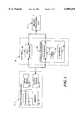
- FIG. 1the present disclosure describes a point-to-point network protocol and system 10 for using such a protocol.
- the system 10includes a first processing unit 12 for sending at least a voice signal from a first user to a second user.
- the first processing unit 12includes a processor 14, a memory 16, an input device 18, and an output device 20.
- the output device 20includes at least one modem capable of, for example, 14.4 Kilobit-per-second communications and operatively connected via wired and/or wireless communication connections to the Internet or other computer networks such as an Intranet, i.e., a private computer network.
- the input device 18may be implemented at least in part by the modem of the output device 20 to allow input signals from the communication connections to be received.
- the second processing unit 22may have a processor, memory, and input and output devices, including at least one modem and associated communication connections, as described above for the first processing unit 12.
- each of the processing units 12, 22may execute the WEBPHONE® Internet telephony application available from NetSpeak Corporation, Boca Raton, Fla., which is capable of performing the disclosed point-to-point Internet protocol and system 10, as described herein.
- the first processing unit 12 and the second processing unit 22are operatively connected to the Internet 24 by communication devices and software known in the art, such as an Internet Service Provider (ISP) or an Internet gateway.
- ISPInternet Service Provider
- the processing units 12, 22may be operatively interconnected through the Internet 24 to a connection server 26, and may also be operatively connected to a mail server 28 associated with the Internet 24.
- the connection server 26includes a processor 30, a timer 32 for generating time stamps, and a memory such as a database 34 for storing, for example, E-mail and Internet Protocol (IP) addresses of logged-in units.
- the connection server 26may be a SPARC 5 server or a SPARC 20 server, available from SUN MICROSYSTEMS, INC., Mountain View, Calif., having a central processing unit (CPU) as processor 30, an operating system (OS) such as UNIX, for providing timing operations such as maintaining the timer 32, a hard drive or fixed drive, as well as dynamic random access memory (DRAM) for storing the database 34, and a keyboard and display and/or other input and output devices (not shown in FIG. 1).
- the database 34may be an SQL database available from ORACLE or INFORMIX.
- the mail server 28may be implemented with a Post Office Protocol (POP) Version 3 mail server and the Simple Mail Transfer Protocol (SMTP), including a processor, memory, and stored programs operating in a UNIX environment, or, alternatively, another OS, to process E-mail capabilities between processing units and devices over the Internet 24.
- POPPost Office Protocol
- SMTPSimple Mail Transfer Protocol
- the POP protocolis utilized to retrieve E-mail messages from mail server 28 while the SMTP protocol is used to submit E-mail message to Internet 24.
- the first processing unit 12may operate the disclosed point-to-point Internet protocol by a computer program described hereinbelow in conjunction with FIG. 6, which may be implemented from compiled and /or interpreted source code in the C++ programming language and which may be downloaded to the first processing unit 12 from an external computer.
- the operating computer programmay be stored in the memory 16, which may include about 8 MB RAM and/or a hard or fixed drive having about 8 MB of available memory.
- the source codemay be implemented in the first processing unit 12 as firmware, as an erasable read only memory (EPROM), etc. It is understood that one skilled in the art would be able to use programming languages other than C++ to implement the disclosed point-to-point network protocol and system 10.
- the processor 14receives input commands and data from a first user associated with the first processing unit 12 though the input device 18, which may be an input port connected by a wired, optical, or a wireless connection for electromagnetic transmissions, or alternatively may be transferable storage media, such as floppy disks, magnetic tapes, compact disks, or other storage media including the input data from the first user.
- the input device 18may be an input port connected by a wired, optical, or a wireless connection for electromagnetic transmissions, or alternatively may be transferable storage media, such as floppy disks, magnetic tapes, compact disks, or other storage media including the input data from the first user.
- the input device 18may include a user interface (not shown) having, for example, at least one button actuated by the user to input commands to select from a plurality of operating modes to operate the first processing unit 12.
- the input device 18may include a keyboard, a mouse, a touch screen, and/or a data reading device such as a disk drive for receiving the input data from input data files stored in storage media such as a floppy disk or, for example, an 8 mm storage tape.
- the input device 18may alternatively include connections to other computer systems to receive the input commands and data therefrom.
- the first processing unit 12may include a visual interface for use in conjunction with the input device 18 and output device 20 similar to those screens illustrated in FIGS. 5-6, discussed below. It is also understood that alternative devices may be used to receive commands and data from the user, such as keyboards, mouse devices, and graphical user interfaces (GUI) such as WINDOWSTM 3.1 available form MICROSOFT Corporation, Redmond, Wash., and other operating systems and GUIs, such as OS/2 and OS/2 WARP, available from IBM CORPORATION, Boca Raton, Fla. Processing unit 12 may also include microphones and/or telephone handsets for receiving audio voice data and commands, speech or voice recognition devices, dual tone multi-frequency (DTMF) based devices, and/or software known in the art to accept voice data and commands and to operate the first processing unit 12.
- GUIgraphical user interfaces
- Processing unit 12may also include microphones and/or telephone handsets for receiving audio voice data and commands, speech or voice recognition devices, dual tone multi-frequency (DTMF) based devices, and/or software known in the
- either of the first processing unit 12 and the second processing unit 22may be implemented in a personal digital assistant (PDA) providing modem and E-mail capabilities and Internet access, with the PDA providing the input/output screens for mouse interactions or for touchscreen activation as shown, for example, in FIGS. 5-6, as a combination of the input device 18 and output device 20.
- PDApersonal digital assistant
- the illustrative embodiment of the disclosed point-to-point Internet protocol and system 10is presented as having individual functional blocks, which may include functional blocks labeled as "processor” and "processing unit".
- the functions represented by these blocksmay be provided through the use of either shared or dedicated hardware, including, but not limited to, hardware capable of executing software.
- the functions of each of the processors and processing units presented hereinmay be provided by a shared processor or by a plurality of individual processors.
- the use of the functional blocks with accompanying labels hereinis not to be construed to refer exclusively to hardware capable of executing software.
- Illustrative embodimentsmay include digital signal processor (DSP) hardware, such as the AT&T DSP16 or DSP32 C, read-only memory (ROM) for storing software performing the operations discussed below, and random access memory (RAM) for storing DSP results.
- DSPdigital signal processor
- ROMread-only memory
- RAMrandom access memory
- VLSIVery large scale integration
- the processing units 12, 22are capable of placing calls and connecting to other processing units connected to the Internet 24, for example, via dialup SLIP/PPP lines.
- each processing unitassigns an unsigned long session number, for example, a 32-bit long sequence in a *.ini file for each call.
- Each callmay be assigned a successive session number in sequence, which may be used by the respective processing unit to associate the call with one of the SLIP/PPP lines, to associate a ⁇ ConnectOK> response signal with a ⁇ Connect Request> signal, and to allow for multiplexing and demultiplexing of inbound and outbound conversations on conference lines, as explained hereinafter.
- the caller (or calling) processing unitmay open a "socket", i.e. a file handle or address indicating where data is to be sent, and transmit a ⁇ Call> command to establish communication with the callee utilizing, for example, datagram services such as Internet Standard network layering as well as transport layering, which may include a Transport Control Protocol (TCP) or a User Datagram Protocol (UDP) on top of the IP.
- a processing unit having a fixed IP addressmay maintain at least one open socket and a called processing unit waits for a ⁇ Call> command to assign the open socket to the incoming signal.
- the callee processing unitsends a BUSY signal or message to the caller processing unit.
- the disclosed point-to-point Internet protocol and system 10operate when a callee processing unit does not have a fixed or predetermined IP address.
- the first processing unit 12is the caller processing unit and the second processing unit 22 is the callee processing unit.
- the respective unitis provided a dynamically allocated IP address by an Internet service provider.
- the first processing unit 12Upon the first user initiating the point-to-point Internet protocol when the first user is logged on to the Internet 24, the first processing unit 12 automatically transmits its associated E-mail address and its dynamically allocated IP address to the connection server 26. The connection server 26 then stores these addresses in the database 34 and time stamps the stored addresses using timer 32. The first user operating the first processing unit 12 is thus established in the database 34 as an active on-line party available for communication using the disclosed point-to-point Internet protocol. Similarly, a second user operating the second processing unit 22, upon connection to the Internet 24 through an Internet service provider, is processed by the connection server 26 to be established in the database 34 as an active on-line party.
- the connection server 26may use the time stamps to update the status of each processing unit; for example, after 2 hours, so that the on-line status information stored in the database 34 is relatively current.
- Other predetermined time periodssuch as a default value of 24 hours, may be configured by a systems operator.
- the first user with the first processing unit 12initiates a call using, for example, a Send command and/or a command to speeddial an N TH stored number, which may be labeled [SND] and [SPD] [N], respectively, by the input device 18 and/or the output device 20, such as shown in FIGS. 5-6.
- the first processing unit 12retrieves from memory 16 a stored E-mail address of the callee corresponding to the N TH stored number.
- the first usermay directly enter the E-mail address of the callee.
- the first processing unit 12then sends a query, including the E-mail address of the callee, to the connection server 26.
- the connection server 26searches the database 34 to determine whether the callee is logged-in by finding any stored information corresponding to the callee's E-mail address indicating that the callee is active and on-line. If the callee is active and on-line, the connection server 26 then performs the primary point-to-point Internet protocol; i.e. the IP address of the callee is retrieved from the database 34 and sent to the first processing unit 12.
- the first processing unit 12may then directly establish the point-to-point Internet communications with the callee using the IP address of the callee.
- connection server 26If the callee is not on-line when the connection server 26 determines the callee's status, the connection server 26 sends an OFF-LINE signal or message to the first processing unit 12.
- the first processing unit 12may also display a message such as "Called Party Off-Line" to the first user.
- connection server 26updates the status of the user in the database 34; for example, by removing the user's information, or by flagging the user as being off-line.
- the connection server 26may be instructed to update the user's information in the database 34 by an off-line message, such as a data packet, sent automatically from the processing unit of the user prior to being disconnected from the connection server 26. Accordingly, an off-line user is effectively disabled from making and/or receiving point-to-point Internet communications.
- the disclosed secondary point-to-point Internet protocolmay be used as an alternative to the primary point-to-point Internet protocol described above, for example, if the connection server 26 is non-responsive, unreachable, inoperative, and/or unable to perform the primary point-to-point Internet protocol, as a non-responsive condition.
- the disclosed secondary point-to-point Internet protocolmay be used independent of the primary point-to-point Internet protocol.
- the first processing unit 12sends a ⁇ ConnectReq> message via E-mail over the Internet 24 to the mail server 28.
- the E-mail including the ⁇ ConnectReq> messagemay have, for example, the subject
- nnn.nnn.nnn.nnnn.nnn.nnn.is the current (i.e. temporary or permanent) IP address of the first user
- XXXXXXXis a session number, which may be unique and associated with the request of the first user to initiate point-to-point communication with the second user.
- E-mail messagesare transmitted to a remote users post office protocol server via simple mail transport protocol using MIME by the event manager, as explained hereinafter.
- E-mail messagesare received from a local WebPhone users POP server via the POP protocol using MIME by the event manager, as explained hereinafter.
- the first processing unit 12may send the ⁇ ConnectReq> message in response to an unsuccessful attempt to perform the primary point-to-point Internet protocol.
- the first processing unit 12may send the ⁇ ConnectReq> message in response to the first user initiating a SEND command or the like.
- the first processing unit 12opens a socket and waits to detect a response from the second processing unit 22.
- a timeout timersuch as timer 32, may be set by the first processing unit 12, in a manner known in the art, to wait for a predetermined duration to receive a ⁇ ConnectOK> signal.
- the processor 14 of the first processing unit 12may cause the output device 20 to output a Ring signal to the user, such as an audible ringing sound, about every 3 seconds.
- the processor 14may output a *.wav file, which may be labeled RING.WAV, which is processed by the output device 20 to output an audible ringing sound.
- Second processing unit 22polls mail server 28 at an interval, for example, once a minute, to check for incoming E-mail. Generally, second processing unit 22 checks the messages stored on mail server 28 at regular intervals to wait for and detect incoming E-mail indicating a ⁇ CONNECT REQ> message from first processing unit 12.
- E-mail for a specific usermay be sent over Internet 24 and directed to the permanent IP address of the mail server providing the target user's mail services.
- the E-mailis transported by a standard protocol, for example, SMTP, and stored into memory (not shown in FIG. 1) associated with mail server 28.
- the E-mailmay subsequently be retrieved by processing unit 22 on behalf of the user with another standard protocol, for example POP 3.
- POP 3another standard protocol
- the actual IP address utilized by the user's processing unitis immaterial to the retrieval of E-mail, as the mail server 28 can, for example, be polled or queried from any point on the network.
- the second processing unit 22may assign or may be assigned a temporary IP address. Therefore, the delivery of the E-mail through the Internet 24 provides the second processing unit 22 with a session number as well as IP addresses of both the first processing unit 12 and the second processing unit 22.
- Point-to-point communicationmay then be established by the processing unit 22 processing the E-mail signal to extract the ⁇ ConnectRequest> message, including the IP address of the first processing unit 12 and the session number.
- the second processing unit 22may then open a socket and generate a ⁇ ConnectOK> response signal, which includes the temporary IP address of the second processing unit 22 as well as the session number of the first processing unit.
- the second processing unit 22sends the ⁇ ConnectOK> signal directly over the Internet 24 to the IP address of the first processing unit 12 without processing by the mail server 28, and a timeout timer of the second processing unit 22 may be set to wait and detect a ⁇ Call> signal expected from the first processing unit 12.
- Real-time point-to-point communication of audio signals over the Internet 24, as well as video and voicemailmay thus be established and supported without requiring permanent IP addresses to be assigned to either of the users or processing units 12, 22.
- the relative permanence of the current IP addresses of the processing units 12, 22is sufficient, whether the current IP addresses were permanent (i.e. predetermined or preassigned) or temporary (i.e. assigned upon initiation of the point-to-point communication).
- a first user operating the first processing unit 12is not required to be notified by the first processing unit 12 that an E-mail is being generated and sent to establish the point-to-point link with the second user at the second processing unit 22.
- the second useris not required to be notified by the second processing unit 22 that an E-mail has been received and/or a temporary IP address is associated with the second processing unit 22.
- the processing units 12, 22may perform the disclosed point-to-point Internet protocol automatically upon initiation of the point-to-point communication command by the first user without displaying the E-mail interactions to either user. Accordingly, the disclosed point-to-point Internet protocol may be transparent to the users.
- either of the first and second usersmay receive, for example, a brief message of "CONNECTION IN PROGRESS" or the like on a display of the respective output device of the processing units 12, 22.
- the point-to-point communication link over the Internet 24may be established as shown in FIGS. 3-4 in a manner known in the art.
- the first processing unit 12upon receiving the ⁇ ConnectOK> signal from the second processing unit 22, extracts the IP address of the second processing unit 22 and the session number, and the session number sent from the second processing unit 22 is then checked with the session number originally sent from the first processing unit 12 in the ⁇ ConnectReq> message as E-mail.
- the first processing unit 12sends a ⁇ Call> signal directly over the Internet 24 to the second processing unit 22; i.e. using the IP address of the second processing unit 22 provided to the first processing unit 12 in the ⁇ ConnectOK> signal.
- the second processing unit 22may then begin a ring sequence, for example, by indicating or annunciating to the second user that an incoming call is being received. For example, the word "CALL" may be displayed on the output device of the second processing unit 22. The second user may then activate the second processing unit 22 to receive the incoming call.
- realtime audio and/or video conversationsmay be conducted in a manner known in the art between the first and second users through the Internet 24, for example, by compressed digital audio signals.
- Each of the processing units 12, 22also display to each respective user the words "IN USE" to indicate that the point-to-point communication link is established and audio or video signals are being transmitted.
- either usermay terminate the point-to-point communication link by, for example, activating a termination command, such as by activating an [END] button or icon on a respective processing unit, causing the respective processing unit to send an ⁇ End> signal which causes both processing units to terminate the respective sockets, as well as to perform other cleanup commands and functions known in the art.
- a termination commandsuch as by activating an [END] button or icon on a respective processing unit, causing the respective processing unit to send an ⁇ End> signal which causes both processing units to terminate the respective sockets, as well as to perform other cleanup commands and functions known in the art.
- FIGS. 5-6illustrate examples of display screens 36 which may be output by a respective output device of each processing unit 12, 22 of FIGS. 1-4 for providing the disclosed point-to-point Internet protocol and system 10.
- Such display screensmay be displayed on a display of a personal computer (PC) or a PDA in a manner known in the art.
- PCpersonal computer
- PDApersonal digital assistant
- a first display screen 36includes a status area 38 for indicating, for example, a called user by name and/or by IP address or telephone number; a current function such as C2; a current time; a current operating status such as "IN USE", and other control icons such as a down arrow icon 40 for scrolling down a list of parties on a current conference line.
- the operating statusmay include such annunciators as "IN USE,” “IDLE,” “BUSY,” “NO ANSWER,” “OFFLINE,” “CALL,” “DIALING,” “MESSAGES,” and “SPEEDDIAL.”
- Other areas of the display screen 36may include activation areas or icons for actuating commands or entering data.
- the display screen 36may include a set of icons 42 arranged in columns and rows including digits 0-9 and commands such as END, SND, HLD, etc.
- the END and SND commandsmay be initiated as described above, and the HLD icon 44 may be actuated to place a current line on hold.
- Such iconsmay also be configured to substantially simulate a telephone handset or a cellular telephone interface to facilitate ease of use, as well as to simulate function keys of a keyboard.
- icons labeled L1-L4may be mapped to function keys F1-F4 on standard PC keyboards, and icons C1-C3 may be mapped to perform as combinations of function keys, such as CTRL-F1, CTRL-F2, and CTRL-F3, respectively.
- the icons labeled L1-L4 and C1-C3may include circular regions which may simulate lamps or light emitting diodes (LEDs) which indicate that the function or element represented by the respective icon is active or being performed.
- LEDslight emitting diodes
- Icons L1-L4may represent each of 4 lines available to the caller, and icons C1-C3 may represent conference calls using at least one line to connect, for example, two or more parties in a conference call.
- the icons L1-L4 and C1-C3may indicate the activity of each respective line or conference line.
- icons L1-L2may have lightly shaded or colored circles, such as a green circle, indicating that each of lines 1 and 2 are in use
- icons L3-L4may have darkly shaded or color circles, such as a red or black circle, indicating that each of lines 3 and 4 are not in use.
- the lightly shaded circle of the icon labeled C2indicates that the function corresponding to C2 is active, as additionally indicated in the status are 38, while darkly shaded circles of icons labeled C1 and C3 indicate that such corresponding functions are not active.
- the icons 42are used in conjunction with the status area 38. For example, using a mouse for input, a line that is in use, as indicated by the lightly colored circle of the icon, may be activated to indicate a party's name by clicking a right mouse button for 5 seconds until another mouse click is actuated or the [ESC] key or icon is actuated. Thus, the user may switch between multiple calls in progress on respective lines.
- a usermay enter the name or alias or IP address, if known, of a party to be called by either manually entering the name, by using the speeddial feature, or by double clicking on an entry in a directory stored in the memory, such as the memory 16 of the first processing unit 12, where the directory entries may be scrolled using the status area 38 and the down arrow icon 40.
- the usermay transfer the called party to another line or a conference line by clicking and dragging the status area 38, which is represented by a reduced icon 46. Dragging the reduced icon 46 to any one of line icons L1-L4 transfers the called party in use to the selected line, and dragging the reduced icon 46 to any one of conference line icons C1-C3 adds the called party to the selected conference call.
- icons 48-52may be supported, such as icons 48-52, where icon 48 corresponds to, for example, an ALT-X command to exit the communication facility of a processing unit, and icon 50 corresponds to, for example, an ALT-M command to minimize or maximize the display screen 36 by the output device of the processing unit.
- Icon 52corresponds to an OPEN command, which may, for example, correspond to pressing the O key on a keyboard, to expand or contract the display screen 36 to represent the opening and closing of a cellular telephone.
- An “opened” configurationis shown in FIG. 5, and a “closed” configuration is shown in FIG. 6.
- additional featuressuch as output volume (VOL) controls, input microphone (MIC) controls, waveform (WAV) sound controls, etc.
- a wired telephone or wireless cellular telephonemay include various keys, LEDs, liquid crystal displays (LCDs), and touchscreen actuators corresponding to the icons and features shown in FIGS. 5-6.
- a PCmay have the keys of a keyboard and mouse mapped to the icons and features shown in FIGS. 5-6.
- First processing unit 12initiates the point-to-point Internet protocol in step 56 by sending a query from the first processing unit 12 to the connection server 26. If connection server 26 is operative to perform the point-to-point Internet protocol, in step 58, first processing unit 12 receives an on-line status signal from the connection server 26, such signal may include the IP address of the callee or a "Callee Off-Line" message. Next, first processing unit 12 performs the primary point-to-point Internet protocol in step 60, which may include receiving, at the first processing unit 12, the IP address of the callee if the callee is active and on-line. Alternatively, processing unit 60 may initiate and perform the secondary point-to-point Internet protocol in step 62, if connection server 26 is not operable.
- Connection server 26starts the primary point-to-point Internet protocol, in step 64, and timestamps and stores E-mail and IP addresses of logged-in users and processing units in the database 34 in step 66.
- Connection server 26receives a query from a first processing unit 12 in step 68 to determine whether a second user or second processing unit 22 is logged-in to the Internet 24, with the second user being specified, for example, by an E-mail address.
- Connection server 26retrieves the IP address of the specified user from the database 34 in step 70, if the specified user is logged-in to the Internet, and sends the retrieved IP address to the first processing unit 12 in step 72 to enable first processing unit 12 to establish point-to-point communications with the specified second user.
- First processing unit 12generates an E-mail signal, including a session number and a first IP address corresponding to a first processing unit in step 76.
- First processing unit 12transmits the E-mail signal as a ⁇ ConnectRequest> signal to the Internet 24 in step 78.
- the E-mail signalis delivered through the Internet 24 using a mail server 28 to the second processing unit 22 in step 80.
- Second processing unit 22extracts the session number and the first IP address from the E-mail signal in step 82 and transmits or sends the session number and a second IP address corresponding to the second processing unit 22, back to the first processing unit 12 through the Internet 24, in step 84.
- First processing unit 12verifies the session number received from the second processing unit 22 in step 86, and establishes a point-to-point Internet communication link between the first processing unit 12 and second processing unit 22 using the first and second IP addresses in step 88.
- connection server 26provides only directory and information related services.
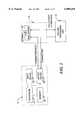
- FIG. 10illustrates an exemplary computer network 1000 over which the invention may operate.
- a first processing unit 1012is coupled to a computer network, illustrated here as the Internet 1010, through an Internet service provider 1014.
- a second processing unit 1022is coupled to Internet 1010 through Internet service provider 1018.
- the inventive directory server 1020is similarly coupled to Internet 1010 through Internet service provider 1026.
- Directory server 1020further comprises a connection server 1022 and information server 1024, as will be explained hereinafter.
- the first processing unit 1012, second processing unit 1022 and directory server 1020are operatively coupled to each other via the Internet 1010.
- network 1000is not restricted to implementation over the Internet 1010 but may comprise other network configurations such as a local area network (LAN), a wide area network (WAN), a global area network or any number of private networks currently referred to as an Intranet.
- LANlocal area network
- WANwide area network
- Intranetany number of private networks currently referred to as an Intranet.
- Such networksmay be implemented with any number of hardware and software components, transmission media and network protocols.
- FIG. 11illustrates the system architecture for a computer system 1100 such as an IBM PS/2®, suitable for implementing first and second processing units 1012 and 1022, respectively, of FIG. 10, as well as global server 1020.
- the exemplary computer system of FIG. 11is for descriptive purposes only. Although the description may refer to terms commonly used in describing particular computer systems, such as in IBM PS/2 computer, the description and concepts equally apply to other computer systems ranging from personal digital assistants (PDAs) to workstations to mainframe systems.
- PDAspersonal digital assistants
- Computer system 1100includes a central processing unit (CPU) 1105, which may be implemented with a conventional microprocessor.
- System 1100further includes a random access memory (RAM) 1110 for temporary storage of information, and a read only memory (ROM) 1115 for permanent storage of information.
- RAMrandom access memory
- ROMread only memory
- a memory controller 1120is provided for controlling RAM 1110.
- a bus 1130interconnects the components of computer system 1100.
- a bus controller 1125is provided for controlling bus 1130.
- An interrupt controller 1135is used for receiving and processing various interrupt signals from the system components.
- Mass storagemay be provided by diskette 1142, CD ROM 1147, or hard drive 1152. Data and software may be exchanged with computer system 1100 via removable media such as diskette 1142 and CD ROM 1147.
- Diskette 1142is insertable into diskette drive 1141 which is, in turn, connected to bus 1130 by a controller 1140.
- CD ROM 1147is insertable into CD ROM drive 1146 which is, in turn, connected to bus 1130 by controller 1145.
- Hard disk 1152is part of a fixed disk drive 1151 which is connected to bus 1130 by controller 1150.
- Computer system 100may be provided by a number of devices.
- a keyboard 1156 and mouse 1157are connected to bus 1130 by controller 1155.
- An audio transducer 1196which may act as both a microphone and a speaker, is connected to bus 1130 by audio controller 1197, as illustrated. It will be obvious to those reasonably skilled in the art that other input devices, such as a pen and/or tablet may be connected to bus 1130 with an appropriate controller and software, as required.
- DMA controller 1160is provided for performing direct memory access to RAM 1110.
- a visual displayis generated by video controller 1165 which controls video display 1170.
- Computer system 1100also includes a communications adaptor 1190 which allows the system to be interconnected to a network such as a local area network (LAN), a wide area network (WAN), or the Internet, schematically illustrated by transmission medium 1191 and network 1195.
- LANlocal area network
- WANwide area network
- Internetschematically illustrated by transmission medium 1191 and network 1195.
- computer system 1100may include an Intel microprocessor such as the 80486DX-33 MHz, or faster, a 14.4 Kb communication modem or faster, and a sound card, as further described with reference to FIG. 12.
- Intel microprocessorsuch as the 80486DX-33 MHz, or faster, a 14.4 Kb communication modem or faster, and a sound card, as further described with reference to FIG. 12.
- Operation of computer system 1100is generally controlled and coordinated by operating system software, such as the OS/2® operating system, available from International Business Machines Corporation, Boca Raton, Fla., or Windows® DOS-based operating system available from Microsoft Corp., Redmond, Wash.
- operating system softwaresuch as the OS/2® operating system, available from International Business Machines Corporation, Boca Raton, Fla., or Windows® DOS-based operating system available from Microsoft Corp., Redmond, Wash.
- the operating systemcontrols allocation of system resources and performs tasks such as process scheduling, memory management, networking, and I/O services, among other things.
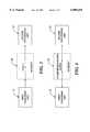
- FIG. 12illustrates schematically an audio sound card 1200 which may be used to implement audio controller 1197 of FIG. 11.
- sound card 1200may comprise, in the exemplary embodiment, an analog-to-digital (A/D) converter 1212, an input buffer 1216, a digital signal processor (DSP) 1222, ROM 1224, RAM 1226, an output buffer 1220, and an analog-to-digital (D/A) converter 1218, all of which may be interconnected over a bus 1210.
- Bus 1210is in turn coupled to a bus interface 1228 which, in turn, is coupled to bus controller 1125 of computer system 1100 of FIG. 11.
- A/D converter 1212is coupled to audio transducer 1214 which is typically a microphone.
- D/A converter 1218is coupled to audio transducer 1230, typically a speaker. It will be obvious to those reasonably skilled in the art that audio transducers 1214 and 1230, may be combined into a single element which serves as both a transmitter and receiver of audio signal.
- A/D converter 1212samples the audio signals supplied to it by transducer 1214 and stores the digital samples in buffer 1216.
- the digital samplingoccurs under control of a program typically stored in ROM 1224, or, alternatively, under the control of digital signal processor 1222.
- the digital samples stored in input buffer 1216are forwarded periodically, typically when the buffer reaches near capacity, over bus 1210 to bus 1130 of FIG. 11, for further processing by computer system 1100.
- the device driver for audio sound card 1200generates system interrupts which will cause the digital samples stored in input buffer 1216 to be retrieved for processing.
- the digital samplesare uncompressed as supplied to computer system 1100. However, compression of the digital samples may occur using DSP 1222 executing an appropriate compression algorithm, if desired.
- Digital audio samples from computer system 1100are also be converted to analog signals by sound card 1200.
- the digital samplesare supplied to bus 1210 and temporarily stored into output buffer 1220.
- the digital samplesare then converted by D/A converter 1218 into an analog signals which are then supplied to audio transducer 1230, i.e., a speaker, or to further amplification and processing devices.
- Sound card 1200 contemplated for use with the present inventionmay be implemented with any number of Windows compliant sound cards, such as the Sound Blaster sound card, commercially available from Creative Technologies Ltd., Singapore.
- Windows compliant sound cardshave a Windows compliant software interface allowing a standardized mechanism for software programs to operate the sound card device, such as Winsock 1.1.
- each of first processing unit 1012 and second processing unit 1022 of FIG. 10are executing a software application capable of enabling point-to-point communication over network 1000, such as an Internet telephone application.
- a software applicationcapable of enabling point-to-point communication over network 1000, such as an Internet telephone application.
- One such application suitable for use with the present inventionis the WebPhone Version 1.0 or higher, software, hereafter referred as the "WebPhone," commercially available from NetSpeak Corporation, Boca Raton, Fla.
- WebPhonesoftware
- FIGS. 5-6, 13A-B and 14An extensive detailed description of the architecture, application program interface, graphic user interface, and operation of the WebPhone can be found in copending U.S. patent application Ser. No.
- the WebPhoneis an end-user software application which enables users to send real-time audio data to other WebPhone users over the Internet or any public or private TCP/IP based computer networks.
- the WebPhone application and architecturemay be designed to run on any number of operating systems or computer architectures.
- the WebPhone applicationis implemented as a Windows compatible application executable on an IBM PC architecture or a clone thereof.
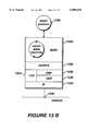
- the WebPhone 1300comprises a set of object modules, written in a programming language such as C++, which work together in a concerted fashion to provide real-time, multitasking, network-based media transmission and reception.
- WebPhone 1300comprises a graphic user interface (GUI) 1310, a user interface (UI) 1312, an event manager 1314, a media engine 1316, a database dynamic link library 1318, one or more audio compression/decompression (codecs) 1320, an audio manager 1324, a WebPhone application program interface (API) 1326, and a network interface 1322.
- GUIgraphic user interface
- UIuser interface
- APIapplication program interface
- WebPhone GUI 1310comprises the visual objects seen on a computer display by the user, as illustrated by the screen capture of FIG. 14 discussed hereinafter.
- WebPhone GUI 1310serves only to display the artwork associated with the underlying objects of WebPhone UI 1312.
- WebPhone GUI 1310may be implemented in a modular fashion distinct from the WebPhone UI for rapid portability. In this manner, other graphic user interface environments such as those compatible with the Macintosh, X-Windows or OS/2 operating systems, may be substituted via the Plug and Play protocol, as would be understood by those reasonably skilled in the arts.
- the WebPhone UI 1312 objectsmaintain the state of the WebPhone GUI and provide feedback to the WebPhone GUI objects from events originating from either the user or the event manager 1314.
- WebPhone UI objectsnotify associated WebPhone GUI objects to display the appropriate art work to the user.
- WebPhone UI objectsalso interface with the database dynamic link library 1318 to maintain the WebPhone database information, e.g. configuration information, phone directory information, etc.
- the WebPhone event manager 1314processes all the events originating from the user, via WebPhone UI 1312, the media engine 1316, and WebPhone API 1326.
- Event manager 1314may be implemented as a table-driven state machine that processes the above-identified events and performs the functions necessary to bring the WebPhone from one state to another. For example, event manager 1314 interacts with media engine 1316 to create, control and remove concurrently executing jobs managed by media engine 1316.
- Event manager 1314also interfaces with the WebPhone API 1326 to provide communications with other WebPhones and connection servers, as described in more detail hereinafter.
- WebPhone database 1318is a dynamic link library of tree-based subroutines that provide fast database access to the WebPhone configuration information, personal phone directory, etc.
- WebPhone media engine 1316manages the allocation of associated resources to provide a multitasking environment and controls the flow of real-time data streams, e.g., conversations, outgoing messages, etc., and non-real-time data streams, e.g., voice mail, graphic images, files, etc., to and from a user network connection.
- the objects representing tasksare created by event manager 1314, thereby freeing media engine 1316 to manage resource routing.
- the media engineroutes data streams from sources such as a microphone, file or network socket, to destinations such as speaker, destination file or other network socket.
- the media engineinterfaces with the WebPhone API 1326 to control communication with other processes, and further communicates with audio manager 1324 to communicate with the system input/output apparatus, such as sound card 1200 of FIG. 12.
- Media engine 1314may be designed to employ heuristic methods to sense and efficiently utilize available bandwidth to achieve timely and accurate delivery of all data streams, both real-time and non-real-time.
- Media engine 1316further interacts with WebPhone codec 1320 to achieve compression and decompression of audio data streams.
- Codec 1320provides coding of digital samples from the sound card 1200 of FIG. 12 into a compressed format more suitable for transmission over a computer network.
- Codec 1320further provides decoding of a compressed signal prior to its submission to sound card 1200 for subsequent conversion to an audible analog signal.
- WebPhone codec 1320is implemented in a modular fashion so that codecs may be replaced and updated with newer, more efficient compression/decompression algorithms via the Plug and Play protocol.
- a codec suitable for use with the present inventionis the True Speech codec, version 8.5, commercially available from the DSP Group, Inc., Santa Clara, Calif.
- the True Speech codecis an enhanced linear predicative coding algorithm, specifically designed to efficiently encode and decode human speech data.
- the True Speech codecsamples the digital sample stream from sound card 1200, and, using a look-up table-based algorithm, tries to predict the value of the next data sample in the digital data stream based on the history of prior data sample values.
- the compressed data streamcomprises a combination of identifiers of the predicted sample values, as well as error values used to correct the predictive values. Accordingly, the amount of digital data actually transmitted to represent the audio signal is significantly reduced in comparison to transmission of the actual data samples generated by sound card 1200.
- the True Speech codecprovides temporal, frequency domain compression of the digital data representing the audio signal.
- Audio manager 1324handles communication with the audio sound card 1200 and presents a common interface to media engine 1314. Audio manager 1324 interfaces with sound card 1200 through one or more application program interfaces. In the illustrative embodiment, audio manager 1324 utilizes low-level Microsoft Windows wave input/output routines to interface with MCI compliant sound cards. As with codecs 1320, audio manager 1324 may be implemented to adhere to the Plug and Play protocol so other compliant audio sound cards or circuits, such as those for the Apple Macintosh, commercially available from Apple Computer Company, Cupertino, Calif., or a Unix compatible sound card or circuit may interact with the audio manager 1324.
- the WebPhone API 1326enables the WebPhone to communicate with other WebPhones, connection and directory assistance servers, Internet gateway servers, credit processing servers, database access servers and other client processes implementing the WebPhone API.
- the WebPhone APIutilizes sockets, i.e., a file handle or address indicating where data is to be sent, allowing WebPhone API enabled processes to reside on the same computer, on a local area network, on a wide area network, or over the Internet.
- a process 1328communicates with the WebPhone API 1326 through a plurality of sockets 1322.
- the sockets 1322are accessible by network 1330 through a number of protocols including Internet Protocol (IP) 1332, Transmission Control Protocol (TCP) 1334, Real-Time Protocol (RTP) 1336 and User Datagram Protocol (UDP) 1338.
- IPInternet Protocol
- TCPTransmission Control Protocol
- RTPReal-Time Protocol
- UDPUser Datagram Protocol
- the WebPhone APIprovides remote command control of WebPhones and servers via the TCP.
- WebPhone API 1326transfers real-time and streamed audio via the UDP protocol and real-time audio and video data via the UDP and RTP protocols.
- the WebPhone APIutilizes TCP to transfer data of different types, i.e., file, image, graphics, etc. as well as to transfer streamline video and other multimedia data types, such as Java developed by Sun MicroSystems, Mountain View, Calif.
- the WebPhone APIprovides user definable commands and data types.
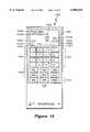
- FIG. 14illustrates the graphic display produced upon invoking the WebPhone application.
- Display 1400is an alternative embodiment to that illustrated in FIGS. 5-6 with similar graphic elements, icons and display areas functioning as previously described with reference to FIGS. 5-6.
- FIG. 15Aa network diagram, similar to that shown in FIG. 10, is illustrated, including a schematic diagram of the global server 1500 and the various devices operatively coupling server 1500 to the Internet 1530.
- a first processing unit executing the WebPhone applicationhereafter referred to as WebPhone 1536, is coupled to Internet 1530 through an Internet service provider 1532.
- a second processing unit executing the WebPhone applicationreferred to as WebPhone 1538, is coupled to the Internet 1530 by an Internet service provider 1534.
- Global server 1500is coupled to Internet 1530 by an Internet service provider 1528, a CSU/DSU 1526, a router 1524, and a fire wall server 1522.
- fire wall server 1522 and global server 1500are connected through a local area network 1520.
- Network 1520may be implemented with an Ethernet or other suitable transport for TCP/IP communications.
- server 1500may be connected directly to fire wall server 1522.
- firewall server 1522is a single firewall mechanism which protects unauthorized access from network 1530 into global server 1500.
- Firewall server 1522may be implemented on a work station, such as a SPARC 5 or SPARC 20 server from Sun MicroSystems, executing a commercially available firewall software application such as Raptor, available from Raptor Systems.
- the firewall serverprevents unauthorized access into global server 1500 and thereby prevents destruction of any of the information contained therein by checking the source of requests for information to global server 1500.
- Router 1524translates logical addresses among networked topologies and may be implemented with any number of commercial router devices such as the CISCO model 2501 router executing CISCO 11.0 software, both commercially available from CISCO Systems, Inc., San Jose, Calif.
- CSU/DSU 1526(Channel Send Unit/Data Send Unit) functions as a sophisticated modem, converting network data to high speed serial data for transfer over a T1 or T3 line. Such high speed data is connected to another CSU/DSU, typically at the telephone company over the T1 or T3 line.
- An apparatus suitable for use in implementing CSU/DSU 1526 in the present inventionis the AT&T Paradigm by AT&T Laboratories, Murray Hill, N.J.
- FIG. 15Afurther illustrates a logical schematic of global server 1500.
- the servercomprises a hardware platform 1508 on which an operating system 1510 executes.
- hardware platform 1508may comprise any number of commercially available high end work stations such as a DEC Alpha 4100 System, commercially available from Digital Equipment Corporation, Maynard, Mass., or a SPARC 5 or a SPARC 20, both commercially available from Sun Micro Systems, Mountain View, Calif.
- Operating system 1510in the illustrative embodiment, may comprise the Unix, commercially available from Novell, Windows NT, commercially available from Microsoft Corporation, or Solaris, commercially available from Sun MicroSystems, Inc. Executing on operating system 1510 are a number of processes including connection server 1512, information server 1514, database server 1518 and database 1516.
- Connection server 1512provides a directory information service to WebPhone client processes currently on-line with respect to the computer network.
- Connection server 1512behaves like a virtual machine within global server 1500 and interacts with database 1516 through database server 1518 and with network interface card 1540 through the WebPhone API.
- the basic function of connection server 1512is to provide a one-to-one mapping between an identifier of a WebPhone client process, such as a E-mail address, and the current IP address, dynamic or fixed, associated with that WebPhone client process.
- connection server 1512compares the E-mail address with the values of the records contained in on-line table 1516B and, if a match occurs with one of the records contained therein, transmits the value of the Internet Protocol address associated with that record to the requesting WebPhone client, i.e., a one-to-one matching between E-mail addresses and Internet Protocol addresses.
- connection server 1512a flow chart illustrating the basic process steps used by connection server 1512 to implement a one-to-one mapping of E-mail addresses to Internet Protocol addresses in accordance with the present invention is illustrated.
- the coding of the process steps of the flowchart of FIG. 16A into instructions suitable to control global server 1500will be understandable by those having ordinary skill in the art of programming.
- Connection server 1512remains in an idle state until a ⁇ CONNECT REQ> packet is transmitted from a WebPhone client to global server 1500, as illustrated by decisional block 1610 of FIG. 16A.
- connection server 1512Upon receipt of the packet, connection server 1512 extracts the E-mail address from the packet and supplies the E-mail address to database server 1518 which them communicates using the ODBC standard with database 1516 to perform a search of On-line Table 1516B, as illustrated by process blocks 1612 and 1614.
- Database 1516performs a search of on-line Table 1516B and supplies the current Internet Protocol address of the WebPhone client associated with the E-mail address to connection server 1512, via database server 1518. If a corresponding Internet Protocol address is found for the E-mail address contained in the query, connection server 1512 supplies the Internet protocol address to the requesting WebPhone client by transmitting a ⁇ CONNECT ACK> packet, as illustrated by decisional block 1616 and process block 1618.
- connection server 1512will send an ⁇ OFFLINE> packet to the WebPhone client, as illustrated by process block 1622.
- Connection server 1512will return to an idle state to await the receipt of another ⁇ CONNECT REQ> packet, as illustrated by FIG. 16A.
- FIG. 16AA description of the above described packets as well as a diagram illustrating the packet transfer sequence between a WebPhone client and global server 1500 can be found with reference to Tables 7-8 and FIG. 17A, respectively.
- Information server 1514provides an interface between requests from WebPhone client processes and database 1516.
- Information server 1514includes code written to extract the search criteria from an ⁇ INFO REQ> packet and supply the search criteria to the database search engine of database 1516 using the ODBC standard.
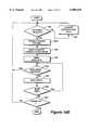
- FIG. 16Ba flow chart illustrating the basic process steps used by information server 1514 in performing information/directory service functions in accordance with the present invention is illustrated. The coding of the process steps of the flow chart into instructions suitable for execution by global server 1500 will be understood by those having ordinary skill in the art of programming.
- Information server 1514remains idle until an ⁇ INFO REQ> packet is received from a WebPhone client process, as illustrated by decisional step 1630.
- information server 1514extracts the data elements defined within the ⁇ INFO REQ> packet and supplies them to database server 1518 which, in turn, forward them to database 1516, as represented by the process step 1634 and 1636.
- the search engine contained within database 1516performs the search and supplies to information server 1514 all client records meeting the search criteria specified in the ⁇ INFO REQ> packet, or a message indicating that no records were found.
- information server 1514transmits a ⁇ INFO ACK> packet to the WebPhone client process indicating the number of records satisfying the search criteria, as indicated by process step 1638.
- the WebPhone clientmay wish to receive all records satisfying the search criteria, or, if the number is excessively large, may desire to further refine the search by transmitting a ⁇ INFO ABORT> packet to information server 1514 and defining new search parameters to be sent with a subsequent ⁇ INFO REQ> packet. If a ⁇ INFO ABORT> packet is received by information server 1514, the process will return to an idle state, as illustrated by decisional block 1640. If no ⁇ INFO ABORT> packet was received, information server 1514 will transmit one or more ⁇ INFO> packets to the requesting WebPhone client until all records have been received by the WebPhone client, as illustrated by process step 1642.
- Information server 1514will return to an idle state awaiting another ⁇ INFO REQ> packet, as illustrated in FIG. 16B.
- a description of the packets comprising the WebPhone protocolis illustrated in Tables 7-8 and a diagram illustrating the packet transfer sequence defined in FIG. 17A-B.
- Network interface card 1540interfaces with connection server 1512, information 1514, and database server 1518 using the WebPhone API definition, as described herein, and the Windows Sockets 1.1 Protocol, or, in a Unix-based operating system, Berkeley Sockets Network API.
- Network interface card 1514may comprise, in illustrative embodiment, an Ethernet card capable of transmitting data at rates of 100 Mbps or greater, such cards being commercially available through a number of different vendors.
- the connection from CSU/DSU 1526 to ISP 1528may comprise a T1 connection, i.e., a long-distance, digital, point-to-point communication circuit capable of transmitting a signal at 1.544 Mbps with 24 channels at 64 Kbps.
- a T3 connectionmay be used, i.e., a connection is similar to a T1 connection except it is capable of transmitting at 44.746 Mbps per second with up to 28 T1 channels.
- Other connectionsmay be suitable, depending on specific requirements and availability.
- Database 1516 of global server 1500may be implemented with any of a number of commercially available structured query language (SQL) database engines, such as Oracle 7.x, Informix, or Microsoft SQL server 6.x.
- SQLstructured query language
- the SQL databaseresides on a RAID 1 and RAID 5 mirrored disk array.
- database 1516interacts with control server 1512 and information server 1514 through database server 1518.
- database 1516comprises a Client table 1516A, an On-line table 1516B, a WebBoard table 1516C, a WebBoard configuration table 1516D and a WebBoard Source table 1516E.
- Client table 1516Acomprises a plurality of records, each of which may have the fields and corresponding data elements as described in Table 1.
- Each WebPhone userhereinafter "client” has a separate record in table 1516A containing the information defining the client's profile of personal information.
- the "activated,” “paid,” and “published” fieldsare boolean yes/no fields.
- the “id” fieldcomprises a unique ID sequence identifying a particular WebPhone client.
- the "activation date,” “address change date,” and “access date” fieldsare time references measured in seconds since 00:00 Coordinated Universal Time (UTC), Jan. 1, 1970.
- IPAddrrepresents the Internet protocol address of the WebPhone client and, if unknown, has a default value of 0.0.0.0.
- the database record containing a WebPhone client's profileis defined upon first logging-on to global server 1500 and may be updated each time a WebPhone user's profile changes, as explained hereinafter.
- the On-line table 1516Bprovides a dynamic list of those clients from 1516A who are currently On-line, as well as their current Internet protocol address.
- On-line Table 1516Bcomprises a plurality of records each of which may have the fields and data types illustrated in Table 2.
- the record entries of On-line table 1516Bare used by connection server 1512 and information server 1514, as explained hereinafter, to provide a directory of those WebPhone client processes currently having on-line status with respect to the computer network.
- the WebBoardTMis a virtual multimedia billboard which is transmitted as a series of multimedia data files to WebPhone client processes while the WebPhone application is activated.
- An extensive description of the WebBoard utility and its operationcan be found in copending U.S. patent application Ser. No. 08/719,891 entitled Method and Apparatus for Distribution of Multimedia Data Over a Computer Network by Mattaway et al., commonly assigned, the subject matter of which is incorporated herein by reference.
- WebBoard table 1516Cincludes a plurality of records each describing a specific WebBoard and having the field and data types illustrated in Table 3.
- the "id” field of Table 3provides a unique identification number for the WebBoard file.
- the "imageType” fielddefines the video format of the image such as JPEG, TIF, GIF, etc.
- the "audio” fielddefines the nature of the audio file, e.g.
- the "hits" fielddefines the number of times the WebBoard has been selected by WebPhone clients, while the "hits profile” field defines the file name of the file identifying those WebPhone clients generating hits to the subject WebBoard.
- the WebBoard configuration table 1516Dmay have at least one record having the fields and data types illustrated in Table 4.
- the count fieldrepresents the number of WebBoard records currently in the table 1516C.
- the WebBoard source table 1516Emay comprise a plurality of records each having the fields and data types defined in Table 5.
- the "URL" field of Table 5defines a data link in accordance with Uniform Resource Locator protocol to the home page or Web site of the source.
- any entityincluding vendors, advertisers, individuals or groups wishing to post information or having a Web site or home page may have a WebBoard displayable through the present invention.
- Database server 1518serves as the interface between database 1516 and connection server 1512 and information server 1514. Specifically, connection server 1512 and information server 1514 communicate with database engine 1518 through application program interfaces embedded in the code implementation of both the connection server and the information server. Database server 1518 communicates with database 1516, in the illustrative embodiment, using the open database connectivity (ODBC) standard, developed by Microsoft Corporation, Redmond, Wash. Database server 1518 functions to supply structured database queries to database 1516 and to supply the results therefrom to connection server 1514 and information server 1512.
- ODBCopen database connectivity
- database server 1518may be implemented as a "virtual machine" executing on global server 1500, or, alternatively, may be implemented on a separate computer system such as a DEC Alpha 4100 Workstation executing DEC Unix operating system, both available from Digital Equipment Corporation, Maynard, Mass.
- Database server 1518communicates with network interface card 1518 using the WebPhone Application Program Interface described herein.
- global server 1500is implemented as a single server apparatus on which a plurality of "virtual machines" execute simultaneously.
- a plurality of separate serversone dedicated to each of connection server 1512, information server 1514, and database server 1518 may be interconnected to database 1516 and to each other using a local area network, to form a composite "virtual" global server, as illustrated by FIG. 15B, the construction of the system illustrated in FIG. 15B being within the knowledge of those reasonably skilled in the art in light of the descriptions contained herein.
- more than one global server 1500may be utilized, as illustrated by FIG. 15C.
- multiple global servers 1500A-Dare maintained for fault tolerant load sharing, each one performing the above-described connection server, information server and database server processes.
- Each of global servers 1500A-Dare connected to the Internet via a separate T1 or T3 connection to different Internet service providers, and are synchronized with each other via database server replication.
- multiple global serversmay be located in close proximity or in geographically disparate locations.
- the WebPhone applicationis provided with the network address information of each global server 1500A-D. In the event that any one of the global servers initially contacted is nonresponsive the WebPhone application will attempt connection to one or more of the remaining global servers to obtain directory and information services.
- the global servercan provide the network address of another global server capable of servicing the WebPhone client's request or which is logically more convenient. This process may occur during the initial log-in of the WebPhone client process, as described with references to messages 1-5 of FIG. 17A.
- the WebPhone applicationcan rely on the secondary Internet Protocol technique in which a WebPhone client process sends its current dynamically assigned Internet Protocol address to a prospective WebPhone callee through an E-mail message, as described herein.
- Tables 6-7illustrate the packet definitions of the packets comprising the WebPhone protocol (WPP) including the packet type, the direction and the data elements comprising each packet.
- WPPWebPhone protocol
- Tables 8-9define the data elements described in Tables 6-7.
- the terms "ULONG” and “UNSIGNED LONG”designate an unsigned long integer value, i.e., 32-bit integer value.
- the terms “USHORT” and “UNSIGNED SHORT”designate an unsigned short integer value, i.e., 16-bit integer value.
- the term “CHAR”designates a single character, typically assuming a binary value of either 1 or 0.
- the term “VARCHAR(X)"where X is an integer, value symbolizes a variable length character string, with the number of characters indicated with the integer value.
- the term “UNSIGNED CHAR”designates an 8-bit character code, i.e., no sign bit.
- the term “variable”indicates a variable length data field.
- FIG. 17Aillustrates a schematic block diagram of a packet transfer sequence between a pair of WebPhone client processes and the global server, in accordance with the present invention.
- Each WebPhone applicationalso referred to as a WebPhone client process, connects to global server 1500 upon start up to inform global server 1500 that the WebPhone client process is on-line and available to make and/or receive calls.
- WebPhone 1536opens a socket to the global server 1500 and transmits an ⁇ ONLINE REQ> packet from WebPhone 1536 to Global server 1500, as illustrated by message 1 and FIG. 17A.
- the ⁇ ON LINE REQ> packetmay have the format and data illustrated in Table 6, and additional Feature bits which define the functionality of the WebPhone application, as explained in greater detail hereinafter.
- connection server 1512 and information server 1514 of global server 1500use the information contained in the ⁇ ONLINE REQ> packet to update the status of database 1516.
- global server 1500returns to the WebPhone 1536 a ⁇ USER INFO REQ> packet, as illustrated by message 2 of FIG. 17A.
- the ⁇ USER INFO REQ> packetincludes the elements as defined in Table 9.
- WebPhone 1536returns a ⁇ USER INFO> packet as illustrated by message 3 of FIG. 17A.
- the ⁇ USER INFO> packetcontains the data elements defined in Table 8.
- Connection server 1512 and information server 1514 of global server 1500utilize the data in the ⁇ USER INFO> packet to update database 1516.
- information server 1514utilizes such data to create a record in client table 1516A representing WebPhone 1536.
- global server 1500transmits to WebPhone 1536 a ⁇ REGISTRATION> packet, as illustrated by message 4 of FIG. 17A.
- the ⁇ REGISTRATION> packetcontains the data described in Table 7 plus Feature bits, as described hereinafter.
- the ⁇ REGISTRATION> packet returned to WebPhone 1536enables certain functions within the WebPhone architecture based on predetermined criteria, for example, whether the user has paid for the product, or which version of the product the user possesses.
- global server 1500further transmits an ⁇ ONLINE ACK> packet, as illustrated by message 5 of FIG. 17A.
- connection server 1514updates database 1516, specifically On-line table 1516B to indicate that WebPhone 1536 is on-line with respect to the computer network.
- WebPhone 1536closes the socket to global server 1500.
- WebPhone 1538interacts in a similar manner with global server 1500 to establish on-line status. No further interaction occurs between the respective WebPhone client processes and the global server unless the WebPhones require directory or search assistance about a prospective callee.
- a WebPhone userknows the E-mail address of another WebPhone user to which he/she wishes to establish a point-to-point communication, however, the current dynamically assigned Internet protocol address of the callee is unknown to the caller.
- the user of WebPhone 1536requests assistance from global server 1500 to obtain the current dynamically assigned Internet Protocol address of the prospective callee WebPhone.
- the user of WebPhone 1536specifies the callee by entering all or part of the callee party's name or alias in the party name field area of the graphic user interface.
- WebPhone 1536opens a socket to global server 1500 and transmits a ⁇ CONNECT REQ> packet having the format described in Table 6.
- Connection server 1512 of global server 1500utilizes the value of the E-mail address specified in the ⁇ CONNECT REQ> packet to perform a one-to-one mapping in the on-line table 1516B to determine the current Internet Protocol address of the indicated callee, as illustrated by the flowchart of FIG. 15A.
- the server 1500transmits to WebPhone 1536 a ⁇ CONNECT ACK> packet, as indicated by message 7A of FIG. 17A.
- the ⁇ CONNECT ACK> packethas the format and content as illustrated in Table 6 and includes the IP address of the callee as well as information such as an error code to indicate that no WebPhone application is associated with that callee.
- global server 1500transmits to WebPhone 1536 an ⁇ OFF LINE> packet to indicate that the desired party is not on-line, as illustrated by message 7B of FIG. 17A.
- the socket to global server 1500 opened by WebPhone 1536is closed.
- the packet transmission sequence illustrated between WebPhones 1536 and 1538 of FIG. 17Atranspires.
- a calling WebPhoneknows the Internet Protocol address of the callee WebPhone, as in the case of a fixed Internet Protocol address, or obtains the Internet Protocol address from global server 1500, as previously described, the calling sequence to establish a call occurs as follows.
- WebPhone 1536opens a socket to WebPhone 1538.
- WebPhone 1536transmits to WebPhone 1538 a ⁇ CALL> packet as illustrated by message 8 of FIG. 16A.
- the ⁇ CALL> packethas the format illustrated in Table 6 and may, optionally, include information identifying the compression/decompression (codec) used by the caller WebPhone.
- WebPhone 1538may return with a number of different packets, as illustrated by messages 9A-D.
- callee WebPhone 1538may respond to caller WebPhone 1538 with a ⁇ REJECT> packet, as illustrated by message 9A, indicating that the callee WebPhone does not wish to be disturbed, e.g. total call blocking, or, that the callee WebPhone does not wish to talk to caller WebPhone, e.g. party specific or group specific call blocking.
- the user information contained within the ⁇ CALL> packet of message 9Ais compared by the caller WebPhone application to a predefined list of WebPhone user information profiles which the callee does not wish to converse, such list having been predefined by the callee in the WebPhone user's personal directory, as explained hereinafter.
- the caller WebPhoneUpon receiving the ⁇ REJECT> packet the caller WebPhone annunciates the result to the user and the socket to the callee WebPhone is closed.
- callee WebPhone 1538may return a ⁇ BUSY> packet, as illustrated by message 9B of FIG. 17A.
- the ⁇ BUSY> packetindicates that the callee WebPhone is currently utilizing all available lines within its WebPhone application.
- a further possible response from callee WebPhone 1538is to issue an ⁇ ANSWER MACH> packet, as illustrated by message 9C of FIG. 17A.
- the ⁇ ANSWER MACH> packetincludes data indicating whether the machine is capable of receiving voice mail type messages, as described in greater detail in copending U.S. patent application Ser. No. 08/719,898 entitled "Method and Apparatus for Providing Caller Identification Based Out-Going Messages in a Computer Telephony Environment," by Mattaway et al., commonly assigned and incorporated herein by reference.
- the preferred response by callee WebPhone 1538is to transmit a call acknowledge ⁇ CALL ACK> packet, as illustrated by message 9D of FIG. 17A.
- the ⁇ CALL ACK> packethas the data content illustrated in Table 6.
- Both the ⁇ CALL> and ⁇ CALL ACK> packetscontain the information of the WebPhone users sending the packet. This information is useful by the recipient of the packet for a number of purposes. For example, the user information is displayed on the enunciator area of the WebPhone graphic display to identify the party placing the call.
- the usermay select such information and, using the drag and drop functionality of the WebPhone graphic user interface, add the user information to the callee WebPhone user's personal directory resident within his/her specific WebPhone application.
- both partiesare completely identified to each other prior to commencing audio communications.
- the transmission of complete caller identification information with the ⁇ CALL> and ⁇ CALL ACK> symbols packetsenables such functions as individual or group specific call blocking, party specific outgoing messages, visual caller identification, and party specific priority ringing and sound effects, as explained herein.
- the callee WebPhoneFollowing transmission of ⁇ CALL ACK> packet by callee WebPhone 1538, the callee WebPhone further transmits an ⁇ ANSWER> packet to caller WebPhone 1536, as illustrated by message 10 of FIG. 17A.
- the ⁇ ANSWER> packetis essentially empty, containing nothing more than a session ID number which is unique to the call.
- the socket previously opened by caller WebPhone 1536 over which the forgoing packets were transmittedremains open for the transmission of control information between caller WebPhone 1536 and callee WebPhone 1538.
- Such control informationmay comprise an ⁇ END> packet signaling the end of a call, a ⁇ HOLD> packet indicating that one of the parties to a call has placed the call "on hold” or other packets related to advance functionality of the WebPhone architecture.
- caller WebPhone 1536opens a second socket to callee WebPhone 1538 over which the respective WebPhones may exchange ⁇ AUDIO> packets, as illustrated by messages 11A-B of FIG. 17A.
- the ⁇ AUDIO> packetshave the data content illustrated in Table 6.
- the WebPhone applicationenables the parties to converse in real-time, telephone quality, encrypted audio communication over the Internet and other TCP/IP based networks.
- both WebPhone client processesare utilized with full duplex sound cards, such as that illustrated in FIG. 12, the WebPhone users may transmit and receive audio packets simultaneously, similar to normal telephone conversation. However, if the WebPhone client processes are used with half duplex sound cards, a WebPhone user may only transmit or receive audio data simultaneously, similar to a speaker phone. Exchange of ⁇ AUDIO> packets continues until either the callee WebPhone or the caller WebPhone transmits an ⁇ END> packet, as illustrated by message 12 of FIG. 16A. Following the receipt of an end packet, the WebPhone client process will cease to accept subsequent audio packets.
- the socket opened by the caller WebPhone to the callee WebPhone over which real-time audio communication occurredis closed.
- the previously opened socket over which control information was transmitted between the callee and caller WebPhonesis likewise closed.
- information server 1514may be utilized as described.
- the WebPhone userdefines One or more of the first name, last name, company, city, state, or country values of the Query field contained within the ⁇ INFO REQ> packet sends the packet to the global server.
- WebPhone 1536opens a socket to global server 1500 and forwards ⁇ INFO REQ> packet to global server 1500, as illustrated by message 1 of FIG. 17B.
- Information server 1514extracts the values specified the query field of the ⁇ INFO REQ> packet and queries the database 1516, as previously described with reference to FIG. 16B.
- Global server 1500then transmits a ⁇ INFO ACK> packet back to WebPhone 1536, as illustrated by message 2 of FIG. 17B.
- the ⁇ INFO ACK> packethas the format and data elements indicated in Table 7, including the number of parties satisfying the search criteria, specified in the ⁇ INFO REQ> packet. If the user of WebPhone 1536 wishes to receive the number of parties satisfying the search criteria global server 1500 automatically transmits to WebPhone 1536 one or more ⁇ INFO> packets, as illustrated by messages 3A-C of FIG. 17B.
- the ⁇ INFO> packethas the format and data elements as described in Tables 6-7.
- WebPhone 1536may transmit an ⁇ INFO ABORT> packet to either prevent transmission of any ⁇ INFO> packets or to stop transmission of any remaining packets, as illustrated by message 4 of FIG. 17B.
- the ⁇ INFO ABORT> packethas the format and data elements as described in Table 6-7.
- the usermay store such information in his/her personal WebPhone directory by dragging and dropping the information from the annunciator area to the direction dialog box using the WebPhone GUI.
- the methods and apparatus described hereinprovide computer users with a powerful protocol in which to directly establish real-time, point-to-point communications over computer networks directly without server required linking.
- the a directory serverassists in furnishing the current dynamically assigned internet protocol address of other similarly equipped computer users or information about such users.
- the WebPhone GUI 1400consists of a main window which has the look of a modern cellular flip phone and a set of dialog boxes launched from window. Operation of the WebPhone is controlled by selecting objects, i.e., buttons, text and images, and dragging objects, i.e., lines, parties, messages, etc., as explained hereinafter.
- objectsi.e., buttons, text and images
- dragging objectsi.e., lines, parties, messages, etc.
- WebPhone GUI 1400comprises a plurality of visual objects, including display 1402, number pad 1406, line pad 1404, call function buttons 1408, phone function buttons 1410 and audio controls (not shown).
- Display 1402provides a number of distinct area for presentation of entering of information useful in operation of the WebPhone application.
- a party name field 1402Adisplays the name of the caller when an incoming call arrives and may also be used for entering the name of a party, up to 25 characters.
- By entering the name of a party in the party name field 1402A and pressing one or more of the phone function buttons 1410various activities may be accommodated. For example, entering the name of a party in the party name field and pressing the [SND] button causes the WebPhone to first search the personal information directory for the information profile of the party entered.
- the WebPhonewill open up a directory assistance dialog allowing the user to enter information to be submitted to the information server 1514 for searching, as described previously. Further, clicking the entered party name with the right mouse button causes a dialog box to appear enabling the user to modify the current directory entry, if any, for the party entered.
- Entering the IP address of a party in the party IP address field followed by the [SND] buttoncauses initiation of a call. If the callee's name exists within the caller's personal directory, or the call is established, the callee's name will appear in a party name field for caller ID purposes.
- the third line of the display 1402serves as a status annunciator line for displaying iconic feedback about the status of events within the WebPhone.
- status iconsmay include icons indicating enablement of call forwarding, call blocking, do not disturb, priority ringing, file transfer occurring, voice mail transfer occurring or call camping.
- the line number annunciatorindicates the line, i.e., lines 1-4, currently active, as illustrated by annunciated field 1402J.
- a main LED 1402Findicates when a line is active by changing color.
- Time field 1402Cdisplays the local time when no lines are active. When one of the lines L1-L4 are active, time field 1402C displays the callee party's time. By single clicking the time field the user can cycle through the two different time values.
- the line status field 1402Hdisplays the status of the currently selected line, illustrated in FIG. 14 as displaying "talk" status.
- a call duration field 1402Ddisplays the elapsed time in minutes and seconds since the currently displayed call commenced.
- the V-mail field 1402Gdisplays the number of the new voice mail messages and the total number of voice mail messages received.
- the list of those parties within the WebPhone personal directory having such functionality active for their information profilecan be viewed in the party name field by selecting a list arrow (not shown) icon which appears whenever one of the previously described functions is activated. Pressing the icon arrow allows the parties to be viewed sequentially.
- the number pad buttons 0-9also serve as speeddial buttons. Right clicking on any one of the number pad buttons 0-9 causes the name, alias, e-mail address and IP address, if known, of the party assigned to that speed dial position to be displayed on display 1402.
- the keypad buttons displayed on WebPhone GUI 1400may assume one of two states.
- a buttonmay be a momentary button which, when pressed, i.e., left clicked, gets pushed in and then pops back out again.
- a second type of buttonis a toggle button which when pressed gets pushed in and stays in until pressed again.
- Number pad buttons 0-9are momentary buttons which may be used to enter the Internet Protocol address of a party and which each house a speed-dial position.
- the usermay assign a party to one of the ten speed-dial positions by selecting the user's information displayed in display 1402 and then dragging it onto the keypad button. To speed-dial one of the ten buttons the user simply presses the appropriate number followed by the [SND] button. As stated previously, if the user right clicks on one of the number pad buttons, the information about the party assigned to the speed-dial position will be displayed.
- the line pad 1404comprises four toggle buttons L1-L4, each of which has a letter, a number and an LED indicating the status of the line.
- the letter designating the appropriate lineturns from an L to C indicating a conference call.
- the letter designationreverts from a C back to an L indicating a regular call.
- Only one line, buttonmay be selected at a time when an incoming call arrives. Pressing any of the line buttons assigns the incoming call to the selected line. Pressing a line button, i.e., left clicking, when the line is in use places the line on hold. Subsequent depressing the line button takes the call off hold.
- the [RCL] buttonis a momentary button used to recall the last number dialed. Pressing [RCL] recalls the last party called by displaying the party's name, alias, e-mail address and IP address, if known. Selecting a free line following depression of the [RCL] button followed by the [SND] button will cause the party last called to be dialed.
- the [END] buttonis a momentary button and terminates a call upon depression.
- the [SND] buttonis a momentary button and is used to both place and answer calls. Depressing the [SND] button when a call is being announced causes the call to be answered on a preselected line or a line indicated by the user. Depression of the [SND] button once a callee's information is entered into display 1402 causes the party to be called, if the required information is present, or otherwise causes an information server connection to be established and activated, as previously described.
- the [DND] buttonis a toggle button and is used to activate the Do Not Disturb function of the WebPhone. When activated, the [DND] button causes all inbound calls to be routed to the answering machine.
- the [MUT] buttonis a toggle button which, upon depression, causes disabling of the microphone associated with a user's WebPhone system.
- the [MUT] buttonis enabled, the main LED 1402F and the status line 1402H change to indicate that the call muted. Depression of the [MUT] button is undetected by one or more callees.
- the [HLD] buttonis a momentary button and is used to place a call on hold.
- a party or parties to a conference callare placed on hold, e.g., the microphone and speaker of the system are effectively disabled.
- the main LED 1402F and call status field 1402Hindicate the change.
- the userdepresses the line button of the call being held.
- the [CMP] buttonis a momentary button that causes the WebPhone user to camp on a party, i.e., perpetual redial.
- Camping on a partyserves to insure that the user's call will go through when the party is available.
- the usermay press the [CPM] button to camp on that party.
- the userpresses the delete key from the computer keyboard.
- the [BLK] buttonis a toggle button and enables or disables call blocking. Depression of the [BLK] button enables call blocking causing all inbound calls from parties who have call blocking designated in their information profile within the personal information directory to be either rejected or routed to the answer machine. Whether a call is to be rejected or routed to the answering machine is specified in a party's information profile record within the personal information directory, in a manner, as previously described.
- the [PRI] buttonis a toggle button which enables or disables priority ringing. Depression of the button enables priority ringing of all inbound calls from parties, i.e. generation of customized sound effects and/or graphic announcements when a call arrives. As with call blocking, priority ringing is specified within a party's information profile record in the user's personal information directory.
- the [FWD] buttonis a toggle button which enables or disables call forwarding. Depression of the button enables call forwarding of selected inbound calls to the party specified in the appropriate information profile record in the personal information directory.
- the WebPhonewill first search in the personal information directory for an information profile record which matches the inbound call. If a match occurs, and call forwarding is enabled, the inbound call will be forwarded to the party designated within the matched information profile record. If no party is designated, the call will be forwarded to a default forwarding party.
- a number of phone function buttons 1410including a [CFG], [DIR], [MSG], [DAT], [LOG], [ ], and ? buttons enable users to further direct functions of a phone.
- the ? buttonis a momentary button which invokes an interactive, multimedia tutorial and help system about the WebPhone.
- the [CFG] buttonis a momentary button, depression of which launches a configuration dialog which enables the user to change the operating parameters of the WebPhone.
- the [DIR] buttonis a momentary button, depression of which launches the phone directory dialog which enables a user to add, store, update, view, and delete parties and to obtain directory assistance from global server 1500, as described previously.
- the [MSG] buttonis likewise a momentary button, depression of which launches the voicemail message dialog which enables a user to view, sort, playback, delete, save and restore voicemail messages, as well as to create, playback, delete, save, and restore custom outgoing messages and assign them to information profile records in the personal information directory.
- the [DAT] buttonis a momentary button, depression of which launches a data file transfer dialog enabling a user to monitor and control the progress of a data file transferred over the communication link established with the WebPhone, such dialog further enables a user to retrieve and create E-mail.
- the [LOG] buttonis a momentary button, depression of which launches a call activity log dialog which enables a user to use, sort, search for, print, and delete call related events.
- An "X" iconis provided to exit the WebPhone. If one or more calls are active when the X icon is selected, a dialog box will appear asking the user if he/she really wishes to exit and terminate active calls. Other icons are provided for minimizing or iconifying the WebPhone application.
- the WebPhone GUI 1400includes a number of audio control buttons and sliders (not shown in FIG. 14). These graphic elements enable the user to control the recording the playback of voicemail and outgoing messages and operate similar to conventional audio tape deck controls.
- a progress baris illustrated which displays the extent of progress during playback and audio recording processes.
- Momentary buttonsmay be provided for rewinding the "virtual tape" to the beginning and for fast forwarding the tape to the end of a recording. Further, momentary buttons are provided for aborting, as well as stopping, playback of audio.
- a speaker card buttonimplemented as a toggle button, is provided to play back audio on the sound card's speaker.
- a special momentary button for audio playbackis provided. When initially depressed, audio playing commences. The button then pops out and becomes a pause button. Subsequent depression pauses the audio. The button then pops out again to become a play button.
- a record buttonin the form of a toggle button is provided to control recording of audio. When the button is depressed the user is in an audio record mode and can record voicemail or outgoing messages. To stop recording, the button is pressed again or the stop is button is pressed.
- a slider-type graphic potentiometeris provided to control speaker volume and enables the user to adjust output volume of the audio received during conversation and playback of voicemail and outgoing messages. The speaker control will attenuate the sound card speaker volume.
- a similar controlis provided to control microphone volume and enables the user to adjust the input volume of audio recorded during conversation and recording of voicemail and outgoing messages. The microphone slider control attenuates the sound card's microphone volume.
- the WebPhone applicationcomprises a set of object modules which work together in a concerted fashion to provide real-time, multitasking, network-based media transmission and reception.
- the WebPhone GUI, user interface, event manager, and media engineutilize a number of objects to house and manipulate data associated with the operation of the WebPhone application.
- the GUI objectscontrol the look and feel of the graphic user interface controls which comprise the WebPhone user interface.
- Some user interface objectsmaintain and manage many of the states of the WebPhone and control the behavior of the GUI controls, as illustrated in FIGS. 18A-D.
- FIG. 18Aillustrates the hierarchical relationship between objects within the WebPhone.
- the UIVirtualBase 1812is a class from which UIVirtualControl object 1810 and UIVirtual object 1808 inherit their respective attributes and member functions.
- GUIControl object 1802inherits its attributes and member functions from UIVirtualControl 1810, as illustrated.
- UICollection object 1806inherits its properties from the UIVirtual object class 1808.
- the UIControl objectinherits its attributes and member functions from both the UIVirtual control object class 1810 and the UIVirtual object class 1808.
- the UIControl object 1804itself serves as a class from which the UIButton object 1828, UISlider object 1826, UIScroller object 1824, UITab object 1822, UIDisplay object 1818, UIListBox object 1820, UIComboBox 1814, and UIEditBox 1816 are subclasses.
- the UIPushButton 1842, UIPlayRun object 1844 and UIToggle object 1846are subclasses of the UIButton object 1848.
- the UIPhone object 1838, UICall object 1832, UILine object 1834, and UIPopUp object 1836are derived from or inherit their attributes and member functions from the UICollection object class 1806.
- Each WebPhone controlhas two objects associated therewith, a windowing system specific GUIcontrol object 802 and a generic UI control object 1804.
- GUIcontrol 1802verifies the change with UIcontrol 1804 to validate the change.
- UIcontrol 1804is a child of the UIcollection 1806.
- GUIcontrol 1802requests UIcontrol 1804 to verify a change, and the change is accepted, GUIcontrol 1802 must verify the change with its parent object.
- the parent UIcollection 1806may have its own parent, another UIcollection object, that it must verify the change with.
- the UIPhone object 1838is a member of the UI collection class. UIPhone has final approval over all changes in the state of the WebPhone. UIPhone 1838 further tells child objects when the event manager changes the phone state and further creates jobs for the event manager based on user actions.
- the WebPhone drag and drop functionalityutilizes the standard Windows® drag and drop interface and adds several unique object types to interact therewith. Specifically, each UIcontrol and GUIcontrol object has two new member functions added, e.g., set dragtype and acceptdrop types.
- the set dragtype callsets the type of drag that the control will perform if the mouse or other pointing device is moved out of the control window with the left mouse button down.
- the accept droptypedefines the types of drags the control will accept.
- the event manageris a state machine consisting of an array of pointers to functions and states which make up a state-event table.
- an eventoccurs as caused by the mouse, keyboard, mic, speaker, or socket, it is up to the user interface to determine if the event requires the attention of the event manager.
- the event manageris not notified of events which effect only the graphic user interface, e.g., the user depresses the [DIR] button to open the phone directory dialog.
- FIGS. 19A-Ca conceptual block diagram illustrating the event manager and media engine objects utilized by the WebPhone is presented. Specifically, the following objects are utilized by both the user interface and the event manager to manager the state of calls and tasks that are to be performed:
- a Line objectis represented by the pentagon shape with a number contained therein.
- the Line objecthas the attributes of state and duration and a *job pointer.
- Member functions for the Line objectinclude createcall () and removecall ().
- the Job objectis illustrated with a rectangle having pointers extended therefrom as illustrated in FIG. 19A. Attributes of the job object include, ID, type, state, and parties, and pointer attributes party, intask, outTask, nextjob, prevjob.
- the Job objecthas the member functions of AddParty, RemoveParty, CreateTask, and RemoveTask.
- the Party objectillustrated with a triangular symbol, includes the attributes of state, session, socket, and partyRec, and the member functions of LoadParty.
- the Task objectincludes the attributes of command, source, destination, extent, fileHandle, fileType, fileLength, fileSize, mic, speaker, and flags, as wells as pointer attributes *job and *buf.
- the values assumable by the command attribute of the Task objectmay include initialize, close, start, stop, fill, and use, etc.
- the values assumable by the source and destination attributes of the task objectmay include microphone, speaker, socket, and file.
- FIG. 19Billustrates the relationship between Line objects and Job objects and the pointers linking the two.
- FIG. 19illustrates the relationship between Party objects, Job objects and Task objects and the pointers linking the Job objects to the parties and tasks.
- FIGS. 20A-Dillustrate the process steps performed by the media engine of the WebPhone in accordance with the present invention.
- the coding of the process steps of the flowchart of FIGS. 20A-D and to instructions suitable for use by the WebPhonewill be understandable by those having ordinary skill in the programming arts.
- FIG. 20Aillustrates the process executed by the media engine when the CMD attribute of a Task object is defined as a AE -- USEME command, as previously illustrated in FIG. 19A.
- the Task objectsare set up by the event manager.
- the media enginemanages routing and resources. For example a microphone, file or socket may provide a source of data to media engine while a destination may comprise either a speaker file or socket.
- the media engineserves to perform compression/decompression as well as copying functions.
- the media engine 2000will referred to as media engine 2000.
- media engine 2000first determines the source of a data stream, as illustrated by decisional block 2002. If the source is a microphone, media engine 2000 determines whether or not the current audio data from the microphone source is silence, as illustrated in decisional block 2004. If the audio stream from the microphone is not silent the data will be accumulated into a microphone buffer, as illustrated by procedural block 2006. Next, the media engine will determine whether or not the buffer is full, as illustrated by decisional 2008. If the buffer is full, process flow will proceed to a determination of the destination via connector Q. If in decisional block 2004 the determination was made that the audio data from the microphone was silence, the media engine notes the length of the silence, as illustrated by procedural block 2010. Next, the media engine determines whether or not the buffer is empty, as illustrated by decisional block 2012. If the buffer is empty, process flow proceeds to a determination of the source, via connector R, as illustrated by decisional block 2030.
- a determination of the destination of the audio datamade after either a determination that the buffer is full, via connector Q, or that the source of the audio data is a socket, e.g., one of the branches of decisional block 2002. If in decisional block 2014 a determination is made that the destination is a socket, media engine 2000 determines if a party is online, as illustrated by decisional block 2028. If the party is online media engine 2000 will write to the socket associated with that party, as illustrated by procedural block 2026. The process as illustrated by decisional 2028 and process block 2026 are repeated for every party associated with the Job object, i.e., conference calls include multiple parties.
- process flowreturns decisional block 2030 for a determination of the source, as illustrated. If in decisional block 2014 a determination was made that the speaker was the destination, media engine makes a further determination to whether or not the there is more than one party on the conversation, i.e., conference call, as illustrated by decisional block 2020. If there is only one other party besides the user on the call, process flow proceeds to junction K where the audio data is written to the speaker, as illustrated by process block 2022. If in decisional block 2020 a determination was made that multiple parties were associated with a call media engine 2000 mixes the audio data into a mixing buffer, as illustrated by process block 2016. Next media engine 2000 determines whether or not the speaker is idle.
- decisional block 2030media engine 2000 determines again what the source of an audio data stream is. If the source is determine to be a socket, media engine 2000 will place the empty buffer on the winSock queue, as illustrated by process block 2036. If the source is determined to be a microphone, and the microphone is enabled, as determined in decisional block 2032, media engine 2000 will place the empty buffer on the mic sampling queue, as illustrated by process block 2034. Otherwise, media engine 2000 will place the empty buffer in the free pool of buffer space, as illustrated by process 2038. Either branch of decisional block 2030 will result in a return from the task execution process, as illustrated.
- FIG. 20Billustrates the process flow performed by media engine 2000 upon receiving a task object from the event manager having the CMD attribute defined with a AE -- START, i.e., the event manager instructs the media engine to start a copy operation from a source to a destination.
- media engine 2000determines whether or not the source is a microphone or a file, as illustrated by decisional block 2040. If the source is a file, process flow proceeds to block 2062 of FIG. 20C via connector F, as described hereinafter. If the source is determined to be a microphone, media engine 2000 will determine whether or not the microphone is on, as illustrated by decisional 2044. If the microphone is not on, an internal error notification will be generated, as illustrated by procedural block 2046.
- media engine 2000will enable microphone sampling, obtain space from the buffer pool, and perform an asynchronous read from the microphone, as illustrated by process blocks 2048, 2050 and 2052, respectively. If in decisional block 2040 media engine 2000 determined that the source was a socket, buffer space will be retrieved from the buffer pool, as illustrated by process block 2042, and an asynchronous read from the socket will be performed, as illustrated by process block 2045. Following the an asynchronous read from either a socket or a microphone, media engine 2000 will return the task to the event manager, as illustrated.
- FIG. 20illustrates the process flow performed by media engine 2000 upon receiving a Task object from the event manager in which the CMD attribute is defined with a AE -- FILLME command value, i.e., an empty packet has been returned from either an MCI or WINSOCK asynchronous write operation upon completion.
- media engine 2000determines whether the source is from a file or either a socket or speaker, as illustrated by decisional block 2054. If the source is a file, media engine 2000 will read a portion of the file, as illustrated by process block 2062. Next, media engine 2000 will make a determination as to whether the destination is either a socket or a speaker, as illustrated by decisional block 2068. If the destination is a socket process flow will return to decisional block 2028 of FIG. 20A via connector S, as illustrated. If the destination is a speaker, process flow will proceed to process block 2022 of FIG. 20A via connector K as illustrated.
- AE -- FILLME command valuei.e., an empty packet has been returned from either an MCI or WIN
- media engine 2000will place the buffer associated with the task or message in the WINSOCK free pool of buffer space, as illustrated by process block 2058. If the destination is determined to be a speaker, media engine 2000 next determines whether or not the buffer is empty, as illustrated by decision block 2060. If the buffer is not empty, the data within the mixing buffer will be written to the speaker, as illustrated by message 2064. If the buffer is empty, the buffer associated with the message, i.e., task, will be placed in the MCI message free pool, as illustrated by process block 2066. Both branches decisional block 2056 result in a return from the task by media engine 2000, as illustrated. In the above-described flow diagrams, a message may be a task implementation similar to the manner in which Microsoft Windows uses messages for task completion operations.
- FIG. 20Dillustrates the process path taken by media engine 2000 when the CMD attribute of a Task object is defined as a AE -- STOP value, i.e., the event manager instructs the media engine to stop the current operation on behalf of a specified task.
- the processbegins with the determination of whether or not the source is a microphone or file, as illustrated by decisional block 2070. If it is determined that the source is a file, process flow proceeds to block 280 where the source is set to none, i.e., no further data will retrieved or processed. If the process is determined to be a socket, media engine 2000 cancels any pending asynchronous reads from the socket, as illustrated by process block 2074.
- media engine 2000will determine whether or not the microphone is on, as illustrated by decisional block 2072. If the microphone is on, media engine 2000 cancels sampling of the audio signal from the microphone, as illustrated by process block 2076, and, discards the pending data in the mix buffer, as illustrated by process block 2078. Regardless of the determination of the source, all branches of the process flow terminate with the setting of the source to none or null, indicating a termination of the operation and a return by media 2000 from the task, as illustrated.
- the various aspects of the inventionmay be implemented as a computer program product for use with a computer system.
- Such implementationmay comprise a series of computer instructions either fixed on a tangible medium, such as a computer readable media, e.g. diskette 1142, CD-ROM 1147, ROM 1115, or fixed disk 1152 of FIG. 11, or transmittable to a computer system, via a modem or other interface device, such as communications adapter 1190 connected to the network 1195 over a medium 1191.
- Medium 1191can be either a tangible medium, including but not limited to optical or analog communications lines, or may be implemented with wireless techniques, including but not limited to microwave, infrared or other transmission techniques.
- the series of computer instructionsembodies all or part of the functionality previously described herein with respect to the invention.
- Those skilled in the artwill appreciate that such computer instructions can be written in a number of programming languages for use with many computer architectures or operating systems. Further, such instructions may be stored using any memory technology, present or future, including, but not limited to, semiconductor, magnetic, optical or other memory devices, or transmitted using any communications technology, present or future, including but not limited to optical, infrared, microwave, or other transmission technologies.
- Such a computer program productmay be distributed as a removable media with accompanying printed or electronic documentation, e.g., shrink wrapped software, preloaded with a computer system, e.g., on system ROM or fixed disk, or distributed from a server or electronic bulletin board over a network, e.g., the Internet or World Wide Web.
- printed or electronic documentatione.g., shrink wrapped software
Landscapes
- Engineering & Computer Science (AREA)
- Signal Processing (AREA)
- Computer Networks & Wireless Communication (AREA)
- Computer Security & Cryptography (AREA)
- Multimedia (AREA)
- General Engineering & Computer Science (AREA)
- Computer Hardware Design (AREA)
- Human Computer Interaction (AREA)
- Business, Economics & Management (AREA)
- General Business, Economics & Management (AREA)
- Telephonic Communication Services (AREA)
Abstract
Description
TABLE 1 ______________________________________ Client Table Field Data Type Comments ______________________________________ id ulong Unique ID Sequence activatedchar 0 = NO, 1 = YES activationDate ulong Secs since 00:00UTC Jan 1, 1970 version capability ushort Version of the Webphone version protocol ushort version vendor ushort paidchar 0 = NO, 1 = YES prePaidCode varchar (16) firstName varchar (10) lastName varchar (25) alias varchar (20) emailAddr varchar (90) IPAddr varchar (80) 0.0.0.0 if not known street varchar (50) apt varchar (5) city varchar (20) state varchar (20) country varchar (20) postalCode varchar (20) phone varchar (25) fax varchar (25) feature bits ulong WebPhone Feature Definitions company varchar (25) Company Name addrChanges char No. of address changes addrChangeDate ulong Secs since 00:00 UTC publishchar 0 = NO, 1 = YES accessDate ulong Secs since 00:00 UTC accessCount ulong # of log ons callCount ulong # of outbound calls social security number ulong optional age ushort optional occupation code ushort optional interest codes ushort optional household income range ushort optional ______________________________________
TABLE 2 ______________________________________ Online Table Field Data Type Comments ______________________________________ emailAddr varchar (90) IPAddr varchar (80) flags char onlineDate ulong Secs since 00:00 UTC ______________________________________
TABLE 3 ______________________________________ WebBoard Table Field Data Type Comments ______________________________________ id ulong Unique ID Sequence image varchar (255) Filename of image file imageType char GIF = 0, JPG = 1, RLE = 3 audio varchar (255) Filename of TSP encoded.WAV file audioType char GSM = 0, TRUESPEECH = 1 hits ulong Number of accrued hits hitsprofile varchar (8) Filename of Demographics version ulong version of WebBoard URL varchar (255) home page url ______________________________________
TABLE 4 ______________________________________ Weboard Config Table Field Data Type Comments ______________________________________ count ulong Number of WebBoards ______________________________________
TABLE 5 ______________________________________ Source Table Field Data Type Comments ______________________________________ id ulong Unique ID Seqence weboardID ulong Link to WebBoard record name varchar (50) Company's name url varchar (80 URL to Home Page street varchar (50) apt varchar (5) city varchar (20) state varchar (20) country varchar (20) postalCode varchar (20) phone varchar (25) fax varchar (25) contact varchar (35) Name of contact ______________________________________
TABLE 6 __________________________________________________________________________WebPhone Protocol (WPP) Packet Definitions Packet Packet Type Direction Data __________________________________________________________________________Invalid WPP.sub.-- INVALID ← → WPP.sub.-- INVALID Online Req WPP.sub.-- ONLINEREQ → WPP.sub.-- ONLINEREQ, sid, version, emailAddr, IPAddr, onlineState, feature bits OnlineACK WPP ONLINEACK ← WPP.sub.-- ONLINEACK, sid onlineStatus, feature bits Offline WPP.sub.-- OFFLINE ← → WPP.sub.-- OFFLINE, sid Hello WPP.sub.-- HELLO ← → WPP.sub.-- HELLO, sid, version Connect Req WPP.sub.-- CONNECTREQ → WPP.sub.-- CONNECTREQ, sid, version, callType, partyEmailAddr, emailAddr, IPAddr, connectState Connect ACK WPP.sub.-- CONNECTACK ← → WPP.sub.-- CONNECTACK, sid, connectStatus, partyIPaddr Call WPP.sub.-- CALL ← → WPP.sub.-- CALLACK, sid, version, emailAddr, IpAddr, userInfo CallACK WPP.sub.-- CALLACK ← → WPP.sub.-- CALLACK, sid, version, emailAddr, IpAddr, userInfo CnfCall WPP.sub.-- CNFCALL ← → WPP.sub.-- CNFCALL, sid, version, emailAddr, IpAddr, userInfo CnfCallACK WPP.sub.-- CNFCALLACK ← → WPP.sub.-- CNFCALLACK, sid, version Answer WPP.sub.-- ANSWER ← → WPP.sub.-- ANSWER, sid Busy WPP.sub.-- BUSY ← → WPP.sub.-- BUSY, sid AnsMachine WPP.sub.-- ANSMACH ← → WPP.sub.-- ANSMACH, sid, state End WPP.sub.-- END ← → WPP.sub.-- END, sid Hold WPP.sub.-- HOLD ← → WPP.sub.-- HOLD, SID, (ON/OFF) Reject SPP.sub.-- REJECT ← → WPP.sub.-- REJECT, sid Camp WPP.sub.-- CAMP ← → WPP.sub.-- CAMP, sid CampACK WPP.sub.-- CAMPACK ← → WPP.sub.-- CAMPACK, sid Audio WPP.sub.-- Audio ← → WPP.sub.-- AUDIO, sid, audioType, silence, length, audioData Pulse WPP.sub.-- PULSE → WPP.sub.-- PULSE, sid Adjpulse WPP.sub.-- PULSE ← WPP.sub.-- ADJPULSE, sid, adjPulse Vmail WPP.sub.-- VMAIL ← → WPP.sub.-- VMAIL, sid, audioType, silence, length, audioData VmailEnd WPP.sub.-- VMAILEND ← → WPP.sub.-- VMAILEND, sid OgmEnd WPP.sub.-- OGMEND ← → WPP.sub.-- OGMEND, sid CnfAdd WPP.sub.-- CNFADD ← → WPP.sub.-- CNFADD, sid, partyEmailAddr, partyIPaddr, partInfo CnfDrop WPP.sub.-- CNFDROP ← → WPP.sub.-- FILEXMTREQ, sid, file Type, fileName, fileSize __________________________________________________________________________
TABLE 7 __________________________________________________________________________WebPhone Protocol (WPP) Packet Definitions Packet Packet Type Direction Data __________________________________________________________________________FileXmtAck WPP.sub.-- FILEXMTACK ← → WPP.sub.-- FILEXMTACK, sid File WPP.sub.-- FILE ← → WPP.sub.-- FILE, sid, length, fileData FileXmtEnd WPP.sub.-- FILEXMTEND ← → WPP.sub.-- FILEXMTEND, sid FileXmtAbort WPP.sub.-- FILEXMTABORT ← → WPP.sub.-- FILEXMTABORT, sid InforReq WPP.sub.-- INFOREQ → WPP.sub.-- INFOREQ, sid, query InfoACK WPP.sub.-- KNFOACK ← WPP.sub.-- INFOACK, sid, nparties Info WPP.sub.-- INFO ← WPP.sub.-- INFO, sid, partyInfo InfoAbort WPP.sub.-- INFORABORT → WPP.sub.-- INFOABORT, sid UserInfoReq WPP.sub.-- USRINFOREQ ← WPP.sub.-- USRINFOREQ, sid UserInfo WPP.sub.-- USRINFO → WPP.sub.-- USRINFO, sid, version, userInfo WBImageStart WPP.sub.-- WBIMAGESTART ← WPP.sub.-- WBIMAGESTART, sid, fileSize, imageType, url WBImage WPP.sub.-- WBIMAGE ← WPP.sub.-- WBIMAGE, sid, length, imageData WBImageEnd WPP.sub.-- WBIMAGEEND ← WPP.sub.-- WBIMAGEEND, sid WBAudioStart WPP.sub.-- WBAUDIOSTART ← WPP.sub.-- WBAUDIOSTART, sid, fileSize, audioType WBAudio WPP.sub.-- WBAUDIO ← WPP.sub.-- WBAUDIO, sid, length, audioData WBAudioEnd WPP.sub.-- WBAUDI(OEND ← WPP.sub.-- WBAUDIOEND, sid Registration WPP.sub.-- REG ← WPP.sub.-- REG, sid, feature bits, EEMAILAddr, customer id Audio Start WPP.sub.-- AUDIO START ← → WPP.sub.-- AUDIO START, sid Audio End WPP.sub.-- AUDIO END ← → WPP.sub.-- AUDIO END, sid Caller OK WPP.sub.-- CALLEROK → WPP.sub.-- CALLEROK, sid, version, emailAddr, feature bits Caller ACK WPP.sub.-- CALLERACK ← WPP.sub.-- CALLERACK, sid, callerStatus, feature bits Key Pad WPP.sub.-- KEYPAD ← WPP.sub.-- KEYPAD, size (ON/OFF) Key WPP.sub.-- KEY → WPP.sub.-- KEY, sid, ascii character WBLIST WPP.sub.-- WBLIST ← WPP.sub.-- WBLIST, sid, list of WB IDs WBLIST REQ WPP.sub.-- WBLISTREQ → WPP.sub.-- BBLISTREQ, sid WB REQ WPP.sub.-- WEBBOARDREQ → WPP.sub.-- WEBBOARDREQ, sid, WBid, Client id WB HIT WPP.sub.-- WEBBOARDHIT → WPP.sub.-- WWBOARDHIT, sid, WB id, Client id ANS FULL WPP.sub.-- ANS FULL → WPP.sub.-- ANS FULL, sid __________________________________________________________________________
TABLE 8 ______________________________________ WebPhone Protocol (WPP) Packet Data Definitions Element Data Type Comment ______________________________________ WPP.sub.-- * unsigned char WPP message identifier sid unsigned long session id unique per call version unsigned(3) version of the webphone (capability, protocol, vendor) emailAddr varchar(90) email address of caller IPAddr varchar(80) IP Address onlineState unsigned char bit 0 (ACTIVE/INACTIVE) bit 1 (Merchant Phone) bit 2 (Connection Server) bit 3 (webboard disabled)bit 4 Not Usedbit 5 Not Usedbit 6 Not Usedbit 7 Not Used call Type unsigned char call type 0: EMAIL/1:IPCALL party EmailAddr varchar(90) email address of person to call connectStatus unsigned char 0: NO WEBPHONE 1: ONLINE 2: OFFLINE 3: RECONNECT 4: PERM.sub.-- RECONNECT partyIPAddr varchar(80) IP Address of person to call userInfo varchar(120) firstName, LastName, alias, emailAddr, street, apt, city, state, country, postalCode, phone, fax, company audioType unsigned char audio compress type 0: GSM 1: TRUESPEECH ______________________________________
TABLE 9 ______________________________________ WebPhone Protocol (WPP) Packet Data Definitions Element Data Type Comment ______________________________________ length unsigned short length of audio or data in bytes audioData 512 Bytes compressed audio data feature bits unsigned long WebPhone feature definition fileType unsigned char file type 0: DATA 1: EMAIL 2: TEXT 3: BINARY fileName varchar(13) name of file to be transmitted. fileSize unsigned long size of file to be transmitted in bytes fileData variable file data query varchar(120) firstName, lastName, company, city, state, country nparties unsigned long number of parties or query records being sent size unsigned long size of file (IMAGE or AUDIO) to be sent imageType unsigned char image type 0: GIF 1: JPG imageData 512 Bytes image data eemailAddr varchar(90) encrypted email Address onlineStatusunsigned char 0 OK -1 Error callerStatusunsigned char 0 is unpaid 1 if paid onlineStateunsigned char bit 0 webboarddisabled bit 1 Not Usedbit 2 Not Usedbit 3 Not Usedbit 4 Not Usedbit 5 Not Usedbit 6 Not Usedbit 7 Not Used WBid unsigned long link to WebBoard record adjpulse unsigned long timer offset in secs ______________________________________
TABLE 10 ______________________________________ FeatureDefinition feature bit 0 0 = 1line 1 = 4 lines bit 1 0 = Limited 1 = Unrestricted Call TimeCall Time bit 2 0 = Limited 1 = Unlimited VMail OGMVmail OGM bit 3 0 =Limited Directory 1 = Unlimited Dir Entries Entries bit 4 0 = Webboard Not 1 = Allowed Disabled to Disablebit 5 0 = Conferencing (audio) 1 = Conferencing DisabledEnabled bit 6 0 =Conferencing 1 = Conferencing (video) Disabled Enabledbit 7 0 =Whiteboard Disabled 1 = Whiteboard Enabledbit 8 0 =Offline voicemail 1 = Offline voicemail Disabled Enabled bit 9-27 Reserved bit 28-30 Type of Phone 0 - Normal webphone 1 - Agent 2 - Business webphone 3 - Gateway 4 - ACD 5 - 7 reserved bit 31 1 = Disable all WebPhone features ______________________________________
TABLE 11 ______________________________________ Offset Name Size Description ______________________________________ Reserved Reserved +1SessionID 4 Unique value for duration of this connection +5Version 6 WebPhone version and distributor stamp +11Codec 1 Audio compression algorithm selected +12FirstName 10 Given name, middle initial +22 LastName 25 Surname +47Alias 20 Nickname +67 EmailAddr 90 Caller's electronic mail address +157IpAddr 80 Caller's WebPhone's Internet address +237Street 50 Street address of user +287 Apt 20 Apartment or suite number +307City 20 City name +327State 20 State or province +347Country 20 Country name +367 ZipCode 20 Zip or postal code +387 Phone 25 Telephone number +412 Fax 25 Facsimile telepone number +437 Company 25 Employer or organization name +487 File Name 25 Name of file +512 Action Code 25 Action descriptor +537File Type 10 File type descriptor +547 Status 25 Status of WebPhone utility ______________________________________
Claims (18)
Priority Applications (1)
| Application Number | Priority Date | Filing Date | Title |
|---|---|---|---|
| US08/721,316US6009469A (en) | 1995-09-25 | 1996-09-25 | Graphic user interface for internet telephony application |
Applications Claiming Priority (4)
| Application Number | Priority Date | Filing Date | Title |
|---|---|---|---|
| US08/533,115US6108704A (en) | 1995-09-25 | 1995-09-25 | Point-to-point internet protocol |
| US2425196P | 1996-08-21 | 1996-08-21 | |
| US2541596P | 1996-09-04 | 1996-09-04 | |
| US08/721,316US6009469A (en) | 1995-09-25 | 1996-09-25 | Graphic user interface for internet telephony application |
Related Parent Applications (1)
| Application Number | Title | Priority Date | Filing Date |
|---|---|---|---|
| US08/533,115Continuation-In-PartUS6108704A (en) | 1995-09-25 | 1995-09-25 | Point-to-point internet protocol |
Publications (1)
| Publication Number | Publication Date |
|---|---|
| US6009469Atrue US6009469A (en) | 1999-12-28 |
Family
ID=27362278
Family Applications (1)
| Application Number | Title | Priority Date | Filing Date |
|---|---|---|---|
| US08/721,316Expired - LifetimeUS6009469A (en) | 1995-09-25 | 1996-09-25 | Graphic user interface for internet telephony application |
Country Status (1)
| Country | Link |
|---|---|
| US (1) | US6009469A (en) |
Cited By (135)
| Publication number | Priority date | Publication date | Assignee | Title |
|---|---|---|---|---|
| WO2000076158A1 (en)* | 1999-06-08 | 2000-12-14 | The Trustees Of Columbia University In The City Of New York | Network telephony appliance and system for inter/intranet telephony |
| US6208638B1 (en)* | 1997-04-01 | 2001-03-27 | J 2 Global Communications, Inc. | Method and apparatus for transmission and retrieval of facsimile and audio messages over a circuit or packet switched network |
| WO2001027784A1 (en)* | 1999-10-14 | 2001-04-19 | Netdive, Inc. | Web-based communication system and method |
| US6226678B1 (en)* | 1995-09-25 | 2001-05-01 | Netspeak Corporation | Method and apparatus for dynamically defining data communication utilities |
| US6243759B1 (en)* | 1998-05-08 | 2001-06-05 | International Business Machines Corporation | Method and system for configuring dynamic interfaces |
| US6243376B1 (en)* | 1997-08-13 | 2001-06-05 | Mediaring.Com Ltd. | Method and apparatus for making a phone call connection over the internet connection |
| US6259771B1 (en)* | 1998-04-03 | 2001-07-10 | Nortel Networks Limited | Web based voice response system |
| WO2001059759A1 (en)* | 2000-02-10 | 2001-08-16 | Randolphrand.Com Llp | Recorder adapted to interface with internet browser |
| US6298120B1 (en)* | 1996-06-28 | 2001-10-02 | At&T Corp. | Intelligent processing for establishing communication over the internet |
| US6317793B1 (en)* | 1996-05-21 | 2001-11-13 | International Business Machines Corporation | Method and system for connecting communication devices utilizing connection information obtained from a server on a network |
| US20010048677A1 (en)* | 1998-10-29 | 2001-12-06 | Boys Donald Robert Martin | Mobile wireless internet portable radio |
| US6335927B1 (en) | 1996-11-18 | 2002-01-01 | Mci Communications Corporation | System and method for providing requested quality of service in a hybrid network |
| US20020001303A1 (en)* | 1998-10-29 | 2002-01-03 | Boys Donald Robert Martin | Method and apparatus for practicing IP telephony from an Internet-capable radio |
| US6341128B1 (en)* | 1997-11-11 | 2002-01-22 | Telefonaktiebolaget L M Ericsson (Publ) | Providing call centers with voice gateways |
| US6343321B2 (en)* | 1997-10-27 | 2002-01-29 | Sun Microsystems, Inc. | Method and apparatus for network transport independence |
| WO2002013023A1 (en)* | 2000-08-08 | 2002-02-14 | Prominence Networks, Inc. | Multiplexing several individual application sessions over a pre-allocated reservation protocol session in a voice over internet protocol (voip) |
| WO2001076179A3 (en)* | 2000-03-30 | 2002-02-28 | Qualcomm Inc | Method and apparatus for servicing specified events by a mobile station application |
| WO2001076177A3 (en)* | 2000-03-30 | 2002-02-28 | Qualcomm Inc | Method and apparatus for a mobile station application to identify specified events |
| US6373835B1 (en)* | 1997-08-13 | 2002-04-16 | Ede Phang Ng | Method and apparatus for making a phone call connection over an internet connection |
| WO2002019666A3 (en)* | 2000-09-01 | 2002-05-02 | Nextlink To As | A communications terminal, a system and a method for internet/network telephony |
| US6385202B1 (en)* | 1997-10-01 | 2002-05-07 | At&T Corp. | Method and system for allowing access to traditional voice mail and interactive voice response systems over internet-like networks |
| US6389124B1 (en)* | 1998-08-26 | 2002-05-14 | Microsoft Corporation | Common visual and functional architecture for presenting and controlling arbitrary telephone line features |
| US20020064267A1 (en)* | 2000-03-31 | 2002-05-30 | Robert Martin | Telecommunications portal capable of interpreting messages from an external device |
| WO2001089173A3 (en)* | 2000-05-17 | 2002-06-06 | Intel Corp | Sytem and method for providing telephony services |
| US6405061B1 (en) | 2000-05-11 | 2002-06-11 | Youngbo Engineering, Inc. | Method and apparatus for data entry in a wireless network access device |
| US6421728B1 (en)* | 1997-12-31 | 2002-07-16 | Intel Corporation | Architecture for communicating with and controlling separate upstream and downstream devices |
| US6426956B1 (en)* | 2000-01-31 | 2002-07-30 | Eshagh Isaac Eteminan | Voice-browsing system and method therefor |
| US20020116497A1 (en)* | 2000-12-07 | 2002-08-22 | Tung Berkat S. | Method for managing PC to PC audio communications |
| US6442169B1 (en) | 1998-11-20 | 2002-08-27 | Level 3 Communications, Inc. | System and method for bypassing data from egress facilities |
| US6442242B1 (en)* | 1999-06-25 | 2002-08-27 | Verizon Services Corporation | Multifunction autoattendant system and method of operation thereof |
| WO2002027433A3 (en)* | 2000-09-28 | 2002-08-29 | Wildgate Wireless Inc | System and method for wide area network and telco infrastructure integration |
| US20020120759A1 (en)* | 2001-02-23 | 2002-08-29 | Stefano Faccin | IP based service architecture |
| US6456594B1 (en) | 1996-10-31 | 2002-09-24 | Connect One, Llp | Multi-protocol communications routing optimization |
| US20020136166A1 (en)* | 2001-03-26 | 2002-09-26 | Motorola, Inc. | Token passing arrangement for a conference call bridge arrangement |
| US6473404B1 (en) | 1998-11-24 | 2002-10-29 | Connect One, Inc. | Multi-protocol telecommunications routing optimization |
| US20020186683A1 (en)* | 2001-04-02 | 2002-12-12 | Alan Buck | Firewall gateway for voice over internet telephony communications |
| US20020194344A1 (en)* | 2000-11-06 | 2002-12-19 | Sanyo Electric Co., Ltd. | Network connection establishing method and telephone therefor |
| US6501463B1 (en) | 1999-12-10 | 2002-12-31 | Siemens Technology -To-Business Center Llc | Electronic whiteboard system using a tactile foam sensor |
| US6504926B1 (en)* | 1998-12-15 | 2003-01-07 | Mediaring.Com Ltd. | User control system for internet phone quality |
| US20030007621A1 (en)* | 1999-03-06 | 2003-01-09 | Graves Richard C. | Systems and processes for call and call feature administration on a telecommunications network |
| US20030026404A1 (en)* | 1998-09-15 | 2003-02-06 | Joyce Simon James | Convergent communications system and method with a rule set for authorizing, debiting, settling and recharging a mobile commerce account |
| US6542498B2 (en)* | 1997-12-09 | 2003-04-01 | Michael V. Socaciu | Signaling system and method to connect idle internet end stations with application in internet telephony |
| US20030081599A1 (en)* | 2001-10-30 | 2003-05-01 | Chui-Tsang Wu | System and method for data transmission control |
| EP1252750A4 (en)* | 2000-01-31 | 2003-05-02 | Eshagh Isaac Eteminan | COMMUNICATION VIA A CELLULAR COMMUNICATION NETWORK |
| US6608637B1 (en)* | 1997-04-23 | 2003-08-19 | Nortel Networks Limited | Multitasking graphical user interface |
| US20030163534A1 (en)* | 2002-02-27 | 2003-08-28 | Chin-Hsien Huang | Method of using internet to build a connection among transmitting devices |
| US6614781B1 (en) | 1998-11-20 | 2003-09-02 | Level 3 Communications, Inc. | Voice over data telecommunications network architecture |
| US6625140B1 (en)* | 1998-05-25 | 2003-09-23 | Sanyo Electric Co., Ltd. | Communication terminal, repeater, peripheral equipment and computer readable memory medium |
| US6651085B1 (en) | 2000-07-17 | 2003-11-18 | Interactive Intelligence, Inc. | Agent status viewing system and method |
| US20030225836A1 (en)* | 2002-05-31 | 2003-12-04 | Oliver Lee | Systems and methods for shared browsing among a plurality of online co-users |
| US20030225834A1 (en)* | 2002-05-31 | 2003-12-04 | Microsoft Corporation | Systems and methods for sharing dynamic content among a plurality of online co-users |
| US6661779B2 (en) | 1996-08-26 | 2003-12-09 | Caritas Technologies, Inc. | Dial up telephone conferencing system controlled by an online computer network |
| US20030237082A1 (en)* | 2002-06-20 | 2003-12-25 | Xerox Corporation | System for installation of print driver software |
| US20040021698A1 (en)* | 2002-08-05 | 2004-02-05 | Baldwin Amanda K. | Intuitive touchscreen interface for a multifunction device and method therefor |
| US6690654B2 (en) | 1996-11-18 | 2004-02-10 | Mci Communications Corporation | Method and system for multi-media collaboration between remote parties |
| US20040054781A1 (en)* | 2002-07-30 | 2004-03-18 | Heng-Chien Chen | Method for establishing point to point or point to multiple points internet connection(s) |
| US6728356B1 (en) | 2000-04-14 | 2004-04-27 | Lucent Technologies Inc. | Method and apparatus for providing telephony services by switch-based processing of media streams |
| US6731625B1 (en) | 1997-02-10 | 2004-05-04 | Mci Communications Corporation | System, method and article of manufacture for a call back architecture in a hybrid network with support for internet telephony |
| US6741869B1 (en)* | 1997-12-12 | 2004-05-25 | International Business Machines Corporation | Radio-like appliance for receiving information from the internet |
| US6754181B1 (en) | 1996-11-18 | 2004-06-22 | Mci Communications Corporation | System and method for a directory service supporting a hybrid communication system architecture |
| US20040153549A1 (en)* | 2001-05-25 | 2004-08-05 | Akihiko Naito | Internet communication system |
| EP1463282A1 (en)* | 2003-03-27 | 2004-09-29 | Axalto S.A. | Secure public telephone system |
| US20040223489A1 (en)* | 2003-05-07 | 2004-11-11 | Nokia Corporation | Multiplexing media components of different sessions |
| EP1267528A4 (en)* | 2000-03-24 | 2004-11-17 | World Axle Corp | Information providing system |
| US6822755B2 (en)* | 1998-06-30 | 2004-11-23 | Sun Microsystems, Inc. | Method and apparatus for detecting facsimile transmissions over a network |
| US20040252683A1 (en)* | 2000-06-30 | 2004-12-16 | Kennedy Thomas Scott | System, method , and computer program product for resolving addressing in a network including a network address translator |
| US20050015516A1 (en)* | 2003-07-14 | 2005-01-20 | Pay-Lun Ju | IP appliance connectable with handheld device |
| US20050027581A1 (en)* | 2003-06-20 | 2005-02-03 | Tandberg Telecom As | System and method for setup of meetings and conferences |
| US20050076032A1 (en)* | 1997-02-18 | 2005-04-07 | Ameritech Corporation | Method and system for providing computer-network related information about a calling party |
| US20050157860A1 (en)* | 1998-08-26 | 2005-07-21 | Microsoft Corporation | Common visual and functional architecture for presenting and controlling arbitrary telephone line features |
| US20050169245A1 (en)* | 2002-03-04 | 2005-08-04 | Lars Hindersson | Arrangement and a method for handling an audio signal |
| US20050197163A1 (en)* | 2004-03-04 | 2005-09-08 | Curitel Communications, Inc. | Method of displaying speed dials on a screen of a mobile communication terminal |
| US20050246412A1 (en)* | 1998-10-27 | 2005-11-03 | Murrell Stephen J | Uniform network access |
| US6983301B1 (en) | 2000-02-02 | 2006-01-03 | Siemens Communications, Inc. | Background processing deferment for computer telephony |
| US20060002522A1 (en)* | 2004-06-30 | 2006-01-05 | Bettis Sonny R | System and method for message storage assurance in a geographically distributed voice messaging system |
| US20060021014A1 (en)* | 2001-01-19 | 2006-01-26 | Hartman Robert C | Managed services platform |
| US20060044261A1 (en)* | 2004-09-02 | 2006-03-02 | Kao-Cheng Hsieh | Pointing input device imitating inputting of hotkeys of a keyboard |
| US7013338B1 (en) | 2000-07-28 | 2006-03-14 | Prominence Networks, Inc. | Multiplexing several individual application sessions over a pre-allocated reservation protocol session |
| US7031441B1 (en)* | 1996-12-30 | 2006-04-18 | Intel Corporation | Method and apparatus for supporting on-demand connectivity for network applications |
| US7046994B1 (en) | 2002-02-01 | 2006-05-16 | Microsoft Corporation | System and method for associating a contact with a call ID |
| US7123700B1 (en)* | 2000-04-27 | 2006-10-17 | Nortel Networks Limited | Configuring user interfaces of call devices |
| US7145898B1 (en) | 1996-11-18 | 2006-12-05 | Mci Communications Corporation | System, method and article of manufacture for selecting a gateway of a hybrid communication system architecture |
| US7149208B2 (en)* | 1995-09-25 | 2006-12-12 | Net2Phone, Inc. | Method and apparatus for providing caller identification based responses in a computer telephony environment |
| US20070009125A1 (en)* | 2005-06-10 | 2007-01-11 | Cingular Wireless, Ii, Llc | Push to lower hearing assisted device |
| US7170863B1 (en)* | 2001-02-12 | 2007-01-30 | Nortel Networks Limited | Push-to-talk wireless telecommunications system utilizing a voice-over-IP network |
| US7216348B1 (en) | 1999-01-05 | 2007-05-08 | Net2Phone, Inc. | Method and apparatus for dynamically balancing call flow workloads in a telecommunications system |
| US7225409B1 (en) | 1998-08-26 | 2007-05-29 | Microsoft Corporation | Graphical user interface for a screen telephone |
| US7266683B1 (en) | 2001-07-27 | 2007-09-04 | Siddhartha Nag | Selective encryption of application session packets |
| US7275113B1 (en)* | 1999-05-27 | 2007-09-25 | 3 Com Corporation | Dynamic network address configuration system and method |
| US20070250922A1 (en)* | 2006-04-21 | 2007-10-25 | Microsoft Corporation | Integration of social network information and network firewalls |
| US20070261111A1 (en)* | 2006-05-05 | 2007-11-08 | Microsoft Corporation | Distributed firewall implementation and control |
| US20070259323A1 (en)* | 1994-05-23 | 2007-11-08 | Brown Stephen J | System and method for remote education using a memory card |
| US20070271361A1 (en)* | 2006-05-18 | 2007-11-22 | Microsoft Corporation Microsoft Patent Group | Exceptions grouping |
| US7308087B2 (en) | 1998-09-15 | 2007-12-11 | Upaid Systems, Ltd | Enhanced communication platform and related communication method using the platform |
| US7324635B2 (en) | 2000-05-04 | 2008-01-29 | Telemaze Llc | Branch calling and caller ID based call routing telephone features |
| US20080031430A1 (en)* | 1999-05-11 | 2008-02-07 | Narain Alfredo J | Method and apparatus for establishing communications with a remote node on a switched network based on hypertext calling received from a packet network |
| US20080084894A1 (en)* | 2006-10-05 | 2008-04-10 | International Business Machines Corporation | System configured for complex determination of a user's busy state and for assigning an organic "do not disturb" filter |
| US20080205602A1 (en)* | 2007-02-23 | 2008-08-28 | Bellsouth Intellectual Property Corporation | Recipient-Controlled Remote E-Mail Alerting and Delivery |
| US20080205610A1 (en)* | 2007-02-23 | 2008-08-28 | Bellsouth Intellectual Property Corporation | Sender-Controlled Remote E-Mail Alerting and Delivery |
| US20080212755A1 (en)* | 2007-03-02 | 2008-09-04 | Mitel Networks Corporation | Graphical user interface for telephony device |
| US7451195B1 (en)* | 1998-11-16 | 2008-11-11 | Lucent Technologies Inc. | Method and system for operating a PDA for use with an IP phone device |
| US20090054107A1 (en)* | 2007-08-20 | 2009-02-26 | Synaptics Incorporated | Handheld communication device and method for conference call initiation |
| US20090204680A1 (en)* | 2000-06-28 | 2009-08-13 | At&T Intellectual Property I, L.P. | System and method for email notification |
| US20100091969A1 (en)* | 2006-05-16 | 2010-04-15 | At&T Intellectual Property I, L.P. | Systems and Methods to Disable a Call Block |
| US7729943B1 (en)* | 2000-05-31 | 2010-06-01 | Leglise Claude M | Remotely managing and controlling a consumer appliance |
| US20100162153A1 (en)* | 2008-12-19 | 2010-06-24 | T-Mobile Usa, Inc. | User interface for a communication device |
| US7769001B2 (en) | 1998-06-12 | 2010-08-03 | J2 Global Communications, Inc. | Scalable architecture for transmission of messages over a network |
| US7774468B1 (en) | 2000-07-28 | 2010-08-10 | Siddhartha Nag | Network traffic admission control |
| US7788354B2 (en) | 2000-07-28 | 2010-08-31 | Siddhartha Nag | End-to-end service quality in a voice over Internet Protocol (VoIP) Network |
| US7814546B1 (en)* | 2004-03-19 | 2010-10-12 | Verizon Corporate Services Group, Inc. | Method and system for integrated computer networking attack attribution |
| US7836141B2 (en) | 1995-04-28 | 2010-11-16 | Advanced Messaging Technologies, Inc. | Systems and method for storing, delivering, and managing messages |
| US20110012857A1 (en)* | 2008-03-12 | 2011-01-20 | Kyocera Corporation | Mobile Terminal, Recording Medium, and Data Storing Method |
| US7886054B1 (en) | 2000-10-11 | 2011-02-08 | Siddhartha Nag | Graphical user interface (GUI) for administering a network implementing media aggregation |
| US20110040841A1 (en)* | 1998-04-01 | 2011-02-17 | I2Z Technology, Llc | Multimedia communication and presentation |
| US20110110364A1 (en)* | 2009-04-27 | 2011-05-12 | Lance Fried | Secure customer service proxy portal |
| US20120047253A1 (en)* | 2008-03-28 | 2012-02-23 | Microsoft Corporation | Network topology detection using a server |
| US8249230B1 (en) | 2012-01-09 | 2012-08-21 | EC Data Systems, Inc. | Scalable and flexible internet fax architecture |
| US8428074B2 (en) | 2005-04-29 | 2013-04-23 | Prom Ks Mgmt Limited Liability Company | Back-to back H.323 proxy gatekeeper |
| US8611506B2 (en) | 2011-07-08 | 2013-12-17 | Blackberry Limited | Methods and apparatus to facilitate voicemail interaction |
| USRE44716E1 (en)* | 1997-02-02 | 2014-01-21 | Sony Corporation | Internet switch box, system and method for internet telephony |
| US8675832B2 (en) | 2000-08-11 | 2014-03-18 | The Trustees Of Columbia University In The City Of New York | System and method for unified messaging in inter/intranet telephony |
| US20140189598A1 (en)* | 1999-07-22 | 2014-07-03 | Tavusi Data Solutions Llc | Graphic-information flow method and system for visually analyzing patterns and relationships |
| US8897432B2 (en) | 2010-07-01 | 2014-11-25 | Etherfax, Llc | System and method of remote fax interconnect technology |
| US8938062B2 (en) | 1995-12-11 | 2015-01-20 | Comcast Ip Holdings I, Llc | Method for accessing service resource items that are for use in a telecommunications system |
| US9098958B2 (en) | 1998-09-15 | 2015-08-04 | U-Paid Systems, Ltd. | Convergent communications platform and method for mobile and electronic commerce in a heterogeneous network environment |
| US9112769B1 (en)* | 2010-12-27 | 2015-08-18 | Amazon Technologies, Inc. | Programatically provisioning virtual networks |
| US9191505B2 (en) | 2009-05-28 | 2015-11-17 | Comcast Cable Communications, Llc | Stateful home phone service |
| US9280541B2 (en) | 2012-01-09 | 2016-03-08 | Five9, Inc. | QR data proxy and protocol gateway |
| USRE46153E1 (en) | 1998-09-11 | 2016-09-20 | Genesys Telecommunications Laboratories, Inc. | Method and apparatus enabling voice-based management of state and interaction of a remote knowledge worker in a contact center environment |
| USRE46243E1 (en) | 1997-02-10 | 2016-12-20 | Genesys Telecommunications Laboratories, Inc. | In-band signaling for routing |
| USRE46387E1 (en) | 1998-09-11 | 2017-05-02 | Genesys Telecommunications Laboratories, Inc. | Method and apparatus for extended management of state and interaction of a remote knowledge worker from a contact center |
| USRE46438E1 (en) | 1999-09-24 | 2017-06-13 | Genesys Telecommunications Laboratories, Inc. | Method and apparatus for data-linking a mobile knowledge worker to home communication-center infrastructure |
| USRE46528E1 (en) | 1997-11-14 | 2017-08-29 | Genesys Telecommunications Laboratories, Inc. | Implementation of call-center outbound dialing capability at a telephony network level |
| US9854006B2 (en) | 2005-12-22 | 2017-12-26 | Genesys Telecommunications Laboratories, Inc. | System and methods for improving interaction routing performance |
| US10277778B2 (en) | 2014-06-24 | 2019-04-30 | Ec Data Systems Inc. | Audit logging for a secure, scalable and flexible internet fax architecture |
Citations (36)
| Publication number | Priority date | Publication date | Assignee | Title |
|---|---|---|---|---|
| EP0445402A1 (en)* | 1990-03-01 | 1991-09-11 | Bayer Ag | Thermostable moulding compositions |
| US5095480A (en)* | 1989-06-16 | 1992-03-10 | Fenner Peter R | Message routing system for shared communication media networks |
| US5150360A (en)* | 1990-03-07 | 1992-09-22 | Digital Equipment Corporation | Utilization of redundant links in bridged networks |
| WO1992019054A1 (en)* | 1991-04-12 | 1992-10-29 | Concord Communications, Inc. | Network monitoring |
| US5166931A (en)* | 1990-09-04 | 1992-11-24 | At&T Bell Laboratories | Communications network dynamic addressing arrangement |
| US5204669A (en)* | 1990-08-30 | 1993-04-20 | Datacard Corporation | Automatic station identification where function modules automatically initialize |
| US5224095A (en)* | 1990-01-30 | 1993-06-29 | Johnson Service Company | Network control system and method |
| EP0556012A2 (en)* | 1992-02-10 | 1993-08-18 | Matsushita Electric Industrial Co., Ltd. | Migration communication control device |
| US5291554A (en)* | 1992-05-28 | 1994-03-01 | Tv Answer, Inc. | Shared-price custom video rentals via interactive TV |
| US5309437A (en)* | 1990-06-29 | 1994-05-03 | Digital Equipment Corporation | Bridge-like internet protocol router |
| US5309433A (en)* | 1992-06-18 | 1994-05-03 | International Business Machines Corp. | Methods and apparatus for routing packets in packet transmission networks |
| US5321813A (en)* | 1991-05-01 | 1994-06-14 | Teradata Corporation | Reconfigurable, fault tolerant, multistage interconnect network and protocol |
| US5357571A (en)* | 1993-07-01 | 1994-10-18 | Motorola, Inc. | Method for point-to-point communications within secure communication systems |
| US5400335A (en)* | 1991-04-25 | 1995-03-21 | Ricoh Company, Ltd. | Communications system for an ISDN and a LAN, and an ISDN-LAN connection terminal |
| US5425028A (en)* | 1992-07-16 | 1995-06-13 | International Business Machines Corporation | Protocol selection and address resolution for programs running in heterogeneous networks |
| US5430709A (en)* | 1992-06-17 | 1995-07-04 | Hewlett-Packard Company | Network monitoring method and apparatus |
| US5430727A (en)* | 1990-09-04 | 1995-07-04 | Digital Equipment Corporation | Multiple protocol routing |
| US5432846A (en)* | 1989-07-19 | 1995-07-11 | Kabushiki Kaisha Toshiba | Automatic telephone call distribution apparatus and method for electronic switching system |
| US5442633A (en)* | 1992-07-08 | 1995-08-15 | International Business Machines Corporation | Shortcut network layer routing for mobile hosts |
| US5452296A (en)* | 1992-11-12 | 1995-09-19 | Nec Corporation | Asynchronous transfer mode communication system |
| US5455854A (en)* | 1993-10-26 | 1995-10-03 | Taligent, Inc. | Object-oriented telephony system |
| US5457683A (en)* | 1993-05-07 | 1995-10-10 | Apple Computer, Inc. | Link and discovery protocols for a ring interconnect architecture |
| US5457738A (en)* | 1993-03-23 | 1995-10-10 | U S West Advanced Technologies, Inc. | Method and system for searching an on-line directory at a telephone station |
| US5463625A (en)* | 1993-09-29 | 1995-10-31 | International Business Machines Corporation | High performance machine for switched communications in a heterogeneous data processing network gateway |
| US5465286A (en)* | 1994-05-24 | 1995-11-07 | Executone Information Systems, Inc. | Apparatus for supervising an automatic call distribution telephone system |
| US5469500A (en)* | 1993-11-12 | 1995-11-21 | Voiceplex Corporation | Method and apparatus for delivering calling services |
| US5475741A (en)* | 1988-07-07 | 1995-12-12 | Sentex Systems, Inc. | Telephone-entry system with electronic directory |
| US5479411A (en)* | 1993-03-10 | 1995-12-26 | At&T Corp. | Multi-media integrated message arrangement |
| US5509058A (en)* | 1992-09-11 | 1996-04-16 | Mitel Corporation | Global management of telephone directory |
| US5517494A (en)* | 1994-09-30 | 1996-05-14 | Apple Computer, Inc. | Method and system of multicast routing for groups with a single transmitter |
| US5524141A (en)* | 1994-09-22 | 1996-06-04 | Bell Communications Research, Inc. | System and method for providing directory information over a telephony network using ADSI |
| US5524110A (en)* | 1993-11-24 | 1996-06-04 | Intel Corporation | Conferencing over multiple transports |
| US5526489A (en)* | 1993-03-19 | 1996-06-11 | 3Com Corporation | System for reverse address resolution for remote network device independent of its physical address |
| US5533110A (en)* | 1994-11-29 | 1996-07-02 | Mitel Corporation | Human machine interface for telephone feature invocation |
| US5544303A (en)* | 1992-12-17 | 1996-08-06 | International Business Machines Corporation | Method for configuring and operating a telecommunication apparatus |
| US5546582A (en)* | 1992-08-20 | 1996-08-13 | International Business Machines Corporation | Extension of two phase commit protocol to distributed participants |
- 1996
- 1996-09-25USUS08/721,316patent/US6009469A/ennot_activeExpired - Lifetime
Patent Citations (36)
| Publication number | Priority date | Publication date | Assignee | Title |
|---|---|---|---|---|
| US5475741A (en)* | 1988-07-07 | 1995-12-12 | Sentex Systems, Inc. | Telephone-entry system with electronic directory |
| US5095480A (en)* | 1989-06-16 | 1992-03-10 | Fenner Peter R | Message routing system for shared communication media networks |
| US5432846A (en)* | 1989-07-19 | 1995-07-11 | Kabushiki Kaisha Toshiba | Automatic telephone call distribution apparatus and method for electronic switching system |
| US5224095A (en)* | 1990-01-30 | 1993-06-29 | Johnson Service Company | Network control system and method |
| EP0445402A1 (en)* | 1990-03-01 | 1991-09-11 | Bayer Ag | Thermostable moulding compositions |
| US5150360A (en)* | 1990-03-07 | 1992-09-22 | Digital Equipment Corporation | Utilization of redundant links in bridged networks |
| US5309437A (en)* | 1990-06-29 | 1994-05-03 | Digital Equipment Corporation | Bridge-like internet protocol router |
| US5204669A (en)* | 1990-08-30 | 1993-04-20 | Datacard Corporation | Automatic station identification where function modules automatically initialize |
| US5166931A (en)* | 1990-09-04 | 1992-11-24 | At&T Bell Laboratories | Communications network dynamic addressing arrangement |
| US5430727A (en)* | 1990-09-04 | 1995-07-04 | Digital Equipment Corporation | Multiple protocol routing |
| WO1992019054A1 (en)* | 1991-04-12 | 1992-10-29 | Concord Communications, Inc. | Network monitoring |
| US5400335A (en)* | 1991-04-25 | 1995-03-21 | Ricoh Company, Ltd. | Communications system for an ISDN and a LAN, and an ISDN-LAN connection terminal |
| US5321813A (en)* | 1991-05-01 | 1994-06-14 | Teradata Corporation | Reconfigurable, fault tolerant, multistage interconnect network and protocol |
| EP0556012A2 (en)* | 1992-02-10 | 1993-08-18 | Matsushita Electric Industrial Co., Ltd. | Migration communication control device |
| US5291554A (en)* | 1992-05-28 | 1994-03-01 | Tv Answer, Inc. | Shared-price custom video rentals via interactive TV |
| US5430709A (en)* | 1992-06-17 | 1995-07-04 | Hewlett-Packard Company | Network monitoring method and apparatus |
| US5309433A (en)* | 1992-06-18 | 1994-05-03 | International Business Machines Corp. | Methods and apparatus for routing packets in packet transmission networks |
| US5442633A (en)* | 1992-07-08 | 1995-08-15 | International Business Machines Corporation | Shortcut network layer routing for mobile hosts |
| US5425028A (en)* | 1992-07-16 | 1995-06-13 | International Business Machines Corporation | Protocol selection and address resolution for programs running in heterogeneous networks |
| US5546582A (en)* | 1992-08-20 | 1996-08-13 | International Business Machines Corporation | Extension of two phase commit protocol to distributed participants |
| US5509058A (en)* | 1992-09-11 | 1996-04-16 | Mitel Corporation | Global management of telephone directory |
| US5452296A (en)* | 1992-11-12 | 1995-09-19 | Nec Corporation | Asynchronous transfer mode communication system |
| US5544303A (en)* | 1992-12-17 | 1996-08-06 | International Business Machines Corporation | Method for configuring and operating a telecommunication apparatus |
| US5479411A (en)* | 1993-03-10 | 1995-12-26 | At&T Corp. | Multi-media integrated message arrangement |
| US5526489A (en)* | 1993-03-19 | 1996-06-11 | 3Com Corporation | System for reverse address resolution for remote network device independent of its physical address |
| US5457738A (en)* | 1993-03-23 | 1995-10-10 | U S West Advanced Technologies, Inc. | Method and system for searching an on-line directory at a telephone station |
| US5457683A (en)* | 1993-05-07 | 1995-10-10 | Apple Computer, Inc. | Link and discovery protocols for a ring interconnect architecture |
| US5357571A (en)* | 1993-07-01 | 1994-10-18 | Motorola, Inc. | Method for point-to-point communications within secure communication systems |
| US5463625A (en)* | 1993-09-29 | 1995-10-31 | International Business Machines Corporation | High performance machine for switched communications in a heterogeneous data processing network gateway |
| US5455854A (en)* | 1993-10-26 | 1995-10-03 | Taligent, Inc. | Object-oriented telephony system |
| US5469500A (en)* | 1993-11-12 | 1995-11-21 | Voiceplex Corporation | Method and apparatus for delivering calling services |
| US5524110A (en)* | 1993-11-24 | 1996-06-04 | Intel Corporation | Conferencing over multiple transports |
| US5465286A (en)* | 1994-05-24 | 1995-11-07 | Executone Information Systems, Inc. | Apparatus for supervising an automatic call distribution telephone system |
| US5524141A (en)* | 1994-09-22 | 1996-06-04 | Bell Communications Research, Inc. | System and method for providing directory information over a telephony network using ADSI |
| US5517494A (en)* | 1994-09-30 | 1996-05-14 | Apple Computer, Inc. | Method and system of multicast routing for groups with a single transmitter |
| US5533110A (en)* | 1994-11-29 | 1996-07-02 | Mitel Corporation | Human machine interface for telephone feature invocation |
Non-Patent Citations (7)
| Title |
|---|
| Gull, Re: Getting IP address of PPP connected Mac, jgull 0304951005350001 pm012 11.dialip.mich.net , Apr. 3, 1995.* |
| Gull, Re: Getting IP address of PPP-connected Mac, <jgull-0304951005350001@pm012-11.dialip.mich.net>, Apr. 3, 1995. |
| Gull, Re: Internet Phone for Mac , jgull 1704950116450001 pm049 28.dialip.mich.net , Apr. 17, 1995.* |
| Gull, Re: Internet Phone for Mac?, >jgull-1704950116450001@pm049-28.dialip.mich.net>, Apr. 17, 1995. |
| Internetworking with TCP/IP, vol. 1, Second Edition, Principles, Protocols, and Architecture, by Douglas E. Comer.* |
| VocalTec Internet Phone (TM) Version 2.5, www.cox.smu.edu/class/mis6386/people/stort/iphone25.exe, Feb. 1995.* |
| Weinberg, Netscape Conference and Cooltalk Meeting Room, www.q5.com, Feb. 22, 1996.* |
Cited By (283)
| Publication number | Priority date | Publication date | Assignee | Title |
|---|---|---|---|---|
| US7895313B2 (en) | 1994-05-13 | 2011-02-22 | Advanced Messaging Technologies, Inc. | Systems and methods for storing, delivering, and managing messages |
| US8620206B2 (en)* | 1994-05-23 | 2013-12-31 | Robert Bosch Healthcare Systems, Inc. | System and method for remote education |
| US20070259323A1 (en)* | 1994-05-23 | 2007-11-08 | Brown Stephen J | System and method for remote education using a memory card |
| US7895306B2 (en) | 1995-04-28 | 2011-02-22 | Advanced Messaging Technologies, Inc. | Systems and methods for storing, delivering, and managing messages |
| US7934148B2 (en) | 1995-04-28 | 2011-04-26 | Advanced Messaging Technologies, Inc. | Systems and method for storing, delivering, and managing messages |
| US7836141B2 (en) | 1995-04-28 | 2010-11-16 | Advanced Messaging Technologies, Inc. | Systems and method for storing, delivering, and managing messages |
| US7149208B2 (en)* | 1995-09-25 | 2006-12-12 | Net2Phone, Inc. | Method and apparatus for providing caller identification based responses in a computer telephony environment |
| US6226678B1 (en)* | 1995-09-25 | 2001-05-01 | Netspeak Corporation | Method and apparatus for dynamically defining data communication utilities |
| US8938062B2 (en) | 1995-12-11 | 2015-01-20 | Comcast Ip Holdings I, Llc | Method for accessing service resource items that are for use in a telecommunications system |
| US6317793B1 (en)* | 1996-05-21 | 2001-11-13 | International Business Machines Corporation | Method and system for connecting communication devices utilizing connection information obtained from a server on a network |
| US6298120B1 (en)* | 1996-06-28 | 2001-10-02 | At&T Corp. | Intelligent processing for establishing communication over the internet |
| US8077844B2 (en) | 1996-08-26 | 2011-12-13 | Xugave Holding De Llc | Dial up telephone conferencing system controlled by an online computer network |
| US8855278B2 (en) | 1996-08-26 | 2014-10-07 | Xugave Holding De Llc | Dial up telephone conferencing system controlled by an online computer network |
| US7522542B2 (en) | 1996-08-26 | 2009-04-21 | Caritas Technologies, Inc. | Dial up telephone conferencing system controlled by an online computer network |
| US6661779B2 (en) | 1996-08-26 | 2003-12-09 | Caritas Technologies, Inc. | Dial up telephone conferencing system controlled by an online computer network |
| US7307956B2 (en) | 1996-10-31 | 2007-12-11 | Connectel, Llc | Multi-protocol telecommunications routing optimization |
| US6456594B1 (en) | 1996-10-31 | 2002-09-24 | Connect One, Llp | Multi-protocol communications routing optimization |
| US9806988B2 (en) | 1996-10-31 | 2017-10-31 | Patentmarks Communications, Llc | Multi-protocol telecommunications routing optimization |
| US9036499B2 (en) | 1996-10-31 | 2015-05-19 | Patentmarks Communications, Llc | Multi-protocol telecommunications routing optimization |
| US6690654B2 (en) | 1996-11-18 | 2004-02-10 | Mci Communications Corporation | Method and system for multi-media collaboration between remote parties |
| US6754181B1 (en) | 1996-11-18 | 2004-06-22 | Mci Communications Corporation | System and method for a directory service supporting a hybrid communication system architecture |
| US8094647B2 (en) | 1996-11-18 | 2012-01-10 | Verizon Services Corp. | System and method for providing requested quality of service in a hybrid network |
| US7145898B1 (en) | 1996-11-18 | 2006-12-05 | Mci Communications Corporation | System, method and article of manufacture for selecting a gateway of a hybrid communication system architecture |
| US6335927B1 (en) | 1996-11-18 | 2002-01-01 | Mci Communications Corporation | System and method for providing requested quality of service in a hybrid network |
| US7031441B1 (en)* | 1996-12-30 | 2006-04-18 | Intel Corporation | Method and apparatus for supporting on-demand connectivity for network applications |
| USRE44716E1 (en)* | 1997-02-02 | 2014-01-21 | Sony Corporation | Internet switch box, system and method for internet telephony |
| USRE46243E1 (en) | 1997-02-10 | 2016-12-20 | Genesys Telecommunications Laboratories, Inc. | In-band signaling for routing |
| US6731625B1 (en) | 1997-02-10 | 2004-05-04 | Mci Communications Corporation | System, method and article of manufacture for a call back architecture in a hybrid network with support for internet telephony |
| US8600024B2 (en) | 1997-02-18 | 2013-12-03 | Rakuten, Inc. | Method and system for providing to a second party, computer-network related information about a first party |
| US8447022B2 (en) | 1997-02-18 | 2013-05-21 | Texas Technology Ventures | Method and system for providing to a second party, computer-network related information about a first party |
| US20080247524A1 (en)* | 1997-02-18 | 2008-10-09 | Lund Arnold M | Method and System for Providing Computer-Network Related Information About a Calling Party |
| US8948360B2 (en) | 1997-02-18 | 2015-02-03 | Rakuten, Inc. | Method and system for providing to a second party, computer-network related information about a first party |
| US9124689B2 (en) | 1997-02-18 | 2015-09-01 | Rakuten, Inc. | Method and system for providing to a second party, computer-network related information about a first party |
| US7403947B2 (en) | 1997-02-18 | 2008-07-22 | At&T Knowledge Ventures, L.P. | Method and system for providing computer-network related information about a calling party |
| US7974397B2 (en) | 1997-02-18 | 2011-07-05 | At&T Intellectual Property I, L.P. | Method and system for providing computer-network related information about a calling party |
| US20050076032A1 (en)* | 1997-02-18 | 2005-04-07 | Ameritech Corporation | Method and system for providing computer-network related information about a calling party |
| US8422653B2 (en) | 1997-02-18 | 2013-04-16 | Texas Technology Ventures | Method and system for providing computer-network related information about a calling party |
| US6208638B1 (en)* | 1997-04-01 | 2001-03-27 | J 2 Global Communications, Inc. | Method and apparatus for transmission and retrieval of facsimile and audio messages over a circuit or packet switched network |
| US7222304B2 (en) | 1997-04-23 | 2007-05-22 | Nortel Networks Limited | Multitasking graphical user interface |
| US6608637B1 (en)* | 1997-04-23 | 2003-08-19 | Nortel Networks Limited | Multitasking graphical user interface |
| US6373835B1 (en)* | 1997-08-13 | 2002-04-16 | Ede Phang Ng | Method and apparatus for making a phone call connection over an internet connection |
| US6243376B1 (en)* | 1997-08-13 | 2001-06-05 | Mediaring.Com Ltd. | Method and apparatus for making a phone call connection over the internet connection |
| USRE46521E1 (en) | 1997-09-30 | 2017-08-22 | Genesys Telecommunications Laboratories, Inc. | Method and apparatus for extended management of state and interaction of a remote knowledge worker from a contact center |
| US6385202B1 (en)* | 1997-10-01 | 2002-05-07 | At&T Corp. | Method and system for allowing access to traditional voice mail and interactive voice response systems over internet-like networks |
| US6343321B2 (en)* | 1997-10-27 | 2002-01-29 | Sun Microsystems, Inc. | Method and apparatus for network transport independence |
| US6341128B1 (en)* | 1997-11-11 | 2002-01-22 | Telefonaktiebolaget L M Ericsson (Publ) | Providing call centers with voice gateways |
| USRE46528E1 (en) | 1997-11-14 | 2017-08-29 | Genesys Telecommunications Laboratories, Inc. | Implementation of call-center outbound dialing capability at a telephony network level |
| US6542498B2 (en)* | 1997-12-09 | 2003-04-01 | Michael V. Socaciu | Signaling system and method to connect idle internet end stations with application in internet telephony |
| US6741869B1 (en)* | 1997-12-12 | 2004-05-25 | International Business Machines Corporation | Radio-like appliance for receiving information from the internet |
| US6421728B1 (en)* | 1997-12-31 | 2002-07-16 | Intel Corporation | Architecture for communicating with and controlling separate upstream and downstream devices |
| US20110040841A1 (en)* | 1998-04-01 | 2011-02-17 | I2Z Technology, Llc | Multimedia communication and presentation |
| US8683328B2 (en)* | 1998-04-01 | 2014-03-25 | Weald Remote Limited Liability Company | Multimedia communication and presentation |
| US6259771B1 (en)* | 1998-04-03 | 2001-07-10 | Nortel Networks Limited | Web based voice response system |
| US6243759B1 (en)* | 1998-05-08 | 2001-06-05 | International Business Machines Corporation | Method and system for configuring dynamic interfaces |
| US6625140B1 (en)* | 1998-05-25 | 2003-09-23 | Sanyo Electric Co., Ltd. | Communication terminal, repeater, peripheral equipment and computer readable memory medium |
| US7769001B2 (en) | 1998-06-12 | 2010-08-03 | J2 Global Communications, Inc. | Scalable architecture for transmission of messages over a network |
| US8249062B1 (en) | 1998-06-12 | 2012-08-21 | J2 Global Communications, Inc. | Scalable architecture for transmission of messages over a network |
| US6822755B2 (en)* | 1998-06-30 | 2004-11-23 | Sun Microsystems, Inc. | Method and apparatus for detecting facsimile transmissions over a network |
| US6975712B1 (en) | 1998-08-26 | 2005-12-13 | Microsoft Corporation | Common visual and functional architecture for presenting and controlling arbitrary telephone line features |
| US7236576B2 (en) | 1998-08-26 | 2007-06-26 | Microsoft Corporation | Common visual and functional architecture for presenting and controlling arbitrary telephone line features |
| US6389124B1 (en)* | 1998-08-26 | 2002-05-14 | Microsoft Corporation | Common visual and functional architecture for presenting and controlling arbitrary telephone line features |
| US20050157860A1 (en)* | 1998-08-26 | 2005-07-21 | Microsoft Corporation | Common visual and functional architecture for presenting and controlling arbitrary telephone line features |
| US7225409B1 (en) | 1998-08-26 | 2007-05-29 | Microsoft Corporation | Graphical user interface for a screen telephone |
| USRE46153E1 (en) | 1998-09-11 | 2016-09-20 | Genesys Telecommunications Laboratories, Inc. | Method and apparatus enabling voice-based management of state and interaction of a remote knowledge worker in a contact center environment |
| US10218848B2 (en) | 1998-09-11 | 2019-02-26 | Genesys Telecommunications Laboratories, Inc. | Method and apparatus for extended management of state and interaction of a remote knowledge worker from a contact center |
| USRE46387E1 (en) | 1998-09-11 | 2017-05-02 | Genesys Telecommunications Laboratories, Inc. | Method and apparatus for extended management of state and interaction of a remote knowledge worker from a contact center |
| US9098958B2 (en) | 1998-09-15 | 2015-08-04 | U-Paid Systems, Ltd. | Convergent communications platform and method for mobile and electronic commerce in a heterogeneous network environment |
| US20030026404A1 (en)* | 1998-09-15 | 2003-02-06 | Joyce Simon James | Convergent communications system and method with a rule set for authorizing, debiting, settling and recharging a mobile commerce account |
| US9432377B2 (en) | 1998-09-15 | 2016-08-30 | Upaid Systems, Ltd. | Enhanced communication platform and related communication method using the platform |
| US10127555B2 (en) | 1998-09-15 | 2018-11-13 | Upaid Systems, Ltd. | Enhanced communication platform and related communication method using the platform |
| US7308087B2 (en) | 1998-09-15 | 2007-12-11 | Upaid Systems, Ltd | Enhanced communication platform and related communication method using the platform |
| US10891598B2 (en) | 1998-09-15 | 2021-01-12 | Upaid Systems, Ltd. | Enhanced communication platform and related communication method using the platform |
| US7248855B2 (en) | 1998-09-15 | 2007-07-24 | Upaid Systems, Ltd. | Convergent communications system and method with a rule set for authorizing, debiting, settling and recharging a mobile commerce account |
| US10325264B2 (en) | 1998-09-15 | 2019-06-18 | Upaid Systems, Ltd. | Enhanced communication platform and related communication method using the platform |
| US8612603B2 (en) | 1998-10-27 | 2013-12-17 | Peer Communications Corporation | Method for uniform network access |
| US20110208798A1 (en)* | 1998-10-27 | 2011-08-25 | Murrell Stephen J | Method for uniform network access |
| US7941540B2 (en) | 1998-10-27 | 2011-05-10 | Peer Communications Corporation | Method for uniform network access |
| US20100211683A1 (en)* | 1998-10-27 | 2010-08-19 | Murrell Stephen J | Method for uniform network access |
| US20100180030A1 (en)* | 1998-10-27 | 2010-07-15 | Sociocybernetics, Inc. | Apparatus and method for uniform network access |
| US9026660B2 (en) | 1998-10-27 | 2015-05-05 | Peer Communications Corporation | Method for uniform network access |
| US20050246412A1 (en)* | 1998-10-27 | 2005-11-03 | Murrell Stephen J | Uniform network access |
| US7941536B2 (en) | 1998-10-27 | 2011-05-10 | Peer Communications Corporation | Apparatus and method for uniform network access |
| US8260920B2 (en) | 1998-10-27 | 2012-09-04 | Peer Communications Corporation | Method for uniform network access |
| US8037125B2 (en) | 1998-10-27 | 2011-10-11 | Peer Communications Corporation | Method for uniform network access |
| US7860921B2 (en) | 1998-10-27 | 2010-12-28 | Peer Communications Corporation | Uniform network access |
| US20060007923A1 (en)* | 1998-10-29 | 2006-01-12 | Boys Donald R M | Mobile wireless internet portable radio |
| US20060007922A1 (en)* | 1998-10-29 | 2006-01-12 | Boys Donald R M | Mobile wireless internet portable radio |
| US6993004B2 (en) | 1998-10-29 | 2006-01-31 | Sound Starts, Inc. | Method and apparatus for practicing IP telephony from an Internet-capable radio |
| US20110223892A1 (en)* | 1998-10-29 | 2011-09-15 | Donald Robert Martin Boys | Mobile wireless internet portable radio |
| US7301939B2 (en) | 1998-10-29 | 2007-11-27 | Lonecraft Limited, Llc | Mobile wireless internet portable radio |
| US8594076B2 (en) | 1998-10-29 | 2013-11-26 | Lonecraft Limited, Llc | Mobile wireless internet portable radio |
| US20010048677A1 (en)* | 1998-10-29 | 2001-12-06 | Boys Donald Robert Martin | Mobile wireless internet portable radio |
| US7817621B2 (en) | 1998-10-29 | 2010-10-19 | Donald Robert Martin Boys | Mobile wireless internet portable radio |
| US7948969B2 (en) | 1998-10-29 | 2011-05-24 | Lonecraft Limited, Llc | Mobile wireless internet portable radio |
| US20060114890A1 (en)* | 1998-10-29 | 2006-06-01 | Martin Boys Donald R | Method and apparatus for practicing IP telephony from an internet-capable radio |
| US20020001303A1 (en)* | 1998-10-29 | 2002-01-03 | Boys Donald Robert Martin | Method and apparatus for practicing IP telephony from an Internet-capable radio |
| US7451195B1 (en)* | 1998-11-16 | 2008-11-11 | Lucent Technologies Inc. | Method and system for operating a PDA for use with an IP phone device |
| US8270421B2 (en) | 1998-11-20 | 2012-09-18 | Level 3 Communications, Llc | Voice over data telecommunications network architecture |
| US8416769B2 (en) | 1998-11-20 | 2013-04-09 | Level 3 Communications, Llc | System and method for bypassing data from egress facilities |
| US8693347B2 (en) | 1998-11-20 | 2014-04-08 | Level 3 Communications, Llc | Voice over data telecommunications network architecture |
| US6442169B1 (en) | 1998-11-20 | 2002-08-27 | Level 3 Communications, Inc. | System and method for bypassing data from egress facilities |
| US6614781B1 (en) | 1998-11-20 | 2003-09-02 | Level 3 Communications, Inc. | Voice over data telecommunications network architecture |
| US7564840B2 (en) | 1998-11-20 | 2009-07-21 | Level 3 Communications, Llc | Voice over data telecommunications network architecture |
| US8953585B2 (en) | 1998-11-20 | 2015-02-10 | Level 3 Communications, Llc | System and method for bypassing data from egress facilities |
| US7200150B2 (en) | 1998-11-20 | 2007-04-03 | Level 3 Communications, Inc. | System and method for bypassing data from egress facilities |
| US8089958B2 (en) | 1998-11-20 | 2012-01-03 | Level 3 Communications, Llc | Voice over data telecommunications network architecture |
| US8036214B2 (en) | 1998-11-20 | 2011-10-11 | Level 3 Communications, Llc | Voice over data telecommunications network architecture |
| US8085761B2 (en) | 1998-11-20 | 2011-12-27 | Level 3 Communications, Llc | Voice over data telecommunications network architecture |
| US6473404B1 (en) | 1998-11-24 | 2002-10-29 | Connect One, Inc. | Multi-protocol telecommunications routing optimization |
| US6504926B1 (en)* | 1998-12-15 | 2003-01-07 | Mediaring.Com Ltd. | User control system for internet phone quality |
| US7216348B1 (en) | 1999-01-05 | 2007-05-08 | Net2Phone, Inc. | Method and apparatus for dynamically balancing call flow workloads in a telecommunications system |
| US7069291B2 (en) | 1999-03-06 | 2006-06-27 | Coppercom, Inc. | Systems and processes for call and call feature administration on a telecommunications network |
| US20030007621A1 (en)* | 1999-03-06 | 2003-01-09 | Graves Richard C. | Systems and processes for call and call feature administration on a telecommunications network |
| US9203971B2 (en) | 1999-05-11 | 2015-12-01 | Focal Ip, Llc | Method and apparatus for establishing communications with a remote node on a switched network based on hypertext calling received from a packet network |
| US20110235794A1 (en)* | 1999-05-11 | 2011-09-29 | Narain Alfredo Jose | Method and apparatus for establishing communications with a remote node on a switched network based on hypertext calling received from a packet network |
| US20080031430A1 (en)* | 1999-05-11 | 2008-02-07 | Narain Alfredo J | Method and apparatus for establishing communications with a remote node on a switched network based on hypertext calling received from a packet network |
| US7957368B2 (en) | 1999-05-11 | 2011-06-07 | U.S.I.P. Group Llc | Method and apparatus for establishing communications with a remote node on a switched network based on hypertext calling received from a packet network |
| US10075986B2 (en) | 1999-05-11 | 2018-09-11 | Focal Ip, Llc | Method and apparatus for establishing communications with a remote node on a switched network based on hypertext calling received from a packet network |
| US7275113B1 (en)* | 1999-05-27 | 2007-09-25 | 3 Com Corporation | Dynamic network address configuration system and method |
| US20100002690A1 (en)* | 1999-06-08 | 2010-01-07 | Henning Schulzrinne | Network telephony appliance and system for inter/intranet telephony |
| US7610384B1 (en)* | 1999-06-08 | 2009-10-27 | The Trustees Of Columbia University In The City Of New York | Network telephony appliance and system for inter/intranet telephony |
| US20090290695A1 (en)* | 1999-06-08 | 2009-11-26 | Henning Schulzrinne | Network Telephony Appliance and System for Inter/Intranet Telephony |
| US9413585B2 (en) | 1999-06-08 | 2016-08-09 | The Trustees Of Columbia University In The City Of New York | Network telephony appliance and system for inter/intranet telephony |
| US8271660B2 (en) | 1999-06-08 | 2012-09-18 | The Trustees Of Columbia University In The City Of New York | Network telephony appliance and system for inter/intranet telephony |
| WO2000076158A1 (en)* | 1999-06-08 | 2000-12-14 | The Trustees Of Columbia University In The City Of New York | Network telephony appliance and system for inter/intranet telephony |
| US6442242B1 (en)* | 1999-06-25 | 2002-08-27 | Verizon Services Corporation | Multifunction autoattendant system and method of operation thereof |
| US20140189598A1 (en)* | 1999-07-22 | 2014-07-03 | Tavusi Data Solutions Llc | Graphic-information flow method and system for visually analyzing patterns and relationships |
| USRE46457E1 (en) | 1999-09-24 | 2017-06-27 | Genesys Telecommunications Laboratories, Inc. | Method and apparatus for data-linking a mobile knowledge worker to home communication-center infrastructure |
| USRE46438E1 (en) | 1999-09-24 | 2017-06-13 | Genesys Telecommunications Laboratories, Inc. | Method and apparatus for data-linking a mobile knowledge worker to home communication-center infrastructure |
| WO2001027784A1 (en)* | 1999-10-14 | 2001-04-19 | Netdive, Inc. | Web-based communication system and method |
| US6501463B1 (en) | 1999-12-10 | 2002-12-31 | Siemens Technology -To-Business Center Llc | Electronic whiteboard system using a tactile foam sensor |
| US7457264B2 (en) | 2000-01-31 | 2008-11-25 | Sonim Technologies, Inc. | System for dispatching information packets and method therefor |
| US6801524B2 (en)* | 2000-01-31 | 2004-10-05 | Sonim Technologies, Inc. | System for dispatching information packets and method therefor |
| EP1252750A4 (en)* | 2000-01-31 | 2003-05-02 | Eshagh Isaac Eteminan | COMMUNICATION VIA A CELLULAR COMMUNICATION NETWORK |
| EP1814272A3 (en)* | 2000-01-31 | 2007-08-08 | Eshagh Isaac Eteminan | Communication Via a Cellular Telecommunication Network |
| US20050025149A1 (en)* | 2000-01-31 | 2005-02-03 | Eteminan Eshagn Isaac | System for dispatching information packets and method therefor |
| US6426956B1 (en)* | 2000-01-31 | 2002-07-30 | Eshagh Isaac Eteminan | Voice-browsing system and method therefor |
| US6983301B1 (en) | 2000-02-02 | 2006-01-03 | Siemens Communications, Inc. | Background processing deferment for computer telephony |
| WO2001059759A1 (en)* | 2000-02-10 | 2001-08-16 | Randolphrand.Com Llp | Recorder adapted to interface with internet browser |
| EP1267528A4 (en)* | 2000-03-24 | 2004-11-17 | World Axle Corp | Information providing system |
| WO2001076179A3 (en)* | 2000-03-30 | 2002-02-28 | Qualcomm Inc | Method and apparatus for servicing specified events by a mobile station application |
| WO2001076177A3 (en)* | 2000-03-30 | 2002-02-28 | Qualcomm Inc | Method and apparatus for a mobile station application to identify specified events |
| US7046778B2 (en) | 2000-03-31 | 2006-05-16 | Coppercom, Inc. | Telecommunications portal capable of interpreting messages from an external device |
| US7216350B2 (en) | 2000-03-31 | 2007-05-08 | Coppercom, Inc. | Methods and apparatus for call service processing by instantiating an object that executes a compiled representation of a mark-up language description of operations for performing a call feature or service |
| US20020064267A1 (en)* | 2000-03-31 | 2002-05-30 | Robert Martin | Telecommunications portal capable of interpreting messages from an external device |
| US6728356B1 (en) | 2000-04-14 | 2004-04-27 | Lucent Technologies Inc. | Method and apparatus for providing telephony services by switch-based processing of media streams |
| US7123700B1 (en)* | 2000-04-27 | 2006-10-17 | Nortel Networks Limited | Configuring user interfaces of call devices |
| US7324635B2 (en) | 2000-05-04 | 2008-01-29 | Telemaze Llc | Branch calling and caller ID based call routing telephone features |
| US7587036B2 (en) | 2000-05-04 | 2009-09-08 | Telemaze Llc | Tandem access controller within the public switched telephone network |
| US8457113B2 (en) | 2000-05-04 | 2013-06-04 | Telemaze Llc | Branch calling and caller ID based call routing telephone features |
| US7764777B2 (en) | 2000-05-04 | 2010-07-27 | Telemaze Llc | Branch calling and caller ID based call routing telephone features |
| US8175240B2 (en) | 2000-05-04 | 2012-05-08 | Telemaze Llc | Tandem access controller within the public switched telephone network |
| US8155298B2 (en) | 2000-05-04 | 2012-04-10 | Telemaze Llc | Tandem access controller within the public switched telephone network |
| US9083719B2 (en) | 2000-05-04 | 2015-07-14 | Focal Ip, Llc | Controller for the intelligent interconnection of two communication networks, and method of use for same |
| US8718252B2 (en) | 2000-05-04 | 2014-05-06 | Focal Ip, Llc | Tandem access controller within the public switched telephone network |
| US8848894B2 (en) | 2000-05-04 | 2014-09-30 | Focal Ip, Llc | Tandem access controller within the public switched telephone network |
| US6405061B1 (en) | 2000-05-11 | 2002-06-11 | Youngbo Engineering, Inc. | Method and apparatus for data entry in a wireless network access device |
| US6640114B2 (en) | 2000-05-11 | 2003-10-28 | Youngbo Engineering, Inc. | Method and apparatus for data entry in a wireless network access device |
| WO2001089173A3 (en)* | 2000-05-17 | 2002-06-06 | Intel Corp | Sytem and method for providing telephony services |
| US6643364B1 (en) | 2000-05-17 | 2003-11-04 | Intel Corporation | Providing telephony services |
| US7729943B1 (en)* | 2000-05-31 | 2010-06-01 | Leglise Claude M | Remotely managing and controlling a consumer appliance |
| US8090785B2 (en) | 2000-06-28 | 2012-01-03 | At&T Intellectual Property I, L.P. | System and method for email notification |
| US20090204680A1 (en)* | 2000-06-28 | 2009-08-13 | At&T Intellectual Property I, L.P. | System and method for email notification |
| US8621017B2 (en) | 2000-06-28 | 2013-12-31 | At&T Intellectual Property I, L.P. | System and method for email notification |
| US7590539B1 (en)* | 2000-06-28 | 2009-09-15 | At&T Intellectual Property I, L.P. | System and method for email notification |
| US20040252683A1 (en)* | 2000-06-30 | 2004-12-16 | Kennedy Thomas Scott | System, method , and computer program product for resolving addressing in a network including a network address translator |
| US7797433B2 (en) | 2000-06-30 | 2010-09-14 | Net2Phone | System, method, and computer program product for resolving addressing in a network including a network address translator |
| US6651085B1 (en) | 2000-07-17 | 2003-11-18 | Interactive Intelligence, Inc. | Agent status viewing system and method |
| US8458332B2 (en) | 2000-07-28 | 2013-06-04 | Prom Ks Mgmt Limited Liability Company | Multiplexing several individual application sessions over a pre-allocated reservation protocol session |
| US8032646B2 (en) | 2000-07-28 | 2011-10-04 | Prom KS Limited Liability Company | Administering a communication network |
| US8315275B2 (en) | 2000-07-28 | 2012-11-20 | Prom Ks Mgmt Limited Liability Company | End-to-end service quality for latency-intensive internet protocol (IP) applications in a heterogeneous, multi-vendor environment |
| US7013338B1 (en) | 2000-07-28 | 2006-03-14 | Prominence Networks, Inc. | Multiplexing several individual application sessions over a pre-allocated reservation protocol session |
| US7788354B2 (en) | 2000-07-28 | 2010-08-31 | Siddhartha Nag | End-to-end service quality in a voice over Internet Protocol (VoIP) Network |
| US7774468B1 (en) | 2000-07-28 | 2010-08-10 | Siddhartha Nag | Network traffic admission control |
| US20060056298A1 (en)* | 2000-07-28 | 2006-03-16 | Prominence Networks, Inc. | Multiplexing several individual application sessions over a pre-allocated reservation protocol session |
| US8929394B2 (en) | 2000-07-28 | 2015-01-06 | Prom Ks Mgmt Limited Liability Company | End-to-end service quality for latency-intensive internet protocol (IP) applications in a heterogeneous, multi-vendor environment |
| WO2002013023A1 (en)* | 2000-08-08 | 2002-02-14 | Prominence Networks, Inc. | Multiplexing several individual application sessions over a pre-allocated reservation protocol session in a voice over internet protocol (voip) |
| US8675832B2 (en) | 2000-08-11 | 2014-03-18 | The Trustees Of Columbia University In The City Of New York | System and method for unified messaging in inter/intranet telephony |
| US20040132407A1 (en)* | 2000-09-01 | 2004-07-08 | Jon Hein-Magnussen | Communications terminal, a system and a method for internet/network telephony |
| US10237375B2 (en) | 2000-09-01 | 2019-03-19 | Callahan Cellular L.L.C. | Communications terminal, a system and a method for internet/network telephony |
| US20090103513A1 (en)* | 2000-09-01 | 2009-04-23 | Nextlink Patent Ab | Communications terminal, a system and a method for internet/network telephony |
| WO2002019666A3 (en)* | 2000-09-01 | 2002-05-02 | Nextlink To As | A communications terminal, a system and a method for internet/network telephony |
| US8611328B2 (en) | 2000-09-01 | 2013-12-17 | Castani Co. L.L.C. | Communications terminal, a system and a method for internet/network telephony |
| US7187670B2 (en) | 2000-09-01 | 2007-03-06 | Nextlink.To A/S | Communications terminal, a system and a method for internet/network telephony |
| US7408915B2 (en) | 2000-09-01 | 2008-08-05 | Nextlink Patent Ab | Communications terminal, a system and a method for internet/network telephony |
| US9001816B2 (en) | 2000-09-01 | 2015-04-07 | Castani Co. L.L.C. | Communications terminal, a system and a method for internet/network telephony |
| US20070160028A1 (en)* | 2000-09-01 | 2007-07-12 | Nextlink Patent Ab | Communications terminal, a system and a method for internet/network telephony |
| CN100393080C (en)* | 2000-09-01 | 2008-06-04 | 邻近链接专利股份公司 | Communication terminal, system and method for internet/network telephone |
| US8107449B2 (en) | 2000-09-01 | 2012-01-31 | Castani Co. L.L.C. | Communications terminal, a system and a method for internet/network telephony |
| US9553955B2 (en) | 2000-09-01 | 2017-01-24 | Callahan Cellular L.L.C. | Communications terminal, a system and a method for internet/network telephony |
| US10911576B2 (en) | 2000-09-01 | 2021-02-02 | Callahan Cellular L.L.C. | Communications terminal, a system and a method for internet/network telephony |
| WO2002027433A3 (en)* | 2000-09-28 | 2002-08-29 | Wildgate Wireless Inc | System and method for wide area network and telco infrastructure integration |
| US7886054B1 (en) | 2000-10-11 | 2011-02-08 | Siddhartha Nag | Graphical user interface (GUI) for administering a network implementing media aggregation |
| US8185640B2 (en) | 2000-10-11 | 2012-05-22 | Prominence Networks, Inc. | Graphical user interface (GUI) for administering a voice over internet protocol (VOIP) network implementing media aggregation |
| US8918523B2 (en) | 2000-10-11 | 2014-12-23 | Prom Ks Mgmt Limited Liability Company | Graphical user interface (GUI) for administering a network implementing media aggregation |
| US20020194344A1 (en)* | 2000-11-06 | 2002-12-19 | Sanyo Electric Co., Ltd. | Network connection establishing method and telephone therefor |
| US20020116497A1 (en)* | 2000-12-07 | 2002-08-22 | Tung Berkat S. | Method for managing PC to PC audio communications |
| US8266304B2 (en) | 2001-01-19 | 2012-09-11 | Zvelo, Inc. | Managed services platform |
| US8977762B2 (en) | 2001-01-19 | 2015-03-10 | Zvelo, Inc. | Managed services platform |
| US8572267B2 (en) | 2001-01-19 | 2013-10-29 | Zvelo, Inc. | Managed services platform |
| US8180909B2 (en) | 2001-01-19 | 2012-05-15 | Zvelo, Inc. | Managed services platform |
| US20070033231A1 (en)* | 2001-01-19 | 2007-02-08 | Esoft, Incorporated | Managed Services Platform |
| US20060021014A1 (en)* | 2001-01-19 | 2006-01-26 | Hartman Robert C | Managed services platform |
| US20080028061A1 (en)* | 2001-01-19 | 2008-01-31 | Esoft, Incorporated | Managed Services Platform |
| US7170863B1 (en)* | 2001-02-12 | 2007-01-30 | Nortel Networks Limited | Push-to-talk wireless telecommunications system utilizing a voice-over-IP network |
| US7266593B2 (en)* | 2001-02-23 | 2007-09-04 | Nokia Networks Oy | IP based service architecture |
| US20020120759A1 (en)* | 2001-02-23 | 2002-08-29 | Stefano Faccin | IP based service architecture |
| US20020136166A1 (en)* | 2001-03-26 | 2002-09-26 | Motorola, Inc. | Token passing arrangement for a conference call bridge arrangement |
| US7016315B2 (en) | 2001-03-26 | 2006-03-21 | Motorola, Inc. | Token passing arrangement for a conference call bridge arrangement |
| EP1246395A1 (en)* | 2001-03-26 | 2002-10-02 | Motorola, Inc. | Token passing arrangement for a conference call bridge arrangement |
| US20020186683A1 (en)* | 2001-04-02 | 2002-12-12 | Alan Buck | Firewall gateway for voice over internet telephony communications |
| US20040153549A1 (en)* | 2001-05-25 | 2004-08-05 | Akihiko Naito | Internet communication system |
| EP1415447A4 (en)* | 2001-07-16 | 2005-05-18 | Central Coast Patent Agency In | METHOD AND APPARATUS FOR EMPLOYING IP TELEPHONY FROM INTERNET RADIO |
| US7266683B1 (en) | 2001-07-27 | 2007-09-04 | Siddhartha Nag | Selective encryption of application session packets |
| US20030081599A1 (en)* | 2001-10-30 | 2003-05-01 | Chui-Tsang Wu | System and method for data transmission control |
| US7046994B1 (en) | 2002-02-01 | 2006-05-16 | Microsoft Corporation | System and method for associating a contact with a call ID |
| US20030163534A1 (en)* | 2002-02-27 | 2003-08-28 | Chin-Hsien Huang | Method of using internet to build a connection among transmitting devices |
| US20050169245A1 (en)* | 2002-03-04 | 2005-08-04 | Lars Hindersson | Arrangement and a method for handling an audio signal |
| US20030225834A1 (en)* | 2002-05-31 | 2003-12-04 | Microsoft Corporation | Systems and methods for sharing dynamic content among a plurality of online co-users |
| US7287054B2 (en)* | 2002-05-31 | 2007-10-23 | Microsoft Corporation | Systems and methods for shared browsing among a plurality of online co-users |
| US7937440B2 (en) | 2002-05-31 | 2011-05-03 | Microsoft Corporation | Systems and methods for shared browsing among a plurality of online co-users |
| US7426537B2 (en)* | 2002-05-31 | 2008-09-16 | Microsoft Corporation | Systems and methods for sharing dynamic content among a plurality of online co-users |
| US20030225836A1 (en)* | 2002-05-31 | 2003-12-04 | Oliver Lee | Systems and methods for shared browsing among a plurality of online co-users |
| US20030237082A1 (en)* | 2002-06-20 | 2003-12-25 | Xerox Corporation | System for installation of print driver software |
| US20040054781A1 (en)* | 2002-07-30 | 2004-03-18 | Heng-Chien Chen | Method for establishing point to point or point to multiple points internet connection(s) |
| US20040021698A1 (en)* | 2002-08-05 | 2004-02-05 | Baldwin Amanda K. | Intuitive touchscreen interface for a multifunction device and method therefor |
| USRE46538E1 (en) | 2002-10-10 | 2017-09-05 | Genesys Telecommunications Laboratories, Inc. | Method and apparatus for extended management of state and interaction of a remote knowledge worker from a contact center |
| EP1463282A1 (en)* | 2003-03-27 | 2004-09-29 | Axalto S.A. | Secure public telephone system |
| FR2853174A1 (en)* | 2003-03-27 | 2004-10-01 | Schlumberger Systems & Service | SECURE TELEPHONE SYSTEM |
| US7522613B2 (en)* | 2003-05-07 | 2009-04-21 | Nokia Corporation | Multiplexing media components of different sessions |
| US20040223489A1 (en)* | 2003-05-07 | 2004-11-11 | Nokia Corporation | Multiplexing media components of different sessions |
| US8462798B2 (en) | 2003-05-07 | 2013-06-11 | Nokia Corporation | Multiplexing media components of different sessions |
| US20090213794A1 (en)* | 2003-05-07 | 2009-08-27 | Nokia Corporation | Multiplexing media components of different sessions reference to related applications |
| US20050027581A1 (en)* | 2003-06-20 | 2005-02-03 | Tandberg Telecom As | System and method for setup of meetings and conferences |
| US20050015516A1 (en)* | 2003-07-14 | 2005-01-20 | Pay-Lun Ju | IP appliance connectable with handheld device |
| US7203521B2 (en)* | 2004-03-04 | 2007-04-10 | Curitel Communications, Inc. | Method of displaying speed dials on a screen of a mobile communication terminal |
| US20050197163A1 (en)* | 2004-03-04 | 2005-09-08 | Curitel Communications, Inc. | Method of displaying speed dials on a screen of a mobile communication terminal |
| US7814546B1 (en)* | 2004-03-19 | 2010-10-12 | Verizon Corporate Services Group, Inc. | Method and system for integrated computer networking attack attribution |
| US20060002522A1 (en)* | 2004-06-30 | 2006-01-05 | Bettis Sonny R | System and method for message storage assurance in a geographically distributed voice messaging system |
| US7734023B2 (en)* | 2004-06-30 | 2010-06-08 | Glenayre Electronics, Inc. | System and method for message storage assurance in a geographically distributed voice messaging system |
| US20060044261A1 (en)* | 2004-09-02 | 2006-03-02 | Kao-Cheng Hsieh | Pointing input device imitating inputting of hotkeys of a keyboard |
| US8428074B2 (en) | 2005-04-29 | 2013-04-23 | Prom Ks Mgmt Limited Liability Company | Back-to back H.323 proxy gatekeeper |
| US20070009125A1 (en)* | 2005-06-10 | 2007-01-11 | Cingular Wireless, Ii, Llc | Push to lower hearing assisted device |
| WO2006135801A3 (en)* | 2005-06-10 | 2007-11-22 | Cingular Wireless Ii Llc | Push to lower hearing assisted device |
| US8606333B2 (en)* | 2005-06-10 | 2013-12-10 | At&T Mobility Ii Llc | Push to lower hearing assisted device |
| US9854006B2 (en) | 2005-12-22 | 2017-12-26 | Genesys Telecommunications Laboratories, Inc. | System and methods for improving interaction routing performance |
| US8122492B2 (en) | 2006-04-21 | 2012-02-21 | Microsoft Corporation | Integration of social network information and network firewalls |
| US20070250922A1 (en)* | 2006-04-21 | 2007-10-25 | Microsoft Corporation | Integration of social network information and network firewalls |
| US20070261111A1 (en)* | 2006-05-05 | 2007-11-08 | Microsoft Corporation | Distributed firewall implementation and control |
| US8079073B2 (en)* | 2006-05-05 | 2011-12-13 | Microsoft Corporation | Distributed firewall implementation and control |
| JP2009536405A (en)* | 2006-05-05 | 2009-10-08 | マイクロソフト コーポレーション | Distributed firewall implementation and control |
| US9172800B2 (en)* | 2006-05-16 | 2015-10-27 | At&T Intellectual Property I, L.P. | Systems and methods to disable a call block |
| US9392109B2 (en) | 2006-05-16 | 2016-07-12 | At&T Intellectual Property I, L.P. | Systems and methods to disable a call block |
| US20100091969A1 (en)* | 2006-05-16 | 2010-04-15 | At&T Intellectual Property I, L.P. | Systems and Methods to Disable a Call Block |
| US8176157B2 (en) | 2006-05-18 | 2012-05-08 | Microsoft Corporation | Exceptions grouping |
| US20070271361A1 (en)* | 2006-05-18 | 2007-11-22 | Microsoft Corporation Microsoft Patent Group | Exceptions grouping |
| US20080084894A1 (en)* | 2006-10-05 | 2008-04-10 | International Business Machines Corporation | System configured for complex determination of a user's busy state and for assigning an organic "do not disturb" filter |
| US7769039B2 (en)* | 2006-10-05 | 2010-08-03 | International Business Machines Corporation | System configured for complex determination of a user's busy state and for assigning an organic “do not disturb” filter |
| US20080205602A1 (en)* | 2007-02-23 | 2008-08-28 | Bellsouth Intellectual Property Corporation | Recipient-Controlled Remote E-Mail Alerting and Delivery |
| US20080205610A1 (en)* | 2007-02-23 | 2008-08-28 | Bellsouth Intellectual Property Corporation | Sender-Controlled Remote E-Mail Alerting and Delivery |
| US8799369B2 (en) | 2007-02-23 | 2014-08-05 | At&T Intellectual Property I, L.P. | Recipient-controlled remote E-mail alerting and delivery |
| US8719348B2 (en) | 2007-02-23 | 2014-05-06 | At&T Intellectual Property I, L.P. | Sender-controlled remote e-mail alerting and delivery |
| US20080212755A1 (en)* | 2007-03-02 | 2008-09-04 | Mitel Networks Corporation | Graphical user interface for telephony device |
| US20090054107A1 (en)* | 2007-08-20 | 2009-02-26 | Synaptics Incorporated | Handheld communication device and method for conference call initiation |
| US20150012870A1 (en)* | 2008-03-12 | 2015-01-08 | Kyocera Corporation | Mobile terminal, recording medium, and data storing method |
| US20110012857A1 (en)* | 2008-03-12 | 2011-01-20 | Kyocera Corporation | Mobile Terminal, Recording Medium, and Data Storing Method |
| US9658772B2 (en)* | 2008-03-12 | 2017-05-23 | Kyocera Corporation | Mobile terminal, recording medium, and data storing method |
| US20120047253A1 (en)* | 2008-03-28 | 2012-02-23 | Microsoft Corporation | Network topology detection using a server |
| US20100162153A1 (en)* | 2008-12-19 | 2010-06-24 | T-Mobile Usa, Inc. | User interface for a communication device |
| US8839129B2 (en)* | 2008-12-19 | 2014-09-16 | T-Mobile Usa, Inc. | User interface for a communication device |
| US20110110364A1 (en)* | 2009-04-27 | 2011-05-12 | Lance Fried | Secure customer service proxy portal |
| US8755372B2 (en) | 2009-04-27 | 2014-06-17 | Five9, Inc. | Secure customer service proxy portal |
| US9191505B2 (en) | 2009-05-28 | 2015-11-17 | Comcast Cable Communications, Llc | Stateful home phone service |
| US8897432B2 (en) | 2010-07-01 | 2014-11-25 | Etherfax, Llc | System and method of remote fax interconnect technology |
| US11909929B2 (en) | 2010-07-01 | 2024-02-20 | Etherfax, Llc | Systems and methods for content transfer |
| US9112769B1 (en)* | 2010-12-27 | 2015-08-18 | Amazon Technologies, Inc. | Programatically provisioning virtual networks |
| US8611506B2 (en) | 2011-07-08 | 2013-12-17 | Blackberry Limited | Methods and apparatus to facilitate voicemail interaction |
| US8249230B1 (en) | 2012-01-09 | 2012-08-21 | EC Data Systems, Inc. | Scalable and flexible internet fax architecture |
| US9280541B2 (en) | 2012-01-09 | 2016-03-08 | Five9, Inc. | QR data proxy and protocol gateway |
| US10277778B2 (en) | 2014-06-24 | 2019-04-30 | Ec Data Systems Inc. | Audit logging for a secure, scalable and flexible internet fax architecture |
| US10674040B2 (en) | 2014-06-24 | 2020-06-02 | EC Data Systems, Inc. | Audit logging for a secure, scalable and flexible internet fax architecture |
| US10477069B2 (en) | 2014-06-24 | 2019-11-12 | Ec Data Systems Inc. | Audit logging for a secure, scalable and flexible internet fax architecture |
| US10477070B2 (en) | 2014-06-24 | 2019-11-12 | Ec Data Systems Inc. | Audit logging for a secure, scalable and flexible Internet fax architecture |
Similar Documents
| Publication | Publication Date | Title |
|---|---|---|
| US6009469A (en) | Graphic user interface for internet telephony application | |
| US6131121A (en) | Point-to-point computer network communication utility utilizing dynamically assigned network protocol addresses | |
| US6226678B1 (en) | Method and apparatus for dynamically defining data communication utilities | |
| US6185184B1 (en) | Directory server for providing dynamically assigned network protocol addresses | |
| CA2394008C (en) | A client-server network for managing internet protocol voice packets | |
| US7472162B2 (en) | Communication system architecture for voice first collaboration | |
| JP4999244B2 (en) | Network telephone apparatus and system for internet telephones | |
| US20080069318A1 (en) | Techniques for voice instant messaging on a telephone set | |
| CN1213578C (en) | telephone communication system | |
| JP2004511936A (en) | Network telephone communication equipment and system supporting wireless Internet telephone communication | |
| EP1340346A1 (en) | Unified communications client | |
| AU764583B2 (en) | Point-to-point internet protocol | |
| CN1384617A (en) | Radio mobile communication system and method based on Internet PC terminals | |
| HK1017192B (en) | Point-to-point internet protocol |
Legal Events
| Date | Code | Title | Description |
|---|---|---|---|
| AS | Assignment | Owner name:NETSPEAK CORPORATION, FLORIDA Free format text:ASSIGNMENT OF ASSIGNORS INTEREST;ASSIGNORS:MATTAWAY, SHANE D.;STRICKLAND, CRAIG B.;REEL/FRAME:008311/0785;SIGNING DATES FROM 19970102 TO 19970103 | |
| AS | Assignment | Owner name:NETSPEAK CORPORATION, FLORIDA Free format text:ASSIGNMENT OF ASSIGNORS INTEREST;ASSIGNOR:HUTTON, GLEEN W.;REEL/FRAME:008448/0779 Effective date:19970402 | |
| STCF | Information on status: patent grant | Free format text:PATENTED CASE | |
| CC | Certificate of correction | ||
| FPAY | Fee payment | Year of fee payment:4 | |
| AS | Assignment | Owner name:VOIP TECHNOLOGY HOLDINGS, LLC, NEW JERSEY Free format text:ASSIGNMENT OF ASSIGNORS INTEREST;ASSIGNOR:NETSPEAK CORPORATION;REEL/FRAME:016522/0205 Effective date:20040325 | |
| AS | Assignment | Owner name:NET2PHONE, INC., NEW JERSEY Free format text:ASSIGNMENT OF ASSIGNORS INTEREST;ASSIGNOR:NETSPEAK CORPORATION;REEL/FRAME:016945/0890 Effective date:20051006 Owner name:NET2PHONE, INC., NEW JERSEY Free format text:ASSIGNMENT OF ASSIGNORS INTEREST;ASSIGNOR:VOIP TECHNOLOGY HOLDINGS, LLC;REEL/FRAME:016945/0858 Effective date:20051006 | |
| AS | Assignment | Owner name:NET2PHONE, INC., NEW JERSEY Free format text:ASSIGNMENT OF ASSIGNORS INTEREST;ASSIGNOR:VOIP TECHNOLOGY HOLDINGS, LLC;REEL/FRAME:017105/0240 Effective date:20051006 | |
| FPAY | Fee payment | Year of fee payment:8 | |
| RR | Request for reexamination filed | Effective date:20090226 | |
| B1 | Reexamination certificate first reexamination | Free format text:THE PATENTABILITY OF CLAIMS 5 AND 6 IS CONFIRMED. CLAIM 8 IS CANCELLED. CLAIMS 1, 9, 14, 16 AND 17 ARE DETERMINED TO BE PATENTABLE AS AMENDED. CLAIMS 2, 3, 15 AND 18, DEPENDENT ON AN AMENDED CLAIM, ARE DETERMINED TO BE PATENTABLE. CLAIMS 4, 7 AND 10-13 WERE NOT REEXAMINED. | |
| REMI | Maintenance fee reminder mailed | ||
| FPAY | Fee payment | Year of fee payment:12 | |
| SULP | Surcharge for late payment | Year of fee payment:11 | |
| AS | Assignment | Owner name:INNOVATIVE COMMUNICATIONS TECHNOLOGIES, INC., VIRG Free format text:ASSIGNMENT OF ASSIGNORS INTEREST;ASSIGNOR:NET2PHONE, INC.;REEL/FRAME:027470/0581 Effective date:20110920 | |
| AS | Assignment | Owner name:STRAIGHT PATH IP GROUP, INC., VIRGINIA Free format text:CHANGE OF NAME;ASSIGNOR:INNOVATIVE COMMUNICATIONS TECHNOLOGIES, INC.;REEL/FRAME:030452/0674 Effective date:20130418 | |
| IPR | Aia trial proceeding filed before the patent and appeal board: inter partes review | Free format text:TRIAL NO: IPR2014-00231 Opponent name:SONY CORPORATION Effective date:20131205 | |
| IPR | Aia trial proceeding filed before the patent and appeal board: inter partes review | Free format text:TRIAL NO: IPR2014-01225 Opponent name:VONAGE HOLDINGS CORPORATION,VONAGE AMERICA, INC.,V Effective date:20140801 | |
| IPR | Aia trial proceeding filed before the patent and appeal board: inter partes review | Free format text:TRIAL NO: IPR2014-01367 Opponent name:SAMSUNG ELECTRONICS CO., LTD.,SAMSUNG ELECTRONICS Effective date:20140822 | |
| IPR | Aia trial proceeding filed before the patent and appeal board: inter partes review | Free format text:TRIAL NO: IPR2015-00198 Opponent name:LG ELECTRONICS, INC.,LG ELECTRONICS USA, INC., LG Effective date:20141031 | |
| IPR | Aia trial proceeding filed before the patent and appeal board: inter partes review | Free format text:TRIAL NO: IPR2015-01015 Opponent name:LG ELECTRONICS, INC.,LG ELECTRONICS USA, INC.,LG E Effective date:20150406 Free format text:TRIAL NO: IPR2015-01007 Opponent name:CISCO SYSTEMS, INC. AVAYA INC. Effective date:20150406 | |
| IPR | Aia trial proceeding filed before the patent and appeal board: inter partes review | Free format text:TRIAL NO: IPR2015-01400 Opponent name:CISCO SYSTEMS, INC. AVAYA INC. Effective date:20150615 | |
| AS | Assignment | Owner name:CLUTTERBUCK CAPITAL MANAGEMENT, LLC, OHIO Free format text:SECURITY INTEREST;ASSIGNORS:STRAIGHT PATH COMMUNICATIONS INC.;DIPCHIP CORP.;STRAIGHT PATH IP GROUP, INC.;AND OTHERS;REEL/FRAME:041260/0649 Effective date:20170206 | |
| AS | Assignment | Owner name:STRAIGHT PATH VENTURES, LLC, NEW JERSEY Free format text:RELEASE BY SECURED PARTY;ASSIGNOR:CLUTTERBUCK CAPITAL MANAGEMENT, LLC;REEL/FRAME:043996/0733 Effective date:20171027 Owner name:DIPCHIP CORP., NEW JERSEY Free format text:RELEASE BY SECURED PARTY;ASSIGNOR:CLUTTERBUCK CAPITAL MANAGEMENT, LLC;REEL/FRAME:043996/0733 Effective date:20171027 Owner name:STRAIGHT PATH IP GROUP, INC., NEW JERSEY Free format text:RELEASE BY SECURED PARTY;ASSIGNOR:CLUTTERBUCK CAPITAL MANAGEMENT, LLC;REEL/FRAME:043996/0733 Effective date:20171027 Owner name:STRAIGHT PATH ADVANCED COMMUNICATION SERVICES, LLC Free format text:RELEASE BY SECURED PARTY;ASSIGNOR:CLUTTERBUCK CAPITAL MANAGEMENT, LLC;REEL/FRAME:043996/0733 Effective date:20171027 Owner name:STRAIGHT PATH SPECTRUM, INC., NEW JERSEY Free format text:RELEASE BY SECURED PARTY;ASSIGNOR:CLUTTERBUCK CAPITAL MANAGEMENT, LLC;REEL/FRAME:043996/0733 Effective date:20171027 Owner name:STRAIGHT PATH COMMUNICATIONS INC., NEW JERSEY Free format text:RELEASE BY SECURED PARTY;ASSIGNOR:CLUTTERBUCK CAPITAL MANAGEMENT, LLC;REEL/FRAME:043996/0733 Effective date:20171027 Owner name:STRAIGHT PATH SPECTRUM, LLC, NEW JERSEY Free format text:RELEASE BY SECURED PARTY;ASSIGNOR:CLUTTERBUCK CAPITAL MANAGEMENT, LLC;REEL/FRAME:043996/0733 Effective date:20171027 | |
| IPRC | Trial and appeal board: inter partes review certificate | Kind code of ref document:K1 Free format text:INTER PARTES REVIEW CERTIFICATE; TRIAL NO. IPR2014-01367, AUG. 22, 2014; TRIAL NO. IPR2015-01007, APR. 6, 2015; TRIAL NO. IPR2015-00198, OCT. 31, 2014; TRIAL NO. IPR2015-01400, JUN. 15, 2015INTER PARTES REVIEW CERTIFICATE FOR PATENT 6,009,469, ISSUED DEC. 28, 1999, APPL. NO. 08/721,316, SEP. 25, 1996INTER PARTES REVIEW CERTIFICATE ISSUED JUN. 27, 2018 Effective date:20180627 | |
| CC | Certificate of correction |